Embed Size (px)
Citation preview

Depth Aware Finger Tapping on Virtual Displays
Ke Sun†, Wei Wang†, Alex X. Liu†‡, Haipeng Dai†
†State Key Laboratory for Novel Software Technology, Nanjing University, China‡Dept. of Computer Science and Engineering, Michigan State University, U.S.A.
[email protected],[email protected],[email protected],[email protected]
ABSTRACTFor AR/VR systems, tapping-in-the-air is a user-friendly solution
for interactions. Most prior in-air tapping schemes use customizeddepth-cameras and therefore have the limitations of low accuracyand high latency. In this paper, we propose a fine-grained depth-aware tapping scheme that can provide high accuracy tappingdetection. Our basic idea is to use light-weight ultrasound basedsensing, along with one COTS mono-camera, to enable 3D trackingof user’s fingers. The mono-camera is used to track user’s fingersin the 2D space and ultrasound based sensing is used to get thedepth information of user’s fingers in the 3D space. Using speakersand microphones that already exist on most AR/VR devices, weemit ultrasound, which is inaudible to humans, and capture thesignal reflected by the finger with the microphone. From the phasechanges of the ultrasound signal, we accurately measure smallfinger movements in the depth direction. With fast and light-weightultrasound signal processing algorithms, our scheme can accuratelytrack finger movements andmeasure the bending angle of the fingerbetween two video frames. In our experiments on eight users, ourscheme achieves a 98.4% finger tapping detection accuracy with FPRof 1.6% and FNR of 1.4%, and a detection latency of 17.69ms , whichis 57.7ms less than video-only schemes. The power consumptionoverhead of our scheme is 48.4% more than video-only schemes.
CCS CONCEPTS• Human-centered computing → Interface design proto-
typing; Gestural input;
KEYWORDSDepth aware, Finger tapping, Ultrasound, Computer Vision
ACM Reference Format:Ke Sun†, Wei Wang†, Alex X. Liu†‡, Haipeng Dai†. 2018. Depth AwareFinger Tapping on Virtual Displays. In Proceedings of MobiSys’18. ACM,New York, NY, USA, 13 pages. https://doi.org/10.1145/3210240.3210315
Permission to make digital or hard copies of all or part of this work for personal orclassroom use is granted without fee provided that copies are not made or distributedfor profit or commercial advantage and that copies bear this notice and the full citationon the first page. Copyrights for components of this work owned by others than ACMmust be honored. Abstracting with credit is permitted. To copy otherwise, or republish,to post on servers or to redistribute to lists, requires prior specific permission and/or afee. Request permissions from [email protected]’18, June 10–15, 2018, Munich, Germany© 2018 Association for Computing Machinery.ACM ISBN 978-1-4503-5720-3. . . $15.00https://doi.org/10.1145/3210240.3210315
(a) Virtual keypad (b) Cardboard VR setup
Figure 1: Tapping in the air on virtual displays
1 INTRODUCTIONIn this paper, we consider to measure the movement depth of
in-air tapping gestures on virtual displays. Tapping, which meansselecting an object or confirming, is a basic Human ComputerInteraction (HCI) mechanism for computing devices. Traditionaltapping-based interaction schemes require physical devices suchas keyboards, joysticks, mouses, and touch screens. These physicaldevices are inconvenient for users to interact on virtual displaysbecause users need to hand hold them during the interaction withthe AR/VR system, which limits the freedom of user hands in inter-acting with other virtual objects on the display. For AR/VR systems,tapping-in-the-air is a user-friendly solution for interactions. Insuch schemes, users can input text, open apps, select and size items,and drag and drop holograms on virtual displays, as shown in Fig-ure 1. Tapping-in-the-air mechanisms enrich user experience inAR/VR as user hands are free to interact with other real and virtualobjects. Furthermore, fine-grained bending angle measurements ofin-air tapping gestures provide different levels of feedbacks, whichcompensates for the lack of haptic feedback.
Most prior in-air tapping based schemes on virtual displays usecustomized depth-cameras and therefore have the limitations of lowaccuracy and high latency. First, most depth-cameras provide depthmeasurement with a centimeter level accuracy [17, 41], which isinadequate for tapping-in-the-air because tapping gesture ofteninvolves small finger movements in the depth direction dependingon the finger length and the bending angle of fingers [12]. Thatexplains why they often require users to perform finger movementsof several inches, such as touching the index finger with the thumb,to perform a click [22], which leads to much lower tapping speedand low key localization accuracy. Second, the latency of camerabased gesture schemes is limited by their frame rate and their highcomputational requirements. Due to the lack of haptic feedback,interactions with virtual objects are different from interactions withphysical keypads, and they solely rely on visual feedback [24]. Vi-sual feedback with a latency of more than 100ms is noticeable to

MobiSys’18, June 10–15, 2018, Munich, Germany Ke Sun et al.
Time (millisecond)0 50 100 150 200 250 300 350 400 450 500
I/Q (n
orm
aliz
ed)
-300
-200
-100
0
100
200
300
400
IQ
Figure 2: Comparison between video and audio streams
users and degrades user experience [23]; however, it is challeng-ing to provide visual feedback within 100ms , because vision-basedschemes require a series of high latency operations, such as captur-ing the video signal, recognizing gestures using computer visionalgorithms, and rendering the virtual object on the display. Whilehigh-end cameras on smartphones can now provide high speedvideo capture at more than 120 fps, the high computational costsstill limit the processing to a low frame rate in realtime, e.g., 15fps [43]. This explains why commercial AR systems such as LeapMotion [25] rely on the computational power of a desktop andcannot be easily implemented on low-end mobile devices.
In this paper, we propose a fine-grained depth-aware tappingscheme for AR/VR systems that allows users to tap in-the-air, asshown in Figure 1. Our basic idea is to use light-weight ultrasoundbased sensing, along with one Commercial Off-The-Shelf (COTS)mono-camera, to enable 3D tracking of users’ fingers. To track fin-gers in the 2D space, the mono-camera is enough for us to achievethat with light-weight computer vision algorithms. To capture thedepth information in the 3D space, the mono-camera is no longersufficient. Prior vision-based schemes require extra cameras andcomplex computer vision algorithms to obtain the depth infor-mation [17, 41]. In this paper, we propose to use light-weight ul-trasound based sensing to get the depth information. Using thespeakers and microphones that already exist on most AR/VR de-vices, we emit inaudible sound wave from the speaker and capturethe signal reflected by the finger with the microphone. We firstuse ultrasound information to detect that there exists a finger thatperforms the tapping down motion, and then use the vision in-formation to distinguish which finger performs the tapping downmotion. By measuring the phase changes of the ultrasound signals,we accurately measure fine-grained finger movements in the depthdirection and estimate the bending angles of finger tappings. Withfast and light-weight ultrasound signal processing algorithms, wecan track finger movements within the gap between two videoframes. Therefore, both detecting finger tapping motion and updat-ing the virtual objects on virtual display can be achieved withinone-video frame latency. This fast feedback is crucial for tapping-in-the-air as the system can immediately highlight the object thatis being pressed on user display right after detecting a user tappingmotion.
There are three challenges to implement a fine-grained depth-aware tapping scheme. The first challenge is to achieve high recog-nition accuracy and fine-grained depthmeasurements for finger tap-pings. Using either the video or the ultrasound alone is not enoughto achieve the desired detection accuracy. For the camera-basedapproach, the detection accuracy is limited by the low frame-ratewhere the tapping gesture is only captured in a few video frames.
For the ultrasound-based approach, the detection accuracy is lim-ited by the interference of finger movements because it is difficultto tell whether the ultrasound phase change is caused by fingertapping or lateral finger movements. To address this challenge, wecombine the ultrasound and the camera data to achieve higher tap-ping detection accuracy. We first detect the finger movements usingultrasound signal. We then look back at the results of previouslycaptured video frames to determine which finger is moving and themovement direction of the given finger. Our joint finger tappingdetection algorithm improves the detection accuracy for gentlefinger tappings from 58.2% (camera-only) to 97.6%.
The second challenge is to achieve low-latency finger tappingdetection. In our experiments, the average duration of finger tap-ping gestures is 354ms , where the tapping down (from an initialmovement to “touching” the virtual key) lasts 152ms and the tap-ping up (moving back from the virtual key to the normal position)lasts 202ms . Therefore, a 30-fps camera only captures less than 4frames for the tapping down gesture in the worst case. However,the feedback should be provided to the user as soon as the finger“touches” the virtual key; otherwise, the user tends to move foran extra distance on each tapping, which slows down the tappingprocess and worsen user experience. To provide fast feedback, asystem should detect finger movements during the tapping downstage. Accurately recognizing such detailed movements in just fourvideo frames is challenging, while waiting for more video framesleads to higher feedback latency. To address this challenge, we usethe ultrasound to capture the detailed movement information asshown in Figure 2. We design a state machine to capture the differ-ent movement states of user’s fingers. As soon as the state machineenters the “tapping state”, we analyze both the ultrasound signaland the captured video frames to provide a robust and prompt de-cision on the tapping event. Thus, our scheme can feedback at theprecise timing of “touching”, rather than waiting for more framesto see that the finger starts moving back.
The third challenge is to achieve affordable hardware and com-putational cost on mobile devices. Traditional depth-camera basedapproaches need dual-camera or extra time-of-flight depth sensors[2, 10]. Furthermore, the computer vision algorithm for 3D fingertiplocalization incurs high computational costs. It is challenging toachieve 30 fps 3D finger localization, especially on mobile devicessuch as the Head-Mounted Display (HMD) or mobile phones. Toaddress this challenge, we use speakers/microphones as the depthsensor and combine it with the 2D position information obtainedfrom ordinary mono-camera with light-weight computer visionalgorithms. Thus, 3D finger location can be measured using existingsensors on mobile devices with affordable computational costs.
We implemented and evaluated our scheme using commercialsmartphones without any hardware modification. Compared to thevideo-only scheme, our scheme improves the detection accuracy forgentle finger tappings from 58.2% to 97.6% and reduces the detectionlatency by 57.7ms . Our scheme achieves 98.4% detection accuracywith FPR of 1.6% and FNR of 1.4%. Furthermore, the fine-grainedbending angle measurements provided by our scheme enables newdimensions for 3D interaction as shown by our case study. However,compared to a video-only solution, our system incurs a significantpower consumption overhead of 48.4% on a Samsung Galaxy S5.

Depth Aware Finger Tapping on Virtual Displays MobiSys’18, June 10–15, 2018, Munich, Germany
System Sensing methods Sensors Range Depth arruracy IteractionKinect v1[21, 34] Light Coding IR projector&IR camera 0.8 ∼ 4m about 4cm Human poseKinect v2[21, 34] Time of Flight IR projector&IR camera 0.5 ∼ 4.5m about 1cm Human pose
Leap Motion[25, 41] Binocular camera IR cameras&IR LEDs 2.5 ∼ 60cm about 0.7mm Hand track and gestureHololens[22] Time of Flight IR projector&IR camera 10 ∼ 60cm about 1cm Hand gesture and gazeRealSense[15] Light Coding IR projector&IR camera 20 ∼ 120cm about 1cm Hand track and gestureAir+Touch[8] Infrared image IR projector&IR camera 5 ∼ 20cm about 1cm Single finger gestureOur scheme Phase change Microphone&mono-camera 5 ∼ 60cm 4.32mm Hand track and gesture
Table 1: Existing interface schemes for augmented reality systems
2 RELATEDWORKRelated work can be categorized into four classes: AR/VR gesture
recognition, in-air tapping-based interaction on virtual displays,tapping based interaction for mobile devices, and device-free ges-ture recognition and tracking.AR/VR Gesture Recognition:Most existing AR/VR devices useIR projectors/IR cameras to capture the depth information for ges-ture recognition based on structured light [2] or time of flight [10],as shown in Table 1. Structured light has been widely used for3D scene reconstruction [2]. Its accuracy depends on the width ofthe stripes used and their optical quality. A time-of-flight camera(ToF camera) [10] is a range imaging camera system that resolvesdistance based on the time-of-flight measurements of a light signalbetween the camera and the subject for each point of the image.However, neither of them focuses on moving object detection andthey often incur high computational cost. There are other interac-tion schemes, including gaze-based interactions [33], voice-basedinteractions [4, 46], and brain-computer interfaces [32]. However,tapping on virtual buttons is one of the most natural ways for usersto input text on AR/VR devices.In-air Tapping-based Interaction on Virtual Displays: Exist-ing interaction schemes for VR/AR environments are usually basedon in-air tapping [14, 15, 21, 22, 25, 42]. Due to the high compu-tational cost and low frame rate, commercial schemes are incon-venient for users [15, 21, 22, 25]. Higuchi et al. used 120 fps videocameras to capture the gesture and enable a multi-finger AR typinginterface [14]. However, due to the high computational cost, thevideo frames are processed on a PC instead of the mobile device.Comparing with such systems, our scheme uses a light-weight ap-proach that achieves high tapping speed and low latency on widelyavailable mobile devices.Tapping Based Interaction for Mobile Devices: Recently, vari-ous novel tapping based approaches for mobile devices have beenproposed, such as camera-based schemes [26, 43], acoustic signalsbased schemes [18, 37], and Wi-Fi based schemes [3, 6]. These ap-proaches focus on exploring alternatives for tapping on the physicalmaterials in the 2D space [3, 6, 18, 26, 37, 43]. In comparison, ourapproach is an in-air tapping scheme addressing the 3D space lo-calization problem, which is more challenging and provides moreflexibility for AR/VR.Device-free Gesture Recognition and Tracking: Device-freegesture recognition is widely used for human-computer interaction,which mainly includes vision-based [8, 21, 22, 25, 35, 45], RF-based[1, 11, 16, 20, 31, 36, 39, 40] and sound-based [7, 13, 27, 38, 44]. Vi-sion based systems have been widely used in AR/VR systems thathave enough computational resources [8, 21, 22, 25, 35]. However,they incur high computational cost and have limited frame rates
so that they cannot be easily ported to mobile devices. RF basedsystems use the radio waves reflected by hands to recognize prede-fined gestures [1, 7, 13, 16, 20]. However, they cannot provide highaccuracy tracking capability, which is crucial for in-air tappings.In comparison, our scheme provides fine-grained localization forfingertips and can measure the bending angle of the moving finger.Sound-based systems, such as LLAP [38] and Strata [44] , use phasechanges to track hands and achieve cm-level accuracy for 1D and2D tracking, respectively. FingerIO [27] proposes an OFDM basedhand tracking system and achieves a hand location accuracy of8mm and allows 2D drawing in the air using COTS mobile devices.However, both schemes treat the hand as a single object and onlyprovide tracking in the 2D space. The key advantage of our schemeis on achieving fine-grained multi-finger tracking in the 3D spaceas we fuse information from both ultrasound and vision.
3 SYSTEM OVERVIEWOur system is a tapping-in-the-air scheme on virtual displays. It
uses a mono-camera, a speaker, and two microphones to sense thein-air tapping. The camera captures the video of users’ fingers at aspeed of 30 fps, without the depth information. The speaker emitshuman inaudible ultrasound at a frequency in the range of 18 ∼22kHz. The microphones capture ultrasound signals reflected byusers’ fingers to detect finger movements. The system architectureconsists of four components as shown in Figure 3.Fingertip Localization (Section 4): Our system uses a light-weight fingertip localization algorithm in video processing. We firstuse skin color to separate the hand from the background and detectsthe contour of the hand, which is a commonly used technique forhand recognition [30]. Then, we use a light-weight algorithm tolocate all the fingertips captured in the video frame.Ultrasound Signal Phase Extraction (Section 5): First, we downconvert the ultrasound signal. Second, we extract the phase of thereflected ultrasound signal. The ultrasound phase change corre-sponds to the movement distance of fingers in the depth direction.Tapping Detection and Tapping Depth Measurement (Sec-tion 6): We use a finite state machine based algorithm to detectthe start of the finger tapping action using the ultrasound phaseinformation. Once the finger tapping action is detected, we traceback the last few video frames to confirm the tapping motion. Tomeasure the strength of tapping, we combine the depth acquiredfrom the ultrasound phase change with the depth acquired fromthe video frames to get the bending angle of the finger.Keystroke Localization (Section 7):When the user tries to pressa key, both the finger that presses the key and the neighboringfingers will move at the same time. Therefore, we combine thetapping depth measurement with the videos to determine the fingerthat has the largest bending angle to recognize the pressed key.

MobiSys’18, June 10–15, 2018, Munich, Germany Ke Sun et al.
Microphone
Speaker
Emit18~22kHzCWsoundsignal
Receivesoundsignal
Soundsignaldownconversion
Soundsignalphasechangemeasurement
Detectthestartofthefingertappingaction
UltrasoundSignalPhaseExtraction
Camera
Receiveframe Handdetection
Fingertipsdetection
FingertipLocalization TappingDetectionandTappingDepthMeasurement
Confirmthetappingactionbasedonfinitestatemachine
TappingDepthMeasurement
KeystrokeLocalization
Keystrokelocalizationbasedonthedepth
measurement
Figure 3: System architecture
4 FINGERTIPS LOCALIZATIONIn this section, we present fingertip localization, the first step of
video processing. We use light-weight computer vision algorithmto locate the fingertips in the horizontal 2D space of the camera.
4.1 Adaptive Skin SegmentationGiven a video frame, skin segmentation categorizes each pixel
to be either a skin-color pixel or a non-skin-color pixel. Traditionalskin segmentation methods are based on the YUV or the YCrCbcolor space. However, surrounding lighting conditions have impactsof the thresholds for Cr and Cb. We use an adaptive color-basedskin segmentation approach to improve the robustness of the skinsegmentation scheme. Our scheme is based on the Otsu’s methodfor pixel clustering [29]. In the YCrCb color space, we first isolatethe red channel Cr , which is vital to human skin color detection.The Otsu’s method calculates the optimal threshold to separatethe skin from the background, using the grayscale image in the Crchannel. However, the computational cost of Otsu’s method is highand it costs 25ms for a 352 × 288 video frame when implementedon our smartphone platform. To reduce the computational cost, weuse Otsu’s method to get the threshold only on a small number offrames, e.g., when the background changes. For the other frames,we use the color histogram of the hand region learned from theprevious frame instead of the Otsu’s method. Note that although ourcolor-based skin segmentation method can work under differentlighting conditions, it is still sensitive to the background color.When the background color is close to the skin color, our methodmay not be able to segment the hand successfully.
4.2 Hand DetectionWe perform hand detection using the skin segmentation results,
as shown in Figure 4(b). We first reduce the noise in the skin seg-mentation results using the erode and dilate methods. After that,we use a simplified hand detection scheme to find hand contour.
Our simplified detection scheme is based on the following ob-servations. First, in the AR scenario, we can predict the size of thehand in the camera view. As the camera is normally mounted onthe head, the distance between the hand and the camera is smallerthan the length of the arm. Once the full hand is in the view, the sizeof the hand contour should at least be larger than a given threshold.Such threshold can be calculated through the statistics of humanarm length [12] and the area of palm. Therefore, we only need toperform hand contour detection when there are skin areas largerthan the given threshold. Second, the hand movement has a limited
speed so that we can use the centroid of the hand to track the move-ment under 30 fps frame rate. After determining that one of thelarge contours in the view is the hand, we retrieve the point that hasthe maximum distance value from the Distance Transform [5] ofthe segmentation image to find the centroid of the palm, as shownin Figure 4(c). We trace the centroid of the hand rather the entirecontour. This significantly simplifies the tracing scheme becausethe centroid normally remains within the hand contour capturedin the last frame due to that the hand movement distance shouldbe smaller than the palm size between two consecutive frames.
4.3 Fingertip DetectionWe then detect the fingertips using the hand contour when
the user makes a tapping gesture. Our model is robust to detectfingertips’ location with different numbers of fingers. As shown inFigure 5, we present the most complex situation of a tapping gesturewith five fingertips. Traditional fingertip detection algorithms havehigh computational cost, as they detect fingertips by finding theconvex vertex of the contour. Consider the case where the pointson the contour are represented by Pi with coordinates of (xi ,yi ).The curvature at a given point Pi can be calculated as:
θi = arccos−−−−−→PiPi−q
−−−−−→PiPi+q
∥−−−−−→PiPi−q ∥∥
−−−−−→PiPi+q ∥
(1)
where Pi−q and Pi+q are the qth point before/after point Pi on thecontour, −−−−−→PiPi−q and −−−−−→PiPi+q are the vectors from Pi to Pi−q andPi+q , respectively. The limitation of this approach is that we haveto go through all possible points on the hand contour. Scanningthrough all points on the contour takes 42ms on smartphones onaverage in our implementation. Thus, it is not capable to achieve30 fps rate.
To reduce the computational cost for fingertip detection, we firstcompress the contour into segments and then use a heuristic schemeto detect fingertips. Our approach is based on the observationsthat while tapping, people usually put their hand in front of thecamera with the fingers above the palm as shown in Figure 5. Thisgesture can serve as an initial gesture to reduce the effort of locatingthe fingertips. Under this gesture, we can segment the contour byfinding the extreme points on the Y axis as shown in Figure 5. Thefour maximum points, R2,R4,R5 and R6 correspond to the roots offingers. Using this segmentation method, we just need to considerthese extreme points while ignoring the contour points in betweento reduce the computational costs.
Although the extreme-points-based scheme is efficient, it mightlead to errors as the hand contour could be noisy. We use the

Depth Aware Finger Tapping on Virtual Displays MobiSys’18, June 10–15, 2018, Munich, Germany
(a) Input frame (b) Binary image
(c) Hand contour distance transformimage
(d) Fingertips image
Figure 4: Adaptive fingertip 2D localization
geometric features of the hand and the fingers to remove thesenoisy points on the hand contour. First, the fingertips should beabove the palm, shown as the black circle in Figure 4(d). SupposethatC (x ′′,y′′) is the centroid of the palm calculated by the DistanceTransform Image.
We check that all the fingertips points Fi , with coordinates of(xi ,yi ), should satisfy:
yi < y′′ − r , ∀i ∈ {1, 2, 3, 4, 5}. (2)Second, the length of the fingers, including the thumb, is threetimes than its’ width [48]. We can calculate the width of fingers by:
wi =
∥−−−→R1R2∥, if i ∈ {1}∥−−−−−−−→Ri+1Ri+2∥, if i ∈ {2, 3, 4, 5} .
(3)
The lengths of the fingers are
li =
�����
�����
−−−→R1F1 ∥
−−−−→R1R2 ∥2−
−−−−→R1R2
−−−→R1F1
−−−−→R1R2
∥−−−−→R1R2 ∥2
�����
�����,
if i ∈ {1}�����
�����
−−−−−−−→Ri+1Fi+2 ∥
−−−−−−−−→Ri+1Ri+2 ∥2−
−−−−−−−−→Ri+1Ri+2
−−−−−−−→Ri+1Fi+1
−−−−−−−−→Ri+1Ri+2
∥−−−−−−−−→Ri+1Ri+2 ∥2
�����
�����,
if i ∈ {2, 3, 4, 5}.(4)
We check that all the detected fingertips should satisfy:liwi> threshold, ∀i ∈ {1, 2, 3, 4, 5}. (5)
In our implementation, we set the threshold to 2.5. The maxi-mum points in the contour that can satisfy both Eq. (2) and Eq. (5)correspond to the fingertips.
As the tapping gesture like Figure 5 recur frequently duringtapping, we calibrate our fingertips’ number and location when wedetect such gestures with different number of fingers. In the casethat two fingers are close to each other or there is a bending finger,we use the coordinates of fingertips on the x axis to interpolate
!(#$$,&$$)
()(#)$ , &)$ )(*(#*$ , &*$ )
(+(#+$ , &+$ )(,(#,$ , &,$)(-(#-$ , &-$ )
(.(#.$ , &.$ ) (/(#/$ , &/$ )
0)(#),&))
0*(#*,&*)0+(#+,&+)
0,(#,,&,)
0-(#-,&-)
1
2)
3)
2*
3*
2+
3+ 2-3-
2,
#
&
4(0,0)
3,
Figure 5: Hand geometric modelthe fingertip locations. Note that our finger detection algorithmfocuses on the case for tapping. It might not be able to detect allfingers when the fingers are blocked by other parts of the hand.
5 DEPTH MEASUREMENTWe use the phase of ultrasound reflected by the fingers to mea-
sure finger movements. This phase-based depth measurement hasseveral key advantages. First, ultrasound based movement detec-tion has low latencies. It can provide instantaneous decision of thefinger movement between two video frames. Second, ultrasoundbased movement detection gives accurate depth information, whichhelps us to detect finger tappings with a short movement distance.
Existing ultrasound phase measurement algorithms, such asLLAP [38] and Strata [44], cannot be directly applied to our system.This is because they treat the hand as a single object, whereas wedetect finger movements. The ultrasound signal changes causedby hand movements are much larger than that caused by the fin-ger movements and the multipath interference in finger move-ments is much more significant than hand movements. As illus-trated in Figure 6, the user first pushes the whole hand towards thespeaker/microphones and then taps the index finger. Themagnitudeof signal change caused by hand movement is 10 times larger thanthat of tapping a single finger. Furthermore, we can see clear regularphase changes when moving the hand in Figure 6. However, forthe finger tapping, the phase change is irregular and there are largedirect-current (DC) trends during the finger movements causedby multipath interference. This makes the depth measurement forfinger tapping challenging.
To rule out the interference of multipath and measure the fin-ger tapping depth under large DC trends, we use a heuristic algo-rithm called Peak and Valley Estimation (PVE). The key differencebetween PVE and the existing LEVD algorithm [38] is that PVEspecifically focuses on tapping detection and avoids the error-pronestep of static vector estimation in LEVD. As shown in Figure 6, it isdifficult to estimate the static vector for finger tapping because thephase change of finger tapping is not obvious and it is easy to beinfluenced by multipath interference. To handle this problem, werely on the peak and valley of the signal to get the movement dis-tance. Each time the phase changes by 2π , there will be two peaksand two valleys in the received signal. We can measure the phasechanges of π/2 by counting the peaks and valleys. For example,when the phase changes from 0 to π/2, we will find that the signalchange from the I component peak to the Q component peak intime domain.

MobiSys’18, June 10–15, 2018, Munich, Germany Ke Sun et al.
0 0.5 1 1.5 2 2.5 3 3.5 4
I/Q (n
orm
aliz
ed)
-600
-400
-200
0
200
400
600
800
1000
Time (second)
IQ
Pushing hand
Tapping finger
Time (millisecond)0 100 200 300 400 500
I/Q (n
orm
aliz
ed)
100
150
200
250
300
350
400
450
IQ
(a) I/Q waveforms
I (normalized)700 900 1100 1300 1500 1700
Q (n
orm
aliz
ed)
200
400
600
800
1000
1200
1400
Pushing hand Tapping finger I (normalized)
1000 1050 1100 1150 1200
Q (n
orm
aliz
ed)
900
950
1000
1050
1100
Tapping finger
Tapping finger
(b) Complex I/Q tracesFigure 6: The difference of phase change between the push-ing hand and tapping finger
In order to mitigate the effect of static multipaths, we take twofactors into consideration. First, we use the phase magnitude causedby the reflected moving part to remove large movements. As shownin Figure 6, the magnitude of signal change caused by hand move-ment is 10 times larger than that of taping a single finger. As a result,we set the threshold of the magnitude gap between the adjacentpeak and valley to isolate the finger movement from other move-ments, which is called “FingerInterval”. Second, there are manyfake extreme points as shown in Figure 7, which are caused by thenoise of static vector. We use the speed of the finger tappings toexclude the fake extreme points. As shown in Figure 8(d), the fingertapping only lasts 150ms on average. We can estimate the speedof the path length change of finger tappings. As the ultrasoundphase changes by 2π whenever the movement distance causes apath length change equal to the ultrasound wavelength, we setthe threshold of the time duration of π/2 phase change, which iscalled “SpeedInterval” in PVE. Using this model, we can excludefake extreme points in the signal: if the interval between two con-tinuous extreme points in I/Q component is beyond the scope of“SpeedInterval”, we will treat it as an fake extreme point. Note thatthis approach only helps us to measure the phase change of integermultiple of π/2, it can estimate the distance with a granularity ofabout 5mm. To further reduce the measurement error, we use thepeak and valley near the beginning and end to estimate the phasechange in the beginning and end of the phase change. We use thesum of last valley and peak of each component as the static vectorto estimate the beginning and ending phases. To mitigate dynamicmultipaths, we also combine the results of different frequenciesusing linear regression.
Time (millisecond)0 500 1000 1500
I/Q (n
orm
aliz
ed)
800
850
900
950
1000
1050
1100
1150
IQExtreme PointFake Extreme Point
Figure 7: Peak and valley estimate
6 FINGER TAPPING DETECTIONIn this section, we present the finger tapping detection algo-
rithm which combines the information captured by the camera andmicrophones to achieve better accuracy.
6.1 Finger Motion PatternTapping-in-the-air is slightly different from tapping on the physi-
cal devices. Due to the absence of haptic feedback from the physicalkeys [9], it is hard for the user to perform concurrent finger tappingsin-the-air and resolve the typing sequence using visual feedback.Furthermore, on virtual keypads, the users should first move theirhand to locate the key then tap from the top of the key. As a result,we mainly focus on supporting one finger/hand typing in this work.We leave two hand typing as our future work.
We divide the finger movement during the tapping-in-the-airprocess into three parts. The first state is the “moving state”, duringwhich the user moves their finger to the key that he/she wants topress. During this state, the movement pattern of the fingers andhands is quite complex, due to the various ways to press differentkeys on virtual displays. It is difficult to build a model for the videoand ultrasound signals in this state. Therefore, we just detect thestate without wasting computational resources and energy in ana-lyzing the complex pattern. The second state is the “locating state”,where the user keeps their finger on the target key position brieflybefore tapping it. Although this state can hardly be perceived byhuman beings, this short pause can be clearly detected by the ultra-sound or the 120 fps video. The average duration of the “locatingstate” is 386.2ms as shown in Figure 8. During this state, both videoand audio signals remain static for a short interval, because thefinger is almost static. The third state is the “tapping state”, wherethe user slightly moves their finger up and down to press the key.In order to detect the finger tap, we divide the “tapping state” intotwo states, the “tapping down state”, and the “tapping up state”.
We use RM-ANOVA to analyze the motion pattern of in-airfinger tappings. Five volunteers participated in our user study. Eachuser taps on the virtual QWERTY keyboard in AR environmentswith a single index finger for five minutes. The virtual keyboard isrendered on the screen of the smartphone. Since the resolution ofthe smartphone used in our experiments is 1920 × 1080, we set thesize of the virtual keys as 132 × 132 pixels.
We use 120 fps video camera to capture in-the-air tapping proce-dure and do offline computer vision process to analyze the users’ be-havior. The offline analysis is manually verified to remove incorrectstate segments. The statistical results for the user study are shown inFigure 8. In general, the process of tapping a single key on the virtualdisplay will go through all of the three states. However, we still findthree different types of patterns. The first pattern corresponds to the

Depth Aware Finger Tapping on Virtual Displays MobiSys’18, June 10–15, 2018, Munich, Germany
Users1 2 3 4 5
Tim
e (m
illis
econ
d)
0
100
200
300
400
500
600
700
800
Moving stateLocating stateTapping state
(a) Tapping non-adjacent keysUsers
1 2 3 4 5
Tim
e (m
illis
econ
d)
0
100
200
300
400
500
600
700
800Moving stateLocating stateTapping state
(b) Tapping adjacent keysUsers
1 2 3 4 5
Tim
e (m
illis
econ
d)
0
100
200
300
400
500
600
700
800
Moving stateLocating stateTapping state
(c) Tapping the same keyUsers
1 2 3 4 5
Tim
e (m
illis
econ
d)
0
100
200
300
400
500
600
700
800
Tapping down stateTapping up stateTapping state
(d) Different motion states
Figure 8: Duration of states in different motions
case when the user is tapping a key that is not adjacent to the lastkey. The duration of the three states in this case are shown in Figure8(a). The average duration of “moving state”, “locating state”, and“taping state” is 697.4ms (SD = 198.4ms ), 403.2ms (SD = 36.6ms ),and 388.4ms (SD = 32.4ms ), respectively. The second pattern cor-responds to the case when the user is tapping a neighboring keywhich is adjacent to the last key previously tapped. In this case,the average duration of “moving state”, “locating state”, and “tap-ping state” is 385.1ms (SD = 85.4ms ), 433.4ms (SD = 37.4ms ), and406.2ms (SD = 32.2ms ), respectively. We observe that the averageduration of “moving state” drops significantly. In some samples, the“moving state” may even totally disappear, because the fingertip isclose to the expected key and the user directly moves the fingerwhile tapping. The third pattern corresponds to the case when theuser is repeatedly tapping the same key. In this case, the “movingstate” is always missing, as shown in Figure 8(c). The average dura-tion of the “locating state” also drops significantly, because the userdoesn’t need to adjust the location of the fingertip when they aretapping the same key repeatedly. In some samples, the latter twocases still have the same patterns as the first case. This is mainlydue to the randomness in the tapping process, especially when theuser is not familiar with the QWERTY keyboard. Figure 8(d) showsthe duration for the “tapping down state” and “tapping up state”.We observe that the average “tapping down state” duration is just168.1ms so that it is difficult to use 30 fps video to determine theexact time of the finger to touch the virtual key.
6.2 Finger Tapping DetectionOur finger tapping detection algorithm is based on the state
machine as shown in Figure 9. We divide the detection process intothree stages. In the first stage, we use the ultrasound to detect thatthe motion state enters the “tapping state”. This is because thatultrasound has much higher sampling rate compared to the videoand it is more sensitive to the motion in the depth direction. As theultrasound may have high false positive rates, we invoke the videoprocessing once motion is detected. Therefore, in the second stage,the video process will look back to the previous frames captured bythe video to measure the duration of “moving state” and “locatingstate”. We check if these states satisfy the state machine as shownin Figure 9. This helps us to remove false alarms introduced byultrasound-based detection. Finally, in the third stage, we use thenearest-neighbor algorithm to determine the pressed virtual key,based on the fingertip location during the “locating state”.
In our design, we try to strike a balance between the robustnessof finger tapping detection and the delay of the detection algorithm.On one hand, to improve the robustness of finger tap detection, weuse the state machine to confirm the finger tapping. On the other
Movingstate
Locatingstate
Tappingstate
Locate one key
Tap the finger
Tap a neighboring key
Tap the same key
Move to another key
Move to another key
Move to another key
Figure 9: State machine of finger tapping detection
Camera4(0,0,0) @(?) 2(0)
2(?) y
x
z
(a) Video model
Camera4(0,0,0)
x
z3@(?)
y
Microphone;(2), 0,0)
Speaker<(2*, 0,0)
0=(# 0 , & 0 , D 0 )0>(# ? , & ? , D ? )
(b) Audio model
Figure 10: Geometric model
hand, we reduce the delay for displaying the finger tap result byusing the ultrasound-based detection. Once we detect the ultra-sound phase change in “tapping down state”, the tapping actionis confirmed by the previous video frames and the result can berendered in the next output display frame. As a result, the upperbound for detection delay is one video frame, which is about 41.7msfor 24 fps video stream.
6.3 Determining the Depth of Finger TappingAfter detecting the tapping action, we measure the fine-grained
depth information for the tapping. With the depth information fortapping, we can measure the tapping strength to improve users’ vi-sual feedback. Meanwhile, we can design different keys for differenttapping depth, which will improve users’ input speed. For example,we can use two different tapping depths to input lower-case lettersand capital letters. The finger tapping depth is represented by thebending angle of the finger, which is denoted as θ (t ), as shown inFigure 10.
Deep finger tapping: When the finger tapping is performedwith a large bending angle, the duration of the tapping is longer.Therefore, the video camera can capture more frames during thetapping. Furthermore, deep finger tappings introduce large fingerlength changes in they axis on the video frames, as shown in Figure10(a). As a result, we use the camera-based model to measure θ (t )

MobiSys’18, June 10–15, 2018, Munich, Germany Ke Sun et al.
for deep finger tappings. Suppose that the initial finger length isl (0) at time 0 and the shortest finger length during the tapping isl (t ) at time t . Then, the bending angle of finger is given by:
θ (t ) = arccos l (t )l (0) . (6)
Gentle finger tapping: When the bending angle of finger issmall, the duration of the finger tap is short and the camera is notable to capture enough video frames during the tapping. Further-more, due to the small bending angle of finger, the finger lengthchange can hardly been detected by the video frame. The fingerlength changes less than 10 pixels in 352×288 resolution. Therefore,we use the ultrasound phase change to estimate the bending anglefor gentle finger tapping. The propagation path change during thefinger tap from time 0 ∼ t can be measured by the phase change as:
∆d = d (t ) − d (0) = −φd (t ) − φd (0)2π λ, (7)
where λ is the wavelength of the ultrasound,φd (0) andφd (t ) are theinitial and the final phase of the ultrasound, respectively. However,the propagation path change is different from the depth of fingertap. As shown in Figure 10(b), the propagation path change duringthe finger tap is
∆d =����−−→SF0
���� +����−−−→F0M
���� −����−−→SFt
���� −����−−−→FtM
���� , (8)
where M (l1, 0, 0) is the location of the microphone, S (l2, 0, 0) isthe location of the speaker, F0 (x (0),y (0), z (0)) is the location ofthe fingertip at time 0, Ft (x (t ),y (t ), z (t )) is the location of the fin-gertip at time t , and d is the euclidean distance between F0 andFt , respectively. According to the triangle inequality, d > ∆d/2.Meanwhile, the different locations of the finger have differentF0 (x (0),y (0), z (0)), which will result in different lengths of ∆dgiven the same finger tapping depth of d . When users are tappingslightly, we can assume that x (0) ≈ x (t ) and z (0) ≈ z (t ) during thefinger tap. As a result, the final position is Ft (x (0),y (0) − d, z (0))and we can get the relationship between d and ∆d as:
∆d =����−−−−−−−−−−−−−−−−−−−−→(x (0) − l2, y (0), z (0))
���� +����−−−−−−−−−−−−−−−−−−−−−−−→(l1 − x (0), −y (0), −z (0))
����−����−−−−−−−−−−−−−−−−−−−−−−−−→(x (0) − l2, y (0) − d, z (0))
���� −����−−−−−−−−−−−−−−−−−−−−−−−−−−→(l1 − x (0), d − y (0), −z (0))
����(∆d > d > ∆d/2).
(9)
In Eq. (6), we get x (0) and z (0) from the locations of fingertipsin Section 4 and set the parameter y (0) adaptively based on thefinger size in the frame. As a result, we can get d from ∆d by Eq.(9) by compensating the different location of F0. Consequently, thebending angle is given by:
θ (t ) = 2 arccos d/2l (0) . (10)
7 KEYSTROKE LOCALIZATIONThe final step is to map the finger tapping to the virtual key
that is pressed by the user. When the user only uses a single fingerto perform tapping gestures, we can determine the identity of thevirtual key with very low cost. The identity can be determined bycalculating the location of the moving fingertip during the “locatingstate”.
Locating the keystroke when the user uses multiple fingers toperform tapping gesture is quite challenging. This is because that
more than one finger will move at the same time, even if the useronly intends to use a single finger to press the key. For example,for most people, when they press their little finger, the ring fingerwill move together at the same time. Therefore, both the videoand the ultrasound will detect multiple fingers moving at the sametime. To determine the exact finger that is used for pressing, we usethe depth information measured in Section 6.3. The finger used forpressing the key always has larger bending angle than other movingfingers. Therefore, we calculate the bending angle for all movingfingers in the view, using the geometric model as shown in Figure10(a). The finger with the largest bending angle is determined asthe pressing finger. Once we confirm which finger is the pressingfinger, we use the same methods as in the single-finger case tolocate the keystroke.
8 EXPERIMENTAL RESULTS8.1 Implementation and Evaluation Setup
We implemented our system on both the Android and MacOSplatforms. On the Android platform, our implementation works asan APP that allows the user to tap in the air in realtime on recentAndroid devices, e.g., Samsung Galaxy S5 with Android 5.0 OS.For the video capturing, due to the limitations in hardware, themaximum video frame rate is 30 fps. To save the computationalresource, we set the video resolution to 352 × 288 and the averagevideo frame rate under this setting is 25 fps. We emit continuouswave signal of A cos 2π f t , where A is the amplitude and f is thefrequency of the sound, which is in the range of 17 ∼ 22kHz. Foraudio capturing, we chose a data segment size of 512 samples in ourimplementation, which has time duration of 10.7ms when the sam-pling rate is 48kHz. We implemented most signal processing andcomputer vision processing algorithms as C/C++ functions usingAndroid NDK to achieve better efficiency. We used the opening li-brary OpenCV C++ interfaces in computer vision processing whenimplementing on the Android platform. On the MacOS platform,we implemented the system using the camera on the MacBook andstreamed the audio signal using a smartphone. The MacOS-basedimplementation uses C++. On the laptop, both the video and virtualkeyboard are displayed in real time on the screen. The user operatesin front of the lap top screen. To obtain the ground truth in our userstudy, we also captured the user movement by a 120 fps camera. Thehigh speed video was processed offline and manually annotated toserve as the ground truth. Due to the speaker placement (near theear, instead of facing forward) and SDK limitations on commercialAR devices, we are unable to implement our system on existingdevices, such as the Hololens [22]. Instead, we use a cardboard VRsetup as shown in Figure 1(b) in our case study.
We conducted experiments on Samsung Galaxy S5 smartphone,using its rear speaker, two microphones and the rear camera in bothoffice and home environments, as shown in Figure 11. Experimentswere conducted by eight users, who are graduate students withthe age of 22 ∼ 26 years. Five out of the eight users have priorexperiences on using VR/AR devices. The users interacted withthe phone using their bare hands behind the rear camera withoutwearing any accessory. The performance evaluation process lasted90 minutes with 18 sessions of five minutes. There is a five minutesbreak between two sessions. If not specified, the smartphone wasfixed on a selfie stick during the experiments.

Depth Aware Finger Tapping on Virtual Displays MobiSys’18, June 10–15, 2018, Munich, Germany
Camera
Speaker
Microphone
Microphone
Selfie stick
(a) Selfie stick setup
OptiTrack
Retro-reflective marker
(b) OptiTrack setup
Figure 11: Experimental setup
8.2 Evaluation MetricsWe evaluated our system in four aspects. First, we evaluated
the finger tapping detection accuracy using three metrics: TruePositive Rate (TPR), False Positive Rate (FPR), and False NegativeRate (FNR). The TPR is the ratio of detected finger tappings to thenumber of finger tappings performed by the user; The FPR is de-fined as the ratio of falsely detected finger tappings to the numberof decisions made by our system while the user is not performinga finger tapping; The FNR is the ratio of missed finger tappingsto the number of finger tappings performed by the user. In thisevaluation, we collected 2,000 finger tappings performed by eightusers using the smartphone. Second, we evaluated the impact ofvideo resolution on the performance of our system in real-timesystem. Third, we evaluated the latency and power consumptionof our system, when the real-time system is running on a smart-phone. Fourth, we performed two case studies: 1) DolphinBoard:in-the-air text input and 2) DolphinPiano: AR piano based on thefinger bending angle. We evaluated the TPR of different users un-der different environments and the feedback based on differentbending angles.
8.3 Finger Tapping DetectionOur system can robustly detect finger tappings with different tap-
ping depths. We evaluate FNR for finger tappings with differentdepths. The ground truth depth distances are measured by Opti-Track [28], a high-precision motion capture and 3D tracking system.As shown in Figure 11(b), We place the retro-reflective marker onthe index finger of the volunteer to achieve 120 fps 3D trace of thefinger when they are performing the test. Figure 12(a) shows thedetection accuracy for different tapping depths. Since it is hard forvolunteers to control their fingers to move for such a small distance,we only test on three different tapping depth bins. Our systemachieves 95.6%, 96.6%, and 98% TPR, for tapping depths of 0 ∼ 20,20 ∼ 40, and 40 ∼ 60mm, respectively, while video based schemeonly achieves TPR of 58.6% for the 20mm case. The key advantageof introducing the ultrasound is that it can reliably detect gentlefinger tappings with a depth of 0 ∼ 20mm. Based on the groundtruth captured by OptiTrack, our phase-based depth measurementachieves an average movement distance error of 4.32mm (SD =2.21mm) for 200 tappings.
Our system achieves an average FPR of 1.6% and FNR of 1.4%for gentle finger tappings. We evaluate FPR/FNR for gentle fingertappings with bending angle of 30 degrees. The single video camerabased finger tapping detection has FPR of 1.2% and FNR of 41.8%
0~20 20~40 40~60
Depth distance (mm)0
20
40
60
80
100
Tru
e Po
sitiv
e R
ate
(%)
Video+Audio Video
(a) Sensitivity for different tapping depths
Time delay (millisecond)0 50 100 150
CD
F
0
0.1
0.2
0.3
0.4
0.5
0.6
0.7
0.8
0.9
1
(b) Latency reduction
Figure 12: Finger tapping detection accuracy
Frame resolution (w*h)1280*720 800*480 720*480 352*288 176*144
Fram
e ra
te (f
ps)
5
10
15
20
25
30
Erro
r rat
e (%
)
0
2
4
6
8
10Frame rateTapping input
(a) Frame rate and tapping input error rateFrame resolution (w*h)
1280*720 800*480 720*480 352*288 176*144Pow
er c
onsu
mpt
ion
(mW
)
1400
1500
1600
1700
Erro
r rat
e (%
)
0
0.5
1
1.5
2
2.5PowerKeystroke
(b) Power consumption and keystroke lo-calization error rate
Figure 13: Impact of video resolution
for gentle finger tappings. The video-only scheme has much higherFNR because it cannot reliably detect gentle finger tappings. Onthe contrary, pure audio-based scheme has average FPR of 28.2%and FNR of 2.4%. The higher FPR for audio based scheme is becauseultrasound often raises false alarms for other tappings of fingermotions, such as finger movements. By combining the video withthe audio, we take advantage of both of them to achieve low FPRand FNR at the same time.
On average, the finger tapping detection latency of our system is57.7ms smaller than the video-based schemes, which is equivalent totwo frames in the 30 fps camera. Figure 12(b) show the CumulativeDistribution Function (CDF) of the interval between the time thatour system detects the tapping and that the video-based schemedetects the tapping, for 500 finger tappings. For 80% of the in-stances, our system can detect the finger tapping 33.5ms earlierthan video-based schemes, which is equivalent to one frame in30 fps camera.
Based on experimental results, we choose a video resolution of 352×288 in our Android implementation. Most mobile devices supportdifferent video resolutions, from 1280 × 720 to 176 × 144. The videoresolution has different impact on various performance metrics,including frame rate, energy consumption, keystroke localizationaccuracy, and the tapping input FNR. A higher video resolution,such as 1280 × 720, often leads to lower frame rate, due to thehardware constraints of the video camera and the computationalcost for higher video resolution. As shown in Figure 13(a), ourSamsung Galaxy S5 can only support a video stream rate of 10 fpswhen the resolution is 1280 × 720. Higher video resolution alsoleads to higher energy consumption. We use Powertutor [47] tomeasure the power consumption under different video resolutionsand the result is shown in Figure 13(b). We observe that there isa sharp drop in power consumption for the lowest resolution of176 × 144, due to the sharp decrease in the computational cost.

MobiSys’18, June 10–15, 2018, Munich, Germany Ke Sun et al.
(a) Audio thread
Downconversion PVE
Tappingdetection Total
Time 6.455ms 0.315ms 0.036ms 6.806ms
(b) Video thread
Handdetection
Fingertipdetection
Frameplayback Total
Time 22.931ms 2.540ms 14.593ms 40.064ms
(c) Control thread
Keystrokelocalization
Virtualkey rendering Total
Time 0.562ms 10.322ms 10.884ms
Table 2: Processing timeCPU LCD Audio Total
Idle 30 ± 0.2mW / / 30 ± 0.2mWBacklight 30 ± 0.2mW 894mW ± 2.3 / 924 ± 2.0mWVideo-only 140 ± 4.9mW 895 ± 2.2mW / 1035 ± 4.0mWOur scheme 252 ± 12.6mW 900 ± 5.7mW 384 ± 2.7mW 1536 ± 11.0mW
Table 3: Power consumption
However, low resolution of 176 × 144 cannot support accuratekeystroke localization, as shown in Figure 13(b). The probabilitythat our system gives a wrong keystroke location raises from nearlyzero to 2.5%, when we decrease the resolution from 1280 × 720 to176 × 144. Figure 13(a) shows the overall tapping input FNR, whichis defined as the ratio of missed and wrongly identified keys to thetotal number of keys pressed. We observe that neither the highestnor the lowest resolution has a low tapping input error rate. Highvideo resolution of 1280× 720 has FNR of 9.1% due to the low videoframe rate, which leads to higher latency in response. Low videoresolution of 176× 144 has FNR of 3.5% due to the higher error ratein keystroke localization. Therefore, to strike a balance betweenthe latency and the keystroke localization error, we choose to usevideo resolution of 352× 288, which gives a input error rate of 1.7%.
8.4 Latency and Power ConsumptionOur system achieves a tapping response latency of 18.08ms on
commercial mobile phones. We measured the processing time forour system on a Samsung Galaxy S5 with Qualcomm Snapdragon2.5GHz quad-core CPU. Our implementation has three parallelthreads: the audio thread, the video thread, and the control thread.The audio thread processes ultrasound signals with a segment sizeof 512 data samples (with time duration of 10.7ms under 48kHzsampling rate). The processing time for each stage of the audiothread for one data segment is summarized in Table 2. We observethat the latency for the audio process to detect a finger tapping isjust 6.806ms . The video process performs hand detection, fingertipdetection, and video playback. At the resolution of 352 × 288, theprocessing latency is 40.06ms and our system achieves an averageframe rate of 24.96 fps. The control thread performs the keystrokelocalization and renders the updated virtual keyboard. It has alatency of 10.88ms . As these three threads run parallelly, the slowestvideo thread is not in the critical path and we can use the resultof previous frames in the other two threads. Therefore, once theaudio thread detects the finger tapping, it can evoke the controlthread immediately and the total latency between keystroke andrendering of the virtual keyboard is 6.81ms + 10.88ms = 17.69ms .
User Gender Age Hand Length Hand widthUser1 Male 23 19.0cm 10cmUser2 Male 23 17.8cm 9.3cmUser3 Female 22 14.5cm 7.5cmUser4 Male 25 17.2cm 9.2cmUser5 Male 26 17.5cm 9.4cmUser6 Male 24 18.5cm 10.2cmUser7 Male 24 17.9cm 9.8cmUser8 Male 24 18.2cm 9.5cm
Table 4: Participants informationWe use the Powertutor [47] to measure the power consumption
of our system on the Samsung Galaxy S5. To measure the powerconsumption overhead of different individual components, we mea-sured the average power consumption in 4 different states for 25minutes with 5 sessions of 5 minutes: 1) idle, with the screen off, 2)backlight, with the screen displaying, 3) video-only scheme, withthe video-based scheme on, 4) our system, with both the ultrasoundand video scheme on. As shown in Table 3, more than 68% of powerconsumption comes from LCD and CPU which are essential fortraditional video-only virtual display applications. Compared tothe video-only scheme, the additional power consumptions intro-duced by our scheme for CPU and Audio are 112mW and 384mW ,respectively, which means more than 77% additional power con-sumption comes from the speaker hardware. Overall, we measureda significant power consumption overhead of 48.4% on commercialsmartphones caused by our scheme. One possible future researchdirection could be further reducing the power consumption of theaudio system.
8.5 Case StudyWe used our system to develop different applications in AR/VR
environments. In order to further evaluate the performance ofour system, we conducted two different case studies using real-world settings. As our systems use both visual information andsound reflections for target locating, just as Dolphins, we name theapplications as DolphinBoard and DolphinPiano.
8.5.1 DolphinBoard: In-the-air text input. In this case study, thetask of DolphinBoard is to enable text input by tapping-in-the-airmechanism. This study aims to evaluate the detect error rate ofdifferent users under different environments and the tapping speed.
User interface: Figure 14(a) shows the user interface of Dol-phinBoard. Users move their finger in-the-air and locate the virtualkey on the virtual display to be tapped. The QWERTY virtual key-board is rendered on the top of the screen with a size of 1320 × 528pixels. We set the size of keys as 132 × 132 pixels for most of theexperiments.
Testing Participants:We invited eight graduate student volun-teers to use our applications. We marked these users as User 1 ∼ 8.All of them participated in the 90 minutes performance experimentsbefore the use case study. The evaluation of DolphinBoard lasted 20minutes per person, where users are asked to type a 160-charactersentence for text input speed test. Note that a larger hand may gen-erate a stronger echo of the ultrasound signal. Thus, we measuredthe hand size of each participant as shown in Table 4.
Performance evaluation:DolphinBoard achieves finger tappingdetection error of less than 1.76% under three different use cases. Toevaluate the usability of DolphinBoard, we invited eight users to

Depth Aware Finger Tapping on Virtual Displays MobiSys’18, June 10–15, 2018, Munich, Germany
(a) DolphinBoard user interface
1 2 3 4 5 6 7 8
Users0
0.5
1
1.5
2
2.5
Fal
se n
egat
ive
rate
(%)
Fix by selfie stick Hold in hand Set on the head
(b) FNR of different use cases
1 2 3 4 5 6 7 8
Users0
0.5
1
1.5
2
2.5
3
3.5
Fal
se n
egat
ive
rate
(%)
Office with background music Cafe with speech noise Music from the same speaker
(c) FNR of different environments
1 2 3 4 5 6 7 8
Users0
4
8
12
16
Wor
ds P
er M
inut
e (w
ords
/min
)
Single-finger Multi-finger Hololens
(d) Input speed for different systems
1 2 3 4 5 6 7 8
Users0
0.5
1
1.5
2
2.5
Fal
se n
egat
ive
rate
(%) Deep tapping
Gentle tapping
(e) FNR of different tapping angles
Technical complexity Accuracy Latency User friendliness
Use
r exp
erie
nce
scor
e
0
1
2
3
4
5
DolphinBoard Hololens
(f) User experience
Figure 14: DolphinBoard: In-the-air text input evaluation
input text under three different use cases. The first use case isto hold the smartphone in hand and type behind the phone. Thesecond use case is to fix the smartphone on a selfie stick so thatthe phone is more stable than in the first use case. The third usecase is to put the smartphone in a cardboard VR set worn on thehead of the user as shown in Figure 1(b). Each of the users performs500 taps under the three different user cases. As shown in Figure14(b), the average FNR for tapping detection are 1.75%, 1.23%, and2.03%, respectively. This shows that DolphinBoard is robust undersmall interfering movements of the hands and head. The hand/headmovement interferences in use case 1 and 3 only introduce a smallincrease in the FNR for less than 0.8% compared to the case thatthe device is fixed.
DolphinBoard is robust to noises and achieves low FNR in threedifferent noisy environments. To evaluate the robustness of Dol-phinBoard, we asked users to perform finger tapping in three differ-ent noisy environments, including a cafe with 60dB speech noise,an office with 65dB background music, and playing 65dB musicfrom the same speaker that is used for playing the ultrasound. In allof these three environments, there are other people walking around.As shown in Figure 14(c), the average FNR for finger tapping detec-tion in the three different environments are 1.1%, 1.35%, and 2.48%,respectively. Note that the ultrasound signals can be mixed withother audible signals. Our system can support the use case thatusers are using the speaker to play music while performing tappingdetection using the ultrasound. When music is played on the samespeaker used by DolphinBoard, the intensity of the ultrasound isactually reduced due to the contention of the dynamical range onthe speaker. However, DolphinBoard still achieved a low FNR of2.48% in this challenging scenario.
The text input speed of DolphinBoard is 12.18 (SD=0.85) WPMand 13.1 (SD=1.2) WPM for single-finger and multi-finger inputs,respectively. The text input speed was evaluated using the metricsof Words Per Minute (WPM), which is defined as the number of5-character words that the user can correctly enter for a durationof one minute. As a reference, the typing speed on DolphinBoard isabout two times that on Hololens, on which the users achieve about6.45 WPM on average as shown in Figure 14(d). The single-fingerinput speed on DolphinBoard is limited by the finger tapping speed.When we ask the users to tap continuously on the same key, theaverage tapping speed is about 98 taps per minute, which convertsto about 19.6 WPM. While our method supports two-hand tracking,users can only input text with a single hand due to the limitedviewing angle of mobile devices. As a result, multi-finger inputdoes not significantly increase the typing speed. The layout of theQWERTY keyboard used in the current design of DolphinBoardcould also be a limitation of the text input speed. The users still needto move their hands during typing, which limits the speed. Witha better design of a dynamic virtual keyboard, the typing speedof DolphinBoard could be further increased. It is also possible touse the depth information provided by DolphinBoard to activatedifferent virtual keys. As shown in Figure 14(e), the average FNRfor DolphinBoard to detect gentle tappings and deep tappings are0.5% and 1.93%, respectively. Therefore, DolphinBoard can reliablydetect different types of tappings and use this information to buildbetter keyboard layouts. For example, the gentle finger tappingscould be used for inputting the lower-case letters and the deepfinger tappings could be used for inputting the capitalized letters.
User experience evaluation: We evaluated the user experi-ence using 10 participants via questionnaire surveys, including 1)
MobiSys’18, June 10–15, 2018, Munich, Germany Ke Sun et al.
(a) DolphinPiano user interface
1 2 3 4 5 6 7 8
Users60
65
70
75
80
85
90
95
Bea
ts P
er M
inut
e (b
eats
/min
)
Single-finger Multi-finger
(b) Tempo for DolphinPiano
1 2 3 4 5 6 7 8
Users85
87
89
91
93
95
97
99
Tru
e Po
sitiv
e R
ate
(%)
0~20o
20~40o
40~60o
60~90o
(c) TPR of different feedback
1 2 3 4 5 6 7 8
Users1
2
3
4
5
Use
r exp
erie
nce
scor
e
Bending angles feedback Bending angles sensitivity
(d) User experience
Figure 15: DolphinPiano: AR piano evaluation
technical complexity, 2) accuracy, 3) latency and 4) user friendli-ness (5=strongly positive, 1=strongly negative). Users were askedto type using DolphinBoard and Hololens for 20 minutes per per-son. Figure 14(f) shows the results. For the technical complexity,some participants have some negative evaluation, this is mainlybecause DolphinBoard only needs user to move their finger to theexpected location instead of moving their head like Hololens. Forthe accuracy, most of the participants hold positive/strongly posi-tive attitudes because DolphinBoard is able to detect small fingertappings. For the latency, most of the people have positive/stronglypositive evaluation since ultrasound-assisted methods shorten thedetecting duration effectively. For the user friendliness, the tapping-in-the-air mechanisms are acceptable for most of users. In addition,most participants (9/10) are in favor of the idea of different tappingdepths to input lower and upper case letters.
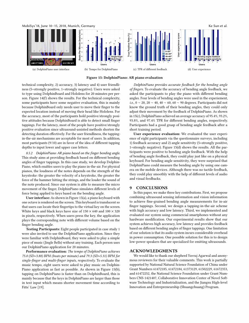
8.5.2 DolphinPiano: AR piano based on the finger bending angle.This study aims at providing feedback based on different bendingangles of finger tappings. In this case study, we develop Dolphin-Piano, which enables users to play the piano in-the-air. For physicalpianos, the loudness of the notes depends on the strength of thekeystroke: the greater the velocity of a keystroke, the greater theforce of the hammer hitting the strings, and the louder the sound ofthe note produced. Since our system is able to measure the micromovement of the finger, DolphinPiano simulates different levels offorce being applied to keys based on the bending angle.
User interface:As shown in Figure 15(a), a piano keyboard withone octave is rendered on the screen. This keyboard is translucent sothat users can locate their fingertips to the virtual key on the screen.White keys and black keys have size of 150 × 640 and 100 × 320in pixels, respectively. When users press the key, the applicationplays the corresponding note with different volume based on thefinger bending angle.
Testing Participants: Eight people participated in case study 1were also invited to use the DolphinPiano application. Since theywere familiar with DolphinBoard, they were asked to play a simplepiece of music (Jingle Bells) without any training. Each person usesour DolphinPiano application for 20 minutes.
Performance evaluation: The tempo of DolphinPiano achieves75.0 (SD=3.88) BPM (beats per minute) and 79.3 (SD=5.31) BPM forsingle-finger and multi-finger inputs, respectively. To evaluate themusic tempo, eight users were asked to play music on Dolphin-Piano application as fast as possible. As shown in Figure 15(b),tapping on DolphinPiano is faster than on DolphinBoard, this ismainly because that the keys in DolphinPiano are larger than thosein text input which means shorter movement time according toFitts’ Law [19].
DolphinPiano provides accurate feedback for the bending angleof fingers. To evaluate the accuracy of bending angle feedback, weasked the participants to play the piano with different bendingangles. Four levels of bending angles were used in the experiement,i.e., 0 ∼ 20, 20 ∼ 40, 40 ∼ 60, 60 ∼ 90 degrees. Participants did notknow the ground truth of their bending angles, they could onlyadjust their movement by the feedback of DolphinPiano. As shownin 15(c), DolphinPiano achieved an average accuracy of 95.4%, 93.2%,93.8%, and 97.4% TPR for different bending angles, respectively.Participants had a good grasp of bending angle feedback after ashort training period.
User experience evaluation: We evaluated the user experi-ence of eight participants via the questionnaire surveys, including1) feedback accuracy and 2) angle sensitivity (5=strongly positive,1=strongly negative). Figure 15(d) shows the results. All the par-ticipants were positive to bending angle feedback. With the helpof bending angle feedback, they could play just like on a physicalkeyboard. For bending angle sensitivity, they were surprised thatDolphinPiano could measure the bending angle by using one cam-era on the mobile devices. Although there was no tactile feedback,they could play smoothly with the help of different levels of audioand visual feedbacks.
9 CONCLUSIONSIn this paper, we make three key contributions. First, we propose
combining ultrasound sensing information and vision informationto achieve fine-grained bending angle measurements for in-airfinger tappings. Second, we design a tapping-in-the-air schemewith high accuracy and low latency. Third, we implemented andevaluated our system using commercial smartphones without anyhardware modification. Our experimental results show that oursystem achieves high accuracy, low latency and provides feedbackbased on different bending angles of finger tappings. One limitationof our solution is that its audio system incurs considerable overheadin power consumption. One possible solution for this is to designlow-power speakers that are specialized for emitting ultrasounds.
ACKNOWLEDGMENTSWewould like to thank our shepherd Yuvraj Agarwal and anony-
mous reviewers for their valuable comments. This work is partiallysupported by National Natural Science Foundation of China underGrant Numbers 61472185, 61472184, 61373129, 61502229, 61672353,and 61472252, the National Science Foundation under Grant Num-bers CNS-1421407, Collaborative Innovation Center of Novel Soft-ware Technology and Industrialization, and the Jiangsu High-levelInnovation and Entrepreneurship (Shuangchuang) Program.
Depth Aware Finger Tapping on Virtual Displays MobiSys’18, June 10–15, 2018, Munich, Germany
REFERENCES[1] Heba Abdelnasser, Moustafa Youssef, and Khaled A Harras. 2015. WiGest: A
ubiquitous WiFi-based gesture recognition system. In Proceedings of IEEE INFO-COM.
[2] C Albitar, P Graebling, and C Doignon. 2007. Robust Structured Light Coding for3D Reconstruction. In Proceedings of IEEE ICCV.
[3] Kamran Ali, Alex X. Liu, Wei Wang, and Muhammad Shahzad. 2015. KeystrokeRecognition Using WiFi Signals. In Proceedings of ACM MobiCom.
[4] Amazon. 2017. Alexa. https://developer.amazon.com/alexa. (2017).[5] Gunilla Borgefors. 1986. Distance transformations in digital images. Computer
Vision Graphics & Image Processing (1986).[6] Bo Chen, Vivek Yenamandra, and Kannan Srinivasan. 2015. Tracking Keystrokes
Using Wireless Signals. In Proceedings of ACM MobiSys.[7] Ke-Yu Chen, Daniel Ashbrook, Mayank Goel, Sung-Hyuck Lee, and Shwetak
Patel. 2014. AirLink: sharing files between multiple devices using in-air gestures.In Proceedings of ACM UbiComp.
[8] Xiang Anthony Chen, Julia Schwarz, Chris Harrison, Jennifer Mankoff, andScott E. Hudson. 2014. Air+touch:interweaving touch & in-air gestures. InProceedings of ACM UIST.
[9] Patricia Ivette Cornelio Martinez, Silvana De Pirro, Chi Thanh Vi, and SriramSubramanian. 2017. Agency in mid-air interfaces. In Proceedings of ACM CHI.
[10] Yan Cui, Sebastian Schuon, Derek Chan, Sebastian Thrun, and Christian Theobalt.2010. 3D shape scanning with a time-of-flight camera. In Proceedings of IEEECVPR.
[11] Google. 2016. Google Project Soli. https://www.google.com/atap/project-soli/.(2016).
[12] Claire C Gordon, Cynthia L Blackwell, Bruce Bradtmiller, Joseph L Parham,Jennifer Hotzman, Stephen P Paquette, Brian D Corner, and Belva M Hodge.1989. 2010 Anthropometric Survey of U.S. Marine Corps Personnel: Methods andSummary Statistics. Anthropometric Survey of U.s.army Personnel Methods andSummary Statistics (1989).
[13] Sidhant Gupta, Daniel Morris, Shwetak Patel, and Desney Tan. 2012. Soundwave:using the doppler effect to sense gestures. In Proceedings of ACM CHI.
[14] Masakazu Higuchi and Takashi Komuro. 2015. Multi-finger AR Typing Interfacefor Mobile Devices Using High-Speed Hand Motion Recognition. In Proceedingsof ACM CHI.
[15] Intel. 2017. Intel Realsense. http://www.intel.com/content/www/us/en/architecture-and-technology/realsense-overview.html. (2017).
[16] Bryce Kellogg, Vamsi Talla, and Shyamnath Gollakota. 2014. Bringing gesturerecognition to all devices. In Proceedings of Usenix NSDI.
[17] Kourosh Khoshelham. 2011. Accuracy analysis of kinect depth data. In ISPRSworkshop Laser Scanning.
[18] Jian Liu, Yan Wang, Gorkem Kar, Yingying Chen, Jie Yang, and Marco Gruteser.2015. Snooping Keystrokes with mm-level Audio Ranging on a Single Phone. InProceedings of ACM MobiCom.
[19] I. Scott Mackenzie. 1992. Fitts’ Law as a Research and Design Tool in Human-Computer Interaction. Human-Computer Interaction (1992).
[20] PedroMelgarejo, Xinyu Zhang, Parameswaran Ramanathan, and David Chu. 2014.Leveraging directional antenna capabilities for fine-grained gesture recognition.In Proceedings of ACM UbiComp.
[21] Microsoft. 2014. Microsoft Kinect. http://www.microsoft.com/en-us/kinectforwindows/. (2014).
[22] Microsoft. 2016. Microsoft Hololens. http://www.microsoft.com/microsoft-hololens/en-us. (2016).
[23] Robert B Miller. 1968. Response time in man-computer conversational transac-tions. In Proceedings of ACM AFIPS.
[24] Mark R Mine, Frederick P Brooks Jr, and Carlo H Sequin. 1997. Moving ob-jects in space: exploiting proprioception in virtual-environment interaction. InProceedings of ACM SIGGRAPH.
[25] Leap Motion. 2015. Leap Motion. https://www.leapmotion.com/. (2015).[26] Taichi Murase, Atsunori Moteki, Noriaki Ozawa, Nobuyuki Hara, Takehiro Nakai,
and Katsuhito Fujimoto. 2011. Gesture keyboard requiring only one camera. InProceedings of ACM UIST.
[27] Rajalakshmi Nandakumar, Vikram Iyer, Desney Tan, and Shyamnath Gollakota.2016. FingerIO: Using Active Sonar for Fine-Grained Finger Tracking. In Proceed-ings of ACM CHI.
[28] OptiTrack. 2018. OptiTrack. http://www.optitrack.com. (2018).[29] Nobuyuki Otsu. 1975. A threshold selection method from gray-level histograms.
Automatica (1975).[30] S. L. Phung, A. Bouzerdoum, and D. Chai. 2005. Skin segmentation using color
pixel classification: analysis and comparison. IEEE Transactions on Pattern Analy-sis & Machine Intelligence (2005).
[31] Qifan Pu, Sidhant Gupta, Shyamnath Gollakota, and Shwetak Patel. 2013. Whole-home gesture recognition usingwireless signals. In Proceedings of ACMMobiCom.
[32] Rajesh PN Rao. 2013. Brain-computer interfacing: an introduction. CambridgeUniversity Press.
[33] Anthony Santella, Maneesh Agrawala, Doug DeCarlo, David Salesin, and MichaelCohen. 2006. Gaze-based interaction for semi-automatic photo cropping. InProceedings of ACM CHI.
[34] Hamed Sarbolandi, Damien Lefloch, and Andreas Kolb. 2015. Kinect rangesensing: Structured-light versus Time-of-Flight Kinect âŸĘ. Computer Vision andImage Understanding (2015).
[35] Jie Song, Gábor Sörös, Fabrizio Pece, Sean Ryan Fanello, Shahram Izadi, CemKeskin, and Otmar Hilliges. 2014. In-air gestures around unmodified mobiledevices. In Proceedings of ACM UIST.
[36] Jue Wang, Deepak Vasisht, and Dina Katabi. 2014. RF-IDraw: virtual touch screenin the air using RF signals. In Proceedings of ACM SIGCOMM.
[37] Junjue Wang, Kaichen Zhao, Xinyu Zhang, and Chunyi Peng. 2014. Ubiquitouskeyboard for small mobile devices: harnessing multipath fading for fine-grainedkeystroke localization. In Proceedings of ACM MobiSys.
[38] Wei Wang, Alex X. Liu, and Ke Sun. 2016. Device-free gesture tracking usingacoustic signals. In Proceedings of ACM MobiCom.
[39] Yan Wang, Jian Liu, Yingying Chen, Marco Gruteser, Jie Yang, and Hongbo Liu.2014. E-eyes: In-home Device-free Activity Identification Using Fine-grainedWiFi Signatures. In Proceedings of ACM MobiCom.
[40] Teng Wei and Xinyu Zhang. 2015. mTrack: High-Precision Passive TrackingUsing Millimeter Wave Radios. In Proceedings of ACM MobiCom.
[41] FrankWeichert, Daniel Bachmann, Bartholomäus Rudak, and Denis Fisseler. 2013.Analysis of the accuracy and robustness of the leap motion controller. Sensors(2013).
[42] Xin Yi, Chun Yu, Mingrui Zhang, Sida Gao, Ke Sun, and Yuanchun Shi. 2015.ATK: Enabling Ten-Finger Freehand Typing in Air Based on 3D Hand TrackingData. In Proceedings of ACM UIST.
[43] Yafeng Yin, Qun Li, Lei Xie, Shanhe Yi, Ed Novak, and Sanglu Lu. 2016. CamK: aCamera-based Keyboard for Small Mobile Devices. In Proceedings of IEEE INFO-COM.
[44] Sangki Yun, Yi-Chao Chen, Huihuang Zheng, Lili Qiu, and Wenguang Mao. 2017.Strata: Fine-Grained Acoustic-based Device-Free Tracking. In Proceedings of ACMMobisys.
[45] Chi Zhang, Josh Tabor, Jialiang Zhang, and Xinyu Zhang. 2015. Extending MobileInteraction Through Near-Field Visible Light Sensing. In Proceedings of ACMMobiCom.
[46] Guoming Zhang, Chen Yan, Xiaoyu Ji, Tianchen Zhang, Taimin Zhang, andWenyuan Xu. 2017. DolphinAttack: Inaudible voice commands. In Proceedings ofACM CCS.
[47] Lide Zhang, Birjodh Tiwana, Zhiyun Qian, Zhaoguang Wang, Robert P. Dick,Zhuoqing Morley Mao, and Lei Yang. 2010. Accurate online power estimationand automatic battery behavior based power model generation for smartphones.In Proceedings of IEEE CODES+ISSS.
[48] Chenyin Zhao and Songqing Fan. 2002. Measurement of Fingers. Progress ofAnatomical Sciences (2002).