Embed Size (px)
Citation preview
Deployment of Dell M8024-k Blade Switch with Cisco Nexus 5000 Series Switch
A Dell Interoperability Whitepaper
Victor Teeter
Deployment of Dell M8024-k Blade Switch with Cisco Nexus 5000 Series Switch
Page ii
THIS TECHNICAL INTEROPERABILITY WHITE PAPER IS FOR INFORMATIONAL PURPOSES ONLY, AND
MAY CONTAIN TYPOGRAPHICAL ERRORS AND TECHNICAL INACCURACIES. THE CONTENT IS
PROVIDED AS IS, WITHOUT EXPRESS OR IMPLIED WARRANTIES OF ANY KIND.
© 2011 Dell Inc. All rights reserved. Reproduction or translation of any part of this work beyond that
permitted by U.S. copyright laws without the written permission of Dell Inc. is unlawful and strictly
forbidden. For more information, contact Dell.
Dell, the DELL logo, the DELL badge, PowerConnect and PowerEdge are trademarks of Dell Inc.. Other
trademarks and trade names may be used in this document to refer to either the entities claiming the
marks and names or their products. Dell Inc. disclaims any proprietary interest in trademarks and trade
names other than its own.
October 2011
Deployment of Dell M8024-k Blade Switch with Cisco Nexus 5000 Series Switch
Page 1
Contents
Contents .................................................................................................................... 1
Summary .................................................................................................................... 3
Simple Switch Mode ....................................................................................................... 3
Testing Scenarios .......................................................................................................... 4
Scenario 1: Enabling Spanning Tree (RSTP) and Creating a LAG (Link Aggregation) on the Dell
PowerConnect M8024-k Switch ....................................................................................... 5
Configuring the Dell M8024-k Switch ............................................................................. 5
Configuring the Cisco 5020 Switch ................................................................................ 7
Validation ............................................................................................................. 7
Scenario 2: Configuring an Untagged VLAN on a Single LAG .................................................... 8
Configuring the Dell M8024-k Switch ............................................................................. 8
Configuring the Cisco 5020 Switch .............................................................................. 12
Validation ........................................................................................................... 13
Scenario 3: Configuring Multiple VLANs on a Single LAG ...................................................... 15
Configuring the Dell M8024-k Switch ........................................................................... 16
Configuring the Cisco 5020 Switch .............................................................................. 25
Validation ........................................................................................................... 26
Scenario 4: Configuring Multiple LAGs and Dedicating Specific Uplinks Using VLANs .................... 27
Configuring the Dell M8024-k Switch ........................................................................... 27
Configuring the Cisco 5020 Switch .............................................................................. 37
Validation ........................................................................................................... 38
Scenario 5: Configuring Multiple VLANs on Multiple LAGs ..................................................... 39
Configuring the Dell M8024-k Switch ........................................................................... 39
Configuring the Cisco Nexus 5020 Switch ...................................................................... 53
Validation ........................................................................................................... 55
Scenario 6: Configuring a Backup LAG for Failover ............................................................. 56
Configuring the Dell M8024-k Switch ........................................................................... 56
Configuring the Cisco Nexus 5020 Switch ...................................................................... 63
Validation ........................................................................................................... 63
Appendix - Network Switch Versions ................................................................................. 64
About Dell................................................................................................................. 64
Deployment of Dell M8024-k Blade Switch with Cisco Nexus 5000 Series Switch
Page 2
Figures
Figure 1. The Dell PowerConnect M8024-k Switch ............................................................... 3
Figure 2. Graphic Representation of Scenario 1 .................................................................. 5
Figure 3. Graphic Representation of Scenario 2. ................................................................. 8
Figure 4. Graphic Representation of Scenario 3. ............................................................... 15
Figure 5. Graphic Representation of Scenario 4. ............................................................... 27
Figure 6. Graphic Representation of Scenario 5. ............................................................... 39
Figure 7. Graphic representation of Scenario 6. ............................................................... 56
Tables
Table 1. Switch Firmware Versions .............................................................................. 64

Deployment of Dell M8024-k Blade Switch with Cisco Nexus 5000 Series Switch
Page 3
Summary
Adding a Dell™ PowerConnect™ blade (M-Series) switch, with a Dell PowerEdge™ M1000e modular
blade enclosure to an external Cisco Nexus Switch is a straightforward process. This document is
targeted at today’s FC SAN and Ethernet LAN environments and meant to serve as a supplementary
guide on how to interconnect equipment that makes up datacenter.
This document provides an easy to use step-by-step guide on how to configure and deploy DELL M-
Series 10Gbit/s Blade Switch (M8024-k) (see Figure 1) with a Cisco Nexus 5000 Series Switch. For the
examples in this guide, the Nexus 5020 was used.
12
34
CO
NS
OL
E
PowerConnect M8024-k
17
18
19
20
Figure 1. The Dell PowerConnect M8024-k Switch
Simple Switch Mode
Simple Switch Mode, or SSM, allows server administrators, or anyone with very limited expertise in
configuring Ethernet Switches, the ability to deploy a loop-free switching solution without having to
configure the Spanning Tree Protocol (STP) or design its integration into the existing environment.
The primary advantages of deploying SSM are as follows:
Port Aggregation is easy to configure. Simply group internal ports and associate with external
ports, assign VLANs (if required), and it’s ready to go.
SSM automatically configures multiple external ports into a Link Aggregation Control Protocol
(LACP) trunk group.
By using Aggregator Groups, the Simple Switch Mode provides loop-free operation without
using STP.
Port Aggregation is completely interoperable. Dynamic (via LACP) and static link aggregation
is supported on the external ports.
This document does not use SSM, but instead guides the user through the steps using the Normal
mode of operation. To learn more about SSM or find the associated SSM configurations as shown in
the guide, download the white paper titled “Deployment of Dell M8024-k Blade Switch in Simple
Mode with Cisco Nexus 5000-series Switch”.
Deployment of Dell M8024-k Blade Switch with Cisco Nexus 5000 Series Switch
Page 4
Testing Scenarios
The following sections will present an overview of a variety of different network deployment
scenarios and will provide step-by-step set up guidance using configuration tools, with screen shots
as a visual guide.
Each of the following scenarios in this document assumes that the PowerConnect device is in
Normal Mode configuration. If Simple Mode is enabled it will need to be disabled.
All scenarios assume that the M8024-k is using external ports 17-20 and that no module is
installed providing additional external ports.
Be sure to enable the Spanning Tree protocol on both network devices for proper functioning
before setting up any of the configurations mentioned in this documentation. Scenario 1
provides steps on how to do this.
Deployment of Dell M8024-k Blade Switch with Cisco Nexus 5000 Series Switch
Page 5
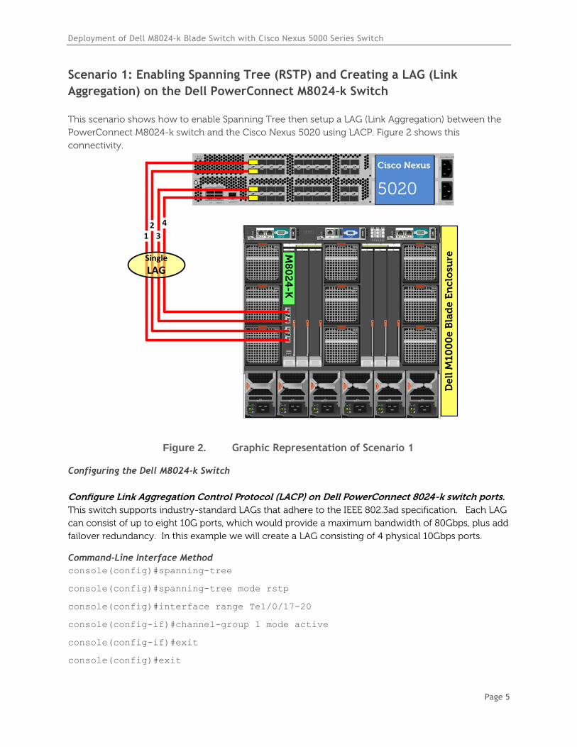
Scenario 1: Enabling Spanning Tree (RSTP) and Creating a LAG (Link
Aggregation) on the Dell PowerConnect M8024-k Switch
This scenario shows how to enable Spanning Tree then setup a LAG (Link Aggregation) between the
PowerConnect M8024-k switch and the Cisco Nexus 5020 using LACP. Figure 2 shows this
connectivity.
`STAT
CONSOLE
L1
L2
MGMT 0
MGMT 14 8 12 16
3 7 11 15
2 6 10 14
1 5 9 13
20 24 28 32
19 23 27 31
18 22 26 30
17 21 25 29
SLO
T2
34 38
33 37
36 40
35 39
SLO
T3
Cisco Nexus 5020
PS
1P
S2
200-240v-6A50~60Hz
De
ll M
10
00
e B
lad
e E
nc
losu
re
B2C2 A2B1 C1A1
4
1
7
5
2
8
6
3
9
CMC2CMC1 KVM
1 2 3 4 5 6
GbGb 21
CMC
iKVM
GbGb 21
CMC
12
34
CONSOLE
Po
we
rC
on
ne
ct M
80
24
-k
17
18
19
20
M8
02
4-K
12
3
4
Cisco Nexus
5020
Single
LAG
Figure 2. Graphic Representation of Scenario 1
Configuring the Dell M8024-k Switch
Configure Link Aggregation Control Protocol (LACP) on Dell PowerConnect 8024-k switch ports.
This switch supports industry-standard LAGs that adhere to the IEEE 802.3ad specification. Each LAG
can consist of up to eight 10G ports, which would provide a maximum bandwidth of 80Gbps, plus add
failover redundancy. In this example we will create a LAG consisting of 4 physical 10Gbps ports.
Command-Line Interface Method
console(config)#spanning-tree
console(config)#spanning-tree mode rstp
console(config)#interface range Te1/0/17-20
console(config-if)#channel-group 1 mode active
console(config-if)#exit
console(config)#exit
Deployment of Dell M8024-k Blade Switch with Cisco Nexus 5000 Series Switch
Page 6
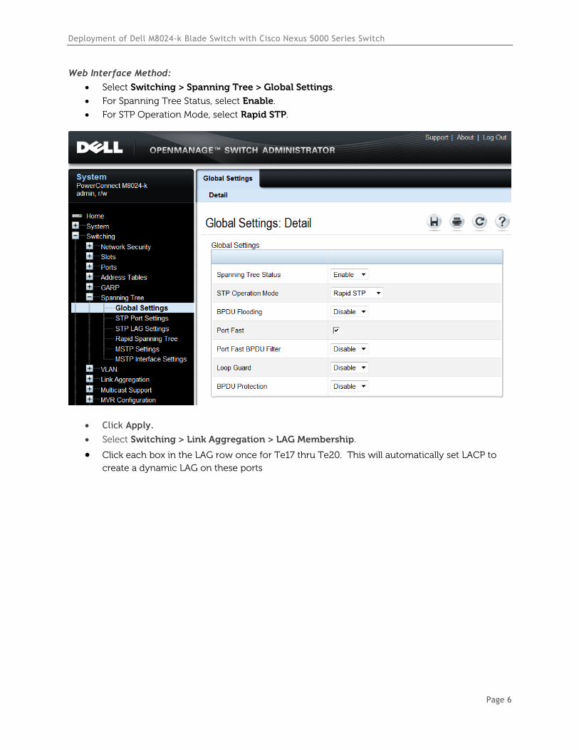
Web Interface Method:
Select Switching > Spanning Tree > Global Settings.
For Spanning Tree Status, select Enable.
For STP Operation Mode, select Rapid STP.
Click Apply.
Select Switching > Link Aggregation > LAG Membership.
Click each box in the LAG row once for Te17 thru Te20. This will automatically set LACP to
create a dynamic LAG on these ports
Deployment of Dell M8024-k Blade Switch with Cisco Nexus 5000 Series Switch
Page 7
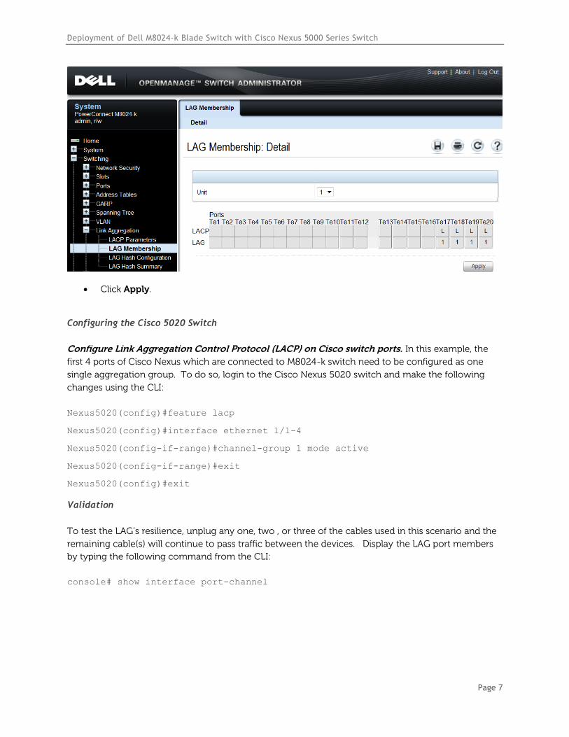
Click Apply.
Configuring the Cisco 5020 Switch
Configure Link Aggregation Control Protocol (LACP) on Cisco switch ports. In this example, the
first 4 ports of Cisco Nexus which are connected to M8024-k switch need to be configured as one
single aggregation group. To do so, login to the Cisco Nexus 5020 switch and make the following
changes using the CLI:
Nexus5020#config
Nexus5020(config)#feature lacp
Nexus5020(config)#interface ethernet 1/1-4
Nexus5020(config-if-range)#channel-group 1 mode active
Nexus5020(config-if-range)#exit
Nexus5020(config)#exit
Validation
To test the LAG’s resilience, unplug any one, two , or three of the cables used in this scenario and the
remaining cable(s) will continue to pass traffic between the devices. Display the LAG port members
by typing the following command from the CLI:
console# show interface port-channel
Deployment of Dell M8024-k Blade Switch with Cisco Nexus 5000 Series Switch
Page 8
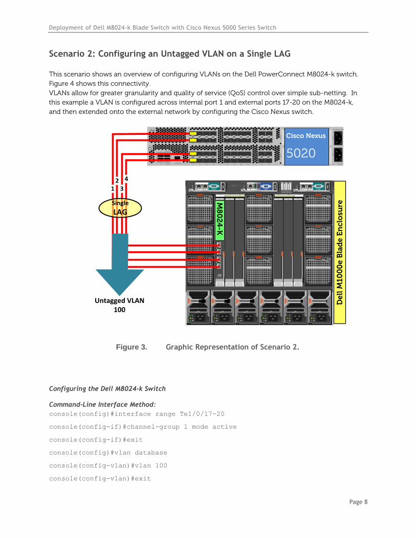
Scenario 2: Configuring an Untagged VLAN on a Single LAG
This scenario shows an overview of configuring VLANs on the Dell PowerConnect M8024-k switch.
Figure 4 shows this connectivity.
VLANs allow for greater granularity and quality of service (QoS) control over simple sub-netting. In
this example a VLAN is configured across internal port 1 and external ports 17-20 on the M8024-k,
and then extended onto the external network by configuring the Cisco Nexus switch.
`STAT
CONSOLE
L1
L2
MGMT 0
MGMT 14 8 12 16
3 7 11 15
2 6 10 14
1 5 9 13
20 24 28 32
19 23 27 31
18 22 26 30
17 21 25 29
SLO
T2
34 38
33 37
36 40
35 39
SLO
T3
Cisco Nexus 5020
PS
1P
S2
200-240v-6A50~60Hz
De
ll M
10
00
e B
lad
e E
nc
losu
re
B2C2 A2B1 C1A1
4
1
7
5
2
8
6
3
9
CMC2CMC1 KVM
1 2 3 4 5 6
GbGb 21
CMC
iKVM
GbGb 21
CMC
12
34
CONSOLE
Po
we
rC
on
ne
ct M
80
24
-k
17
18
19
20
M8
02
4-K
12
3
4
Cisco Nexus
5020
Single
LAG
Untagged VLAN 100
Figure 3. Graphic Representation of Scenario 2.
Configuring the Dell M8024-k Switch
Command-Line Interface Method:
console(config)#interface range Te1/0/17-20
console(config-if)#channel-group 1 mode active
console(config-if)#exit
console(config)#vlan database
console(config-vlan)#vlan 100
console(config-vlan)#exit
Deployment of Dell M8024-k Blade Switch with Cisco Nexus 5000 Series Switch
Page 9
console(config)#interface port-channel 1
console(config-if-Po1)#switchport mode general
console(config-if-Po1)#switchport general allowed vlan add 100 untagged
console(config-if-Po1)#switchport general pvid 100
console(config-if-Po1)#exit
console(config)#interface vlan 100
console(config-if-vlan100)#ip address 1.1.1.10 255.255.255.0
console(config-if-vlan100)#exit
console(config)#interface Te1/0/1
console(config-if-Te1/0/1)#switchport access VLAN 100
console(config-if-Te1/0/1)#exit
console(config)#exit
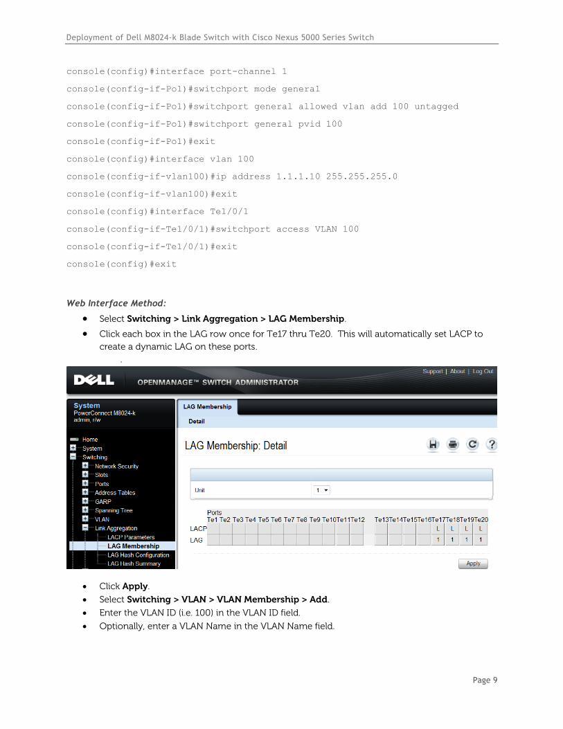
Web Interface Method:
Select Switching > Link Aggregation > LAG Membership.
Click each box in the LAG row once for Te17 thru Te20. This will automatically set LACP to
create a dynamic LAG on these ports. .
Click Apply.
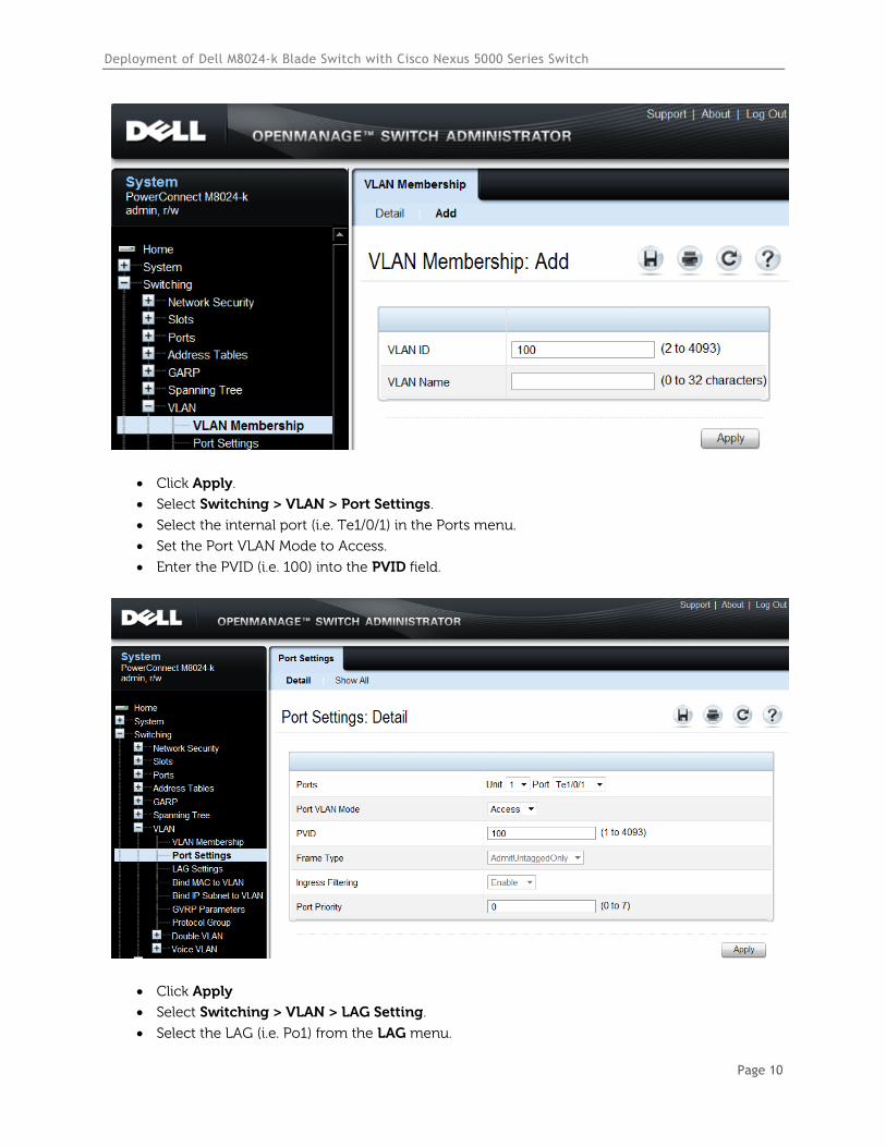
Select Switching > VLAN > VLAN Membership > Add.
Enter the VLAN ID (i.e. 100) in the VLAN ID field.
Optionally, enter a VLAN Name in the VLAN Name field.
Deployment of Dell M8024-k Blade Switch with Cisco Nexus 5000 Series Switch
Page 10
Click Apply.
Select Switching > VLAN > Port Settings.
Select the internal port (i.e. Te1/0/1) in the Ports menu.
Set the Port VLAN Mode to Access.
Enter the PVID (i.e. 100) into the PVID field.
Click Apply
Select Switching > VLAN > LAG Setting.
Select the LAG (i.e. Po1) from the LAG menu.
Deployment of Dell M8024-k Blade Switch with Cisco Nexus 5000 Series Switch
Page 11
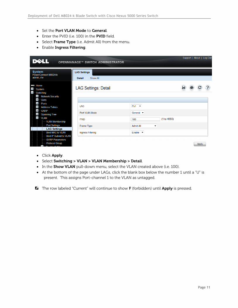
Set the Port VLAN Mode to General.
Enter the PVID (i.e. 100) in the PVID field.
Select Frame Type (i.e. Admit All) from the menu.
Enable Ingress Filtering.
Click Apply.
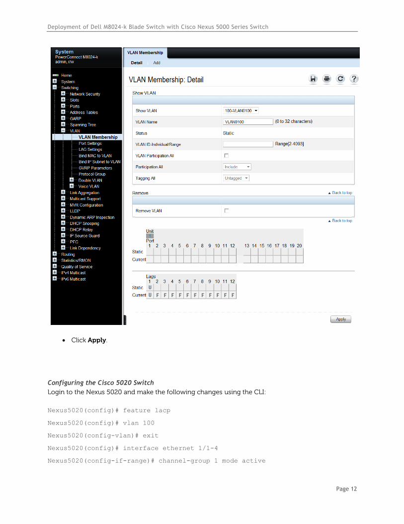
Select Switching > VLAN > VLAN Membership > Detail.
In the Show VLAN pull-down menu, select the VLAN created above (i.e. 100).
At the bottom of the page under LAGs, click the blank box below the number 1 until a “U” is
present. This assigns Port-channel 1 to the VLAN as untagged.
The row labeled “Current” will continue to show F (forbidden) until Apply is pressed.
Deployment of Dell M8024-k Blade Switch with Cisco Nexus 5000 Series Switch
Page 12
Click Apply.
Configuring the Cisco 5020 Switch
Login to the Nexus 5020 and make the following changes using the CLI:xus5020# configure
Enter configuration commands, one per line. End with CNTL/Z.
Nexus5020(config)# feature lacp
Nexus5020(config)# vlan 100
Nexus5020(config-vlan)# exit
Nexus5020(config)# interface ethernet 1/1-4
Nexus5020(config-if-range)# channel-group 1 mode active
Deployment of Dell M8024-k Blade Switch with Cisco Nexus 5000 Series Switch
Page 13
Nexus5020(config-if-range)# exit
Nexus5020(config)# interface port-channel 1
Nexus5020(config-if)# switchport mode trunk
Nexus5020(config-if)# switchport trunk native vlan 100
Nexus5020(config-if)# end
Validation
The next steps are optional, but can be used to validate or troubleshoot the VLAN and LAG setup.
Command-Line Interface Method:
console(config)#interface vlan 100
console(config-if-vlan100)#ip address 1.1.1.10 255.255.255.0
console(config-if-vlan100)#exit
console(config)#exit
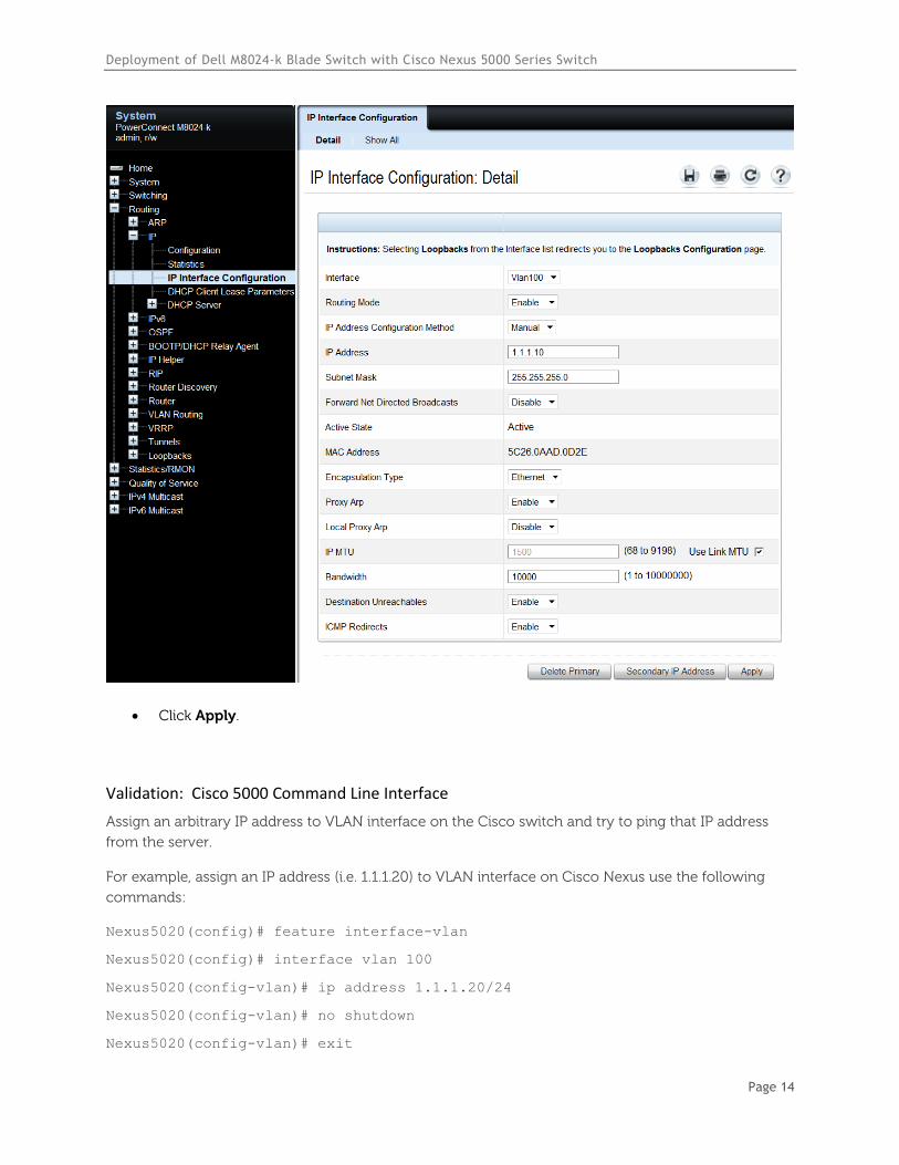
Web Interface Method:
Select Routing > IP > IP Interface Configuration.
Select the VLAN (i.e. Vlan100) from the Interface menu.
Enable Routing Mode.
Change the IP Address Configuration Method to Manual.
Provide an IP Address and Subnet Mask in the appropriate fields. (i.e. 1.1.1.10 and
255.255.255.0).
Deployment of Dell M8024-k Blade Switch with Cisco Nexus 5000 Series Switch
Page 14
Click Apply.
Validation: Cisco 5000 Command Line Interface
Assign an arbitrary IP address to VLAN interface on the Cisco switch and try to ping that IP address
from the server.
For example, assign an IP address (i.e. 1.1.1.20) to VLAN interface on Cisco Nexus use the following
commands:
Nexus5020(config)# feature interface-vlan
Nexus5020(config)# interface vlan 100
Nexus5020(config-vlan)# ip address 1.1.1.20/24
Nexus5020(config-vlan)# no shutdown
Nexus5020(config-vlan)# exit
Deployment of Dell M8024-k Blade Switch with Cisco Nexus 5000 Series Switch
Page 15
Next, add an IP address (i.e. 1.1.1.5) to the Server blade in the M1000e blade enclosure. A ping should
be successful between the Cisco Nexus and the M1000e server, between the Cisco Nexus and the
M8024-k, and between the M8024-k and the Server blade.
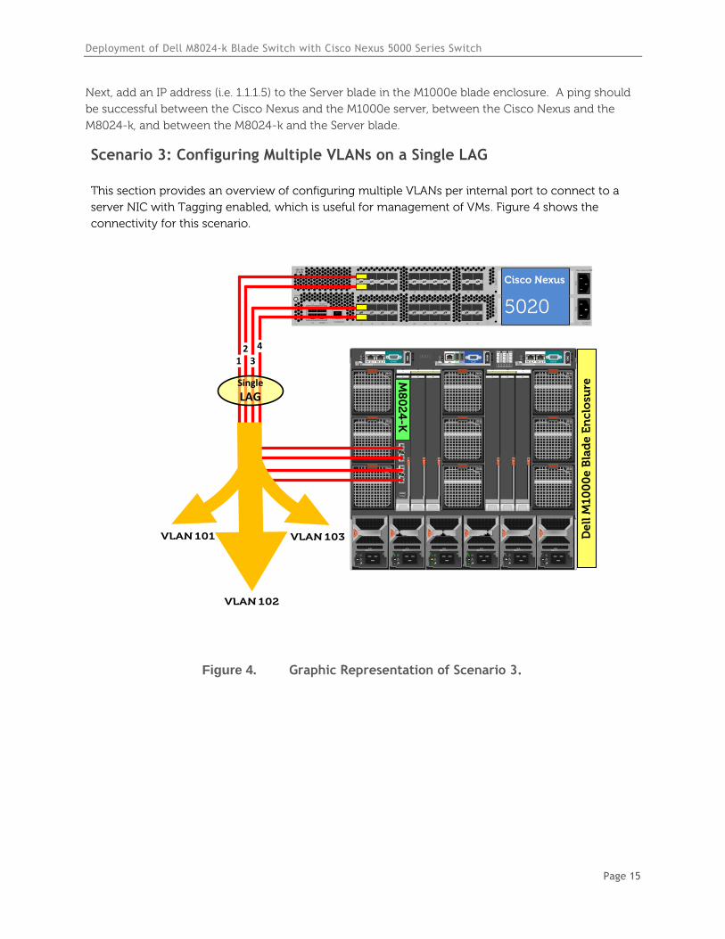
Scenario 3: Configuring Multiple VLANs on a Single LAG
This section provides an overview of configuring multiple VLANs per internal port to connect to a
server NIC with Tagging enabled, which is useful for management of VMs. Figure 4 shows the
connectivity for this scenario.
`STAT
CONSOLE
L1
L2
MGMT 0
MGMT 14 8 12 16
3 7 11 15
2 6 10 14
1 5 9 13
20 24 28 32
19 23 27 31
18 22 26 30
17 21 25 29
SLO
T2
34 38
33 37
36 40
35 39
SLO
T3
Cisco Nexus 5020
PS
1P
S2
200-240v-6A50~60Hz
De
ll M
10
00
e B
lad
e E
nc
losu
re
B2C2 A2B1 C1A1
4
1
7
5
2
8
6
3
9
CMC2CMC1 KVM
1 2 3 4 5 6
GbGb 21
CMC
iKVM
GbGb 21
CMC
12
34
CONSOLE
Po
we
rC
on
ne
ct M
80
24
-k
17
18
19
20
M8
02
4-K
12
3
4
Cisco Nexus
5020
Single
LAG
VLAN 102
VLAN 103VLAN 101
Figure 4. Graphic Representation of Scenario 3.
Deployment of Dell M8024-k Blade Switch with Cisco Nexus 5000 Series Switch
Page 16
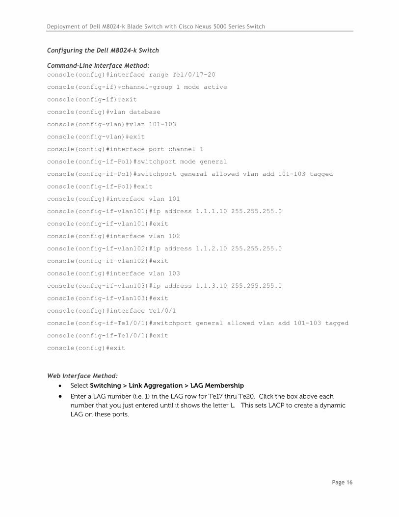
Configuring the Dell M8024-k Switch
Command-Line Interface Method:
console(config)#interface range Te1/0/17-20
console(config-if)#channel-group 1 mode active
console(config-if)#exit
console(config)#vlan database
console(config-vlan)#vlan 101-103
console(config-vlan)#exit
console(config)#interface port-channel 1
console(config-if-Po1)#switchport mode general
console(config-if-Po1)#switchport general allowed vlan add 101-103 tagged
console(config-if-Po1)#exit
console(config)#interface vlan 101
console(config-if-vlan101)#ip address 1.1.1.10 255.255.255.0
console(config-if-vlan101)#exit
console(config)#interface vlan 102
console(config-if-vlan102)#ip address 1.1.2.10 255.255.255.0
console(config-if-vlan102)#exit
console(config)#interface vlan 103
console(config-if-vlan103)#ip address 1.1.3.10 255.255.255.0
console(config-if-vlan103)#exit
console(config)#interface Te1/0/1
console(config-if-Te1/0/1)#switchport general allowed vlan add 101-103 tagged
console(config-if-Te1/0/1)#exit
console(config)#exit
Web Interface Method:
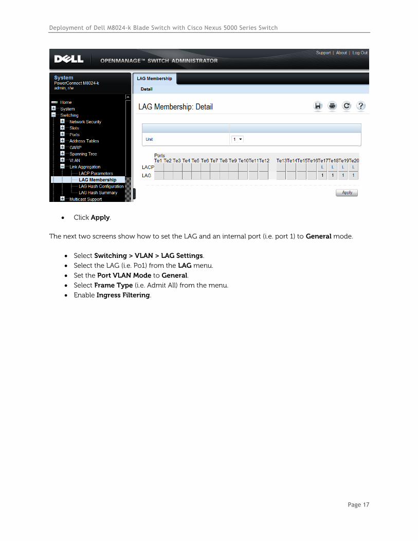
Select Switching > Link Aggregation > LAG Membership
Enter a LAG number (i.e. 1) in the LAG row for Te17 thru Te20. Click the box above each
number that you just entered until it shows the letter L. This sets LACP to create a dynamic
LAG on these ports.
Deployment of Dell M8024-k Blade Switch with Cisco Nexus 5000 Series Switch
Page 17
Click Apply.
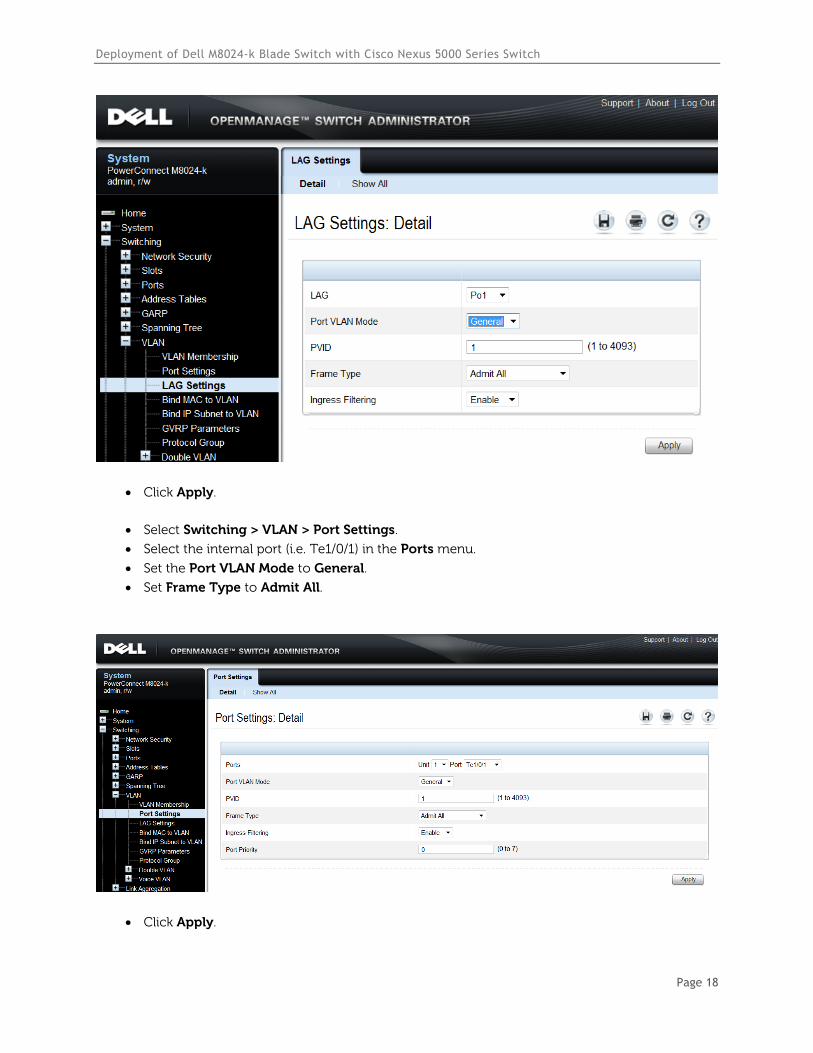
The next two screens show how to set the LAG and an internal port (i.e. port 1) to General mode.
Select Switching > VLAN > LAG Settings.
Select the LAG (i.e. Po1) from the LAG menu.
Set the Port VLAN Mode to General.
Select Frame Type (i.e. Admit All) from the menu.
Enable Ingress Filtering.
Deployment of Dell M8024-k Blade Switch with Cisco Nexus 5000 Series Switch
Page 18
Click Apply.
Select Switching > VLAN > Port Settings.
Select the internal port (i.e. Te1/0/1) in the Ports menu.
Set the Port VLAN Mode to General.
Set Frame Type to Admit All.
Click Apply.
Deployment of Dell M8024-k Blade Switch with Cisco Nexus 5000 Series Switch
Page 19
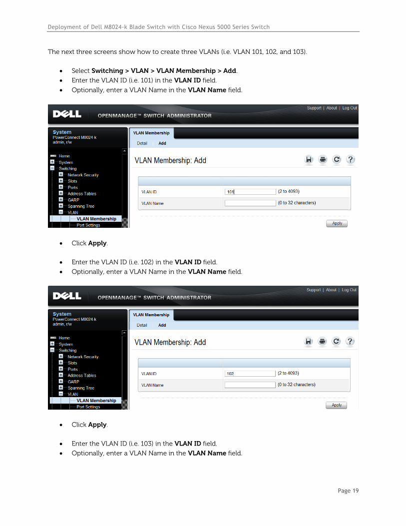
The next three screens show how to create three VLANs (i.e. VLAN 101, 102, and 103).
Select Switching > VLAN > VLAN Membership > Add.
Enter the VLAN ID (i.e. 101) in the VLAN ID field.
Optionally, enter a VLAN Name in the VLAN Name field.
Click Apply.
Enter the VLAN ID (i.e. 102) in the VLAN ID field.
Optionally, enter a VLAN Name in the VLAN Name field.
Click Apply.
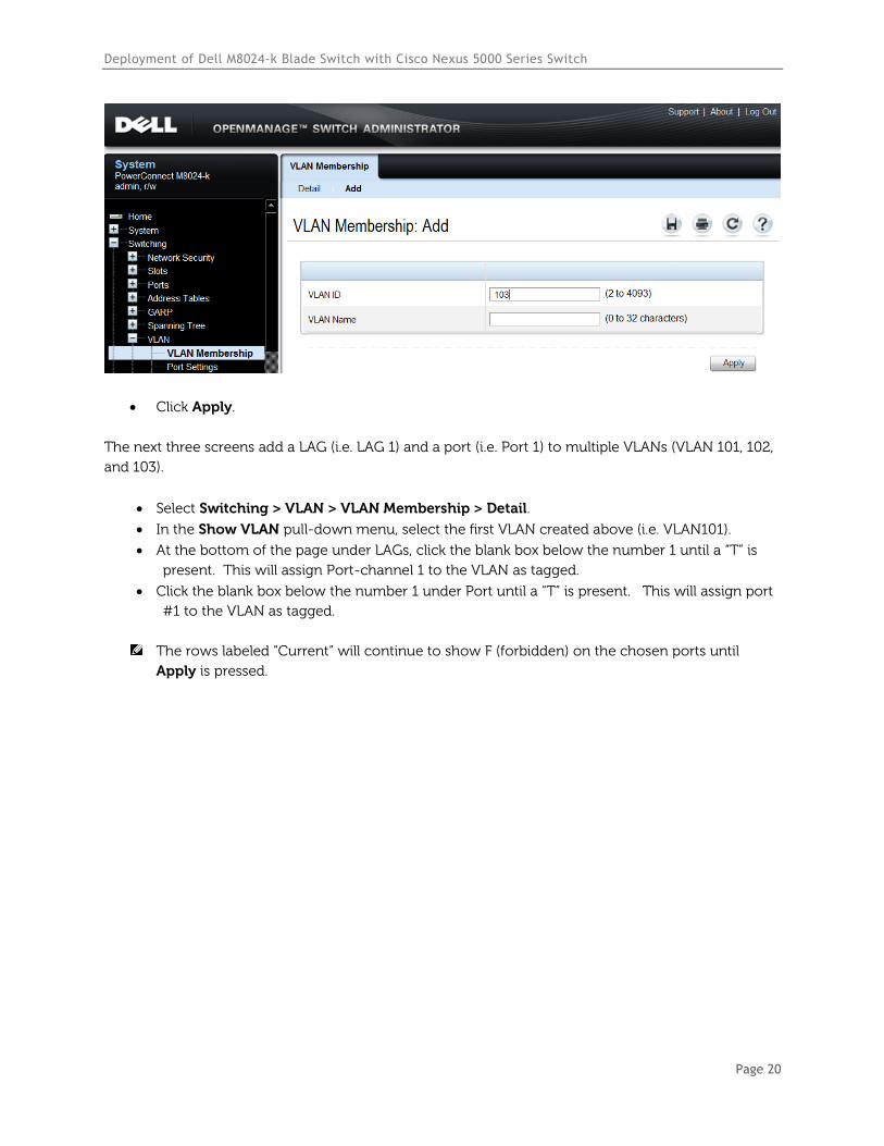
Enter the VLAN ID (i.e. 103) in the VLAN ID field.
Optionally, enter a VLAN Name in the VLAN Name field.
Deployment of Dell M8024-k Blade Switch with Cisco Nexus 5000 Series Switch
Page 20
Click Apply.
The next three screens add a LAG (i.e. LAG 1) and a port (i.e. Port 1) to multiple VLANs (VLAN 101, 102,
and 103).
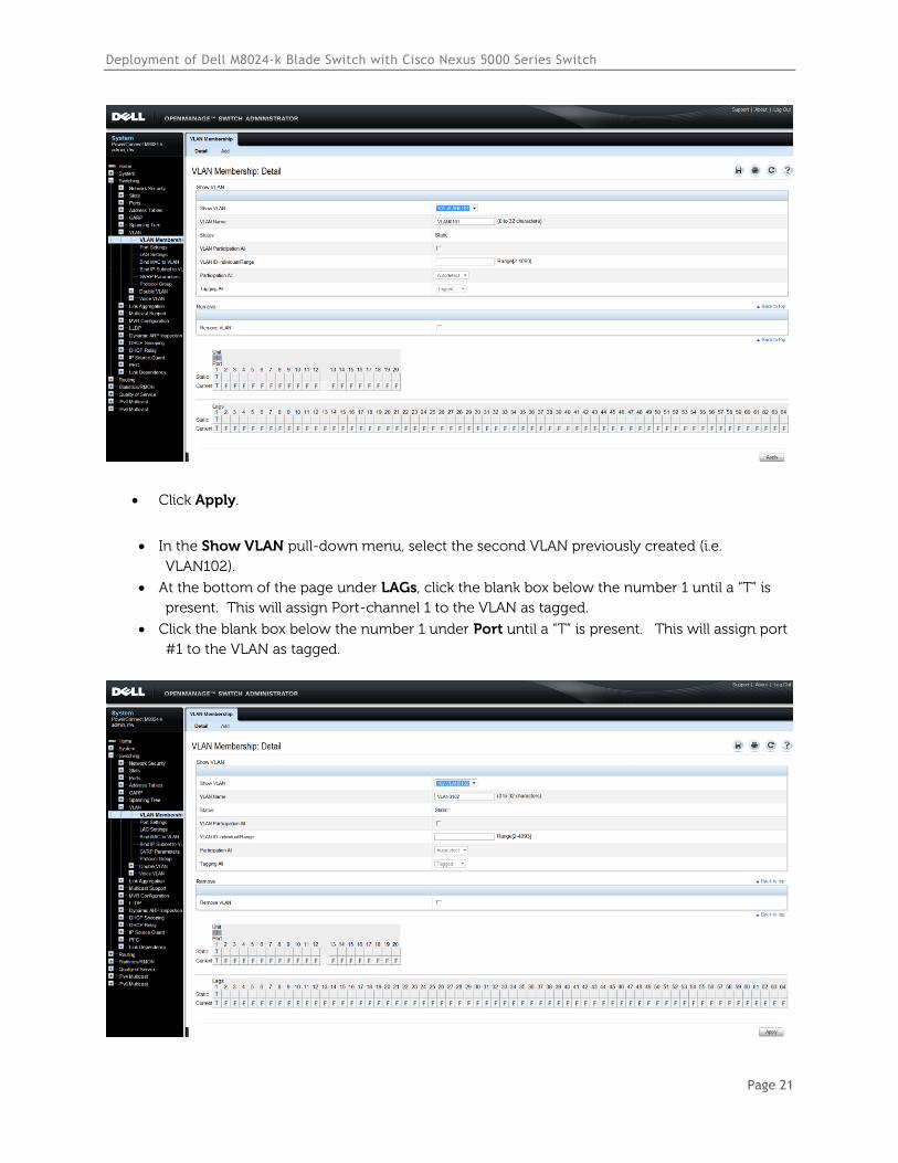
Select Switching > VLAN > VLAN Membership > Detail.
In the Show VLAN pull-down menu, select the first VLAN created above (i.e. VLAN101).
At the bottom of the page under LAGs, click the blank box below the number 1 until a “T” is
present. This will assign Port-channel 1 to the VLAN as tagged.
Click the blank box below the number 1 under Port until a “T” is present. This will assign port
#1 to the VLAN as tagged.
The rows labeled “Current” will continue to show F (forbidden) on the chosen ports until
Apply is pressed.
Deployment of Dell M8024-k Blade Switch with Cisco Nexus 5000 Series Switch
Page 21
Click Apply.
In the Show VLAN pull-down menu, select the second VLAN previously created (i.e.
VLAN102).
At the bottom of the page under LAGs, click the blank box below the number 1 until a “T” is
present. This will assign Port-channel 1 to the VLAN as tagged.
Click the blank box below the number 1 under Port until a “T” is present. This will assign port
#1 to the VLAN as tagged.
Deployment of Dell M8024-k Blade Switch with Cisco Nexus 5000 Series Switch
Page 22
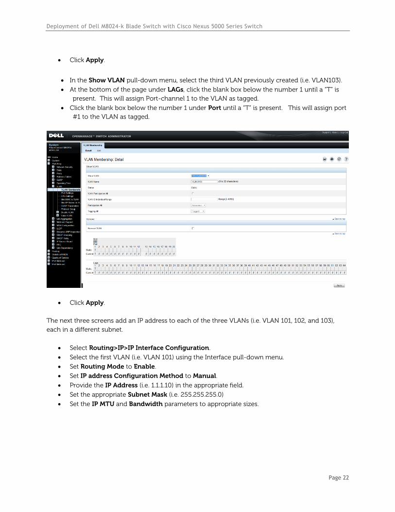
Click Apply.
In the Show VLAN pull-down menu, select the third VLAN previously created (i.e. VLAN103).
At the bottom of the page under LAGs, click the blank box below the number 1 until a “T” is
present. This will assign Port-channel 1 to the VLAN as tagged.
Click the blank box below the number 1 under Port until a “T” is present. This will assign port
#1 to the VLAN as tagged.
Click Apply.
The next three screens add an IP address to each of the three VLANs (i.e. VLAN 101, 102, and 103),
each in a different subnet.
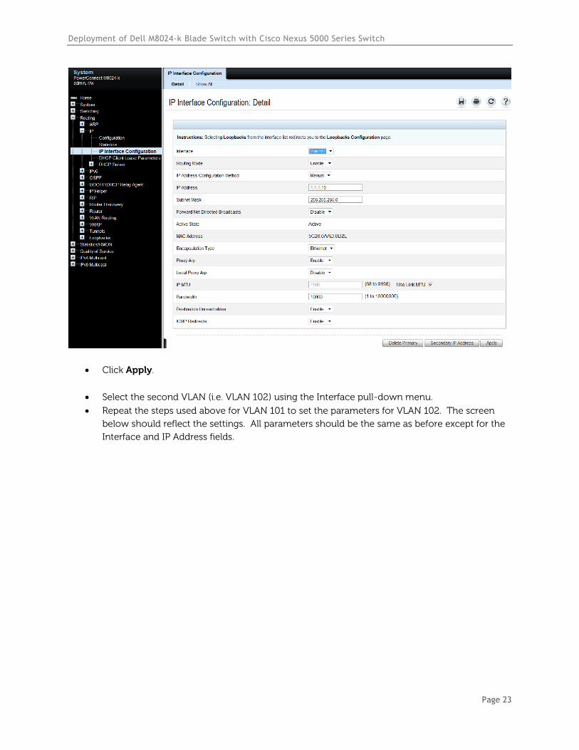
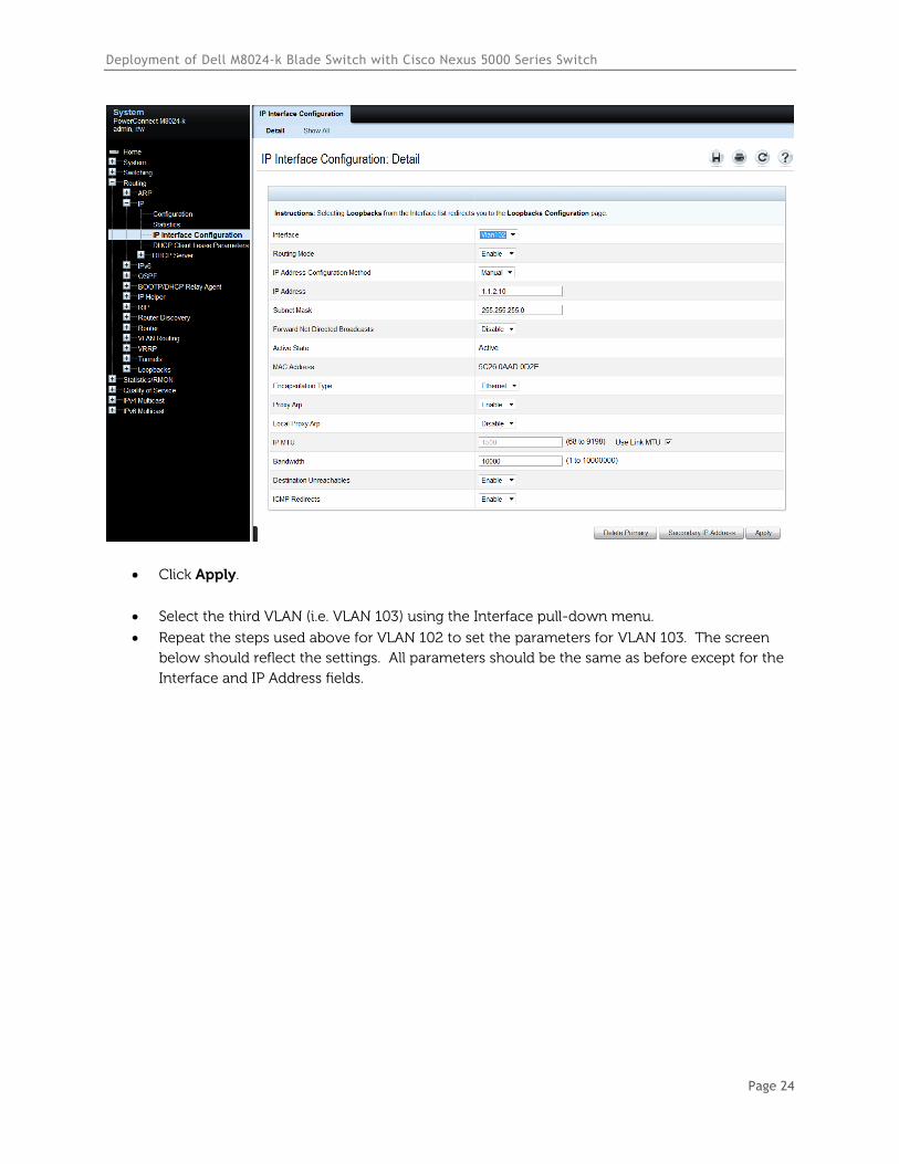
Select Routing>IP>IP Interface Configuration.
Select the first VLAN (i.e. VLAN 101) using the Interface pull-down menu.
Set Routing Mode to Enable.
Set IP address Configuration Method to Manual.
Provide the IP Address (i.e. 1.1.1.10) in the appropriate field.
Set the appropriate Subnet Mask (i.e. 255.255.255.0)
Set the IP MTU and Bandwidth parameters to appropriate sizes.
Deployment of Dell M8024-k Blade Switch with Cisco Nexus 5000 Series Switch
Page 23
Click Apply.
Select the second VLAN (i.e. VLAN 102) using the Interface pull-down menu.
Repeat the steps used above for VLAN 101 to set the parameters for VLAN 102. The screen
below should reflect the settings. All parameters should be the same as before except for the
Interface and IP Address fields.
Deployment of Dell M8024-k Blade Switch with Cisco Nexus 5000 Series Switch
Page 24
Click Apply.
Select the third VLAN (i.e. VLAN 103) using the Interface pull-down menu.
Repeat the steps used above for VLAN 102 to set the parameters for VLAN 103. The screen
below should reflect the settings. All parameters should be the same as before except for the
Interface and IP Address fields.

Deployment of Dell M8024-k Blade Switch with Cisco Nexus 5000 Series Switch
Page 25
Click Apply.
Configuring the Cisco 5020 Switch
Login to the Cisco Nexus 5020 and make the following changes using the CLI:
Nexus5020# configure
Enter configuration commands, one per line. End with CNTL/Z.
Nexus5020(config)# feature lacp
Nexus5020(config)# vlan 101-103
Nexus5020(config-vlan)# exit
Nexus5020(config)# interface ethernet 1/1-4
Nexus5020(config-if-range)# channel-group 1 mode active
Nexus5020(config-if-range)# exit
Nexus5020(config)# interface port-channel 1
Nexus5020(config-if)# switchport mode trunk
Nexus5020(config-if)# switchport trunk allowed vlan 101-103
Nexus5020(config-if)# exit
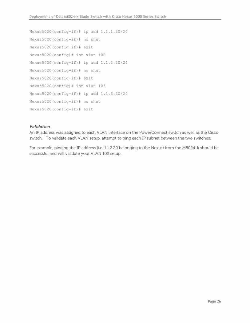
Nexus5020(config)# int vlan 101
Deployment of Dell M8024-k Blade Switch with Cisco Nexus 5000 Series Switch
Page 26
Nexus5020(config-if)# ip add 1.1.1.20/24
Nexus5020(config-if)# no shut
Nexus5020(config-if)# exit
Nexus5020(config)# int vlan 102
Nexus5020(config-if)# ip add 1.1.2.20/24
Nexus5020(config-if)# no shut
Nexus5020(config-if)# exit
Nexus5020(config)# int vlan 103
Nexus5020(config-if)# ip add 1.1.3.20/24
Nexus5020(config-if)# no shut
Nexus5020(config-if)# exit
Validation
An IP address was assigned to each VLAN interface on the PowerConnect switch as well as the Cisco
switch. To validate each VLAN setup, attempt to ping each IP subnet between the two switches.
For example, pinging the IP address (i.e. 1.1.2.20 belonging to the Nexus) from the M8024-k should be
successful and will validate your VLAN 102 setup.
Deployment of Dell M8024-k Blade Switch with Cisco Nexus 5000 Series Switch
Page 27
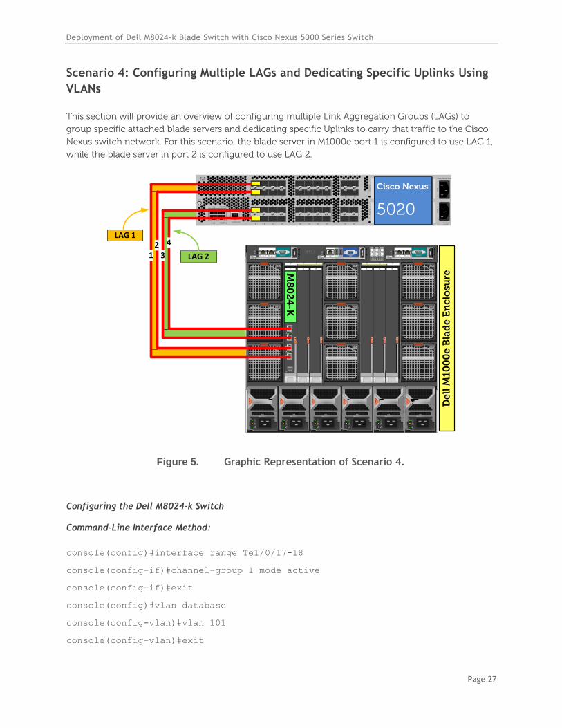
Scenario 4: Configuring Multiple LAGs and Dedicating Specific Uplinks Using
VLANs
This section will provide an overview of configuring multiple Link Aggregation Groups (LAGs) to
group specific attached blade servers and dedicating specific Uplinks to carry that traffic to the Cisco
Nexus switch network. For this scenario, the blade server in M1000e port 1 is configured to use LAG 1,
while the blade server in port 2 is configured to use LAG 2.
`STAT
CONSOLE
L1
L2
MGMT 0
MGMT 14 8 12 16
3 7 11 15
2 6 10 14
1 5 9 13
20 24 28 32
19 23 27 31
18 22 26 30
17 21 25 29
SLO
T2
34 38
33 37
36 40
35 39
SLO
T3
Cisco Nexus 5020
PS
1P
S2
200-240v-6A50~60Hz
De
ll M
10
00
e B
lad
e E
nc
losu
re
B2C2 A2B1 C1A1
4
1
7
5
2
8
6
3
9
CMC2CMC1 KVM
1 2 3 4 5 6
GbGb 21
CMC
iKVM
GbGb 21
CMC
12
34
CONSOLE
Po
we
rC
on
ne
ct M
80
24
-k
17
18
19
20
M8
02
4-K
12
3
4
Cisco Nexus
5020
LAG 2
LAG 1
Figure 5. Graphic Representation of Scenario 4.
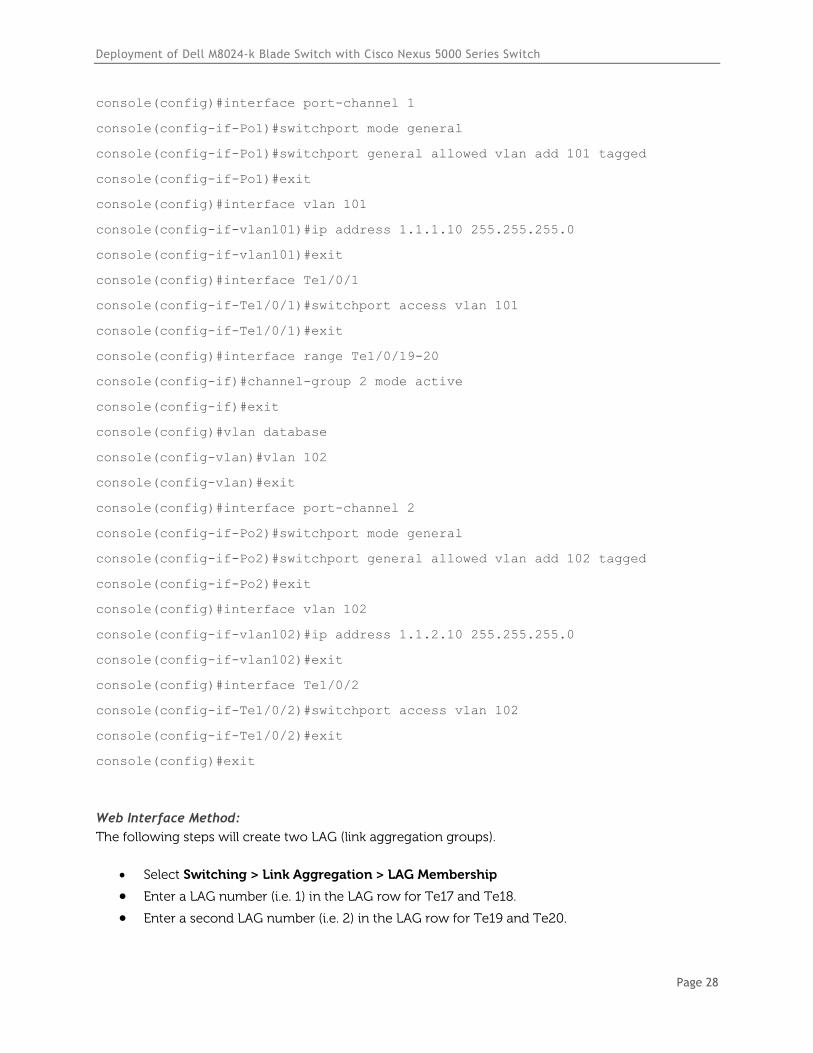
Configuring the Dell M8024-k Switch
Command-Line Interface Method:
console(config)#interface range Te1/0/17-18
console(config-if)#channel-group 1 mode active
console(config-if)#exit
console(config)#vlan database
console(config-vlan)#vlan 101
console(config-vlan)#exit
Deployment of Dell M8024-k Blade Switch with Cisco Nexus 5000 Series Switch
Page 28
console(config)#interface port-channel 1
console(config-if-Po1)#switchport mode general
console(config-if-Po1)#switchport general allowed vlan add 101 tagged
console(config-if-Po1)#exit
console(config)#interface vlan 101
console(config-if-vlan101)#ip address 1.1.1.10 255.255.255.0
console(config-if-vlan101)#exit
console(config)#interface Te1/0/1
console(config-if-Te1/0/1)#switchport access vlan 101
console(config-if-Te1/0/1)#exit
console(config)#interface range Te1/0/19-20
console(config-if)#channel-group 2 mode active
console(config-if)#exit
console(config)#vlan database
console(config-vlan)#vlan 102
console(config-vlan)#exit
console(config)#interface port-channel 2
console(config-if-Po2)#switchport mode general
console(config-if-Po2)#switchport general allowed vlan add 102 tagged
console(config-if-Po2)#exit
console(config)#interface vlan 102
console(config-if-vlan102)#ip address 1.1.2.10 255.255.255.0
console(config-if-vlan102)#exit
console(config)#interface Te1/0/2
console(config-if-Te1/0/2)#switchport access vlan 102
console(config-if-Te1/0/2)#exit
console(config)#exit
Web Interface Method:
The following steps will create two LAG (link aggregation groups).
Select Switching > Link Aggregation > LAG Membership
Enter a LAG number (i.e. 1) in the LAG row for Te17 and Te18.
Enter a second LAG number (i.e. 2) in the LAG row for Te19 and Te20.
Deployment of Dell M8024-k Blade Switch with Cisco Nexus 5000 Series Switch
Page 29
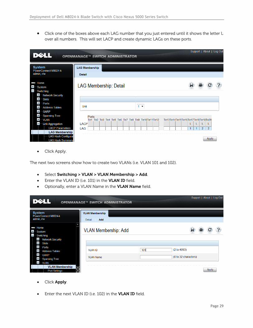
Click one of the boxes above each LAG number that you just entered until it shows the letter L
over all numbers. This will set LACP and create dynamic LAGs on these ports.
Click Apply.
The next two screens show how to create two VLANs (i.e. VLAN 101 and 102).
Select Switching > VLAN > VLAN Membership > Add.
Enter the VLAN ID (i.e. 101) in the VLAN ID field.
Optionally, enter a VLAN Name in the VLAN Name field.
Click Apply.
Enter the next VLAN ID (i.e. 102) in the VLAN ID field.
Deployment of Dell M8024-k Blade Switch with Cisco Nexus 5000 Series Switch
Page 30
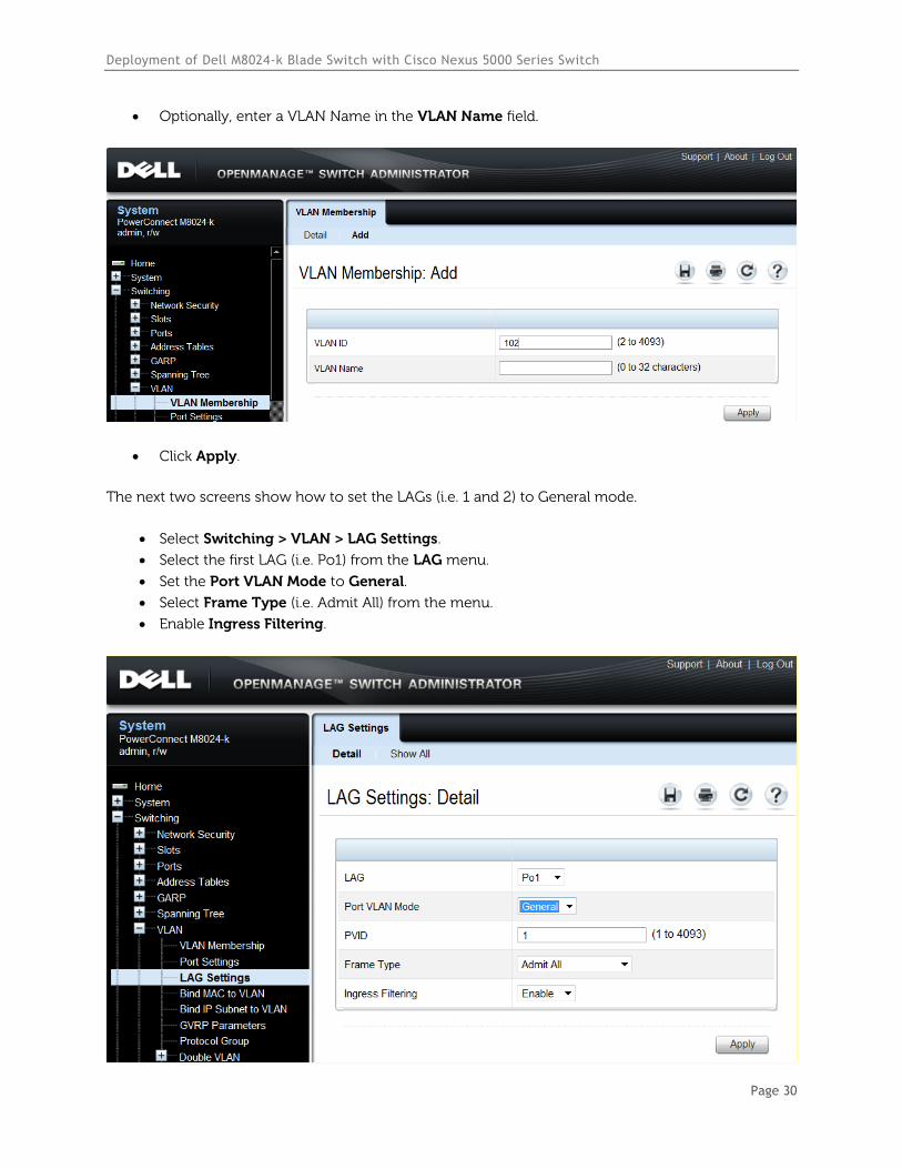
Optionally, enter a VLAN Name in the VLAN Name field.
Click Apply.
The next two screens show how to set the LAGs (i.e. 1 and 2) to General mode.
Select Switching > VLAN > LAG Settings.
Select the first LAG (i.e. Po1) from the LAG menu.
Set the Port VLAN Mode to General.
Select Frame Type (i.e. Admit All) from the menu.
Enable Ingress Filtering.
Deployment of Dell M8024-k Blade Switch with Cisco Nexus 5000 Series Switch
Page 31
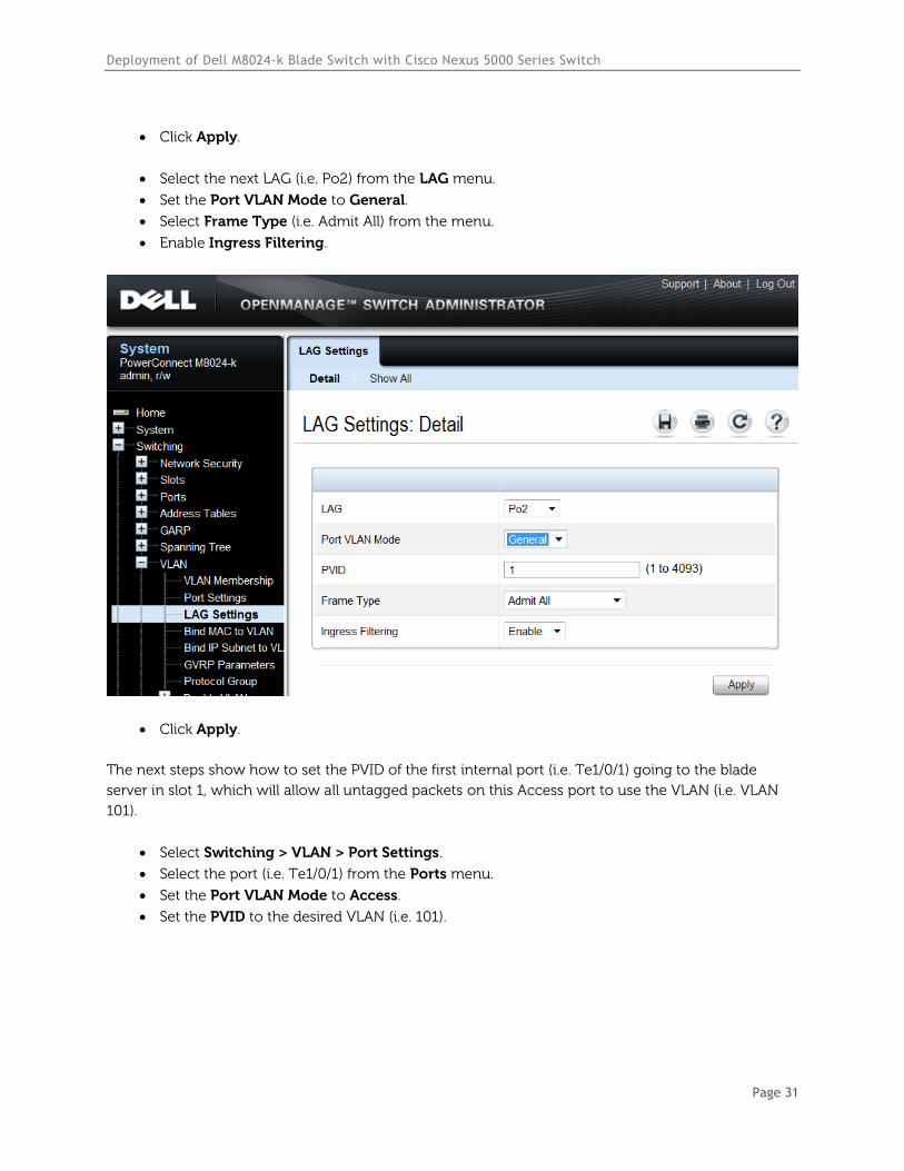
Click Apply.
Select the next LAG (i.e. Po2) from the LAG menu.
Set the Port VLAN Mode to General.
Select Frame Type (i.e. Admit All) from the menu.
Enable Ingress Filtering.
Click Apply.
The next steps show how to set the PVID of the first internal port (i.e. Te1/0/1) going to the blade
server in slot 1, which will allow all untagged packets on this Access port to use the VLAN (i.e. VLAN
101).
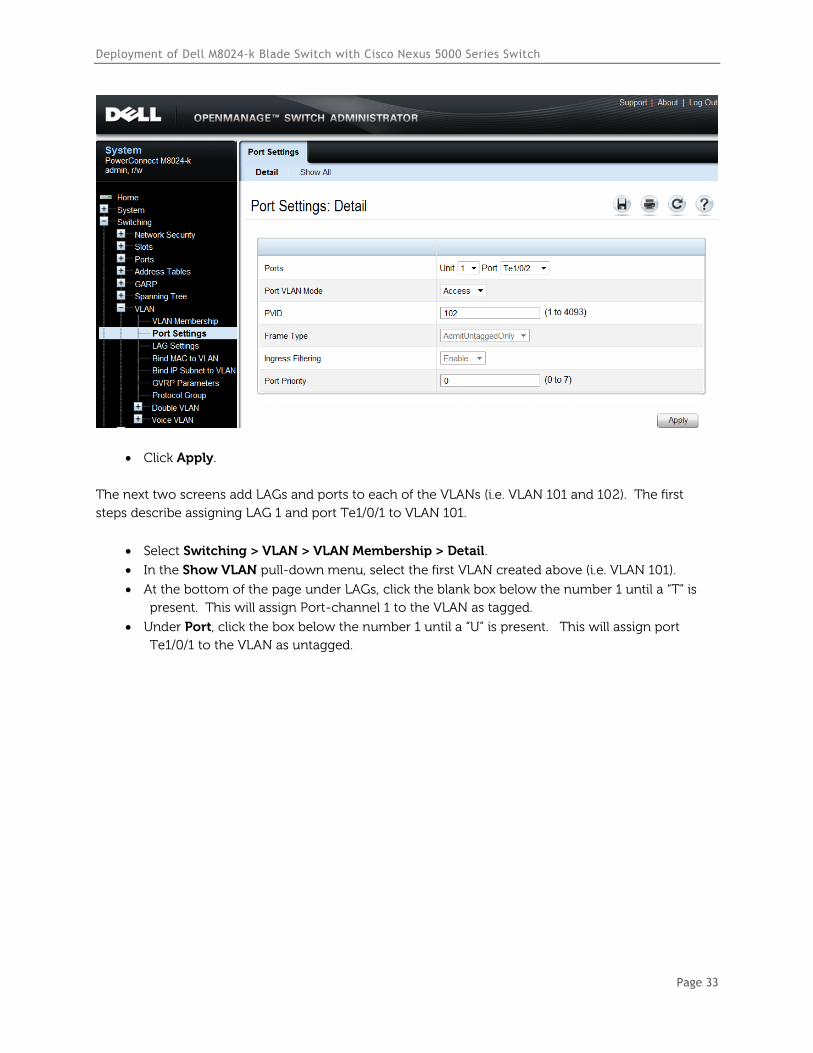
Select Switching > VLAN > Port Settings.
Select the port (i.e. Te1/0/1) from the Ports menu.
Set the Port VLAN Mode to Access.
Set the PVID to the desired VLAN (i.e. 101).
Deployment of Dell M8024-k Blade Switch with Cisco Nexus 5000 Series Switch
Page 32
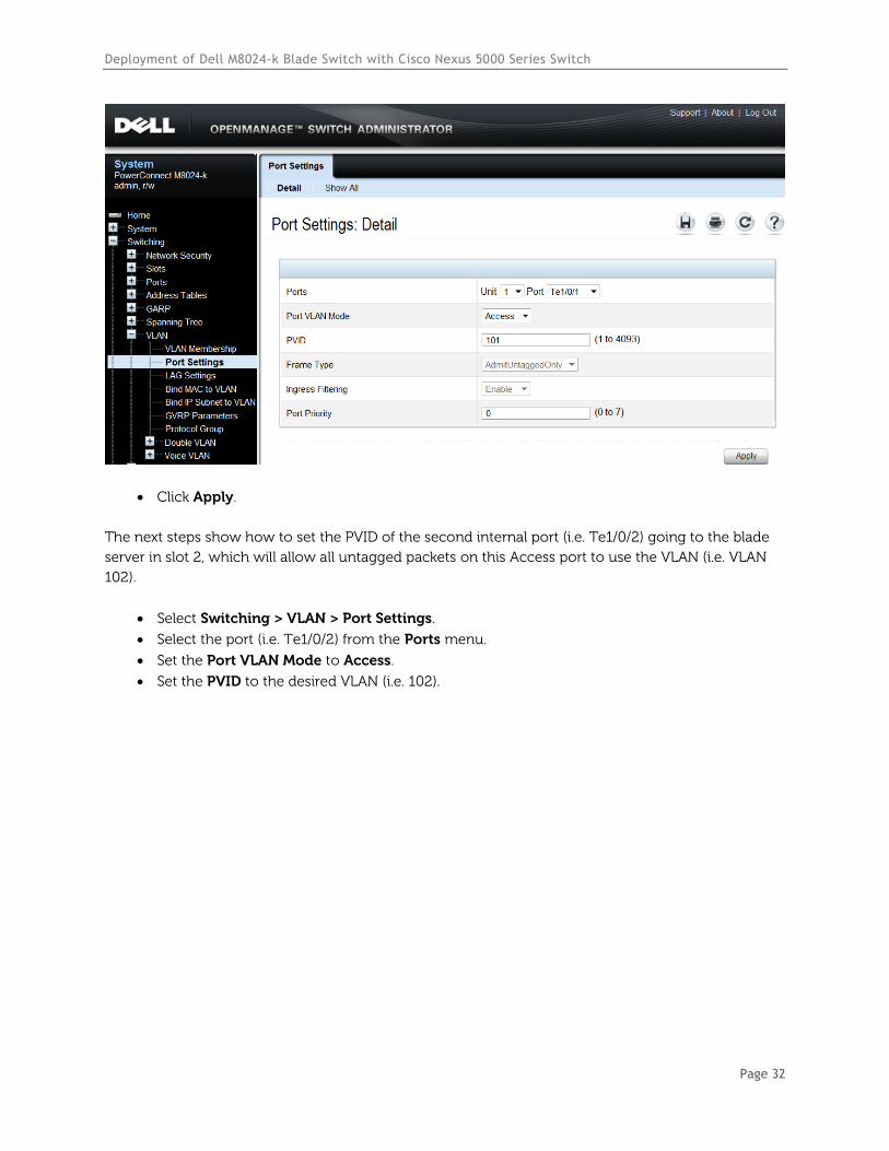
Click Apply.
The next steps show how to set the PVID of the second internal port (i.e. Te1/0/2) going to the blade
server in slot 2, which will allow all untagged packets on this Access port to use the VLAN (i.e. VLAN
102).
Select Switching > VLAN > Port Settings.
Select the port (i.e. Te1/0/2) from the Ports menu.
Set the Port VLAN Mode to Access.
Set the PVID to the desired VLAN (i.e. 102).
Deployment of Dell M8024-k Blade Switch with Cisco Nexus 5000 Series Switch
Page 33
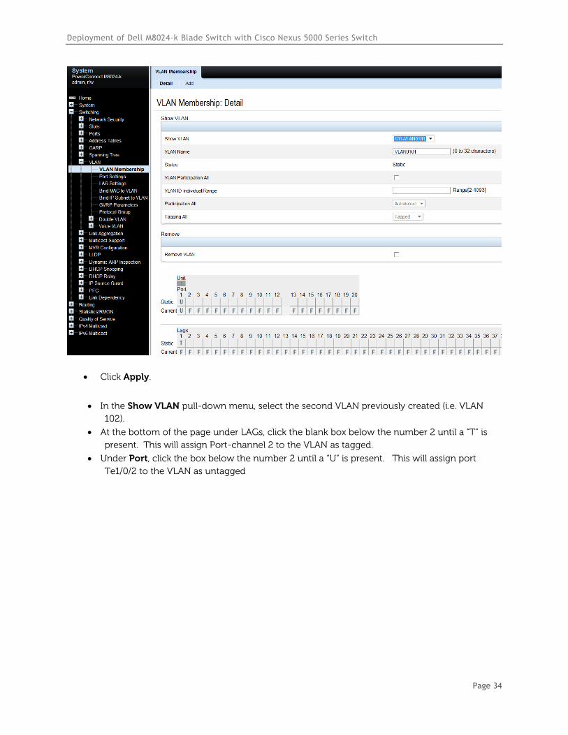
Click Apply.
The next two screens add LAGs and ports to each of the VLANs (i.e. VLAN 101 and 102). The first
steps describe assigning LAG 1 and port Te1/0/1 to VLAN 101.
Select Switching > VLAN > VLAN Membership > Detail.
In the Show VLAN pull-down menu, select the first VLAN created above (i.e. VLAN 101).
At the bottom of the page under LAGs, click the blank box below the number 1 until a “T” is
present. This will assign Port-channel 1 to the VLAN as tagged.
Under Port, click the box below the number 1 until a “U” is present. This will assign port
Te1/0/1 to the VLAN as untagged.
Deployment of Dell M8024-k Blade Switch with Cisco Nexus 5000 Series Switch
Page 34
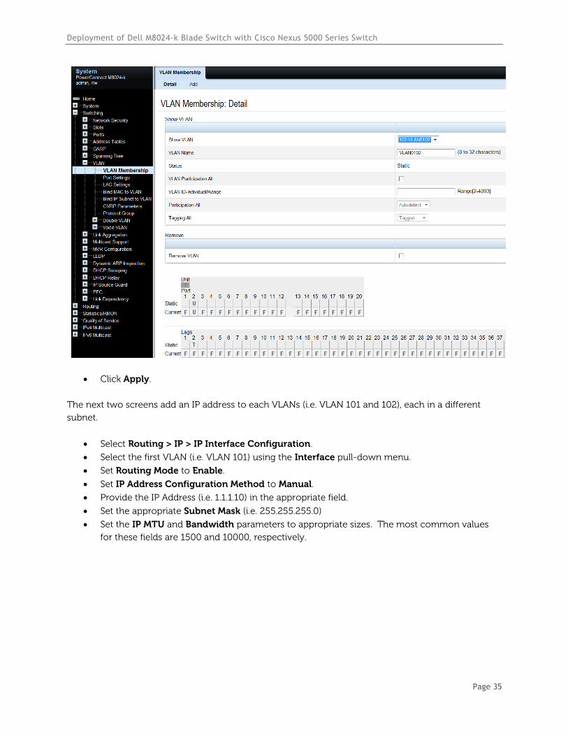
Click Apply.
In the Show VLAN pull-down menu, select the second VLAN previously created (i.e. VLAN
102).
At the bottom of the page under LAGs, click the blank box below the number 2 until a “T” is
present. This will assign Port-channel 2 to the VLAN as tagged.
Under Port, click the box below the number 2 until a “U” is present. This will assign port
Te1/0/2 to the VLAN as untagged
Deployment of Dell M8024-k Blade Switch with Cisco Nexus 5000 Series Switch
Page 35
Click Apply.
The next two screens add an IP address to each VLANs (i.e. VLAN 101 and 102), each in a different
subnet.
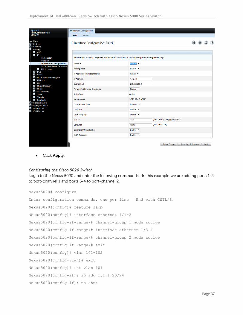
Select Routing > IP > IP Interface Configuration.
Select the first VLAN (i.e. VLAN 101) using the Interface pull-down menu.
Set Routing Mode to Enable.
Set IP Address Configuration Method to Manual.
Provide the IP Address (i.e. 1.1.1.10) in the appropriate field.
Set the appropriate Subnet Mask (i.e. 255.255.255.0)
Set the IP MTU and Bandwidth parameters to appropriate sizes. The most common values
for these fields are 1500 and 10000, respectively.

Deployment of Dell M8024-k Blade Switch with Cisco Nexus 5000 Series Switch
Page 36
Click Apply.
Select the second VLAN (i.e. VLAN 102) using the Interface pull-down menu.
Repeat the steps used above for VLAN 101 to set the parameters for VLAN 102. The screen
below should reflect the settings. All parameters should be the same as before except for the
Interface and IP Address fields.
Deployment of Dell M8024-k Blade Switch with Cisco Nexus 5000 Series Switch
Page 37
Click Apply.
Configuring the Cisco 5020 Switch
Login to the Nexus 5020 and enter the following commands. In this example we are adding ports 1-2
to port-channel 1 and ports 3-4 to port-channel 2.
Nexus5020# configure
Enter configuration commands, one per line. End with CNTL/Z.
Nexus5020(config)# feature lacp
Nexus5020(config)# interface ethernet 1/1-2
Nexus5020(config-if-range)# channel-group 1 mode active
Nexus5020(config-if-range)# interface ethernet 1/3-4
Nexus5020(config-if-range)# channel-group 2 mode active
Nexus5020(config-if-range)# exit
Nexus5020(config)# vlan 101-102
Nexus5020(config-vlan)# exit
Nexus5020(config)# int vlan 101
Nexus5020(config-if)# ip add 1.1.1.20/24
Nexus5020(config-if)# no shut
Deployment of Dell M8024-k Blade Switch with Cisco Nexus 5000 Series Switch
Page 38
Nexus5020(config-if)# exit
Nexus5020(config)# int vlan 102
Nexus5020(config-if)# ip add 1.1.2.20/24
Nexus5020(config-if)# no shut
Nexus5020(config-if)# exit
Nexus5020(config)# interface port-channel1
Nexus5020(config-if)# switchport mode trunk
Nexus5020(config-if)# switchport trunk allowed vlan 101
Nexus5020(config-if)# exit
Nexus5020(config)# interface port-channel2
Nexus5020(config-if)# switchport mode trunk
Nexus5020(config-if)# switchport trunk allowed vlan 102
Nexus5020(config-if)# end
Validation
An IP address was assigned to each VLAN interface on the PowerConnect switch as well as the Cisco
switch. To validate each VLAN setup, attempt to ping each IP subnet between the two switches.
For example, pinging the IP address (i.e. 1.1.2.20 belonging to the Nexus) from the M8024-k should be
successful and will validate the VLAN 102 setup.
It is also possible to validate the entire path from the Cisco Nexus to the blade server, going through
the PowerConnect M8024-k switch. In the example above the following lines were added to the
M8024-k that put blade server traffic on slot 1 onto VLAN 101.
console(config)#interface Te1/0/1
console(config-if-Te1/0/1)#switchport access vlan 101
By now adding an IP address to the server NIC (i.e. 1.1.1.5), it is possible to ping the server from the
M8024-k as well as from the Cisco Nexus.
Deployment of Dell M8024-k Blade Switch with Cisco Nexus 5000 Series Switch
Page 39
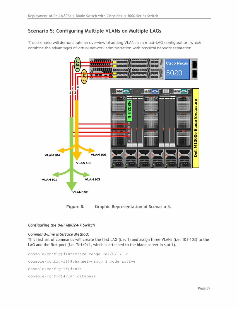
Scenario 5: Configuring Multiple VLANs on Multiple LAGs
This scenario will demonstrate an overview of adding VLANs in a multi-LAG configuration, which
combine the advantages of virtual network administration with physical network separation.
`STAT
CONSOLE
L1
L2
MGMT 0
MGMT 14 8 12 16
3 7 11 15
2 6 10 14
1 5 9 13
20 24 28 32
19 23 27 31
18 22 26 30
17 21 25 29
SLO
T2
34 38
33 37
36 40
35 39
SLO
T3
Cisco Nexus 5020
PS
1P
S2
200-240v-6A50~60Hz
De
ll M
10
00
e B
lad
e E
nc
losu
re
B2C2 A2B1 C1A1
4
1
7
5
2
8
6
3
9
CMC2CMC1 KVM
1 2 3 4 5 6
GbGb 21
CMC
iKVM
GbGb 21
CMC
12
34
CONSOLE
Po
we
rC
on
ne
ct M
80
24
-k
17
18
19
20
M8
02
4-K
12
3
4
Cisco Nexus
5020
LAG
2
VLAN 105
VLAN 106VLAN 104
VLAN 103
VLAN 102
VLAN 101
LAG
1
Figure 6. Graphic Representation of Scenario 5.
Configuring the Dell M8024-k Switch
Command-Line Interface Method:
This first set of commands will create the first LAG (i.e. 1) and assign three VLANs (i.e. 101-103) to the
LAG and the first port (i.e. Te1/0/1, which is attached to the blade server in slot 1).
console(config)#interface range Te1/0/17-18
console(config-if)#channel-group 1 mode active
console(config-if)#exit
console(config)#vlan database
Deployment of Dell M8024-k Blade Switch with Cisco Nexus 5000 Series Switch
Page 40
console(config-vlan)#vlan 101-103
console(config-vlan)#exit
console(config)#interface port-channel 1
console(config-if-Po1)#switchport mode general
console(config-if-Po1)#switchport general allowed vlan add 101-103 tagged
console(config-if-Po1)#exit
console(config)#interface vlan 101
console(config-if-vlan101)#ip address 1.1.1.10 255.255.255.0
console(config-if-vlan101)#exit
console(config)#interface vlan 102
console(config-if-vlan102)#ip address 1.1.2.10 255.255.255.0
console(config-if-vlan102)#exit
console(config)#interface vlan 103
console(config-if-vlan103)#ip address 1.1.3.10 255.255.255.0
console(config-if-vlan103)#exit
console(config)#interface Te1/0/1
console(config-if-Te1/0/1)#switchport general allowed vlan add 101-103 tagged
console(config-if-Te1/0/1)#exit
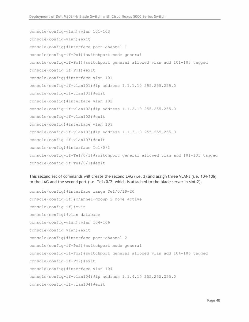
This second set of commands will create the second LAG (i.e. 2) and assign three VLANs (i.e. 104-106)
to the LAG and the second port (i.e. Te1/0/2, which is attached to the blade server in slot 2).
console(config)#interface range Te1/0/19-20
console(config-if)#channel-group 2 mode active
console(config-if)#exit
console(config)#vlan database
console(config-vlan)#vlan 104-106
console(config-vlan)#exit
console(config)#interface port-channel 2
console(config-if-Po2)#switchport mode general
console(config-if-Po2)#switchport general allowed vlan add 104-106 tagged
console(config-if-Po2)#exit
console(config)#interface vlan 104
console(config-if-vlan104)#ip address 1.1.4.10 255.255.255.0
console(config-if-vlan104)#exit
Deployment of Dell M8024-k Blade Switch with Cisco Nexus 5000 Series Switch
Page 41
console(config)#interface vlan 105
console(config-if-vlan105)#ip address 1.1.5.10 255.255.255.0
console(config-if-vlan105)#exit
console(config)#interface vlan 106
console(config-if-vlan106)#ip address 1.1.6.10 255.255.255.0
console(config-if-vlan106)#exit
console(config)#interface Te1/0/2
console(config-if-Te1/0/2)#switchport general allowed vlan add 104-106 tagged
console(config-if-Te1/0/2)#exit
console(config)#exit
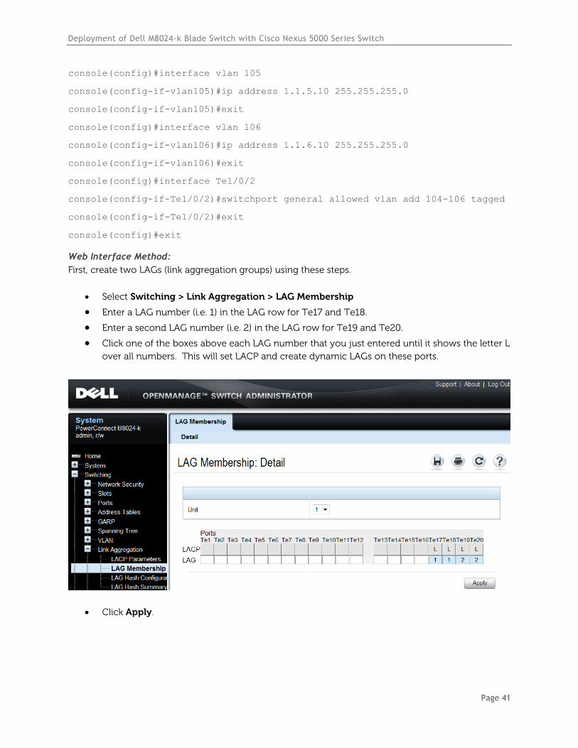
Web Interface Method:
First, create two LAGs (link aggregation groups) using these steps.
Select Switching > Link Aggregation > LAG Membership
Enter a LAG number (i.e. 1) in the LAG row for Te17 and Te18.
Enter a second LAG number (i.e. 2) in the LAG row for Te19 and Te20.
Click one of the boxes above each LAG number that you just entered until it shows the letter L
over all numbers. This will set LACP and create dynamic LAGs on these ports.
Click Apply.
Deployment of Dell M8024-k Blade Switch with Cisco Nexus 5000 Series Switch
Page 42
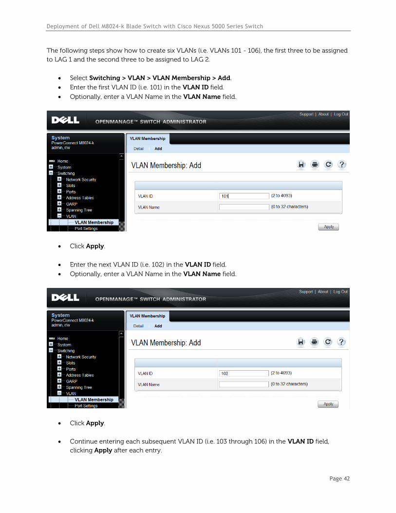
The following steps show how to create six VLANs (i.e. VLANs 101 - 106), the first three to be assigned
to LAG 1 and the second three to be assigned to LAG 2.
Select Switching > VLAN > VLAN Membership > Add.
Enter the first VLAN ID (i.e. 101) in the VLAN ID field.
Optionally, enter a VLAN Name in the VLAN Name field.
Click Apply.
Enter the next VLAN ID (i.e. 102) in the VLAN ID field.
Optionally, enter a VLAN Name in the VLAN Name field.
Click Apply.
Continue entering each subsequent VLAN ID (i.e. 103 through 106) in the VLAN ID field,
clicking Apply after each entry.
Deployment of Dell M8024-k Blade Switch with Cisco Nexus 5000 Series Switch
Page 43
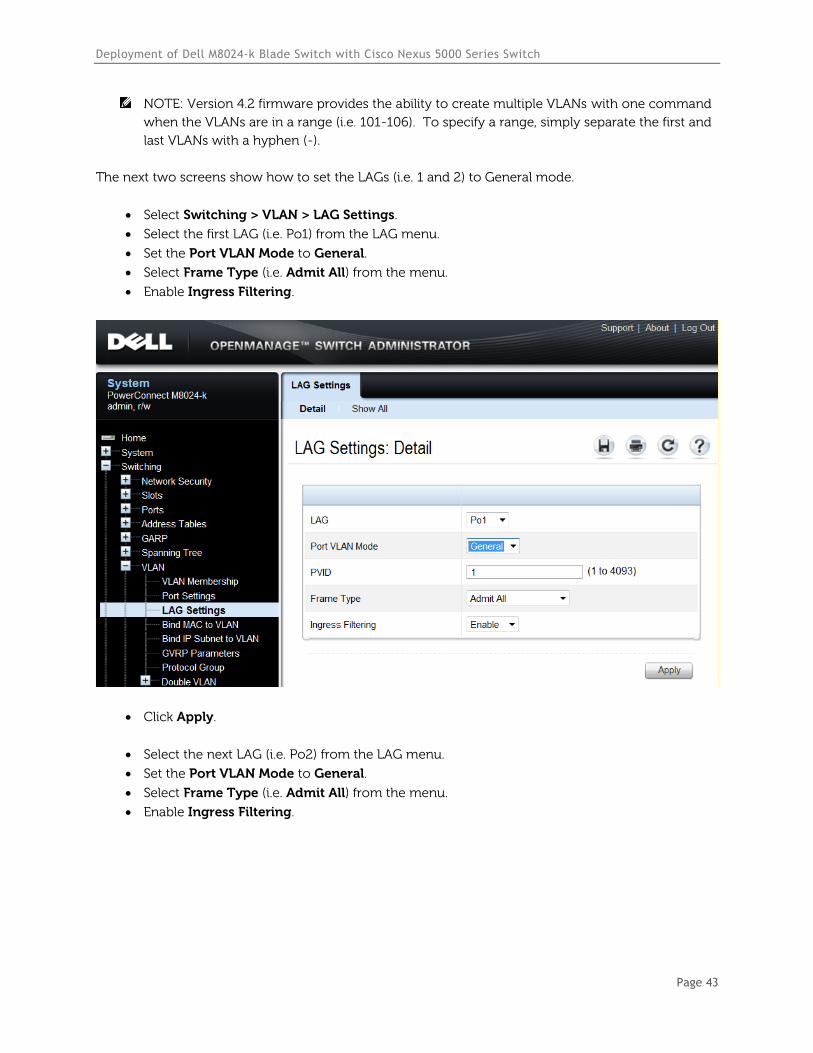
NOTE: Version 4.2 firmware provides the ability to create multiple VLANs with one command
when the VLANs are in a range (i.e. 101-106). To specify a range, simply separate the first and
last VLANs with a hyphen (-).
The next two screens show how to set the LAGs (i.e. 1 and 2) to General mode.
Select Switching > VLAN > LAG Settings.
Select the first LAG (i.e. Po1) from the LAG menu.
Set the Port VLAN Mode to General.
Select Frame Type (i.e. Admit All) from the menu.
Enable Ingress Filtering.
Click Apply.
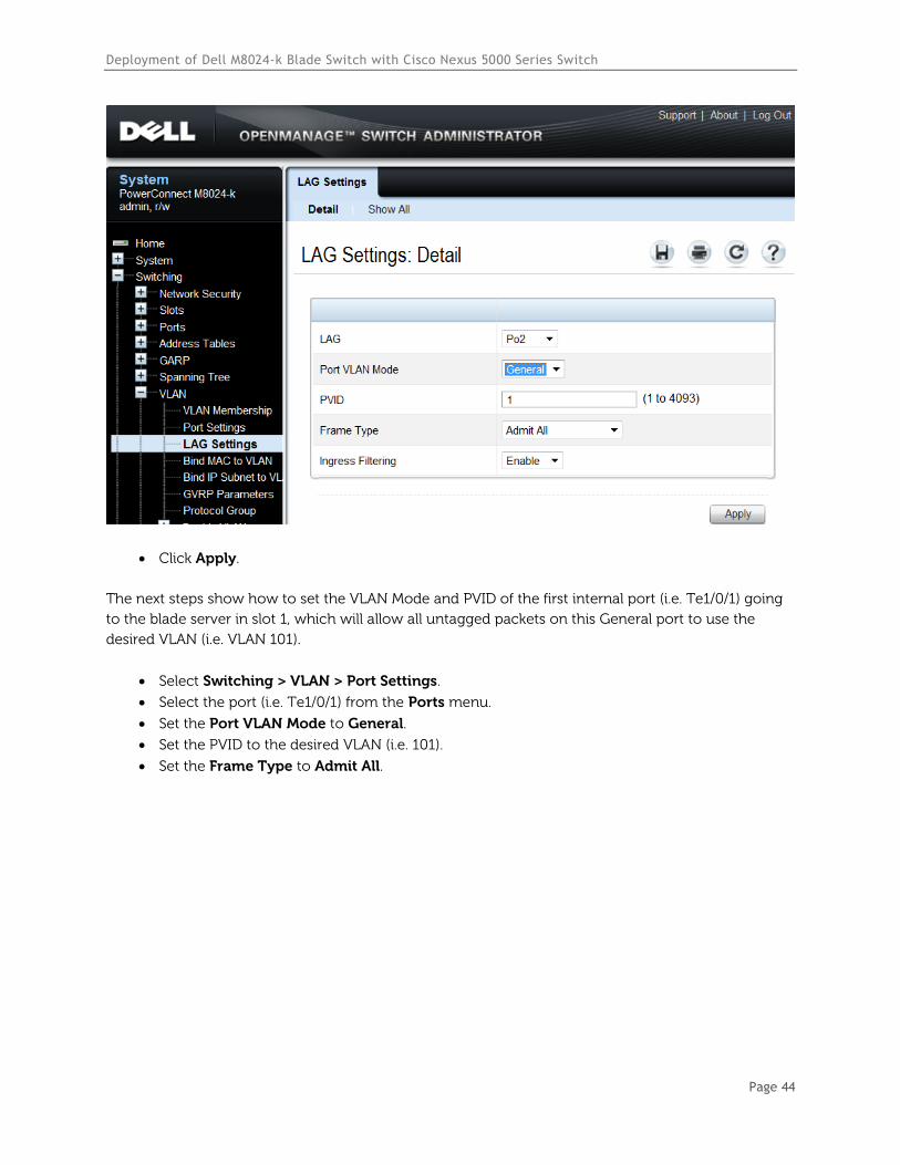
Select the next LAG (i.e. Po2) from the LAG menu.
Set the Port VLAN Mode to General.
Select Frame Type (i.e. Admit All) from the menu.
Enable Ingress Filtering.
Deployment of Dell M8024-k Blade Switch with Cisco Nexus 5000 Series Switch
Page 44
Click Apply.
The next steps show how to set the VLAN Mode and PVID of the first internal port (i.e. Te1/0/1) going
to the blade server in slot 1, which will allow all untagged packets on this General port to use the
desired VLAN (i.e. VLAN 101).
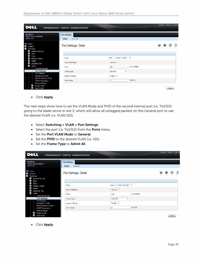
Select Switching > VLAN > Port Settings.
Select the port (i.e. Te1/0/1) from the Ports menu.
Set the Port VLAN Mode to General.
Set the PVID to the desired VLAN (i.e. 101).
Set the Frame Type to Admit All.
Deployment of Dell M8024-k Blade Switch with Cisco Nexus 5000 Series Switch
Page 45
Click Apply.
The next steps show how to set the VLAN Mode and PVID of the second internal port (i.e. Te1/0/2)
going to the blade server in slot 2, which will allow all untagged packets on this General port to use
the desired VLAN (i.e. VLAN 102).
Select Switching > VLAN > Port Settings.
Select the port (i.e. Te1/0/2) from the Ports menu.
Set the Port VLAN Mode to General.
Set the PVID to the desired VLAN (i.e. 102).
Set the Frame Type to Admit All.
Click Apply.
Deployment of Dell M8024-k Blade Switch with Cisco Nexus 5000 Series Switch
Page 46
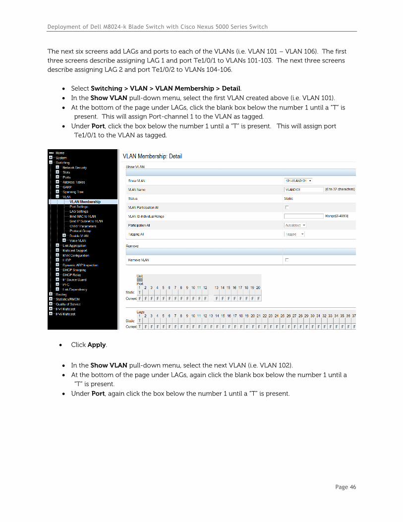
The next six screens add LAGs and ports to each of the VLANs (i.e. VLAN 101 – VLAN 106). The first
three screens describe assigning LAG 1 and port Te1/0/1 to VLANs 101-103. The next three screens
describe assigning LAG 2 and port Te1/0/2 to VLANs 104-106.
Select Switching > VLAN > VLAN Membership > Detail.
In the Show VLAN pull-down menu, select the first VLAN created above (i.e. VLAN 101).
At the bottom of the page under LAGs, click the blank box below the number 1 until a “T” is
present. This will assign Port-channel 1 to the VLAN as tagged.
Under Port, click the box below the number 1 until a “T” is present. This will assign port
Te1/0/1 to the VLAN as tagged.
Click Apply.
In the Show VLAN pull-down menu, select the next VLAN (i.e. VLAN 102).
At the bottom of the page under LAGs, again click the blank box below the number 1 until a
“T” is present.
Under Port, again click the box below the number 1 until a “T” is present.
Deployment of Dell M8024-k Blade Switch with Cisco Nexus 5000 Series Switch
Page 47
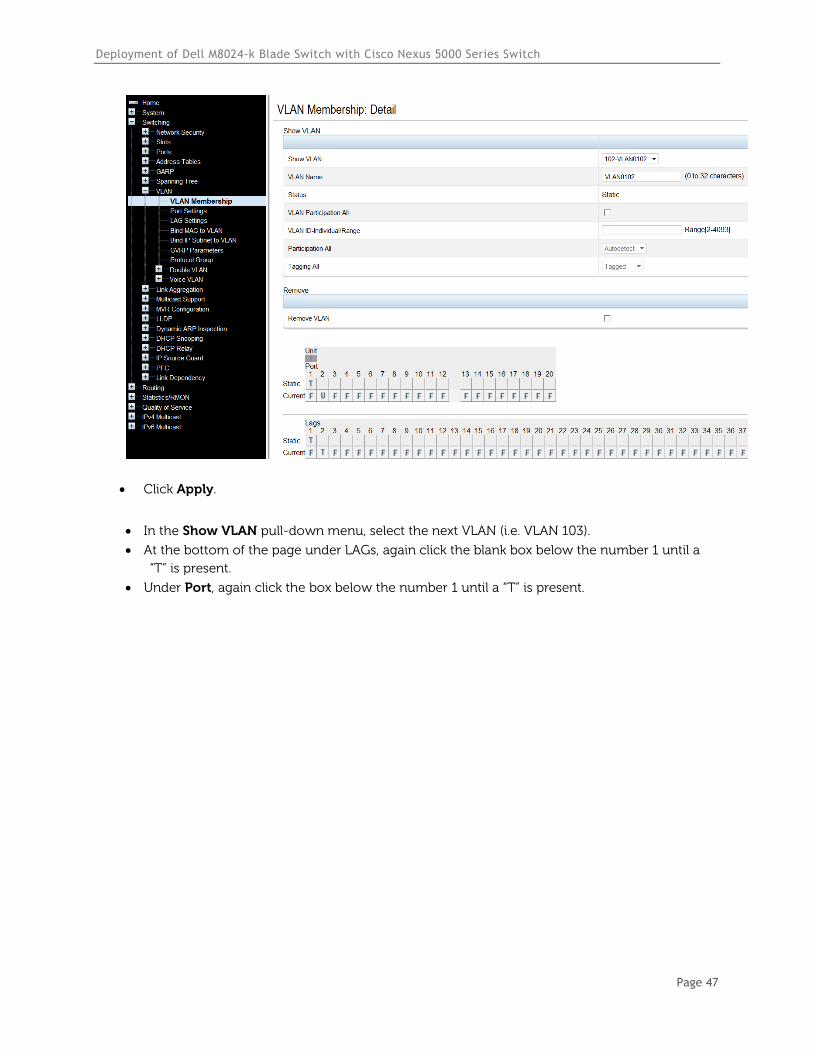
Click Apply.
In the Show VLAN pull-down menu, select the next VLAN (i.e. VLAN 103).
At the bottom of the page under LAGs, again click the blank box below the number 1 until a
“T” is present.
Under Port, again click the box below the number 1 until a “T” is present.
Deployment of Dell M8024-k Blade Switch with Cisco Nexus 5000 Series Switch
Page 48
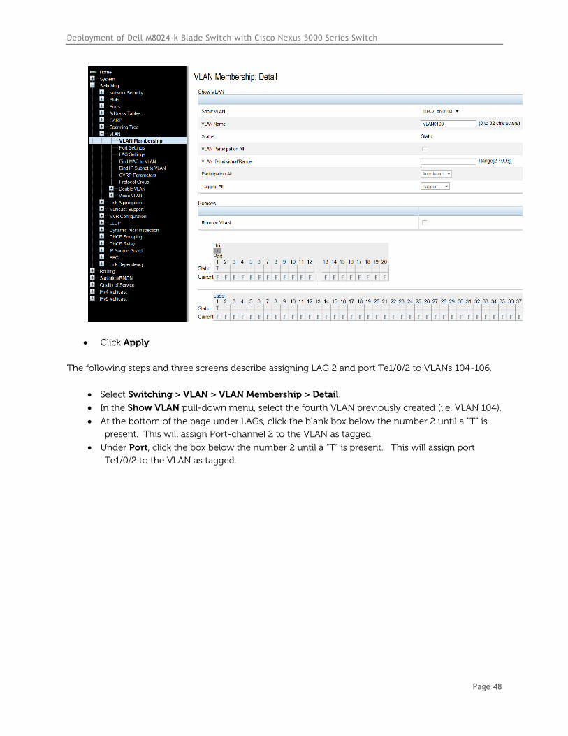
Click Apply.
The following steps and three screens describe assigning LAG 2 and port Te1/0/2 to VLANs 104-106.
Select Switching > VLAN > VLAN Membership > Detail.
In the Show VLAN pull-down menu, select the fourth VLAN previously created (i.e. VLAN 104).
At the bottom of the page under LAGs, click the blank box below the number 2 until a “T” is
present. This will assign Port-channel 2 to the VLAN as tagged.
Under Port, click the box below the number 2 until a “T” is present. This will assign port
Te1/0/2 to the VLAN as tagged.
Deployment of Dell M8024-k Blade Switch with Cisco Nexus 5000 Series Switch
Page 49
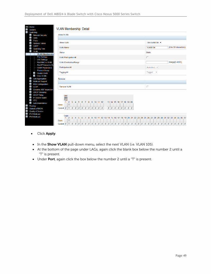
Click Apply.
In the Show VLAN pull-down menu, select the next VLAN (i.e. VLAN 105).
At the bottom of the page under LAGs, again click the blank box below the number 2 until a
“T” is present.
Under Port, again click the box below the number 2 until a “T” is present.
Deployment of Dell M8024-k Blade Switch with Cisco Nexus 5000 Series Switch
Page 50
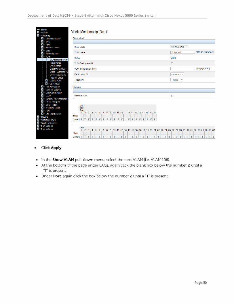
Click Apply.
In the Show VLAN pull-down menu, select the next VLAN (i.e. VLAN 106).
At the bottom of the page under LAGs, again click the blank box below the number 2 until a
“T” is present.
Under Port, again click the box below the number 2 until a “T” is present.
Deployment of Dell M8024-k Blade Switch with Cisco Nexus 5000 Series Switch
Page 51
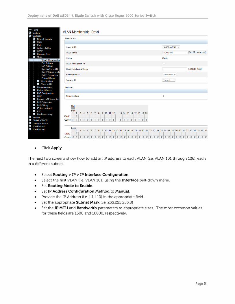
Click Apply.
The next two screens show how to add an IP address to each VLAN (i.e. VLAN 101 through 106), each
in a different subnet.
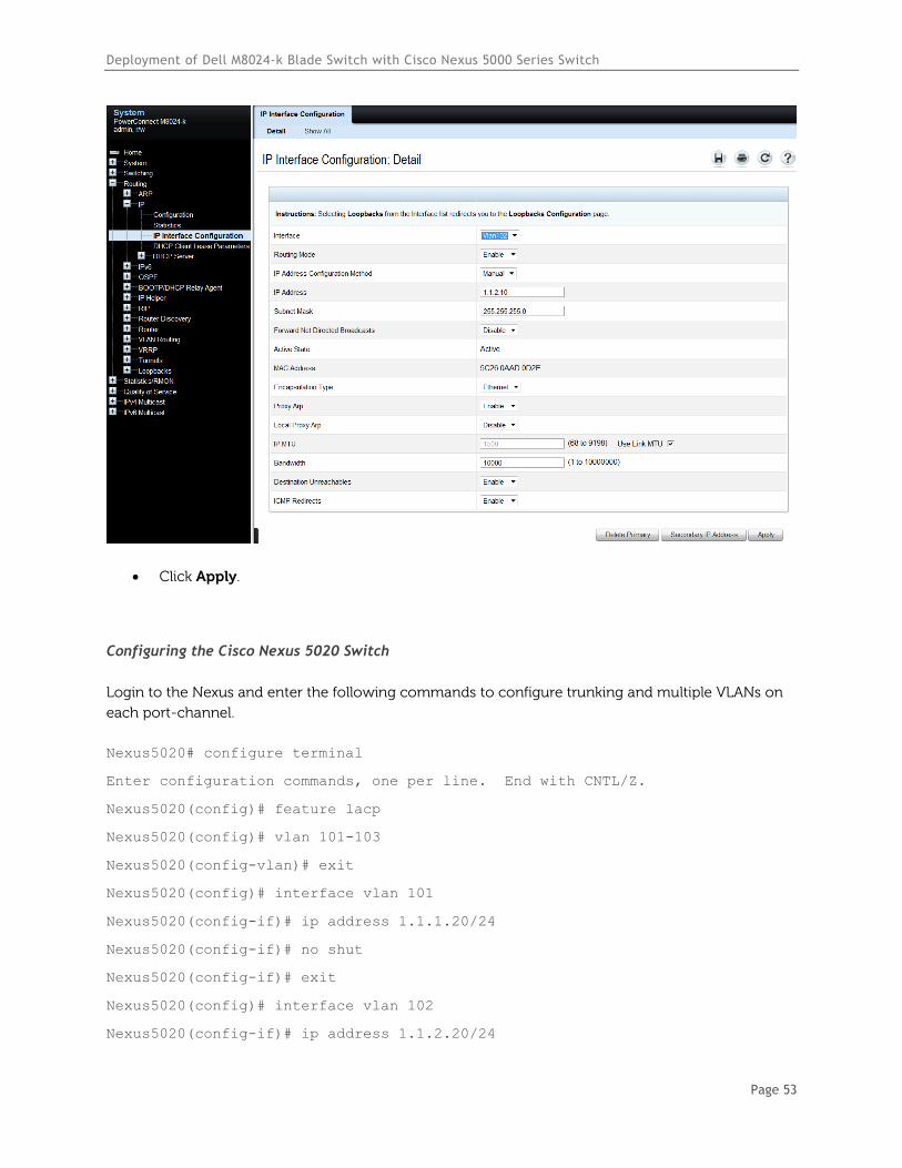
Select Routing > IP > IP Interface Configuration.
Select the first VLAN (i.e. VLAN 101) using the Interface pull-down menu.
Set Routing Mode to Enable.
Set IP Address Configuration Method to Manual.
Provide the IP Address (i.e. 1.1.1.10) in the appropriate field.
Set the appropriate Subnet Mask (i.e. 255.255.255.0)
Set the IP MTU and Bandwidth parameters to appropriate sizes. The most common values
for these fields are 1500 and 10000, respectively.

Deployment of Dell M8024-k Blade Switch with Cisco Nexus 5000 Series Switch
Page 52
Click Apply.
Select the second VLAN (i.e. VLAN 102) using the Interface pull-down menu.
Repeat the steps used above to set the parameters for each remaining VLAN (i.e. VLAN 102
through VLAN 106). For example, the screen below should reflect the settings for VLAN 102,
with an IP address of 1.1.2.10. All parameters should be the same as before except for the
Interface and IP Address fields.
Deployment of Dell M8024-k Blade Switch with Cisco Nexus 5000 Series Switch
Page 53
Click Apply.
Configuring the Cisco Nexus 5020 Switch
Login to the Nexus and enter the following commands to configure trunking and multiple VLANs on
each port-channel.
Nexus5020# configure terminal
Enter configuration commands, one per line. End with CNTL/Z.
Nexus5020(config)# feature lacp
Nexus5020(config)# vlan 101-103
Nexus5020(config-vlan)# exit
Nexus5020(config)# interface vlan 101
Nexus5020(config-if)# ip address 1.1.1.20/24
Nexus5020(config-if)# no shut
Nexus5020(config-if)# exit
Nexus5020(config)# interface vlan 102
Nexus5020(config-if)# ip address 1.1.2.20/24
Deployment of Dell M8024-k Blade Switch with Cisco Nexus 5000 Series Switch
Page 54
Nexus5020(config-if)# no shut
Nexus5020(config-if)# exit
Nexus5020(config)# interface vlan 103
Nexus5020(config-if)# ip add 1.1.3.20/24
Nexus5020(config-if)# no shut
Nexus5020(config-if)# exit
Nexus5020(config)# interface ethernet 1/1-2
Nexus5020(config-if-range)# switchport
Nexus5020(config-if-range)# channel-group 1 mode active
Nexus5020(config-if-range)# no shutdown
Nexus5020(config-if-range)# exit
Nexus5020(config)# interface port-channel 1
Nexus5020(config-if)# switchport
Nexus5020(config-if)# switchport trunk allowed vlan 101-103
Nexus5020(config-if)# switchport mode trunk
Nexus5020(config-if)# end
For this next set of commands a second Cisco Nexus could be used. However for this example, we’ll
continue using the same Nexus 5000 switch and simply use ports 3 and 4 for the next LAG group.
Nexus5020# configure terminal
Enter configuration commands, one per line. End with CNTL/Z.
Nexus5020(config)# feature lacp
Nexus5020(config)# vlan 104-106
Nexus5020(config-vlan)# exit
Nexus5020(config)# interface vlan 104
Nexus5020(config-if)# ip address 1.1.4.20/24
Nexus5020(config-if)# no shut
Nexus5020(config-if)# exit
Nexus5020(config)# interface vlan 105
Nexus5020(config-if)# ip address 1.1.5.20/24
Nexus5020(config-if)# no shut
Nexus5020(config-if)# exit
Nexus5020(config)# interface vlan 106
Nexus5020(config-if)# ip add 1.1.6.20/24
Deployment of Dell M8024-k Blade Switch with Cisco Nexus 5000 Series Switch
Page 55
Nexus5020(config-if)# no shut
Nexus5020(config-if)# exit
Nexus5020(config)# interface ethernet 1/3-4
Nexus5020(config-if-range)# switchport
Nexus5020(config-if-range)# channel-group 2 mode active
Nexus5020(config-if-range)# no shutdown
Nexus5020(config-if-range)# exit
Nexus5020(config)# interface port-channel 2
Nexus5020(config-if)# switchport
Nexus5020(config-if)# switchport trunk allowed vlan 104-106
Nexus5020(config-if)# switchport mode trunk
Nexus5020(config-if)# end
Validation
An IP address was assigned to each VLAN interface on the PowerConnect switch as well as the Cisco
switch. To validate each VLAN setup, ping each IP subnet between the two switches.
For example, pinging the IP address (i.e. 1.1.2.20 belonging to the Nexus) from the M8024-k should be
successful and will validate your VLAN 102 setup.
Deployment of Dell M8024-k Blade Switch with Cisco Nexus 5000 Series Switch
Page 56
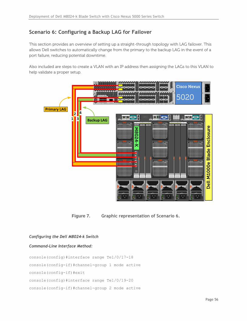
Scenario 6: Configuring a Backup LAG for Failover
This section provides an overview of setting up a straight-through topology with LAG failover. This
allows Dell switches to automatically change from the primary to the backup LAG in the event of a
port failure, reducing potential downtime.
Also included are steps to create a VLAN with an IP address then assigning the LAGs to this VLAN to
help validate a proper setup.
`STAT
CONSOLE
L1
L2
MGMT 0
MGMT 14 8 12 16
3 7 11 15
2 6 10 14
1 5 9 13
20 24 28 32
19 23 27 31
18 22 26 30
17 21 25 29
SLO
T2
34 38
33 37
36 40
35 39
SLO
T3
Cisco Nexus 5020
PS
1P
S2
200-240v-6A50~60Hz
De
ll M
10
00
e B
lad
e E
nc
losu
re
B2C2 A2B1 C1A1
4
1
7
5
2
8
6
3
9
CMC2CMC1 KVM
1 2 3 4 5 6
GbGb 21
CMC
iKVM
GbGb 21
CMC
12
34
CONSOLE
Po
we
rC
on
ne
ct M
80
24
-k
17
18
19
20
M8
02
4-K
12
3
4
Cisco Nexus
5020
Backup LAG
Primary LAG
Figure 7. Graphic representation of Scenario 6.
Configuring the Dell M8024-k Switch
Command-Line Interface Method:
console(config)#interface range Te1/0/17-18
console(config-if)#channel-group 1 mode active
console(config-if)#exit
console(config)#interface range Te1/0/19-20
console(config-if)#channel-group 2 mode active
Deployment of Dell M8024-k Blade Switch with Cisco Nexus 5000 Series Switch
Page 57
console(config-if)#exit
console(config)#vlan database
console(config-vlan)#vlan 100
console(config-vlan)#exit
console(config)#interface port-channel 1
console(config-if-Po1)#switchport mode general
console(config-if-Po1)#switchport general allowed vlan add 100 tagged
console(config-if-Po1)#exit
console(config)#interface port-channel 2
console(config-if-Po2)#switchport mode general
console(config-if-Po2)#switchport general allowed vlan add 100 tagged
console(config-if-Po2)#exit
console(config)#interface vlan 100
console(config-if-vlan100)#ip address 1.1.1.10 255.255.255.0
console(config-if-vlan100)#exit
console(config)#link–dependency group 1
console(config-linkDep-group-1)#add port-channel 2
console(config-linkDep-group-1)#depends-on port-channel 1
console(config-linkDep-group-1)#action up
console(config-linkDep-group-1)#end
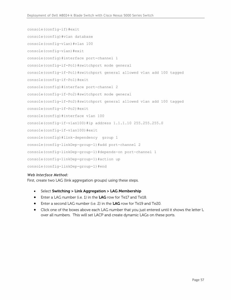
Web Interface Method:
First, create two LAG (link aggregation groups) using these steps.
Select Switching > Link Aggregation > LAG Membership
Enter a LAG number (i.e. 1) in the LAG row for Te17 and Te18.
Enter a second LAG number (i.e. 2) in the LAG row for Te19 and Te20.
Click one of the boxes above each LAG number that you just entered until it shows the letter L
over all numbers. This will set LACP and create dynamic LAGs on these ports.
Deployment of Dell M8024-k Blade Switch with Cisco Nexus 5000 Series Switch
Page 58
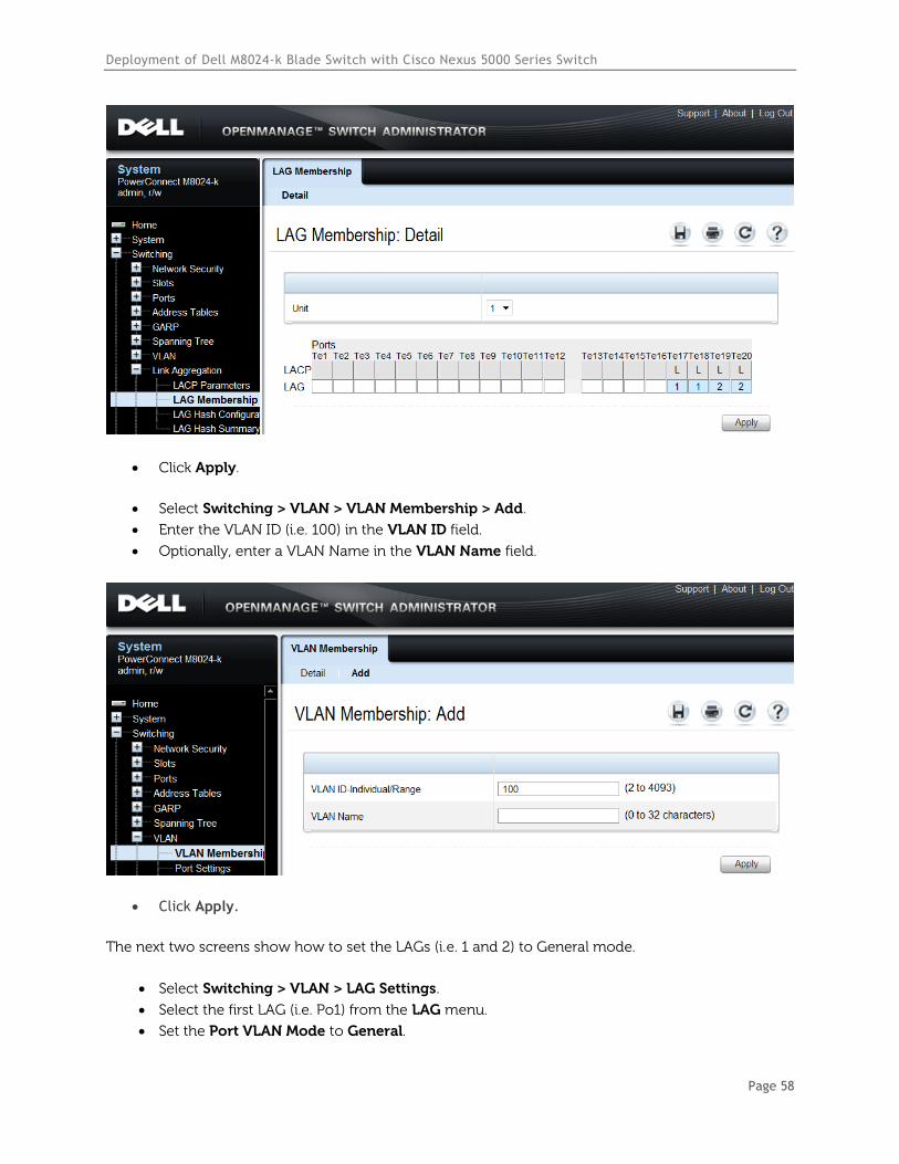
Click Apply.
Select Switching > VLAN > VLAN Membership > Add.
Enter the VLAN ID (i.e. 100) in the VLAN ID field.
Optionally, enter a VLAN Name in the VLAN Name field.
Click Apply.
The next two screens show how to set the LAGs (i.e. 1 and 2) to General mode.
Select Switching > VLAN > LAG Settings.
Select the first LAG (i.e. Po1) from the LAG menu.
Set the Port VLAN Mode to General.
Deployment of Dell M8024-k Blade Switch with Cisco Nexus 5000 Series Switch
Page 59
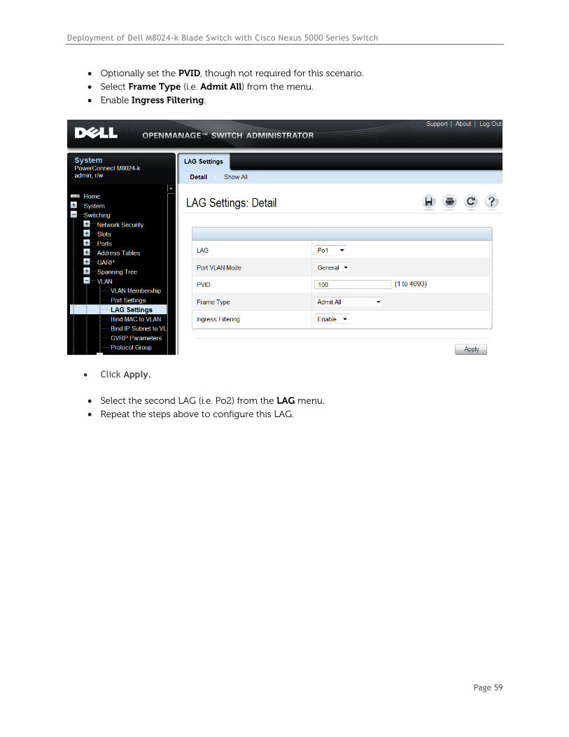
Optionally set the PVID, though not required for this scenario.
Select Frame Type (i.e. Admit All) from the menu.
Enable Ingress Filtering.
Click Apply.
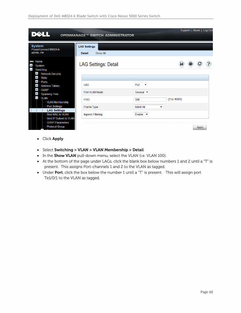
Select the second LAG (i.e. Po2) from the LAG menu.
Repeat the steps above to configure this LAG.
Deployment of Dell M8024-k Blade Switch with Cisco Nexus 5000 Series Switch
Page 60
Click Apply.
Select Switching > VLAN > VLAN Membership > Detail.
In the Show VLAN pull-down menu, select the VLAN (i.e. VLAN 100).
At the bottom of the page under LAGs, click the blank box below numbers 1 and 2 until a “T” is
present. This assigns Port-channels 1 and 2 to the VLAN as tagged.
Under Port, click the box below the number 1 until a “T” is present. This will assign port
Te1/0/1 to the VLAN as tagged.
Deployment of Dell M8024-k Blade Switch with Cisco Nexus 5000 Series Switch
Page 61
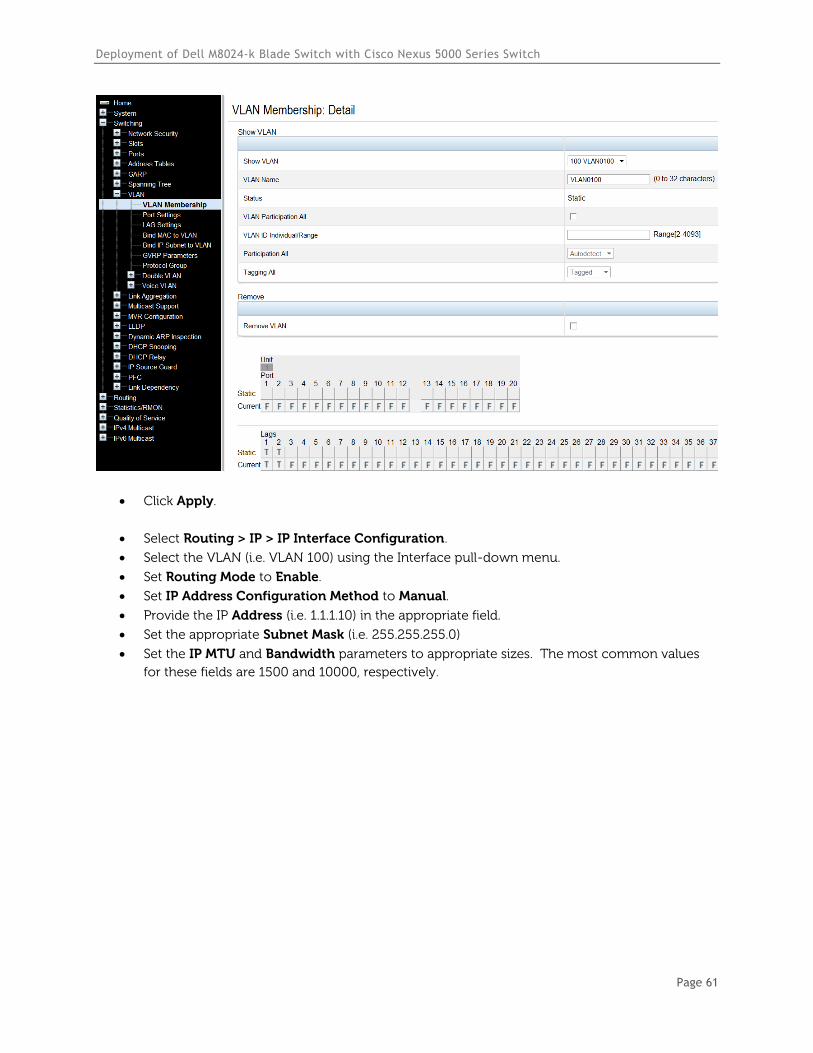
Click Apply.
Select Routing > IP > IP Interface Configuration.
Select the VLAN (i.e. VLAN 100) using the Interface pull-down menu.
Set Routing Mode to Enable.
Set IP Address Configuration Method to Manual.
Provide the IP Address (i.e. 1.1.1.10) in the appropriate field.
Set the appropriate Subnet Mask (i.e. 255.255.255.0)
Set the IP MTU and Bandwidth parameters to appropriate sizes. The most common values
for these fields are 1500 and 10000, respectively.
Deployment of Dell M8024-k Blade Switch with Cisco Nexus 5000 Series Switch
Page 62
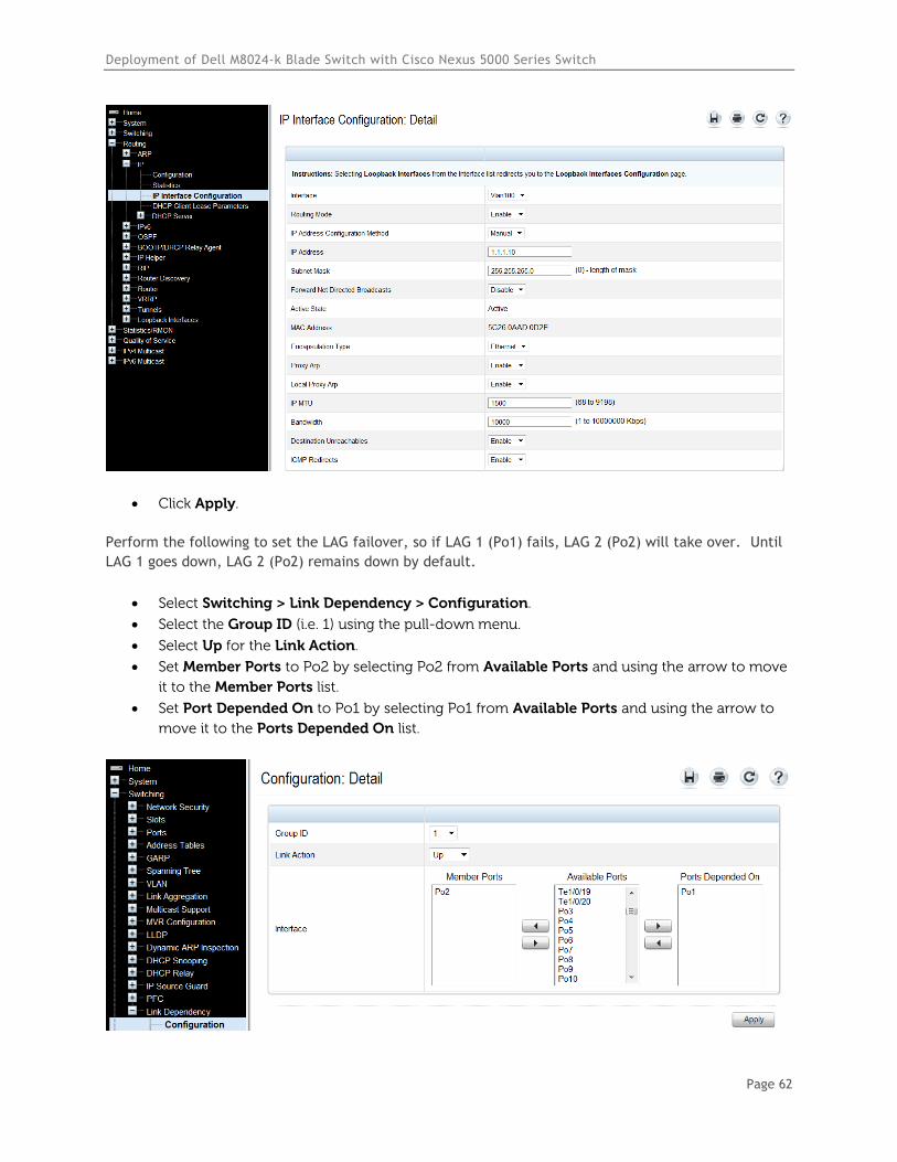
Click Apply.
Perform the following to set the LAG failover, so if LAG 1 (Po1) fails, LAG 2 (Po2) will take over. Until
LAG 1 goes down, LAG 2 (Po2) remains down by default.
Select Switching > Link Dependency > Configuration.
Select the Group ID (i.e. 1) using the pull-down menu.
Select Up for the Link Action.
Set Member Ports to Po2 by selecting Po2 from Available Ports and using the arrow to move
it to the Member Ports list.
Set Port Depended On to Po1 by selecting Po1 from Available Ports and using the arrow to
move it to the Ports Depended On list.
Deployment of Dell M8024-k Blade Switch with Cisco Nexus 5000 Series Switch
Page 63
Click Apply.
Configuring the Cisco Nexus 5020 Switch
Login to the Nexus 5020 and make the following changes:
Nexus5020# configure
Enter configuration commands, one per line. End with CNTL/Z.
Nexus5020(config)# feature lacp
Nexus5020(config)# interface ethernet 1/1-4
Nexus5020(config if-range)#switchport
Nexus5020(config-if-range)# channel-group 1 mode active
Nexus5020(config-if-range)# no shutdown
Nexus5020(config-if-range)# exit
Nexus5020(config)# feature interface-vlan
Nexus5020(config)# interface vlan 100
Nexus5020(config-if)# ip address 1.1.1.20/24
Nexus5020(config-if)# no shutdown
Nexus5020(config-if)# exit
Nexus5020(config)# vlan 100
Nexus5020(config-vlan)# state active
Nexus5020(config-vlan)# exit
Nexus5020(config)# interface port-channel 1
Nexus5020(config-if)# switchport mode trunk
Nexus5020(config-if)# switchport trunk allowed vlan 100
Nexus5020(config-if)# end
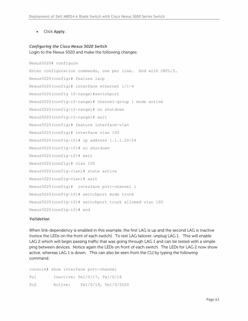
Validation
When link-dependency is enabled in this example, the first LAG is up and the second LAG is inactive
(notice the LEDs on the front of each switch). To test LAG failover, unplug LAG 1. This will enable
LAG 2 which will begin passing traffic that was going through LAG 1 and can be tested with a simple
ping between devices. Notice again the LEDs on front of each switch. The LEDs for LAG 2 now show
active, whereas LAG 1 is down. This can also be seen from the CLI by typing the following
command:
console# show interface port-channel
Po1 Inactive: Te1/0/17, Te1/0/18
Po2 Active: Te1/0/19, Te1/0/2020
Deployment of Dell M8024-k Blade Switch with Cisco Nexus 5000 Series Switch
Page 64
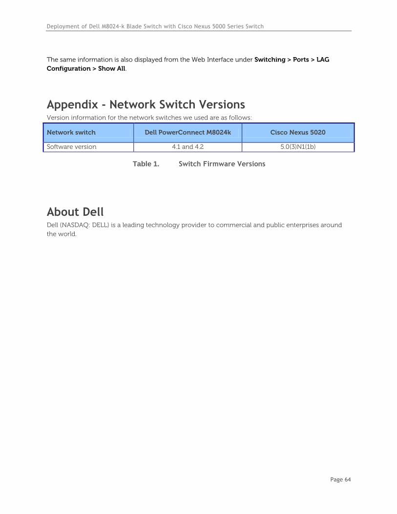
The same information is also displayed from the Web Interface under Switching > Ports > LAG
Configuration > Show All.
Appendix - Network Switch Versions Version information for the network switches we used are as follows:
Network switch Dell PowerConnect M8024k Cisco Nexus 5020
Software version 4.1 and 4.2 5.0(3)N1(1b)
Table 1. Switch Firmware Versions
About Dell Dell (NASDAQ: DELL) is a leading technology provider to commercial and public enterprises around
the world.