Embed Size (px)
Citation preview
1
Pertino HA Cluster Deployment: Enabling a Multi-‐Tier Web Application Using Amazon EC2 and Google CE A Pertino Deployment Guide

2
Table of Contents Abstract ....................................................................................................................................... 2
Introduction .............................................................................................................................. 3 Before you get Started ........................................................................................................... 4
Architecture .............................................................................................................................. 4 Implementing Multi-‐tier Web Application in HA Deployment: ............................... 5 Installing the Pertino VPN Client for Linux .............................................................................. 5 Installation on Ubuntu .................................................................................................................................. 5 Installation on Redhat and CentOS .......................................................................................................... 6
Seting Up MongoDB with Data Replication ............................................................................... 8 Setting Up MongoDB Replica Set .............................................................................................................. 8 Setting Up MongoDB Arbiter ...................................................................................................................... 9
Setting Up Load Balancers ........................................................................................................... 10 Setting Up Elastic Load Balancer ........................................................................................................... 11 Configuring listeners for Amazon Load Balancers ..................................................................................... 11 Configuring health check for your Amazon EC2 instances .................................................................... 12 Registering your Amazon EC2 instances ........................................................................................................ 13 Reviewing your settings ......................................................................................................................................... 14 Verifying your settings ............................................................................................................................................ 14 Testing your Load Balancer .................................................................................................................................. 15
Setting up HA Proxy ..................................................................................................................................... 15 Installing HAProxy on Ubuntu ............................................................................................................................. 15 Configuring HAProxy ............................................................................................................................................... 16 Starting the HA Proxy service .............................................................................................................................. 18
Amazon Route 53 ........................................................................................................................... 18 Creating a Hosted Zone .............................................................................................................................. 19 Creating a hosted zone using the Amazon Route 53 console ................................................................. 19
Active/Passive Failover using Route53 Failover ................................................................. 21 Working with Resource Record Sets ................................................................................................................ 21 Creating Resource Record Sets for ELB ........................................................................................................... 22 Create Resource Record Sets for HAProxy ..................................................................................................... 23 Validating Route 53 setup for load balancing ............................................................................................... 24
Conclusion ........................................................................................................................................ 25
Abstract This guide illustrates the process of configuring HA services for Pertino cloud deployments across Amazon EC2 and Google Compute Engine. It is intended for DevOps professionals who are familiar with Linux CLI, networking concepts, and cloud services. By following the procedures in this guide, you can set up a resilient, highly available web application leveraging two providers so that your network remains up and running day and night, year-‐round.
3
Introduction Today, almost all web applications architectures are designed with built-‐in High Availability (and Failover) capabilities. HA web applications can be deployed in single or multiple regions of a single cloud provider with failover, or they can be deployed across multiple cloud providers. There are several benefits to setup a HA Web Application across multiple cloud providers:
• IT departments that are not satisfied with the stability and robustness of their existing public cloud providers may want multi-‐cloud provider deployments to ensure uptime and resiliency.
• Opting for multi-‐cloud providers can prevent lock-‐in with a single cloud provider and companies can easily move resources.
• Large enterprises that already have invested heavily on their existing data centers/providers and/or have private clouds set up may want a public cloud like AWS to be their HA/DR cloud partner.
One of the challenges commonly faced in single cloud multi-‐region, or multi-‐cloud deployments is the ability to securely replicate data in databases. A common solution is to set up a secure VPN tunnel between servers -‐-‐ but a VPN deployment is complex, requires specialized skillsets to maintain, and is not cost effective. Pertino is a cloud VPN solution that removes all the complexity involved in setting up VPNs. Pertino lets engineers build cloud networks to connect, secure, and manage cloud resources anywhere—in minutes and without hardware. You simply sign up, download the Pertino client on to the virtual machine, and get started. The Pertino Cloud Network Engine is powered by a cloud network OS platform that uses next generation networking technologies like overlay network virtualization and software-‐defined networking (SDN). The software platform is hosted in top-‐tier data centers around the world and leverages their massive computing power and redundant multi-‐gigabit connections to the Internet backbone to ensure optimal network scale and performance. With the Pertino Cloud Network Engine, IT professionals can create fully switched, cloud-‐based virtual networks that combine the easy accessibility of the Internet with the end-‐to-‐end security and control of a private network. This guide targets IT infrastructure administrators and DevOps personnel. After reading this step-‐by-‐step guide, you should have a good understanding of how to deploy a multi-‐tier web application across multiple cloud providers and leverage the Pertino Cloud VPN solution for establishing secure encrypted tunnels across these clouds.

4
Before you get Started Implementing the multi-‐cloud deployment scenario with Pertino VPN requires understanding and knowledge of the following concepts:
• Creating Virtual Machines in Amazon EC2 • Creating Virtual Machines in Google Compute Engine • Using SSH • Installing and configuring Apache, PHP, and MongoDB
It is also assumed that you have a Pertino account and network created.
Architecture In this guide we set up a multi-‐tier application (PHP Application with MongoDB backend) across two cloud providers – Amazon EC2 and Google Compute Engine with high availability (and failover). The MongoDB backend will be implemented with data replication in order to ensure high availability of data and a robust failover system. We'll configure an application stack with the following components:
• Secure DNS routing -‐ Amazon Route53 • Load Balancer -‐ Elastic Load Balancer (in Amazon EC2) and HA-‐Proxy (in Google Compute
Engine) • Web Servers -‐ Apache/PHP • Database Servers – MongoDB in replication mode • Pertino Cloud VPN

5
Figure 1. Reference architecture for HA deployment across multiple clouds.
Implementing Multi-‐tier Web Application in HA Deployment: In this section, we guide users through the actual implementation. The first step involves creating all the Linux servers in the both clouds and installing the Pertino VPN client on each server. Once the Pertino client is set up, each virtual machine will get a private FQDN and be displayed in the management console.
Installing the Pertino VPN Client for Linux Pertino Linux Client is available for both Ubuntu and CentOS flavors of Linux. On each of the servers created (across both clouds), set up the Pertino agents as follows:
Installation on Ubuntu 1. Install the Pertino GPG signing key.
wget -‐O -‐ http://reposerver.pertino.com/Pertino-‐GPG-‐Key.pub | sudo apt-‐key add -‐
2. Add the Pertino repository server to the distribution sources list.

6
sudo sh -‐c "echo 'deb http://reposerver.pertino.com/debs precise multiverse' > /etc/apt/sources.list.d/pertino.list"
3. Install the Pertino client. sudo apt-‐get update && sudo apt-‐get -‐y install pertino-‐client
4. You will be prompted for your Pertino user information. Enter your username and password.
Installation on Redhat and CentOS 1. Download the latest Pertino package for your platform and install.
sudo wget -‐O /etc/yum.repos.d/pertino.repo http://reposerver.pertino.com /pertino.repo
2. Install the Pertino client. sudo yum -‐y install pertino-‐client
3. To start Pertino, you must enter your Pertino account credentials by running the .pauth command. Then start the Pertino service. sudo –I cd /opt/pertino/pgateway ./.pauth -‐u <username> -‐p <password>
You now have a new network interface attached to your private Pertino network. To confirm, display the Pertino virtual interface with ifconfig or view the Pertino management interface.
ifconfig pertino0
The pertino0 interface will have a dynamic private address for IPv4 and IPv6. You will also have a privately accessible FQDN displayed in the management console. ! NOTE: all the configurations for the connections between various software entities will be using the Pertino client and hence private FQDNs will be used in configuration files. In the above example we have the following servers and associated private FQDNs in the following table:
7
Cloud Server Type Private FQDN Amazon EC2
Web Server ip-‐10-‐168-‐60-‐2.8ptvk5.pertino.net
ip-‐10-‐173-‐26-‐119.8ptvk5.pertino.net
MongoDB Server
(secondary and arbiter)
ip-‐10-‐182-‐237-‐88.8ptvk5.pertino.net
ip-‐10-‐225-‐178-‐73.8ptvk5.pertino.net
Google Compute Engine
HA Proxy ha-‐proxy.8ptvk5.pertino.net
Web Server web-‐server-‐1.8ptvk5.pertino.net
web-‐server-‐2.8ptvk5.pertino.net
MongoDB Server (primary) mongodb.8ptvk5.pertino.net
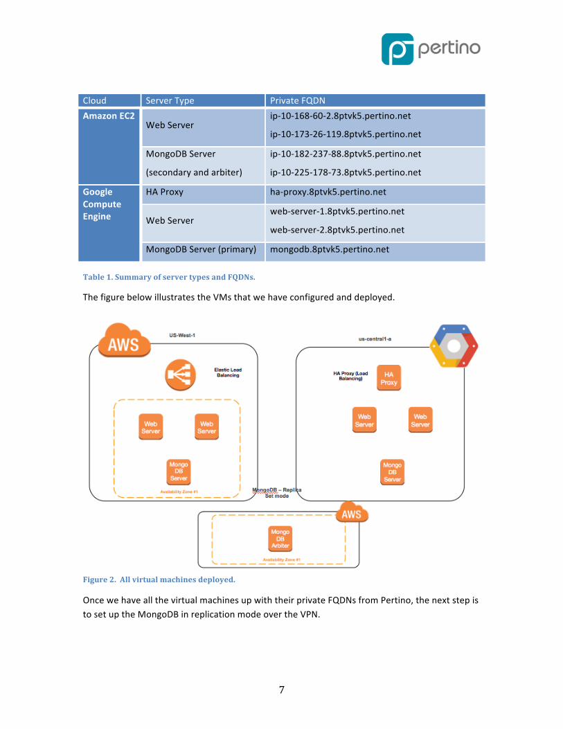
Table 1. Summary of server types and FQDNs.
The figure below illustrates the VMs that we have configured and deployed.
Figure 2. All virtual machines deployed.
Once we have all the virtual machines up with their private FQDNs from Pertino, the next step is to set up the MongoDB in replication mode over the VPN.

8
Seting Up MongoDB with Data Replication MongoDB handles data replication through an implementation called Replication Sets. Replication Sets are somewhat similar to nodes in a master-‐slave configuration where a single primary member is used as the base for applying changes to secondary members. The difference between a Replication Set and master-‐slave replication is that a Replication Set has an intrinsic automatic failover mechanism in case the primary member becomes unavailable. The following terms may be helpful: Primary member: The primary member is the default access point for transactions with the Replication Set. It is the only member that can accept write operations. Each Replication Set can have only one primary member at a time. Secondary members: A Replication Set can contain multiple secondary members. A secondary member can become the primary if the primary goes offline or steps down. Arbiter: An arbiter is an optional member of a Replication Set that does not take part in the actual replication process. It is added to the Replication Set to participate in only a single, limited function: to act as a tiebreaker in elections. In the event that the primary member becomes unavailable, an automated election process happens among the secondary nodes to choose a new primary. If the secondary member pool contains an even number of nodes, this could result in an inability to elect a new primary due to a voting impasse. The arbiter votes in these situations to ensure a decision is reached.
Setting Up MongoDB Replica Set At this stage, the guide assumes that MongoDB server has been installed on the servers and the mongod service is up and running. The guide now describes the steps setup the Replica Set.
1. Login in to the MongoDB server – you plan to assign as the master. (In this case it's mongodb.8ptvk5.pertino.net.)
2. Open mongo shell and connect to the mongod service, simply by issuing: mongo
3. Initiate the replica set.
rs.initiate()
4. MongoDB initiates a set that consists of the current member and that uses the default replica set configuration.

9
5. Verify the initial replica set configuration. Use rs.conf() to display the replica set configuration object:
rs.conf()
6. The Replica Set configuration object resembles the following:
{ "_id" : "rs0", "version" : 1, "members" : [ { "_id" : 1, "host" : " mongodb.8ptvk5.pertino.net:27017" } ] }
7. Check the status of the replica set. Use the rs.status() operation:
rs.status()
8. Add the remaining members to the Replica Set with the rs.add() method. The following example adds the other member: rs.add("ip-‐10-‐182-‐237-‐88.8ptvk5.pertino.net")
Setting Up MongoDB Arbiter The following procedure illustrates setting up the MongDB arbiter.
1. Connect to the primary and add the arbiter to the Replica Set. Use the rs.addArb() method, as in the following example: rs.addArb(“ip-‐10-‐225-‐178-‐73.8ptvk5.pertino.net”)
When complete, you have a fully functional Replica Set. The new Replica Set will elect a primary. You can deploy the web application of your choice that will communicate with the MongoDB Replica Set. For the sake of the guide, we assume a simple PHP application hosted on Apache. The PHP-‐based application will be deployed on all the web servers (described in Figure 1).

10
You need to ensure that the application communicates with the MongoDB Replication Set over the private FQDN assigned by the Pertino client even though the servers may be in the same cloud. This ensures that the application in one cloud can communicate with the MongoDB server in the other cloud in case the primary server goes down and the secondary server is elected as the master. At this stage, your application should be accessible from each web server and should be able to communicate with the Mongo Replication Set successfully.
Figure 3. MongoDB configured in Replication Set and Pertino VPN.
Setting Up Load Balancers The next step is setting up the load balancers for each cloud. The Load Balancer automatically distributes incoming web traffic across multiple servers connected to it. If one server fails, the Load Balancer reroutes the traffic to the remaining running servers. If the failed server is restored, the Load Balancer restores traffic to that server. Amazon Web Services (AWS) provides Elastic Load Balancing (ELB) to automatically distribute incoming web traffic across multiple Amazon Elastic Compute Cloud (Amazon EC2) instances, which we will use for our EC2 Web Servers. Elastic Load Balancing offers clients a single point of contact and can also serve as the first line of defense against attacks on your network. You can also offload the work of encryption and decryption to Elastic Load Balancing, so your servers can focus on their main task.

11
For Google's Compute Engine, we will use HAProxy, an open source load balancer. HAProxy can be run on Linux, Solaris, and FreeBSD.
Setting Up Elastic Load Balancer The following instructions will help you create a basic load balancer using the AWS Management Console, a point-‐and-‐click web-‐based interface.
Configuring listeners for Amazon Load Balancers 1. Sign in to the AWS Management Console and open the Amazon EC2 console at
https://console.aws.amazon.com/ec2/.
2. Start the Create Load Balancer wizard: a. On the Amazon EC2 console Resources page, in the EC2 Dashboard pane, under
NETWORK & SECURITY, click Load Balancers. b. On the Load Balancers page, click Create Load Balancer
Figure 4. Amazon EC2 Resources pane.
3. On the Define Load Balancer page, make the following selections: a. In the Load Balancer name: field, enter a name for your load balancer (for
example, pertino-‐balancer). The load balancer name you choose must be unique within your set of load balancers, must have a maximum of 32 characters, and must only contain alphanumeric characters or hyphens.
b. Leave Create LB inside: field set to "EC2-‐Classic" for this guide. c. Leave Listener Configuration: fields set to the default values for this example.
The default settings require that your Amazon EC2 HTTP servers are active and accepting requests on port 80.

12
Figure 5. Amazon Define Load Balancer pane.
4. Click Continue to configure health check for your Amazon EC2 instances. Elastic Load Balancing routinely checks the health of each load-‐balanced Amazon EC2 instance based on the configurations that you specify. If Elastic Load Balancing finds an unhealthy instance, it stops sending traffic to that instance and reroutes traffic to healthy instances.
Configuring health check for your Amazon EC2 instances 1. On the Configure Health Check page of the Create Load Balancer wizard, set the
following configurations: a. Leave Ping Protocol set to its default value of HTTP. b. Leave Ping Port set to its default value of 80. Elastic Load Balancing pings the
port you choose (in this example, port 80) to send health check queries to your Amazon EC2 instances. Your Amazon EC2 instances must accept incoming traffic on the ping port. This example assumes that each of your instances has a working webserver that accepts incoming traffic on port 80.
c. In the Ping Path field, replace the default value with a single forward slash ("/"). Elastic Load Balancing sends health check queries to the path you specify in the Ping Path field. This example uses a single forward slash so that Elastic Load Balancing sends the query to your webserver's default home page, whether that default page is named "index.html", "default.html", or a different name.
2. Click Continue to register your Amazon EC2 instances with your load balancer.

13
Figure 6. Amazon Configure Health Check pane.
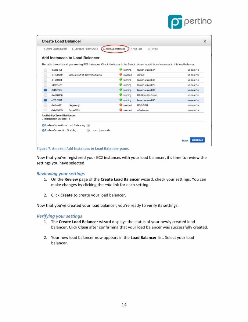
Registering your Amazon EC2 instances 1. On the Add EC2 Instances page, in the Add Instances to Load Balancer table, select the
boxes in the Instance column to register instances with your load balancer.
2. Keep Enable Cross-‐Zone Load Balancing and Enable Connection Draining boxes set to the default settings for this guide. Click Continue.
3. For this guide, skip the step for adding tags and click Continue to review your settings and then create your load balancer.
14
Figure 7. Amazon Add Instances to Load Balancer pane.
Now that you've registered your EC2 instances with your load balancer, it's time to review the settings you have selected.
Reviewing your settings 1. On the Review page of the Create Load Balancer wizard, check your settings. You can
make changes by clicking the edit link for each setting.
2. Click Create to create your load balancer.
Now that you've created your load balancer, you're ready to verify its settings.
Verifying your settings 1. The Create Load Balancer wizard displays the status of your newly created load
balancer. Click Close after confirming that your load balancer was successfully created.
2. Your new load balancer now appears in the Load Balancer list. Select your load balancer.
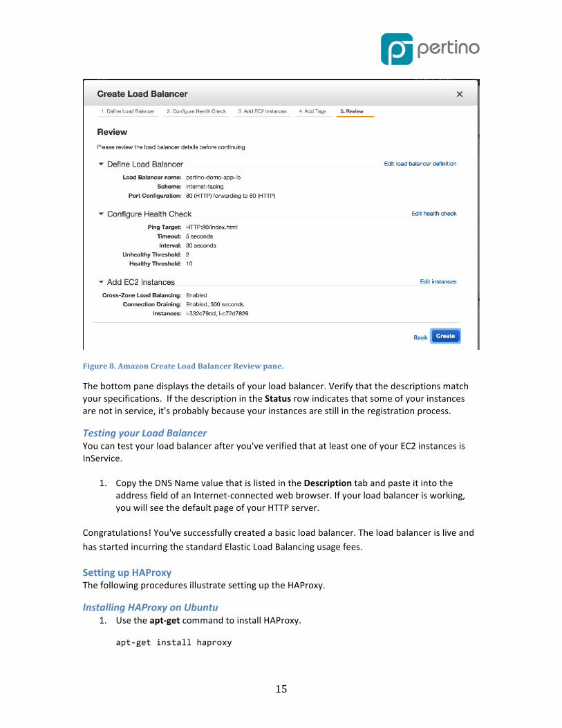
15
Figure 8. Amazon Create Load Balancer Review pane.
The bottom pane displays the details of your load balancer. Verify that the descriptions match your specifications. If the description in the Status row indicates that some of your instances are not in service, it's probably because your instances are still in the registration process.
Testing your Load Balancer You can test your load balancer after you've verified that at least one of your EC2 instances is InService.
1. Copy the DNS Name value that is listed in the Description tab and paste it into the address field of an Internet-‐connected web browser. If your load balancer is working, you will see the default page of your HTTP server.
Congratulations! You've successfully created a basic load balancer. The load balancer is live and has started incurring the standard Elastic Load Balancing usage fees.
Setting up HAProxy The following procedures illustrate setting up the HAProxy.
Installing HAProxy on Ubuntu 1. Use the apt-‐get command to install HAProxy.
apt-‐get install haproxy

16
2. We need to enable HAProxy to be started by the init script. nano /etc/default/haproxy
3. Set the ENABLED option to 1
ENABLED=1
4. To check if this change is done properly, execute the init script of HAProxy without any parameters. You should see the following. root@haproxy:~# service haproxy Usage: /etc/init.d/haproxy {start|stop|reload|restart|status}
Configuring HAProxy 1. We'll move the default configuration file and create our own one.
mv /etc/haproxy/haproxy.cfg{,.original}
2. Create and edit a new configuration file:
nano /etc/haproxy/haproxy.cfg
3. Let's begin by adding configuration block by block to this file: global log 127.0.0.1 local0 notice maxconn 2000 user haproxy group haproxy Directives log: specifies a syslog server to which log messages will be sent. maxconn: specifies the number of concurrent connections on the frontend. The default value is 2000 and should be tuned according to your SERVER's configuration. user and group: changes the HAProxy process to the specified user/group. These should not be changed.
4. Additional default configuration block text should be added in the following format:
defaults log global mode http option httplog option dontlognull retries 3 timeout connect 5000 timeout client 10000
17
timeout server 10000 Directives We're specifying default values in this section. The values to be modified are the various timeout directives. connect: specifies the maximum time to wait for a connection attempt to a server to succeed. client and server timeouts apply when the client or server is expected to acknowledge or send data during the TCP process. HAProxy recommends setting the client and server timeouts to the same value. retries: sets the number of retries to perform on a server after a connection failure.
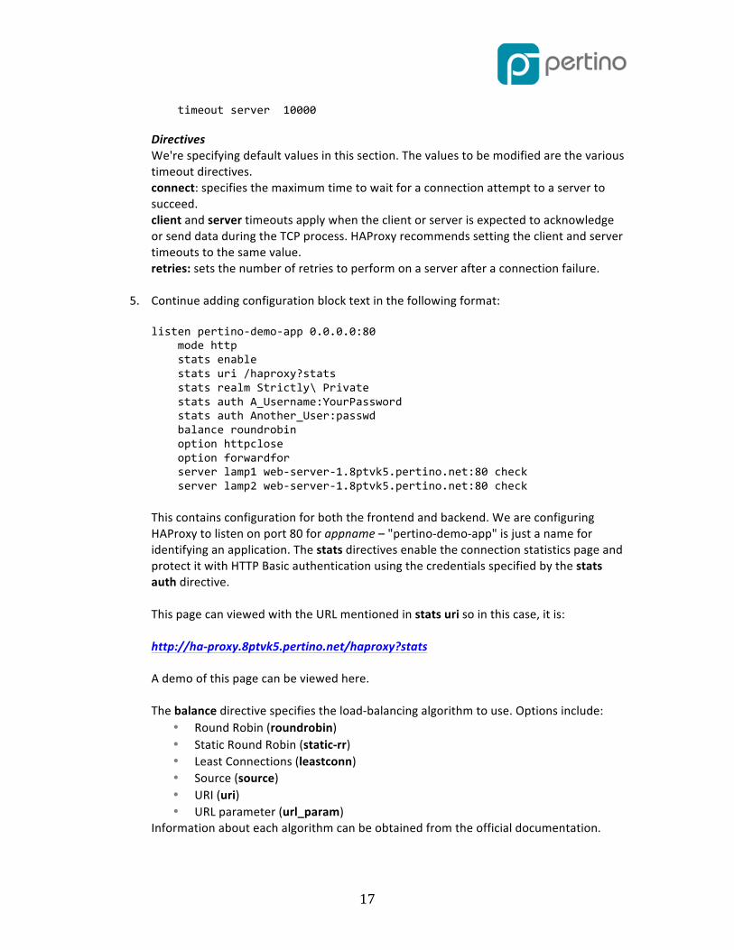
5. Continue adding configuration block text in the following format: listen pertino-‐demo-‐app 0.0.0.0:80 mode http stats enable stats uri /haproxy?stats stats realm Strictly\ Private stats auth A_Username:YourPassword stats auth Another_User:passwd balance roundrobin option httpclose option forwardfor server lamp1 web-‐server-‐1.8ptvk5.pertino.net:80 check server lamp2 web-‐server-‐1.8ptvk5.pertino.net:80 check This contains configuration for both the frontend and backend. We are configuring HAProxy to listen on port 80 for appname – "pertino-‐demo-‐app" is just a name for identifying an application. The stats directives enable the connection statistics page and protect it with HTTP Basic authentication using the credentials specified by the stats auth directive. This page can viewed with the URL mentioned in stats uri so in this case, it is: http://ha-‐proxy.8ptvk5.pertino.net/haproxy?stats A demo of this page can be viewed here. The balance directive specifies the load-‐balancing algorithm to use. Options include:
• Round Robin (roundrobin) • Static Round Robin (static-‐rr) • Least Connections (leastconn) • Source (source) • URI (uri) • URL parameter (url_param)
Information about each algorithm can be obtained from the official documentation.

18
The server directive declares a backend server. The syntax is: server <name> <address>[:port] [param*] The name we specify here will appear in logs and alerts.
Starting the HAProxy service
1. Now that you've completed configuration, start the HAProxy service: service haproxy start
At this stage, we have both the load balancers configured in the clouds. Ensure the following:
• The Application is accessible via Elastic Load Balancers’ Public FQDN • The Application is accessible via the HAProxy public IP address • Validate that the same data is visible on both the instances of the application to validate
that MongoDB Replication is also working.
Figure 9. Load Balancer set up -‐-‐ ELB and HA Proxy.
The next step is setting up Amazon Route53. Route53 is a DNS service that provides reliable routing to your infrastructure.
Amazon Route 53 Amazon Route 53 lets you configure DNS failover in active-‐active, active-‐passive, and mixed configurations to improve the availability of your application. We have two deployments performing the same function, i.e. running a web application — we can configure Amazon Route

19
53 to check the health of our resources and respond to DNS queries using only the healthy resources. We can also configure Amazon Route 53 to check the health of those servers and to respond to DNS queries using only the servers that are currently healthy. Amazon Route 53 is a scalable Domain Name System (DNS) web service. It provides secure and reliable routing to your infrastructure that uses Amazon Web Services (AWS) products, such as Amazon Elastic Compute Cloud (Amazon EC2), Elastic Load Balancing, or Amazon Simple Storage Service (Amazon S3). You can also use Amazon Route 53 to route users to your infrastructure outside of AWS. In this guide, we will be using the active-‐passive configuration for our high availability setup. Here's how Amazon Route 53 responds to requests in this configuration:
• If Amazon Route53 considers the primary resource (ELB) healthy (if the healthcheck endpoint is healthy), Amazon Route 53 returns only the primary resource in response to a DNS query.
• If Amazon Route53 considers the primary resource (ELB) unhealthy and the secondary resource (HA Proxy) healthy, Amazon Route 53 returns the secondary resource instead.
In this guide, we will assume that you already have an existing Domain (e.g., pertino-‐demo.net) and the domain will be migrated from an existing service to Amazon Route 53.
Creating a Hosted Zone To migrate a domain from your existing DNS service, start by creating an Amazon Route 53 hosted zone. Amazon Route 53 stores information about your domain in the hosted zone.
Creating a hosted zone using the Amazon Route 53 console 1. Sign in to the AWS Management Console and open the Amazon Route 53 console at
https://console.aws.amazon.com/route53/.
2. If necessary, click Hosted Zones in the Navigation pane.
3. Click Create Hosted Zone.

20
Figure 10. The Hosted Zone panel.
4. In the Create Hosted Zone pane, enter a domain name and, optionally, a comment. For more information about a setting, pause the mouse pointer over its label to see a tool tip.
Figure 11. The Create Hosted Zone pane.

21
5. Click Create.
When you create a hosted zone, Amazon Route 53 automatically creates four name server (NS) records and a start of authority (SOA) record for the zone. The NS records identify the name servers that you give to your registrar or your DNS service so that queries are routed to Amazon Route 53 name servers.
Figure 12. The Hosted Zone Details pane.
Active/Passive Failover using Route53 Failover The following sections configuring Route 53.
Working with Resource Record Sets After you create a hosted zone for your domain, such as "pertino-‐demo.com", you create resource record sets to tell the DNS how you want traffic to be routed for that domain. In our guide, we want the traffic routed to two load balancers – ELB in Amazon EC2 and HAProxy in Google Compute Engine. You can create an active-‐passive failover configuration by using failover resource record sets. You create a primary and a secondary failover resource record set, where each has the same name and type, and you associate a health check with each.

22
In this guide, the primary resource is ELB and the secondary failover resource is HAProxy. The primary and secondary failover resource record sets can refer to anything from an Amazon S3 bucket that is configured as a website, to a complex tree of resource record sets. When all of the resources that are referenced by the primary failover resource record set are unhealthy, Amazon Route 53 automatically begins responding to queries by using the resources that are referenced by the secondary failover resource record set.
Creating Resource Record Sets for ELB Ordinary Amazon Route 53 resource record sets are standard DNS resource record sets: alias re-‐ source record sets provide an Amazon Route 53–specific extension to DNS functionality. Instead of an IP address or a domain name, an alias resource record set contains a pointer to a CloudFront distribution, an ELB load balancer, an Amazon S3 bucket that is configured as a static website, or another Amazon Route 53 resource record set in the same hosted zone. When Amazon Route 53 receives a DNS query that matches the name and type in an alias resource record set, Amazon Route 53 follows the pointer and responds with the applicable value. In case of an ELB load balancer, Amazon Route 53 responds to each request with one or more IP addresses for the load balancer. The steps to add the ELB Is as follows:
1. On the Hosted Zones page, double-‐click the row for the hosted zone in which you want to create alias resource record sets.
2. Click Create Record Set.
3. Enter the applicable values. a. Select the Alias and enter the DNS name of the Load Balancer. (In the
navigation pane, click Load Balancers. In the list of load balancers, select the load balancer for which you want to create an alias resource record set. On the Description tab, get the DNS name that is labeled A or AAAA Record).
b. Select the Routing Policy as Failover (for active-‐passive failover as described previously).
c. Select Evaluate Target Health. d. Select Create.
See Figure 13, below.

23
Figure 13. Amazon Route 53 Create Record Set panel for ELB.
Create Resource Record Sets for HAProxy The HAProxy is a standard server with the public IP address. The steps to add the HAProxy are as follows:
1. On the Hosted Zones page, double-‐click the row for the hosted zone in which you want to create resource record sets.
2. Click Create Record Set. 3. Enter the applicable values.
a. Alias – Mark as "No" since this is a standard resource set b. Value -‐ Enter the Public IP address of the HA Proxy server c. Routing Policy – Set to "Failover" d. Failover Record Type – Set to "Secondary" e. Skip the health check
See Figure 14, below.
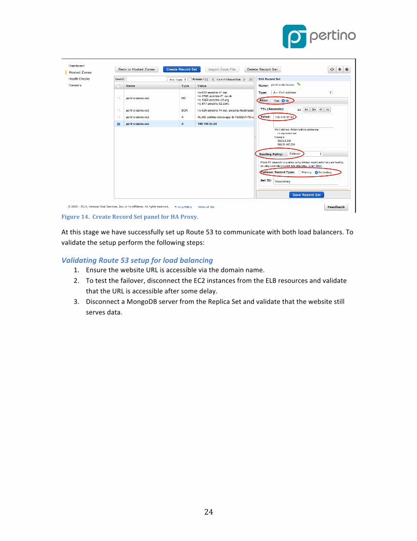
24
Figure 14. Create Record Set panel for HA Proxy.
At this stage we have successfully set up Route 53 to communicate with both load balancers. To validate the setup perform the following steps:
Validating Route 53 setup for load balancing 1. Ensure the website URL is accessible via the domain name. 2. To test the failover, disconnect the EC2 instances from the ELB resources and validate
that the URL is accessible after some delay. 3. Disconnect a MongoDB server from the Replica Set and validate that the website still
serves data.

25
Figure 15. Final setup architectural diagram.
Conclusion In this guide, we walked through the steps necessary to set up a High Available Web portal across multiple clouds using Pertino VPN for secure encrypted communication. Pertino VPN provides an easy and convenient way to setup VPN connections across virtual machines in different geographies. This guide enables you to set up an HA/DR configuration across multiple clouds/datacenters in a easy, predictable, and manageable way. Although the guide covered only a certain application stack, the same guide can be useful for setting up multi-‐tier applications with other components, including:
• SQL Servers as Database servers • Java-‐based Application servers • Other services like Messaging and Caching. • Alternative solutions to HAProxy for Load Balancing.
Additionally, we recommend you consult the AWS documentation and customize some of the steps described in this guide or add additional ones to deploy a solution that best meets your high availability (HA) and disaster recovery (DR) application availability requirements.