Embed Size (px)
Citation preview

Hitachi Content PlatformDeploying an HCP-VM System
MK-92ARC040-02

© 2013-2015 Hitachi Data Systems Corporation. All rights reserved.
No part of this publication may be reproduced or transmitted in any form or by any means, electronic ormechanical, including photocopying and recording, or stored in a database or retrieval system for anypurpose without the express written permission of Hitachi Data Systems Corporation (hereinafter referredto as “Hitachi Data Systems”).
Hitachi Data Systems reserves the right to make changes to this document at any time without notice andassumes no responsibility for its use. This document contains the most current information available at thetime of publication. When new and/or revised information becomes available, this entire document will beupdated and distributed to all registered users.
Some of the features described in this document may not be currently available. Refer to the most recentproduct announcement or contact your local Hitachi Data Systems sales office for information aboutfeature and product availability.
Notice: Hitachi Data Systems products and services can be ordered only under the terms and conditions ofthe applicable Hitachi Data Systems agreement. The use of Hitachi Data Systems products is governed bythe terms of your agreement with Hitachi Data Systems.
By using this software, you agree that you are responsible for:
a) Acquiring the relevant consents as may be required under local privacy laws or otherwise fromemployees and other individuals to access relevant data; and
b) Ensuring that data continues to be held, retrieved, deleted, or otherwise processed in accordance withrelevant laws.
Hitachi is a registered trademark of Hitachi, Ltd., in the United States and other countries. Hitachi DataSystems is a registered trademark and service mark of Hitachi in the United States and other countries.
Archivas, Essential NAS Platform, HiCommand, Hi-Track, ShadowImage, Tagmaserve, Tagmasoft,Tagmasolve, Tagmastore, TrueCopy, Universal Star Network, and Universal Storage Platform areregistered trademarks of Hitachi Data Systems Corporation.
AIX, AS/400, DB2, Domino, DS6000, DS8000, Enterprise Storage Server, ESCON, FICON, FlashCopy, IBM,Lotus, MVS, OS/390, RS6000, S/390, System z9, System z10, Tivoli, VM/ESA, z/OS, z9, z10, zSeries,z/VM, and z/VSE are registered trademarks or trademarks of International Business Machines Corporation.
Hi-Track is a registered trademark of Hitachi Data Systems.
Dell is a registered trademark and PowerConnect is a trademark of Dell Inc.
Linux is a registered trademark of Linus Torvalds in the United States, other countries, or both.
Mac OS is a registered trademark of Apple Inc, registered in the U.S. and other countries.
MegaRAID is a registered trademark of LSI Corporation.
Microsoft, Active Directory, Excel, Internet Explorer, andWindows are registered trademarks of MicrosoftCorporation in the United States and/or other countries.
Mozilla and Firefox are registered trademarks of The Mozilla Foundation.
UNIX is a registered trademark of The Open Group.
All other trademarks, service marks, and company names are properties of their respective owners.
Microsoft product screen shots reprinted with permission from Microsoft Corporation.

Notice Export Controls. The technical data and technology inherent in this Document may be subject toU.S. export control laws, including the U.S. Export Administration Act and its associated regulations, andmay be subject to export or import regulations in other countries. Reader agrees to comply strictly with allsuch regulations and acknowledges that it has the responsibility to obtain licenses to export, re-export, orimport the Document and any Compliant Products.

Contents
Preface viiiIntended audience viiiProduct version viiiRelated documents viiiGetting help xiComments xi
Chapter 1: HCP system overview 1Introduction to Hitachi Content Platform 1HCP-VM system components and architecture 1
Host platform 2Compute 2Storage 2HCP network connectivity 4Front-end network 5Storage network 5Back-end network 5Hardware monitoring and alerting 6HCP software 6HCP upgrades 7HCP search nodes 7HCP-VM node failover (vCenter and vSphere HA) 7Storage licensing 8
Chapter 2: Configuration guidelines for HCP-VM environment 9VMware supported versions 9VMware supported functionality 9Prerequisites and recommendations 10
Contents iv
Deploying an HCP-VM System

HCP-VM system limits 12
Chapter 3: Configuring the HCP-VM environment 15ESXi considerations 15Enabling NTP for the ESXi hosts 15Configure vSphere HA cluster for HCP-VM (Recommended) 18Provisioning HCP-VM storage 33Add datastores to vSphere HA cluster 38NFS Datastores 48Creating an NFS datastore 49Heartbeat datastore selection 50Preparing the ESXi network for the HCP-VM OVF deployment 51
Configuring the Storage Network (HNAS Best Practice) 52Configuring networking for Front-end switching 53Configure networking for Back-end switching 59Verifying ESXi configuration on all hosts 61
Chapter 4: Creating the HCP-VM system 69Unpacking the OVF Zip file 69Deploying the HCP-VM OVF VDMK 69Deploy the HCP-VM OVF RDM 81Configuring HCP-VM network 97Install HCP software 102
Identify the nodes in the HCP system 103Configure the HCP system 107Execute the installation 114Verifying the HCP installation 118
Setting additional configuration options 120Monitoring and alerting 121
Monitoring and alerts 121Software monitoring 121HCP resource monitoring 122HCP diagnostic menu 123
Chapter 5: Failover management 124Maintenance procedures 125
Adding logical volumes 125Adding HCP-VM nodes 133
v Contents
Deploying an HCP-VM System

Appendix A: Configuring networking for HCP virtual networkmanagement 135
HCP networking information 135OVF deployment information 139
Appendix B: Changing the VMDK target size 141
Appendix C: DRS settings 143Setting an alarm 155
Glossary 159
Index 171
Contents vi
Deploying an HCP-VM System

vii Contents
Deploying an HCP-VM System

Preface
This book is the setup guide for Hitachi Content Platform (HCP) VMsystems. It provides the information you need to deploy a virtualized HCPsystem in your VMware vSphere® environment. In order to complete theinstallation there are instances where you may want to reference othermaterials.
Intended audience
This book is intended for the people responsible for deploying an HCP-VMsystem at a customer site. It assumes you have experience with computernetworking, creating virtual machines, familiarity with VMware productsand concepts, and a basic understanding of HCP systems.
Product version
This book applies to release 7.1 of HCP.
Related documents
The following documents contain additional information about HitachiContent Platform:
• Administering HCP - This book explains how to use an HCP system tomonitor and manage a digital object repository. It discusses thecapabilities of the system, as well as its hardware and softwarecomponents. The book presents both the concepts and instructions youneed to configure the system, including creating the tenants thatadminister access to the repository. It also covers the processes thatmaintain the integrity and security of the repository contents.
viii
Deploying an HCP-VM System

• Managing a Tenant and Its Namespaces - This book contains completeinformation for managing the HCP tenants and namespaces created inan HCP system. It provides instructions for creating namespaces,setting up user accounts, configuring the protocols that allow access tonamespaces, managing search and indexing, and downloadinginstallation files for HCP Data Migrator. It also explains how to work withretention classes and the privileged delete functionality.
• Managing the Default Tenant and Namespace - This book containscomplete information for managing the default tenant and namespacein an HCP system. It provides instructions for changing tenant andnamespace settings, configuring the protocols that allow access to thenamespace, managing search and indexing, and downloadinginstallation files for HCP Data Migrator. It also explains how to work withretention classes and the privileged delete functionality.
• Replicating Tenants and Namespaces - This book covers all aspects oftenant and namespace replication. Replication is the process of keepingselected tenants and namespaces in two or more HCP systems in syncwith each other to ensure data availability and enable disaster recovery.The book describes how replication works, contains instructions forworking with replication links, and explains how to manage and monitorthe replication process.
• HCP Management API Reference - This book contains the informationyou need to use the HCP management API. This RESTful HTTP APIenables you to create and manage tenants and namespacesprogrammatically. The book explains how to use the API to access anHCP system, specify resources, and update and retrieve resourceproperties.
• Using a Namespace - This book describes the properties of objects inHCP namespaces. It provides instructions for accessing namespaces byusing the HTTP, WebDAV, CIFS, and NFS protocols for the purpose ofstoring, retrieving, and deleting objects, as well as changing objectmetadata such as retention and shred settings. It also explains how tomanage namespace content and view namespace information in theNamespace Browser.
• Using the HCP HS3 API - This book contains the information you needto use the HCP HS3 API. This S3™-compatible, RESTful, HTTP-basedAPI enables you to work with buckets and objects in HCP. The bookintroduces the HCP concepts you need to understand in order to use
Related documents
ix
Deploying an HCP-VM System

HS3 effectively and contains instructions and examples for each of thebucket and object operations you can perform with HS3.
• Using the HCP OpenStack Swift API - This book contains theinformation you need to use the HCP OpenStack Swift API. This S3™-compatible, RESTful, HTTP-based API enables you to work withcontainers and objects in HCP. The book introduces the HCP conceptsyou need to understand in order to use HSwift effectively and containsinstructions and examples for each of the container and objectoperations you can perform with HSwift.
• Using the Default Namespace - This book describes the file systemHCP uses to present the contents of the default namespace. It providesinstructions for accessing the namespace by using the HCP-supportedprotocols for the purpose of storing, retrieving, and deleting objects, aswell as changing object metadata such as retention and shred settings.
• HCP Metadata Query API Reference - This book describes the HCPmetadata query API. This RESTful HTTP API enables you to querynamespaces for objects that satisfy criteria you specify. The bookexplains how to construct and perform queries and describes queryresults. It also contains several examples, which you can use as modelsfor your own queries.
• Searching Namespaces - This book describes the HCP Search Console(also called the Metadata Query Engine Console). It explains how to usethe Console to search namespaces for objects that satisfy criteria youspecify. It also explains how to manage and manipulate queries andsearch results. The book contains many examples, which you can use asmodels for your own searches.
• Using HCP Data Migrator - This book contains the information you needto install and use HCP Data Migrator (HCP-DM), a utility that works withHCP. This utility enables you to copy or move data between local filesystems, namespaces in HCP, and earlier HCAP archives. It alsosupports bulk delete operations and bulk operations to change objectmetadata. Additionally, it supports associating custom metadata andACLs with individual objects. The book describes both the interactivewindow-based interface and the set of command-line tools included inHCP-DM.
• Installing an HCP System - This book provides the information youneed to install the software for a new HCP system. It explains what you
Related documents
x
Deploying an HCP-VM System

need to know to successfully configure the system and contains step-by-step instructions for the installation procedure.
• Third-Party Licenses and Copyrights - This book contains copyrightand license information for third-party software distributed with orembedded in HCP.
• HCP-DM Third-Party Licenses and Copyrights - This book containscopyright and license information for third-party software distributedwith or embedded in HCP Data Migrator.
• Installing an HCP SAIN System - Final On-site Setup - This bookcontains instructions for deploying an assembled and configured single-rack HCP SAIN system at a customer site. It explains how to make thenecessary physical connections and reconfigure the system for thecustomer computing environment. It also contains instructions forconfiguring Hi-Track® Monitor to monitor the nodes in an HCP system.
• Installing an HCP RAIN System - Final On-site Setup - This bookcontains instructions for deploying an assembled and configured HCPRAIN system at a customer site. It explains how to make the necessaryphysical connections and reconfigure the system for the customercomputing environment. The book also provides instructions forassembling the components of an HCP RAIN system that was orderedwithout a rack and for configuring Hi-Track Monitor to monitor the nodesin an HCP system.
Getting help
The Hitachi Data Systems customer support staff is available 24 hours aday, seven days a week. If you need technical support, call:
• United States: (800) 446-0744
• Outside the United States: (858) 547-4526
Note: If you purchased HCP from a third party, please contact yourauthorized service provider.
Comments
Please send us your comments on this document:
Getting help
xi
Deploying an HCP-VM System

Include the document title, number, and revision, and refer to specificsections and paragraphs whenever possible. All comments become theproperty of Hitachi Data Systems.
Thank you!
Comments
xii
Deploying an HCP-VM System

xiii
Deploying an HCP-VM System

HCP system overview
This chapter introduces HCP, and describes the architecture for an HCPsystem installed in a VMware vSphere environment.
Introduction to Hitachi Content Platform
Hitachi Content Platform (HCP) is a distributed storage systemdesigned to support large, growing repositories of fixed-content data. AnHCP system consists of both hardware (physical or virtual) and software.
HCP stores objects as both data and metadata.Metadata is responsible fordescribing the object. HCP distributes these objects across the storagespace, and represents them as either URLs or files in a standard file system.
An HCP repository is partitioned into namespaces. Each namespaceconsists of a distinct logical grouping of objects with its own directorystructure. Namespaces are owned and managed by tenants.
HCP provides access to objects through a variety of industry-standardprotocols, as well as through various HCP-specific interfaces.
HCP-VM system components and architecture
This section describes the components and architecture of an HitachiContent Platform Virtual Machine (HCP-VM) system.
Chapter 1: HCP system overview 1
Deploying an HCP-VM System
1

The illustration below shows the architecture of an HCP-VM system.
Host platform
In an HCP-VM system, each node runs in a virtual machine on an ESXi host.Depending on the capabilities of the underlying hardware, more than oneHCP-VM node can run on a single ESXi host.
Compute
Each HCP-VM node will have at least eight vCPUs and at least 32 GB of RAMallocated. This will enable the system to maintain performance for mostclient workloads and HCP system activities like encryption, scheduledservice runs and routine database maintenance.
Storage
HCP-VM relies on the storage infrastructure to provide highly available andfault tolerant storage. It is recommended that the physical servers the ESXihosts run on be connected to shared SAN storage with RAID6 protection orHitachi NAS (HNAS).
2 Chapter 1: HCP system overview
Deploying an HCP-VM System
HCP-VM system components and architecture

SAN storage must provide at least two paths to each Logical Unit Number(LUN) and each of those LUNs must be presented to each ESXi host withthe exact same LUN number (HLUN).
A datastore will be created from each LUN or export, creating one VirtualMachine File System (VMFS) volume per LUN or export. A single datastorewill not be shared by HCP-VM nodes. However, HCP-VM nodes can havemultiple datastores. Each datastore will be carved into one or multipleVirtual Machine Disks (VMDK) which are presented to the HCP OS as localdisks. The HCP OS will recognize its storage as internal drives similar toHCP300 RAIN nodes. The disks will be controlled by the VMware ParavirtualSCSI controller (PVSCSI). VMware recommends PVSCSI for better overallperformance.
Tip: The PVSCSI adapter reduces CPU utilization and potentially increasesthroughput compared to default virtual storage adapters
Each VMDK can be a maximum size of 2TB minus 512bytes.
In addition to the recommended RAID6, shared SAN storage configuration,and HNAS datastores, HCP-VM also supports the following for storageconfiguration:
• Shared SAN arrays with virtual volumes created from Hitachi DynamicProvisioning (DP) pools. This configuration does not support thinprovisioning. The recommended best practice is to spread datastoresacross multiple DP Pools so as to avoid resource contention and singlepoints of failure as much as possible.
• Shared SAN arrays with LUNs configured using Raw Device Mapping(RDM) in vSphere® Client or vCenter™. The RDM is to be configured inPhysical Mode.
• Other devices like HNAS that export NFS v3 shares, which are mountedand used as VMFS datastores.
– It is required to use thick, eager zero when formatting NFSdatastores, so additional ESXi plug-ins may be required from yourvendor. Hitachi provides a VAAI plug-in that enables thisfunctionality on the HNAS platform.
Chapter 1: HCP system overview 3
Deploying an HCP-VM System
HCP-VM system components and architecture

– It is recommended to not have multiple datastores on the same filesystem or the same underlying disk due to performance andavailability considerations.
– Follow the vendors best practice for configuring NFS datastores.
• RAID-protected storage that’s internal to the ESXi hosts. Each LUNcreated from this storage corresponds to a VMFS datastore. Thisconfiguration does not support vSphere High Availability (HA). Theunderlying storage in this configuration must be RAID protected.
When varying from the recommended configuration, careful considerationneeds to be taken when planning the storage for an HCP-VM system. Manyfactors such as: performance, availability, backup, security, ease ofmanagement and data integrity. Ensure that you completely understandfailure scenarios, HDD failure rates, RAID protection levels, RAID rebuildtimes, support windows, etc. Health of the systems must be monitoredclosely with any failures serviced immediately so as to ensure underlyingstorage does not fail.
For information on supported storage vendors and devices, see theapplicable VMware documentation.
Always follow the vendor’s best practices for configuring their storage in aVMware environment.
HCP network connectivity
HCP-VM network connectivity are provided to the HCP guest OS by VMwaree1000 vNICs, VMware vSwitches, and dvSwitches. It is recommended thatthe vNICs connect to a single vSwitch for Back-end connectivity and a singlevSwitch for Front-end connectivity. The Back-end vSwitch must beconfigured to provide access to two vmNICs and the Front-end vSwitchmust be configured to provide access to a different set of two vmNICs. ThevmNICs are setup for NIC teaming for failover by default.
Tip: NIC Teams are multiple physical network adapters sharing a singevSwitch and the physical network. NIC teams provide passive failover ifthere is a hardware failure or network outage. In some configurations theycan increase performance by distributing the traffic across physical networkadapters.
4 Chapter 1: HCP system overview
Deploying an HCP-VM System
HCP-VM system components and architecture

Front-end network
HCP’s Front-end network is used for management of the system and clientaccess. For HCP’s Front-end network, it is recommended that the ESXi hostwill present two vNICs on a second pair of pNICs. Best practice is to havethose pNICs dedicated to HCP for greater redundancy and more consistentperformance.
When two NICs are not available for the Front-end network, it is possible tooperate HCP-VM with one NIC provided it has enough available bandwidthto support data traffic and management access. It should be noted that inthe event of a failure of that single NIC, the HCP-VM node(s) that reside onthat ESXi host will not be available to clients, but will still be available to theHCP-VM system through the Back-end network.
Storage network
HDS recommends that the VMkernal network be set up in a private networkor with a unique VLAN ID that provides network isolation.
Back-end network
HCP’s private Back-end network is used for inter-node communication anddata transfer between nodes.
Due to the inter-node communication, it is mandatory that the back-endnetwork is configured to allow multi-cast communication between all nodesin the HCP-VM system. In most cases, it is not enough to just have multi-cast enabled on the switch. There will most likely be additional configurationparameters necessary to allow for the multi-cast traffic. Follow the switchvendor documentation to configure the network to allow multi-cast trafficbetween the HCP-VM nodes. It should be noted that it is possible to deployan HCP-VM system via the system installation program, and not have multi-cast configured correctly. The processes that require multi-castcommunication are not active until after installation. When multi-cast is notconfigured correctly, the HCP-VM system will attempt to boot to itsoperational runlevel, only to fall back to a lower runlevel once multi-castcommunication fails.
For HCP’s Back-end network, it is recommended that the ESXi host presenttwo vmNICs which directly map to two physical NICs (pNICs) on the ESXihost server. It is recommended the pNICs be connected to two physicalswitches, on an isolated network, where pNIC-1 on all ESXi hosts connect to
Chapter 1: HCP system overview 5
Deploying an HCP-VM System
HCP-VM system components and architecture

the same physical switch (switch1) and pNIC-2 on all ESXi hosts connect tothe same physical switch (switch2). When using two physical switches,there must be an inter-switch connection that allows connectivity for allHCP-VM network ports on one switch to all HCP-VM network ports on thesecond switch. The pNICs and the switches to which they are connectedshould be isolated from all other networks in the customer environment. The switches must not be configured with spanning tree disabled, allowmulti-cast traffic, be at least 1GbE and should be dedicated to HCP toguarantee data security and HCP reliability.
In the event that the HCP-VM back-end network travels over a publicnetwork, it is strongly recommended that the HCP-VM system reside on itsown VLAN.
When two NICs are not available for the Back-end network, it is possible tooperate HCP-VM with one NIC provided that it has enough availablebandwidth to support data traffic and inter-node communication. It shouldbe noted that in the event of a failure of that single NIC, the HCP-VM node(s) that reside on that ESXi host will not be available to the HCP-VM system.
Hardware monitoring and alerting
The HCP hardware based appliance has built in redundant hardware,monitoring, alerting and failover behavior that cannot be leveraged in avirtualized VMware environment. To maintain performance and dataintegrity, it is recommended that all underlying hardware associated withthe HCP-VM system be treated as mission critical and monitored forfailures. Whenever Hitachi servers, storage and networking are part of theHCP-VM system, it is recommended they be connected to HiTrack. Any non-Hitachi equipment should be closely monitored using the vendor orcustomer equivalent to HiTrack. Any failures in the HCP-VM infrastructuremust be corrected as soon as possible. Drive failures, in particular, shouldbe closely monitored given the possibility of lengthy RAID rebuild times.
HCP software
HCP-VM provides all the same (non-hardware specific) functionality as HCPRAIN and SAIN systems. Data is RAID protected, and HCP policies andservices ensure its integrity and security and optimize its space used ondisk. The management and data access interfaces are the same as for RAINand SAIN systems. A small amount of features are not available in an HCP-VM system because they are physical hardware based, so they are notpractical or feasible in a virtualized environment.
6 Chapter 1: HCP system overview
Deploying an HCP-VM System
HCP-VM system components and architecture

HCP upgrades
HCP v5.0 introduced HCP Evaluation edition for proof of concept (POC) andtest activities at HDS partner and customer sites. Upgrades from theEvaluation Edition single node and Evaluation Edition multi-node to HCP-VM are not supported. HCP-VM supports upgrades from the initial 6.0release to future releases of HCP-VM.
HCP search nodes
HCP search has reached end of service life, therefore HCP search nodes arenot available for HCP-VM systems. As with physical HCP systems, thisfunctionality is provided by the Hitachi HDDS Enterprise search product.
HCP-VM node failover (vCenter and vSphere HA)
If you wish to set up automatic failover in the event of an ESXi host failure,HCP-VM requires an instance of the VMware vCenter server to be availablein the customer environment for enabling HCP-VM node failover. Failoverfunctionality is provided by a vSphere HA cluster.
A vSphere High Availability (HA) cluster lets a collection of ESXi hosts worktogether to optimize their levels of availability. You are responsible forconfiguring the cluster to respond to host and virtual machine failures.
Each ESXi host participating in an HCP-VM system will be configured to bepart of a single vSphere HA cluster in vCenter. This enables high availabilityin cases where one or more servers or ESXi hosts fail. When the master hostdetects a server or ESXi host failure, it can restart the HCP-VM nodes thatwere running on the server or ESXi host that failed on other healthy ESXihosts in the cluster.
The master host monitors the status of slave hosts in the cluster. This isdone through network heartbeat exchanges every second. If the masterhost stops receiving heartbeats from a slave, it checks for liveness beforedeclaring a failure. The liveness check is to determine if the slave isexchanging heartbeats with a datastore.
The HCP-VM vSphere HA cluster will not be configured to automaticallymove the failed-over HCP-VM node back to its original ESXi host once theserver or ESXi host is available. The HCP-VM system administrator willmanually shutdown the HCP-VM node, and the vCenter administrator will
Chapter 1: HCP system overview 7
Deploying an HCP-VM System
HCP-VM system components and architecture

manually move the HCP-VM node onto the preferred ESXi host and poweron the HCP-VM node. Once the node boots, it will re-join the HCP-VMsystem.
In the case of network isolation, the HCP-VM vSphere HA cluster will beconfigured to leave the HCP-VM node powered on. In this case, the HCP-VMnode will still be able to communicate over its private Back-end networkwith the other HCP-VM nodes in the system. Just like in the case of aphysical HCP node, the HCP-VM node and the data it is managing willremain available to the system through the Front-end of the other nodes inthe HCP-VM system.
The vCenter server used to configure the vSphere HA cluster of ESXi hostsfor the HCP-VM system can either be a pre-existing server in the customerenvironment, or can be allocated as part of the HCP-VM HA cluster of ESXihosts. It is recommended (but not required) that the vCenter server beseparate from the HCP-VM HA cluster. The vCenter server can consume afair amount of resources on the ESXi host which could be utilized by theHCP-VM nodes.
The rules for creating a vSphere HA cluster for use with HCP-VM are veryspecific. If the HCP-VM system is to be added to an existing HA cluster,ensure that the cluster is configured exactly to the specifications in thisguide.
Storage licensing
HCP-VMs come with a storage license that provides two terabytes of activestorage and a two terabytes of extended storage. If you need more storagespace, please contact your HDS sales representative to purchase morestorage license capacity.
If you upgrade HCP to version 7.1, you receive an unlimited storage licensethat applies to both active and extended storage for one year.
For more information about storage licensing, see Administering HCP.
8 Chapter 1: HCP system overview
Deploying an HCP-VM System
HCP-VM system components and architecture

Configuration guidelines for HCP-VMenvironment
This chapter describes the requirements and recommendations forsuccessful installation and operation of an HCP-VM system.
VMware supported versions
HCP-VM supports the following versions of VMware:
• VMware vCenter server 5.5
• VMware ESXi 5.0 update 2, 5.1 update 2, and 5.5
• VMFS - 5
• Virtual Machine Version: 8
VMware supported functionality
HCP-VM supports the following VMware functionality:
• vSphere HA cluster
• The VMware tools package included in the HCP OS with HCP-VM 7.0.1.This lets the HCP-VM node shutdown from the vCenter managementconsole. Pausing live migration, and other functionality enabled by theinclusion of the tools package are not currently supported.
• DRS may be used in a manual capacity to assist with VM to host affinityas described in Appendix D.
Chapter 2: Configuration guidelines for HCP-VM environment 9
Deploying an HCP-VM System
2

• Other failover capabilities provided by VMware such as vMotion, storagevMotion, DRS and FT are not supported by this version of HCP-VM.
The following HCP features are specific to the physical HCP appliances(HCP300/HCP500/HCP500XL) and are not applicable to HCP-VM throughalternate means:
• Autonomic Tech Refresh: Provides the capability of migrating a VM toa different host, this allows for server refresh. The raw storage layer isobscured from HCP in the VMware environment; any storage refreshwould need to be handled at the VMware layer.
• Zero Copy Failover: VMware HA replaces this capability by restartingan HCP guest VM on a running ESXi host after it is lost due to an ESXihost failure. This ZCF-like storage availability is provided by shared SANstorage.
• Specialized HCP LUNs
– Spindown, IDX (indexing) only: Spindown is not compatible withthe VMware environment. Indexing only LUNs are not available inHCP-VM with this release. Shared index LUNs are standard as with allother HCP systems.
• HCP integrated HDvM monitoring: The raw storage layer is obscuredfrom HCP in the VMware environment, storage connected to HCP-VMneeds to be monitored at the customer site via their preferredmechanism.
• VLAN tagging: VMware's active-active NIC Teaming is designed forload balancing and redundancy. Both physical NIC's must be configuredwith the same VLAN tagging. Also, VMware vSwitch is a layer 3 switchand will not route traffic out physical NICs per VLAN tagging. You cannotconfigure physical vmNIC2 to be tagged on VLAN 20 and physicalvmNIC3 to be tagged on VLAN 30 so that VMware will route HCP trafficout the appropriate physical NIC.
Prerequisites and recommendations
The following list is a composition of the prerequisite and recommendedhardware for deploying an HCP-VM system:
• Minimum of 4 HCP-VM nodes in an HCP-VM system
• Minimum 8 vCPU allocated per HCP-VM node (allocated in OVF)
10 Chapter 2: Configuration guidelines for HCP-VM environment
Deploying an HCP-VM System
Prerequisites and recommendations

• Minimum 32GB RAM allocated per HCP-VM node (allocated in OVF)
– In addition to the recommended configuration of 32GB of physicalRAM per HCP-VM virtual machine on each ESXi host (for example,128GB of physical RAM for four virtual machines), HCP-VM supportsovercommitting RAM. Be aware, however, that overcommitting RAMcan degrade the performance of the HCP-VM system.
– For best practices relating to overcommitting RAM, see theapplicable VMware documentation.
• Maximum 256GB RAM allocated per HCP-VM node (allocated in OVF)
• Shared SAN storage, RAID6 (Recommended)
• Minimum four 1.2TB LUNs allocated for default VMDK size deployment
Chapter 2: Configuration guidelines for HCP-VM environment 11
Deploying an HCP-VM System
Prerequisites and recommendations

• NFS datastores: Recommended Volume Size
– As discussed in VMware NFS Best Practice: “The followingstatementappears in the VMware Configuration Maximums Guide: “Contactyour storage array vendor or NFS server vendor for information aboutthe maximum NFS volume size.” When creating this paper, we askeda number of our storage partners if there was a volume size thatworked well. All partners said that there was no performance gain ordegradation depending on the volume size and that customers mightbuild NFS volumes of any size, so long as it was below the arrayvendor’s supported maximum. This can be up in the hundreds ofterabytes, but the consensus is that the majority of NFS datastoresare in the tens of terabytes in terms of size. The datastores sizes varygreatly from customer to customer.”
• Datastores cannot be shared across HCP-VM nodes or other non-HCP-VMapplications
• Two physical NICs on each ESXi host in the vSphere HA cluster dedicated for HCP-VM Back-end network (Recommended)
• Two physical NICs available for the VMware management network forvSphere HA (Recommended)
– HCP-VM Front-end will also utilize these NICs
• Two port fibre channel HBA (or VMware compatible IO device) for sharedstorage connectivity (when applicable)
• ESXi requires a minimum of 2GB of physical RAM. VMware recommendsproviding at least 8GB of RAM to take full advantage of ESXi featuresand run virtual machines in typical production environments.
HCP-VM system limits
The HCP-VM system is limited to the following requirements:
• 40 HCP-VM nodes
• 59 data LUNs per HCP-VM node (ESXi guest OS limitation)
• Two 500GB VMDKs minimum per HCP-VM node
• 3.66TB minimum usable per HCP-VM system
12 Chapter 2: Configuration guidelines for HCP-VM environment
Deploying an HCP-VM System
HCP-VM system limits
• Max open VMDK storage per host (ESXi Limitation)
– 5.0 update 2: 60TB
– 5.1 update 2: 60TB
– 5.5: 3.63TB
• 2TB VMDK (5.1 and 5.2 VMFS-5 limitation. 5.5 supports 64TB VMDK,but not supported by HCP-VM)
• HCP supported limits can be found in both the customer and authorizedHCP release notes.
Chapter 2: Configuration guidelines for HCP-VM environment 13
Deploying an HCP-VM System
HCP-VM system limits

14 Chapter 2: Configuration guidelines for HCP-VM environment
Deploying an HCP-VM System

Configuring the HCP-VM environment
This section will cover the steps required to provision the VMwareenvironment to be ready for an HCP-VM deployment. These steps includethe following:
• ESXi considerations
• Configuring vSphere HA cluster
• Configuring ESXi storage
• Configuring ESXi network
ESXi considerations
A customer may want to deploy the HCP-VM system on existing ESXi hostsin their environment. Before attempting to do this, make sure the hostsmeet the minimum requirements for compute and memory cataloged in"Chapter 2: Configuration guidelines for HCP-VM environment" onpage 9.
All ESXi hosts that will contain HCP-VM nodes must have Network TimeProtocol (NTP) enabled. This is done from the vSphere client by clicking onTime Configuration under Software on the Configuration tab on eachindividual ESXi host.
Important: NTP must be enabled for each ESXi host individually.
Enabling NTP for the ESXi hosts
To configure ESXi hosts for NTP:
Chapter 3: Configuring the HCP-VM environment 15
Deploying an HCP-VM System
3

1. Access your vSphere client.
2. In the left side navigation window, select the ESXi host for which youwant to enable NTP.
3. In the right hand window, click on the Configuration tab.
4. Under the Software section in the right hand window, click TimeConfiguration.
5. In the upper right hand corner of the right hand window, click onProperties.
6. In the In the Time Configuration window, select the NTP ClientEnabledcheck box.
7. Click on Options.
16 Chapter 3: Configuring the HCP-VM environment
Deploying an HCP-VM System
Enabling NTP for the ESXi hosts

8. In the NTP Daemon Options window, select Start and stop with host.
9. In the left side navigation bar, click on NTP Settings.
10. In the NTP Serverssection of the NTP Daemon Options window, click Addand enter the time server.
11.Select the Restart NTP service to apply changes checkbox.
12.Click OK and OK again in the Time Configuration window.
13.Repeat the procedure with the same time server for all ESXi hosts thatwill have HCP-VM nodes.
Tip: Write down the NTP server used in your ESXi hosts so you can use itfor the HCP-VM installation.
Chapter 3: Configuring the HCP-VM environment 17
Deploying an HCP-VM System
Enabling NTP for the ESXi hosts

Configure vSphere HA cluster for HCP-VM(Recommended)
A vSphere HA cluster lets a collection of ESXi hosts work together tooptimize their levels of availability. You are responsible for configuring thecluster to respond to host and virtual machine failures.
Step 1: Creating a data center
To create a datacenter:
1. Access the vSphere Client.
2. In the vSphere client, under the Getting Started tab, click on Create adatacenter.
18 Chapter 3: Configuring the HCP-VM environment
Deploying an HCP-VM System
Configure vSphere HA cluster for HCP-VM (Recommended)
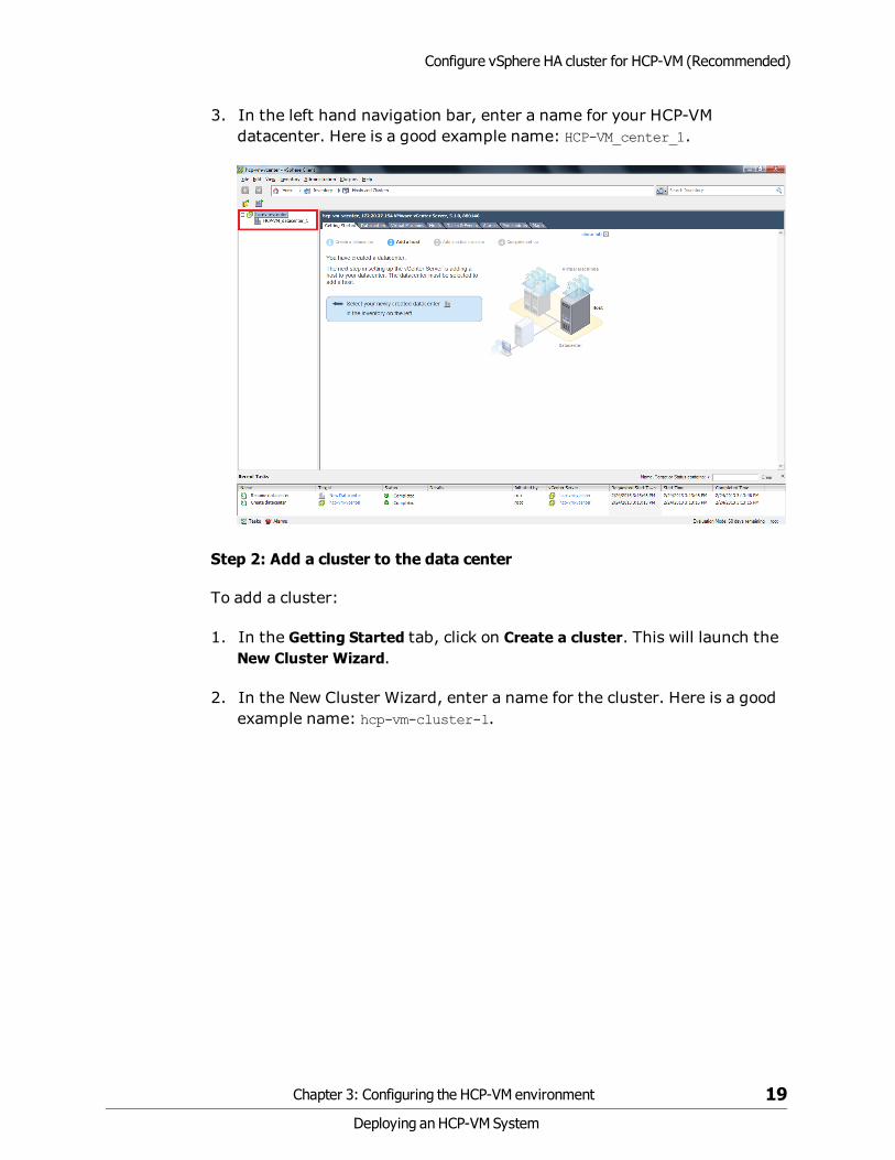
3. In the left hand navigation bar, enter a name for your HCP-VMdatacenter. Here is a good example name: HCP-VM_center_1.
Step 2: Add a cluster to the data center
To add a cluster:
1. In the Getting Started tab, click on Create a cluster. This will launch theNew Cluster Wizard.
2. In the New Cluster Wizard, enter a name for the cluster. Here is a goodexample name: hcp-vm-cluster-1.
Chapter 3: Configuring the HCP-VM environment 19
Deploying an HCP-VM System
Configure vSphere HA cluster for HCP-VM (Recommended)

3. Select Turn on vSphere HA.
Important: Do not click Turn on vSphere DRS.
Note: DRS can be turned on later to define VM affinity to a particular hostor group of hosts. This function does not provide further automation offailover. The settings described merely assist with keeping VMs on aparticular host, and alert if the rule cannot be followed. See appendix D fordetails on the settings required.
4. Click Next.
20 Chapter 3: Configuring the HCP-VM environment
Deploying an HCP-VM System
Configure vSphere HA cluster for HCP-VM (Recommended)

5. Select the Enable Host Monitoring checkbox.
6. Select Enable: Disallow VM power on operations that violate availabilityconstraints.
7. Select Host failures the cluster tolerates and set the value to 1.
8. Click Next.
Chapter 3: Configuring the HCP-VM environment 21
Deploying an HCP-VM System
Configure vSphere HA cluster for HCP-VM (Recommended)

9. Set the VM restart priority toMedium.
10.Set the Host Isolation response to Leave powered on.
11.Click Next.
22 Chapter 3: Configuring the HCP-VM environment
Deploying an HCP-VM System
Configure vSphere HA cluster for HCP-VM (Recommended)

12.Set VM Monitoring to Disabled.
13.Drag the Monitoring Sensitivity pointer to High.
14.Click Next.
Chapter 3: Configuring the HCP-VM environment 23
Deploying an HCP-VM System
Configure vSphere HA cluster for HCP-VM (Recommended)

15.Select Disable EVC.
16.Click Next.
24 Chapter 3: Configuring the HCP-VM environment
Deploying an HCP-VM System
Configure vSphere HA cluster for HCP-VM (Recommended)

17.Select Store the swap file in the same directory as the virtual machine(recommended).
18.Click Next.
Chapter 3: Configuring the HCP-VM environment 25
Deploying an HCP-VM System
Configure vSphere HA cluster for HCP-VM (Recommended)

19.Review your preferences. Makes sure they adhere to this manual.
20.Click Finish to create the new cluster.
26 Chapter 3: Configuring the HCP-VM environment
Deploying an HCP-VM System
Configure vSphere HA cluster for HCP-VM (Recommended)

Step 3: Add ESXi hosts to the HCP-VM cluster
To add ESXi hosts to the cluster:
1. On the vSphere Client home page, select the cluster you created on theleft side navigation bar.
2. In the Getting Started tab, click on Add a host.
Chapter 3: Configuring the HCP-VM environment 27
Deploying an HCP-VM System
Configure vSphere HA cluster for HCP-VM (Recommended)

3. In the Add Host Wizard, enter the ESXi host connection information.
4. Enter the ESXi host Username and Password.
5. Click Next.
28 Chapter 3: Configuring the HCP-VM environment
Deploying an HCP-VM System
Configure vSphere HA cluster for HCP-VM (Recommended)

6. Review the Host Information.
7. Click Next.
Chapter 3: Configuring the HCP-VM environment 29
Deploying an HCP-VM System
Configure vSphere HA cluster for HCP-VM (Recommended)

8. Enter the license information for the ESXi host if it doesn't have anyassigned.
9. Click Next.
30 Chapter 3: Configuring the HCP-VM environment
Deploying an HCP-VM System
Configure vSphere HA cluster for HCP-VM (Recommended)

10.Select Enable lock down mode if you want to prevent remote users fromlogging in directly.
Note: The decision to impliment lock down mode should be made by thecustomer.
11.Click Next.
Chapter 3: Configuring the HCP-VM environment 31
Deploying an HCP-VM System
Configure vSphere HA cluster for HCP-VM (Recommended)

12.Review your choices. Make sure they adhere to this guide.
13.Click Finish to add the ESXi host to the vSphere HA cluster.
14.Repeat Step 3 for all other ESXi hosts in the system.
After completing the configuration, it should be performed for all otherESXi hosts in the system.
Note:
• The number of ESXi hosts cannot exceed 32 (vSphere 5.0/5.1/5.5 HA clusterlimitation).
• If the number of hosts exceeds 32, a second vSphere Ha cluster needs to be createdwith the same settings in the same instance of vCenter.
• The ESXi hosts should be balanced between the two clusters.
• At this point, all hosts could have an alert that there aren't enough heartbeatdatastores.
– This can be verified by clicking on the host, selecting the Summary tab, andobserving the Configuration Issues at the top of the page.
32 Chapter 3: Configuring the HCP-VM environment
Deploying an HCP-VM System
Configure vSphere HA cluster for HCP-VM (Recommended)

Provisioning HCP-VM storage
When provisioning storage for use with HCP-VM, be sure to review andfollow the ESXi Storage Guide (ex 5.5: vSphere Storage for ESXi 5.5 andvCenter Server 5.5) as well as the relevant storage vendor's VMware bestpractices guide.
The following are guidelines for provisioning shared SAN storage for usewith HCP-VM with the recommended configuration:
• Datastores used for HCP-VM nodes must be backed by shared RAID6storage.
• Each datastore should only consist of one LUN.
• HCP-VM nodes cannot share datastores.
• All LUNs will be mapped to ESXi hosts in the vSphere HA cluster.
• All LUN IDs must be consistent across hosts. For example, LUN 1 shouldbe mapped to host 1, host 2, host 3 and host 4 as LUN 1.
– This is also true for VMDK and RDM.
– For Network File System (NFS), all ESXi hosts must mount theexport with the same datastore name.
• All SAN LUNs will have at least two paths (multipathing) presented tothe ESXi host.
• If fabric is connected, redundant FC switches will be deployed as part ofthe HCP-VM storage environment to ensure maximum availability.
– To ensure maximum data security, it is recommended to use WWNzoning (not port) for HCP-VM Zones.
• If loop is connected, redundant controllers must be provisioned for theHCP-VM storage environment to ensure maximum availability. Do notuse different ports on the same array controller.
• The HCP-VM VMDK OVF is configured with a 32GB OS LUN and two500GB data LUNs.
Chapter 3: Configuring the HCP-VM environment 33
Deploying an HCP-VM System
Provisioning HCP-VM storage

– Due to overhead (VMware, HCP system), you must configure 1.2 TBper LUN for each VMware datastore when using the default VMDKsize in the VMDK OVF.
– If the VMDK sizes included in the OVF need to be changed, refer toappendix C, "Appendix B: Changing the VMDK target size" onpage 141
The diagram below illustrates a sample SAN layout for VMDK and RDM. Thenumber of storage controller ports dedicated to an HCP-VM system isdependent on the capabilities of the storage array. For HDS mid-rangestorage the best practice is to spread host access across all cores.
Consult the storage vendor documentation for sizing and configurationoptions.
Fibre Channel Connectivity
34 Chapter 3: Configuring the HCP-VM environment
Deploying an HCP-VM System
Provisioning HCP-VM storage
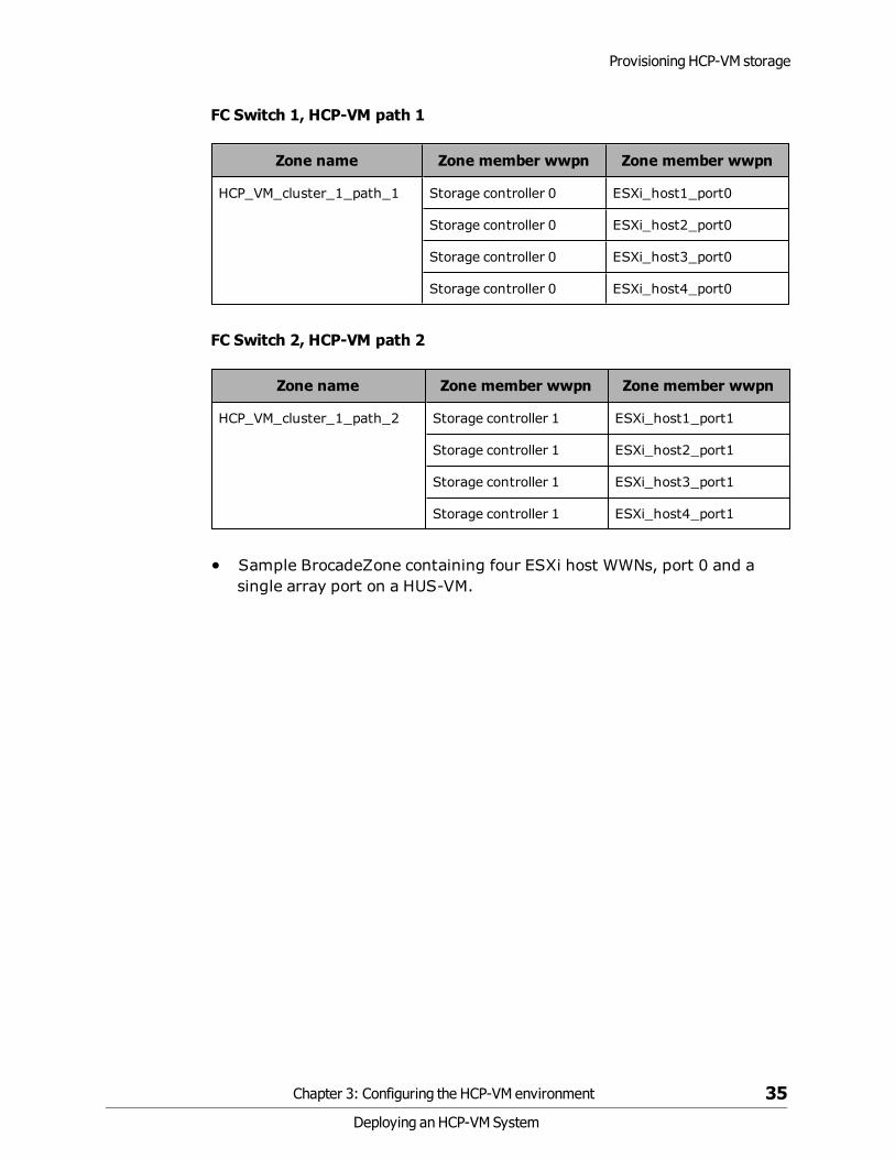
FC Switch 1, HCP-VM path 1
Zone name Zone member wwpn Zone member wwpn
HCP_VM_cluster_1_path_1 Storage controller 0 ESXi_host1_port0
Storage controller 0 ESXi_host2_port0
Storage controller 0 ESXi_host3_port0
Storage controller 0 ESXi_host4_port0
FC Switch 2, HCP-VM path 2
Zone name Zone member wwpn Zone member wwpn
HCP_VM_cluster_1_path_2 Storage controller 1 ESXi_host1_port1
Storage controller 1 ESXi_host2_port1
Storage controller 1 ESXi_host3_port1
Storage controller 1 ESXi_host4_port1
• Sample BrocadeZone containing four ESXi host WWNs, port 0 and asingle array port on a HUS-VM.
Chapter 3: Configuring the HCP-VM environment 35
Deploying an HCP-VM System
Provisioning HCP-VM storage

• Sample HostGroup / LUN layout displaying the same LUNs mapped withthe same HLUN to each ESXi host.
• This example assumes ESXi OS LUN has already been provisioned, but itcan be provisioned from the SAN as well.
– In the case of the OS LUN being provisioned on the SAN, only theESXi host that is booting from the LUN should be granted access.
Array path 1
Host Group Name Hosts HLUN ArrayLUN VMware datastore
HCP_VM_cluster_1_path_1
ESXi-1
ESXi-2
ESXi-3
ESXi-4
1 10 hcp-vm_cluster-1_node_1_datastore_1
2 11 hcp-vm_cluster-1_node_2_datastore_1
4 12 hcp-vm_cluster-1_node_3_datastore_1
5 13 hcp-vm_cluster-1_node_4_datastore_1
36 Chapter 3: Configuring the HCP-VM environment
Deploying an HCP-VM System
Provisioning HCP-VM storage

Array path 2
Host Group Name Hosts HLUN ArrayLUN VMware datastore
HCP_VM_cluster_1_path_2
ESXi-1
ESXi-2
ESXi-3
ESXi-4
1 10 hcp-vm_cluster-1_node_1_datastore_1
2 11 hcp-vm_cluster-1_node_2_datastore_1
4 12 hcp-vm_cluster-1_node_3_datastore_1
5 13 hcp-vm_cluster-1_node_4_datastore_1
This following image is an example of Storage Navigator view showing fourdatastores and LUN masking.
Note: Note that the same HLUN/LUN combination is assigned to all ESXihosts.
Chapter 3: Configuring the HCP-VM environment 37
Deploying an HCP-VM System
Provisioning HCP-VM storage

Add datastores to vSphere HA cluster
It is recommended to have only one LUN from a RAID Group in the HCP-VMsystem. Adding multiple LUNs from the same RAID Group increases the riskof data lose in the event of a failure.
A datastore can only be set for one HCP-VM node, but each HCP-VM nodecan have multiple datastores.
During the initial OVF deploy, three VMDK’s will be created from the initialdatastore space. One 32GB OS LUN, and two 500GB data LUNs.
The largest VMDK that VMware 5.0 and 5.1 currently supports is 2TB. Thelargest VMDK that VMware 5.5 supports is 64TB. Currently, 2TB is thelargest a disk can be in an HCP-VM system using VMDKs.
Here is a visual depiction of the cluster layout.
38 Chapter 3: Configuring the HCP-VM environment
Deploying an HCP-VM System
Add datastores to vSphere HA cluster

To add datastores to vSphere HA clusters:
1. Access your vSphere Client.
2. In the left side navigation bar, click on the top ESXi host in your HCP-VMcluster.
3. In the right side window, click on the Configuration tab.
4. Click on Storage under the Hardware section.
5. In the Datastores section, click on Add Storage, located at the top rightof the window.
Chapter 3: Configuring the HCP-VM environment 39
Deploying an HCP-VM System
Add datastores to vSphere HA cluster

6. In the Add Storage window, select Disk/LUN.
7. Click Next.
40 Chapter 3: Configuring the HCP-VM environment
Deploying an HCP-VM System
Add datastores to vSphere HA cluster

8. Select the appropriate LUN in the list.
9. Click Next.
10.Select VMFS-5.
11.Click Next.
Chapter 3: Configuring the HCP-VM environment 41
Deploying an HCP-VM System
Add datastores to vSphere HA cluster

12.Review the the Current Disk Layout information.
13.Click Next.
14.Enter a meaningful name for the datastore. A good example name is:hcp-vm_cluster_1_node_1_datastore_1.
15.Click Next.
42 Chapter 3: Configuring the HCP-VM environment
Deploying an HCP-VM System
Add datastores to vSphere HA cluster
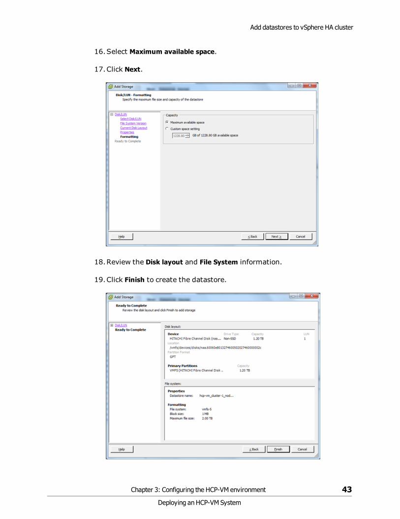
16.Select Maximum available space.
17.Click Next.
18.Review the Disk layout and File System information.
19.Click Finish to create the datastore.
Chapter 3: Configuring the HCP-VM environment 43
Deploying an HCP-VM System
Add datastores to vSphere HA cluster

The datastore should now be initialized and mounted. If it is, then in theRecent Tasks section, at the bottom of the vSphere Client, a Rescan VMFSalarm should be issued for all other ESXi hosts in the cluster.
The new datastore should be automatically added to the inventory of all theother ESXi hosts.
Repeat the adding storage procedure for the other datastore LUNs with allthe same values and verification except for the datastore name.
44 Chapter 3: Configuring the HCP-VM environment
Deploying an HCP-VM System
Add datastores to vSphere HA cluster

Here are examples of other identifiable datastore names you can use:
• LUN2 = hcp-vm_cluster_1_node_2_datastore_1
• LUN4 = hcp-vm-cluster_1_node_3_datastore_1
• LUN5 = hcp-vm-cluster_1_node_4_datastore_1
Once everything is completed, select the ESXi host and go to theConfiguration tab. Click on the Storage under the Hardwaresection. EachESXi host should appear with all datastores tagged with a normal status.
Chapter 3: Configuring the HCP-VM environment 45
Deploying an HCP-VM System
Add datastores to vSphere HA cluster

Alert should no longer appear for each ESXi node because there are now twodatastores available for heartbeating.
Next, click on the Configuration tab, and click on Storage Adapters under theHardware section. Make sure that the Operational State is Mounted for bothpaths.
46 Chapter 3: Configuring the HCP-VM environment
Deploying an HCP-VM System
Add datastores to vSphere HA cluster

Path 1
Chapter 3: Configuring the HCP-VM environment 47
Deploying an HCP-VM System
Add datastores to vSphere HA cluster

Path 2
NFS Datastores
You can configure HNAS file systems and their underlying storage in avariety of different ways. To achieve the best performance, follow theserecommendations for configuring HNAS in a VMware vSphere environment:
• In general, a 4 KB file system block size is recommended. 32 KB can beused in instances where all VMs on a specific HNAS file system performlarge block requests.
• Set cache-bias to large (cache-bias --large-files).
• Disable shortname generation and access time maintenance (shortname–g off, fs-accessed-time --file-system <file_system> off).
48 Chapter 3: Configuring the HCP-VM environment
Deploying an HCP-VM System
NFS Datastores
• Disable the quick start option for HNAS read ahead when VM IO profilesare primarily random. (read-ahead --quick-start disable).
• NFS exports: Do not export the root of the file system.
• File system utilization: Maintain at least 10% free space in each filesystem utilized by ESXi hosts.
• Storage pools: Do not mix disk types in the same storage pool.
• Limit ownership of all file systems that are created on a storage pool toone EVS.
• Configure a minimum of four (4) System Drives (SD) in a storage pool.
• Configure one (1) LU\LDEV per RAID group consuming all space (ifpossible).
Creating an NFS datastore
To set up an NFS datastore follow these steps:
1. Access your VMware Virtual Infrastructure client.
2. In the left side navigation window, select an ESXi host.
3. In the right hand window, click on the Configuration tab.
4. Under the Hardware section in the right hand window, click Storage.
5. In the upper right hand corner of the right hand window, click on AddStorage(SCSI, SAN, and NFS).
6. In the Storage Type window, select the Network File System storagetype.
7. Click Next.
8. In the Locate Network File System window, enter the NAS server name,the folder, and the datastore name,
9. Click Next.
10.Review your set up and click Finish.
Chapter 3: Configuring the HCP-VM environment 49
Deploying an HCP-VM System
Creating an NFS datastore

Important: Ensure that you mount datastores with the same volumelabel on all vSphere ESXi hosts within VMware high availability (HA)environments.
Heartbeat datastore selection
The Heartbeat Datastore function monitors hosts and Virtual Machines ifthe management network fails.
50 Chapter 3: Configuring the HCP-VM environment
Deploying an HCP-VM System
Heartbeat datastore selection

To activate Heartbeat datastore:
1. Access your vSphere Client.
2. On the left side navigation bar, right click on the cluster and in the submenu click Edit Settings.
3. In the Settings window, select Datastore Heartbeating from the left sidenavigation bar.
4. Select four HCP-VM datastores.
5. Enable the option to Select any of the cluster datastores and mimic thepreferences shown in the image below.
6. Click OK to commit the settings.
Preparing the ESXi network for the HCP-VM OVFdeployment
For optimal performance, security, and high availability of an HCP-VMsystem, it is recommended to provide exclusive use of two physical NICs pernode. These are used for private, Back-end communication within the
Chapter 3: Configuring the HCP-VM environment 51
Deploying an HCP-VM System
Preparing the ESXi network for the HCP-VM OVF deployment

system. The Back-end network is responsible for such things as HCPHeartbeating and data traffic.
The Back-end NICs should be connected to dedicated, redundant Ethernetswitches with spanning tree disabled and multi-cast enabled. Multi-castshould be configured for its vendor's specifications.
If the HCP-VM system is going to utilize dvSwitches, consult relevantVMware and vendor documentation for best practices.
Each HCP-VM node should have a least one physical NIC used for dataaccess and system management. If utilizing 802.3ad in the customerenvironment, plan accordingly and follow VMware's best practices forconfiguration.
If the HCP-VM system is going to be used with the virtual networkmanagement feature, follow the guide in appendix B.
If the HCP-VM system will use NFS datastores, be sure to add the VM Kerneldevice for IP networking. Consult VMware documentation for more detailson configuring ESXi with NFS datastores.
Configuring the Storage Network (HNAS Best Practice)
The IP protocol storage uses the TCP/IP stack as its foundation forcommunication. The stack includes Internet Small Computer SystemInterface iSCSI and Network Access Server NAS for ESXi hosts. A VMkerneluses the TCP/IP protocol stack to handle the data transport. Make sure theNFS server is enabled on all ESXi hosts.
To create a VMkernel:
1. Access the vSphere client.
2. On the left side navigation bar, select an ESXi host.
3. Click on the Configuration tab in the right side window.
4. In the Hardware section, click on Networking.
5. In the top right quadrant of the right side window, click on AddNetworking.
6. In the Add Network Wizard window, select VMkernel.
7. Click Next.
52 Chapter 3: Configuring the HCP-VM environment
Deploying an HCP-VM System
Preparing the ESXi network for the HCP-VM OVF deployment
8. Select one of the Physical Network Cards.
9. Click Next.
10. In the Network Label text box, enter VMkernel.
11.Click Next.
12.Enter the IP address and the subnet mask.
13.To provide the VMkernel default gateway, click Edit and enter thegateway address.
14.Click OK.
15.Back in the Wizard, click Next.
16.Click Finish.
Note:
• If using large 2TB NFS datastores, increase RPC timeout.
• HDS recommends that the VMkernel network be set up in a private network or with aunique VLAN ID that provides network isolation. For a full list of HDSrecommendations for HNAS NFS datastores, review Hitachi NAS Platform BestPractices Guide for NFS with VMware vSphere.
Configuring networking for Front-end switching
The HCP Front-end network needs to be configured so that it can performsystem management and provide client access. You are responsible forconfiguring the network.
Chapter 3: Configuring the HCP-VM environment 53
Deploying an HCP-VM System
Preparing the ESXi network for the HCP-VM OVF deployment

To configure the front end network:
1. Access the vSphere client.
2. In the left side navigation bar, select the first ESXi host.
3. In the right side window, click on the Configuration tab.
4. Click on Networking in the Hardware section.
5. Click Properties button located in the center of the right hand window.
Note: There are multiple property buttons on the page. Make sure to clickthe right one or you will not open the appropriate window.
6. In the vSwitch Properties window, click on the Network Adapters tab.
7. Verify that the correct vmNICs are part of the Front-end Network. Ifthey are incorrect:
a. Add the correct vmNICs
b. Remove the incorrect vmNICS.
54 Chapter 3: Configuring the HCP-VM environment
Deploying an HCP-VM System
Preparing the ESXi network for the HCP-VM OVF deployment

8. Click on the Ports tab.
9. In the left side window, select VM Network and click Edit.
Chapter 3: Configuring the HCP-VM environment 55
Deploying an HCP-VM System
Preparing the ESXi network for the HCP-VM OVF deployment

10.In the VM Network Properties window, change the Network Label toFront-end Network. Do NOT click OK.
56 Chapter 3: Configuring the HCP-VM environment
Deploying an HCP-VM System
Preparing the ESXi network for the HCP-VM OVF deployment

11.Click on the NIC Teaming tab.
Chapter 3: Configuring the HCP-VM environment 57
Deploying an HCP-VM System
Preparing the ESXi network for the HCP-VM OVF deployment

12.In the NIC Teaming tab, select the first four check boxes, and select thefollowing for the drop down menus:
a. For Load Balancing select Use explicit failover order.
b. For Network Failover Detection select Link status only.
c. For Notify Switches select Yes.
d. For Failback select Yes.
13.Click OK.
14. In the vSwitch Properties window, click Close.
58 Chapter 3: Configuring the HCP-VM environment
Deploying an HCP-VM System
Preparing the ESXi network for the HCP-VM OVF deployment

15.Repeat the steps to configure the Front-end Network for each ESXi hostthat will be part of the HCP-VM system.
Configure networking for Back-end switching
The HCP private Back-end network needs to be configured so that it canprovide inter-node communication and data transfer. You are responsiblefor configuring the network.
To configure the back-end network for switching:
1. Access the vSphere Client.
2. In the left side navigation bar, select the first ESXi host.
3. In the right side window, click on the Configuration tab.
4. Click on Networking in the Hardware section.
5. Click Add Networking button located in the top right of the right handwindow.
6. In the Add Network Wizard select Virtual Machine.
7. Click Next.
Chapter 3: Configuring the HCP-VM environment 59
Deploying an HCP-VM System
Preparing the ESXi network for the HCP-VM OVF deployment

8. Select the Physical NIC to use for the Back-end network.
9. Click Next.
10.Name the Network label Back-End.
11.Click Next.
60 Chapter 3: Configuring the HCP-VM environment
Deploying an HCP-VM System
Preparing the ESXi network for the HCP-VM OVF deployment

12.Review your changes and click Finish.
13.Repeat the steps to configure the Back-end Network for each ESXi hostthat will be part of the HCP-VM system.
Verifying ESXi configuration on all hosts
The Front-end and Back-end networks must be configured for each ESXihost added to the HCP-VM system. To make sure that all changes arecorrect, select a single ESXi host on the left side navigation bar, and click onthe Configuration tab in the right side window. Beginning with Processors,click each components listed in the Hardware section and make that theirspecifications matches the images below.
No changes have been made to the Advanced Settings or PowerManagement sections.
Important: Repeat this verification on all ESXi hosts in the vSphere HAcluster.
Chapter 3: Configuring the HCP-VM environment 61
Deploying an HCP-VM System
Preparing the ESXi network for the HCP-VM OVF deployment
Processors
62 Chapter 3: Configuring the HCP-VM environment
Deploying an HCP-VM System
Preparing the ESXi network for the HCP-VM OVF deployment

Memory
Chapter 3: Configuring the HCP-VM environment 63
Deploying an HCP-VM System
Preparing the ESXi network for the HCP-VM OVF deployment

Storage
64 Chapter 3: Configuring the HCP-VM environment
Deploying an HCP-VM System
Preparing the ESXi network for the HCP-VM OVF deployment

Networking
Chapter 3: Configuring the HCP-VM environment 65
Deploying an HCP-VM System
Preparing the ESXi network for the HCP-VM OVF deployment

Storage Adapters
66 Chapter 3: Configuring the HCP-VM environment
Deploying an HCP-VM System
Preparing the ESXi network for the HCP-VM OVF deployment

Verify Network Adapters
Chapter 3: Configuring the HCP-VM environment 67
Deploying an HCP-VM System
Preparing the ESXi network for the HCP-VM OVF deployment

68 Chapter 3: Configuring the HCP-VM environment
Deploying an HCP-VM System

Creating the HCP-VM system
For general installation recommendations, prior to performing the HCPsoftware installation on an HCP-VM system, review the documentation forInstalling an HCP System.
Unpacking the OVF Zip file
On your computer, access the DVD that contains the virtual machine imagefile and unpack the zip vmdkIso: HS421_x.x.x.x.iso.zip or the zip rdmIso:HS433_x.x.x.x.iso.zip file into a directory of your choice.
To unpack the file that contains the virtual machine image:
1. On your computer, unpack the zip vmdkIso: HS421_x.x.x.x.iso.zip orthe zip rdmIso: HS433_x.x.x.x.iso.zip file into a directory of your choice.
2. Navigate into the folder you unpacked the zip.
3. Unpack the ISO files vmdkIso: HS421_x.x.xx.iso or the rdmIso:HS433_x.x.x.x.iso.
Deploying the HCP-VM OVF VDMK
There are two different OVFs that can be deployed. These steps are for theVMDK deploy. The RDM procedure is identical to this one except for someminor differences. You only need to install one of them.
Step 1: Log into the ESXi server
To deploy the HCP-VM OVF:
1. Launch the vSphere client.
Chapter 4: Creating the HCP-VM system 69
Deploying an HCP-VM System
4

2. Enter the IP address / Name, or select the correct information from thedrop down menu to connect to the vCenter server where the vSphere HAcluster was configured for the HCP-VM system.
3. Enter the User name and Password.
4. Click Login.
70 Chapter 4: Creating the HCP-VM system
Deploying an HCP-VM System
Deploying the HCP-VM OVF VDMK

5. Once logged in to the vSphere Client, you should see the datacenters,clusters and ESXi nodes on the left side navigation bar that werepreviously added to vCenter.
6. In the navigation bar on the left hand side, select the ESXi host totarget for the deploy and click File in the toolbar at the top of the screenand in the submenu click Deploy OVF Template.
Chapter 4: Creating the HCP-VM system 71
Deploying an HCP-VM System
Deploying the HCP-VM OVF VDMK

Step 2: Deploy VMDK OVF Template
1. In the Deploy OVF Template window, click on the Browse button andnavigate to the local file system to the location that HS421_7.0.XX.zipyou extracted.
2. Select the HCP-VM-VMDK.ovf file and click Open.
72 Chapter 4: Creating the HCP-VM system
Deploying an HCP-VM System
Deploying the HCP-VM OVF VDMK

3. Once the path to the OVF file has been selected, click Next .
Chapter 4: Creating the HCP-VM system 73
Deploying an HCP-VM System
Deploying the HCP-VM OVF VDMK
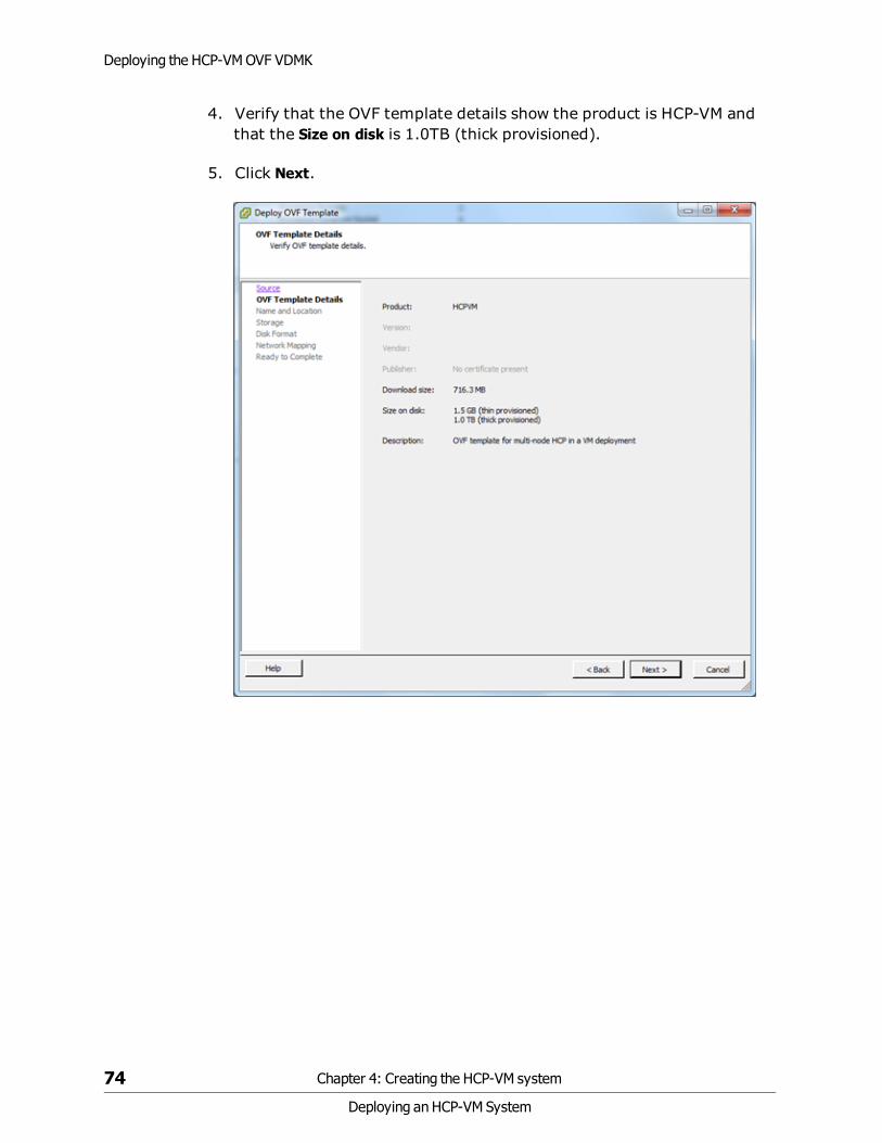
4. Verify that the OVF template details show the product is HCP-VM andthat the Size on disk is 1.0TB (thick provisioned).
5. Click Next.
74 Chapter 4: Creating the HCP-VM system
Deploying an HCP-VM System
Deploying the HCP-VM OVF VDMK

6. Enter a name for the node that is being deployed. It should be namedsomething meaningful for the installation. For example: hcp-vm_cluster-1_node_1.
7. Once the name has been entered, click Next.
Chapter 4: Creating the HCP-VM system 75
Deploying an HCP-VM System
Deploying the HCP-VM OVF VDMK

8. Select 1 datastore from the list you previously added to the ESXi hosts.If you're doing a consecutive load, make sure to select the nextdatastore down (from the previous load) on the list. The selecteddatastore should have a capacity of at least 1.2TB.
9. Click Next.
76 Chapter 4: Creating the HCP-VM system
Deploying an HCP-VM System
Deploying the HCP-VM OVF VDMK

10.Verify that the datastore you selected matches the Available spaceexpected for the datastore.
11.Select Thick Provision Eager Zeroed.
12.Click Next.
Chapter 4: Creating the HCP-VM system 77
Deploying an HCP-VM System
Deploying the HCP-VM OVF VDMK

13. Hover your cursor over a Destination network to make a drop downmenu button appear. Click on the drop down menu for DestinationNetworks.
14.Change the Destination Networks so that the Front-end Network alignswith the BuildVMDisk Network.
15.Change the Destination Networks so that the Back-end Network alignswith the Virtual Back-end Network.
78 Chapter 4: Creating the HCP-VM system
Deploying an HCP-VM System
Deploying the HCP-VM OVF VDMK

16.Verify the Destination Networks mimic the following image.
17.Click Next.
Important: DoNOT select the Power on checkbox.
Chapter 4: Creating the HCP-VM system 79
Deploying an HCP-VM System
Deploying the HCP-VM OVF VDMK

18.Verify the information in Deployment settings matches what waspreviously entered:
a. If so click on Finish to begin the OVF deploy.
b. If not, go back and correct any information that needs to bechanged.
Important:
• The VMDKOVF deploy can take up to an hour or more. This is due to the fact thatVMware is preparing the vmdk’s for use by the HCP-VM node. There will not be anyindication of progress in the OVF deploy window (just a spinning cursor) or in thedeploy task at the bottom of vSphere client (just “in progress”). The only indicationwill come when checking the available capacity of the datastore. This will show adecrease in available capacity when the first vmdk has been prepared.
• You must repeat the OVF deployment for each of the nodes that are going to be partof the HCP-VM system.
• Make sure that you have highlighted the desired ESXi host that you want the HCP-VMnode to run on initially before importing the OVF.
80 Chapter 4: Creating the HCP-VM system
Deploying an HCP-VM System
Deploying the HCP-VM OVF VDMK

Once the OVF Deploy is completed, you will see the following message.
Deploy the HCP-VM OVF RDM
There are two different OVFs that can be deployed. These steps are for theRDM deploy. The VDMK procedure is identical to this one except for someminor differences. You only need to install one of them.
Step 1: Log into the ESXi server
To deploy the HCP-VM OVF:
1. Launch the vSphere client.
Chapter 4: Creating the HCP-VM system 81
Deploying an HCP-VM System
Deploy the HCP-VM OVF RDM

2. Enter the IP address / Name, or select the correct information from thedrop down menu to connect to the vCenter server where the vSphere HAcluster was configured for the HCP-VM system.
3. Enter the User name and Password.
4. Click Login.
82 Chapter 4: Creating the HCP-VM system
Deploying an HCP-VM System
Deploy the HCP-VM OVF RDM

5. Once logged in to the vSphere Client, you should see the datacenters,clusters and ESXi nodes that were previously added to vCenter in theleft side navigation bar.
6. In the navigation bar on the left hand side, select the ESXi host totarget for the deploy and click File > Deploy OVF Template from thetoolbar at the top of the screen.
Chapter 4: Creating the HCP-VM system 83
Deploying an HCP-VM System
Deploy the HCP-VM OVF RDM

Step 2: Deploy RDM OVF Template
1. In the Deploy OVF Template window, click on the Browse button andnavigate to the local file system to the location that HS433_7.0.XX.zipyou extracted.
2. Select the HCP-VM-RDM.ovf file and click Open.
84 Chapter 4: Creating the HCP-VM system
Deploying an HCP-VM System
Deploy the HCP-VM OVF RDM

3. Once the path to the OVF file has been selected, click on Next to proceedwith the Deploy OVF Template wizard.
Chapter 4: Creating the HCP-VM system 85
Deploying an HCP-VM System
Deploy the HCP-VM OVF RDM

4. Verify that the OVF template details show that the product is HCP-VMand the Size on disk is 32.0GB (thick provisioned).
5. Click Next.
86 Chapter 4: Creating the HCP-VM system
Deploying an HCP-VM System
Deploy the HCP-VM OVF RDM

6. Enter a name for the node that is being deployed. It should be namedsomething meaningful for the installation. For example: HCPVM-node-1.
7. Once the name has been entered, click Next.
Chapter 4: Creating the HCP-VM system 87
Deploying an HCP-VM System
Deploy the HCP-VM OVF RDM

8. Select 1 datastore from the list you previously added to the ESXi hosts.If you're doing a consecutive load, make sure to select the nextdatastore down (from the previous load) on the list. The selecteddatastore should have a capacity of 50GB.
9. Click Next.
88 Chapter 4: Creating the HCP-VM system
Deploying an HCP-VM System
Deploy the HCP-VM OVF RDM

10.Verify that the datastore you selected matches the Available space sizeexpected for the datastore.
11.Select Thick Provision Eager Zeroed.
12.Click Next.
Chapter 4: Creating the HCP-VM system 89
Deploying an HCP-VM System
Deploy the HCP-VM OVF RDM

13.Hover your cursor over a Destination network to make a drop downmenu button appear. Click on the drop down menu for DestinationNetworks.
14.Change the Destination Networks so that the Front-end Network lines upwith the BuildVMDisk Network.
15.Change the Destination Networks so that the Back-end Network lines upwith the Virtual Back-end Network.
90 Chapter 4: Creating the HCP-VM system
Deploying an HCP-VM System
Deploy the HCP-VM OVF RDM

16.Verify your Destination Networks are set the same way as in the imagebelow.
17.Click Next.
Important: DoNOT select the Power on checkbox.
Chapter 4: Creating the HCP-VM system 91
Deploying an HCP-VM System
Deploy the HCP-VM OVF RDM

18.Verify the information in Deployment settings matches what waspreviously entered:
a. If so click on Finish to begin the OVF deploy.
b. If not, go back and correct any information that needs to bechanged.
Important:
• You must repeat the OVF deployment for each of the nodes that are going to be partof the HCP-VM system.
• Make sure that you have highlighted the desired ESXi host that you want the HCP-VMnode to run on initially before importing the OVF.
92 Chapter 4: Creating the HCP-VM system
Deploying an HCP-VM System
Deploy the HCP-VM OVF RDM

Once the OVF Deploy is completed, you will see the following message.
Step 3: Complete the Deployment
To complete the deployment:
1. After the OVFs have deployed successfully, in the left side navigationbar right click on the HCP-VM and select Edit Settings.
2. In the Settings window, click Add.
3. In the Add Hardware window, select Hard Disk.
4. Click Next.
Chapter 4: Creating the HCP-VM system 93
Deploying an HCP-VM System
Deploy the HCP-VM OVF RDM

5. Select Raw Device Mapping.
6. Click Next.
7. Select the desired LUN.
8. Click Next.
94 Chapter 4: Creating the HCP-VM system
Deploying an HCP-VM System
Deploy the HCP-VM OVF RDM

9. Select Store with Virtual Machine.
10.Click Next.
11.Select Physical.
12.Click Next.
Chapter 4: Creating the HCP-VM system 95
Deploying an HCP-VM System
Deploy the HCP-VM OVF RDM

13.Select the next SCSI device.
14.Click Next.
96 Chapter 4: Creating the HCP-VM system
Deploying an HCP-VM System
Deploy the HCP-VM OVF RDM

15.Review your actions and click Finish.
16.Repeat the steps to add a second data LUN.
Important: DoNOT power on the HCP-VM yet.
Configuring HCP-VM network
After deploying the OVF, the following steps need to be performed for allHCP-VM nodes in the vSphere cluster. They must be done in this order:
1. Power on the first node.
2. Follow the configuration instructions below.
3. Repeat for the next node in the HCP-VM system.
Note: Before continuing with this procedure, you will need the front-end IPaddresses, network mask, default gateway and Back-end IP addresses fromthe network administrator at the customer site. All Back-end IP addressesmust be on the same subnet. For easier installations and support, requestthe last octet of the Front-end and Back-end be sequential.
Chapter 4: Creating the HCP-VM system 97
Deploying an HCP-VM System
Configuring HCP-VM network

To configure the HCP-VM network:
1. Access the vSphere Client.
2. In the left side navigation bar, right click on the lowest numbered nodeand click on Open Console.
3. Login to the HCP-VM node console with the default login information:
– Username: install
– Password: Chang3Me!
98 Chapter 4: Creating the HCP-VM system
Deploying an HCP-VM System
Configuring HCP-VM network
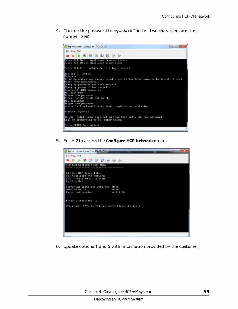
4. Change the password to hcpinsta11(The last two characters are thenumber one).
5. Enter 2 to access the Configure HCP Networkmenu.
6. Update options 1 and 5 with information provided by the customer.
Chapter 4: Creating the HCP-VM system 99
Deploying an HCP-VM System
Configuring HCP-VM network

7. Ignore option 4 unless the customer wants to deploy with VLAN supportturned on. See appendix A for configuring the ESXi Networking tosupport this.
8. For the example system, the following was changed and is reflected inthe next image:
– Front-end IP: 172.20.27.150
– Gateway address: 172.20.27.254
– Back-end IP: 172.21.150.150
Note: For configuring separate clusters, if you use similar Back-end IPs thethird octet has to be unique, otherwise the nodes will communicate acrossclusters.
100 Chapter 4: Creating the HCP-VM system
Deploying an HCP-VM System
Configuring HCP-VM network

9. Confirm the information and enter B to commit the changes.
10.Press enter to reboot the HCP-VM node.
11.The HCP-VM node will begin to reboot. Do not touch it until the reboot iscomplete.
Note: The previous steps must be completed for each VM you set up.
Chapter 4: Creating the HCP-VM system 101
Deploying an HCP-VM System
Configuring HCP-VM network

12.Once the HCP-VM node finishes rebooting, login with the username andpassword:
– Username: install
– Password: hcpinsta11
Install HCP software
The HCP install is performed from the node with the highest last octet in itsBack-end IP address. For example, the four Back-end IP addresses for theexample system are:
• 172.21.150.150
• 172.21.150.151
• 172.21.150.152
• 172.21.150.153
So 172.21.150.153 is the proper node for the HCP software installation.
To install the HCP software:
1. Access the vSphere client.
102 Chapter 4: Creating the HCP-VM system
Deploying an HCP-VM System
Install HCP software

2. In the left side navigation bar, select a console under 172.20.27.153(hcp-vm_cluster-1_node_4).
3. Right click on the console and click on Open Console.
4. Login with the username and password:
– Username: install
– Password: hcpinsta11
5. Enter 3.
6. Hit Enter.
Identify the nodes in the HCP system
The nodes in the HCP system need to be identified by the Back-end IPbefore the HCP system can be configured.
To identify the nodes:
1. From the HCP Configuration menu, enter 3 to run the HCP Setup wizard.
Chapter 4: Creating the HCP-VM system 103
Deploying an HCP-VM System
Install HCP software

2. In response to the confirming prompt, enter y or yes to confirm yourentry or n or no to try again.
When you enter y or yes, the HCP Setup wizard New Installmenuappears.
104 Chapter 4: Creating the HCP-VM system
Deploying an HCP-VM System
Install HCP software

3. Enter 1 to identify the nodes in the HCP system.
The HCP Nodes menu appears.
Chapter 4: Creating the HCP-VM system 105
Deploying an HCP-VM System
Install HCP software

4. Enter 1 to identify the storage nodes in the HCP system.
5. Use the Back-end IP address to identify each node.
Tip: If you chose to enter the node IP addresses as literal values, enter theIP address of the lowest-numbered node first. For subsequent IPaddresses, HCP Setup presents a default value that’s one greater than theprevious one you entered.
106 Chapter 4: Creating the HCP-VM system
Deploying an HCP-VM System
Install HCP software

6. From the HCP Nodes menu, enter b to return to the New Installmenu.
The New Installmenu now includes additional options for configuringthe HCP system.
Configure the HCP system
From the New Installmenu, execute the additional options for configuringthe HCP system. Each option either opens a lower-level menu withconfiguration options, or leads directly to a configuration option.
Chapter 4: Creating the HCP-VM system 107
Deploying an HCP-VM System
Install HCP software

To configure the HCP system:
1. Enter 2 in the New Installmenu to open the Key Access menu.
2. Change the distributor key.
Tip: If this is an HDS provided system, keep the default Arizona key.
3. Enter y or yes to confirm the change and return to the New Installmenu.
108 Chapter 4: Creating the HCP-VM system
Deploying an HCP-VM System
Install HCP software

4. Enter 3 to open the HCP Networkingmenu.
5. Enter 1 and change the Gateway router IP address.
6. Enter 2 and change the Multicast Network.
7. Enter b to return to the New Installmenu.
Chapter 4: Creating the HCP-VM system 109
Deploying an HCP-VM System
Install HCP software

8. Enter 4 to open the HCP DNS Options menu.
9. Enter 2 to input the domain name for the system.
10.Enter the system domain name.
110 Chapter 4: Creating the HCP-VM system
Deploying an HCP-VM System
Install HCP software

11.If Option 1: Enable DNS is not set to yes, change it to yes.
12. If Option 3: DNS Servers is not set to the proper corporate DNS server,change it accordingly.
13.Enter b to return to the New Installmenu.
14.Enter 5 open the HCP Time Options menu.
15.Enter 1 and set the time configuration to an external time server. Usethe same time server that has been configured for all ESXi hosts in theHCP-VM system.
This was set up in the "Enabling NTP for the ESXi hosts" on page 15.
Chapter 4: Creating the HCP-VM system 111
Deploying an HCP-VM System
Install HCP software

16.Enter an external time server.
17.Enter 6 to change the internal settings.
18.Select Internal.
112 Chapter 4: Creating the HCP-VM system
Deploying an HCP-VM System
Install HCP software

19.If you specify internal storage, select the option to set the serial numberfor the system.
20.Decide if replication will be enabled.
If you enter yes to enable replication, the wizard asks if this is areinstallation of a primary system after a replication failover with DNSfailover enabled. If you enter yes to this prompt, it requests that targetreplicated namespaces in this system will continue to be redirected tothe replica until data recovery is complete, provided that thosenamespaces are configured to accept such requests.
Important: Do not enable replication if you have not purchased thisfeature. Doing so makes the system violate your license agreement.
• Contact information for HCP customer support.
21.To specify no contact information, hit space.
22.Enter 7 to enable encryption.
Chapter 4: Creating the HCP-VM system 113
Deploying an HCP-VM System
Install HCP software

Execute the installation
If you enabled encryption in the previous section, have your securityadministrator present for this step. The security administrator should bethe only person to see the encryption key.
To execute the HCP software installation:
1. From the New Installmenu, enter x.
The wizard should display the following information.
114 Chapter 4: Creating the HCP-VM system
Deploying an HCP-VM System
Install HCP software

2. Review the configuration.
3. Perform one of the following steps:
a. If the configuration is not correct:
1. Enter n or no.
2. In response to the confirmation prompt, enter y or yes.
3. Correct any mistakes you made in the previous sections.
b. If the configuration is correct:
1. Enter y or yes.
2. In response to the confirmation prompt, enter y or yes.
When you enter y or yes, HCP Setup performs a set of installation prechecksand, if they are successful, installs the HCP software on all nodes in thesystem. This can take from several minutes to several hours, depending onthe size of the logical volumes.
Important: If you enabled encryption in the system configuration, HCPSetup displays the encryption key after doing some initial setup. It thenprompts you to enter the key. Before entering the encryption key, write itdown on paper.
Chapter 4: Creating the HCP-VM system 115
Deploying an HCP-VM System
Install HCP software

After you enter the key, HCP Setup proceeds with the installation. You donot get a second chance to see the encryption key, and the key is not storedfor later retrieval.
When the installation is complete, HCP Setup logs you out and reboots thenodes. The console then displays the login prompt.
If HCP Setup exits at any time before the installation processing iscomplete, make a note of all error messages and then contact yourauthorized HCP service provider for help.
Beginning of HCP install. Pre-checks for system health.
116 Chapter 4: Creating the HCP-VM system
Deploying an HCP-VM System
Install HCP software

HCP installation formatting the data LUNs.
After the installation is complete, the HCP-VM nodes will all reboot, andinstead of the aos login prompt you should see an hcp-node-<nodeNumber>prompt.
After the reboot, you can also check the runlevel of the node by hittingAlt+F5 when inside the console.
Chapter 4: Creating the HCP-VM system 117
Deploying an HCP-VM System
Install HCP software

Verifying the HCP installation
Access the HCP System Management Console to verify that the HCP systeminstalled correctly.
To verify the HCP system installation:
1. Open the System Management Console by entering one of the followingURLs in a web browser on a client computer:
– If the HCP system is configured for DNS - https://admin.hcp-domain-name:8000
– If the HCP system is not configured for DNS - https://node-ip-address:8000
Node-ip-address is the Front-end IP address of any storage node in the HCPsystem.
Note: If you inadvertently use http instead of https in the URL, thebrowser returns an error. Enter the URL again, this time using https.
2. When prompted, accept the self-signed HCP SSL server certificate eitherpermanently or temporarily. Set a temporary certificate if you plan to installa trusted certificate later on.
The System Management Console login page appears.
Tip: If the browser cannot find the System Management Console loginpage, wait a few minutes; then try again. If the login page still doesn’topen, contact your authorized HCP service provider for help.
3. Check the serial number on the login page. If the serial number isincorrect, contact your authorized HCP service provider for help.
4. Log into the System Management Console with this username andpassword:
– Username: security
– Password: Chang3Me!
118 Chapter 4: Creating the HCP-VM system
Deploying an HCP-VM System
Install HCP software

Once you login, the Console displays either the Change Password page orthe Hardware page.
If the Console displays the Hardware page, it means the nodes are stillstarting HCP. This process can take several minutes. When more than halfthe nodes have completed their startup processing, the Consoleautomatically displays the Change Password page.
If the Hardware page remains displayed after several minutes, pleasecontact your authorized HCP service provider for help.
5. On the Change Password page:
a. In the Existing Password field, enter Chang3Me!.
b. In the New Password field, enter a new password.
c. In the Confirm New Password field, type your new password again.
d. Click on the Update Password button.
A valid password must contain any UTF-8 characters, including white space.The minimum length is six characters. The maximum is 64 characters. Apassword must include at least one character from two of these threegroups: alphabetic, numeric, and other. For example:
– Valid password: P@sswOrd
– Invalid password: password
6. In the top-level menu, click on Hardware.
7. On the Hardware page, make sure the nodes have the:
– Node status is Available.
– Status of each logical volume is Available.
Tip: To see the status of a logical volume, mouse over the volume icon.
If all the nodes and logical volumes are available, the installation wassuccessful and you can begin creating tenants. However, you may not wantto do this until all additional setup is complete.
Chapter 4: Creating the HCP-VM system 119
Deploying an HCP-VM System
Install HCP software

If any nodes have a status other than Available, or if any logical volumes foravailable nodes have a status other than Available or Spun down, pleasecontact your authorized HCP service provider for help. Also contact yourservice provider if the number of logical volume icons for each node does notmatch the expected number of logical volumes for the node.
8. Do either of the following steps:
a. Perform additional system configuration, as described in "Settingadditional configuration options" below. Do this only if theinstallation was successful.
a. Log out of the System Management Console, and close the browserwindow to ensure that no one can return to the Console without alogging in.
Setting additional configuration options
After verifying that the HCP system was correctly installed, you can performadditional system configurations. For example, you can enable sysloglogging or disable ping.
To set additional configuration options:
1. Log into the HCP System Management Console as the security user (ifyou’re not already logged in).
2. Create a new user account with the administrator role.
Alternatively, you can add the administrator role to the security useraccount and then skip step 3 below.
3. Log out of the Administration Console. Then log in again using the newaccount with the administrator role.
4. Perform the configuration activities.
5. Log out of the System Management Console and close the browserwindow to ensure that no one can return to the Console without logging in.
For information on creating user accounts and performing systemconfiguration activities, see Administering HCP.
120 Chapter 4: Creating the HCP-VM system
Deploying an HCP-VM System
Setting additional configuration options

Monitoring and alerting
The HCP hardware based appliance has built in redundant hardware,monitoring, alerting and failover behavior that cannot be leveraged in avirtualized VMware environment. To maintain performance and dataintegrity, all underlying hardware associated with the HCP-VM system mustbe treated as mission critical and monitored for failures. Whenever Hitachiservers, storage, and networking are part of the HCP-VM system, they mustbe connected to HiTrack. Any non-Hitachi equipment should be closelymonitored using the vendor or customer equivalent to HiTrack. Any failuresin the HCP-VM infrastructure must be corrected as soon as possible. Drivefailures, in particular, should be closely monitored, given the possibility oflengthy RAID rebuild times.
Monitoring and alerts
In general, HCP-VM can be managed like other HCP platforms except whenmonitoring the physical environment and monitoring the VMwareenvironment. Here are some of the differences between HCP-VM monitoringand other platforms:
• HCP-VM System hardware monitoring is the responsibility of thecustomer and should be treated with the utmost priority andimportance.
• HCP IPMI monitoring is not available in the HCP-VM environment.
• Storage is not restricted to Hitachi arrays. Array health monitoring andmaintenance is the responsibility of the customer.
Software monitoring
HCP maintains a system log which logs all events that happen within thesystem. You can view this log in the HCP System Management Console.You can send system log messages to syslog servers, System Network
121
Deploying an HCP-VM System
5

Management Protocol (SNMP) managers, and/or email addresses.Additionally, you can use SNMP to view and, when allowed, change HCPsystem settings.
You can generate charge back reports to track system capacity andbandwidth usage at the tenant and namespace levels.
The HCP Software application's health can be monitored via HiTrack.
HCP resource monitoring
HCP uses System Activity Reporter (SAR) data for resource usagereporting. SAR runs on each node in the HCP system. Every ten minutes,SAR records statistics representing the average use of resources in the nodefor the past time interval. The graphs on the resources page of the SystemManagement Console show the statistics for a subset of those resources.The resources that are monitored include the CPU, logical volumes,memory, and networks.
122
Deploying an HCP-VM System
Monitoring and alerting
HCP diagnostic menu
For any HCP node, you can run diagnostics that analyze and resolve issueswith interactions between nodes and other components of the HCPenvironment. The diagnostics are available through the system console.
The diagnostics let you:
• Ping - Test if a selected device is accessible through the network.
• Traceroute - Display the network path used for communicationbetween the node and a specified device.
• Dig - Query the DNS for the records that match a specified IP address ordomain name.
• Route - Display the routing table for a node.
• Showmount - Display the NFS exports table for a specified device.
More details about HCP system monitoring facilities can be found in theAdministering HCP manual.
123
Deploying an HCP-VM System
Monitoring and alerting

VMware Monitoring and Performance is the responsibility of the customer.In the vSphere center, under the performance tab, clients have multipleways to monitor resources.
For more details on monitoring options, refer to the VMware Monitoring andPerformance guide which can be found here:http://pubs.vmware.com/vsphere-51/topic/com.vmware.ICbase/PDF/vsphere-esxi-vcenter-server-51-monitoring-performance-guide.pdf
Failover management
The HCP-VM vSphere HA cluster does not automatically move the failed-over HCP-VM node back to its original ESXi host once the server or ESXihost is available. An HCP-VM system administrator needs to manuallyshutdown the HCP-VM node(s) that need to be moved to another ESXi host.
Alternatively, the vCenter administrator can issue a shutdown of the HCP-VM node from the vCenter management console.
124 Chapter 5: Failover management
Deploying an HCP-VM System
Monitoring and alerting

The vCenter administrator will then manually move the HCP-VM node ontothe preferred ESXi host, and power on the HCP-VM node. Once the HCP-VMnode boots, it will re-join the HCP-VM system.
After powering down an HCP-VM node and attempting to move that VM toanother ESXi host with some VMware configurations, you may see thefollowing error which can be safely ignored:
Maintenance procedures
The following sections outline ways to keep your HCP-VM system running atan optimal performance level.
Adding logical volumes
To add logical volumes follow these steps:
1. As described in "Provisioning HCP-VM storage" on page 33, provisionthe LUNs to be added to each ESXi host in the system.
2. As described in "Add datastores to vSphere HA cluster" on page 38,add the LUNs to new datastores.
Important: This must be one LUN per datastore.
Chapter 5: Failover management 125
Deploying an HCP-VM System
Maintenance procedures

3. From the vSphere client, right click on the HCP-VM to which capacityshould be added and select Edit Settings.
4. In the Virtual Machine Properties window that opens, click Add.
5. In the Add Hardware window, select Hard Disk.
126 Chapter 5: Failover management
Deploying an HCP-VM System
Maintenance procedures

6. Click Next.
7. Select Create a new virtual disk.
8. Click Next.
9. Set the capacity to be slightly smaller than the size of the LUN that wasprovisioned (VMware adds a small amount of overhead).
Chapter 5: Failover management 127
Deploying an HCP-VM System
Maintenance procedures

In the following example, the size of the LUN provisioned was 1.2TB.
10.Select Thich Provision Eager Zeroed.
11.Browse to the new datastore that will be added.
12.Click Next.
13.Select the next available SCSI disk in the Virtual Device node section.
128 Chapter 5: Failover management
Deploying an HCP-VM System
Maintenance procedures

14.Click Next.
15.Verify the options selected.
16.Click Finish.
17.Back in the Virtual Machine Properties window, verify that the new HardDisk listed.
Chapter 5: Failover management 129
Deploying an HCP-VM System
Maintenance procedures

18.Click OK.
19.Using a tool, like PuTTY, load the appropriate service user ssh keys intoyour system.
20.SSH as the service user to the node with the highest IP.
21.Enter this command to open the HCP install shell:
– /home/service/bin/install
130 Chapter 5: Failover management
Deploying an HCP-VM System
Maintenance procedures

22.Enter v to Add Logical Volumes to an HCP System.
23.Enter 1 to Add Storage to the HCP System while it is online.
Chapter 5: Failover management 131
Deploying an HCP-VM System
Maintenance procedures

24.Enter y to verify that you want to add storage.
25.Verify the new devices that were found. Typically this would showstorage added to all nodes.
26.Enter Y.
27.The new LUN will format for use by HCP.
28.When complete, hit Enter to continue.
132 Chapter 5: Failover management
Deploying an HCP-VM System
Maintenance procedures

29.Log into the HCP system management console to verify the newly addeddisks.
Adding HCP-VM nodes
The process for adding HCP-VM nodes is:
Important: This must be done in pairs.
1. Add new ESXi hosts or find existing ESXi hosts that can support an HCPnode. For more information about creating ESXi hosts see, "Chapter 3:Configuring the HCP-VM environment" on page 15.
2. Deploy the OVF on the selected ESXi hosts. For more information aboutdeploying the OVF see, "Deploying the HCP-VM OVF VDMK" onpage 69 or "Deploy the HCP-VM OVF RDM" on page 81.
3. Change the network information on the newly deployed HCP-VM nodes.For more information about changing network information see,"Chapter 1: Configuring the HCP-VM network" on page 1.
4. From the highest active HCP-VM node, run the add node serviceprocedure found in the Installing and Maintaining an HCP Systemmanual.
Chapter 5: Failover management 133
Deploying an HCP-VM System
Maintenance procedures

134 Chapter 5: Failover management
Deploying an HCP-VM System

Configuring networking for HCPvirtual network management
Networks should be configured for particular switches in the system beforethe OVF is deployed.
HCP networking information
Make sure to review Administering HCP for the latest information onNetwork Administration in HCP.
Configure networking for Back-end switching
To configure the network for Back-end switching:
1. Access the vSphere Client.
2. In the left side navigation window, select an ESXi host.
3. In the right side window, click on the Configuration tab.
4. Click on Networking under the Hardware section.
5. In the top right section of the right side window, Click on AddNetworking.
6. In the Add Network Wizard, select Virtual Machine.
7. Click Next.
Appendix A: Configuring networking for HCP virtual network management 135
Deploying an HCP-VM System
A

8. Select the target Physical NIC for the Back-end.
9. Click Next.
10.Enter a label for Back-end.
11.Click Next.
136 Appendix A: Configuring networking for HCP virtual network management
Deploying an HCP-VM System
HCP networking information

12.Review the newly configured switches.
13.Click Finish.
Configure the networking for Front-end switching
To configure the network for front-end switching:
1. From the vSphere Client, in the left side navigation window, select anESXi host.
2. In the right side window, click on the Configuration tab.
3. Click on Networking under the Hardware section.
4. In the top right section of the right side window, click on AddNetworking.
5. In the Add NetworkWizard, select Virtual Machine.
6. Click Next.
7. Select the target Physical NIC for the Front-end.
Appendix A: Configuring networking for HCP virtual network management 137
Deploying an HCP-VM System
HCP networking information

8. Click Next.
Note: This Physical Network adapter must be configured from the physicalswitch as a trunked interface or tagged on the VLANs that are planned to beused by HCP.
138 Appendix A: Configuring networking for HCP virtual network management
Deploying an HCP-VM System
HCP networking information

9. Label the Network and in the VLAN ID dropdown menu, select All (4095).
This will allow HCP to configure virtual interfaces to talk to the switch ondifferent networks (VLANS).
OVF deployment information
To deploy the OVF with the Networks you set up in the previous chapter:
1. After you have configured the Front and Back-end networks, deploy theHCP-VM OVF (For help see, "Deploying the HCP-VM OVF VDMK" onpage 69) and follow the steps until you get to the Network Mappingmenu.
2. Set the Destination Networks for the BuildVMDist Network to be theFront-End network you created in the previous chapter.
3. Set the Destination Networks for the Virtual Back-end Network to be theBack-end network you created in the previous chapter.
Appendix A: Configuring networking for HCP virtual network management 139
Deploying an HCP-VM System
OVF deployment information

4. Finish the remainder of the deployment.
Your Virtual Port Groups will now look like this:
140 Appendix A: Configuring networking for HCP virtual network management
Deploying an HCP-VM System
OVF deployment information

Changing the VMDK target size
It might be necessary to change the size of the VMDKs included with theHCP-VM OVF. To do this, allocate the appropriate storage to provision thedatastore. If the HCP-VM is used for evaluation and not placed intoproduction, the VMDKs can be made smaller than 500GB and/or beconfigured for thin provisioning.
To change the size of the VMDKs, perform the following steps on each HCP-VM node in the system:
1. Deploy the OVF as described in chapter, "Deploying the HCP-VM OVFVDMK" on page 69.
2. Right-click on the HCP-VM node in the vSphere Client and select EditSettings.
3. In the Virtual Machine Properties window, select Hard disk 2 and clickRemove (Do not delete the 32 GB OS vmdk).
4. Select Hard disk 3 and click Remove (Do not delete the 32GB OS vmdk).
5. Click Add.
6. In the Add Hardware window, select Hard Disk.
7. Select the appropriate properties and size of the HCP data LUN.
8. Repeat the last three steps to create the second LUN.
9. In the Virtual Machine Properties window, click OK.
Appendix B: Changing the VMDK target size 141
Deploying an HCP-VM System
B

10.Right click on an inactive node and in the submenu hover over Powerand click Power On.
11.Power on the rest of the HCP-VM nodes.
12.See, "Chapter 3: Configuring the HCP-VM environment" on page 15to change the network configuration on each node.
13.See, "Chapter 4: Creating the HCP-VM system" on page 69 to installthe HCP software.
142 Appendix B: Changing the VMDK target size
Deploying an HCP-VM System

DRS settings
To modify the DRS setting:
1. Access the vSphere Client.
2. In the left side navigation bar, select the datacenter.
3. In the right side window, under the Getting Started tab, click on Create acluster.
4. In VMware Cluster Wizard, select Turn On vSphere HA and Turn OnvSphere DRS.
5. Click Next.
Important: Only turn on this feature if you feel your environment willbenefit from it and you fully understand its functionality.
Appendix C: DRS settings 143
Deploying an HCP-VM System
C

6. Select Manual for the DRS automation level in order to specify where VMguests should reside.
7. Click Next.
144 Appendix C: DRS settings
Deploying an HCP-VM System

8. Select Off for the Power Management.
9. Click Next.
Appendix C: DRS settings 145
Deploying an HCP-VM System

10.Select Enable Host Monitoring and keep the default settings.
11.Click Next.
146 Appendix C: DRS settings
Deploying an HCP-VM System
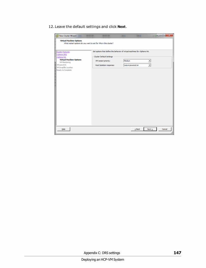
12.Leave the default settings and click Next.
Appendix C: DRS settings 147
Deploying an HCP-VM System
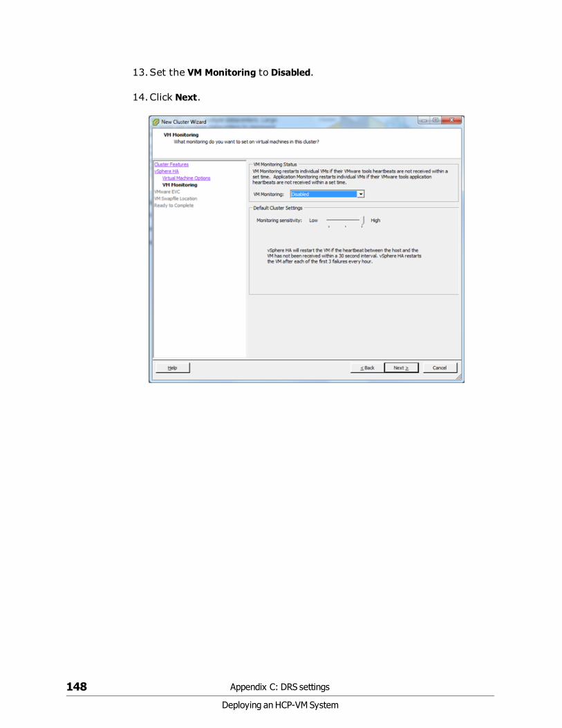
13.Set the VM Monitoring to Disabled.
14.Click Next.
148 Appendix C: DRS settings
Deploying an HCP-VM System

15.Select Disable EVC.
16.Click Next.
Appendix C: DRS settings 149
Deploying an HCP-VM System

17.Select where you prefer to store your Swapfile location.
18.Click Next.
150 Appendix C: DRS settings
Deploying an HCP-VM System

19.Review your settings.
20.Click Finish.
Appendix C: DRS settings 151
Deploying an HCP-VM System

21.In the left side navigation bar, select a Cluster and right click it. Thenclick on Edit Settings.
22.On the left side navigation bar of the Settings window, click on DRSGroups Manager.
23. In the DRS Groups Manager , create a group and add the VirtualMachines that you would like to keep on a specific server.
24.Create one Virtual Machine DRS Group for each Host.
25.Click Add in the Host DRS Groups section and place one host from thecluster in each group.
26.Click Next.
152 Appendix C: DRS settings
Deploying an HCP-VM System

27.On the left side navigation bar of the Settings window, click on Rules.
28.Create a new Rule where each VM group is matched to a Host Group,and set the type of rule to be Virtual Machines to Hosts.
29.Select Should run on hosts in group.
30.Click OK.
Note: You will create a rule that lets VMs run on other hosts in the event ofa failure. We will also setup a rule to alert you if that failure occurs. If youselect 'Must Run on Hosts in Group' then HA will not bring the server up onanother in the cluster in the even of Host failure defeating the purpose ofHA.
Appendix C: DRS settings 153
Deploying an HCP-VM System

Now that you have created all the Rules your cluster settings should looksomething like this:
154 Appendix C: DRS settings
Deploying an HCP-VM System

Setting an alarm
To set an alarm:
1. Right click on the Cluster and hover your cursor over Alarm in thesubmenu. Then click Add Alarm.
2. In the Alarm Settings window, name your alarm and set the Monitor toVirtual Machines.
3. Select Monitor for specific event occurring on this object.
Appendix C: DRS settings 155
Deploying an HCP-VM System

4. Go to the Triggers tab and select VM is violating a DRS VM-Host affinityrule.
5. Set the status to either warning or alert depending on how severe youthink it should be.
156 Appendix C: DRS settings
Deploying an HCP-VM System

6. Under the Trigger Conditions select an Argument of VM name.
7. Set the Value equal to each VM you want to monitor.
8. Add one argument for each VM.
Appendix C: DRS settings 157
Deploying an HCP-VM System

9. Set the Actions you want the system to take.
The image below shows either an email or SNMP trap, and what to do whenit goes from Green to Warning or Warning to Alert. Since you selected Alertearlier you can set how often the alert repeats in Frequency.
158 Appendix C: DRS settings
Deploying an HCP-VM System

Glossary
Aaccess control list (ACL)
Optional metadata consisting of a set of grants of permissions toperform various operations on an object. Permissions can be granted toindividual users or to groups of users.
ACLs are provided by users or applications and are specified as eitherXML or JSON.
ACL
See "access control list (ACL)" above.
active directory
A Microsoft product that, among other features, provides userauthentication services.
AD
See "active directory" above.
alert
A graphic that indicates the status of some particular element of an HCPsystem in the System Management Console.
Ccapacity
The total amount of primary storage space in HCP, excluding the spacerequired for system overhead for all data to be stored in primary runningstorage and primary spindown storage, including the fixed-content data,
159
Deploying an HCP-VM System
metadata, any redundant data required to satisfy services plans, andthe metadata query engine index.
CIFS
Common Internet File System. One of the namespace access protocolssupported by HCP. CIFS lets Windows clients access files on a remotecomputer as if the files were part of the local file system.
custom metadata
User-supplied information about an HCP object. Custom metadata isspecified as one or more annotations, where each annotation is adiscrete unit of information about the object. Users and applications canuse custom metadata to understand repurpose object content.
Ddatabase
An internal component of an HCP-VM system that contains essentialdata about the system, users, and user's files. The database ismaintained by one node and copied to the other.
data center
In VMware vSphere, a logical unit for grouping and managing hosts.
data protection level (DPL)
The number of copies of the data for an object HCP must maintain in therepository. The DPL for an object is determined by the service plan thatapplies to the namespace containing the object.
datastore
A representation of a location in which a virtual machine stores files. Adatastore can represent a location on a host or an external storagelocation such as a SAN LUN.
domain
A group of computers and devices on a network that are administered asa unit.
domain name system
A network service that resolves domain names into IP addresses forclient access.
160
Deploying an HCP-VM System

DNS
See "domain name system" on the previous page.
DPL
See "data protection level (DPL)" on the previous page.
EESXi
See "VMware ESXi" on page 169.
HHitachi Content Platform (HCP)
A distributed object-based storage system designed to support large,growing repositories of fixed-content data. HCP provides a singlescalable environment that can be used for archiving, businesscontinuity, content depots, disaster recovery, e-discovery, and otherservices. With its support for multitenancy, HCP securely segregatesdata among various constituents in a shared infrastructure. Clients canuse a variety of industry-standard protocols and various HCP-specificinterfaces to access and manipulate objects in an HCP repository.
HCP VM system
An HCP VM in which the nodes are virtual machines running in a VMwarevSphere environment.
HDDS
See "hitachi data discovery suite (HDDS)" below
hitachi data discovery suite (HDDS)
A Hitachi product that enables federated searches across multiple HCPsystems and other supported systems.
host
A physical computer on which virtual machines are installed and run.
161
Deploying an HCP-VM System

Llogical unit number (LUN)
A number used to identify a logical unit, which is a device addressed bythe Fibre Channel.
logical volume
A logical unit of storage that maps to the physical storage managed by anode. Logical volumes can be local or external.
LUN
See "logical unit number (LUN)" above.
Mmetadata
System-generated and user-supplied information about an object.Metadata is stored as an integral part of the object it describes, therebymaking the object self-describing.
multipathing
In SAIN systems, multiple means of access to a logical volume from asingle node.
Nnamespace
A logical partition of the objects stored in an HCP system. A namespaceconsists of a grouping of objects such that the objects in one namespaceare not visible in any other namespace. Namespaces are configuredindependently of each other and, therefore, can have differentproperties.
network
In an HCP system that supports virtual networking, a named networkconfiguration that identifies a unique subnet and specifies IP addressesfor none, some, or all of the nodes in the system.
162
Deploying an HCP-VM System

network file system
One of the namespace access protocols HCP supports for backing up andrestoring objects in the default namespace.
network interface controller (NIC)
A hardware interface that connects the computer to its appropriatenetwork. NICs can be physical (pNIC) or virtual (vNIC).
NFS
See "network file system" above.
NIC
See "network interface controller (NIC)" above.
node
A server or virtual machine running HCP-VM software. Two nodes arenetworked together to form an HCP-VM system.
Oobject
An exact digital representation of data as it existed before it wasingested into HCP, together with the system and custom metadata thatdescribes that data. Objects can also include ACLs that give users andgroups permission to perform certain operations on the object.
An object is handled as a single unit by all transactions and services,including shredding, indexing, versioning, and replication.
open virtualization format (OVF)
Standard file style for packaging and distributing virtual software.
OVF
See "open virtualization format (OVF)" above.
Pping
A utility that tests whether an IP address is accessible on the network byrequesting a response from it. Also, to use the ping utility.
163
Deploying an HCP-VM System

pNIC
See "network interface controller (NIC)" on the previous page.
Qquery
A request submitted to HCP to return metadata for objects that satisfy aspecified set of criteria. Also, to submit such a request.
RRAIN
See "redundant array of independant nodes (RAIN)" below.
redundant array of independant nodes (RAIN)
An HCP system configuration in which the nodes use internal or direct-attached storage.
replication
The process of keeping selected HCP tenants and namespaces andselected default-namespace directories in two HCP systems in sync witheach other. Basically, this entails copying object creations, delections,and metadata chages from each system to the other or from one systemto the other. HCP also replicates tenant and namespace configuration,tenant-level user and group accounts, retention classes, content classes,all compliance log messages, and all HCP tenant log messages.
repository
The aggregate of the namespaces defined for an HCP system.
running storage
Storage on continuously spinning disks.
SSAIN
See "SAN-attached array of independent nodes (SAIN)" on thefacing page.
164
Deploying an HCP-VM System

SAN-attached array of independent nodes (SAIN)
An HCP system configuration in which the nodes use SAN-attachedstorage.
search console
The web application that provides interactive access to HCP searchfunctionality. When the Search console uses the hcp metadata queryengine for search functionality, it is called the Metadata Query EngineConsole.
search facility
An interface between the HCP Search console and the searchfunctionality provided by the metadata query engine or HDDS. Only onesearch facility can be selected for use with the Search Console at anygiven time.
secure shell
A network protocol that lets you log into and execute commands in aremote computer. SSH uses encrypted keys for computer and userauthentication.
secure sockets layer
Secure Sockets Layer. A key-based Internet protocol for transmittingdocuments through an encrypted link.
service
A background process that performs a specific function that contributesto the continuous tuning of the HCP system. In particular, services areresponsible for optimizing the use of system resources and maintainingthe integrity and availability of the data stored in the HCP repository.
service plan
A named specification of an HCP service behavior that determines howHCP manages objects in a namespace. Service plans enable you to tailorservice activity to specific namespace usage patterns or properties.
simple network management protocol (SNMP)
A protocol HCP uses to facilitate monitoring and management of thesystem through an external interface.
165
Deploying an HCP-VM System

SNMP
See "simple network management protocol (SNMP)" on the previouspage.
SNMP trap
A type of event for which each occurrence causes SNMP to sendnotification to specified IP addresses. SNMP traps are set inmanagement information base (MIB) files.
spindown storage
Storage on disks that can be spun down and spun up as needed.
SSH
See "secure shell" on the previous page.
SSL
See "secure sockets layer" on the previous page.
SSL server certificate
A file containing cryptographic keys and signatures. When used with theHTTP protocol, an SSL server certificate helps verify that the web siteholding the certificate is authentic. An SSL server certificate also helpsprotect data sent to or from that site.
storage node
An HCP node that manages the objects that are added to HCP and canbe used for object storage. Each storage node runs the complete HCPsoftware.
subdomain
A subset of the computers and devices in a domain.
switch
A device used on a computer network to connect devices together.
syslog
A protocol used for forwarding log messages in an IP network. HCP usessyslog to facilitate system monitoring through an external interface.
166
Deploying an HCP-VM System

system management console
The system-specific web application that lets you monitor and manageHCP.
Ttag
An arbitrary text string associated with an HCP tenant. Tags can be usedto group tenants and to filter tenants lists.
tagged network
A network that has a VLAN ID.
tenant
An administrative entity created for the purpose of owning andmanaging namespaces. Tenants typically correspond to customers orbusiness units.
tenant management console
The tenant-specific web application that lets you monitor and managetenants and namespaces.
transaction log
A record of all create, delete, purge, and disposition operationsperformed on objects in any namespace over a configurable length oftime ending with the current time. Each operation is represented by anoperation record.
Uunix
Any UNIX-like operating system (such as UNIX itself or Linux).
upstream DNS server
A DNS server to which HCP routes the outbound communications itinitiates (for example, for sending log messages to syslog servers or forcommunicating with Active Directory).
167
Deploying an HCP-VM System

user account
A set of credentials that gives a user access to one or more of theSystem Management Console, the Tenant Management Console, theHCP management API, the HCP Search Console, namespace contentthrough the namespace access protocols, the metadata query API, andHCP Data Migrator.
user authentication
The process of checking that the combination of a specified usernameand password is valid when a user tries to log into the SystemManagement Console, the Tenant Management Console through themanagement API, or to access a namespace.
VvCenter
See "VMware vCenter Server" on the facing page.
versioning
An optional namespace feature that enables the creation andmanagement of multiple versions of an object.
virtual local area network (VLAN)
A distinct broadcast domain that includes devices within differentsegments of a physical network.
virtual machine
A piece of software that emulates the functionality of a physicalcomputer.
VLAN
See Virtual Local Area Network (VLAN).
VLAN ID
An identifier that's attached to each packet routed to HCP over aparticular network. This function is performed by the switches in thephysical network.
168
Deploying an HCP-VM System

vmNIC
A representation in VMware vSphere of one of the physical NICs on ahost.
VMware ESXi
The underlying operating system for the VMware vSphere product.
VMware vCenter Server
A VMware product that allows you to manage multiple ESXi hosts andthe virtual machines that they run.
vNIC
See "network interface controller (NIC)" on page 163.
Zzero-copy failover
The process of one node automatically taking over management ofstorage previously managed by another node that has becomeunavailable.
169
Deploying an HCP-VM System

170
Deploying an HCP-VM System

.
.zip 69
BBack-end network 5, 135Back-end Network 59
CCluster 19Compute 2
Ddata center 18Datastores 38diagnostic 123DRS 143
EESXi 27Evaluation 7
FFailover 7, 124Fibre Channel Connectivity 34Front-end network 5, 137Front-end Network 53
HHCP 1HCP-VM 1, 7HCP-VM network 97HCP-VM nodes 133HCP system 107HDDS 7Heartbeat 50HiTrack 6
HNAS 48, 52
IIPMI 121
Llogical volumes 125LUN 3
MMetadata 1multi-cast 5
NNamespaces 1Network Time Protocol 15NFS 48NFS datastore 49nodes 103NTP 15
OOVF 69, 81, 139
PpNIC 5-6PVSCSI 3
RRAID6 2RDM 3, 81Repository 1
SSAR 122SNMP 122
Index
Index 171
Deploying an HCP-VM System

switching
switching 53, 135, 137Switching 59System management console 121
VVMDK 3, 69, 141VMFS 3vmNICs 5Vmware 1, 9vNIC 5vSphere 1vSphere HA cluster 7, 18
172 Index
Deploying an HCP-VM System

Deploying an HCP-VM System

MK-92ARC040-02
Hitachi Data Systems
Corporate Headquarters2845 Lafayette StreetSanta Clara, California 95050-2627U.S.A.www.hds.com
Regional Contact Information
Americas+1 408 970 [email protected]
Europe, Middle East, and Africa+44 (0) 1753 [email protected]
Asia Pacific+852 3189 [email protected]


