Embed Size (px)
Citation preview

This is an uncontrolled copy when printed.
Title: High-Voltage Electrical Work
Standard No.: B4
Effective Date: 03/30/2015
Releasability: There are no releasability restrictions on this publication.
The provisions and requirements of this standard are mandatory for use by all personnel engaged in work tasks
necessary to fulfill the AEDC mission. Please contact your safety, industrial health and/or environmental
representative for clarification or questions regarding this standard.
Approved:
Contractor ATA Director
Safety, Health, and Environmental
Air Force Functional Chief
Department of the Air Force
HQ AEDC (AFMC)
Arnold AFB, TN 37389
Safety, Health, and Environmental Standard

Safety, Health and Environmental Standard B4
This is an uncontrolled copy when printed.
Record of Review/Revision
Date/POC Description
03/24/15
Northcott; Tate
Updated to align with the 2015 NFPA 70E Standard for Electrical Safety in the Workplace.
07/16/14
Tate; Northcott
Administrative update to incorporate current arc flash labels.
02/07/13
R. Tate
T. Northcott
Three-year review: Clarified a number of sections and restructured to align with SHE Standard
B4 Low-Voltage Electrical Safety-Related Work Practices where appropriate. Added limited
approach distances for direct current; modified EEWP approval block (Annex A); added
nomenclature to Annex D throughout. Deleted obsolete annexes and renumbered remaining
annexes. Added attachments for Electrical Operational and Electrical Maintenance work flow
charts. Added NFAC Supplement. [03/11/2013: Incorporated Base Operating Contractor
Process Council administrative changes; 03/21/2013: Incorporated Base Operating Contractor
Executive Management Steering Committee Changes.]
08/29/11
R.Eichel
T. Wiley
T. Northcott
Updated throughout for consistency of terminology with SHE Standard B6 Low Voltage
Electrical Work; provided separate Energized Electrical Work Permit for high voltage operations.
Clarified when a hold order is required. Defined Power System Dispatcher, Hold Order Issuer
(Plant) and Assignee. Added requirement for Directors to appoint hold order issuers in writing
annually and to forward list to Electrical Operations. Combined definition of supervisor and craft
supervisor. Deleted references to emergency services. Updated High Voltage Hold Order Annex
with Plant hold order issuer information; added examples and noted ability of multiple work
groups to work under same hold order.
03/25/09
S. Bryan and
ESS
Revised to incorporate September 2008 NFPA 70E requirements throughout. These requirements
became available in December 2008. Revisions made in coordination with the Electrical Systems
Subcommittee (ESS).
11/05/07
S. Bryan
Annual review: Minor revision to clarify NFPA 70E requirements for arc flash clothing for work
on Hazard Risk Class 0 – long-sleeved shirts are required.
11/09/06
T. Lavelle
Major revision: Read entire standard
1/6/05
R. Jones
General revision, reorganization and incorporation of site comments.
03/05/04
G. Neal
Clarified PPE requirements; reformatted Annexes and tables.
01/15/04 Initial Safety Standard Issued.

This is an uncontrolled copy when printed.
HIGH-VOLTAGE ELECTRICAL WORK
1.0 INTRODUCTION/SCOPE/APPLICABILITY
1.1 Introduction – This standard outlines the hazards involved, safety equipment required, safety precautions to be
observed, and operating procedure requirements when working with high voltage electricity, i.e., any voltage
greater than 600 volts. Any time a high voltage supply is locked out to provide personnel protection a hold
order shall be required.
EXCEPTION: Linemen working under a caution order are exempt from the hold order requirement.
1.2 Scope – This standard applies in all situations where exposure to energized or potentially energized electrical
equipment is possible due to the nature of the work to be performed. Following this standard will help ensure
that electrical work is performed under the safest conditions possible.
This standard addresses safety of workers whose job responsibilities entail interaction with electrical equipment
and systems with potential exposure to energized electrical equipment and circuit parts. Concepts in this standard
are often adapted to other workers whose exposure to electrical hazards is unintentional or not recognized as part
of their job responsibilities. The highest risk for injury from electrical hazards for other workers involve
unintentional contact with overhead power lines and electric shock from machines, tools, and appliances.
1.3 Applicability – This standard applies to all employees and subcontractors engaged in operations, maintenance,
or construction at AEDC.
2.0 BASIC HAZARDS/HUMAN FACTORS
2.1 Shock Hazard – A dangerous condition associated with the possible release of energy caused by contact or
approach to energized electrical conductors or circuit parts. Electric shock is the most common hazard to be
encountered in electrical operations. This is caused when a person comes in contact with an energized part, and
electrical current travels through the body. Minor shock may cause tingling or discomfort. A serious shock
may cause extreme pain, burns, and/or death. Although the shock may not be severe enough to stop breathing,
it may cause a fall or other accident. If a worker sustains a severe shock that does stop the heart and/or
breathing, cardio-pulmonary resuscitation (CPR) should be administered by a properly trained individual
immediately and medical aid should be summoned.
CAUTION: Workers shall exercise extreme caution to avoid contact with a “hot” line or bus bar.
2.3 Arc Flash Hazard – A dangerous condition associated with the release of energy caused by an electric arc.
This flash can damage a person’s eyes, cause burns up to 3rd
degree, and/or death. This hazard exists when
energized electrical conductors or circuit parts are exposed or within guarded or enclosed equipment, provided
a person is interacting with the equipment in such a manner that could cause an electric arc.
Arcing can also cause overheating to the extent molten metal may be expelled which may result in the worker
being burned. Vaporized metal and ionized gases, as well as metallic fragments, may be violently thrust into the
zone occupied by the worker, necessitating use of arc-rated (AR) personal protective equipment (PPE).
2.4 Arc blast – An explosive force caused by the rapid expansion of super-heated air and metal vaporized during
an electric arc. Arc blasts can damage a person’s hearing or cause other internal injuries. Shrapnel from the
blast may pierce the skin. Blasts from higher energies may cause death.
2.5 Fire – Improper wiring, circuit overloading, and defective tools or equipment can cause sparking, or overheat
wires. This could cause a fire and damage property, or injure personnel.
3.0 DEFINITIONS
Automated External Defibrillator (AED) – A device used to administer an electric shock through the chest wall to
treat ventricular fibrillation.
Arc Flash Protection Boundary – When an arc flash hazard exists, an approach limit at a distance from a prospective
arc source within which a person could receive a second degree burn if an electrical arc flash were to occur.
Barricade – Physical obstruction such as tapes, cones, or wood or metal structures intended to provide a warning and
to limit access to a hazardous area.
Department of the Air Force
HQ AEDC (AFMC)
Arnold AFB, TN 37389
HQ AEDC (AFMC)
Arnold-1806
Effective Std. No.
03/30/15 B4
Safety, Health, and Environmental Standard

SHE Standard B4, High-Voltage Electrical Work Page 2 of 22
This is an uncontrolled copy when printed.
Barrier – Physical obstruction which is intended to prevent contact with energized lines or equipment or to prevent
unauthorized access to a work area.
Base Operating Contractor – A long-term contractor directly accountable to the Air Force for the AEDC mission;
term used to identify the AEDC Operation, Maintenance, Information Management and Support Contractor.
Bond – The electrical interconnection of conductive parts designed to maintain a common electrical potential.
Bus – A conductor or a group of conductors that serve as a common connection for two or more circuits.
Cable – A conductor with insulation (single-conductor cable), or a combination of conductors insulated from one
another (multiple-conductor cable).
Cardiopulmonary Resuscitation (CPR) – An emergency medical procedure, which includes opening and maintaining
an airway, providing ventilation through rescue breathing, and providing artificial circulation through the use of
external cardiac compression.
Caution Order – Formal procedure for keeping a high voltage circuit or line from being automatically re-energized.
Circuit – A conductor or system of conductors through which an electric current is intended to flow.
Clearance (between objects) – Clear distance between two objects measured surface to surface.
Competent Person – A individual capable of identifying existing or predictable hazards in the surroundings of
working conditions which are hazardous or dangerous to employees, and who has authorization to take prompt
corrective measures to eliminate them.
Conductor – A material, usually in the form of a wire, cable, or bus bar, used for carrying an electric current.
Craft Supervisor – Supervisor responsible for the safety of work crews performing maintenance or servicing of
equipment or systems; this may also be the person normally designated by management to implement high voltage
hold order procedures in their area of responsibility.
Current-Carrying Part – A conducting part intended to be connected in an electric circuit to a source of voltage.
Non-current-carrying parts are those parts which are not intended to be so connected.
De-energized – Free from any electrical connection to a source of potential difference and from electrical charge: not
having a potential different from earth. De-energized alone does not constitute an electrically safe work condition.
Diagnostic Work – A category of work that involves the taking readings or measurements of electrical equipment,
with approved test equipment which does not require making any physical change to the equipment. In most cases,
diagnostic work requires shock PPE and/or arc flash PPE along with other required industrial PPE.
Electric Equipment – A general term including material, fittings, devices, appliances, fixtures, apparatus, and the
like used as part of or in connection with an electrical installation.
Electrical Equipment – Wiring, circuits, switches, switchgear, fuses, breakers, distribution systems, and any other
equipment or systems capable of containing electrical energy.
Electrical Standby Person – An employee trained in energized electrical procedures, emergency rescue techniques
for electric shock victims, cardiopulmonary resuscitation (CPR), first aid, and confined space procedures, as
warranted by the job situation.
Electrical Supply Lines – Outdoor overhead conductors supported on a pole or other structure and used to transmit
electric energy.
Electrically Safe Work Condition – A state in which the conductors, circuits, and equipment to be worked on has
been disconnected or isolated from energized parts, locked/tagged in accordance with established lockout/tagout
practices [as detailed in AEDC SHE Standard B2, Lockout/Tagout (LOTO)], tested to ensure the absence of voltage.
(Flowcharts for achieving electrical safe work conditions for Electrical Maintenance and Electrical Operations are
provided in Attachments 1 and 2.)
Energized – Electrically connected to, or is, a source of voltage. Any electrical circuit or circuit part that has not
been disconnected, LOTO, absence of voltage properly verified, and grounded shall be considered energized.
Energized Electrical Work Permit (EEWP) – A permit approved by supervision or management which authorizes
work to be performed within the limited approach boundary of energized circuits or circuit parts operating at 50
volts or more. The purpose of the permit is to ensure that the increased risks posed by this work receive adequate
consideration before the work is performed (Permit Form Annex A of this Document).
Energy Source – Any electrical, mechanical, hydraulic, pneumatic, chemical, nuclear, thermal, or other energy
source that could cause injury to personnel.

SHE Standard B4, High-Voltage Electrical Work Page 3 of 22
This is an uncontrolled copy when printed.
Exposed (as applied to live parts) – Capable of being inadvertently touched or approached nearer than a safe
distance by a person. It is applied to parts that are not suitably guarded, isolated or insulated.
Exposure – Where hazards are present or could be created that might result in harm to personnel, equipment or the
environment if not properly controlled.
Ground – A conducting connection, whether intentional or accidental, between an electric circuit or equipment and
the earth, or to some conducting body that serves in place of the earth.
Grounded – Connected to earth or to some conducting body that serves in place of the earth.
Guarded – Covered, fenced, enclosed, or otherwise protected, by means of suitable covers or casings, barrier rails or
screens, mats, or platforms, designed to minimize the possibility, under normal conditions, of dangerous approach or
accidental contact by persons or objects.
NOTE: Wires which are insulated, but not otherwise protected, are not considered to be guarded.
Hazardous Work – Work involving exposure to energized electrical parts.
High-Voltage Hold Order – A formal procedure for isolating high-voltage equipment from any source of electric
potential. Hold orders require the use of Form GC-631, Electrical Hold Order. See Annex B.
Hold Order Assignee – An electrically qualified person, trained in the hold order process and who has been
designated by management to be issued hold orders. This person is responsible for determining that all necessary
safeguards have been taken before permitting maintenance work or inspection of electrical equipment or circuits
covered by the hold order.
Hold Order Issuer, Plant – A person who is technically qualified, through experience and or training, to determine
necessary points of protection on a system for a specified configuration and who is designated in writing by
management to perform the duties.
Insulated – Separated from other conducting surfaces by a dielectric (including air space) offering a high resistance
to the passage of current.
Insulation – That which is relied upon to insulate the conductor from other conductors or conducting parts or from ground.
Job Safety Analysis (JSA) – (Also known as a safe plan of action or similar name.) A document prepared to help
workers and management review hazards and safety precautions required for each job. (AEDC uses Form GC-1707
Job Safety Analysis; see SHE Standard A10, Job Safety Analysis for details.)
Job Safety Review (JSR) – A streamlined safety analysis technique for routine jobs meeting the following criteria:
1. The job is routine (At least one assigned person has experience on the job)
2. The job must be able to be completed in three days or less, and a new JSR must be initiated each day.
3. Three persons or less are assigned to the job.
(AEDC uses Form GC-1862 Job Safety Review; see SHE Standard A10, Job Safety Analysis for details.)
Limited Approach Boundary – An approach limit at a distance from an exposed energized electrical conductor or
circuit part within which a shock hazard exists. Non-electrically qualified personnel may not cross this boundary
unless escorted by a qualified electrical person.
Line Truck – A specialty vehicle designed for electrical supply line work, that includes a boom with a power take
off for an auger or set of jaws for setting power poles.
Minimum Approach Distance – The closest distance a qualified employee is permitted to approach either an
energized or a grounded object, as applicable for the work method being used.
Outside Contractor/Subcontractor - An organization employed by a contractor or the Air Force to do construction,
maintenance, repair or other work at AEDC. There is no employment relationship, control or supervision of the
subcontractor's employees by AEDC contractors. Also referred to as the construction contractor.
Personal Protective Equipment (PPE) – Equipment such as voltage-rated rubber gloves, hard hats, face shields,
protective arc-flash clothing, hoods, etc. used to protect the worker from electrical shock and arc-flash hazards. (See
SHE Standard F2 for additional information.)
Potentially Energized – Electrical equipment or circuits capable of containing electrical energy that has not been
locked out, tagged out, and verified as de-energized by proper testing methods.
Power System Dispatcher – An electrically qualified person who, in accordance with the power agreement between
AEDC and TVA, has the responsibility for the safe operation of the electrical power distribution system at AEDC.
This person controls loads on feeders within specified limitations, directs all switching operations when it becomes
necessary to make configuration changes to the power distribution system, keeps all required logs and forms for
SHE Standard B4, High-Voltage Electrical Work Page 4 of 22
This is an uncontrolled copy when printed.
permanent retention, provides clearances and issues and tracks all Hold Orders Numbers. He directs all activities of
the Power Switchboard Operator for safe and efficient operation of the high voltage distribution equipment.
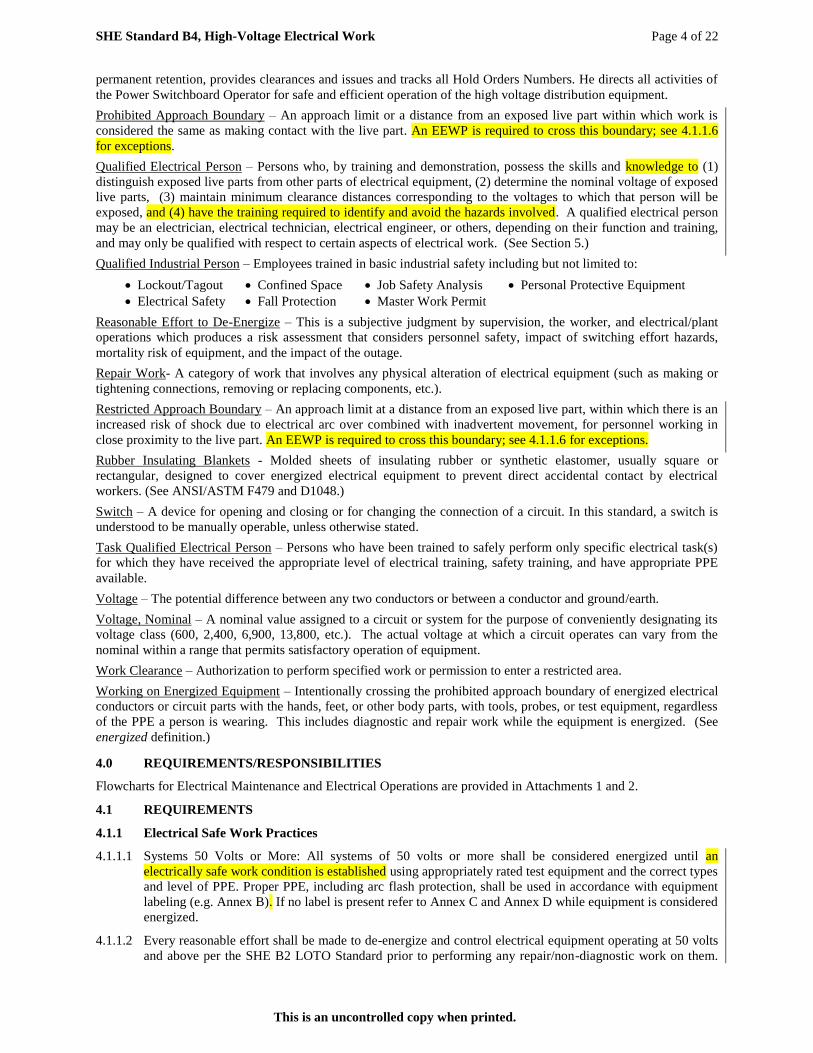
Prohibited Approach Boundary – An approach limit or a distance from an exposed live part within which work is
considered the same as making contact with the live part. An EEWP is required to cross this boundary; see 4.1.1.6
for exceptions.
Qualified Electrical Person – Persons who, by training and demonstration, possess the skills and knowledge to (1)
distinguish exposed live parts from other parts of electrical equipment, (2) determine the nominal voltage of exposed
live parts, (3) maintain minimum clearance distances corresponding to the voltages to which that person will be
exposed, and (4) have the training required to identify and avoid the hazards involved. A qualified electrical person
may be an electrician, electrical technician, electrical engineer, or others, depending on their function and training,
and may only be qualified with respect to certain aspects of electrical work. (See Section 5.)
Qualified Industrial Person – Employees trained in basic industrial safety including but not limited to:
Lockout/Tagout Confined Space Job Safety Analysis Personal Protective Equipment
Electrical Safety Fall Protection Master Work Permit
Reasonable Effort to De-Energize – This is a subjective judgment by supervision, the worker, and electrical/plant
operations which produces a risk assessment that considers personnel safety, impact of switching effort hazards,
mortality risk of equipment, and the impact of the outage.
Repair Work- A category of work that involves any physical alteration of electrical equipment (such as making or
tightening connections, removing or replacing components, etc.).
Restricted Approach Boundary – An approach limit at a distance from an exposed live part, within which there is an
increased risk of shock due to electrical arc over combined with inadvertent movement, for personnel working in
close proximity to the live part. An EEWP is required to cross this boundary; see 4.1.1.6 for exceptions.
Rubber Insulating Blankets - Molded sheets of insulating rubber or synthetic elastomer, usually square or
rectangular, designed to cover energized electrical equipment to prevent direct accidental contact by electrical
workers. (See ANSI/ASTM F479 and D1048.)
Switch – A device for opening and closing or for changing the connection of a circuit. In this standard, a switch is
understood to be manually operable, unless otherwise stated.
Task Qualified Electrical Person – Persons who have been trained to safely perform only specific electrical task(s)
for which they have received the appropriate level of electrical training, safety training, and have appropriate PPE
available.
Voltage – The potential difference between any two conductors or between a conductor and ground/earth.
Voltage, Nominal – A nominal value assigned to a circuit or system for the purpose of conveniently designating its
voltage class (600, 2,400, 6,900, 13,800, etc.). The actual voltage at which a circuit operates can vary from the
nominal within a range that permits satisfactory operation of equipment.
Work Clearance – Authorization to perform specified work or permission to enter a restricted area.
Working on Energized Equipment – Intentionally crossing the prohibited approach boundary of energized electrical
conductors or circuit parts with the hands, feet, or other body parts, with tools, probes, or test equipment, regardless
of the PPE a person is wearing. This includes diagnostic and repair work while the equipment is energized. (See
energized definition.)
4.0 REQUIREMENTS/RESPONSIBILITIES
Flowcharts for Electrical Maintenance and Electrical Operations are provided in Attachments 1 and 2.
4.1 REQUIREMENTS
4.1.1 Electrical Safe Work Practices
4.1.1.1 Systems 50 Volts or More: All systems of 50 volts or more shall be considered energized until an
electrically safe work condition is established using appropriately rated test equipment and the correct types
and level of PPE. Proper PPE, including arc flash protection, shall be used in accordance with equipment
labeling (e.g. Annex B). If no label is present refer to Annex C and Annex D while equipment is considered
energized.
4.1.1.2 Every reasonable effort shall be made to de-energize and control electrical equipment operating at 50 volts
and above per the SHE B2 LOTO Standard prior to performing any repair/non-diagnostic work on them.

SHE Standard B4, High-Voltage Electrical Work Page 5 of 22
This is an uncontrolled copy when printed.
Energized work shall be permitted only where it can be demonstrated that the task to be performed is
infeasible in a de-energized state due to equipment design or operational limitations.
4.1.1.3 Electrical circuits shall be confirmed de-energized prior to performing Repair Work on them unless an
EEWP has been completed. All circuits shall be considered energized until proven to be de-energized using
appropriate test equipment (Section 4.1.2) and grounded if necessary (Section 4.1.3).
4.1.1.4 Equipment with Arc Flash Incident Energies above 40 cal/cm2
shall be de-energized before any work or
local alteration (e. g., breaker operation or racking) may be performed.
4.1.1.5 Energized electrical equipment with Arc Flash Incident Energies of 40 cal/cm² or less can be
worked/operated only when approval is granted with proper documentation (JSA and EEWP, when
required) and all required PPE is worn.
4.1.1.5.1 The correct types and level of PPE is mandatory when performing either repair-type or diagnostic-type
work on energized electrical equipment or locally altering the configuration/position of energized
electrical equipment, e.g. operating breakers, switches, disconnects; racking breakers, etc. If equipment
is not labeled in accordance with Annex C, refer to Annex D, and Annex E or NFPA 70E 2015 Edition.
4.1.1.5.2 Energized conductors/components may be covered and or guarded by blankets, mats, etc., to protect from
accidental contact by the qualified worker when within the Limited Approach Boundary. If the
covered/guarded conductors/components can no longer be inadvertently contacted, then the shock hazard
and arc flash hazard associated with those conductors/components no longer exist.
4.1.1.6 Energized Electrical Work Permit (EEWP): The EEWP is required when working within the restricted
approach boundary or the arc flash boundary of exposed energized electrical conductors or circuit parts that
are not placed in an electrically safe work condition.
NOTE: The purpose of the EEWP is to ensure that the increased risks posed by this work receive adequate
consideration to ensure that it is infeasible to perform the task with the circuit de-energized (Permit Form
Annex A of this document).
4.1.1.6.1 Department Director or Deputy Director Approval shall be required before any repair-type work is
performed within the prohibited approach boundary of energized electrical equipment operating at greater
than 150V (AC or DC) nominal. Documentation is required on the EEWP.
4.1.1.6.2 The EEWP shall not be approved when the Arc Flash Incident is greater than 40 cal/cm².
4.1.1.6.3 The following routine operations do not require an approved EEWP, but does require Manager or
Supervisor approval, which is indicated by signing the JSA/JSR. Craft cannot provide this approval.
4.1.1.6.3.1 Diagnostic testing, de-energizing or re-energizing an electrical system
4.1.1.6.3.2 Switching, operating disconnects, racking breakers
4.1.1.6.3.3 Operating electrical circuit testing or diagnostic equipment.
4.1.1.6.3.4 Re-lamping by personnel other than a qualified electrical person, no approval is required for a qualified
electrical person.
4.1.1.6.3.5 Removal/insertion of a DC Fuse Block rated less than 151VDC nominal.
4.1.1.7 Only a qualified electrical person shall be permitted to work on energized electrical equipment or within
the Restricted Approach Boundary of energized circuits or circuit parts.
4.1.1.7.1 Only a qualified electrical person shall energize or de-energize any disconnect over 50 volts where the
operation could directly or potentially expose personnel to energized electrical circuits. Personnel may
be task qualified to safely operate electrical equipment rated over 50 volts provided they are equipped
with the required Arc Flash PPE and trained to identify and avoid the hazards involved with the task.
4.1.1.7.2 A minimum of two qualified electrical persons shall be assigned to any work where the potential exists for
direct contact with energized circuits greater than 300 volts nominal or when there is an elevated potential for
arc flash such as racking a breaker off of an energized bus. As a minimum, the second qualified electrical
person shall be dressed in the same required PPE as the qualified electrical person performing the task.
4.1.1.8 A JSA/JSR shall be completed for all electrical work, energized or de-energized.

SHE Standard B4, High-Voltage Electrical Work Page 6 of 22
This is an uncontrolled copy when printed.
4.1.1.9 The approach boundaries to live (energized) parts for shock protection are tabulated below. Qualified
electrical persons shall provide boundaries to prevent unqualified personnel from getting any closer to
exposed energized parts than the Limited Approach Boundary as shown below:
Approach Boundaries for Alternating Current Systems
Nominal
Voltage
Limited Approach Boundary Restricted Approach
Boundary
Prohibited Approach
Boundary Exposed Movable
Conductor
Exposed Fixed
Circuit Part
600 to 750 10 ft. 0 in. 3 ft. 6 in. 1 ft. 0 in. 0 ft. 1 in.
751 to 15kV 10 ft. 0 in. 5 ft. 0 in. 2 ft. 2 in. 0 ft. 7 in.
15.1kV to 36kV 10 ft. 0 in. 6 ft. 0 in. 2 ft. 7 in. 0 ft. 10 in.
36.1kV to 46kV 10 ft. 0 in. 8 ft. 0 in. 2 ft. 9 in. 1 ft. 5 in.
46.1kV to 72.5kV 10 ft. 0 in. 8 ft. 0 in. 3 ft. 3 in. 2 ft. 2 in.
72.6kV to 121kV 10 ft. 8 in. 8 ft. 0 in. 3 ft. 4 in. 2 ft. 9 in.
138kV to 145kV 11 ft. 0 in. 10 ft. 0 in. 3 ft. 10 in. 3 ft. 4 in.
161kV to 169kV 11 ft. 8 in. 11 ft. 8 in. 4 ft. 3 in. 3 ft. 9 in.
Approach Boundaries for Direct Current Systems
Nominal Potential
Difference System
Voltage
Limited Approach Boundary Restricted
Approach
Boundary
Prohibited
Approach
Boundary Exposed Movable
Conductor
Exposed Fixed
Circuit Part
Less than 100 Not specified Not specified Not specified Not specified
100 to 300 10 ft. 0 in. 3 ft. 6 in. Avoid contact Avoid Contact
301 to 1kV 10 ft. 0 in. 3 ft. 6 in. 1 ft. 0 in. 0 ft. 1 in.
1.1 to 5kV 10 ft. 0 in. 5 ft. 0 in. 1 ft. 5 in. 0 ft. 4 in.
5 kV to 15 kV 10 ft. 0 in. 5 ft. 0 in. 2 ft. 2 in. 0 ft. 7 in.
15.1 kV to 45 kV 10 ft. 0 in. 8 ft. 0 in. 2 ft. 9 in. 1 ft. 5 in.
45.1 kV to 75 kV 10 ft. 0 in. 8 ft. 0 in. 3 ft. 2 in. 2 ft. 1 in.
75.1 kV to 150 kV 10 ft. 8 in. 10 ft. 0 in. 4 ft. 0 in. 3 ft. 2 in.
150.1 kV to 250 kV 11 ft. 8 in. 11 ft. 8 in 5 ft. 3 in. 5 ft. 0 in.
250.1 kV to 500 kV 20 ft 0 in. 20 ft 0 in. 11 ft. 6 in. 10 ft. 10 in.
500.1 kV to *00 kV 26 ft. 0 in. . 26 ft. 0 in. 16 ft. 5 in. 16 ft. 5 in.
NOTE: “Exposed movable conductor” describes a condition in which the distance between the conductor and a
person is not under the control of the person. The term is normally applied to overhead line conductors
supported by poles.
4.1.1.9.1 To cross the prohibited approach boundary (shock hazard), the qualified person shall:
(a) Have specified training to work on exposed live parts.
(b) Have a completed/approved JSA/JSR and EEWP when required.
(c) Use PPE suitable for working near exposed live parts and rated for the voltage and energy level
involved as described in Section 4.1.15.
(d) Employees shall use insulated tools or handling equipment, or both, when working inside the
prohibited approach boundary of exposed energized electrical conductors or circuit parts. Annex C
provides further information for tasks that require insulated and insulating hand tools.
4.1.1.9.2 To cross the restricted approach boundary (possible shock from arc over), the qualified person shall:
(a) Have a completed and approved JSA/JSR and EEWP when required.
(b) Use PPE suitable for working near exposed live parts and rated for the voltage and energy level
involved as described in Section 4.1.15.
(c) Be certain that no part of the body enters the prohibited space.
(d) Minimize the risk from unintended movement, by keeping as much of the body as possible out of the
restricted space; body parts in the restricted space must be protected.

SHE Standard B4, High-Voltage Electrical Work Page 7 of 22
This is an uncontrolled copy when printed.
(e) Employees shall use insulated tools or handling equipment, or both, when working inside the
restricted approach boundary of exposed energized electrical conductors or circuit parts. Annex C
provides further information for tasks that require insulated and insulating hand tools.
4.1.1.9.3 Limited Approach Boundary:
(a) Boundary is to be set up by the qualified electrical person. The type of boundary used will depend on
the area. In high traffic areas, physical barriers, like stanchions or red danger tape may be used. For
remote areas, visually monitoring the area may be appropriate. The distance of the barrier from the
exposed conductor will be the equal to or greater than the limited approach boundary or the arc flash
hazard boundary, whichever is greater. For more information, please see AEDC SHE Standard B3,
Control of Hazardous Areas.
(b) Have a completed/approved JSA/JSR.
(c) May only be crossed by non-electrical personnel when escorted by a qualified electrical person
familiar with the current work.
(d) Walls or other physical barriers within the boundary, which provide sufficient protection, will suffice
for the barrier, provided entrance is limited.
4.1.1.9.4 Arc Flash Protection Boundary: The distance for the flash hazard boundary will be found on the
equipment’s arc flash warning decal (see Annex B). For low-voltage equipment without a decal, the arc
flash protection boundary shall be in accordance with the value found in Annex C according to the
appropriate equipment type and task. Whenever any part of a person’s body or head is within the arc/flash
protection boundary, the person must:
4.1.1.9.4.1 Use appropriate PPE and protective equipment in accordance with the Arc Flash Label attached to the
equipment or as specified in Annex D of this standard.
4.1.1.9.4.2 Ensure all PPE is in good condition, is locally inspected prior to use, and has been externally inspected
within the required interval, if required.
4.1.1.9.4.3 Have a completed and approved JSA/JSR and EEWP when required.
4.1.1.10 Conductive articles of jewelry and clothing (such as watchbands, bracelets, rings, key chains, necklaces,
metallized aprons, cloth with conductive thread, metal headgear, or metal framed glasses) shall not be worn
when working within the Restricted Approach Boundary of energized or potentially energized circuits or
equipment. Qualified Electrical Persons requiring prescription glasses through the company furnished PPE
plan shall get plastic frames prescription safety glasses.
4.1.1.11 No current-carrying conductors shall be opened without the use of a properly rated switch in the circuit. Do
not cut cables or open connections without first verifying that there is no current flowing. This applies to
both maintenance and demolition work.
4.1.1.12 When performing demolition work, qualified electrical persons shall positively verify that the cables and
circuits are de-energized before cutting conduits, cable trays, supports, and associated wiring for removal.
4.1.1.13 No person shall authorize, perform, nor permit alterations or modifications to equipment, circuits, or
protective device settings without written authorization from the system engineer. This includes, but is not
limited to, switchgear modifications, removal or bypass of device contacts from control circuits, and the
installation of temporary back feeds.
4.1.1.13.1 Any setting changes on breakers or protective relays on 480V or greater systems shall be coordinated and
approved by the Power Control Power System Analysis Systems Engineer and/or the Power Control Arc
Flash Systems Engineer. Changing settings on a protective device will alter the arc flash ratings of the
downstream equipment and could put personnel at risk if the required level of PPE is not appropriately
documented on the equipment.
4.1.1.14 Employees shall use insulated tools and/or handling equipment when working inside the restricted
approach boundary of live parts. Insulated tools shall be protected from damage to the insulating material.
Insulated tools shall be rated for the voltages on which they are used. Insulated tools shall be designed and
constructed for the environment to which they will be exposed and the manner in which they are used.
4.1.1.15 Underground Electrical Lines and Equipment: Before excavation starts, Master Work Permit Section IV
must be approved to identify and mark the location of the electrical lines or equipment. When it has been
determined that a reasonable possibility of contacting energized electrical lines or equipment exists,
appropriate safe work practices and PPE shall be used during the excavation.
SHE Standard B4, High-Voltage Electrical Work Page 8 of 22
This is an uncontrolled copy when printed.
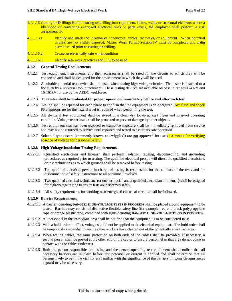
4.1.1.16 Cutting or Drilling: Before cutting or drilling into equipment, floors, walls, or structural elements where a
likelihood of contacting energized electrical lines or parts exists, the employee shall perform a risk
assessment to:
4.1.1.16.1 Identify and mark the location of conductors, cables, raceways, or equipment. When potential
circuits are not visibly exposed, Master Work Permit Section IV must be completed and a dig
permit issued prior to cutting or drilling.
4.1.1.16.2 Create an electrically safe work condition
4.1.1.16.3 Identify safe work practices and PPE to be used
4.1.2 General Testing Requirements
4.1.2.1 Test equipment, instruments, and their accessories shall be rated for the circuits to which they will be
connected and shall be designed for the environment in which they will be used.
4.1.2.2 A suitable potential test device shall be used when testing high-voltage circuits. The tester is fastened to a
hot stick by a universal tool attachment. These testing devices are available on base in ranges 1-40kV and
16-161kV for use by the AEDC workforce.
4.1.2.3 The tester shall be evaluated for proper operation immediately before and after each test.
4.1.2.4 Testing shall be repeated for each phase to confirm that the equipment is de-energized. Arc flash and shock
PPE appropriate for the hazard level is required when performing the test.
4.1.2.5 All electrical test equipment shall be stored in a clean dry location, kept clean and in good operating
condition. Voltage tester leads shall be protected to prevent damage by other objects.
4.1.2.6 Test equipment that has been exposed to excessive moisture shall be immediately removed from service
and may not be returned to service until repaired and tested to assure its safe operation.
4.1.2.7 Solenoid-type testers (commonly known as “wiggies”) are not approved for use as a means for verifying
absence of voltage for personnel safety.
4.1.2.8 High-Voltage Insulation Testing Requirements
4.1.2.8.1 Qualified electricians and linemen shall perform isolation, tagging, disconnecting, and grounding
procedures as required prior to testing. The qualified electrical person will direct the qualified electricians
or test technicians as to which grounds shall be removed before testing.
4.1.2.8.2 The qualified electrical person in charge of testing is responsible for the conduct of the tests and for
dissemination of safety instructions to all personnel involved.
4.1.2.8.3 Two qualified electrical technicians (or one technician and a qualified electrician or lineman) shall be assigned
for high-voltage testing to ensure tests are performed safely.
4.1.2.8.4 All safety requirements for working near energized electrical circuits shall be followed.
4.1.2.9 Barrier Requirements
4.1.2.9.1 A barrier, denoting DANGER: HIGH-VOLTAGE TESTS IN PROGRESS shall be placed around equipment to be
tested. Barriers may consist of distinctive flexible safety line (for example, red-and-black polypropylene
rope or orange plastic tape) combined with signs denoting DANGER: HIGH-VOLTAGE TESTS IN PROGRESS.
4.1.2.9.2 All personnel in the immediate area shall be notified that the equipment is to be considered HOT.
4.1.2.9.3 With a hold order in effect, voltage should not be applied to the electrical equipment. The hold order shall
be temporarily suspended to ensure other workers have cleared out of the potentially energized area.
4.1.2.9.4 When testing cables, the same protection on both ends of the cables shall be provided. If necessary, a
second person shall be posted at the other end of the cables to ensure personnel in that area do not come in
contact with the cables under test.
4.1.2.9.5 Both the person responsible for testing and the person operating test equipment shall confirm that all
necessary barriers are in place before test potential or current is applied and shall determine that all
persons likely to be in the vicinity are familiar with the significance of the barriers. In some circumstances
a guard may be necessary.
SHE Standard B4, High-Voltage Electrical Work Page 9 of 22
This is an uncontrolled copy when printed.
4.1.2.10 Grounding after Tests:
Most direct current (DC) high voltage test sets have a means of shorting the high-voltage terminal to ground
when testing is complete. Grounds shall then be reapplied with the same precautions as the original grounding
operation. Grounds shall be left in place to discharge any residual charge accumulated during the test.
4.1.3 Grounding Requirements:
Grounding is the most effective way of protecting electrical workers from electric shock. It is important to
ensure that all de-energized lines and equipment are grounded before performing repair work on them
unless an EEWP to work them energized has been obtained.
4.1.3.1 All conductors, overhead shield-wires, circuits, and equipment shall be treated as energized at full potential
until they are determined to be de-energized and grounded.
4.1.3.2 Grounds shall be installed using a hot stick.
4.1.3.3 Approved, tested, and inspected high voltage rubber gloves of the proper rating, with leather protectors are
required when installing grounds.
4.1.3.4 Except on Gas Insulated Switchgear ( GIS ), grounds should not be placed using a circuit breaker as a part of
the grounding path as they can be opened. Switches can be used only if the switch is locked in the closed
position after the ground path is established.
4.1.3.5 Various levels of Arc Flash PPE (AR work shirt and pants, coveralls, or flash suit with a totally enclosed
hood and high temperature polycarbonate viewing shield) may also be required, depending on the hazard
level as specified in Annex D or posted per Annex C.
4.1.3.6 Steps shall be taken to eliminate the possibility that temporary grounding leads might be overlooked when
energy is restored. When installed inside equipment enclosures, temporary grounds shall be made highly visible.
4.1.3.7 When attaching grounds to lines or equipment, the grounding cable shall first be connected to ground, then
to the lines or equipment. When removing grounds, the grounding cable shall be disconnected from the
lines or equipment first and from the ground last.
4.1.3.8 Clamp and cable capacity shall be adequate for ground fault capacity of the circuit being connected to and
all connections shall be clean.
4.1.3.9 Protective grounds shall have an impedance to ground low enough to permit prompt operation of protective
devices in case of accidental energizing of the lines or equipment.
4.1.3.10 All personal protection grounds shall be either 2/0 or 4/0 copper grounds as required based on system
available fault current.
4.1.3.11 Conductors on which repair work is to be performed shall be short-circuited and grounded between the work
location and all sources of energy and as close as practical to the work location unless approval to work
them energized (EEWP) has been obtained. Where possible, work shall be performed between grounds.
4.1.3.12 When working on a circuit that is adjacent to or parallels an energized circuit, the de-energized circuit (to
be worked on) shall be grounded and short-circuited between the work location and all sources of energy
and grounded at the work location.
4.1.3.13 Buses and equipment de-energized for repairs or changes shall be grounded on the source side of the working
area. They shall also be grounded if located close to other energized conductors or equipment.
4.1.3.14 When a mobile crane or other lifting equipment is used and it is physically possible to contact energized
lines or equipment, the truck or equipment shall be grounded, barricaded, and considered energized.
4.1.3.15 When a truck, mobile crane, or other equipment is considered energized, employees standing on the ground
shall avoid contacting the truck, crane, or equipment unless suitable PPE is used. An insulated access shall
be used for persons getting on and off the truck, crane, or equipment.
4.1.3.16 Protection from Step and Touch Potentials
4.1.3.16.1 Step potential is the voltage between the feet of a person standing near an energized grounded object. It
is equal to the difference in voltage, given by the voltage distribution curve, between two points at
different distances from the “electrode”. A person could be at risk of injury during a fault simply by
standing near the grounding point.
4.1.3.16.2 Touch potential is the voltage between the energized object and the feet of a person in contact with the
object. It is equal to the difference in voltage between the object (which is at a distance of 0 feet) and a

SHE Standard B4, High-Voltage Electrical Work Page 10 of 22
This is an uncontrolled copy when printed.
point some distance away. It should be noted that the touch potential could be nearly the full voltage
across the grounded object if that object is grounded at a point remote from the place where the person
is in contact with it. For example, a crane that was grounded to the system neutral and that contacted an
energized line would expose any person in contact with the crane or its un-insulated load line to a touch
potential nearly equal to the full fault voltage.
4.1.3.16.3 Several methods may be used to protect employees from hazardous ground-potential gradients; e.g.,
equipotential zones, insulating equipment, and restricted work areas.
4.1.3.16.3.1 Equipotential Zone: Such a zone can be produced through the use of a metal mat connected to the
grounded object. In some cases, a grounding grid can be used to equalize the voltage within the grid.
Equipotential zones will not, however, protect employees who are either wholly or partially outside the
protected area. Bonding conductive objects in the immediate work area can also be used to minimize
potential between objects and between each object and ground. (Bonding an object outside the work
area can increase touch potential to that object in some cases.)
4.1.3.16.3.2 Insulating Equipment: Use of insulating equipment, such as rubber gloves, can protect employees
handling grounded equipment and conductors from hazardous touch potentials. Insulating equipment
shall be rated for the highest voltage that can be impressed on the grounded objects under fault
conditions (rather than for the full system voltage).
4.1.3.16.3.3 Restricted Work Areas: Restricting employees from areas where hazardous step or touch potentials
could arise can protect employees not directly involved in the operation being performed. Employees
on the ground in the vicinity of transmission structures shall be kept at a distance so that step voltages
will be insufficient to cause injury. Employees shall not handle grounded conductors or equipment
likely to become energized to hazardous voltages unless the employees are within an equipotential
zone or are protected by insulating equipment.
4.1.4 Testing without grounds:
Grounds that may become energized and prevent testing may be temporarily removed. The same
protective measures shall be used when removing the grounds as were used when installing the grounds.
Additional measures may be necessary to protect each exposed employee in case previously grounded lines
or equipment becomes energized.
4.1.5 Personnel Working on High-Voltage Facilities Shall
4.1.5.1 Perform all work in accordance with the provisions of this standard and in compliance with all other
applicable safety requirements.
4.1.5.1.1 Not wear articles such as loose chains, keys, watches, or rings.
4.1.5.1.2 Take precautions prior to contacting insulated conductors and never assume electrical insulation is intact.
4.1.5.1.3 Wear appropriate head, eye, and hearing protection, gloves, rubber sole shoes, shields and nonconductive
clothing.
4.1.5.1.4 Never reach blindly into electrical cabinets or enclosed areas.
4.1.5.1.5 Ensure the work areas are well lit.
4.1.5.1.6 Secure electrical cabinet doors to prevent inadvertent closing.
4.1.5.1.7 Keep the work area clear of non-essential tools and equipment.
4.1.5.1.8 Handle conductive objects carefully when in the area of electrical equipment.
4.1.5.1.9 Identify all sources of electricity and take appropriate safety measures before proceeding with the work.
4.1.5.2 Ensure that only trained and qualified electricians and qualified linemen perform work on high-voltage
electrical equipment.
4.1.5.3 Ensure two qualified electrical persons work together on energized or potentially energized circuits.
If two qualified electricians (linemen) are not available, a designated electrical standby person shall be
present. This designated person shall be equipped with a level of protection equal to that of the qualified
electrical person doing the work or the level of the upstream disconnecting device (whichever is greater).
4.1.5.4 Ensure only qualified electrical persons enter energized electrical substations and motor control centers and
that an approved MWP has been issued where required. Unauthorized employees shall be accompanied by

SHE Standard B4, High-Voltage Electrical Work Page 11 of 22
This is an uncontrolled copy when printed.
a qualified electrical person. Qualified electrical persons shall not enter an electrical substation without
permission from the on-duty power systems dispatcher or power switchboard operator.
4.1.5.5 Never change oil in a transformer while it is energized.
4.1.5.6 Do not allow a person atop a transformer while it is under vacuum during oil change operations.
4.1.6 Line Clearance Tree Trimming
4.1.6.1 Only qualified linemen shall be permitted to work on overhead lines operating at greater than 600V.
4.1.6.2 Qualified linemen shall be responsible for line-clearance tree trimming.
4.1.6.3 Before an employee climbs, enters, or works around any tree; a determination shall be made of the nominal
voltage of electric power lines posing a hazard to employees. However, a determination of the maximum
nominal voltage to which an employee will be exposed may be made instead, if all lines are considered as
energized at this maximum voltage.
4.1.6.4 There shall be a second line-clearance tree trimmer within normal (unassisted) voice communication under
the following conditions:
4.1.6.4.1 If a line-clearance tree trimmer is to approach within 10 feet of any conductor or electric apparatus
energized greater than 750 volts
OR
4.1.6.4.2 If branches or limbs being removed are within 10 feet of lines energized greater than 750 volts
OR
4.1.6.4.3 If roping is necessary to remove branches or limbs from such conductors or apparatus, line-clearance tree
trimmers shall maintain minimum approach distances from energized conductors per the tables below:
AC Live-Line Work Minimum Approach Distances
Distance
Phase-to-ground exposure Phase-to-phase exposure
Nominal voltage in kV
phase to phase (ft – in) (m) (ft – in) (m)
0.05 to 1.0 (see note 3) (see note 3 ) (see note 3 ) (see note 3 )
1.1 to 15.0 2-1 0.64 2-2 0.66
15.1 to 36.0 2-4 0.72 2-7 0.77
36.1 to 46.0 2-7 0.77 2-10 0.85
46.1 to 72.5 3-0 0.90 3-6 1.05
72.6 to 121 3-2 0.95 4-3 1.29
138 to 145 3-7 1.09 4-11 1.50
161 to 169 4-0 1.22 5-8 1.71
230 to 242 5-3 1.59 7-6 2.27
345 to 362 8-6 2.59 12-6 3.80
500 to 550 11-3 3.42 18-1 5.50
765 to 800 14-11 4.53 26-0 7.91
NOTE 1: These distances take into consideration the highest switching surge an employee will be exposed
to on any system with air as the insulating medium and the maximum voltages shown.
NOTE 2: The clear live-line tool distance shall equal or exceed values for the indicated voltage ranges.
NOTE 3: Avoid contact.
DC Live-Line Work Minimum Approach Distance With Overvoltage Factor
Distance in feet-inches
Maximum line-to-ground voltage in kV
Maximum anticipated per-unit transient overvoltage 250 400 500 600 750
1.5 or lower 3-8 5-3 6-9 8-7 11-10
1.6 3-10 5-7 7-4 9-5 13-1
1.7 4-1 6-0 7-11 10-3 14-4
1.8 4-3 6-5 8-7 11-2 15-9
SHE Standard B4, High-Voltage Electrical Work Page 12 of 22
This is an uncontrolled copy when printed.
NOTE 1: The distances specified in this table may be applied only where the maximum anticipated per-
unit transient overvoltage has been determined by engineering analysis and has been supplied by the
employer. However, if the transient overvoltage factor is not known, a factor of 1.8 shall be assumed.
NOTE 2: The distances specified in this table are the air, bare-hand, and live-line tool distances.
4.1.6.5 Branches contacting exposed energized conductors or equipment, or within the distances specified in the
tables above (Section 4.1.6.4.3) shall be removed only through use of insulated equipment. Use clean, dry
tools insulated for the voltage.
4.1.6.6 Use of ladders, platforms, and aerial devices shall comply with distances listed in the tables above (Section
4.1.6.4.3) unless approval to work them energized (EEWP) has been obtained.
4.1.6.7 Line-clearance tree-trimming work shall not be performed when adverse weather conditions make work
hazardous. Each employee performing line-clearance tree trimming work in the aftermath of a storm or
under similar emergency conditions shall be trained in the special hazards related to this type of work.
4.1.6.8 Brush chippers shall be equipped with a locking device in the ignition system. Access panels for
maintenance and adjustment of the chipper blades and associated drive train shall be in place and secure
during operation of the equipment. Those not equipped with a mechanical in-feed system shall be equipped
with an in-feed hopper of length sufficient to prevent employees from contacting the blades or knives of the
machine during operation. Trailer chippers detached from trucks shall be chocked or otherwise secured.
4.1.6.9 Each employee in the immediate area of an operating chipper feed table shall wear PPE.
4.1.6.10 When used in trees, gasoline-engine power saws weighing more than 15 pounds (6.8 kilograms, service
weight) shall be supported by a separate line, except when work is performed from an aerial lift or during
topping or removing operations where no supporting limb is available.
4.1.6.11 Power saws shall be equipped with a control and clutch that will return the saw to idling speed when
released and shall be so adjusted that the clutch will not engage the chain drive at idling speed.
4.1.6.12 Power saws shall be started on a firm surface and operated only when all employees other than the operator
are clear of the saw. Drop-starting of saws over 15 pounds is permitted outside of the bucket of an aerial
lift only if the area below the lift is clear of personnel. A power saw shall not be running when the saw is
being carried up into a tree by an employee.
4.1.6.13 Power saw and backpack power unit engines shall be stopped for all cleaning, refueling, adjustments, and
repairs to the saw or motor, except as the manufacturer’s servicing procedures require otherwise.
4.1.6.14 While a backpack power unit is in being used for pruning and clearing, no one other than the operator shall
be within 10 feet of the cutting head of a brush saw. Each backpack power unit shall be equipped with a
quick shutoff switch readily accessible to the operator.
4.1.6.15 Climbing ropes shall be used by employees working aloft in trees. These ropes shall have a minimum
diameter of 0.5 inch with a minimum breaking strength of 2,300 pounds. Synthetic rope shall have
elasticity of not more than 7 percent and shall be inspected before each use. If found to be unsafe, it shall
not be used. Climbing rope shall not be spliced to effect repair. Rope ends shall be secured to prevent their
unraveling.
4.1.6.16 Rope shall be stored away from cutting edges, sharp tools, corrosive chemicals, gas, and oil. When stored,
rope shall be coiled and piled or suspended to allow air can circulation through the coils.
4.1.6.17 A rope that is wet, contaminated to the extent that its insulating capacity is impaired, or otherwise not
considered to be insulated for the voltage involved shall not be used near exposed energized lines.
4.1.6.18 Each employee shall be tied in with a climbing rope and safety saddle when the employee is working above
the ground in a tree, unless he or she is ascending into or descending from the tree.
4.1.7 Inspecting and Testing Wood Poles
4.1.7.1 Work on a wood pole requires a determination of the condition of the pole before it is climbed. The weight
of the employee and the equipment being installed, and other working stresses (such as the removal or re-
tensioning of conductors) can lead to the failure of a defective pole or one that is not designed to handle the
additional stresses. For these reasons, an inspection and test of the condition of a wood pole shall be
performed before it is climbed. (A properly guyed pole in good condition should, at a minimum, be able to
handle the weight of an employee climbing it.)

SHE Standard B4, High-Voltage Electrical Work Page 13 of 22
This is an uncontrolled copy when printed.
4.1.7.2 If the pole is found to be unsafe to climb or to work from, it shall first be secured such that it will not fail
while being worked. The pole can be secured by a line truck boom, by ropes or guys, or by lashing a new
pole alongside it. If a new one is lashed alongside the defective pole, work shall be performed from the new
one or from a bucket truck.
4.1.7.3 Wood poles shall be inspected by a qualified electrical person (lineman) for the following conditions:
4.1.7.3.1 Buckling at the ground line and for an unusual angle with respect to the ground.
4.1.7.3.2 Horizontal cracks perpendicular to the grain of the wood.
4.1.7.3.3 Vertical cracks can pose a hazard to the climber; workers should keep gaffs away from them while
climbing.
4.1.7.3.4 Hollow spots and woodpecker or other animal holes.
4.1.7.3.5 Shell rot and decay which are cutout hazards; these are possible indications of the age and internal
condition of the pole.
4.1.7.3.6 Knots clustered at the same height on the pole.
4.1.7.3.7 Depth of setting, whether the pole has settled or has raised from its original depth.
4.1.7.3.8 Soft, wet, or loose soil.
4.1.7.3.9 Burn marks from transformer failures or conductor faults.
4.1.7.4 Acceptable methods of testing wood poles are as follow:
4.1.7.4.1 Rap the pole sharply with a hammer weighing about 3 pounds, starting near the ground line and continuing
upwards circumferentially around the pole to a height of approximately 6 feet. The hammer will produce a clear
sound and rebound sharply when striking sound wood. Decay pockets will be indicated by a dull sound or a less
pronounced hammer rebound.
4.1.7.4.2 Prod the pole as near the ground line as possible using a pole prod or a screwdriver with a blade at least 5 inches
long. If substantial decay is encountered, the pole is unsafe.
4.1.7.4.3 Apply a horizontal force to the pole and attempt to rock it back and forth in a direction perpendicular to the line.
Exercise caution to avoid causing power lines to swing together. The force may be applied either by pushing
with a pike pole or pulling with a rope. If the pole cracks during the test, it is unsafe.
4.1.7.5 A pole that is discovered to be a bad pole should be marked with Form GC-18, Danger Tag, documented in the
power systems dispatcher’s office, and a Computerized Maintenance Management System (Oracle WAM/
Synergen) work request submitted for repair of the pole. Workarounds to continue service or limit impact to
testing shall be coordinated with the applicable test engineer(s), high voltage electrical engineer, power systems
dispatcher, and craft supervisor.
4.1.8 Work on Energized Lines (Except Power Switchboard Operator)
4.1.8.1 Only qualified lineman shall work on overhead lines operating at voltages greater than 600 volts.
4.1.8.2 When working in the vicinity of overhead power lines, qualified linemen may not approach nor carry
conductive objects any closer than outlined in the table below, unless:
4.1.8.2.1 The conductive object has an approved insulating handle.
4.1.8.2.2 The person is insulated from the energized part by the appropriate PPE rated for the expected voltage.
Minimum Clearance Distances for Live-Line Bare-Hand Work (AC)
Distance in feet and inches for maximum voltage
Voltage range (phase to phase) kV Phase to ground Phase to phase
2.1 to 15 2 ft. 0 in. 2 ft. 0 in.
15.1 to 35 2 ft. 4 in. 2 ft. 4 in.
35.1 to 46 2 ft. 6 in. 2 ft. 6 in.
46.1 to 72.5 3 ft. 0 in. 3 ft. 0 in.
72.6 to 121 3 ft. 4 in. 4 ft. 6 in.
138 to 145 3 ft. 6 in. 5 ft. 0 in.
161 to 169 3 ft. 8 in. 5 ft. 6 in.

SHE Standard B4, High-Voltage Electrical Work Page 14 of 22
This is an uncontrolled copy when printed.
4.1.8.3 Lines or equipment carrying an alternating current (AC) greater than 600 volts phase-to-phase shall be
worked with rubber gloves, live line tools, or both, depending on potential. All other necessary protective
devices such as line hose, hoods, covers, sleeves, and rubber blankets shall be used as needed. Rubber
insulating equipment shall be of the proper class, type, and voltage rating for the task being performed.
4.1.8.4 When working energized lines or equipment carrying greater than 600 volts to ground, there shall be two
qualified electrical persons performing the work. Work shall not be performed on energized lines or
equipment during rain, snow, sleet, fog, and other damp conditions.
4.1.8.5 While working on the same pole or out of the same bucket, workers shall not work simultaneously on wires
of different potential (different phases).
4.1.8.6 Rubber gloves of appropriate voltage rating shall be worn when working within reach of a fellow employee
who is working on or within reach of wires or equipment carrying voltage greater than 600 volts.
4.1.8.7 Insulated tongs or disconnect sticks shall be used to open or close plugs or fuses or disconnect blades.
4.1.8.8 When working on energized overhead lines, switches, or disconnects, arc flash PPE shall be worn.
4.1.8.9 When operating overhead knife switches or disconnects, qualified linemen and power switchboard
operators shall wear a hard hat, safety glasses and appropriate rubber gloves with leather protectors. If
within the flash zone for the operating voltage (Annex E), they shall wear appropriate PPE.
4.1.9 Work near High-Voltage Facilities
4.1.9.1 When repair work is performed near high voltage supply lines using air-insulated configurations, such high
voltage lines shall be isolated and grounded, or the high voltage lines shall have suitable guards installed
which preclude encroachment into minimum safe working clearances from the energized lines unless
approval to work them energized (EEWP) has been obtained.
4.1.9.2 When work is performed near insulated high voltage electrical cables and associated cable apparatus,
cables may remain energized. For such cases when cables are required to be de-energized, one electrical
break shall be required.
4.1.10 Work on Energized Underground Cables
4.1.10.1 Repair Work shall not be performed on energized underground cables.
4.1.10.2 External work, not requiring an appreciable change in location of the cable, may be performed with craft
supervisor, system engineer, and director concurrence as documented on EEWP.
4.1.10.3 Risks of the operation shall be evaluated using the JSA/JSR or by performing a hazard analysis.
4.1.10.4 Medium voltage cables must be de-energized prior to any physical manipulation.
4.1.11 Work on Terminals of Underground Cables (Potheads):
Before repair work is started, the overhead line connection to a cable terminal upon which work is to be performed
shall be de-energized and grounded or disconnected and covered with protective equipment.
4.1.12 Working at 161 kV Substations
4.1.12.1 When lightning is within 10 miles, the AEDC Power Control Dispatcher shall notify any workers in an
AEDC 161-kV substation to leave that area immediately and seek shelter.
4.1.12.2 Likewise, personnel should not enter any 161-kV substation during a lightning alert.
4.1.12.3 When operating overhead knife switches or disconnects, qualified personnel shall wear a hard hat, safety
glasses and appropriate rubber gloves with leather protectors. If within the flash zone for the equipment,
they shall wear the appropriate PPE.
4.1.13 Racking of High-Voltage Circuit Breakers
4.1.13.1 When racking high-voltage circuit breakers on to, or off of, an energized or potentially energized electrical
bus operating above 600 volts, appropriate arc flash PPE must be worn and a second electrically qualified
person must be present with sufficient Arc Flash PPE to open the upstream disconnect device.
4.1.13.2 Personnel within the arc flash boundary (measured from the front of the switchgear breaker) shall wear
PPE as required by the label. If there no label, then as determined in Annex D and referenced in Annex E.

SHE Standard B4, High-Voltage Electrical Work Page 15 of 22
This is an uncontrolled copy when printed.
NOTE: PPE requirements of this section are intended to protect a person from arc-flash and shock hazards.
While some situations may result in burns to the skin, even with required protection, any burn injury should
be relatively minor and survivable. Due to the explosive effect of some arc events, physical trauma injury
may occur. PPE requirements of this section do not provide protection against physical trauma.
4.1.13.3 Racking High-Voltage Circuit Breakers on to or off of an Energized Bus:
4.1.13.3.1 Breakers may be remotely or manually racked on to or off of an energized bus.
4.1.13.3.2 Manually racking a breaker on to, or off of, an energized bus should only be accomplished as a last resort
and requires a 2nd
qualified electrical person. As a minimum, the second qualified electrical person shall
be dressed in the same required PPE as the qualified electrical person performing the task or with sufficient
Arc Flash PPE to open the upstream disconnect device (whichever is greater).
4.1.13.3.3 When portable racking devices are used, the connecting control cable shall be long enough to allow the
operator to remain outside the arc flash boundary, measured from the front of the switchgear breaker. If
the cable does not extend outside of the arc flash boundary, the operator must wear the appropriate PPE
as documented on the switchgear.
4.1.13.3.4 If a breaker hangs during remote racking operations, the operator may make a second attempt to remotely
rack the breaker from the same position.
4.1.13.3.5 Under no circumstance shall the operator approach the breaker while attempting to rack it on to or off of
an energized bus unless wearing the PPE specified for manual racking operations.
4.1.13.3.6 During manual racking operations, all personnel located within the arc flash boundary, measured from
the front of the switchgear breaker, shall wear the required PPE.
NOTE: If not posted, full protective clothing used in racking breakers with the bus energized shall
comply with the current requirements of Annex D.
4.1.13.3.7 High-voltage circuit breakers shall be racked on to, or off of, an energized bus only when required for
LOTO operations. Routine racking of high voltage breakers at the start and end of operating shifts is not
authorized.
4.1.13.3.8 When racking a breaker off an energized bus, current on all phases shall be verified to read zero (if an
ammeter is provided in the switchgear cubicle) and the breaker indicator must show open.
4.1.13.3.9 When racking a breaker on to an energized bus, the breaker shall be verified to have the appropriate
voltage and current ratings for the racking location, and electrical isolation between all phases and from
each phase to the breaker housing shall be verified using a standard digital voltmeter (DVM).
NOTE: Verification of electrical isolation between all phases and between each phase and the breaker
housing is not required when the following conditions exist: The breaker is in an intermediate position
(TEST position) that isolates the breaker high voltage connections from the bus but leaves the breaker
control circuits operational, and the breaker has not been racked free of this intermediate position since
its last operation.
4.1.14 Labeling of Equipment to Warn of Arc/Flash Hazards
Switchboards and motor control centers that are likely to require examination, adjustment, servicing, or
maintenance while energized are being field-marked to warn qualified persons of potential electric arc flash
hazards. The marking is located so as to be clearly visible to qualified persons before examination,
adjustment, servicing, or maintenance of the equipment. Field markings shall follow the examples shown
in Annex C. If the equipment to be worked on is not yet labeled use the requirements in Annex D.
4.1.15 Personal Protective Equipment
4.1.15.1 Quick Reference List
4.1.15.1.1 Minimum PPE:
4.1.15.1.1.1 Hardhat, regular safety glasses,
4.1.15.1.1.2 AR work shirt and pants or AR coveralls
4.1.15.1.1.3 Steel- or composite-toe leather safety shoes
4.1.15.1.2 Other PPE as Required:
4.1.15.1.2.1 AR flash suit with totally enclosing hood and AR high temperature polycarbonate viewing shield
(The hood cannot be worn without the hard hat.)

SHE Standard B4, High-Voltage Electrical Work Page 16 of 22
This is an uncontrolled copy when printed.
4.1.15.1.2.2 AR Face shield (high temperature polycarbonate) with AR Balaclava and hearing protection
4.1.15.1.2.3 Rubber liners
NOTE: Rubber liners shall be inspected before each use for leaks, cuts, pinholes, etc.
4.1.15.1.2.4 Rubber gloves rated for the voltage with leather protectors in accordance with the table below:
Rubber Glove Reference Table
Glove/Class # /Color of
identification label Test Voltage
AC Max Use Voltage
(Per ASTM D120)
00 / Beige 2,500 V 500 V
0 / Red 5,000 V 1,000 V
1 / White 10,000 V 7,500 V
2 / Yellow 20,000 V 17,000 V
3 / Green 30,000 V 26,500 V
4 / Orange 40,000 V 36,000 V
4.1.15.2 Employees shall wear the appropriate PPE to protect themselves from hazards of high-voltage apparatus.
(See Annex E.)
4.1.15.3 Employees engaged in racking breakers with the bus energized shall comply with the posted PPE
requirements, or Annex D.
4.1.15.4 Employees authorized and required to work on high-voltage systems shall be familiar with PPE needed for
adequate protection while working on such systems including:
4.1.15.4.1 Shoes – Employees shall wear leather shoes / boots that comply with the requirements of ANSI Z41,
latest version.
4.1.15.4.2 Safety Hard Hat – Approved safety hardhats are required for all work locations except as designated by Base
Operating Contractor Management or Base Operating Contractor Safety, Health, and Environmental.
4.1.15.4.3 Eye Protectors – Whenever eyes are in danger of being injured, workers shall wear safety goggles or
other eye protectors meeting ANSI standards. When the work being performed dictates, workers shall
wear nonmetallic and nonconductive eye protection. (See ANSI Z87.1 and CFR 1910.133.)
NOTE: Safety glasses for electrical workers shall not have metal frames.
4.1.15.4.4 Respirators – Workers shall wear the appropriate respirator for the environment in which they work.
Contact Base Operating Contractor Safety, Health, and Environmental for assistance and fit-testing.
4.1.15.4.5 Work Gloves – When insulated gloves suitable for high-voltage work are not required, suitable work
gloves shall be worn while handling materials and equipment to prevent the possibility of slivers, cuts,
abrasions, and skin irritation.
4.1.15.4.6 Work Clothes – Work clothes should be made of natural materials, such as cotton or wool, or AR
materials, with full-length sleeves and long pants. Sleeves shall be rolled down for greatest protection.
4.1.15.4.7 Arc Rated (AR) Clothing – To protect workers from flash burn hazards, AR work shirt and pants, AR
coveralls, or AR flash suit with totally enclosing hood and high temperature polycarbonate viewing shield,
shall be used when the employee may be exposed to possible electric arcing.
NOTE: If the garment becomes soiled with oily soil, perspiration, greases, or other flammable
contaminant, it shall be laundered before wearing again.
4.1.15.4.8 Rubber Gloves – Employees shall wear rubber insulating gloves with leather protectors when crossing
the Restricted Approach Boundary with their hands, tools, probes, or test equipment. Employees shall
wear rubber insulating gloves with leather protectors and rubber insulating sleeves where there is a
danger of hand and arm injury from electric shock due to contact with energized electrical conductors or
circuit parts. Rubber insulating gloves shall be rated for the voltage for which the gloves will be exposed.
EXCEPTION: From ASTM F496 8.7.4 – Protector gloves may be omitted for Class 0 gloves, under
limited use conditions, where small equipment and parts manipulation require unusually good finger
dexterity. Under the same conditions, Class 00 gloves may be used without protectors, but only at
voltages up to and including 250 VAC. Other classes of gloves may be used without protector gloves
for similar conditions only where the possibility of physical damage to the gloves is unlikely and
provided the voltage class of the glove used is one class above the voltage exposure. Rubber insulating
gloves that have been used without protectors shall not be used with protectors until given an inspection
and electrical retest.

SHE Standard B4, High-Voltage Electrical Work Page 17 of 22
This is an uncontrolled copy when printed.
Rubber Insulating Gloves must be placed into service (i.e. removed from the plastic bag) within 12
months of their most recent dielectric test and then retested no longer than six months after the date they
are placed into service. If they are not placed into service within 12 months of their dielectric test, they
shall not be used until they have been retested.
Rubber Insulating Gloves must be air tested and visually inspected prior to each use.
4.1.15.4.9 Live Line Tools – A periodic inspection shall be made of equipment used for handling or testing
energized lines or equipment. Such tools shall be electrically tested for insulation integrity by a
qualified electrical technician on a quarterly basis, and visually examined before each use to make
certain they are in good condition. Particular attention shall be given to preserving surfaces of wooden
and fiberglass tools used around electrical equipment, including ladders, pike poles, switch sticks, live-
line tools, and insulating platforms. Only colorless varnish or other appropriate transparent insulating
preservative shall be used.
NOTE: Insulated tools shall be stored in a dry location. Suitable containers or racks shall be provided
to protect tools from mechanical damage and warping. (See ANSI/ASTM F711, 29 CFR 1910.269(j)
and (n), and IEEE 978-1984.)
4.1.15.4.10 Power Switchboard Operator Extendo Stick Tool – Annual inspection and testing of this non-live line
tool shall be accomplished to assure proper operation
4.1.15.5 Inspection of PPE
4.1.15.5.1 All PPE required by this standard shall be maintained in compliance with the applicable standard and
the manufacturer’s guidelines. Any defective PPE shall be immediately removed from service and
properly repaired or replaced.
4.1.15.5.2 All inspections, repairs, and tests done on protective equipment shall be documented by the competent
person or approved by the outside testing facility performing the inspection, repair, and/or test. All such
documentation shall be maintained on site by the area supervisor and available for review.
4.1.15.5.3 Gloves shall be
4.1.15.5.3.1 Electrically tested at intervals not to exceed six (6) months. The type, size, class, and latest test date
shall be clearly marked on each glove. Any glove that fails the electrical test shall be immediately
removed from service and destroyed.
4.1.15.5.3.2 Inspected by the wearer before each use and at any time there is reason to suspect damage.
4.1.15.5.3.3 Inspected for holes, tears, punctures, or cuts, ozone cutting or checking, imbedded foreign objects, and
texture changes such as softening, hardening, becoming sticky or inelastic.
4.1.15.5.3.4 Worn with leather protector gloves to prevent damage except as allowed in Paragraph 4.1.15.4.8
Exceptions 1 and 2. If the protectors have been used for any other purpose, they shall not be used to
protect insulating gloves. Protectors with holes, tears, cuts, chemical or oil contamination, or any other
defects that diminish their capacity to provide protection shall not be used.
4.1.15.5.3.5 Free of any marking, labels, or adhesive tape other than those applied by the manufacturer or testing facility.
4.1.15.5.3.6 Cleaned of any grease, perspiration, etc. after each use with a mild, non-bleaching soap, and rinsed
with clean water. They shall be inspected over the entire surface and be gently rolled between the
hands to expose any defects. If any defects are found, the gloves shall be removed from service.
4.1.15.5.3.7 Given an air test before each use and at any time there is reason to suspect damage. This test is
performed by rolling the cuff tightly toward the palm in such a manner that air is trapped inside the
glove. Once this is accomplished squeeze the glove and look, listen and feel for air leaks throughout
the glove. If no leaks are detected, the glove passes the test.
4.1.15.5.4 Rubber insulating blankets shall be
4.1.15.5.4.1 Electrically tested at intervals not to exceed 12 months.
4.1.15.5.4.2 Visually inspected by the user before each use and at any other time if there is cause to suspect any
defect or damage. They shall be inspected on both sides over the entire blanket surface for holes, tears,
punctures, cuts, severe corona cutting or ozone checking, imbedded foreign objects, and texture
changes such as softening, hardening, or becoming sticky or inelastic. Blankets with any of these
defects shall be removed from service.
4.1.15.5.4.3 Cleaned as necessary to remove foreign substances or chemicals. They may be cleaned with a mild,
non-bleaching detergent and water and then be rinsed thoroughly with clear water to remove all of the

SHE Standard B4, High-Voltage Electrical Work Page 18 of 22
This is an uncontrolled copy when printed.
detergent. If washed, the blanket shall be air dried. The cleaning agent used shall not degrade the
insulating or physical properties of the blanket.
4.1.15.5.4.4 Free from any adhesives, tape, labels, or other markings, other than those placed by the manufacturer
or testing facility. Tape cannot be used to secure blankets for shipment or storage.
4.1.15.5.4.5 Visually inspected when installed in the field by a designated competent person to determine that such
equipment is being maintained in a satisfactory condition by the users. This field inspection is to be
done at intervals not to exceed 6 months.
4.1.15.6 Storage of Protective Equipment:
Rubber equipment shall not be stored near boiler rooms, steam pipes, or radiators and shall be protected
from exposure to direct sunlight. Gloves currently used shall be stored in their natural shape in leather
protectors. Keep sleeves flat with the inserts left in. Blankets shall be stored flat, hung on pegs by the
eyelet, or rolled up. Line hose shall be stored in its natural shape.
4.1.15.6.1 Truck Storage
4.1.15.6.1.1 Separate compartments shall be provided for each class of equipment, and each compartment shall be
of sufficient size to allow the articles to lie in a natural position.
4.1.15.6.1.2 Rubber gloves shall be stored in glove bags. If stored in tool bags or inside boxes, nothing shall be
piled on top to cause distortion. Gloves shall not be stored near vehicle heaters.
4.1.15.6.1.3 Sleeves shall be stored flat with inserts rolled up lengthwise, or placed in a tube shaped bag. Nothing
shall be placed on top of sleeves and they shall not be stored near vehicle heaters.
4.1.15.6.1.4 Blankets shall be rolled up and placed in canisters or protective canvas holders. Do not fold, hold
together with tape, pile materials on top of, or store blankets near vehicle heaters.
4.1.15.6.2 Field Care and Storage
4.1.15.6.2.1 Rubber Insulating Gloves:
4.1.15.6.2.1.1 Rubber insulating gloves shall be stored in a manner to prevent physical damage, not folded,
creased, or compressed. The storage location shall be free from chemicals, solvents, sunlight, heat,
moisture, ozone, or any objects that could cause damage
4.1.15.6.2.1.2 Rubber gloves shall be carried cuff down in a bag, box, or container that is designed for this purpose.
These containers shall be kept free of chemicals, dirt, or any other material that could harm the
gloves or protectors
4.1.15.6.2.2 Rubber Insulating Blankets: Rubber insulating blankets shall be stored in a cool, dark, dry location that
is free of chemicals, solvents, ozone, vapors, fumes, electrical discharges and sunlight. They shall be
stored in a container, bag, box, or compartment designed for and used exclusively for this purpose.
They shall not be stored folded, creased or compressed in any manner that could cause stretching,
compression or abrasion.
4.1.15.6.3 Maintenance of Protective Equipment:
4.1.15.6.3.1 All PPE required by this standard, shall be inspected and maintained in compliance with this standard
and the manufacturers guidelines. Any defective PPE shall be immediately removed from service and
properly repaired or replaced.
4.1.15.6.3.2 All rubber goods shall be inspected and tested on the frequencies indicated in this standard by a
competent testing facility. Inspection and test results for AEDC equipment shall be maintained by
Power Control Electrical Support for a minimum of three years.
4.1.15.6.4 Documentation: All on site inspections, repairs and tests done on protective equipment shall be
documented by the person performing the inspection, repair and/or test. All such documentation is to
be maintained on site and available for review
4.1.16 Lockout/Tagout Requirements
LOTO must be completed in accordance with SHE Standard B2, Lockout/Tagout. Any time a high voltage supply is
locked out to provide personnel protection a hold order shall be required.
EXCEPTION: Linemen working under a caution order are exempt from the hold order requirement.
4.1.16.1 Before implementing LOTO procedures, employees shall have completed initial training, area specific
training, be up to date in LOTO and.
4.1.16.2 Before implementing hold order procedures or being allowed to work on high-voltage electrical equipment,
employees shall have training in the safe work practices of the hold order process.

SHE Standard B4, High-Voltage Electrical Work Page 19 of 22
This is an uncontrolled copy when printed.
4.1.16.3 Only trained and qualified electricians or qualified linemen may perform work on high-voltage electrical
equipment. Two qualified persons shall work together when working on high-voltage energized or
potentially energized circuits. Only qualified electrical persons may enter energized electrical substations
and motor control centers. Unqualified employees shall be accompanied by a qualified electrical person.
4.1.16.4 Prior to beginning work on electrical equipment, every reasonable effort shall be made to de-energize the
equipment and other electrical equipment that is considered an electrical hazard. In order to accomplish this
task, AEDC High-Voltage Hold Order procedures using Form GC-631 shall be strictly followed.
4.1.16.5 De-Energization Verification – After locking and tagging out (Hold Order) the equipment’s electrical
supply device(s), qualified workers shall verify that the circuit is de-energized by testing in accordance
with Section 4.1.2 of this standard. Then a ground shall be installed before work is started. (Verification of
a de-energized state by testing cannot be performed by the Power Switchboard Operator working alone. It
is not a part of the Hold Order, but is a necessary safety step before work is performed. Ground placement
is required for the safety of workers.)
4.2 RESPONSIBILITIES
4.2.1 Supervisors shall
4.2.1.1 Assume ownership and responsibility for implementing the requirements of this standard.
4.2.1.2 Be responsible for designating/authorizing competent persons and qualified electrical persons. Criteria
for authorizing employees as qualified electrical persons is based on the individual’s vocational training/
apprenticeship, on-the-job training/experience, and documented training in the safety aspects of the job
function. (See Section 5 of this standard.)
4.2.1.3 Qualified electrical persons shall be designated in writing by the Base Operating Contractor and the list
made available to the Government upon request.
4.2.1.4 The supervisor, lead, or dispatcher shall review and sign all JSA/JSR and EEWP’s, for Repair work on
energized electrical equipment, whether scheduled or emergency response, and obtain authorization from
the department director prior to the start of work.
4.2.2 Craft Supervisors shall
4.2.2.1 Know and implement applicable safety policies and directives and take action as required to ensure the
safety of the personnel and operations they supervise. This includes taking positive action to determine and
reduce the hazards associated with their operations, allowing only qualified electrical persons to perform
the work, and ensuring that employees perform their work safely.
4.2.2.2 Be familiar and ensure compliance with requirements of this standard, assess the employee’s knowledge
and ability to help prevent injuries, and be familiar with areas where their crews are required to work.
NOTE: Employees required to perform electrical operations, maintenance, or high-voltage switching
should not be arbitrarily moved from the area of their experience and expertise to unfamiliar areas, possibly
employing unfamiliar equipment, unless assisted and directed by a person(s) familiar with the area and
task(s) involved. (See training requirements in Section 5.)
4.2.2.3 Ensure each new or transferred employee is instructed in safe practices pertaining to his work. Supervisors
shall schedule employees to receive instruction in pole-top rescue, responding to electric shock victims, and
confined space procedures, as warranted by the employee’s duties. (See Section 5.)
4.2.3 A Competent Person shall
Provide written direction and guidance to qualified electrical persons to include assistance in development of
the JSA/JSR, assistance in completing the hazard analysis, and guidance during the task when deviations from
the scope are expected.
4.2.4 Qualified Electrical Persons shall
4.2.4.1 Possess the experience and education necessary to safely and properly perform the work.
4.2.4.2 Successfully complete electrical safety training per Section 5 of this standard.
4.2.4.3 Perform electrical work in accordance with requirements of this standard and industry best practices.
4.2.4.4 Make a careful inspection before climbing poles, ladders, or other such structures or before working on
scaffolds to determine that the structures are safe and are properly supported.
4.2.4.5 Carry nothing in the hands while ascending or descending ladders.
NOTE: Small objects or tools may be carried in pockets or pouches. Larger objects, however, shall be
raised or lowered by use of hand lines or ropes and blocks. Others working nearby or below shall remain
out of line of the overhead work area in case anything should be accidentally dropped.

SHE Standard B4, High-Voltage Electrical Work Page 20 of 22
This is an uncontrolled copy when printed.
4.2.4.6 Continue their safety education to help them work more safely.
4.2.4.7 Report any work-related personal injury to their supervisor immediately.
4.2.4.8 Wear PPE appropriate to the assigned task per Section 4.1.15 and SHE Standard F2.
4.2.4.9 Use only tools that have been properly calibrated and PPE within certification dates.
4.2.5 Electrical Standby Persons shall
4.2.5.1 Be trained in accordance with the table in Section 5.0 of this standard.
4.2.5.2 At a minimum, wear high voltage protective gloves and other PPE as specified in SHE Standard F2 and
remain at the work site at all times while electrical work is in progress.
4.2.5.3 Not be engaged in other work that would distract them from serving in a standby capacity so that they may
immediately react to an incident involving possible personnel injury.
4.2.6 Directors shall
4.2.6.1 As appropriate, designate, in writing, personnel within their organization who will be Hold Order Issuers
and Assignees; annually send letter of designation to Electrical Operations, Power Systems Dispatcher.
4.2.6.2 Ensure Hold Order Issuers and Hold Order Assignees are qualified/trained to perform the duties.
5.0 TRAINING AND QUALIFICATIONS
5.1 Qualified Electrical Person Training
Qualified electrical persons who work with high voltage shall be trained in and familiar with safety-related
work practices, safety procedures, and other safety requirements pertaining to their respective job
assignments as shown below:
Training Requirements for High-Voltage Qualified Electrical Persons
Job Function CPR First
Aid
Pole Top or Aerial
Basket Rescue
High Voltage Safety -
Related Work
Practices
Low Voltage Safety -
Related Work
Practices
High Voltage
Hold Order
High Voltage
Caution Order
Lockout/
Tagout
HV Electrician X X X X X X X
Electrical Test Technician X X X X X X X
Lineman X X X X X X X X
Power Systems Dispatcher X X X X X
Power Switchboard Operator X X X X X X X
HV Electrical Engineer X X X X X X X
Electrical Standby Person X X X X X X X
Competent Person X X X X X X X
Refresher Training Frequency 2 years 2 years 1 year 3 year 3 year 1 year 1 year Initial
NOTE: Training requirements listed in this standard are necessary to meet safety aspects of the electrical worker’s job function. Other aspects of the worker’s qualifications are obtained by vocational training, apprenticeship, on-the-job training, and special training given within the worker’s department or by others.
5.1.1 Employees who meet the qualification and training requirements of this standard and receive appropriate
on-the-job training receive the designation as a qualified electrical person. Training instructors may be
safety professionals, qualified electricians, qualified electrical technicians, qualified linemen, or electrical
engineers, each having particular expertise and experience in the topics covered. As a minimum, qualified
electricians and qualified linemen shall be trained and competent in:
5.1.2 Demonstrated skills necessary to understand and interpret the AEDC Dispatcher One-Line Drawings and
ensure that necessary electrical points of protection have been identified and made safe before accepting a
High Voltage Hold Order.
5.1.3 Use of precautionary techniques, PPE, insulating and shielding materials, and insulated tools for working
on or near exposed energized parts of electrical equipment.
5.1.4 Techniques necessary to distinguish exposed live parts from other parts of electrical equipment.
5.1.5 Techniques necessary to determine the nominal voltage of exposed live parts.
5.1.6 Techniques necessary to determine the minimum approach distances corresponding to the voltages to
which they are exposed as shown in the table below:

SHE Standard B4, High-Voltage Electrical Work Page 21 of 22
This is an uncontrolled copy when printed.
Minimum Depth of Clear Working Space at Electrical Equipment
Conditions
Nominal Voltage to Ground (i) (ii) (iii)
601 – 2,500 3 4 5
2,501 – 9,000 4 5 6
9,001 – 25,000 5 6 9
25,001 – 75 kV 6 8 10
Above 75 kV 8 10 12 Where Conditions (i), (ii), and (iii) are as follows: (i) Exposed live parts on one side and no live or grounded parts on the other side of the working space, or
exposed live parts on both sides effectively guarded by suitable wood or other insulating materials. Insulated wire or insulated bus bars operating at not over 300 volts must not be considered live parts.
(ii) Exposed live parts on one side and grounded parts on the other side. Concrete, brick, or tile walls will be considered as grounded surfaces.
(iii) Exposed live parts on both sides of the workspace [not guarded as provided in Condition (i)] with the operator between.
5.1.7 Rescue techniques for electric shock victims including proper methods of removing personnel from
energized circuits in an emergency situation.
5.1.8 Prior to using an automated external defibrillator (AED), personnel shall be trained in its proper use.
5.2 Qualified Industrial Person Training
5.2.1 Employees who will be working in the industrial environment performing limited electrical operations not
involving direct exposure to energized electrical circuits (i.e., operating switches, circuit breakers and/or
disconnects to control plant equipment, plugging cord and plug type tools and equipment into approved
receptacles, etc.) but who are not qualified electrical persons, shall receive training in lockout/tagout and
basic electrical safe work practices required for their assigned task(s).
5.2.2 Supervisors and leads over qualified electrical persons shall be trained in high-voltage safety-related work
practices.
5.2.3 Retraining: Retraining in safety-related work practices and applicable changes in this standard shall be
performed at intervals not to exceed three years. An employee shall receive additional training (or
retraining) if any of the following conditions exists:
5.2.3.1 The supervision or annual inspections indicate that the employee is not complying with the safety-related
work practices.
5.2.3.2 New technology, new types of equipment, or changes in procedures necessitate the use of safety-related
work practices that are different from those that the employee would normally use.
5.2.3.3 The employee must employ safety-related work practices that are not normally used during his or her
regular job duties.
5.3 Job Briefings
5.3.1 The employee in charge shall conduct a job briefing with the employees involved before the start of each
job. The job briefing will cover the following subjects: contents of the JSA/JSR, hazards associated with
the job, work instructions involved, special precautions, energy source controls, and PPE requirements.
5.3.2 If the work or operations to be performed during the work day are repetitive and similar, one job briefing
shall be conducted before the start of the first job of each day or shift.
5.3.3 Additional briefings shall be held if there are significant changes which might affect employee safety.
NOTE: A brief discussion is satisfactory if the work involved is routine and if the employee, by virtue of
training and experience, can reasonably be expected to recognize and avoid the hazards involved in the job.
A more extensive discussion shall be conducted if the work is complicated or extremely hazardous.
5.3.4 An employee working alone need not conduct a job briefing. However, the employee shall ensure that the
tasks to be performed are planned as if a briefing were required to have been made.
6.0 INSPECTION/AUDITS
Base Operating Contractor Safety, Health, and Environmental may conduct inspections and audits of work
activities as follows:
6.1 Conduct random and periodic (at least annual) compliance audits to verify that requirements of this
standard are met.

SHE Standard B4, High-Voltage Electrical Work Page 22 of 22
This is an uncontrolled copy when printed.
6.2 Participate in investigation of mishaps involving high-voltage electrical work, including tracking and
implementation of corrective action required as a result of the mishap.
7.0 REFERENCES
AEDC Safety, Health, and Environmental Standards
Air Force Engineering Technical Letter (ETL) 05-03, Arc Flash Personal Protective Equipment (PPE)
Required for High Voltage Overhead Line Work Less Than 34.5 kV
American National Standards Institute (ANSI)/Institute of Electrical and Electronics Engineers (IEEE) C2,
National Electrical Safety Code (NESC)
ANSI Z41, Personal Protection – Protective Footwear
ANSI Z87.1, Practice for Occupational and Educational Eye and Face Protection
American Society for Testing and Materials (ASTM) D120, Standard Specification for Rubber Insulating
Gloves
ASTM D1048, Standard Specification for Rubber Insulating Blankets
ASTM D120, Standard Specification for Rubber Insulating Gloves
ASTM F479, Standard Specification for In-Service Care of Insulating Blankets
ASTM F711, Standard Specification for Fiberglass-Reinforced Plastic (FRP) Rod and Tube Used in Live
Line Tools
Department of Energy, DOE-HDBK-1092, Handbook for Electrical Safety
IEEE C37.20.7, Guide for Testing Medium-Voltage Metal-Enclosed Switchgear for Internal Arc Faults
IEEE 978-1984, Guide for In-Service Maintenance and Electrical Testing of Live Line Tools
IEEE 1584, Guide for Performing Arc-Flash Hazard Calculations
NFPA 70 – National Electrical Code
NFPA Standard 70E, Electrical Safety in the Workplace
OSHA 29 CFR 1910: Safety and Health Regulations for General Industry, Subpart S; Electrical
OSHA 29 CFR 1926: Safety and Health Regulations for Construction, Subpart K; Electrical
8.0 ATTACHMENTS
1 Electrical Maintenance Flowchart
2 Electrical Operations Flowchart
9.0 ANNEXES
A – AEDC High Voltage Energized Electrical Work Permit
B – AEDC High Voltage Hold Order
C – Example Labeling of Electrical Equipment to Warn of Possible Arc/Flash Hazards
D – High Voltage Flash Zones and Required Personal Protective Equipment by Class
E – Protective Clothing and Personal Protective Equipment Matrix
10.0 SUPPLEMENT
NFAC A321-0801-XSP B4 High-Voltage Electrical Work

SHE Standard B4, High-Voltage Electrical Work
This is an uncontrolled copy when printed.
ATTACHMENT 1
ELECTRICAL MAINTENANCE FLOW CHART
Stop!
Yes
No
No
No
Yes
V>120V
B4 Annex D Table
No
JSA/JSR
Supervisor or Working Foreman Approval
Diagnostic
Electrical Maintenance Work:
Repair or Diagnostic
V ≥600
Working Within Restricted
Approach Boundary?
Is the Circuit/Part
LOTO?
Work Type?
EEWP &
JSA/JSR
Repair Yes Yes No
Director
Approval
Qualified Electrical Worker Can Work With:
- Arc Flash PPE On - Shock PPE On - Insulated Tools
- 2nd Qualified Elec. Worker
Determine Arc
Flash PPE
Determine
Shock PPE
Establish Boundaries
Arc Flash Sticker on
Equipment?
>40 cal/cm2
No
Yes
Supervisor Approval
Working Within Prohibited
Approach Boundary?
Nominal Voltage?
Yes
50 < V ≤ 120
Perform LOTO per
B2 and Electrical
Operations Flow Chart
Stop!
Determine
Shock PPE
With Required PPE On:
Live/Dead/Live Test
Electrically Safe Work Condition
Arc Flash Sticker on
Equipment?
Nominal Voltage?
>40 cal/cm2
Is Voltage Present?
Yes
No
No
Yes
120<V
V≤120
Establish Boundaries
B4 Annex D Table
Determine Arc Flash PPE
Place Appropriate
Grounds

SHE Standard B4, High-Voltage Electrical Work
This is an uncontrolled copy when printed.
STOP
No Electrical PPE Required
Electrical Operations
Will this operation start or stop current
flow?
Nominal Voltage
Determine Arc Flash and/or
Shock PPE
Establish Arc Flash Protection
Boundary
Task Qualified Operation wearing
Arc Flash PPE
>40 cal/cm2
Arc Flash sticker on the
equipment?
ATTACHMENT 2
ELECTRICAL OPERATIONS FLOW CHART
Nominal Voltage
No
Yes
V<208
V>208
Yes
No V<600V
V>600V
Yes
B6 Annex C
B4 Annex D
No

SHE Standard B4, High-Voltage Electrical Work
This is an uncontrolled copy when printed.
ANNEX A
AEDC HIGH VOLTAGE ENERGIZED ELECTRICAL WORK PERMIT
Job/Work Order Number_____________________________
1. Location of work to be performed: Include the Building, Panel Name/Number, Equipment being worked, etc.
2. Justification why the work must be performed while energized.
3. Detailed description of work to be performed.
4. Arc Flash Incident Energy from Arc Flash Label or Hazard Risk Class from Annex
5. PPE Requirements (Taken from Arc Flash Label or Annex C.) (Check all that apply.)
Safety Glasses or Goggles Arc-Rated Shirt and Pants or Coveralls, (8 cal minimum)
Hearing Protection (ear canal inserts) Arc-Rated Face Shield and Balaclava or Arc-Rated Flash Suit Hood
Hard Hat Arc-Rated Foul Weather Gear (jacket, parka, coveralls, rainwear, etc.)
Heavy Duty Leather Gloves Arc-Rated Gloves
Leather Shoes Arc Flash Suit ( 40 cal minimum)
Voltage Rated Gloves Class _________
6. Shock Hazard Boundary Determination (AC and/or DC): Nominal voltage(s) of exposed conductor(s) ______________________
Limited Approach Boundary _________ Restricted Approach Boundary __________ Prohibited Approach Boundary ___________
7. Arc Flash Protection Boundary Distance (Taken from Arc Flash Label or if there is no label, reference Annex C)
8. Method to restrict the access of unqualified persons from the work area (e.g. Barrier Set with Danger Tape etc.).
9. A Job Briefing including discussion of any job-related hazards and emergency egress plan has been completed by:
Qualified Electrical Person Date
10. By signing below, you agree that it is infeasible to perform the work described above de-energized and it can be done safely:
(1 of 2 Required) Date (2 of 2 Required) Date
Qualified Electrical Person Qualified Electrical Person
11. Approval of Work:
Inside the Restricted Approach Boundary but outside the Prohibited Approach Boundary:
Manager or Supervisor Date
Or
Inside the Prohibited Approach Boundary; 50V to 150V:
Manager or Supervisor Date
Or
Inside the Prohibited Approach Boundary; 151V and above:
Director or Deputy Director Date
*Reference SHE Standard B4 or B6 for additional information
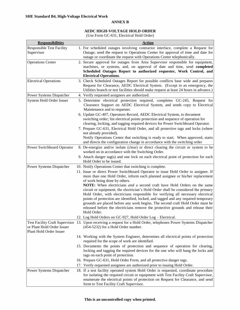
SHE Standard B4, High-Voltage Electrical Work
This is an uncontrolled copy when printed.
ANNEX B
AEDC HIGH-VOLTAGE HOLD ORDER
(Use Form GC-631, Electrical Hold Order)
Responsibilities Action
Responsible Test Facility
Supervisor
1. For scheduled outages involving contractor interface, complete a Request for
Outage; send the request to Operations Center for approval of time and date for
outage or coordinate the request with Operations Center telephonically.
Operations Center 2. Secure approval for outages from Area Supervisor responsible for equipment,
machines, or systems, and, on approval of date and time, send completed
Scheduled Outages Report to authorized requester, Work Control, and
Electrical Operations.
Electrical Operations 3. Check Scheduled Outages Report for possible conflicts base wide and prepares
Request for Clearance, AEDC Electrical System. (Except in an emergency, the
Utilities branch or test facilities should make request at least 24 hours in advance.)
Power Systems Dispatcher 4. Verify requested assignees are authorized.
System Hold Order Issuer 5. Determine electrical protection required, completes GC-245, Request for
Clearance Support on AEDC Electrical System, and sends copy to Electrical
Maintenance and to requester.
6. Update GC-407, Operators Record, AEDC Electrical System, to document
switching order; list electrical points protection and sequence of operation for
clearing, locking, and tagging required devices for Power Switchboard Operator.
7. Prepare GC-631, Electrical Hold Order, and all protective tags and locks (where
not already provided).
Notify Operations Center that switching is ready to start. When approved, starts
and directs the configuration change in accordance with the switching order
Power Switchboard Operator 8. De-energize and/or isolate (clear) or direct clearing the circuit or system to be
worked on in accordance with the Switching Order.
9. Attach danger tag(s) and one lock on each electrical point of protection for each
Hold Order to be issued.
Power Systems Dispatcher 10. Notify Operations Center that switching is complete.
11. Issue or direct Power Switchboard Operator to issue Hold Order to assignee. If
more than one Hold Order, inform each planned assignee or his/her replacement
of work being done by others.
NOTE: When electricians and a second craft have Hold Orders on the same
circuit or equipment, the electrician’s Hold Order shall be considered the primary
Hold Order, with electricians responsible for verifying all necessary electrical
points of protection are identified, locked, and tagged and any required temporary
grounds are placed before any work begins. The second craft Hold Order must be
released before the electricians remove the protective grounds and release their
Hold Order.
12. Log Hold Orders on GC-927, Hold Order Log – Electrical.
Test Facility Craft Supervisor
or Plant Hold Order Issuer
Plant Hold Order Issuer
13.
Upon receiving a request for a Hold Order, telephones Power Systems Dispatcher
(454-5232) for a Hold Order number.
14. Working with the System Engineer, determines all electrical points of protection
required for the scope of work are identified.
15. Documents the points of protection and sequence of operation for clearing,
locking and tagging the required devices for the one who will hang the locks and
tags on each point of protection.
16. Prepare GC-631, Hold Order Form, and all protective danger tags.
17. Verify requested assignees are authorized prior to issuing Hold Order.
Power Systems Dispatcher 18. If a test facility operated system Hold Order is requested, coordinate procedure
for isolating the required circuit or equipment with Test Facility Craft Supervisor,
enumerate the electrical points of protection on Request for Clearance, and send
form to Test Facility Craft Supervisor.
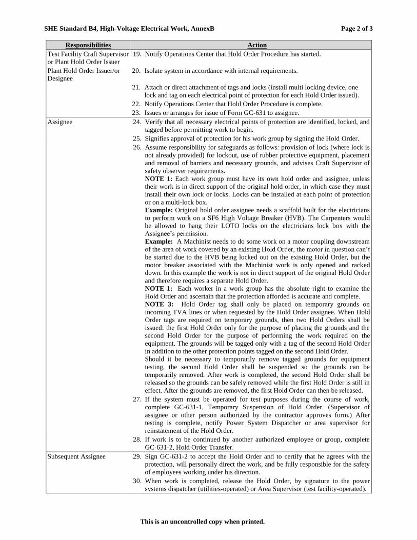
SHE Standard B4, High-Voltage Electrical Work, AnnexB Page 2 of 3
This is an uncontrolled copy when printed.
Responsibilities Action
Test Facility Craft Supervisor
or Plant Hold Order Issuer
19. Notify Operations Center that Hold Order Procedure has started.
Plant Hold Order Issuer/or
Designee
20. Isolate system in accordance with internal requirements.
21. Attach or direct attachment of tags and locks (install multi locking device, one
lock and tag on each electrical point of protection for each Hold Order issued).
22. Notify Operations Center that Hold Order Procedure is complete.
23. Issues or arranges for issue of Form GC-631 to assignee.
Assignee 24. Verify that all necessary electrical points of protection are identified, locked, and
tagged before permitting work to begin.
25. Signifies approval of protection for his work group by signing the Hold Order.
26. Assume responsibility for safeguards as follows: provision of lock (where lock is
not already provided) for lockout, use of rubber protective equipment, placement
and removal of barriers and necessary grounds, and advises Craft Supervisor of
safety observer requirements.
NOTE 1: Each work group must have its own hold order and assignee, unless
their work is in direct support of the original hold order, in which case they must
install their own lock or locks. Locks can be installed at each point of protection
or on a multi-lock box.
Example: Original hold order assignee needs a scaffold built for the electricians
to perform work on a SF6 High Voltage Breaker (HVB). The Carpenters would
be allowed to hang their LOTO locks on the electricians lock box with the
Assignee’s permission.
Example: A Machinist needs to do some work on a motor coupling downstream
of the area of work covered by an existing Hold Order, the motor in question can’t
be started due to the HVB being locked out on the existing Hold Order, but the
motor breaker associated with the Machinist work is only opened and racked
down. In this example the work is not in direct support of the original Hold Order
and therefore requires a separate Hold Order.
NOTE 1: Each worker in a work group has the absolute right to examine the
Hold Order and ascertain that the protection afforded is accurate and complete.
NOTE 3: Hold Order tag shall only be placed on temporary grounds on
incoming TVA lines or when requested by the Hold Order assignee. When Hold
Order tags are required on temporary grounds, then two Hold Orders shall be
issued: the first Hold Order only for the purpose of placing the grounds and the
second Hold Order for the purpose of performing the work required on the
equipment. The grounds will be tagged only with a tag of the second Hold Order
in addition to the other protection points tagged on the second Hold Order.
Should it be necessary to temporarily remove tagged grounds for equipment
testing, the second Hold Order shall be suspended so the grounds can be
temporarily removed. After work is completed, the second Hold Order shall be
released so the grounds can be safely removed while the first Hold Order is still in
effect. After the grounds are removed, the first Hold Order can then be released.
27. If the system must be operated for test purposes during the course of work,
complete GC-631-1, Temporary Suspension of Hold Order. (Supervisor of
assignee or other person authorized by the contractor approves form.) After
testing is complete, notify Power System Dispatcher or area supervisor for
reinstatement of the Hold Order.
28. If work is to be continued by another authorized employee or group, complete
GC-631-2, Hold Order Transfer.
Subsequent Assignee 29. Sign GC-631-2 to accept the Hold Order and to certify that he agrees with the
protection, will personally direct the work, and be fully responsible for the safety
of employees working under his direction.
30. When work is completed, release the Hold Order, by signature to the power
systems dispatcher (utilities-operated) or Area Supervisor (test facility-operated).

SHE Standard B4, High-Voltage Electrical Work, AnnexB Page 3 of 3
This is an uncontrolled copy when printed.
Responsibilities Action
Power Switchboard Operator,
Test Facility Craft
Supervisor, or designee
31. Remove or direct removal of all tags and locks and inspects for removal of
grounds, mechanical blocks, etc.
Assignee or Issuing Official
Power System Dispatcher
32.
33.
Return all Hold Orders and a copy of danger tags to power system dispatcher for
filing.
Retains documentation for 90 days.
Utilities Manager or
Facilities Operation Manager
34. If assignee is absent and unable to transfer or release a Hold Order, may release
Hold Order after investigation and receipt of written recommendation for release
signed by section supervisor responsible for work under hold order and Manager,
Electrical Operations, or area supervisor, depending on jurisdiction.
CAUTION ORDER
Authorized
Requester/Assignee
1. Arrange with the power systems dispatcher or area supervisor to remove
automatic re-closing capability when conditions require work to be done near
energized power lines or cables. Documented on AEDC Electrical Caution Order
(GC Form 946).
Power Systems Dispatcher
Area Supervisor
2. Remove automatic re-closing capability and fastens yellow caution tag (GC Form
200) at re-closing control points.
3.
Log Caution Order number on AEDC Electrical System Caution Order Log and
inform assignee of Caution Order number. Contacts assignee in case circuit trips
before re-energizing circuit.
Authorized
Requester/Assignee 4. When work is completed, call to release caution order.
Power Systems Dispatcher 5.
6.
7.
Remove caution tags, restores re-closing capability, and enter into AEDC
Electrical System Caution Order Log, the time and date.
Retains Caution Order Log for duration of contract.
Retains AEDC Electrical Caution Order (GC Form 946) for 90 days.

SHE Standard B4 High-Voltage Electrical Work
This is an uncontrolled copy when printed.
ANNEX C
EXAMPLE LABELING OF ELECTRICAL EQUIPMENT
TO WARN OF POSSIBLE ARC/FLASH HAZARDS

SHE Standard B4, High-Voltage Electrical Work
This is an uncontrolled copy when printed.
Categories:
No Arc Flash PPE Required o <1.2 cal/cm
2 calculated arc flash hazard
o Color: Green
o No Arc Flash PPE Required - No Arc Flash Boundary requirement
Level 2
o 1.2 through 8 cal/cm2 calculated arc flash hazard
o Color: Yellow
o Minimum Arc Flash PPE Requirements:
Arc-rated (AR) long-sleeve shirt with Arc-rated pants (≥ 8 cal/cm2 rating) or Arc-rated coveralls
(≥8 cal/cm2 rating)
Arc-rated face shield (≥ 8 cal/cm2 rating) and AR Balaclava (≥ 8 cal/cm
2 rating) or arc flash suit
hood
Any optional clothing worn with AR PPE must be non-melting
Hard hat, Safety glasses/goggles, hearing protection, heavy duty leather or AR gloves, leather
work shoes
Level 4
o >8 cal/cm2 up to 40 cal/cm
2 calculated arc flash hazard
o Color: Orange
o Minimum Arc Flash PPE Requirements:
Arc-rated arc flash suit jacket, arc flash suit pants, and arc flash suit hood (≥ 40 cal/cm2 rating)
Any optional clothing worn with AR PPE must be non-melting
Hard hat, Safety glasses/goggles, hearing protection, rubber insulated gloves with AR Gloves,
leather work shoes
NOTE: Non-AR clothing shall not be worn over AR clothing.
ENERGIZED WORK PROHIBITED
o >40 cal/cm2
o Color: Red
o No PPE can protect against the non-thermal hazards for energies above 40 cal/cm2

SHE Standard B4, High-Voltage Electrical Work
This is an uncontrolled copy when printed.
ANNEX D
PPE REQUIREMENTS FOR COMMON LOW-VOLTAGE TASKS WHEN NO ARC FLASH LABEL IS
POSTED ON THE EQUIPMENT
Task (Assumes equipment is energized and work is done within the arc flash boundary)
Equipment Condition Arc Flash
PPE Req’d
Reading a panel meter while operating a meter switch Any No
Normal operation of a circuit breaker (CB), switch, contactor, or starter All of the following:
The equipment is properly installed
The equipment is properly maintained All equipment doors are closed and secured
All equipment covers are in place and secured
There is no evidence of impending failure
No
One or more of the following:
The equipment is not properly installed
The equipment is not properly maintained
Equipment doors are open or not secured
Equipment covers are off or not secured
There is evidence of impending failure
Yes
For ac systems: Work on energized electrical conductors and circuit parts, including voltage testing
Any Yes
For dc systems: Work on energized electrical conductors and circuit parts
of series-connected battery cells, including voltage testing Any Yes
Voltage testing on individual battery cells or individual multi-cell units All of the following:
The equipment is properly installed
The equipment is properly maintained Covers for all other equipment are in place and secured
There is no evidence of impending failure
No
One or more of the following:
The equipment is not properly installed
The equipment is not properly maintained
Equipment doors are open or not secured
Equipment covers are off or not secured
There is evidence of impending failure
Yes
Removal or installation of CBs or switches Any Yes
Removal or installation of covers for equipment such as wireways, junction boxes, and cable trays that does not expose bare energized
electrical conductors and circuit parts
All of the following:
The equipment is properly installed The equipment is properly maintained
There is no evidence of impending failure
No
One or more of the following:
The equipment is not properly installed
The equipment is not properly maintained
There is evidence of impending failure
Yes
Removal of bolted covers (to expose bare energized electrical conductors
and circuit parts). For dc systems, this includes bolted covers, such as battery terminal covers.
Any Yes
Removal of battery intercell connector covers All of the following:
The equipment is properly installed.
The equipment is properly maintained
Covers for all other equipment are in place and secured
There is no evidence of impending failure
No
One or more of the following:
The equipment is not properly installed
The equipment is not properly maintained
Equipment doors are open or not secured
Equipment covers are off or not secured
There is evidence of impending failure
Yes
Opening hinged door(s) or cover(s) (to expose bare energized electrical conductors and circuit parts)
Any Yes

SHE Standard B4, High-Voltage Electrical Work, Annex D Page 2 of 4
This is an uncontrolled copy when printed.
Task (Assumes equipment is energized and work is done within the arc flash boundary)
Equipment Condition Arc Flash
PPE Req’d
Perform infrared thermography and other noncontact inspections outside
the restricted approach boundary. This activity does not include opening of doors or covers.
Any No
Application of temporary protective grounding equipment after voltage test
Any Yes
Work on control circuits with exposed energized electrical conductors and circuit parts, 120 volts or below without any other exposed energized
equipment over 120 V including opening of hinged covers to gain access
Any No
Work on control circuits with exposed energized electrical conductors and circuit parts, greater than 120 V
Any Yes
Insertion or removal of individual starter buckets from motor control center (MCC)
Any Yes
Insertion or removal (racking) of CBs or starters from cubicles, doors open or closed
Any Yes
Insertion or removal of plug-in devices into or from busways Any Yes
Insulated cable examination with no manipulation of cable Any No
Insulated cable examination with manipulation of cable Any Yes
Work on exposed energized electrical conductors and circuit parts of equipment directly supplied by a panelboard or motor control center
Any Yes
Insertion and removal of revenue meters (kW-hour, at primary voltage and current)
Any Yes
For dc systems, insertion or removal of individual cells or multi-cell units of a battery system in an enclosure
Any Yes
For dc systems, insertion or removal of individual cells or multi-cell units of a battery system in an open rack
Any No
For dc systems, maintenance on a single cell of a battery system or multi-
cell units in an open rack Any No
For dc systems, work on exposed energized electrical conductors and circuit parts of utilization equipment directly supplied by a dc source
Any Yes
Arc-resistant switchgear Type 1 or 2 (for clearing times of<0.5 sec with a
prospective fault current not to exceed thearc-resistant rating of the
equipment) and metal enclosedinterrupter switchgear, fused or unfused of
arc resistant typeconstruction, tested in accordance with IEEE C37.20.7:
•Insertion or removal (racking) of CBs from cubicles•Insertion or removal
(racking) of ground and test device•Insertion or removal (racking) of
voltage transformers on or offthe bus
All of the following:
The equipment is properly installed
The equipment is properly maintained
All equipment doors are closed and secured
All equipment covers are in place and secured
There is no evidence of impending failure
No
One or more of the following:
The equipment is not properly installed
The equipment is not properly maintained
Equipment doors are open or not secured
Equipment covers are off or not secured
There is evidence of impending failure
Yes
Opening voltage transformer or control power transformer
compartments Any Yes
Outdoor disconnect switch operation (hookstick operated) at 1
kV through 15 kV Any Yes
Outdoor disconnect switch operation (gang-operated, from
grade) at 1 kV through 15 kV Any Yes
NOTE: Hazard identification is one component of risk assessment. Risk assessment involves a determination of the likelihood of occurrence of an incident, resulting from a hazard that could cause injury or damage to health. The assessment of the likelihood of occurrence contained in this table
does not cover every possible condition or situation. Where this table indicates that arc flash PPE is not required, an arc flash is not likely to occur.
*The phrase properly installed, as used in this table, means that the equipment is installed in accordance with applicable industry codes and
standards and the manufacturer’s recommendations. The phrase properly maintained, as used in this table, means that the equipment has been maintained in accordance with the manufacturer’s recommendations and applicable industry codes and standards. The phrase evidence of impending
failure, as used in this table, means that there is evidence of arcing, overheating, loose or bound equipment parts, visible damage, deterioration, or
other damage.

SHE Standard B4, High-Voltage Electrical Work, Annex D Page 3 of 4
This is an uncontrolled copy when printed.
Arc Flash Hazard PPE Categories for Alternating Current (ac) Systems:
Equipment Arc Flash PPE
Category Arc Flash Boundary
Panelboards or other equipment rated 240 V and below
Parameters: Maximum of 25 kA short-circuit current available; maximum of
0.03 sec (2 cycles) fault clearing time; working distance 455 mm (18 in.)
1 19 in.
Panelboards or other equipment rated >240 V and up to 600 V
Parameters: Maximum of 25 kA short-circuit current available; maximum of
0.03 sec (2 cycles) fault clearing time; working distance 455 mm (18 in.)
2 3 ft
600-V class motor control centers (MCCs)
Parameters: Maximum of 65 kA short-circuit current available; maximum of
0.03 sec (2 cycles) fault clearing time; working distance 455 mm (18 in.)
2 5 ft
600-V class motor control centers (MCCs)
Parameters: Maximum of 42 kA short-circuit current available; maximum of
0.33 sec (20 cycles) fault clearing time; working distance 455 mm (18 in.)
4 14 ft
600-V class switchgear (with power circuit breakers or fused
switches) and 600 V class switchboards
Parameters: Maximum of 35 kA short-circuit current available;
maximum of up to 0.5 sec (30 cycles) fault clearing time;
working distance 455 mm (18 in.)
4 20 ft
Other 600-V class (277 V through 600 V, nominal) equipment
Parameters: Maximum of 65 kA short circuit current available; maximum of
0.03 sec (2 cycles) fault clearing time; working distance 455 mm (18 in.)
2 5 ft
NEMA E2 (fused contactor) motor starters, 2.3 kV through
7.2 kV
Parameters: Maximum of 35 kA short-circuit current available; maximum of
up to 0.24 sec (15 cycles) fault clearing time; working distance 910 mm (36
in.)
4 40 ft
Metal-clad switchgear, 1 kV through 15 kV
Parameters: Maximum of 35 kA short-circuit current available; maximum of
up to 0.24 sec (15 cycles) fault clearing time; working distance 910 mm (36
in.)
4 40 ft
Arc-resistant switchgear Type 1 or 2 [for clearing times of < 0.5 sec (30 cycles)
with a perspective fault current not to exceed the arc-resistant rating of the
equipment], and metal-enclosed interrupter switchgear, fused or unfused of
arc-resistant-type construction, tested in accordance with IEEE C37.20.7, 1 kV
through 15 kV
Parameters: Maximum of 35 kA short-circuit current available; maximum of
up to 0.24 sec (15 cycles) fault clearing time; working distance 910 mm (36
in.)
N/A (doors
closed)
N/A (doors
closed)
4 (doors open) 40 ft
Other equipment 1 kV through 15 kV
Parameters: Maximum of 35 kA short-circuit current available;
maximum of up to 0.24 sec (15 cycles) fault clearing time;
working distance 910 mm (36 in.)
4 40 ft
Note: For equipment rated 600 volts and below, and protected by upstream current-limiting fuses or current-
limiting circuit breakers sized at 200 amperes or less, the arc flash PPE category can be reduced by one number
but not below arc flash PPE category 1.

SHE Standard B4, High-Voltage Electrical Work, Annex D Page 4 of 4
This is an uncontrolled copy when printed.
Arc Flash Hazard PPE Categories for Direct Current (dc) Systems:
Equipment Arc Flash PPE
Category Arc Flash Boundary
Storage batteries, dc switchboards, and other dc supply sources
100 V > Voltage < 250 V
Parameters:
Voltage: 250 V
Maximum arc duration and working distance: 2 sec @ 455 mm (18 in.)
Short-circuit current < 4 kA 1 3 ft
4 kA ≤ short-circuit current < 7 kA 2 4 ft
7 kA ≤ short-circuit current < 15 kA 3 6 ft
Storage batteries, dc switchboards, and other dc supply sources
250 V ≤ Voltage ≤ 600 V
Parameters:
Voltage: 600 V
Maximum arc duration and working distance: 2 sec @ 455 mm (18 in.)
Short-circuit current 1.5 kA 1 3 ft
1.5 kA ≤ short-circuit current < 3 kA 2 4 ft
3 kA ≤ short-circuit current < 7 kA 3 6 ft
7 kA ≤ short-circuit current < 10 kA 4 8 ft
Note: Apparel that can be expected to be exposed to electrolyte must meet both of the following conditions:
(1) Be evaluated for electrolyte protection in accordance with ASTM F1296, Standard Guide for Evaluating
Chemical Protective Clothing
(2) Be arc-rated in accordance with ASTM F1891, Standard Specification for Arc Rated and Flame Resistant
Rainwear, or equivalent

SHE Standard B4, High-Voltage Electrical Work
This is an uncontrolled copy when printed.
ANNEX E
PROTECTIVE CLOTHING AND PERSONAL PROTECTIVE EQUIPMENT (PPE) MATRIX
PPE requirements in SHE Standard F2 must be complied with in addition to the requirements below:
PPE Level Protective Clothing and PPE
PPE Level 2
Arc-rated Clothing, Minimum Arc Rating of 8 (Note 1) Arc-rated long-sleeved shirt Arc-rated pants Arc-rated coverall (Note 3) Arc-rated arc flash suit hood (Note 4) Arc-rated jacket, parka, or rainwear (AN)
Protective Equipment Hard hat Safety glasses or safety goggles (SR) Hearing protection (ear canal inserts) Heavy Duty Leather gloves (Note 2) Leather work shoes
PPE Level 4
Arc-rated Clothing, Minimum Arc Rating of 40 (Note 1) Arc-rated arc flash suit jacket AR
Arc-rated flash suit pants AR
Arc-rated arc flash suit hood
Arc-rated jacket, parka, or rainwear (AN)
Protective Equipment Hard hat
Arc-rated hard hat liner (AR)
Safety glasses or safety goggles (SR)
Hearing protection (ear canal inserts)
Arc-rated gloves (Note 2)
Leather work shoes
AN = As needed (Optional)
AR = As required
SR = Selection required
NOTES:
1. See NFPA 70E Table 130.7(C)(16) Arc rating for a garment or system of garments is expressed in cal/cm2.
2. If rubber insulating gloves with leather protectors are required, additional leather or arc-rated gloves are not
required. The combination of rubber insulating gloves with leather protectors satisfies the arc flash protection
requirement.
3. Alternate is to use FR coveralls (minimum arc rating of 8) instead of FR shirt and FR pants.
4. Alternate is to use face shield with a minimum arc rating of 8 and a balaclava (sock hood) with a minimum arc
rating of 8 which covers the face, head, and neck except for the eye and nose areas.

Supplement NFAC Site
A321-0801-XSP B4 High-Voltage Electrical Work Supplement
Page 1 of 1 This is an uncontrolled copy when printed.
This supplement has been approved for the NFAC Site.
Review: This supplement will be reviewed and updated using the same cycle as AEDC Safety, Health, and Environmental (SHE) Standard B4 High-Voltage Electrical Work.
References: AEDC SHE Standard B4 High-Voltage Electrical Work.
Ames Procedural Requirements APR 1700.1 Chapter 11 Electrical Safety.
Scope:
This supplement outlines the hazards involved, safety equipment required, safety precautions to be observed, and operating procedure requirements when working with high voltage electricity, i.e., greater than 600 volts. Any time a high voltage supply is locked out to provide personnel protection, a hold order shall be required.
This supplement applies in all situations where exposure to energized or potentially energized electrical equipment is possible due to the nature of the work to be performed. Following this standard will help ensure that electrical work is performed under the safest conditions possible.
This supplement applies to all personnel conducting operations, maintenance, testing and support at NFAC, NASA AMES.
NFAC Worksite Application:
NFAC will follow Ames Procedural Requirements APR 1700.1 Chapter 11 Electrical Safety.
Requirements/Responsibilities:
I. NFAC Site Management shall
1. Ensure the supplement is followed.
2. All personnel, customers, and vendors utilize SOPs and Lockout Tagout working with high voltage.
II. NFAC Supervisors and Test Directors shall
1. Ensure the supplement is followed.
2. Ensure staff, customers, and vendors follow the supplement.
3. Ensure that personnel working with High Voltage are qualified.
4. NFAC Electrical Supervisor will issue “Electrical Safety Checklist for Hot Work” A321-0801-XSF-18 for any live circuit work ≥50 volts.
III. NFAC Safety Engineer/Management Designee shall
1. Assess SOPs on High Voltage Electrical Work.
2. Maintain Training records on electrical training (annual) and Lockout Tagout (2 years).
3. Ensure staff is aware of the High Voltage hazards during safety orientation.
4. Perform annual inspection of High Voltage equipment during monthly safety inspection
IV. NFAC Staff shall
1. Follow the supplement.
2. Follow all SOPs, safety protocols, PPE, and Lockout Tagout as required.
3. Maintain training for High Voltage (annual) as required.
4. Obtain signed off “Electrical Safety Checklist for Hot Work” A321-0801-XSF-18 for any live circuit work ≥50 volts.
5. Restrict access to areas during maintenance/trouble shooting operations of high voltage work.
6. Current on Lockout/Tagout Training.