Embed Size (px)
Citation preview

Department of Electronics and Communications Engineering
Performance Analysis of Three Transition Mechanisms Between IPv6
Network and IPv4 Network: Dual Stack, Tunneling and Translation
Prepared By
Durjoy Podder
ID: 2012-2-55-065
Dept. of ECE
East West University
Supervised By
Md. Asif Hossain
Senior Lecturer, Dept. of ECE
April 2016

Letter of Transmittal
To
Md. Asif Hossain
Senior Lecturer
Department of Electronics and Communications Engineering
East West University
Subject: Submission of Project Report as (ETE-498)
Dear Sir,
I am pleased let you know that I have completed my project on “Performance Analysis of Three
Transition Mechanisms between IPv6 Network and IPv4 Network: Dual Stack, Tunneling and Translation
.The attachment contain of the project that has been prepared for your evaluation and consideration.
Working on this project has given me some new concepts. By applying those concepts we have tried to
make something innovative by using my theoretical knowledge which I have acquired since last four
years from you and the other honorable faculty members of EWU. This project would be a great help for
us in future. I am very grateful to you for your guidance, which helped us a lot to complete my project and
acquire practical knowledge.
Thanking You.
Yours Sincerely
Durjoy Podder
ID: 2012-2-55-065
Dept. of ECE
East West University

Declaration
This is certified that the project is done by us under the course “Project (ETE-498)”. The project of
Mechanisms between IPv6 Network and IPv4 Network has not been submitted elsewhere for the
requirement of any degree or any other purpose except for publication.
Durjoy Podder
ID# 2012-2-55-065
Acceptance
This Project paper is submitted to the Department of Electronics and Communications
Engineering, East West University is submitted in partial fulfillment of the requirements for the
degree of B.Sc in ETE under complete supervision of the undersigned.
Asif Hossain
________________
Md. Asif Hossain
Senior Lecturer
Dept. of ECE
East West University

Abstract
Due to the increasing demand of Internet, we are facing a great problem of the depletion of our existing
IPv4 (Internet Protocol version 4) network. To solve the situation, we have to use IP version 6 in coming
years. But the IPv4 network will not be opt out, but also coexist with IPv6 network. For the transition
from IPv4 to IPv6 and vice versa, there are three prominent transition mechanisms are used. They are
Dual Stack, Tunneling and Translation. In this project, the performances of these three mechanisms have
been analyzed. IPv6 header format, its security and the routing also have been focused. For the simulation
Packet Tracer simulation software has been used.
.

TABLE OF CONTENTS
Contents CHAPTER 1: INTRODUCTION .................................................................................................................. 1
CHAPTER 2: OVERVIEW OF IPV6....................................................................................................... 2-12
CHAPTER 3: TRANSITION MECHANISMS BETWEEN IPV4 and IPV6………………………13-16 CHAPTER 4 PACKET TRACER .......................................................................................................... 17-34
CHAPTER 5: IMPLEMENTATION OF THE TRANSITION ……………………………………….35-38
CHAPTER 6: RESULT ANLYSIS ........................................................................................................ 39-41
CHAPTER 7:CONCLUSION ..................................................................................................................... 42
REFERENCES and APENDIX ............................................................................................................. 43-44
Chapter1
Introduction
Every end device and node needs an IP (internet protocol) address to communicate between the hosts.
Address number of currently used IP version 4 is too limited to handle the new demand of IP addresses
[1]. There are some techniques developed to handle this address space problem, they are Network
Address Translation (NAT), Variable Length Subnet Mask (VLSM), Classless Inter domain Routing
(CIDR), Port address translation (PAT) and so on. But these all technology are not able to save the IP
address shortage’s problem. Due to the limitation of IPv4 address, another technology raised: Internet
Protocol Version 6 (IPv6). The IPv6 was designed for sufficient address space for the present and the
future demand for the increasingly growth of internet. IPv6 increases IP address scheme size from IPv4-
32 bits to 128 bits [2]. IPv6 address is cooperated with IPv4 address; this means IPv6 networks is able to
merge with IPv4 networks for the future networks. But, anyhow IPv4 does not support new upcoming
network criteria. The present IPv4 network is huge and complex, so IPv4 could not be replaced by IPv6
suddenly. Migration from one technology to another technology is absolutely difficult, because of IPv4
and IPv6 are not same assemblage for communication. The three prominent transition mechanisms are
widely known as Dual Stack, Tunneling and Network address translation [3].
Though several works have been done on the comparison between these mechanisms [4-8], but still many
problems not resolved yet, calling for huge challenges on IPv6 transitions research. In this paper, the
typical analysis has been done after developing the separate networks for each transition.
The rest of paper has been arranged as follows: in chapter 2, details of IPv6, its format, types and other
features have been discussed. Three transition mechanisms have been discussed in chapter 3. In chapter 4,
the three transitions have been deployed by using packet tracer. Results have been analyzed in chapter 5
and the paper has been concluded in chapter 6.
1
Chapter 2
Overview of IP version 6
History of IPv6
With admirable foresight, the Internet Engineering Task Force (IETF) initiated as early as in 1994, the
design and development of a suite of protocols and standards now known as Internet Protocol Version 6
(IPv6), as a worthy tool to phase out and supplant IPv4 over the coming years. There is an explosion of
sorts in the number and range of IP capable devices that are being released in the market and the usage of
these by an increasingly tech savvy global population. The new protocol aims to effectively support the
ever-expanding Internet usage and functionality, and also address security concerns. IPv6 uses a128-bit
address size compared with the 32-bit system used in IPv4 and will allow for as many as 3.4x1038
possible addresses, enough to cover every inhabitant on planet earth several times over. The 128-bit
system also provides for multiple levels of hierarchy and flexibility in hierarchical addressing and routing,
a feature that is found wanting on the IPv4-based Internet.
A brief recap of the major events in the development of the new protocol is given below:
*
Basic protocol (RFC 2460) published in 1998
*
Basic socket API (RFC 2553) and DHCPv6 (RFC 3315) published in 2003.
*
Mobile IPv6 (RFC 3775) published in 2004
*
Flow label specifications (RFC 3697) added 2004
*
Address architecture (RFC 4291) stable, minor revision in 2006
*
Node requirements (RFC 4294) published 2006
IPv6 Features The massive proliferation of devices, need for newer and more demanding applications on a
global level and the increasing role of networks in the way business is conducted are some of the pressing
issues the IPv6 protocol seeks to cater to. The following are the features of the IPv6 protocol:
2

1.
New header format designed to keep header overhead to a minimum - achieved by
moving both non-essential fields and optional fields to extension headers that are placed
after the IPv6 header. The streamlined IPv6 header is more efficiently processed at
intermediate routers.
2.
Large address space - IPv6 has 128-bit (16-byte) source and destination IP addresses.
The large address space of IPv6 has been designed to allow for multiple levels of
subnetting and address allocation from the Internet backbone to the individual subnets
within an organization. Obviates the need for address-conservation techniques such as
the deployment of NATs.
3.
Efficient and hierarchical addressing and routing infrastructure- based on the common
occurrence of multiple levels of Internet service providers.
4.
Stateless and stateful address configuration both in the absence or presence of a DHCP
server. Hosts on a link automatically configure themselves with link-local addresses and
communicate without manual configuration.
5.
Built-in security: Compliance with IPSec [10] is mandatory in IPv6, and IPSec is
actually a part of the IPv6 protocol. IPv6 provides header extensions that ease the
implementation of encryption, authentication, and Virtual Private Networks (VPNs).
IPSec functionality is basically identical in IPv6 and IPv4, but one benefit of IPv6 is that
IPSec can be utilized along the entire route, from source to destination.
6.
Better support for prioritized delivery thanks to the Flow Label field in the IPv6 header
7.
New protocol for neighboring node interaction- The Neighbor Discovery protocol for
IPv6 replaces the broadcast-based Address Resolution Protocol (ARP), ICMPv4 Router
Discovery, and ICMPv4 Redirect messages with efficient multicast and unicast
Neighbor Discovery messages.
8.
Extensibility- IPv6 can easily be extended for new features by adding extension headers
after the IPv6 header.
3

IPv6 thus holds out the promise of achieving end-to-end security, mobile communications, quality of
service (QoS), and simplified system management.
Representation, format, features and the comparison between IPv4
IPv6 Internet Protocol is developed as the upcoming future network layer protocol, to overcome the
shortages of IPv4 addresses space .The IPv6 is the sixth version of IP address. The IPv6 protocol address
is 128-bit long .To represent the 128 bit address, IPV6 uses total 8 field of consisting 4 hexadecimal
values separated by colons which is represented like(:).So it creates possible 2^128 =
3.4×1038addresses[2]. This is very large number of addresses then IPV4. These new IPv6 address will
meet the Internet demand and it assure to fulfill the needs.
1:1 Unicast addresses 1:n Multicast addresses 1:closest Anycast addresses
Figure 1: Types of IPv6 Addresses
Basically there are 3 types of addressing of IP version 6 these are-
1. Unicast address:
It identifies the signal at the network interface where the IP delivers packets sent to a unicast address to
the specific host to the internet.
2. Anycast address:
In this addressing system the IP address are assigned to a group interfaces and it can be different nodes. It
also used as the identification of the hosts on the internet. If a multicast addresses, sent a packet to an
anycast address it reach only one of the interface in the nearest host. On the contrary any cast addresses
are not be able to identify when the addresses are in the same format as unicast address and only differ
4
Tx
Rx
Tx
Rx Rx Rx
Tx
Rx
Rx

that by the sense of multiple point for this reason it can be said that unicast address working function is
like that anycast addresses.
3. Multicast address:
A multicast address identifies the multiple interfaces on the internet. A packet sent into the all interfaces
in the set which can joined the corresponding multicast group by using multicast address. It is known that
IPV6 does not have broadcast addressing but here broadcast is subsumed by multicast addressing using a
multicast group “ff02::1”.For reducing the hampers of interface the IPV6 protocol use the link-local
multicast group.
The remarkable growth of the Internet Protocol version 4 (IPv4)-based Internet has highlighted several
fundamental limitations with that protocol. Internet Protocol version 6 (IPv6) addresses these issues and
provides additional enhanced services and functionality. IPv6, also called IP-NG, is the “next generation”
Internet Protocol and is the designated successor to IPv4.
Although some aspects of IPv6 are still under development, the basic protocols, conventions, and formats
have been stable for years and enjoy wide support. Real-world production deployment (allocation and
assignment of production network addresses or prefixes) has been underway for several years, and IPv6 is
no longer considered experimental.
The most commonly discussed concern with IPv4 is the perception that IPv4 provides an insufficient
number of individual addresses to meet future needs. While conservation, recovery, and techniques such
as Network Address Translation (NAT) have improved address availability and prolonged the longevity
of the IPv4 address pool, there remains a limit to the future growth of IPv4 due to its 32 bit address fields.
IPv6 dramatically increases this limit by expanding the number of bits in the address fields from 32 bits to
128 bits.
As IPv4 has expanded, IPv4 routing tables have expanded as well. This expansion has heavily taxed the
underlying routing infrastructure. While techniques such as Classless Inter-Domain Routing (CIDR) and
aggregation have slowed this growth, IPv4 use still expands faster than the capacity of the routing
infrastructure. IPv6 deemphasizes growth impact by way of more formalized network and subnetwork
boundaries and aggregation of smaller site networks into aggregation pools and aggregation IDs.
5
Much of the fragmentation of the IPv4 address space has been caused by the inherent difficulty in
renumbering IPv4 networks. IPv6 addresses this limitation through transition mechanisms and auto-
configuration methods that allow dynamic renumbering, multiple addresses, and transition periods which
ease transitions between address prefixes.
IPv6 also improves on many of the security shortcomings that exist in IPv4. In particular, IPv6 contains
many enhanced security features, such as IPSec (AH/ESP), that were back-ported into IPv4. Others, such
as resistance to scanning, are only possible under the IPv6 addressing scheme. For example, the massive
size of the IPv6 address space by itself creates significant barriers to comprehensive vulnerability
scanning.
Other IPv6 features, such as the autoconfiguration of addresses, make it complicated for a malicious
attacker to probe systems for weaknesses. These factors will not stop random or pseudo random scanning,
but they will make it difficult to scan specific IPv6 networks. However, IPv6 networks can be scanned
effectively if they are poorly designed (as in the traditional IPv4 model) and use dense address allocations
and/or well-known addresses for services and routers.
Auto configuration makes IPv6 relatively easy to setup and renumber on demand. Consequently, it also
makes it easy for an intruder who has already gained access to a local subnetwork to announce rogue
routes and routers to further an attack, or to route multiple compromised systems through tunnels under
illicit control.
Transition tunnels and tunneling routers make it possible to deploy islands of IPv6 support within a larger
sea of IPv4 networks without having the IPv6 routers directly connected to each other -- or even requiring
IPv6 routers at all. This arrangement allows intruders to subvert simple workstations and use them as
routers to direct traffic across entire subnetworks without having to compromise infrastructure routers or
firewalls.
IPv6 Address Format:
IPV6 address use basically 128 bit for IP addressing and this 128 bits are separated by eight groups each
groups have sixteen bit and they are separated by colons “:”.For Examples “
2000:db80:0448:5a73:0000:0000:0000:0001” here it can noticed that every later is used in small letter
6
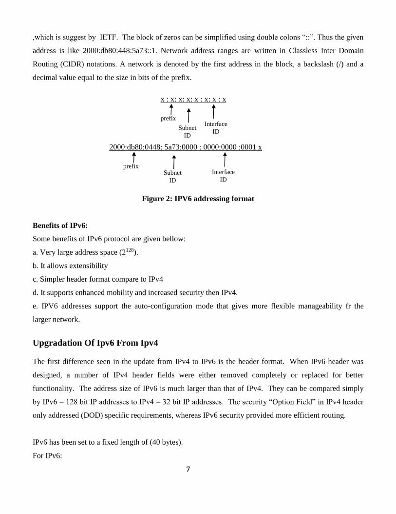
,which is suggest by IETF. The block of zeros can be simplified using double colons “::”. Thus the given
address is like 2000:db80:448:5a73::1. Network address ranges are written in Classless Inter Domain
Routing (CIDR) notations. A network is denoted by the first address in the block, a backslash (/) and a
decimal value equal to the size in bits of the prefix.
Figure 2: IPV6 addressing format
Benefits of IPv6:
Some benefits of IPv6 protocol are given bellow:
a. Very large address space (2128).
b. It allows extensibility
c. Simpler header format compare to IPv4
d. It supports enhanced mobility and increased security then IPv4.
e. IPV6 addresses support the auto-configuration mode that gives more flexible manageability fr the
larger network.
Upgradation Of Ipv6 From Ipv4
The first difference seen in the update from IPv4 to IPv6 is the header format. When IPv6 header was
designed, a number of IPv4 header fields were either removed completely or replaced for better
functionality. The address size of IPv6 is much larger than that of IPv4. They can be compared simply
by IPv6 = 128 bit IP addresses to IPv4 = 32 bit IP addresses. The security “Option Field” in IPv4 header
only addressed (DOD) specific requirements, whereas IPv6 security provided more efficient routing.
IPv6 has been set to a fixed length of (40 bytes).
For IPv6:
7
Subnet
ID
x : x: x: x: x : x: x : x prefix
Interface
ID
Subnet
ID
2000:db80:0448: 5a73:0000 : 0000:0000 :0001 x prefix
Interface
ID

The “Header Length” was replaced by “Fixed Length”.
The “Total Length” was replaced by “Payload Length”.
IPv4 “Segmentation Control” fields were moved into IPv6 “Fragmentation Extension Header”.
IPv4 “Type of Service” is now known as IPv6 “Traffic Class”
The Total Length” was replaced by “Payload Length”
The “Time to Live” was replaced by “Hop Limit”
The “Protocol” was replaced by “Next Header Type”.
IPV4 HEADER FORMATE:
Figure 3: IPv4 Header architecture
8

IPV6 HEADER FORMATE:
Figure 4: IPv6 Header architecture
Upgrade of IPV6:
IPv4 is the basis of the TCP/IP communication protocols which are used to transport data, voice and
video packets over the Internet. It is well known that in today's IPv4-based Internet, the relatively limited
number of available addresses has encouraged the use of certain techniques and technologies, such as
Network Address Translation (NAT) in particular. These technologies have compromised the ability of
the network to diversify in terms of applications. The limited size of IPv4 address space imposes a strict
limit on the ability of the network to grow substantially, for instance to two or three orders of magnitude
larger than today's Internet. If such growth were to occur using IPv4 address space, additional and
substantial architectural compromise would be required, which would further reduce the simplicity,
integrity and uniformity of the network. Due to recent concerns over the impending depletion of the
current pool of Internet addresses and the desire to provide additional functionality for modern devices, an
upgrade of the current version of the Internet Protocol (IP), called IPv4, has been defined. This new
version, called IP version 6 (IPv6), resolves unanticipated IPv4 design issues and takes the Internet into
the 21st Century. This paper describes the problems of the IPv4 Internet and how they are solved by IPv6,
the new features introduced in the emerging Internet Protocol standard and why they have been
introduced. IPv6 addressing, the new IPv6 header and its extensions, the IPv6 replacements for the
Internet Control Message Protocol (ICMP) and Internet Group Management Protocol (IGMP),
neighboring node interaction, and IPv6 address auto configuration. This paper provides a foundation of
9

Internet standards-based IPv6 concepts and is intended for network engineers and support professionals
who are already familiar with basic networking concepts and TCP/IP. INTRODUCTION IPv6 is gaining
momentum worldwide, driven by the need for more IP addresses than IPv4 can provide. Internet Protocol
version 6 (IPv6) is the next generation network protocol which has been standardized to replace the
current Internet protocol version 4. It holds great promise to be the backbone of the next generation
Internet and offer a significant improvement over IPv4 in terms of scalability, security, mobility and
convergence. The basic framework of the IPv6 protocol was standardized by IETF (Internet Engineering
Task Force) in the 1990s. However, there is still ongoing development of certain advanced aspects of the
protocol. The exponential growth of the Internet is the main reason that has required the creation of the
next generation of Internet Protocol-IPv6. IPv6 is much more flexible and promises to take care of the
address space and security issues in the foreseeable future.
Limitations of IPv4 :
IPv4 has proven to be robust, easily implemented and interoperable, and has stood the test of scaling an
internetwork to a global utility the size of today’s Internet. This is a tribute to its initial design. However,
the initial design did not anticipate the following:
The recent exponential growth of the Internet and the impending exhaustion of the IPv4 address space.
IPv4 addresses have become relatively scarce, forcing some organizations to use a Network Address
Translator (NAT) to map multiple private addresses to a single public IP address. While NATs promote
reuse of the private address space, they do not support standards-based network layer security or the
correct mapping of all higher layer protocols and can create problems when connecting two organizations
that use the private address space.
Ipv6 Addressing Plan
The IPv6 address range allocated to BSNL by APNIC is 2001:4490::/30. However since BSNL is entitled
for /24 address space and a larger address space will be future safe, the same should be requested to
APNIC.
Following would require IPv6 addressing
BSNL servers, backbone and access equipment.
Leased Line Customers
10

Enterprise customer with multiple location (connected through leased lines or over MPLS)
Broadband (ADSL) Customers
Mobile Wireless (GSM, CDMA, 3G) customers
Multiplay Customers
WiMAX Customers
ISPs who are taking bandwidth from BSNL
IPv6 services will not be offered to Narrow-band Dial-up customers.
Following Hierarchical Address Allocation Policy may be used:
Allocate address range to various PoPs as follows:
o /34 for A1 & A2 PoPs
o /36 for A3 & A4 PoPs
o /38 for B1 & B2 PoP s
Within each PoP, allocate address range as follows:
o In all A1 & A2 PoPs, use /38 for various services like Broadband, Mobile,
Multiplay, WiMAX, leased line customers (including ISPs) and BSNL service
networks.
o In all A3 & A4 PoPs, use /40 for various services like Broadband, Mobile, Multiplay,
WiMAX, leased line customers (including ISPs) and BSNL service networks.
o In all B1 & B2 PoPs, use /42 for various services like Broadband, Mobile, Multiplay,
WiMAX, leased line customers (including ISPs) and BSNL service networks.
Allocate address range to customers as follows:
o Allocate /64 IP address to broadband, mobile wireless, WiMAX and multiplay
customers.
o Allocate /56 to large Leased Line customers & /60 for small leased line customers
and BSNL service networks.
o Allocate multiple /56 or /60 to multi-location leased line customer.
o Allocate multiple /56 to ISPs.
Allocate 1 /40 address range for all the routers and other network devices. All the IPv6 related
routing and IPv6 SNMP management should be done using these IPs.
11

RFCs 3531, RFC 4007, RFC 4291, RFC 5375 related to IPv6 address assignment may be referred to for
details.
IPv6 Routing
The complete NIB network needs to be configured for routing IPv6 traffic. Since the core backbone is
MPLS, it is recommended that the IPv6 traffic should be routed through VPN tunnels over the MPLS
cloud.
So no configuration change is required in Core Routers. The PE routers should be configured as 6PE
routers so that the IPv6 traffic can routed over MPLS core backbone.
This feature has already been tested on the PE routers at Noida and Banglore NOC. Annexure II details
how PE routers at Noida and Banglore NOC have been configured as 6PE routers to route IPv6 traffic
over the NIB MPLS backbone. Similar configuration can be replicated in all the PE routers.
The routing of IPv6 traffic from customer premises to the PE Routers will be native IPv6 routing. So the
Customer Edge equipment, Central Office Access equipment and PE Routers should be configured to
support dual stack IPv4 and IPv6 routing.
Actions Required:
1. Plan IPv6 routing in the Backbone and Customer Edge.
2. Configure PE Routers as 6PE Routers.
3. Configure all Central Office Access equipment for Dual Stack IPv4/IPv6 .
IPv6 Peering
To enable all the BSNL customers to be able to access Internet over IPv6 and run IP based applications
(e.g. VoIP) over IPv6, the peering with upstream provider(s) and other peering ISP(s) needs to be enabled
for routing IPv6 traffic.
12

Actions Required:
1. Request upstream provider(s) to announce BSNL’s Ipv6 addresses and enable Ipv6 routing
between BSNL NIB network and their network.
2. Study the existing peering arrangements and enable Ipv6 peering with other peering partners.
IPv6 Application Servers
In order to support IPv6 services for BSNL customers, the application servers need to be enabled for
supporting IPv6. Initially at-least DNS and Web Server(s) should be configured to support IPv6. The
steps required to setup an IPv6 DNS and Web server are given in Annexure III.
Actions Required:
1. Upgrade some of the existing Internet Name Servers and Web Servers being run by BSNL
for its customers to support IPv6.
2. A basic understanding of IPv6 addressing, its structure, and how it was defined is an
important foundation for identifying the sources of the risks associated with IPv6 and its
users and abusers.
3. IPv6 addresses look more intimidating than IPv4 addresses. Instead of four “octets”
(number 0-255) separated by dots (a dotted quad), IPv6 addresses are a series of 16 bit hex
numbers (number 0-ffff) separated by colons. There can be up to 8 of these numbers
representing a single IPv6 address. There is, additionally, a shorthand notation in which
“::” represents any number of “zero words.”
4. Examples:
IPv4: 192.168.16.131
IPv6 (no zero words): 2001:470:104:20:202:b3ff:fead:42ba
IPv6 (with zero words): 2001:470:104:20:0:0:0:1
IPv6 (with zero shorthand): 2001:470:104:20::1 (previous example :0:0:0: = ::)
5. IPv6 addresses are well structured and can actually be simpler to understand than IPv4
addresses, which may have arbitrary CIDR (Classless Inter-Domain Routing) network
boundaries and subnets, and similar complications.
13

6. The entire top-level range of 2000::/3 (2000::/16 through 3fff::/16) is meant to be allocated for
globally routable addresses. This range currently contains several prefix allocations, all of which are
routable, with different purposes, allocation schemes, and formats. The 2001::/16 prefix is allocated
for production IPv6 Internet assignments, while 3ffe::/16 is currently allocated for the 6Bone, the
experimental test bed. The 2002::/16 prefix is used for 6to4 SIT auto tunnels, described below. On
networks that do not intend to support IPv6, a Network IDS can be configured to detect IP traffic with
a version number 6 in the IP header. This presence could be indicative of malicious, or at least, non-
supported network traffic if IPv6 is unsupported and could pose a potential security threat if rogue
IPv6 routers are present.
12

Chapter 3
Transition Mechanisms between
IPV4 and IPV6:
There are three mechanisms are currently used for IPv4 to IPv6 transition. They are: dual stack, tunneling
and network address translation.
3.1 Dual Stack:
Dual stack is a common and core system of transition techniques between IPV4 and IPV6 network. As
stated earlier Dual Stack technique is allow to apply between an IPv4 and IPv6 address it has to defined
on the same network interface, it means that we can use a router but we have to use separate interface for
both ipv6 addressing. In the dual stack implementation all the network devices like workstations, servers,
routers, and so on. In order to implement dual stack all the devices need to support both the IP versions
and extra processing power and simultaneously handle both the protocols.In Figure 3, a typical dual stack
scenario has been shown.
13
TCP UDP
IPv4 IPv6
Ethernet FDDI PPP etc
IPv4/ IPv6 Application
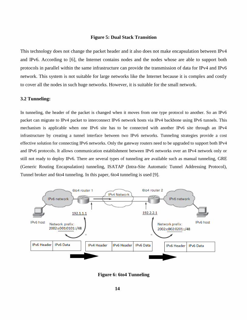
Figure 5: Dual Stack Transition
This technology does not change the packet header and it also does not make encapsulation between IPv4
and IPv6. According to [6], the Internet contains nodes and the nodes whose are able to support both
protocols in parallel within the same infrastructure can provide the transmission of data for IPv4 and IPv6
network. This system is not suitable for large networks like the Internet because it is complex and costly
to cover all the nodes in such huge networks. However, it is suitable for the small network.
3.2 Tunneling:
In tunneling, the header of the packet is changed when it moves from one type protocol to another. So an IPv6
packet can migrate to IPv4 packet to interconnect IPv6 network hosts via IPv4 backbone using IPv6 tunnels. This
mechanism is applicable when one IPv6 site has to be connected with another IPv6 site through an IPv4
infrastructure by creating a tunnel interface between two IPv6 networks. Tunneling strategies provide a cost
effective solution for connecting IPv6 networks. Only the gateway routers need to be upgraded to support both IPv4
and IPv6 protocols. It allows communication establishment between IPv6 networks over an IPv4 network only or
still not ready to deploy IPv6. There are several types of tunneling are available such as manual tunneling, GRE
(Generic Routing Encapsulation) tunneling, ISATAP (Intra-Site Automatic Tunnel Addressing Protocol),
Tunnel broker and 6to4 tunneling. In this paper, 6to4 tunneling is used [9].
Figure 6: 6to4 Tunneling
14

From the Figure 4. It is shown that two IPv6 hosts from two different networks are connecting each other
through IPv4 network infrastructure. The IPv6 packets are encapsulated inside IPv4 packets for the
transmission within IPv4 network. The global IPv4 address that is assigned to a host, a 48-bit 6to4 IPv6
prefix can be constructed by that host by appending the IPv4 address to 2002::/16. For example, the
global IPv4 address 192.1.1.1 has the corresponding 6to4 prefix 2002:c001:0101::/48 (known as 6to4
address) This gives a prefix length of 48 bits, which leaves space for a 16-bit subnet field and 64 bit host
addresses within that subnets [10].
3.3 Translation:
This mechanism of transition changes the header format from IPv4 to IPv6 format and vice versa. This
scheme translate the packet from both the addresses. By using this translation, IPv6only hosts can
communicate with IPv4only hosts. Translation methods are of two types, such as stateless and stateful.
The stateless translation, the packets are not interrelated to each other while the stateful translation is
interrelated to each other.
Figure 7: NAT-PT Transition
In this paper, NAT-PT (Network Address Translation--Protocol Translation) mechanism has been used.
15

Chapter 4
Packet Tracer
What is Packet Tracer?
Packet Tracer is a protocol simulator developed by Dennis Frezzo and his team at Cisco Systems. Packet
Tracer (PT) is a powerful and dynamic tool that displays the various protocols used in networking, in
either Real Time or Simulation mode. This includes layer 2 protocols such as Ethernet and PPP, layer 3
protocols such as IP, ICMP, and ARP, and layer 4 protocols such as TCP and UDP. Routing protocols
can also be traced.
Purpose:
The purpose of this lab is to become familiar with building topologies in Packet Tracer.
Requisite knowledge:
This lab assumes some understanding of the Ethernet protocol. At this point we have not discussed other
protocols, but will use Packet Tracer in later labs to discuss those as well.
16

Version:
This lab is based on Packet Tracer 6.0
Step 1: Start Packet Tracer
Step 2: Choosing Devices and Connections
We will begin building our network topology by selecting devices and the media in which to connect
them. Several types of devices and network connections can be used. For this lab we will keep it simple
by using End Devices, Switches, Hubs, and Connections.
17

Single click on each group of devices and connections to display the various choices. The devices you see
may differ slightly.
18

Step 3: Building the Topology – Adding Hosts
Single click on the End Devices.
Single click on the Generic host.
Move the cursor into topology area. You will notice it turns into a plus “+” sign.
Single click in the topology area and it copies the device.
19

Add three more hosts.
Step 4: Building the Topology – Connecting the Hosts to Hubs and Switches
Adding a Hub
Select a hub, by clicking once on Hubs and once on a Generic hub.
Add the hub by moving the plus sign “+” below PC0 and PC1 and click once.
Connect PC0 to Hub0 by first choosing Connections.
20
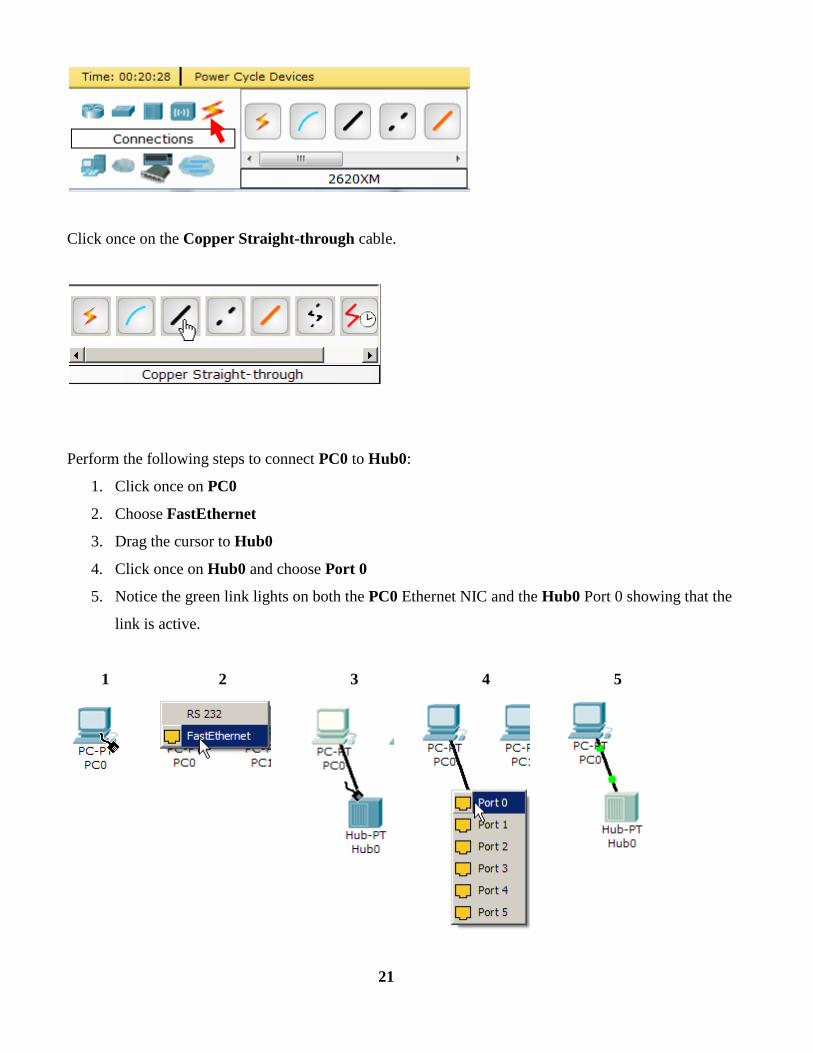
Click once on the Copper Straight-through cable.
Perform the following steps to connect PC0 to Hub0:
1. Click once on PC0
2. Choose FastEthernet
3. Drag the cursor to Hub0
4. Click once on Hub0 and choose Port 0
5. Notice the green link lights on both the PC0 Ethernet NIC and the Hub0 Port 0 showing that the
link is active.
1 2 3 4 5
21

Repeat the steps above for PC1 connecting it to Port 1 on Hub0. (The actual hub port you choose does
not matter.)
Adding a Switch
Select a switch, by clicking once on Switches and once on a 2950-24 switch.
Add the switch by moving the plus sign “+” below PC2 and PC3 and click once.
22

Connect PC2 to Hub0 by first choosing Connections.
Click once on the Copper Straight-through cable.
Perform the following steps to connect PC2 to Switch0:
1. Click once on PC2
2. Choose FastEthernet
3. Drag the cursor to Switch0
4. Click once on Switch0 and choose FastEthernet0/1
5. Notice the green link lights on PC2 Ethernet NIC and amber light Switch0 FastEthernet0/1 port.
The switch port is temporarily not forwarding frames, while it goes through the stages for the
Spanning Tree Protocol (STP) process.
6. After a about 30 seconds the amber light will change to green indicating that the port has entered
the forwarding stage. Frames can now forwarded out the switch port.
Note: Spanning Tree Protocol (STP) is discussed later.
23
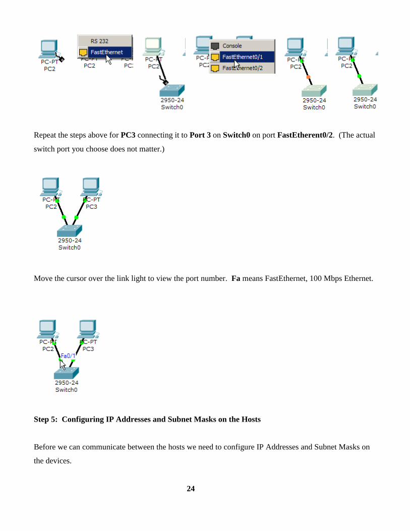
Repeat the steps above for PC3 connecting it to Port 3 on Switch0 on port FastEtherent0/2. (The actual
switch port you choose does not matter.)
Move the cursor over the link light to view the port number. Fa means FastEthernet, 100 Mbps Ethernet.
Step 5: Configuring IP Addresses and Subnet Masks on the Hosts
Before we can communicate between the hosts we need to configure IP Addresses and Subnet Masks on
the devices.
24
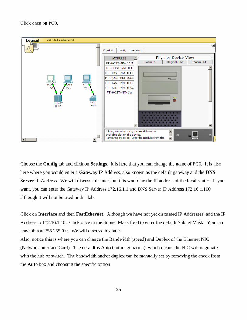
Click once on PC0.
Choose the Config tab and click on Settings. It is here that you can change the name of PC0. It is also
here where you would enter a Gateway IP Address, also known as the default gateway and the DNS
Server IP Address. We will discuss this later, but this would be the IP address of the local router. If you
want, you can enter the Gateway IP Address 172.16.1.1 and DNS Server IP Address 172.16.1.100,
although it will not be used in this lab.
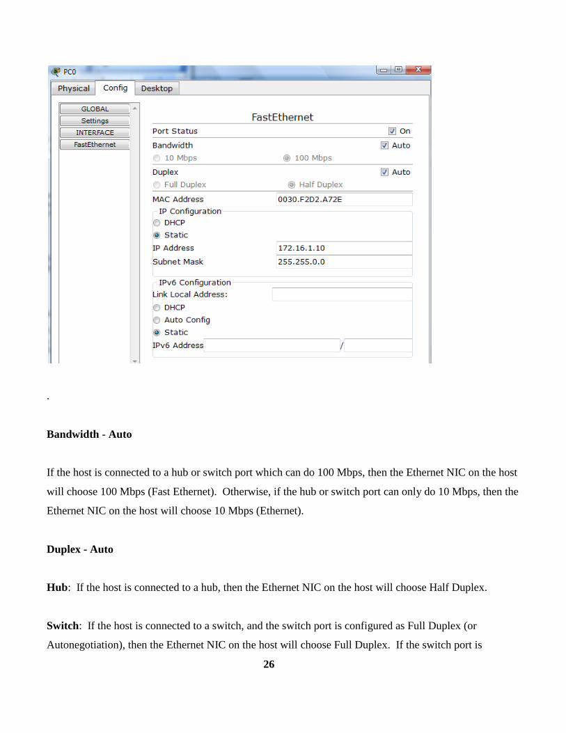
Click on Interface and then FastEthernet. Although we have not yet discussed IP Addresses, add the IP
Address to 172.16.1.10. Click once in the Subnet Mask field to enter the default Subnet Mask. You can
leave this at 255.255.0.0. We will discuss this later.
Also, notice this is where you can change the Bandwidth (speed) and Duplex of the Ethernet NIC
(Network Interface Card). The default is Auto (autonegotiation), which means the NIC will negotiate
with the hub or switch. The bandwidth and/or duplex can be manually set by removing the check from
the Auto box and choosing the specific option
25
.
Bandwidth - Auto
If the host is connected to a hub or switch port which can do 100 Mbps, then the Ethernet NIC on the host
will choose 100 Mbps (Fast Ethernet). Otherwise, if the hub or switch port can only do 10 Mbps, then the
Ethernet NIC on the host will choose 10 Mbps (Ethernet).
Duplex - Auto
Hub: If the host is connected to a hub, then the Ethernet NIC on the host will choose Half Duplex.
Switch: If the host is connected to a switch, and the switch port is configured as Full Duplex (or
Autonegotiation), then the Ethernet NIC on the host will choose Full Duplex. If the switch port is
26
configured as Half Duplex, then the Ethernet NIC on the host will choose Half Duplex. (Full Duplex is a
much more efficient option.)
The information is automatically saved when entered.
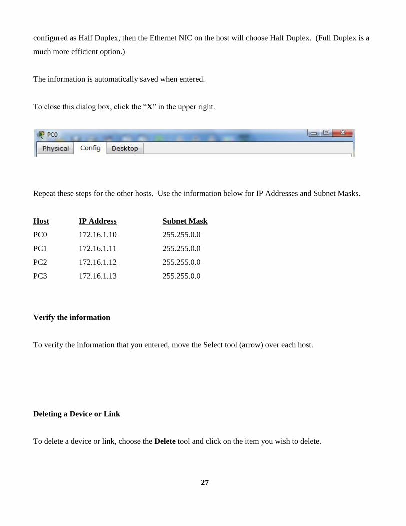
To close this dialog box, click the “X” in the upper right.
Repeat these steps for the other hosts. Use the information below for IP Addresses and Subnet Masks.
Host IP Address Subnet Mask
PC0 172.16.1.10 255.255.0.0
PC1 172.16.1.11 255.255.0.0
PC2 172.16.1.12 255.255.0.0
PC3 172.16.1.13 255.255.0.0
Verify the information
To verify the information that you entered, move the Select tool (arrow) over each host.
Deleting a Device or Link
To delete a device or link, choose the Delete tool and click on the item you wish to delete.
27
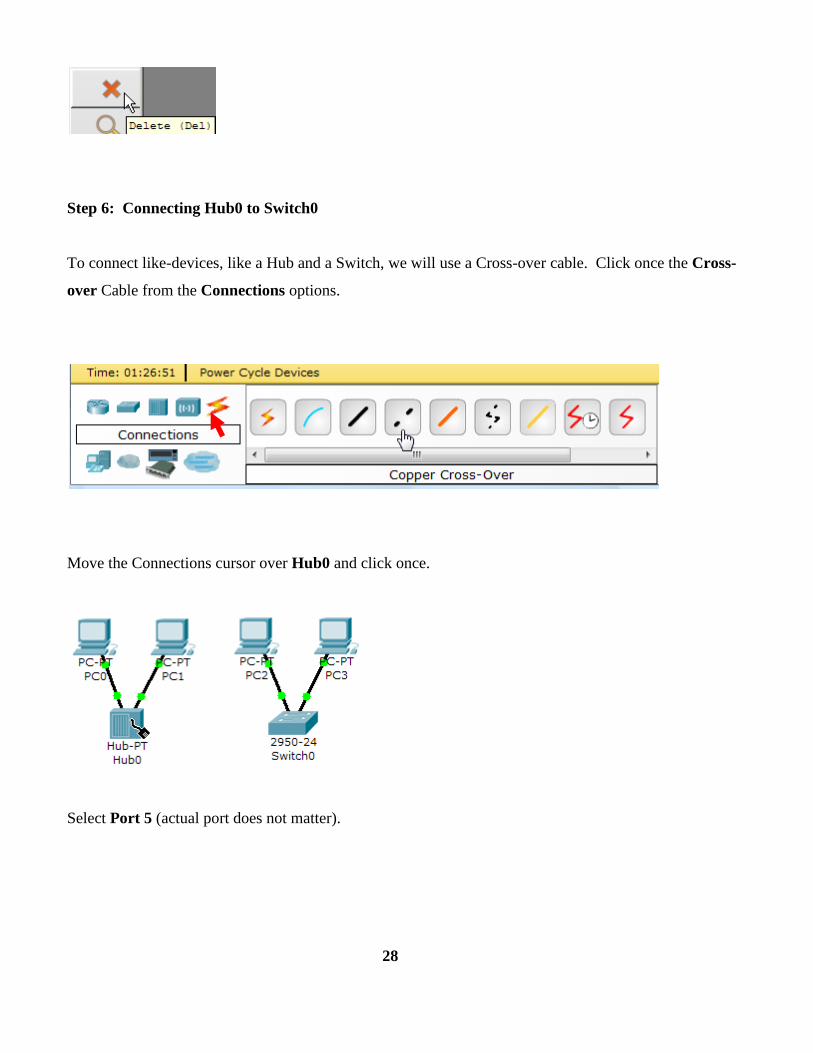
Step 6: Connecting Hub0 to Switch0
To connect like-devices, like a Hub and a Switch, we will use a Cross-over cable. Click once the Cross-
over Cable from the Connections options.
Move the Connections cursor over Hub0 and click once.
Select Port 5 (actual port does not matter).
28

Move the Connections cursor to Switch0.
Click once on Switch0 and choose FastEthernet0/4 (actual port does not matter).
The link light for switch port FastEthernet0/4 will begin as amber and eventually change to green as the
Spanning Tree Protocol transitions the port to forwarding.
29
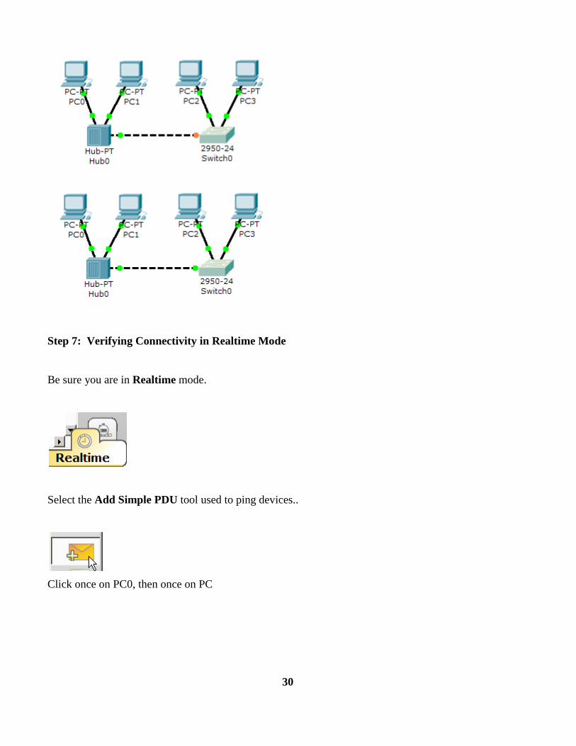
Step 7: Verifying Connectivity in Realtime Mode
Be sure you are in Realtime mode.
Select the Add Simple PDU tool used to ping devices..
Click once on PC0, then once on PC
30

The PDU Last Status should show as Successful.
Resetting the Network
At this point we will want to reset the network, Whenever you want to reset the network and begin the
simulation again, perform the following tasks:
Click Delete in the PDU area.
31
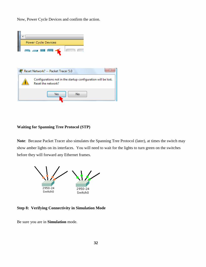
Now, Power Cycle Devices and confirm the action.
Waiting for Spanning Tree Protocol (STP)
Note: Because Packet Tracer also simulates the Spanning Tree Protocol (later), at times the switch may
show amber lights on its interfaces. You will need to wait for the lights to turn green on the switches
before they will forward any Ethernet frames.
Step 8: Verifying Connectivity in Simulation Mode
Be sure you are in Simulation mode.
32

Deselect all filters (All/None) and select only ICMP.
33
1
2
3

Select the Add Simple PDU tool used to ping devices..
Click once on PC0, then once on PC3.
Continue clicking Capture/Forward button until the ICMP ping is completed. You should see the ICMP
messages move between the hosts, hub and switch. The PDU Last Status should show as Successful.
Click on Clear Event List if you do not want to look at the events or click Preview Previous Events if
you do. For this exercise it does not matter.

Chapter 5
Implementation of the Transition
5.1Dual Stack:
The following topology has been developed in Packet Tracer 6.2 to implement the dual stack transition.
Figure 6: Dual-stack system
For the above topology, the following key configuration codes have been used:
Router(config)#router rip
35

Router(config-router)#no auto-summary
Router(config)#ipv6 unicast-routing
Router(config)#ipv6 router rip cisco
Router(config)#interface gigabitEthernet 0/1
Router(config-if)#ipv6 rip cisco enable
Router(config-if)#exit
In Figure. 6, a server having both IPv4 and IPv6 address configured, for that it can now communicate
with all the hosts on both the IPv4 and the IPv6 networks with the help of a Dual Stack Router.
5.2 Tunneling:
For developing the scenario for tunneling transition, the following topology and the configurations have
used:
Figure 7: Tunneling system
Some main configuration codes:
36

Router(config-router)#network 192.23.1.0 0.0.0.255 area 0
Router(config-if)#ip address 192.23.1.2 255.255.255.0
Router(config-if)#ipv6 address 2000:1:1:1:1:1:1:1111/112
Router(config)#ipv6 unicast-routing
Router(config)#interface tunnel 10
Router(config-if)#ipv6 rip 6bone enable
Router(config-if)#tunnel source serial 0/0/0
Router(config-if)#tunnel destination 192.34.1.4
Router(config-if)#tunnel mode ipv6ip
Router(config-if)#duplex auto
Router(config-if)#speed auto
The above diagram depicts how two remote IPv4 networks can communicate via a Tunnel, where the
transit network was on IPv6. Vice versa is also possible where the transit network is on IPv6 and the
remote sites that intend to communicate are on IPv4.
5.3 NAT Protocol Translation
Figure 8:NAT translation system
37
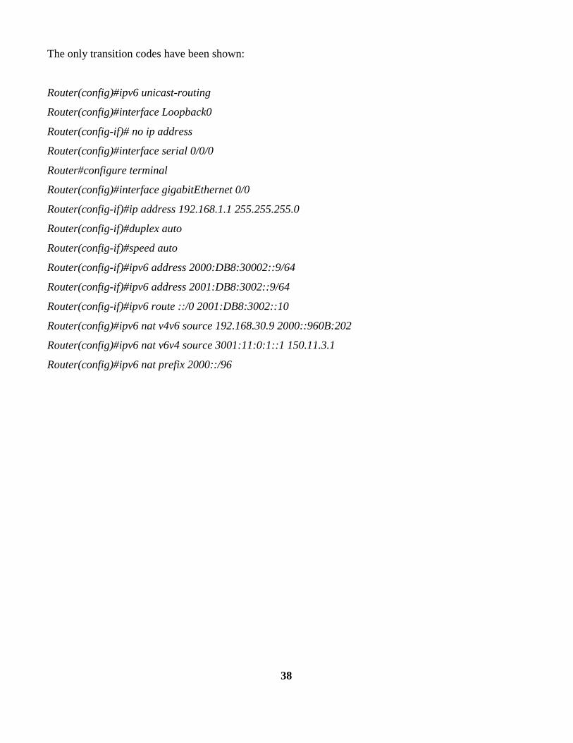
The only transition codes have been shown:
Router(config)#ipv6 unicast-routing
Router(config)#interface Loopback0
Router(config-if)# no ip address
Router(config)#interface serial 0/0/0
Router#configure terminal
Router(config)#interface gigabitEthernet 0/0
Router(config-if)#ip address 192.168.1.1 255.255.255.0
Router(config-if)#duplex auto
Router(config-if)#speed auto
Router(config-if)#ipv6 address 2000:DB8:30002::9/64
Router(config-if)#ipv6 address 2001:DB8:3002::9/64
Router(config-if)#ipv6 route ::/0 2001:DB8:3002::10
Router(config)#ipv6 nat v4v6 source 192.168.30.9 2000::960B:202
Router(config)#ipv6 nat v6v4 source 3001:11:0:1::1 150.11.3.1
Router(config)#ipv6 nat prefix 2000::/96
38

Chapter 6
Result Analysis
In this paper, the latency analysis, the throughput analysis and the packet lossanalysis have been done.
After deploying the above topologies of the transition mechanisms, some complex Protocol Data Unit
(PDU) have been transferred from one host another host. After observing the packet transmissions, the
following results have been found:
Figure 9: Latency Analysis of the transition mechanisms
From the Figure 9, it has been found that the NAT-PT transition gives the highest latency, while Dual
stack provides the moderate and the Tunneling mechanism provides the lowest latency.
39
0
50
100
150
200
250
50 100 150 200 250 300 350 400 450 500
Tim
e (m
s)
Packet Size (Byte)
Latency between various transition for various packet size
Tunneling
Dual Stack
NAT-PT
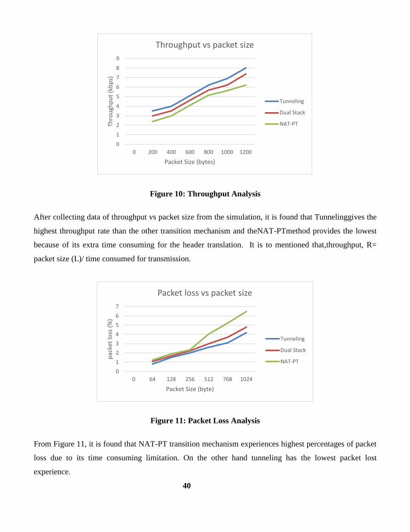
Figure 10: Throughput Analysis
After collecting data of throughput vs packet size from the simulation, it is found that Tunnelinggives the
highest throughput rate than the other transition mechanism and theNAT-PTmethod provides the lowest
because of its extra time consuming for the header translation. It is to mentioned that,throughput, R=
packet size (L)/ time consumed for transmission.
Figure 11: Packet Loss Analysis
From Figure 11, it is found that NAT-PT transition mechanism experiences highest percentages of packet
loss due to its time consuming limitation. On the other hand tunneling has the lowest packet lost
experience.
40
0
1
2
3
4
5
6
7
8
9
0 200 400 600 800 1000 1200
Thro
ugh
pu
t (k
bp
s)
Packet Size (bytes)
Throughput vs packet size
Tunneling
Dual Stack
NAT-PT
0
1
2
3
4
5
6
7
0 64 128 256 512 768 1024
pac
ket
loss
(%
)
Packet Size (byte)
Packet loss vs packet size
Tunneling
Dual Stack
NAT-PT
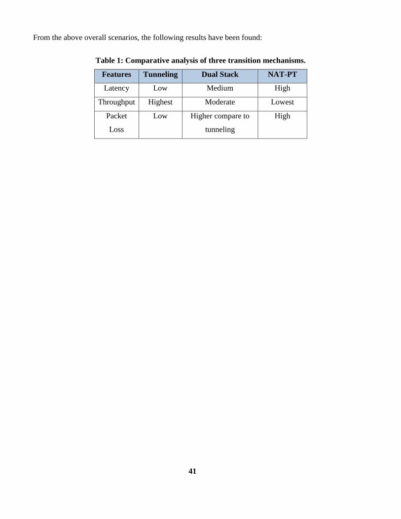
From the above overall scenarios, the following results have been found:
Table 1: Comparative analysis of three transition mechanisms.
Features Tunneling Dual Stack NAT-PT
Latency Low Medium High
Throughput Highest Moderate Lowest
Packet
Loss
Low Higher compare to
tunneling
High
41
Chapter 7
Conclusion
In this project, the three mechanisms of IPv6 to IPv4 transition have discussed, deployed and analyzed. It
has been found that three mechanisms have distinct features and advantages with some disadvantages.
The appropriate transition mechanism will be chosen for the network based on various parameters like the
size of the network, the availability of the latest devices, the cost, the security concern and so on. Some of
them have been focused on this paper with the simulation results. If latency, throughput and packet loss
are considered then tunneling method is the best choice while the NAT-PT is the worst. But tunneling
method has some security issues that will be solved by IPsec (IP security). In future, the paper will be
extended by including this security concern in details. The analysis also be further expanded in NS3
simulator and also in real devices.
Reference
[1] G. Huston, “IPv4 Address Report.” http://www.potaroo.net/tools/ipv4/index.html., 2010
[2]Hinden, R. and S. Deering, "Internet Protocol Version 6 (IPv6) Addressing Architecture", RFC 3513,
April 2005.
[3] J. Bi, J. Wu, and X. Leng, "IPv4/IPv6 Transition Technologies and Univer6 Architecture", IJCSNS,
Vol. 7, No. 1, pp. 232-242, January 2007.
[4] Raicu, I.; Zeadally, S., "Evaluating IPv4 to IPv6 transition mechanisms," in Telecommunications,
2003. ICT 2003. 10th International Conference on, vol.2, no., pp.1091-1098 vol.2, 23 Feb.-1 March 2003.
doi: 10.1109/ICTEL.2003.1191589
[5] Kuobin Dai, "IPv4 to IPv6 Transition Research Based on the Campus Network," in Intelligence
Information Processing and Trusted Computing (IPTC), 2011 2nd International Symposium on , vol., no.,
pp.199-202, 22-23 Oct. 2011. doi: 10.1109/IPTC.2011.58
42

[6]Wu, P., Cui, Y., Wu, J., Liu, J. and Metz, C. (2013). Transition from IPv4 to IPv6: A state-of-the-art
survey, IEEE Communications Surveys & Tutorials, 15(3), pp.1407--1424.
[7] Yu Zhai; Congxiao Bao; Xing Li, "Transition from IPv4 to IPv6: A Translation Approach,"
in Networking, Architecture and Storage (NAS), 2011 6th IEEE International Conference on, vol., no.,
pp.30-39, 28-30 July 2011. doi: 10.1109/NAS.2011.12
[8] Ibáñez Parra, J. (2014). Comparison of IPv4 and IPv6 Networks Including Concepts for Deployment
and Interworking, INFOTECH Seminar Advanced Communication Services (ACS), pp.1-13.
[9]Amr, P.; Abdelbaki, N., "Convergence study of IPv6 tunneling techniques," in Communications
(COMM), 2014 10th International Conference on , vol., no., pp.1-6, 29-31 May 2014.
doi: 10.1109/ICComm.2014.6866678
[10] Coonjah, Irfaan; Catherine, Pierre Clarel; Soyjaudah, K.M.S., "6to4 tunneling framework using
OpenSSH," in Computing, Communication and Security (ICCCS), 2015 International Conference on ,
vol., no., pp.1-4, 4-5 Dec. 2015. doi: 10.1109/CCCS.2015.7374134
[11] Wenming Shi; Chuanhe Huang; Qinggang Wang; Yan Chen; Yiming Huang; Yong Cheng, "A Novel
IPv4/IPv6 Translation Mechanism Based on NAT-PT," in Advanced Communication Technology, The 9th
International Conference on , vol.2, no., pp.1037-1041, 12-14 Feb. 2007.
doi: 10.1109/ICACT.2007.358535
[12] Ali Albkerat and Biju Issac, Analysis of IPv6 Transition Technologies, International Journal of
Computer Networks & Communications (IJCNC) Vol.6, No.5, September 2014.
43
Appendix
This project was submitted to the journal of International Journal of Computer (IJC) and accepted
for the publication.
Paper Overview:
Md. Asif Hossain, Durjoy Podder, Sarwar Jahan, Mustafa Hussain, “Performance Analysis of Three
Transition Mechanisms between IPv6 Network and IPv4 Network: Dual Stack, Tunneling and
Translation”, International Journal of Computer (IJC), Volume 20, No 1, pp 217-228 , 2016.
Online link: http://ijcjournal.org/index.php/InternationalJournalOfComputer/article/view/568/385
44