Embed Size (px)
Citation preview
DHANALAKSMI SRINIVASAN COLLEGE OF ENGINEERING AND TECHNOLOGY
DEPARTMENT OF
ELECTRICAL AND ELECTRONICS ENGINEERING
QUESTION BANK
V SEMESTER
EE6502- MICROPROCESSORS AND MICROCONTROLLERS
Regulation – 2013
Academic Year 2018-2019

UNIT I - 8085 PROCESSOR
Hardware Architecture, pinouts – Functional Building Blocks of Processor – Memory organization – I/O ports and data transfer concepts– Timing Diagram – Interrupts.
PART – A
Q.No Questions BT Competence
1. Describe the function of program counter in 8085 microprocessor? BTL1 Remember
2. Discuss the use of stack pointer. BTL 2 Understand
3. Classify the types 8085 flags. BTL 4 Analyze
4. Discover why data bus is bi-directional? BTL 3 Apply
5. Explain the level triggered interrupt. Which of the interrupts in
8085 are level triggered? BTL 5 Evaluate
6. Give the uses of ALE. BTL2 Understand
7. List out the machine cycles of 8085 microprocessor. BTL 1 Remember
8. Define Address Bus and Data Bus. BTL 1 Remember
9. Point out the steps involved in interfacing a memory to the 8085
microprocessor. BTL 4 Analyze
10. Discuss about the interrupts in 8085 microprocessor. BTL2 Understand
11. Explain the tri-state logic. BTL 5 Evaluate
12. Compare the purpose of SID and SOD lines. BTL 6 Create
13. Tabulate the functions of the two status signals S0 and S1 in 8085 Microprocessor.
BTL 1 Remember
14. List out the machine cycle for executing the instruction MVI A,34H BTL 1 Remember
15. Classify the purpose of timing diagram in 8085 Microprocessor. BTL 3 Apply
16. Summarize the function of trap interrupt and its significance. BTL 2 Understand
17. Examine the memory mapping in 8085 Microprocessor. BTL 1 Remember
18. Demonstrate the significance of tri-state logic. BTL 3 Apply
19. Compose the function of parity flag and zero flag in 8085. BTL 6 Create
20. Analyze the function of keyboard interrupts. BTL 4 Analyze
QUESTION BANK
SUBJECT : EE6502- MICROPROCESSORS AND MICROCONTROLLERS
SEM / YEAR: V/III
PART – B
1. Explain with a neat block diagram the architecture of 8085
microprocessor. (13)
BTL4 Analyze
2.
(i) Examine the interrupt structure of 8085 microprocessor. (7)
(ii)Describe in detail about the memory interfacing. Explain with an
example. (6)
BTL 1 Remember
3.
(i) Label the timing diagram for memory read and write operations
and explain. (7)
(ii) Label the interfacing diagram to interface 8085 with 2KB RAM
and 4KB EPROM. (6)
BTL 1 Remember
4.
(i) Analyze the input and output interfacing techniques used in 8085
microprocessor. (7)
(ii) Explain the Timing diagram of STA 526AH. (6)
BTL 4 Analyze
5. Describe the pin configuration of 8085 processor and explain them
in detail. (13)
BTL 1 Remember
6. (i) Demonstrate the Timing diagram of LDA 526AH. (7) (ii) Illustrate the timing diagram for LXI H, 4200H. (6)
BTL 3 Apply
7. (i) Explain the functions of 8085 signals. (7) (ii) Evaluate the timing diagram for LHLD 16-bit address. (6)
BTL 5 Evaluate
8.
(i) Examine the bus structure of 8085 processor. (7) (ii) Classify the types of interrupts in 8085. Explain in detail about
the hardware interrupts in 8085. (6)
BTL 3 Apply
9.
(i) Express the timing diagram of Opcode Fetch machine cycle. (7)
(ii) Summarize how an instruction is fetched with flow diagram and
executed in an 8085 processor. (6)
BTL 2 Understand
10. Explain the I/O read and write operation of 8085 processor with
timing diagram. (13)
BTL4 Analyze
11.
(i) What do you mean by polling in 8085? (5)
(ii) List out the Maskable and Non-Maskable interrupts available in
an 8085 processor. (4)
(iii) Label and explain the flag register of 8085 in brief. (4)
BTL 1 Remember
12. (i) Discuss in detail about the timing diagram for MVI A, 32H. (7) (ii) Interpret the timing diagram for MOV A, M. (6)
BTL 2 Understand
13.
Design an interface circuit for microprocessor controlled system to
meet the following specifications. (13)
(a)74LS138: 3to 8 decoder.
(b) 2732 (4K x 8): EPROM- address range should begin at 0000h
and additional 4K memory space should be available for future
expansion.
( c) 6116 (2K x 8): CMOS R/W memory
BTL 6 Create
14. Summarize the signal configuration of 8085 and summarize them. (13 BTL 2 Understand
PART – C
1. (i) Evaluate the timing diagram of OUT instruction. (8)
(ii) Explain the registers of 8085 microprocessor. (7)
BTL 5
Evaluate
2.
(i) Formulate the timing diagram for LHLD 16-bit address. (8)
(ii) Compose the operation of memory mapped I/O and I/O mapped
I/O. (7)
BTL 6 Create
3. Generalize the data transfer concepts of 8085 processor. (15) BTL 6 Create
4. Assess the operation of stock with suitable example. (15) BTL 5 Evaluate
UNIT II - PROGRAMMING OF 8085 PROCESSOR
Instruction -format and addressing modes – Assembly language format – Data transfer, data manipulation& control instructions – Programming: Loop structure with counting & Indexing – Look up table - Subroutine instructions – stack
PART – A
Q.No Questions BT Competence
1. Demonstrate an 8085 program to swap lower and higher nibble of the contents of accumulator.
BTL 3 Apply
2. Classify the addressing modes of 8085 processor. BTL 3 Apply
3. Discuss the function of CALL instruction. BTL 2 Understand
4. List different instruction formats. BTL 1 Remember
5. Tabulate the functions of Rotate instructions. Give example. BTL 1 Remember
6. Compose the similarity and difference between compare and
subtract instructions.
BTL 6 Create
7. Choose any two instructions in data transfer. BTL 6 Create
8. Differentiate CALL instruction from JUMP instruction. BTL 4 Analyze
9. Differentiate MVI and MOV instructions. BTL 2 Understand
10. Explain any two data manipulation instructions. BTL 4 Analyze
11. Summarize the function of SIM Instruction in 8085. BTL 5 Evaluate
12. Assess the time delay generated using subroutines. BTL 5 Evaluate
13. Discuss significance of ‘XCHG’ and ‘SPHL’ instructions. BTL 2 Understand
14. Examine the functioning of CMP instruction. BTL 1 Remember
15. Explain the function of given 8085 instructions: CPI and RRC. BTL 4 Analyze
16. List the purpose of SID and SOD lines. BTL 1 Remember
17. Examine the size of data, address, memory word and memory
capacity of 8085 microprocessor.
BTL 3 Apply
18. Define stack and stack related instructions. BTL 1 Remember
19. Explain about the lookup table. BTL 5 Evaluate
20. Describe the purpose of NOP instruction. BTL 1 Remember
PART – B
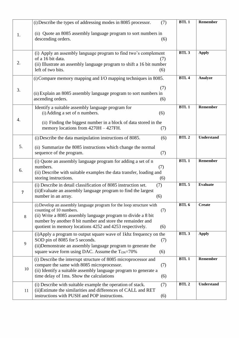
1.
(i) Describe the types of addressing modes in 8085 processor. (7)
(ii) Quote an 8085 assembly language program to sort numbers in
descending orders. (6)
BTL 1 Remember
2.
(i) Apply an assembly language program to find two’s complement
of a 16 bit data. (7)
(ii) Illustrate an assembly language program to shift a 16 bit number
left of two bits. (6)
BTL 3 Apply
3.
(i) Compare memory mapping and I/O mapping techniques in 8085.
(7)
(ii) Explain an 8085 assembly language program to sort numbers in
ascending orders. (6)
BTL 4 Analyze
4.
Identify a suitable assembly language program for (i) Adding a set of n numbers. (6)
(ii) Finding the biggest number in a block of data stored in the
memory locations from 4270H – 427FH. (7)
BTL 1 Remember
5.
(i) Describe the data manipulation instructions of 8085. (6)
(ii) Summarize the 8085 instructions which change the normal
sequence of the program. (7)
BTL 2 Understand
6.
(i) Quote an assembly language program for adding a set of n
numbers. (7)
(ii) Describe with suitable examples the data transfer, loading and
storing instructions. (6)
BTL 1 Remember
7
(i) Describe in detail classification of 8085 instruction set. (7)
(ii)Evaluate an assembly language program to find the largest
number in an array. (6)
BTL 5 Evaluate
8
(i) Develop an assembly language program for the loop structure with
counting of 10 numbers. (7)
(ii) Write a 8085 assembly language program to divide a 8 bit
number by another 8 bit number and store the remainder and
quotient in memory locations 4252 and 4253 respectively. (6)
BTL 6 Create
9
(i)Apply a program to output square wave of 1khz frequency on the
SOD pin of 8085 for 5 seconds. (7)
(ii)Demonstrate an assembly language program to generate the
square wave form using DAC. Assume the TON=70% (6)
BTL 3 Apply
10
(i) Describe the interrupt structure of 8085 microprocessor and
compare the same with 8085 microprocessor. (7)
(ii) Identify a suitable assembly language program to generate a
time delay of 1ms. Show the calculations (6)
BTL 1 Remember
11
(i) Describe with suitable example the operation of stack. (7)
(ii)Estimate the similarities and differences of CALL and RET
instructions with PUSH and POP instructions. (6)
BTL 2 Understand

12
(i) Describe with a suitable 8085 assembly language program the use
of subroutine instructions. (7)
(ii) Distinguish an assembly language program to generate Fibonacci
series using subroutines. (6)
BTL 2 Understand
13
Explain the operations carried out when 8085 executes the
instructions: (13)
(i)MOV A,M
(ii)XCHG
(iii)DAD B
(iv)LDA 6000
(v)SHLD 4000
BTL 4 Analyze
14
(i) Analyze a program to output square wave of 1KHz frequency on
the SOD pin of 8085 for 5 seconds. (7)
(ii) Explain an assembly language program to generate the square
wave form using DAC. Assume the TON=70% (6)
BTL 4 Analyze
PART-C
1.
Explain an 8085 assembly language program to solve the following
equation: Z=2X+Y where X and Y are stored in memory location
4200 and 4201 respectively. The value of Z should be stored in
4202 (Lower byte) and 4203(Lower byte). (15)
BTL 5 Evaluate
2.
(i)Develop a program to calculate and store in the results as
mentioned. Five memory locations 2401H, 2402H, 2403H, 2404H
and 2405H have data called X1,X2,X3,X4 and X5.
(2405H) = X1+X2+X3+X4
(2403H) = X5-X3-X2-X4 (15)
BTL 6 Create
3.
(i) Develop a suitable program for the below: Sixteen bytes are
stored in memory locations at XX50H to XX5FH. Transfer the
entire block of data to new memory locations starting at XX70H.
(8)
(ii) Compose an assembly language program based on 8085
microprocessor instruction set to search the smallest data in a set.
(7)
BTL 6 Create
4.
(i) Explain the loop structure with counting and indexing in 8085
programming. (8)
(ii) Write an 8085 program to count the number of even and odd
numbers in a given set of numbers. (7)
BTL 5 Evaluate
UNIT III- 8051 MICRO CONTROLLER
Hardware Architecture, pintouts – Functional Building Blocks of Processor – Memory organization –
I/O ports and data transfer concepts– Timing Diagram – Interrupts-Comparison to Programming
concepts with 8085.
PART - A
Q.No Questions BT Competence
1. Explain the operating mode 0 of 8051 ports BTL-4 Analyze
2. Discuss the function of TMOD register in 8051 microcontroller BTL-2 Understand
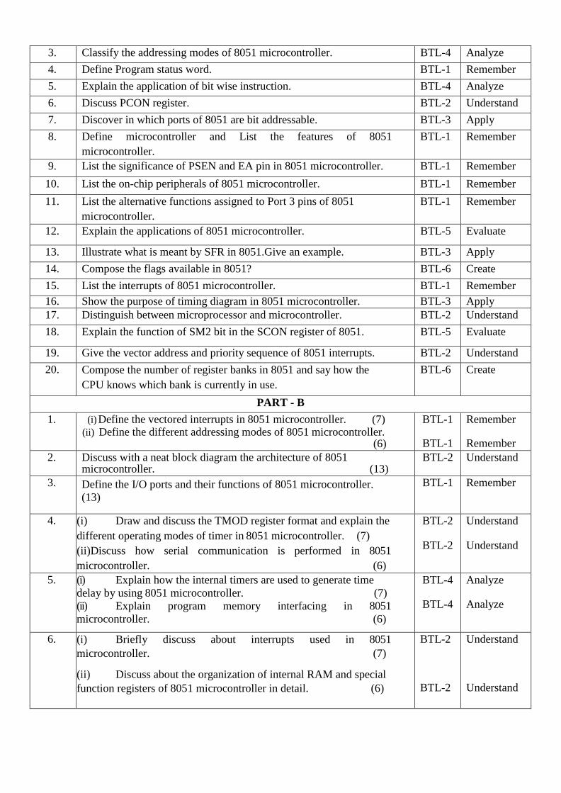
3. Classify the addressing modes of 8051 microcontroller. BTL-4 Analyze
4. Define Program status word. BTL-1 Remember
5. Explain the application of bit wise instruction. BTL-4 Analyze
6. Discuss PCON register. BTL-2 Understand
7. Discover in which ports of 8051 are bit addressable. BTL-3 Apply
8. Define microcontroller and List the features of 8051
microcontroller.
BTL-1 Remember
9. List the significance of PSEN and EA pin in 8051 microcontroller. BTL-1 Remember
10. List the on-chip peripherals of 8051 microcontroller. BTL-1 Remember
11. List the alternative functions assigned to Port 3 pins of 8051
microcontroller.
BTL-1 Remember
12. Explain the applications of 8051 microcontroller. BTL-5 Evaluate
13. Illustrate what is meant by SFR in 8051.Give an example. BTL-3 Apply
14. Compose the flags available in 8051? BTL-6 Create
15. List the interrupts of 8051 microcontroller. BTL-1 Remember
16. Show the purpose of timing diagram in 8051 microcontroller. BTL-3 Apply
17. Distinguish between microprocessor and microcontroller. BTL-2 Understand
18. Explain the function of SM2 bit in the SCON register of 8051. BTL-5 Evaluate
19. Give the vector address and priority sequence of 8051 interrupts. BTL-2 Understand
20. Compose the number of register banks in 8051 and say how the
CPU knows which bank is currently in use.
BTL-6 Create
PART - B
1. (i) Define the vectored interrupts in 8051 microcontroller. (7) (ii) Define the different addressing modes of 8051 microcontroller.
(6)
BTL-1
BTL-1
Remember
Remember
2. Discuss with a neat block diagram the architecture of 8051 microcontroller. (13)
BTL-2 Understand
3. Define the I/O ports and their functions of 8051 microcontroller.
(13)
BTL-1 Remember
4. (i) Draw and discuss the TMOD register format and explain the
different operating modes of timer in 8051 microcontroller. (7)
(ii)Discuss how serial communication is performed in 8051
microcontroller. (6)
BTL-2
BTL-2
Understand
Understand
5. (i) Explain how the internal timers are used to generate time
delay by using 8051 microcontroller. (7)
(ii) Explain program memory interfacing in 8051
microcontroller. (6)
BTL-4
BTL-4
Analyze
Analyze
6. (i) Briefly discuss about interrupts used in 8051
microcontroller. (7)
(ii) Discuss about the organization of internal RAM and special
function registers of 8051 microcontroller in detail. (6)
BTL-2
BTL-2
Understand
Understand

7. (i) Show the data memory structure of 8051 microcontroller
and explain. (7)
(ii) Illustrate with block diagram how to access external
memory devices in an 8051 based system. (6)
BTL-3
BTL-3
Apply
Apply
8. Explain in detail pin diagram of 8051 microcontroller. (13) BTL-5 Evaluate
9. (i) Explain Timing diagram interrupt structure of 8051 in detail.
(7)
(ii) Explain the program and data memory structure of 8051
microcontroller. (6)
BTL-4
BTL-4
Analyze
Analyze
10. Compose the signal configuration of 8051 and explain the purpose
of each signal. (13)
BTL-6 Create
11. (i) Describe in detail the different methods of memory address
decoding in 8051. (7)
(ii) Describe the operation of stack in 8051. (6)
BTL-1
BTL-1
Remember
Remember
12. Define the Timers of 8051 microcontroller with relevant diagrams.
(13)
BTL-1 Remember
13. Explain in detail, the hardware and software support provided by
8051 for serial communication. (13)
BTL-4 Analyze
14. Briefly illustrate the internal port structure of 8051 microcontroller.
(13)
BTL-3 Apply
PART - C
1. (i) Explain the interrupt structure of 8051 microcontroller. (8) (ii) Explain the RAM structure of 8051 microcontroller (7)
BTL-4
BTL-4
Analyze
Analyze
2. Explain the different modes of operation by serial port in 8051 in
detail with its associated registers. (15)
BTL-4 Analyze
3. With suitable block diagram, explain the architecture of 8051
microcontroller. Also explain the function of each block. (15)
BTL-4 Analyze
4. (i) Prepare an 8051 assembly language program to multiply the given
number 48H and 30H. (8)
(ii) Compose the types of addressing mode with suitable example
in 8051. (7)
BTL-6 Create
UNIT IV- PERIPHERAL INTERFACING
Study on need, Architecture, configuration and interfacing, with ICs: 8255, 8259, 8254, 8237, 8251,
8279, - A/D and D/A converters &Interfacing with 8085& 8051.
PART - A
Q.No Questions BT Competenc
1. Compose the control word value for 8255 PPI when PORT A and
PORT B are inputs in simple I/O mode.
BTL-6 Create
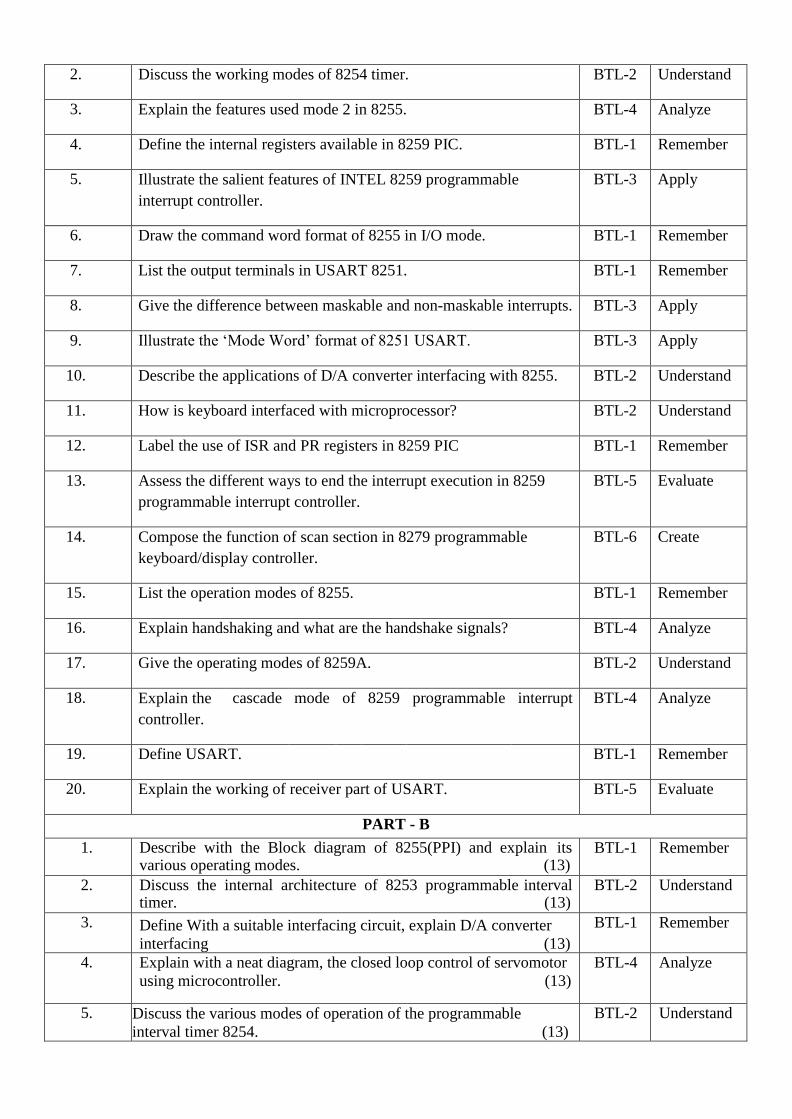
2. Discuss the working modes of 8254 timer. BTL-2 Understand
3. Explain the features used mode 2 in 8255. BTL-4 Analyze
4. Define the internal registers available in 8259 PIC. BTL-1 Remember
5. Illustrate the salient features of INTEL 8259 programmable
interrupt controller.
BTL-3 Apply
6. Draw the command word format of 8255 in I/O mode. BTL-1 Remember
7. List the output terminals in USART 8251. BTL-1 Remember
8. Give the difference between maskable and non-maskable interrupts. BTL-3 Apply
9. Illustrate the ‘Mode Word’ format of 8251 USART. BTL-3 Apply
10. Describe the applications of D/A converter interfacing with 8255. BTL-2 Understand
11. How is keyboard interfaced with microprocessor? BTL-2 Understand
12. Label the use of ISR and PR registers in 8259 PIC BTL-1 Remember
13. Assess the different ways to end the interrupt execution in 8259
programmable interrupt controller.
BTL-5 Evaluate
14. Compose the function of scan section in 8279 programmable
keyboard/display controller.
BTL-6 Create
15. List the operation modes of 8255. BTL-1 Remember
16. Explain handshaking and what are the handshake signals? BTL-4 Analyze
17. Give the operating modes of 8259A. BTL-2 Understand
18. Explain the
controller.
cascade mode of 8259 programmable interrupt BTL-4 Analyze
19. Define USART. BTL-1 Remember
20. Explain the working of receiver part of USART. BTL-5 Evaluate
PART - B
1. Describe with the Block diagram of 8255(PPI) and explain its various operating modes. (13)
BTL-1 Remember
2. Discuss the internal architecture of 8253 programmable interval timer. (13)
BTL-2 Understand
3. Define With a suitable interfacing circuit, explain D/A converter
interfacing (13)
BTL-1 Remember
4. Explain with a neat diagram, the closed loop control of servomotor
using microcontroller. (13)
BTL-4 Analyze
5. Discuss the various modes of operation of the programmable
interval timer 8254. (13)
BTL-2 Understand

6. i) Illustrate the control word of 8253 timer/counter and explain
the operation modes of 8253 timer/counter. (6)
ii) Examine why do we need A/D converter and D/A
Converter? Draw the block diagram to interface 8085
microprocessor with A/D converter and D/A convertor. (7)
BTL-3
BTL-3
Apply
Apply
7. Compose how 8279 keyboard and Display controller is interfaced to 8085 or 8051. (13)
BTL-6 Create
8. i) Describe the block diagram and modes of the 8254 timer. (7)
ii) Describe the architecture, functions and registers of the 8255
PPI. (6)
BTL-1
BTL-1
Remember
Remember
9. Describe with Block diagram of 8259(PIC) and explain the
initialization command words. (13)
BTL-2 Understand
10. Explain how the serial data transfer can be performed using 8251
USART. (13)
BTL-4 Analyze
11. Illustrate and draw the interfacing of A/D and D/A converter
interfacing to 8085 µp. (13)
BTL-3 Apply
12. (i) Explain the operation of 8255 PPI Port A programmed as input
and output in mode 1 with necessary handshaking signals. (7)
(ii) Explain the parallel communication between two processors
using mode 2 of 8255. (6)
BTL-4
BTL-4
Analyze
Analyze
13. Describe the architecture of DMA controller 8237. (13) BTL-1 Remember
14. Explain the seven segment LED interface with microprocessor.(13) BTL-5 Evaluate
PART - C
1. Explain the working of 8237 as a DMA controller and its command registers and their function. (15)
BTL-4 Analyze
2. Draw and explain the functional
communication interfacing chip.
diagram of parallel
(15)
BTL-4 Analyze
3. Explain the working of 8279 as a keyboard/display controller and
explain its command registers and their functions. (15)
BTL-4 Analyze
4. Compose the ADC and DAC interface with 8085 & 8051. (15) BTL-6 Create
UNIT V- MICRO CONTROLLER PROGRAMMING & APPLICATIONS
Data Transfer, Manipulation, Control Algorithms& I/O instructions – Simple programming
exercises- key board and display interface – Closed loop control of servo motor- stepper motor
control – Washing Machine Control.
PART - A
Q.No Questions BT Competenc

1. Define program status word. BTL-1 Remember
2. State and explain the functions performed by JBC and CJNE
instructions in 8051 microcontroller
BTL-4 Analyze
3. What is duty cycle in PWM? BTL-2 Understand
4. Discuss about CALL statement in 8051 BTL-2 Understand
5. Explain what is meant by PSW. BTL-4 Analyze
6. List out the difference between MOV and MOVX instructions BTL-1 Remember
7. What is baud rate? BTL-2 Understand
8. Evaluate the control signals from 8051 microcontroller required for
washing machine control?
BTL-5 Evaluate
9. Discuss how is pulse generated from microcontroller for stepper
motor control.
BTL-2 Understand
10. Show why do we need opto-isolator circuit between
microcontroller and the stepper motor?
BTL-3 Apply
11. Define the operation of the given 8051 microcontroller instructions:
XRL A, direct.
BTL-1 Remember
12. Compose the I/O related instructions in microcontroller 8051. BTL-6 Create
13. List the different types of 8051 instructions. BTL-1 Remember
14. List the addressing modes supported by 8051. BTL-1 Remember
15. Show how can you perform multiplication instructions in
microcontroller 8051?
BTL-3 Apply
16. Illustrate 8051 program to divide two 8-bit numbers. BTL-3 Apply
17. Name the addressing mode followed in the following instructions:
MOV R1,#02H and MOV R1,2
BTL-1 Remember
18. Explain the instructions :LJMP and SJMP BTL-4 Analyze
19. Assess how 8051 differentiates between the external and internal
program memory.
BTL-5 Evaluate
20. Compose how the DIV AB instruction works in an 8051
microcontroller?
BTL-6 Create
PART - B
1. Describe the control system design of washing machine (13) BTL-1 Remember
2. Describe with a neat diagram the stepper motor control using microcontroller. (13)
BTL-1 Remember
3. Explain with a neat diagram the closed loop control of servomotor
using microcontroller. (13)
BTL-4 Analyze
4. Discuss how to interface a 4 x 4 matrix keyboard using 8051
microcontroller and explain how to identify the key press. (13)
BTL-2 Understand
5. i) Compose the stepper motor control using 8051. (7)
ii) Compose a program to generate pulse to drive and for
continuous operation of a stepper motor. (6)
BTL-6
BTL-6
Create
Create
6. Explain the various types of instruction set used in 8051
microcontroller. (13)
BTL-4 Analyze
7. Draw and discuss the circuit diagram to interface an LCD display with 8051 microcontroller and explain how to display a character
using LCD display. (13)
BTL-2 Understand
8. Explain with a neat diagram the application of 8051
microcontroller in washing machine control. (13)
BTL-4 Analyze
9. Describe with a program to rotate the stepper motor in both
clockwise direction using 8051 microcontroller. (13)
BTL-1 Remember
10. List the different types of instructions set used in 8051
microcontroller. (13)
BTL-1 Remember
11. Illustrate an assembly language program based on 8051
microcontroller instruction set to perform four arithmetic
operations on two 8 bit data. (13)
BTL-3 Apply
12. Contrast a program to generate pulses to derive and for continuous
operation of a stepper motor. (13)
BTL-2 Understand
13. Explain about various types of jump instructions according to
range.(13)
BTL-5 Evaluate
14. i) Illustrate an 8051 assembly language program to copy 10
bytes of data stored from location 30H to another location starting
from 50H. (7)
(ii)Show with a neat diagram the stepper motor control using 8051
microcontroller. (6)
BTL-3
BTL-3
Apply
Apply
PART - C
1. Explain the stepper motor control using 8051 and write an
assembly language program for running the stepper motor in clockwise direction. (15)
BTL-4 Analyze
2. Design the closed loop control of a servo motor using 8051 with a
neat diagram. (15)
BTL-6 Create
3. Explain the washing machine control using 8051 and write a
program for the same. (15)
BTL-4 Analyze
4. Explain the interfacing of four digit 7 segment display to 8051 and
its program. (15)
BTL-4 Analyze


![Opcode 어셈명령으로 변환하기index-of.co.uk/Reverse-Engineering/opcode-[CodeEngn].pdf · 2019-03-07 · 다음은 W32Dasm 디어셈블 모습 여기까지 서로 다른 모습의](https://img.dokumen.tips/doc/110x75/5f105b2c7e708231d448b475/opcode-eeoeeoe-eeindex-ofcoukreverse-engineeringopcode-codeengnpdf.jpg)


