Embed Size (px)
Citation preview

Department of Defense US ARMY SBIR Program
Cross-Layer Designs for Energy-Efficient Sensor Networking
Phase I Final Technical Report
CLIN: 0002 Final Technical Report
Contract Number: W911QX-04-C-0042
Contract Dollar Amount $69,992.11
Competitive Award
Sponsored by:
US ARMY Research Laboratories
2800 Powder Mill road, Adelphi MD, 20783-1197
Attn: [email protected] Dr. Ananthram Swami
Prepared by:
Howard R. Stevenson Jr. David J. Schroeder Stuart W. Card
Critical Technologies Inc.
Suite 400 Technology Center, 4th Floor 1001 Broad Street, Utica NY 13501
315-793-0248 / FAX -9710 http://www.critical.com

Critical Technologies Inc. Contract:: W911QX-04-C-0042 Topic Title: Cross-Layer Designs for Energy-Efficient Sensor Networking Final Technical Report
Page 1
1 Results of the Phase I Work In accordance with the Phase I solicitation, CTI and Cornell University proposed and analyzed novel cross-layer design techniques leading to robust scalable architectures for sensor networks, operating under varying system loads. Cornell has analyzed the computation complexity and bandwidth efficiency of the Opportunistic Aloha (O-Aloha) Medium Access Control (MAC) protocol and the Sensor Network with Mobile Access (SENMA) concept of operations versus traditional multi-hop routed ad hoc networks. CTI has analyzed the implementation complexity of measuring range as a by-product of communication and deriving position from responses to a maneuvering interrogator versus computing range from Global Positioning System (GPS) fixes. The team has addressed the main robustness and scalability issue of collisions on uplink transmissions from the many nodes of the assumed dense sensor field. Cornell has shown feasibility via quantitative mathematical analysis rather than simulation. With hardware development assistance from CTI and funding from non-SBIR sources, Cornell is preparing to further demonstrate feasibility with software implementing the protocols on acoustic, rather than radio frequency (RF) hardware nodes. Selected audio carrier frequencies, at the lower propagation velocity of sound versus RF, yields wavelengths, and therefore range accuracies, comparable to those expected from future radio implementations. For each Phase I objective, the research conducted, findings reached and resulting estimates of technical feasibility follow.
1.1 Base Effort Per the solicitation, Army Future Combat Systems (FCS) envisage deployment of large scale sensor networks to provide timely and reliable information to warfighters. These peer-to-peer (P2P) wireless networks face challenges: mobility, uncertain terrain/channel conditions, scalability and severe bandwidth and energy constraints. Links will be asymmetric, users will be asynchronous, sensors may be duty-cycled and network load may vary widely. Traditional TDMA or CSMA/CA protocols plus separate network, MAC & physical layer (PHY) designs will be inadequate. Cross-layer designs will yield robust low-complexity transceivers that cope with time- and frequency-selective channels, undesired interference and noise. To these PHY concerns, in Phase I proposal development, CTI added support for Delay/Disruption Tolerant Networking (DTN, where networks are only intermittently connected), Emissions Control (EMCON), Low Probability of Detection (LPD), Low Probability of Interception (LPI), spectrum re-use and interference mitigation. Most important is the requirement that sensor readings be tagged accurately with the space-time locations where they were taken. Position, or at least interrogator to sensor node range, can also be used to optimize real-time MAC performance. These requirements drive the PHY selection and cross-layer design.
1.1.1 Channel Characteristics of UWB Sensors The Phase I proposal identified Ultra-WideBand (UWB) as the optimal PHY to meet these requirements. In response to concerns raised by Army Research Laboratory (ARL) personnel at the Phase I kickoff meeting, the assumption of Ultra-WideBand (UWB) as the physical layer was relaxed, to include Direct Sequence Spread Spectrum (DSSS) and other modulations and codings potentially capable of providing the desired range accuracy. Link budget analyses were performed for UWB and similar “Very Wide Band” (VWB) transmissions, showing that 1-kilometer slant ranges are achievable by pushing the range limits of UWB satisfying the current Federal Communications Commission (FCC) spectral mask. VWB communications would be easier to implement, and provide greater noise margins at the range limits, but obtaining spectrum for them likely would be problematic. Variations on the UWB concept have been identified: the original “impulse radio” approach; the newer Multi-Band OFDM Alliance (MBOA) approach, which is DSSS-like; and Engenium Technologies Corp’s very high slew rate, very wide span, modulated chirp, implemented in ETC’s ‘Flexceiver’ Software Defined Radio (SDR, see Attachment B). The feasibility of achieving adequate data rates, at ranges required to reach Unmanned Aerial Vehicle (UAV) interrogator platforms, measuring range (as a by-product of communication) to accuracies better than GPS, has been verified. Results of Phase I of the DARPA NETEX program confirm our findings regarding aggressively achievable UWB data rates, ranges and accuracies, as well as which scenarios do or do not engender mutual interference with narrowband radio services.

Critical Technologies Inc. Contract:: W911QX-04-C-0042 Topic Title: Cross-Layer Designs for Energy-Efficient Sensor Networking Final Technical Report
Page 2
Most concerns regarding interference to or from UWB derive from the original “impulse radio” concept: subsequent approaches, such as MBOA, address and significantly ameliorate these concerns; plus we have confirmed that VWB, provided spectrum is available, can meet the requirements, so PHY achievability is not a significant technical risk (see Attachment A). To minimize power consumption while the sensor node is sleeping, a narrowband receiver is indicated. However, to achieve range accuracy, a wideband receiver is indicated. The possibility has been considered of incorporating both, with the former running continuously or frequently, awakening the latter only when needed to accurately determine the time of arrival of the trigger pulse (and possibly to receive complex queries) from the interrogator. Minimization of size, weight and power (SWAP) requirements, as well as cost, is the major theme of the joint design, which should be able to achieve significant reductions versus traditional separate designs. SWAP, cost reduction and other benefits of cross-layer design are evident in results of recent efforts, such as the enormously successful Institute of Electrical and Electronics Engineers (IEEE) 802.11 wireless local area network (LAN) standard. The joint design was also considered in rendering a sensor fabric that is amenable to implementation and robust to reasonable environmental variations (channel, users, interferers, etc.). Variation in sensor types, flexibility in network architecture and application dependent operation led to the identification of the following classes of wireless sensor network nodes –
Heavy-weight Includes SENMA’s roaming interrogators and fixed or drifting hierarchical cluster heads Long-range links, MANET, full IP suite, non-volatile mass storage & Delay Tolerant Networking Accurate determination of absolute location (GPS, INS, etc.)
Medium-weight Minimally IPv6-capable short-range links Accurate timing -> range calculations in the sensor nodes (like AetherWire localizers) or Accurate timing -> range calculations in the interrogator (SENMA asymmetric design) or Fixed MAC address -> location looked up in a database populated upon emplacement or Transmitted coordinates -> location programmed into sensor node upon emplacement
Light-weight Minimal digital processing (no general purpose CPU) RFID tag style query-response (no general purpose protocols) Fixed response time -> range calculations in the interrogator (SENMA asymmetric design) or Node ID -> location looked up in a database populated upon emplacement Far-out idea: ultra-light-weight, all-analog nodes?
As the above indicates, noting the location at which sensors are emplaced obviates the need for calculating range (and position) from accurate timing or fixed response time in the sensor nodes. However, in the general case, sensors are not emplaced in known locations, and it is this general case that we addressed. Also apparent above are the alternatives for performing such calculations: in all the sensor nodes themselves (AetherWire’s localizers); or only on board the interrogators (the SENMA concept). The latter approach allows for consolidating complexity and cost asymmetrically in the smaller number of interrogators, which are less vulnerable than the sensors and more likely to be re-used over a longer operating life. The sensor network architecture will support all of these permutations, but the PHY, MAC and cross-layer sensor node design focused on the general (not emplaced in known locations), asymmetric (lower cost) case.

Critical Technologies Inc. Contract:: W911QX-04-C-0042 Topic Title: Cross-Layer Designs for Energy-Efficient Sensor Networking Final Technical Report
Page 3
1.1.2 Location Aware O-Aloha MAC During Phase I, we have focused on design of medium access control strategy of Sensor Networks with Mobile Access (SENMA) as illustrated in Fig. 1. We have proposed the use of Opportunistic Aloha (O-Aloha) as the baseline MAC scheme not only because the simplicity and the distributed nature of the protocol, but also because the use of channel state information enables the opportunistic transmission and the exploitation of multi-user diversity. We have three main objectives. First, we need to generalize O-Aloha to incorporate location information, which requires the derivation of transmission probability as a function or either the realization of sensor location or the prior distribution of the sensor location. Second, we aim to quantify the impact of implementation constraints on the throughput performance. Third, we have spent considerable effort in the implementation of acoustic SENMA from which we gained insights and guidance in real implementations.
Fig. 1. Sensor Network with Mobile Access
A direct benefit of SENMA is its scalability. SENMA does not maintain connections among sensors and focuses for the most part on one-hop transmissions between sensor nodes and mobile agents. The overhead of a large ad hoc network, in contrast, can be staggering. The size of the network and the power constraint on sensors make it impractical, if not impossible, to rely on sensors to organize the medium access control, to discover and maintain routes, to store and relay packets, to encode and decode. In addition to communication overhead, there is also a substantial but less quantified storage overhead. In the ad hoc architecture, to route packets through the network, buffers of sufficient size must be implemented at sensor nodes. Before reaching the final destination, packets stay in buffers at various locations of the network. The low duty cycle of the network prolongs the time packets stay in buffers, which makes it necessary to equip sensors with large memory cells. A less obvious argument for SENMA is its energy efficiency, a central concern to the topic. Indeed, energy efficiency is the chief reason that the multi-hop ad hoc architecture that relays packets in short distances is favored over the one-hop network with fixed access points or gateway nodes. For SENMA, one may question whether it is realistic to rely on low power sensors to reach mobile agents afar. The answer to this crucial question is affirmative, but it requires a careful analysis of energy efficiency and its scaling behavior as presented in [6]. It also requires the design of energy efficient schemes [3-5,7] that allow the transmission to mobile agents at a distance that normally would not have been reachable. The key is to trade the size of the network for power efficiency by exploiting multi-user diversity via opportunistic transmissions, an idea that has been proposed in an information theoretic setting.
Critical Technologies Inc. Contract:: W911QX-04-C-0042 Topic Title: Cross-Layer Designs for Energy-Efficient Sensor Networking Final Technical Report
Page 4
1.1.2.1 Opportunistic ALOHA for UWB Sensor Networks: A Cross Layer Design
In any multiaccess system, centralized scheduling provides the highest network throughput. In SENMA, centralized scheduling would mean that the mobile agent is able to address each sensor individually and is aware of the channel between itself and the sensor. The complexity of such schemes is unacceptable for large networks. A more practical choice, although in general suboptimal, is distributed medium access where each sensor schedules its transmission locally. The design of distributed access protocol for SENMA, however, is nontrivial. The large number of sensor nodes, the lack of central control, the channel fading, and node duty cycle, all make the design especially challenging. The multiaccess protocol for SENMA should have the following properties.
1. The protocol should be easy to implement. Each node should involve minimal processing and rely as little as possible on feedback;
2. The protocol should have high throughput and high efficiency in channel utilization. While the data rate from each sensor is low, the time allowed for the mobile agent to collect data can be constrained, especially in military applications.;
3. The protocol must be power efficient. For large-scale sensor networks, battery operated sensors have limited power and range. It is therefore necessary that sensors transmit only under favorable fading conditions.
In this project, we propose a general form of distributed access, referred to as Opportunistic ALOHA (O-ALOHA), that incorporates channel state information. Specifically, each sensor transmits a packet with a probability s(γ) as a function of its own channel state γ. The transmission control s(γ) is chosen to optimize the network throughput.
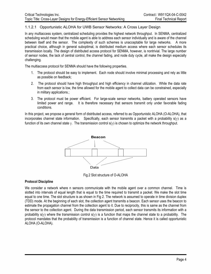
Fig.2 Slot structure of O-ALOHA
Protocol Discipline We consider a network where n sensors communicate with the mobile agent over a common channel. Time is slotted into intervals of equal length that is equal to the time required to transmit a packet. We make the slot time equal to one time. The slot structure is as shown in Fig 2. The network is assumed to operate in time division duplex (TDD) mode. At the beginning of each slot, the collection agent transmits a beacon. Each sensor uses the beacon to estimate the propagation channel from the collection agent to it. Due to reciprocity, this is same as the channel from the sensor to the collection agent. During the data transmission period, each sensor transmits its information with a probability s(γ) where the transmission control s(γ) is a function that maps the channel state to a probability. The protocol mandates that the probability of transmission is a function of channel state. Hence it is called opportunistic ALOHA (O-ALOHA).

Critical Technologies Inc. Contract:: W911QX-04-C-0042 Topic Title: Cross-Layer Designs for Energy-Efficient Sensor Networking Final Technical Report
Page 5
O-ALOHA Random Access We propose to investigate different transmission controls that demonstrate good performance for the physical layer under consideration. The effect of transmission control is two fold. It can be used to regulate interference by controlling the average number of transmitting sensors. Also, when the transmission control can depend on the channel state, it can also be used to change the aposteriori channel state distribution (distribution of channel state conditioned on the event that a sensor transmitted). If f(γ) is the apriori probability density function of the channel state and g(γ) is the target probability density function of the channel state, a transmission control that can be used to asymptotically (in the number of users) change the channel state distribution to g(γ) is:
where n is the size of the network and x (a design parameter) is the average number of transmissions in a slot. For the PHY layer under consideration, it was shown that good target pdf are distributions with a roll-off. Any pdf that is of the form
where 0 < δ < 1 is considered to a density function with a roll-off. The parameters of the density function are δ, γ0, and γ1. It is important to choose all of them judiciously for good performance. 1.1.2.2 O-ALOHA with UWB Sensors
We assume that the all the sensors are located in a disc of radius 1. As shown in Fig. 3, the collection agent is assumed to be a distance d above the center of the disc. Let ri be the radial distance of sensor i. We model ri as a random variable that is uniformly distributed between 0 and 1. The propagation channel gain between sensor i and the mobile agent is modeled as
where Rit is Rayleigh distributed. In addition, assume that Rit is independent and identically distributed between slots and sensors. We assume that the physical layer of the sensor network is a based on UWB senors. It is assumed that each sensor transmits episodic pulses with certain chip probability. The receiver at the mobile agent performs matched filtering. We assume that if the signal to interference ratio is greater than the threshold then the packet is received successfully. We use a threshold model for UWB sensors. Specifically, we will derive signal-to-interference and noise ratio (SINR) expressions as the function of the average number nodes, the episodic transmission probability, and noise variance. We will consider different fading models, especially Rayleigh and Rician fadings.

Critical Technologies Inc. Contract:: W911QX-04-C-0042 Topic Title: Cross-Layer Designs for Energy-Efficient Sensor Networking Final Technical Report
Page 6
Fig 3. SENMA with random sensor deployment
1.1.2.3 Incorporating Location Information in O-Aloha.
A key feature of UWB is its ability for geolocation. It is therefore possible to incorporate distance information between the sensor and the mobile agent into transmission control. In Location Aware Transmission Control (LAT), every sensor makes an estimate of its radial distance and the decision to transmit is a function of both the channel state γ and the location of the sensor r. The transmission control is chosen as
where f(γ|r) is the pdf of the channel state conditioned on the distance of the sensor. There is an alternative in which only the location statistics are used for the MAC protocol. By Location Independent Transmission Control (LIT), we mean that the transmission control is not dependent on the exact location, but only the distribution of the location parameter. In other words, if the location information r has a pdf g(.), then the transmission control is only a function of g(.). Assuming that the pdf of the channel state conditioned on the location r is given by f(γ), the LIT control can be written as
We have evaluated the performance of LAT and LIT protocols and find their performance comparable, and both showing considerable gain over O-ALOHA without location information. The significance of this result is that, for MAC throughput, the use of statistical information about geolocations may be sufficient.

Critical Technologies Inc. Contract:: W911QX-04-C-0042 Topic Title: Cross-Layer Designs for Energy-Efficient Sensor Networking Final Technical Report
Page 7
Figure 4: Comparing LAT and LIT O-ALOHA with O-ALOHA without location information.
1.1.2.4 Robustness and Sensitivity of O-ALOHA MAC
We have investigated robustness and sensitivities of O-ALOHA under various modeling errors. Specifically, we examined the effect of channel estimation error at the sensor node, the errors in the statistical model of channel states and locations, and network size. The network throughput is affected by these modeling errors but not in significant ways. For example, we found that instead of using exact network size in O-ALOHA, using the average network size leads no significant performance degradation.
Figure 5: O-ALOHA with mismatched channel states. We have also investigated the mismatch of uplink and downlink channel states. We do find that considerable loss is possible when the two channels have considerable mismatch. Thus a modification of O-ALOHA is needed. To this end, we consider the joint distribution of up and down link channel states as shown in Figure 5. We show that the optimal target transmission scheme is given by

Critical Technologies Inc. Contract:: W911QX-04-C-0042 Topic Title: Cross-Layer Designs for Energy-Efficient Sensor Networking Final Technical Report
Page 8
Such an integral equation is usually difficult to solve. However, under the additive mismatch model, i.e., the optimal target distribution satisfies a convolution form which can be solved in the frequency domain: where ΦT and ΦN are the moment generating functions of up and down link distributions. The impact of such optimal design, however, is still under investigation. 1.1.2.5 Acoustic SEMNA
Acoustic SENMA is an experimental system being implemented at Cornell University under the sponsorship of ONR-DURIP, ONR-MURI and ARL-CTA. Using acoustic sensors and acoustic medium, Acoustic SENMA captures fundamental features of sensor networks with mobile access, and it allows realistic tests of practical implementations. By leveraging support outside this SBIR project, we gain important insights into practical implementations for O-Aloha. During Phase I, we have spent considerable effort in the design and prototype of acoustic sensors with O-Aloha as its MAC. This effort results in the complete design of the acoustic sensor with four levels of channel quantization.
1.1.3 Sensor Density and Measurement Gradient The study of the sensor field properties of density and the gradient in relation to the generality of application is an optimization problem with an essentially unbounded feasibility region. An optimal solution is impractical where the required sensor density is directly a function of novelty in detection, and novelty can be multi-dimensional. It can be defined to be the absolute level or difference in neighboring values as well as the time and/or position of the detection. Therefore any given optimal solution requires more operations analysis and feedback to be meaningful. Items of interest and discussion included:
• Gradient models: Continuous; Hotspot and Discreet
• Positional Accuracy requirement for each model for rendering the gradient model meaningful
• Defining scenarios with highly correlated data best suited for O-Aloha of sensor interrogation Regardless of the lack of a generalization solution, the channel characterization task shows that position accuracies better than GPS are achievable, and the MAC protocol evaluation shows that O-Aloha is in certain applications optimal for very dense sensor fields. Therefore the proposed scheme is at least as good as conventional approaches. Position accuracies and communications ranges are comparable to those of IEEE 1451.5 and IEEE 802.15.4a. In future (non-SBIR) work, operations analysis software must be identified or developed to enable design of sensor distributions for particular application scenarios.

Critical Technologies Inc. Contract:: W911QX-04-C-0042 Topic Title: Cross-Layer Designs for Energy-Efficient Sensor Networking Final Technical Report
Page 9
1.1.4 Code Allocation Methods for Collision and Error Mitigation The main robustness and scalability issue in SENMA is that of collisions on uplink transmissions from the many nodes of the assumed dense sensor field, further corrupted by transmission channel errors. Potential approaches to mitigation of collisions and errors include Automatic Retransmission request (ARQ), Forward Error Correction (FEC) coding, their hybrids and various cross-layer coding schemes. ARQ is efficient over good links with few collisions; but has moderate buffer memory requirements and software complexity at both ends of the communications channel, contrary to the SENMA concept of concentrating complexity asymmetrically in the interrogators. FEC is better over poor links, reducing latency (and more importantly, latency variation) and increasing efficiency (indeed, turbo and low density parity check codes closely approach the Shannon limit); but hardware is required for fast decoding, and while FEC mitigates channel errors, it does little for collisions. Neither ARQ nor FEC is good over highly variable channels. Adaptive schemes are inherently hybrids, of which the most capable are adaptive Type II ARQ/FEC schemes, which can track the channel as it varies, staying close to the Shannon limit; but they are complex, and therefore recommended only for heavy- or possibly medium-weight sensor nodes. The dense sensor field allows for several “quick and dirty” approaches. Coding could be used not to attempt to correct, but merely to detect, errors, and sensor reports found to contain errors could merely be discarded. Even simpler, coding could be omitted, and errors detected instead on the basis of sensed quantities being outliers from the local statistical sample. It is conceivable that intentionally introducing errors into some sensor report transmissions might be used to mislead adversaries: mitigation opportunities are so rich that these artificial errors, compounding natural errors, could easily be tolerated. Vendor silicon implementing various IEEE standards likely could be used for inexpensive implementations. Combined coding and modulation was the original cross-layer communications design. It is a natural fit to high chip rate schemes, typical of UWB, but can be very compute-intensive. Due to the severe constraints on the sensor node, only moderate complexity uplink encoding and simple downlink decoding are recommended, unless vendor silicon appears that changes the economics of the situation. Combined coding and modulation is implicit in DSSS[-like] schemes, such as MBOA. In dense sensor networking, interesting joint source and channel coding options arise. In one trivial example, assume: simple scalar reports from sensors; transmissions perfectly synchronized; unipodal signaling (so that bit energies from different transmitters are additive at the receiver); and grey codes (so that similar sensed quantities will be represented by similar transmitted codewords). If collisions occur, most of the bits will remain decodable, and a coin can be flipped to determine those which are not, introducing negligible error! In a second trivial example, assume: fuzzy sensor reports in 7 classes corresponding to 7 spectral bands; transmissions unsynchronized; and unipodal signaling. Non-coherently integrate in the receiver to obtain a fuzzy sensor map!
1.1.5 Initial Phase II Prototype Specification & Design The initial design can be called a “Sensor Network Interface Card (SensorNIC)”. Just as an ordinary NIC connects a general purpose computer to a network, and handles arbitrary computer application data, a SensorNIC would connect a sensor node to a network, and handle arbitrary sensor data. If possible within SWAP and cost constraints, it should be interoperable with: IEEE 1451.0 and 1451.5 wireless sensor network standards; IEEE 802.15.4a wireless personal area network standards (Alt-PHY for precision location and extended range at low data rates); and the Internet Protocol suite (including IPv6). Its parameters should be tunable for specific applications. It should provide an industry-standard local wired interface to the rest of the sensor node (at least one sensor and possibly other subsystems such as local processing or storage): the tentative selection is the emerging “ExpressCard” standard; Universal Serial Bus (USB) 2.0 and optional high performance Peripheral Component Interconnect (PCI) Express (serial PCI-X) electrical and software interfaces are packaged in a very small form factor, hot swappable card. SENMA offloads responsibilities from the sensor node to the interrogator to enable dense sensor networking: the inexpensive SensorNIC would provide only those communications functions required in the sensor node; another, more costly, much lower volume version would provide the other terminus of communications, on the interrogator. Provision of robust, scalable sensor network services, despite the inherent unreliability of the sensors themselves, the communications channel over which their reports are transmitted, the storage media upon which received reports are accumulated, etc., is the ultimate goal of the system, of which the SensorNIC is the key enabling component.

Critical Technologies Inc. Contract:: W911QX-04-C-0042 Topic Title: Cross-Layer Designs for Energy-Efficient Sensor Networking Final Technical Report
Page 10
The following scenario has been verified as operationally realistic and technically feasible. A UAV interrogator cruises at 60 knots and 2000 feet altitude. Ground sensor node antenna radiation patterns are ideally hemispheric, with up to 3 decibels (dB) of gain, but actually fall somewhat short of that gain, and may be tilted up to 45 degrees from the normal due to the vagaries of mass deployment (probably air drop) to construct the dense sensor field. Sensor to interrogator look angle is limited to at least 45 degrees above the horizon. The radius of the patch illuminated by a single interrogation is therefore 2000 feet, yielding a maximum slant range just under 1 kilometer (km) and a patch area of 0.45 square miles (1.2 square km). The maximum time over target (TOT) is for a sensor node directly overflown by the UAV, along a diameter of the circular patch (at the center of the patch at the moment when the UAV is directly over the sensor node); such a best case TOT is 40 seconds. Inscribing a square in the circular illuminated patch yields an area only 2/pi (64%) as large, or 0.29 square miles (0.74 square km), throughout which TOT is at least 28 seconds. We divide this square into a 10 x 10 grid of square cells with side length 283 feet (86 meters) and area of 1.8 acres (0.74 hectares). We assume an average sensor density of one node per cell, which is the outcome of assuming a 50% chance of an empty cell, a 50% chance of at least one sensor, if at least one sensor then a 50% relative chance of a second, etc. This normalizes the computations, which can easily be modified to reflect the effect of a denser, sparser or differently shaped distribution. Lower UAV altitudes increase Signal to Noise Ratio (SNR), decrease collisions and improve localization accuracy but decrease TOT. In the above scenario, if an interrogator ‘client’ used the Transmission Control Protocol (TCP) to conduct a minimal transaction with a sensor node ‘server’, 10 packets might need to be exchanged, of which the longest might be 1536 bytes long, yielding (under additional reasonable worst case assumptions) a required half-duplex data rate between interrogator and sensor node of 10 kbps. TCP is an extremely poor and unlikely choice of transport protocol for such an application and is not recommended; this analysis is merely to provide a worst case data rate requirement. The User Datagram Protocol (UDP) over IPv6 is a much more reasonable choice, but still quite heavyweight for a SENMA application; it would require only 1 kbps between the interrogator and each sensor. These calculations yield rates and ranges comparable to those of IEEE 1451.5 and 802.15.4a, at their extremes of low data rate and long range. In the above scenario, sensor nodes located at the centers of grid cells have slant range differences to the UAV interrogator of at least 33 feet (10 meters, corresponding approximately to position accuracy of inexpensive GPS receivers). This yields one-way propagation delay differences of at least 33 nanoseconds (nS). A UAV receiver timing to this accuracy would have a residual ambiguity of at most 12 indistinguishable grid cells (forming a crude circle nearly reaching the edges of the square grid inscribed within the larger circular illuminated patch). Disambiguation would require greater timing accuracy and/or other techniques, such as different transmit frequencies or Code Division Multiple Access (CDMA) codes. Obviously, sensor nodes may not be located at grid cell centers. Inconspicuous man-portable sensor nodes (with only quarter wave antennas) and position accuracy to hit man-sized targets dictate PHY center frequencies and bandwidths on the order of 500 MHz or preferably higher. Bandwidths of 500 MHz in the 3.1 – 10.6 GHz range satisfy the current FCC definition of UWB, providing unlicensed access to an enormous swath of spectrum, albeit at low average power spectral density. The SensorNIC design, outlined at a high level above, will be refined to support the scenario outlined above, in the remaining Phase I period of performance, the Option if and when exercised, and the Phase II if and when awarded.
1.2 Option Effort The base effort identified some unique partnering opportunities that could further advance the start of the art in UWB sensor networks. It is recommended that the stated objectives of the Phase I Option be revised to reflect the transition stated in the Phase II proposal which involves leveraging a large-scale UWB test bed by modifying its MAC software toolkit to incorporate an API for the LAT/LIT O-Aloha MAC. Advancing an API precludes the immediate need for the test bed hardware. It is expected that this software effort will consume the entirety of the Option Budget as proposed.

Critical Technologies Inc. Contract:: W911QX-04-C-0042 Topic Title: Cross-Layer Designs for Energy-Efficient Sensor Networking Final Technical Report
Page 11
2 Proposed Phase II Technical Objectives and Approach The overall objective, per the solicitation, is to develop cross-layer approaches to radio design for bandwidth- and energy-efficient, robust, scalable, wireless, ad hoc sensor network architectures. This will enhance operational capabilities and contribute to operating and support cost reduction, by efficiently utilizing scarce bandwidth. The Phase II objective, per the solicitation, is to develop working prototypes (2-3 interrogators and 100 sensor nodes) based on cross-layer protocols and demonstrate their performance in a real-time environment.
2.1 Program Management in support of Phase III Transition Phase III transition is an important program objective that must be addressed by program management in Phase II, although its completion will extend beyond then. CTI has program management systems and practices not typically found in businesses of our size, focused on timely satisfaction of customer requirements in support of productization. Early and frequent contact with ultimate users is the basis of our transition approach. This is a ‘technical’ objective in that those user contacts will enable refinement of operational, functional and interface requirements of the system.
2.2 Cross-layer Wireless Sensor Network Systems Engineering CTI, as the prime contractor, in consultation with Cornell University, as the developer of the protocols central to the system, will develop and document the cross-layer system design. A detailed design, that considers not only PHY and MAC, but also higher layer protocols and applications, is the primary objective of Phase II, and the basis for latter objectives. This design will be driven by the requirements captured in pursuit of the transition objective (2.1) above: it is not expected that it will be possible to extract from the users all the relevant requirements, as in practice that is rarely achieved; but those requirements that can be validated, or at least inferred with some confidence, will be addressed. Important aspects of this objective include: minimizing overall system SWAP, nonrecurring and recurring cost; maximizing overall system performance, interoperability and usability; ensuring reliable sensor network services despite inherently unreliable sensors, communications links, storage devices, etc.; and ensuring scalability to networks with multiple analysis workstations, data repositories and interrogators, and very many sensor nodes.
2.3 Opportunistic Aloha MAC Protocol, Algorithm & Software Development Phase II research at Cornell will focus primarily implementation issues of SENMA in both acoustic and RF settings. We believe that the availability of acoustic SENMA as an experimental testbed will benefit tremendously the implementation of RF SENMA. For example, algorithms developed for acoustic SENMA are amendable for RF SENMA and results cross-checked. O-Aloha is the central piece of the cross-layer system design (2.2), and the acoustic testbed will enable that design to be validated early, while the UWB or VWB radios are in development.
O-Aloha with Channel Quantization. In practical implementation, it is necessary to quantize channel measurements and derive optimal transmission probabilities accordingly. Specifically, we need to find the optimal quantization levels and quantization thresholds. A combination of numerical and analytical studies is needed. We will address the following design issues: (i) what is the impact of quantization on throughput and energy efficiency? (ii) if location information is to be used, what is the appropriate quantization strategy? (iii) should the quantization be predetermined or can it be made adaptive, allowing more accurate channel representation in some cases and coarse quantization in others? This investigation must be conducted under specific channel models.
O-Aloha under Channel Uncertainties. This work focuses on O-Aloha under the asymmetrical channel propagation model. Since it is likely that the downlink channel is likely narrowband and the uplink channel a much wider band, the design of optimal transmission probability needs to be reevaluated. Quantization issues again enter the design equations. We will consider approximate solutions to the integral equation that defines the optimal transmission control. Extensive simulations are needed.
O-Aloha with Priority Transmissions. In many applications, certain types of measurements are much more important than others. It is thus highly desirable to create a transmission protocol that will differentiate data according their priority. In other words, the probability of transmission should be not only a function of channel state

Critical Technologies Inc. Contract:: W911QX-04-C-0042 Topic Title: Cross-Layer Designs for Energy-Efficient Sensor Networking Final Technical Report
Page 12
but also a function of data priority. The design of O-Aloha with priority requires the analysis of asymmetry in which certain sensors are designed for higher throughput than others. A related concept is the so-called data censoring where each sensor examine its data and decide if it is worthy of transmission. Data censoring has been considered in data fusion for ideal medium access. We will consider extend those strategies for O-Aloha
Location Acquisition via Mobile AP. Acquiring location information at sensor is nontrivial. While it is not realistic to assume that each sensor is equipped with a GPS device, the presence of mobile AP provides an attractive option for sensor to acquire location from multiple beacons from the mobile access point. We will investigate algorithms and protocols that allow each sensor calculates its geolocation from broadcasts of the mobile AP assuming that the mobile AP has its own geolocation. We will consider distributed signal processing algorithms and derive performance bounds for the location estimators.
2.4 Wireless PHY Selection, Hardware Development & System Integration The central cross-layer design linkage is between the O-Aloha MAC (2.3) and the wireless PHY, which must be selected, developed (whether from scratch or by starting with a radio vendor offering) and integrated with the MAC to form the sensor network data link subsystem. In the Phase I proposal, Time Domain Corp. (TDC) was identified as the putative PHY supplier, given their interest in military markets, their willingness to strive for extended ranges, and their cooperative sharing of essential information. While TDC has done nothing to weaken their competitive position, alternatives have emerged that must be considered. AetherWire & Location is also generally interested in military markets and specifically interested in teaming with CTI on sensor networking opportunities, but is not willing at present to try to reach ranges in excess of 100 meters, which they regard as a distraction from their focus of building short range localizer networks. Engenium Technologies Corp. (ETC) has prototypes of a UWB-capable SDR, which they call a ‘Flexceiver’: it uses a relatively conventional chirp waveform, but sweeps at a very high slew rate over a very wide span (their objective is 1 GHz in 1 millisecond); they claim to be able to achieve ranges far in excess of the 1 km required in this application. If their OSD-funded and AFRL/IF-managed effort goes to Phase II, they will build a testbed of 100 Flexceiver nodes, to which they are willing (if their sponsor approves) to grant us access (see 0 letter of intent). As their Government program manager is at AFRL/IF, 30 minutes away by car from CTI, and is an organization with which we have a longstanding close relationship, we regard sponsor approval as very likely. The MBOA variant of UWB should soon have inexpensive mass-market silicon support from several major vendors. Alternatives not only to specific UWB technologies and vendors, but to UWB in general, have also been considered: “Very Wide Band” (VWB) approaches can easily meet all requirements other than unlicensed spectrum availability. Selection of a PHY approach, technology and vendor, acquisition and/or development of PHY hardware, and integration of PHY with MAC as verified by laboratory demonstration, comprise the second major Phase II objective. As development of the preferred UWB PHY is leading edge, and Cornell has a surrogate acoustic testbed, efforts to accomplish this objective will lag those relating to MAC protocol development and validation. The Cost Proposal allocates a small but important fraction of Phase II funding to PHY acquisition, and many hours to integration.
2.5 UAV Selection, Platform Integration & SENMA Demonstration The proof of the SENMA concept, O-Aloha MAC (2.3), UWB or other PHY (2.4), and cross-layer sensor networking system (2.2), will be its demonstration in a testbed of 2-3 interrogators and 100 sensor nodes. At least one of the interrogators should be a UAV, while another 1-2 can be land mobile platforms or fixed heavyweight ground nodes acting as hierarchical cluster heads. The scenario outlined above (1.1.5) to support the design was based on the inexpensive “Silver Fox” small UAV from Advanced Ceramics Research (ACR) in Tucson AZ, another successful SBIR contractor. ACR has expressed serious interest in teaming with CTI to network their UAVs and use them as wireless network relays. While they are not yet formally committed to supporting the proposed effort, it is highly likely they will be willing to do so, given their interest in UAV network systems, and the allocation in the Cost Proposal of a small but significant fraction of the Phase II funding to acquiring one of their UAVs (or at least time on one). Should ACR prove unwilling to cooperate, or their UAV prove a poor match for SENMA test and demonstration, other relatively inexpensive small UAVs are becoming available. Empirical validation of location aware SENMA with range optimized O-Aloha over a PHY that provides range as a by-product of communication, with a real UAV as an interrogator and a number of sensor nodes that shows scalability, is the final objective of Phase II.

Critical Technologies Inc. Contract:: W911QX-04-C-0042 Topic Title: Cross-Layer Designs for Energy-Efficient Sensor Networking Final Technical Report
Page 13
3 Relationship with Future Research & Development
3.1 Anticipated Results of Phase I The successful result of the Phase I effort is the viability of the proposed UWB sensor within the SENMA architecture whereby bandwidth and power are conserved. The innovative cross-layer design approach provides a highly robust, low power, scalable sensor network that can be polled at the direction and discretion of the controlling agency with limited visibility by adversarial agents. The mutual non-interfering nature of the communication design is essential for multi-force interoperability. The Phase II prototype effort described will ultimately demonstrate its effectiveness.
3.2 Phase I as Foundation for Phase II Phase I captured the requirements, identified the available and selected the appropriate enabling technologies, and developed a preliminary design, of a prototype to be integrated, tested and demonstrated in Phase II. Unfortunately, the Phase I objective to identify potential users, effective uses, likely environments and operational constraints did not produce any early adoptors and supports. This effort must be redouble for a successful Phase III transition.
3.3 Phase II as Foundation for COTS Products The Phase II end result will be a demonstrated prototype, with reports outlining its costs and risks versus features and benefits. The Phase II proof-of-concept prototype is not only scalable, but is readily adapted to most sensor applications of interest, which can vary considerably based on expressed operational objectives. With the collaboration of a UAV manufacturer, we expect heightened interest in the demonstrations. This novelty and the abstraction of the sensor interface will promote interest in rapid productization of the Sensor Network Interface Card into COTS sensors. The Phase II program plan concludes with a design that is mature enough to commercialize for both military and commercial customers. CTI will market the S-NIC design directly to sensor manufacturers, thereby driving their focus of next generation products, rather than CTI attempting to enter the sensor market itself.
4 Related and Future Work The use of UWB transmission for sensor networks provides valuable location information that is crucial not only for energy efficient MAC but also for routing. To this end, we have recently developed adaptive routing schemes based on geolocations [9]. Currently, we are investigating the effect of UWB transmission parameter on throughput and delay characteristics. By using the episodic parameter of the direct sequence UWB waveform [10], we plan to develop a cross layer approach to MAC as well as routing for large scale sensor networks.

Critical Technologies Inc. Contract:: W911QX-04-C-0042 Topic Title: Cross-Layer Designs for Energy-Efficient Sensor Networking Final Technical Report
Page 14
REFERENCES: [1] P.Marshall, “DARPA Advanced Technology Office Connectionless Networking Program,” March, 2003. http://www.darpa.mil/ato/solicit/CN/c_brief.pdf. [2] J. Akyildiz, W. Su, Y. Sankarasubramaniam, and E. Cayirci, “A Survey on Sensor Networks,'' IEEE Communications Magazine, vol. 40, pp. 102--114, August 2002. [3] L. Tong, Q. Zhao, and S. Adireddy, ``Sensor Networks with Mobile Agents,'' Proc. 2003 MILCOM, Oct. 2003. [4] P. Venkitasubramaniam, S. Adireddy, and L. Tong, “Opportunistic ALOHA and Cross Layer Design for Sensor Networks,” Proc. 2003 MILCOM, Oct. 2003. [5] P. Venkitasubramaniam, S. Adireddy, and L. Tong, ``Sensor networks with mobile agents: Optimal random access and coding,'' July 2003, submitted to IEEE J. Select. Areas Comm.: Special Issue on Sensor Networks. [6] G. Mergen, Q. Zhao, and L. Tong, ``Sensor networks with mobile agents: Energy and Capacity Considerations,'' July 2003, submitted to IEEE J. Select. Areas Comm.: Special Issue on Sensor Networks. [7] S. Adireddy and L. Tong, ``Exploiting decentralized channel state information for random access,'' Submitted to IEEE Trans. Info. Theory, November, 2002. [8] S. Adireddy and L.Tong, ``Medium Access Control using Channel State Information for Large Sensor Networks,'' in Proceedings of the IEEE Workshop on Multimedia Signal Processing 2002, St. Thomas, US Virgin Islands, December 2002. [9] Q. Zhao and L. Tong, “Energy efficiency of ad hoc networks: An Analysis of Proactive, reactive and Hybrid Networking Strategies, ” submitted to IEEE INFOCOM, 2005, July, 2004. [10] B. Sadler and L. Tong, “On the performance of episodic UWB and Direct-Sequence Communication Systems,” to appear in IEEE Trans. Wireless Communications, 2005.

Critical Technologies Inc. Contract:: W911QX-04-C-0042 Topic Title: Cross-Layer Designs for Energy-Efficient Sensor Networking Final Technical Report
Attachment A-1
Proposed data communication links for the Energy Efficient Sensors.
There are two communication links needed to obtain data from a sensor field. The mobile access point Interrogation Downlink and the sensor Response Uplink.
Interrogation Downlink The proposed “downlink” interrogation from the mobile access point, which will be used to awaken and select the particular sensor(s) to start a data transmission, will use a relatively low frequency band and a narrow band transmission to take advantage of very simple receivers with low power consumption. Bands to be examined will be from VHF, starting at 50 MHz thru the 2.4 GHz band. The object is to keep the power consumption of the circuitry needed for this function to an absolute minimum. One possible system to be examined will be high power impulses to a tuned RF receiver. If possible the interrogation signal will be simply encoded to “wake up” classes or groups of sensors. In this case, as well as the Response Uplink case, the more complex, higher power consuming, and larger link equipment will be in the mobile access point, of which there are far fewer, rather than the sensors of which there are many and in some cases may be non-retrievable.
Response Uplink The proposed data “uplink”, first being looked at from the simple & low power sensors to the mobile access point(s), will use a “Very Wide Band” (VWB) waveform that uses the spectrum spreading technique of Ultra Wide Band (UWB) for energy efficiency with low probability of detection and intercept. The RF bandwidth of the signal will be controlled by using an impulse with a finite number of cycles at the carrier frequency and filtered to control excessive bandwidth . The pulse repetition rate will be adjusted for a low duty cycle and the data modulation will be such that the energy is spread over the RF bandwidth in a noise-like manner. The initial frequency considered was in the 1 GHz area but this choice, while tempting because of low losses giving better performance at lower powers, was discarded because of possible interference with services such as GPS and IFF. For example a better choice would be a 120 MHz RF bandwidth in the 3.2 GHz frequency range that would support data at a 100 KHz bit rate. The RF performance in terms of signal to noise verses range, power, and antenna gain performance is given a preliminary examination in the attached analysis.

Critical Technologies Inc. Contract:: W911QX-04-C-0042 Topic Title: Cross-Layer Designs for Energy-Efficient Sensor Networking Final Technical Report
Attachment A-2
Very Wide Band Communications Data Equations
23 February 2004 Howard R. Stevenson Jr. Critical Technologies Inc.
Communications Range and Noise Equations Path Loss in dB; From "Reference Data For Engineers" 7th Edition Howard W. Sams Inc
Chapter 33 pg 20 For: Pt/Pr (Power transmitted / Power received expressed in the same units),
f is frequency in mHz, d is the distance in miles, isotropic antennas are assumed; the formula for attenuation is:
Pt
Pr4.65 103
⋅ f 2⋅ d2
⋅:=
To convert d(miles) to d(kilometers), the constant 4.65 is divided by 1.6 2 (kilometers to the mile squared), becoming 1.7813 . This is constant one (c1). The most useful form of the equation is when all units are expressed in dB or in the case of power, dBm
c1 10 log4.56 103
⋅
1.6210,
⋅:= c1 32.507= dB
f 3200:= mHz cf 20 log f 10,( )⋅:= cf 70.103= dB
d 1:= km cd 20 log d 10,( )⋅:= cd 0= dB
Signal Power Level as a function of Range and Transmit Peak Power Signal Power Level: This is the solving of the Path Loss equation for Pr with the addition of antenna gains for both receive and transmit antenna gains (Gr, Gt). Because several transmit powers will be evaluated they become Pt1, Pt2, etc. Again the most useful form is when all units are expressed in dB and in the case of power, dBm. For Gr = 12 dB, Gt = 6 dB, Pt1 = 10 dBm, and a path loss of d1 = 102.61 dB at 1 km;
Pr Pt1 Gr+ Gt+ d1−:= Pr 74.61−= dBm

Critical Technologies Inc. Contract:: W911QX-04-C-0042 Topic Title: Cross-Layer Designs for Energy-Efficient Sensor Networking Final Technical Report
Attachment A-3
Very Wide Band Communications Data Equations (cont’d)
Receiver noise level as a function of noise figure and bandwidth Receiver Noise Level in dBm: From "Reference Data For Engineers" 7th Edition Howard W. Sams Inc
Chapter 34 pg 12 k is Boltzmann's constant: Te is effective noise temperature in degrees Kelvin: B is bandwidth in hertz Ni is effective input noise power: Ni = kBTe in Watts per Hertz For mWatts per Hertz add 30 dB, for mWatts per mHz add another 60 dB. Again, the most useful form of the equation is when all units are expressed in dB and in the case of power, dBm
k 10 log 1.38 10,( )⋅ 230− 30+:= (+ 30 converts to dBm instead of dBw, + 60 for dBm/mHz)
k 198.601−= Ni k 10 log 290( )⋅+ 60+:= Ni round Ni( ):= Ni 114−= dBm/MHz Receiver noise level (Npl) is the combination of Ni, receiver noise figure (Nf), and receiver bandwidth (BW). For a Noise BandWidth of 120 MHz and a 3.5 dB receiver noise figure:
Nf 3.5:= dB Nr Ni Nf+:= dBm/MHz
BW 10 log 120 10,( )⋅:= Npl Nr BW+:= Npl 89.708−= dBm Noise power leve
At 3200 MHz with a 120 MHz BandWidth; 2, 5, & 10 mw peak power levels, and a 3.5 dB noise figure:
0.1 0.2 0.3 0.4 0.5 0.6 0.7 0.8 0.9 1 1.1 1.2 1.3 1.4 1.5 1.6 1.7 1.8 1.993
90
87
84
81
78
75
72
69
66
63
60
57
54
51
Signal, 10 mwSignal, 5 mwSignal, 2 mwReceiver Noise Power
Signal Level vs Range
Range in km
Leve
l in
dBm
This graph shows the receiver signal and noise levels in dBm as a function of range and power.

Critical Technologies Inc. Contract:: W911QX-04-C-0042 Topic Title: Cross-Layer Designs for Energy-Efficient Sensor Networking Final Technical Report
Attachment A-4
Very Wide Band Communications Data Equations (cont’d)
At 3200 MHz with a 120 MHz BandWidth; 2, 5, & 10 mw peak power levels, and a 3.5 dB noise figure:
0.1 0.2 0.3 0.4 0.5 0.6 0.7 0.8 0.9 1 1.1 1.2 1.3 1.4 1.5 1.6 1.7 1.8 1.93
0
3
6
9
12
15
18
21
24
27
30
33
36
39
S\N, 10 mwS\N, 5 mwS\N, 2 mwS\N, 1 mwS/N, Zero dB
Signal to Noise Levels vs Range
Range in km
Sign
al to
Noi
se L
evel
s in
dB
This graph shows the receiver signal to noise ratio dB as a function of range and power.

Critical Technologies Inc. Contract:: W911QX-04-C-0042 Topic Title: Cross-Layer Designs for Energy-Efficient Sensor Networking Final Technical Report
Attachment B-1
Engenium Technologies Corp. – Letter of Intent
RT. 108 Suite 223 Columbia, MD 21043 Stuart W. Card Critical Technologies, Inc. Suite 400 Technology Center 4th Floor 1001 Broad St. Utica, NY 13501 Reference: Letter of intention to collaborate with Critical Technologies on a Phase II contract for ARL SBIR topic A03-035 “Cross-Layer Designs for Energy-Efficient Sensor Networking”. May 10, 2004 Dear Mr. Card, Engenium Technologies is pleased to announce its intention to collaborate with Critical Technologies on a potential Phase II contract for ARL SBIR topic A03-035 “Cross-Layer Designs for Energy-Efficient Sensor Networking”. If brought to fruition, Engenium would enter into a non-disclosure agreement with Critical Technology to enable the exchange of intellectual property. Engenium Technologies has products and experience relative to ARL SBIR topic A03-035 gained through Engenium contracts and the expertise of its employees in the areas of communications and networking. Specifically two Engenium products could be brought to bear, the FlexceiverTM and Ad Hoc Networking. Engenium Technologies has developed an ultra wideband (UWB) transceiver, called the Flexceiver, through sponsorship from the Navy and NSA. For the Navy application the Flexceiver is being developed as the foundation for a wireless network providing long-range communication capability (on the order of hundreds of miles). This software-defined radio can be configured to transmit and receive any of a variety of communications waveforms. The current prototype has a 150 MHz operational bandwidth with planned growth to 500 MHz. In a UWB mode the Flexceiver sweeps the carrier frequency very rapidly (1 terahertz/sec, or, 1 MHz/µs) across the bandwidth in a pseudo random fashion to construct frequency profiles that dynamically avoid interference with narrowband radio systems. Because the carrier sweep is generated digitally, flexible tailoring of the sweep profile is possible. While the operational bandwidth of the Flexceiver is wide, the instantaneous bandwidth of the receiver is narrow,

Critical Technologies Inc. Contract:: W911QX-04-C-0042 Topic Title: Cross-Layer Designs for Energy-Efficient Sensor Networking Final Technical Report
Attachment B-2
consistent with that of the rate and type of modulation. The swept UWB waveform results in a communications system that has LPD (low probability of detection), LPI (low probability of interception), and LPJ (low probability of jamming). The Flexceiver forces a jammer to spread its energy across the entire sweeping bandwidth and likewise forces an interceptor to receive the entire sweeping bandwidth because of the pseudo random nature of the rapidly swept carrier. Furthermore, by sweeping rapidly, individual multipath fades can be limited to a single bit duration or less. Forward error correction is employed to recover faded bits. This tolerance to multipath contributes to increased range performance of the Flexceiver by eliminating a fading allowance from the link budget. High data rate and long range are achieved via the use of coherent offset QPSK (OQPSK), which is among the best performing waveforms in terms of bits per sec/watt. The constant modulus of OQPSK affords the use of high power class C amplifiers, which eases the achievement of long range. In particular, the Flexceiver’s swept UWB is far superior to impulsive UWB, which has a high peak/average power ratio and therefore range limited. The receiver portion of the Flexceiver has extremely low latency resulting from rapid synchronization (on the order of twenty bit-periods) enabled by processing its preamble waveform to establish accurate frequency, phase, and symbol timing. An economical correlation algorithm for this waveform has been developed which is tolerant of unknown Doppler shifts. This permits rapid acquisition and successful communications between mobile operational units. The Flexceiver also features a self-organizing ad-hoc networking function. Engenium Technologies has worked on the development of algorithms and protocols for a wireless network of Flexceiver through a Phase I SBIR with OSD (topic number OSD03-026) entitled “Beyond Spectrum: Multi-Objective Joint Optimization for Efficient Utilization of the Radio Frequency Transmission Hypercube”. Engenium will shortly be submitting a proposal for development of a Phase II test bed of 100 networked Flexceivers, which with sponsorship permission/collaboration may be used for ARL SBIR topic A03-035. We hope that our innovative technologies can enhance your offering to ARL and we look forward to a potential mutually beneficial collaboration. If you have additional questions or concerns please do not hesitate to contact us. Sincerely,
Dr. Mike V. Pascale President


![Netex learningHub | Presentación [Es]](https://img.dokumen.tips/doc/110x75/541608698d7f72316c8b48f9/netex-learninghub-presentacion-es.jpg)
![Netex learningCloud | LearningMEX 2015 [ES]](https://img.dokumen.tips/doc/110x75/55a62efa1a28ab636d8b46e5/netex-learningcloud-learningmex-2015-es.jpg)
![Netex learningCoffee | Catalogue 2014 [En]](https://img.dokumen.tips/doc/110x75/541609598d7f722f6c8b491b/netex-learningcoffee-catalogue-2014-en.jpg)
![Netex learningCoffee | LearningMEX 2015 [ES]](https://img.dokumen.tips/doc/110x75/55a62efc1a28ab636d8b46e8/netex-learningcoffee-learningmex-2015-es.jpg)
![Netex learningCentral | Dossier [Es]](https://img.dokumen.tips/doc/110x75/5416081c8d7f72316c8b48f6/netex-learningcentral-dossier-es.jpg)
![Netex learningCloud 2018 [FR]](https://img.dokumen.tips/doc/110x75/5a64c62d7f8b9ac21c8b5c17/netex-learningcloud-2018-fr.jpg)
![Netex learningCoffee | Catálogo 2014 [Es]](https://img.dokumen.tips/doc/110x75/54444110b1af9f6c0a8b4806/netex-learningcoffee-catalogo-2014-es.jpg)
![Netex learningMaker | Presentación [Es]](https://img.dokumen.tips/doc/110x75/541607ef8d7f72316c8b48f4/netex-learningmaker-presentacion-es.jpg)
![Netex learningSocial | Presentation [EN]](https://img.dokumen.tips/doc/110x75/55b41436bb61ebef558b474a/netex-learningsocial-presentation-en.jpg)

![Netex learningApp | Presentation [En]](https://img.dokumen.tips/doc/110x75/5416085a8d7f722f6c8b4913/netex-learningapp-presentation-en.jpg)
![Netex learningSocial | Presentación [ES]](https://img.dokumen.tips/doc/110x75/55b414fdbb61ebe0558b4805/netex-learningsocial-presentacion-es.jpg)
![Netex learningMaker | Dossier [Es]](https://img.dokumen.tips/doc/110x75/541607df8d7f72316c8b48f3/netex-learningmaker-dossier-es.jpg)
![Netex learningApp | Presentación [Es]](https://img.dokumen.tips/doc/110x75/541608558d7f72336c8b493e/netex-learningapp-presentacion-es.jpg)
![Netex learningSocial | Presentazione [IT]](https://img.dokumen.tips/doc/110x75/55c3531ebb61eb8a4e8b4610/netex-learningsocial-presentazione-it.jpg)

![Netex | Gamification LT2016 [EN]](https://img.dokumen.tips/doc/110x75/58f037301a28ab9a578b456d/netex-gamification-lt2016-en.jpg)
![Netex learningHub | Presentation [En]](https://img.dokumen.tips/doc/110x75/541608178d7f72336c8b493b/netex-learninghub-presentation-en.jpg)
![Netex | Learning Stories [EN]](https://img.dokumen.tips/doc/110x75/5879b4d01a28ab6b2c8b6675/netex-learning-stories-en.jpg)
![Netex learningCentral | Presentation [En]](https://img.dokumen.tips/doc/110x75/541608458d7f72316c8b48f8/netex-learningcentral-presentation-en.jpg)

![Netex learningCentral | Dossier [En]](https://img.dokumen.tips/doc/110x75/5416082f8d7f72336c8b493c/netex-learningcentral-dossier-en.jpg)
![Netex learningMaker | Presentation [En]](https://img.dokumen.tips/doc/110x75/541608058d7f72316c8b48f5/netex-learningmaker-presentation-en.jpg)
![Netex learningCentral | Presentación [Es]](https://img.dokumen.tips/doc/110x75/541608318d7f72316c8b48f7/netex-learningcentral-presentacion-es.jpg)