Embed Size (px)
Citation preview
INCH-POUND
MIL-STD-398A 29 January 2014 SUPERSEDING MIL-STD-398 5 November 1976
DEPARTMENT OF DEFENSE DESIGN CRITERIA STANDARD
SHIELDS, OPERATIONAL FOR AMMUNITION OPERATIONS, CRITERIA FOR DESIGN OF AND TESTS FOR ACCEPTANCE
AMSC N/A FSC 4925 DISTRIBUTION STATEMENT A. Approved for public release; distribution is unlimited.
MIL-STD-398A, dated 29 January 2014, is hereby reinstated and may be used for acquisition.
Downloaded from http://www.everyspec.com
MIL-STD-398A
ii
FOREWORD 1. This military standard is approved for use by all Departments and Agencies of the Department of Defense (DoD). 2. This document does not constitute significant changes from the 6 November 1976 version of the MIL-STD. It reissues the canceled document. It also updates the thermal flux requirements, makes editorial corrections, and adds the Department of Defense Explosives Safety Board (DDESB) as the Agent for the Preparing Activity. 3 This standard defines the minimum criteria necessary to design an operational shield which will protect personnel and assets from thermal, pressure and fragmentation hazards resulting from an accidental or intentional detonation of ammunition or explosives; and identifies methods for testing prototype operational shields to assess the degree to which they meet the protection criteria specified. 4. Criteria identified in this standard are recognized as providing an environment that affords adequate protection for personnel and assets. 5. Comments, suggestions, or questions on this document should be addressed to: Commander, U.S. Army ARDEC, ATTN: RDAR-QES-E, Picatinny Arsenal, New Jersey 07806-5000 or e-mailed to [email protected]. Since contact information can change, you may want to verify the currency of this information using ASSIST Online database at https://assist.dla.mil/. Technical questions or recommended technical corrections, additions, or deletions should be addressed to the above Preparing Activity’s Agent;; Chairman, Department of Defense Explosives Safety Board (DDESB), 4800 Mark Center Drive Suite 16E12, Alexandria, VA 22350-3606. Phone: DSN 372-6747, Commercial (571) 372-6747; Fax (571) 372-6752, [email protected].
Downloaded from http://www.everyspec.com

MIL-STD-398A
iii
CONTENTS
Paragraph Page
FOREWORD .......................................................................................................... ii
1. SCOPE ........................................................................................................ 1 1.1 Scope ............................................................................................... 1 1.2 Application. ..................................................................................... 1
2. APPLICABLE DOCUMENTS .................................................................. 1 2.1 Issues of documents. ....................................................................... 1
3. DEFINITIONS ............................................................................................ 2 3.1 Deflagration .................................................................................... 2 3.2 Detonation ....................................................................................... 2 3.3 Dividing wall .................................................................................. 2 3.4 Maximum credible incident ............................................................ 2 3.5 Operating building .......................................................................... 2 3.6 Operational environment ................................................................ 2 3.7 Operational shield ........................................................................... 2 3.8 Peak positive incident pressure (Pso) ............................................. 2 3.9 Peak positive normal reflected pressure (Pr) .................................. 2 3.10 Simulated operational bay environment ......................................... 2 3.11 Simulated operational environment ................................................ 3 3.12 Simultaneous detonation ................................................................. 3
4. GENERAL REQUIREMENTS .................................................................. 3 4.1 Design ............................................................................................. 3 4.2 Test .................................................................................................. 4
5. DETAILED REQUIREMENTS – TEST METHODS ............................... 7
6. NOTES ........................................................................................................ 7
Downloaded from http://www.everyspec.com

MIL-STD-398A
iv
NUMERICAL INDEX OF TESTS
CLASS 100 BLAST ATTENUATION TEST
TEST NO. TITLE
101 Blast overpressure measurement
102 Impulse Noise level measurement
CLASS 200 FRAGMENTATION CONFINEMENT
201 Fragment retention test
CLASS 300 THERMAL EFFECT ATTENUATION TEST(S)
301 Heat flux measurement
Downloaded from http://www.everyspec.com

MIL-STD-398A
1
1. SCOPE
1.1 Scope. This standard establishes minimum design criteria and test methods for acceptance of operational shields developed to protect personnel and assets from accidental or intentional detonation of explosives during ammunition surveillance, maintenance, modification, renovation and demilitarization operations or ammunition loading operations as defined in paragraph V1.E9.3.1.1 of DoDM 6055.09-M.
1.2 Application.
1.2.1 This standard is applicable only to criteria concerning the protection of personnel and assets from accidental or intentional detonations and deflagrations and is not to be applicable in defining physical, operational, or other applicable criteria. (See 6.2) 2. APPLICABLE DOCUMENTS
2.1 Issues of documents. The following documents of the issue in effect on date of invitation for bids or request for proposal form a part of this standard to the extent specified herein.
DEPARTMENT OF DEFENSE STANDARDS MIL-STD-1474D - Noise Limits
(Copies of these documents are available online at http://quicksearch.dla.mil/ or from the Standardization Document Order Desk, 700 Robbins Avenue, Building 4D, Philadelphia, PA 19111-5094.)
DEPARTMENT OF THE ARMY TECHNICAL BULLETIN
ARMY TB 43-180 - Calibration Requirements for the Maintenance of Army Materiel, 15 Jan. 2005,
http://www.usamma.amedd.army.mil/assets /docs/tb_43-180.pdf DEPARTMENT OF DEFENSE MANUALS DOD M 6055.09-M - DOD Ammunition and Explosives Safety Standard, Volumes 1-8 current edition,
http://www.dtic.mil/whs/directives/corres/html/605509m.html (Copies of specifications, standards, drawings, and publications required by contractors in connection with specific procurement functions should be obtained from the procuring activity or as directed by the contracting officer.)
Downloaded from http://www.everyspec.com
MIL-STD-398A
2
3. DEFINITIONS
3.1 Deflagration. A rapid chemical reaction in which the output of heat is sufficient to enable the reaction to proceed and be accelerated without input of heat from another source. Deflagration is a surface phenomenon with the reaction products flowing away from the unreacted material at subsonic velocity. The effect of a true deflagration under confinement is an explosion. Confinement of the reaction increases pressure, rate of reaction and temperature, and may cause transition into a detonation.
3.2 Detonation. A violent chemical reaction within a chemical compound or mechanical
mixture evolving heat and pressure. A detonation is a reaction which proceeds through the reacted material toward the unreacted material at a supersonic velocity. The result of the chemical reaction is exertion of extremely high pressure on the surrounding medium forming a propagating shock wave which is originally of supersonic velocity. A detonation, when the material is located on or near the surface of the ground, is normally characterized by a crater.
3.3 Dividing wall. A wall designed to prevent, control, or delay propagation of an
explosion between quantities of explosives on opposite sides of the wall. 3.4 Maximum credible incident. An incident involving the maximum amount of
ammunition and explosives within or adjacent to an operational shield that will detonate of deflagrate as a result of the functioning of a single item.
3.5 Operating building. Any structure, except a magazine, in which operations
pertaining to manufacturing, processing, loading, or assembling of explosives and ammunition are performed.
3.6 Operational environment. Typical environment in which ammunition surveillance,
maintenance, modification, renovation, and demilitarization operations, or ammunition loading operations, are performed.
3.7 Operational shield. A barrier or enclosure constructed to protect personnel, material
or equipment from the effects of a maximum credible incident occurring at a particular operation.
3.8 Peak positive incident pressure (Pso). The pressure acting in the initial or incident
blast (or shock) wave from an explosion. 3.9 Peak positive normal reflected pressure (Pr). The total pressure which results
instantaneously at the surface when a blast (or shock) wave traveling in one medium strikes another medium.
3.10 Simulated operational bay environment. An environment which simulates an
operational bay configuration including dividing walls, frangible front wall and ceiling, transient hall, adjacent bay(s), and actual or simulated equipment.
Downloaded from http://www.everyspec.com

MIL-STD-398A
3
3.11 Simulated operational environment. Test environment which simulates the worst possible conditions which may be present in an ammunition operation.
3.12 Simultaneous detonation. Detonation of separated quantities of explosives or
ammunition occurring so nearly at the same time (the time in milliseconds is less than 3.2 times the cube root of the explosive weight in pounds for lateral target positions and less than 4.5 times the cube root of the explosive weight in pounds for axial target positions) that the effect on the surroundings is the same as if the several quantities were not separated and were detonated en masse. 4. GENERAL REQUIREMENTS
4.1 Design. Operational shields shall be designed to conform to the following requirements: When required, personnel protection must limit incident blast overpressure to 2.3 psi [15.9 kPa], fragments to energies of less than 58 ft-lbs [79 joules], and thermal fluxes to prevent the onset of second-degree burns (heat fluxes and exposure times experienced by personnel should be less than that given by the equation t=200q-1.46 where “t” is the time in seconds that a person is exposed and “q” is the received heat flux in kilowatts (kW) per m2).
4.1.1 Blast attenuation. a. Shields, to provide protection from accidental detonation, shall be designed to prevent
exposure of operating personnel to peak positive incident pressures above 2.3 psi (15.9 kPa) or peak positive normal reflected pressure above 5.0 psi (34.5 kPa).
b. Shields, to provide protection from intentional detonation of ammunition, shall be
designed to prevent exposure of operating personnel to impulse noise levels exceeding 140 Decibels.
4.1.2 Fragmentation confinement. Shields shall be designed to: a. Contain all fragmentation or direct fragmentation away from areas requiring
protection. b. Prevent generation of secondary fragmentation within areas requiring protection. c. Prevent movement, overturning, or structural deflections which could result in
personnel injury.
Downloaded from http://www.everyspec.com
MIL-STD-398A
4
4.1.3 Thermal effects attenuation. a. Shields shall be designed to limit exposure of personnel to a critical heat flux value
based on the total time of exposure. Per DoDM 6055.019-M (current edition) thermal fluxes to prevent the onset of second-degree burns (heat fluxes and exposure times experienced by personnel should be less than that given by the equation t=200q-1.46 where “t” is the time in seconds that a person is exposed and “q” is the received heat flux in kilowatts (kW) per m2).
b. All operating personnel shall be located at a distance from the shield that assures their
exposure is less than the flux determined by the above equation. 4.1.4 Asset protection. Shields shall be designed to provide asset protection as specified
in the following: a. Shields designed for intentional detonation. Shields identified in this category shall
prevent damage to buildings, equipment and other assets in the area. Damage prevention is considered adequate if normal operations are in no way interrupted or hindered as a result of any change to the operational environment caused by explosions occurring with this type of shield, and shield may be expected to remain operational throughout its intended life cycle as specified in design criteria. Repetitive testing will normally be required.
b. Shields designed for accidental explosions. Shields identified in this category shall be
designed primarily to provide personnel protection from a maximum credible incident at that operation and may not, in all cases, provide asset protection.
4.2 Test. Prototype operational shields shall be tested by creating a maximum credible
incident in a simulated operational environment, using applicable test methods to determine compliance with design requirements of this standard.
4.2.1 Maximum credible incident. A maximum credible incident shall be created by
detonating or igniting a test round(s) or item(s), with both the round(s) or item(s) and the shield in the operational configuration. Equipment, or a reasonable simulation thereof, which performs the intended function on the munition shall be used to simulate the operation. Shields designed for use with a variety of rounds having different explosive attributes shall be tested with the round(s) which produce most severe effects in each of the following categories: overpressure or noise, fragmentation, thermal and shape charge. For each separate test required, the shield and associated equipment shall be repaired to the equivalent of new condition, or a new shield and equipment shall be used, except for shields designed for intentional detonations. Additional explosive, equivalent to 25 percent of the filler in the test round(s), should be applied in each test conducted. The 25 percent overcharge shall be applied in such a manner as not to diminish the normal effect and response of the ammunition. If it can be determined that addition of the safety overcharge would diminish the normal effect of the ammunition, the shield may be tested without the safety overcharge, if approved by authorized authority. All explosive components should be fuzed separately to insure simultaneous detonation or deflagration, and thus create the maximum credible potential incident.
Downloaded from http://www.everyspec.com
MIL-STD-398A
5
4.2.2 Test environment.
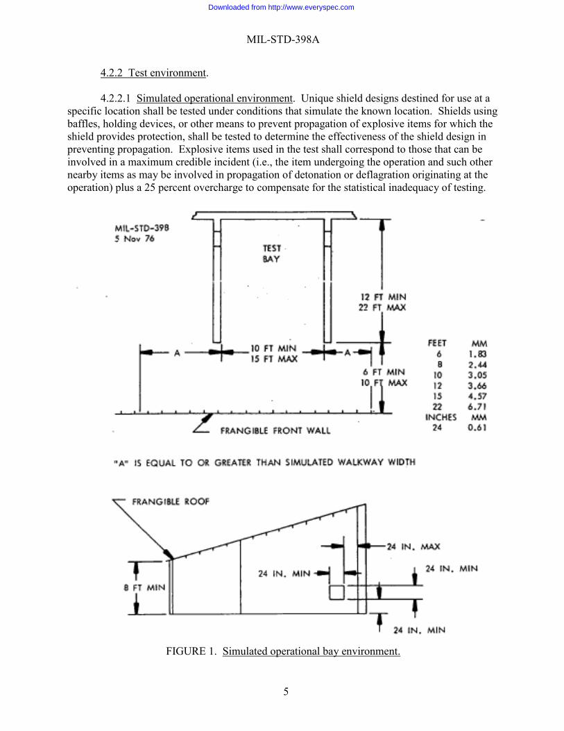
4.2.2.1 Simulated operational environment. Unique shield designs destined for use at a specific location shall be tested under conditions that simulate the known location. Shields using baffles, holding devices, or other means to prevent propagation of explosive items for which the shield provides protection, shall be tested to determine the effectiveness of the shield design in preventing propagation. Explosive items used in the test shall correspond to those that can be involved in a maximum credible incident (i.e., the item undergoing the operation and such other nearby items as may be involved in propagation of detonation or deflagration originating at the operation) plus a 25 percent overcharge to compensate for the statistical inadequacy of testing.
FIGURE 1. Simulated operational bay environment.
Downloaded from http://www.everyspec.com

MIL-STD-398A
6
4.2.2.2 Simulated operational bay environment. Shields designed for use in an operating bay shall be tested in a simulated operational bay environment (Fig. 1) which simulates a bay(s) of a typical ammunition operating building. For test purposes, the test facility shall include the following:
a. Three dividing walls forming a "U" shaped bay at least 10 feet (3.05 meters), and no more than 15 feet (4.57 meters), wide at the opening, and at least 12 feet (3.66 meters), and no more than 22 feet (6.71 meters), from the open end to the back wall. Each side wall should have an opening at least 24 inches (0.61 meters) x 24 inches (0.61 meters), 24 inches (0.61 meters) above the floor within 24 inches (0.61 meters) of the back, to simulate conveyor openings between bays.
b. A hall or aisle across the front opening of "U" shaped bay, at least 6 feet
(1.83 meters), and no more than 10 feet (3.05 meters), wide. c. A "U" shaped bay of similar size shall be attached to the test bay, to simulate
adjacent bays in an operating building. d. A frangible front wall and ceiling (roof) attached to a wood or steel frame.
Other equipment that can be identified as necessary to the operation shall be located in the bay at the time of the test. This equipment can be of a simulated nature, if approved by authorized authority.
4.2.3 Test methods. Shields shall be tested as required to assure conformance with design requirements, using methods detailed in Section 5 of this standard. Tests may be made in any sequence or combination which will result in the most efficient accomplishment of the test objectives.
Downloaded from http://www.everyspec.com
MIL-STD-398A
7
5. DETAILED REQUIREMENTS
5.1 Test methods. Standard procedures for testing and evaluating operational shields to assure compliance with applicable design criteria are specified in the following individual test methods. In order for a shield to be acceptable, the shield shall be tested with the munition(s) for which it was designed under environmental conditions simulating the actual operation and shall have successfully met the criteria in test methods 101 or 102, 201, and 301. 6. NOTES (This section contains information of a general or explanatory nature that may be helpful but is not mandatory)
6.1 Intended use. This standard defines the minimum criteria necessary to design an operational shield which will protect personnel and assets from thermal, pressure and fragmentation hazards resulting from an accidental or intentional detonation of ammunition or explosives; and identifies methods for testing prototype operational shields to assess the degree to which they meet the protection criteria specified. 6.2 Acquisition requirements. Acquisition documents should specify the following:
a. Title, number, and date of the standard. b. The design activity should submit a test plan as specified for review and approval
before conducting any testing. The test plan should specify those test methods contained herein which are applicable to the design criteria. At the conclusion of the test a report documenting test results should also be submitted.
6.3 Documentation.
6.3.1 Test plan. A test plan should be prepared by the testing activity prior to performing
any test and submitted for review and approval as specified in the contract or order. The test plan should include, as a minimum:
a. Statement of Purpose, including pertinent background information. b. Outline of the objectives to be achieved by the test. This section should include a
description of the operational shield to be tested, the criteria governing the design and the operational use of the shield.
c. Procedure to be used to achieve test objectives, layout of equipment, location and
purpose of instrumentation, listing of data to be recorded during the test, and any special considerations.
Downloaded from http://www.everyspec.com

MIL-STD-398A
8
d. Method to be used to interpret test data and observations to evaluate operational shield design.
6.3.2 Test report. A report documenting the design and testing of each shield should be
prepared and submitted as specified in the contract or order. The test report should be used as a basis for evaluating the operational shield design and should include as a minimum:
a. Drawings showing design and construction details of the operational shield. b. An equipment manual giving instructions for set up, operation, and maintenance of the
operational shield, including a description of the shield’s relationship to any allied equipment. c. A complete report of test of prototype shield, including test set up, test procedure, test
results, and analysis of test results. d. Still camera color pictures of operational shield before and after test, including any
pictures needed to illustrate and clarify the set up, discussion, conclusions and recommendations sections of the test report.
e. High speed motion picture camera coverage taken of each test with at least one
camera. Additional cameras or multiple tests with camera(s) at different locations will be used to provide required coverage. Cameras should record event on color film at a speed of at least 400 frames (pictures) per second.
Downloaded from http://www.everyspec.com

MIL-STD-398A
9
METHOD 101
BLAST OVERPRESSURE MEASUREMENT
1 PURPOSE 1.1 Measurement of blast overpressure is conducted to insure that personnel are not
exposed to peak positive incident overpressures greater than 2.3 psi (15.9 kPa), when the operational shield is subjected to a maximum credible incident.
1.2 An acceptable alternative to measuring peak positive incident overpressure is to measure peak positive normal reflected overpressure. Personnel shall not be exposed to maximum positive normal reflected overpressure greater than 5.0 psi (34kN/m2), when the operational shield is subjected to a maximum credible incident.
2. DESCRIPTION OF TEST. A maximum credible incident is created with the operational
shield. Blast pressure gages are used to measure blast overpressures. 3. CRITERIA FOR PASSING TEST. The operational shield shall be considered
acceptable if it can be determined from pressure-distance plot of test data, that personnel will not be exposed to peak positive incident overpressures above 2.3 psi (16kN/m2) or peak positive normal reflected overpressure above 5.0 psi (34kN/m2).
4. INSTRUMENTATION. Blast pressure gages and electronic recording system. Based
on the equivalent test charge weight of explosives and anticipated peak overpressure, the instrumentation system shall have the necessary response time and bandwidth to acquire data. Instrumentation shall be calibrated in accordance with current procedures in TB 43-180, Calibration Requirements for the Maintenance of Army Materiel.
5. TEST PROCEDURE 5.1 Location of blast gages. 5.1.1 When the shield is tested in a simulated operational bay environment, overpressure
readings shall be taken at the following locations:
a. At the center of probable head locations of each operator. For standing locations the gages shall be positioned 65 inches (1.65 meters) above the floor; for sitting locations it shall be 31.5 inches (0.80 meters) above the seat.
b. At representative positions where transient personnel may be located.2
2 Gage locations shall be as designated by the design activity in the test plan and approved by authorized authority.
Downloaded from http://www.everyspec.com

MIL-STD-398A
10
METHOD 101
5.1.2 When testing is conducted in the open air, position blast gages around the shield in two or three concentric circles at distances where it is expected that overpressures of interest will be found. Stagger the gages so shock waves reaching the outer circles are not distorted by gages in the inner circle. The gages shall be placed at a height of 65 inches (1.65 meters).
5.2 Test procedure. 5.2.1 All instrumentation shall be within calibration at time of test. 5.2.2 If the shield is designed for use with more than one model or type of ammunition,
select the item that would produce a maximum overpressure. 5.2.3 Apply an overload equal to 25 percent or more of the filler weight of the ammunition
item selected for the test, unless otherwise directed in an approved test plan. 5.2.4 All major explosive components should be fused separately, to insure simultaneous
detonation or deflagration, in order to simulate the maximum credible incident, unless otherwise directed in an approved test plan.
5.2.5 Function explosives and record overpressure readings. 5.2.6 Prepare pressure-distance plots from overpressure recordings.
Downloaded from http://www.everyspec.com

MIL-STD-398A
11
METHOD 102
IMPULSE NOISE LEVEL MEASUREMENT
1. PURPOSE. Impulse noise level measurement is conducted to insure that personnel are not exposed to a sound pressure level greater than 140 decibels during operations requiring the intentional detonation of ammunition item(s) with an operational shield.
2. DESCRIPTION OF TEST. A maximum credible incident is created with the operational
shield. Sound level meters are used to measure sound pressure levels. 3. CRITERIA FOR PASSING TEST. The operational shield shall be considered
acceptable if it can be determined from noise level readings that personnel will not be exposed to overpressures greater than 140 decibels.
4. INSTRUMENTATION. All instrumentation shall meet requirements of
MIL-STD-1474. 5. TEST PROCEDURE 5.1 Location of microphones. 5.1.1 When the shield is tested in a simulated operational bay environment, noise level
readings shall be taken at the following locations:
a. At the center of probable head locations of each operator. For standing locations the microphones shall be positioned 65 inches (1.65 meters) above the floor; for sitting locations it shall be 31.5 inches (0.80 meters) above the seat.
b. At representative positions where transient personnel may be located.3
5.2 Test procedure. 5.2.1 All instrumentation shall be within calibration at time of test. 5.2.2 If the shield is designed for use with more than one model or type of ammunition,
select the item for maximum noise level. 5.2.3 Apply an overload equal to 25 percent or more of the filler weight of the ammunition
selected for the test, unless otherwise directed in an approved test plan.
3 Microphone locations shall be as designated by the design activity in the test plan and approved by authorized
authority.
Downloaded from http://www.everyspec.com

MIL-STD-398A
12
METHOD 102
5.2.4 All major explosive components should be fused separately, to insure simultaneous detonation or deflagration, in order to simulate the maximum credible incident, unless otherwise directed in an approved test plan.
5.2.5 Function explosives and record noise level readings.
Downloaded from http://www.everyspec.com

MIL-STD-398A
13
METHOD 201
FRAGMENT RETENTION TEST
1. PURPOSE. Fragment testing is conducted to verify that a prototype operational shield will meet the following criteria:
a. Contain all fragmentation or direct fragmentation away from areas requiring
protection. b. Prevent generation of secondary fragmentation within areas requiring protection. c. Prevent movement, overturning, or structural deflections which could result in
personnel injury. 2. DESCRIPTION OF TEST. A maximum credible incident is created to test the
operational shield. 3. CRITERIA FOR PASSING TEST. The operational shield shall do the following:
a. Contain all fragmentation or direct fragmentation away from areas requiring protection.
b. Prevent generation of secondary fragmentation within areas requiring protection. c. Prevent movement, overturning, or structural deflections which could result in
personnel injury. 4. TEST EQUIPMENT. Still picture camera equipment. 5. TEST PROCEDURE 5.1 Fragment retention test. 5.1.1 If the shield is designed for use with more than one model or type of ammunition,
select that item which will have the greatest potential fragmentation or shape charge effect. Equipment, or a reasonable simulation thereof, which perform the intended function on the ammunition, shall be positioned to generate secondary fragments.
5.1.2 Apply an overload equal to 25 percent or more of the filler weight of the ammunition
selected for the test, unless otherwise directed in an approved test plan.
Downloaded from http://www.everyspec.com

MIL-STD-398A
14
METHOD 201
5.1.3 All major explosive components should be fused separately, to insure simultaneous detonation or deflagration, in order to simulate the maximum credible potential incident, unless otherwise directed in an approved test plan.
5.1.4 Function explosives. 5.2 Post-test procedure. 5.2.1 Examine the interior and exterior of the shield for evidence of fragments. Photograph
the shield to document test results. 5.2.2 Examine shield for movement, overturning, or structural deflections which could have
resulted in personnel injury. 5.2.3 Shields designed for intentional detonation shall be examined for damage and an
estimate made as to ability of the shield to remain operational as specified in the design criteria.
Downloaded from http://www.everyspec.com

MIL-STD-398A
15
METHOD 301
HEAT FLUX MEASUREMENT
1. PURPOSE. Heat flux measurement is conducted to insure that personnel are not exposed to a maximum radiant heat flux as determined in the equation given in paragraph 4.1.3 of this standard.
2. DESCRIPTION OF TEST. A maximum credible incident is created. Heat flux
transducers are used to measure radiant heat flux. 3. CRITERIA FOR PASSING TEST. The operational shield shall be considered
acceptable if it can be determined, from heat flux-distance and heat flux-time plots of test data, that personnel will not be exposed to a radiant heat flux rating exceeding the formula in paragraph 4.1.3 of this standard.
4. INSTRUMENTATION. Heat flux transducers and electronic recording system. Based
on the thermal flux expected at the location of the transducers, the instrumentation system shall have the necessary response time and bandwidth to acquire data. Instrumentation shall be calibrated in accordance with current procedures in TB 43-180, California Requirements for the Maintenance of Army Materiel.
5. TEST PROCEDURE 5.1 Location of transducers 5.1.1 When the shield is tested in a simulated operational bay environment, heat flux
readings shall be taken at the following locations:
a. At the center of probable head location of each operator. For standing locations the transducers shall be positioned 65 inches (1.65 meters) above the floor; for sitting location it shall be 31.5 inches (0.80 meters) above the seat.
b. At representative positions where transient personnel may be located.4
5.1.2 In a free field test, flux values at various distances from the point of detonation can be
estimated by the relationship O1d12=O2d2
2, where ∅= Heat flux in cal/cm2-sec. d= Distance from point of detonation.
4 Transducer locations shall be as designated by the design activity in the test plan and approved by authorized
authority.
Downloaded from http://www.everyspec.com

MIL-STD-398A
16
METHOD 301
5.2 Test procedure. 5.2.1 All instrumentation shall be within calibration at time of test. 5.2.2 If the shield is designed for use with more than one model or type of ammunition,
select the item for the greatest heat flux. 5.2.3 Apply an overload equal to 25 percent or more of the filler weight of the ammunition
selected for the test, unless otherwise directed in an approved test plan. 5.2.4 All major explosive components should be fused separately, to insure simultaneous
detonation or deflagration, in order to simulate the maximum credible incident, unless otherwise directed in an approved test plan.
5.2.5 Function explosives and record radiant flux readings. 5.2.6 Prepare heat flux-distance and heat flux-time plots from radiant heat flux recordings.
6. NOTES (This section contains information of a general or explanatory nature that may be helpful, but is not mandatory.) 6.1 Subject term (key word) listing. Blast attenuation Deflagration
Detonation Impulse Pressure
Thermal effect
Downloaded from http://www.everyspec.com

MIL-STD-398A
17
CONCLUDING MATERIAL Custodian: Preparing activity: Army - AR Army - AR Navy - OS (Project 4925-2013-002) Air Force - 99 Review activities: Army – AV, MI Navy – AS, MC, SH Air Force – 70 DLA – GS, GS6 Other: GSA - FAS Agent: DDESB NOTE: The activities listed above were interested in this document as of the date of this document. Since organizations and responsibilities can change, you should verify the currency of the information above using the ASSIST Online database at https://assist.dla.mil/.
Downloaded from http://www.everyspec.com