Embed Size (px)
Citation preview

Department of
Civil Engineering
1
SHIVAJI UNIVERSITY, KOLHAPUR
BE (Civil) Syllabus Structure
SEMESTER-VIII (Part II)
Sr.
No.
Subject Teaching scheme per week Examination scheme
L P T D Total Theory
paper
TW POE OE Total
1 Design of Concrete
Structures-II
4 2 --- --- 6 100 25 --- --- 125
2 Water Resource Engineering -
II
3 2 --- --- 5 100 25 --- 25 150
3 Transportation Engineering-II 3 --- --- --- 3 100 --- --- --- 100
4 Elective-II* 3 --- --- --- 3 100 --- --- --- 100
4 Elective –III** 3 --- --- --- 3 100 --- --- --- 100
6 SDD-II --- --- --- 4 4 --- 50 --- 25 75
7 PROJECT --- 6 --- --- 6 --- 75 75 --- 150
Total 16 10 --- 4 30 500 175 75 50 800
*Elective from structure group, **Elective from non-structure group

Department of
Civil Engineering
2
Department of Civil Engineering
T. E. Civil
BE-Civil-Part-II
Sr
No
Subject
code
Subject Page No.
1 CE 417 Design of Concrete Structure II 02
2 CE 418 Water Resources Engineering II 16
3 CE419 Transportation Engineering II 29
4 Elective II
4.a CE420 Advanced Concrete Design 38
4.b CE423 Structural Design of Foundation and Retaining Structures 48
5 Elective III
5.a CE434 Advanced Construction Techniques 58
5.b CE431 Site Investigation Methods and Practices 68
6 CE435 Structural Design and Drawing II 76
7 CE436 Project work Phase II 79

Department of
Civil Engineering
3
Course plan for Design of Concrete Structures-II
Course Code CE 417 Course Design of Concrete Structures
II
Prepared by Mr. S. R. Kadam / Mr S. P. Patil Semester AY 2017-18, Sem II
Pre-requisites This course requires the student to know about the basic concepts in structural
mechanics like shear force , bending moment, stress, strain, Basic properties of
concrete and reinforcing bars and concept of Reinforced cement concrete.
Course Outcomes
At the end of the course the students should be able to:
CO417.1 Analyze4 and design the beams subjected to combined action of bending and
torsion.
CO417.2 Analyze4 and design continues beam and slab.
CO417.3 Design5 circular and rectangular water tanks resting on ground
CO417.4 Explain2 the basic concept of prestressed concrete
CO417.5 Calculate4 the losses of prestress due to elasticity, creep, shrinkage etc
CO417.6 Analyze4 and design of prestressed concrete rectangular and T beams.
Mapping of COs with POs
POs
COs
a b c d e f g h i j K
CO417.1 1 1
CO417.2 1 2 2
CO417.3 2 2 1
CO417.4 1 2 1
CO417.5 3 2
CO417.6 1
1 Mild correlation 2 Moderato correlation 3 Strong
correlation

Department of
Civil Engineering
4
Course Contents
Unit
No. Title
No. of
Hours
Section I
1. Limit State of Collapse:
Torsion Behavior of R.C. rectangular sections subjected to torsion, Design of
sections subjected to combined bending and torsion, combined shear and
torsion.
07
2. Limit state Design of two span continuous beams and three span continuous
beams using IS coefficient, concept of moment redistribution 08
3. Design of water tank :
Introduction to working stress method for water tank design, Design criteria,
permissible stresses, design of water tank resting on ground using IS code
method – (i) circular water tanks with flexible and rigid joint between wall and
floor, (ii) rectangular water tanks.
09
Section II
4. Basic concept of prestressing. Historical development. Types and systems of
prestressing. Analysis of rectangular and symmetrical I sections. Different
cable profiles.
08
5. Losses of prestress in Pre & Post tensioned members. Flexural strength of
prestress concrete section 06
6. Design of prestress concrete:
Rectangular and Symmetrical I sections for following criteria: (i) Design of
section for flexure (ii) Design of section for the limit state of collapse in
flexure.
10
Reference books:
Sr.
No.
Title of Book Author Publisher/Edition Topics
covered
1. IS: 456-2000 ,IS: 3370, IS:
1343
IS INDIAN
STANDARD

Department of
Civil Engineering
5
2. Reinforced Cement Concrete -B.C. Punmia 1,2,3
3. Limit State Theory & design - Karve& Shah Structures Pub.
pune
1,2,3
4. Reinforced Concrete Design
(Limit State) -
A.K. Jain 2,3
5. Fundamentals of Reinforced
Concrete- -
Sinha & Roy 1,2,3,4
6. Reinforced Concrete P.C. Varghese, Prentice Hall of
India,
4,5,6
7. Prestressed Concrete Tata N Krishna Raju, McGraw-Hill
Publication
Company ltd.
4,5,6
8. Prestressed Concrete - Sinha & Roy S.Chand & Co.
NewDelhi
4,5,6
Evaluation scheme:
Examination
Scheme
Theory Term Work OE Total
Max. Marks 100 25 125
Contact
Hours/ week
4 2 -- 5
Scheme of Marks
Section Unit No. Title Marks
I
1 Unit 1 Limit State of Collapse – Torsion 16
2 Unit 2 Limit state Design of two span continuous beams 18
3 Unit 3 Design of water tank 16
II
4 Unit 4 Basic concept of prestressing 16
5 Unit 5 Losses of prestress 18
6 Unit 6 Design of prestress concrete 16

Department of
Civil Engineering
6
Course Unitization
CO Evaluation Remark
CO417.1 CAT 1 1 question on unit 1 and 2 with 15 marks each
CO417.2
CO417.3 CAT 2 1 question on unit 3 and 4 with 15 marks each
CO417.4
CO417.5 CAT 3 1 question on unit 5 and 6 with 15 marks each
CO417.6
Unit wise Lesson Plan
Section I
Unit No Unit Title Planned Hrs.
1 Design for Torsion 07
Lesson schedule
Class
No.
Details to be covered
1 Limit State of Collapse –Torsion Behavior of R.C. rectangular sections subjected to
torsion.
2 Analysis of sections subjected to combined bending and torsion, combined shear and
torsion
3 Design of sections subjected to combined bending and torsion, combined shear and
torsion
4 Design problem.
5 Design problem by following IS code Method.
6 Design problem.
7 Design problem
Review Questions

Department of
Civil Engineering
7
Q1 When we need to consider Torsion in design of beams?
CO417.1
Q2 What is side face reinforcement? Where we have to provide it?
Q3 As per IS code, how to design a beam for combined action of torsion, Bending
and shear?
Q4 Design a RCC beam 300mm wide and 600mm overall depth for factored
bending Moment of 70 kN-m , Factored Torsional moment 45 kN-m and
Factored shear force of 75 kN. Use M20 Concrete and Fe 415 steel.
Q5 Design a RCC beam 300mm wide and 450mm overall depth for factored
bending Moment of 60 kN-m , Factored Torsional moment 40 kN-m and
Factored shear force of 80 kN. Use M25 Concrete and Fe 415 steel.
Unit No Unit title Planned Hrs.
2 Design of Continues Beam 08
Lesson schedule
Class
No.
Details to be covered
1 Review of analysis of continues beams by various methods and discussion on coefficient
method.
2 Limit state design of two span and three span continues beams.
3 Design problem on continues beam.
4 Concept of Redistribution of moments
5 Design of continues beam by incorporating redistribution of moments.
6 Design problems on continues beam
7 Design problems on continues beam
8 Design problems on continues beam
Review Questions
Q1 Describe in brief the coefficient method for analysis of continues beam with its
limitations.
Q2 Write about the concept Redistribution of Moment and its practical importance.
Q3 A two span beam ABC is freely supported at A&C. The beam carries a 230mm
thick 3m high brick wall and superimposed load of 9.0 kN/m. Design critical

Department of
Civil Engineering
8
section of beam AB & BC Using IS code Coeff. Method. Span AB=BC=6m,
Grade of concrete M20, and Steel Fe415.
CO417.2 Q4 A Three span beam ABCD is freely supported at A&D. The beam carries a
230mm thick 3m high brick wall and superimposed load of 10.0 KN/m. Design
critical section of beam AB, BC&CD Using IS code Coeff. Method. Span
AB=BC=CD=5m, Grade of concrete M20, and Steel Fe415 .
Q5 A Three span beam ABCD is freely supported at A&D. The beam carries a
150mm thick 2.5m high brick wall and superimposed load of 15.0 KN/m.
Design critical section of beam AB, BC&CD Using IS code Coeff. Method.
Span AB=BC=CD=4m, Grade of concrete M20, and Steel Fe500
Unit No Unit Title Planned Hrs.
3 Working stress method and Design of Water tanks 09
Lesson schedule
Class
No.
Details to be covered
1 Working stress method of RCC design comparison with LSM.
2 Analysis of singly reinforced section and computation of Design constants.
3 Analysis of Doubly reinforced section and computation of Design constants.
4 Design of One way and Two way slab by WSM.
5 Design constants and permissible stresses.
6 Design of Circular tank resting on ground having flexible base connection.
7 Design of Circular tank resting on ground having rigid base by IS code Method.
8 Design of Circular tank resting on ground having rigid base by approximate method.
9 Design of rectangular tank resting on ground by exact method.
Review Questions
Q1 What is the basic principle behind the WSM ? Compare WSM with LSM.
Q2 What are the assumption in WSM?
Q3 Define the terms with reference to RC beam section- Neutral axis, Under

Department of
Civil Engineering
9
reinforced section, Over reinforced section, Moment of resistance.
CO417.3
CO417.3
Q4 Derive Expression for position of Neutral axis and Moment of Resistance of
a balanced rectangular section.
Q5 Derive Expression for position of Neutral axis and Moment of Resistance of
Doubly reinforced rectangular section.
Q6 A beam of reinforced concrete is 300mm wide and 400mm deep to centre of
tension steel. It is reinforced with four 16mm dia bars in compression and
four bars of 20mm in tension zone with effective cover 50mm. Determine
Moment of resistance of the beam section if permissible stresses in concrete
and steel are not to exceed 7 and 140 N/sqmm. Take m=13.
Q7 Design a rectangular section for a simply supported RC beam of effective
span of 6m carrying an UDL of 20KN/m over entire span. The concrete to be
used is of grade M20 and the reinforcement consist of HYSD steel bar with
grade Fe 415.
Q8 Design a slab for room admeasuring 3mx9m.the slab rests on masonry of
thickness 230mm. Use M20 Concrete and Fe 415 steel
Q9 Write Permissible stresses in concrete and steel as per IS.
Q10 Write in brief the procedure for design of circular water tank resting on
ground with flexible and rigid base.
Q11 Write the procedure of design of rectangular water tank resting on ground by
exact method.
Q12 The section of a RCC wall of a rectangular tank is subjected to direct tension
of 95KN/m and moment of i) 75.0 kNm/m and ii) 5.5 KN m/m. Design the
section when M25 Grade concrete mix and HYSD steel bar of grade Fe415
are to be used under class B exposure condition.
Q13 Design a Cylindrical water tank of capacity 100cum resting on ground
having a flexible base. The material used in construction is M25 grade
concrete mix and HYSD, Fe 415 steel. The overall height of the tank is
restricted to 3.00 m with free board of 200mm. The bearing capacity of soil at
the site is 150 kN/m2.
Q14 Design a rectangular tank resting on ground with internal dimensions
7.0x5.5x2.75(CO3)m high. Take the free board as 300mm. Use M25 grade
concrete and HYSD steel of grade Fe415.
Q15 Design a circular tank with fixed base for capacity of 5000KL resting on
ground having a soil with SBC of 80 KN/sqm. Provide a depth of 5m with Fb
of 250mm. The construction materials to be used are M25 grade concrete and
Fe 500 steel.

Department of
Civil Engineering
10
SECTION II
Unit No. Unit Title Planned Hrs.
4 Introduction to prestressed concrete 08
Lesson schedule
Class
No.
Details to be covered
1 Introduction to Prestressed concrete Types of prestressing.
2 Methods of prestressing and materials specifications.
3 Questions on prestressing
4 Questions on prestressing
5 Systems of prestressing.
6 Concepts in Prestressing.
7 Questions on prestressing
8 Questions on prestressing
Review Questions
Q1 What is the basic principle of prestressed concrete?
CO417.4
Q2 What is necessity of using high strength concrete and high tensile steel in
prestressed concrete?
Q3 Differentiate between Concentric and eccentric prestressing,.
Q4 Differentiate between Pre-tensioning and post-tensioning.
Q5 List various types of tensioning devices used in prestressed concrete.
Q6 Explain various post-tensioning system based on wedge action with sketches.
Unit No Unit Title Planned Hrs.
5 Losses in prestress 06
Lesson schedule
Class Details to be covered

Department of
Civil Engineering
11
No.
1 Nature of losses of prestress
2 Loss of prestress due to elastic deformation of concrete and shrinkage of concrete
3 loss due to creep of concrete and relaxation of steel
4 loss due to friction and anchorage sleep
5 Total losses in pre-tensioned and post-tensioned case.
6 Questions On Prestressing
Review Questions
Q1 List the various types of loss of prestress in pre-tensioned and post-tensioned
members.
CO417.5
Q2 How to calculate the losses of prestress due to above all causes.
Q3 A post tensioned beam of rectangular cross section, 150mm wide and 300mm
deep, is prestressed by eight 7mm wires located 100mm from soffit of the
beam. If the wires are initially tensioned to a stress of 1100 N/sqmm. Calculate
their stress at transfer and the effective stress after all losses. Given the
following data.
Up to time of
transfer
Total
Relaxation of steel 35 N/mm2
70 N/mm2
Shrinkage of concrete 100 x 10-6
300x10-6
Creep coefficient --- 1.60
Es= 210 KN/ mm2
Ec=31.5 KN/ mm2
Q4 A prestressed concrete beam, 200 mm wide and 300 mm deep, is prestressed
with wiers (area = 320 mm2) located at a constant eccentricity of 500 mm and
carrying an initial stress of 1000 N/mm2. The span of the beam is 10 m.
Calculate the percentage loss of stress in wires if (a) the beam is pre-tensioned,
and (b) the beam is post-tensioned, using the following data:
Es = 210kN/mm2andEc = 35kN/mm
2
Relaxation of steel stress = 5 percent of initial stress.
Slip at anchorage = 1 mm
Shrinkage of concrete = 300 x106 for prestensioning and 200 x10
6 for
posttensioning.
Assume any other missing data.

Department of
Civil Engineering
12
Unit No. Unit Title Planned Hrs.
6 Introduction to prestressed concrete 08
Lesson schedule
Class
No.
Details to be covered
1 Basic assumptions, Analysis of prestress for concentric and eccentric tendon.
2 Resultant stresses at a section, examples
3 Resultant stresses at section for Rectangular and I beams
4 Pressure line or thrust line and internal resisting couple
5 Problems on calculation of resultant stresses and location of trust line
6 Load Balancing concept withy examples
7 Design criteria by IS 1343
8 Designing the rectangular section
9 Problems on designing of rectangular beam section
10 Design of pre-tensioned and Post- tensioned beam, dimensioning of section
Review Questions
Q1 Distinguish between concentric and eccentric tendons indicating their practical
applications.
CO417.6
Q2 What is ‘pressure line’? explain significance with sketch.
Q3 Explain concept of internal resisting couple in prestressed concrete beam
supporting dead and live load.
Q4 Explain the difference between load carrying mechanism of reinforced and
prestressed concrete beam with sketch.
Q5 Explain the load balancing concept.
Q6 A Prestressed concrete beam 200x300mm deep is used over an effective span
6m to support an imposed load of kN/m the density of concrete is 24 kN/cum.
At the quarter span section of beam find the magnitude of
i) The concentric prestressing force necessary for zero fibre stress
at the soffit when the beam is fully loaded
ii) The eccentric pretressing force located 100mm from the bottom
of the beam which would nullify the bottom fibre stress due to
Department of
Civil Engineering
13
loading.
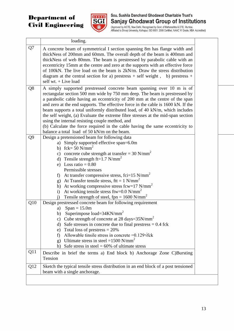
Q7 A concrete beam of symmetrical I section spanning 8m has flange width and
thickNess of 200mm and 60mm. The overall depth of the beam is 400mm and
thickNess of web 80mm. The beam is prestressed by parabolic cable with an
eccentricity 15mm at the centre and zero at the supports with an effective force
of 100kN. The live load on the beam is 2kN/m. Draw the stress distribution
diagram at the central section for a) prestress + self weight , b) prestress +
self wt. + Live load
Q8 A simply supported prestressed concrete beam spanning over 10 m is of
rectangular section 500 mm wide by 750 mm deep. The beam is prestressed by
a parabolic cable having an eccentricity of 200 mm at the centre of the span
and zero at the end supports. The effective force in the cable is 1600 kN. If the
beam supports a total uniformly distributed load, of 40 kN/m, which includes
the self weight, (a) Evaluate the extreme fibre stresses at the mid-span section
using the internal resisting couple method, and
(b) Calculate the force required in the cable having the same eccentricity to
balance a total load of 50 kN/m on the beam.
Q9 Design a pretensioned beam for following data
a) Simply supported effective span=6.0m
b) fck= 50 N/mm2
c) concrete cube strength at transfer = 30 N/mm2
d) Tensile strength ft=1.7 N/mm2
e) Loss ratio = 0.80
Permissible stresses
f) At transfer compressive stress, fci=15 N/mm2
g) At Transfer tensile stress, ftt = 1 N/mm2
h) At working compressive stress fcw=17 N/mm2
i) At working tensile stress ftw=0.0 N/mm2
j) Tensile strength of steel, fpn = 1600 N/mm2
Q10 Design prestressed concrete beam for following requirement
a) Span = 15.0m
b) Superimpose load=34KN/mm2
c) Cube strength of concrete at 28 days=35N/mm2
d) Safe stresses in concrete due to final prestress = 0.4 fck
e) Total loss of prestress = 20%
f) Allowable tinsile stress in concrete =0.129√fck
g) Ultimate stress in steel =1500 N/mm2
h) Safe stress in steel = 60% of ultimate stress
Q11 Describe in brief the terms a) End block b) Anchorage Zone C)Bursting
Tension
Q12 Sketch the typical tensile stress distribution in an end block of a post tensioned
beam with a single anchorage.

Department of
Civil Engineering
14
Model Question Paper
Course Title : Design of Concrete Structure II
Duration-3 Hrs. Max. Marks: 100
Instructions:
1 Answer any three equations from section I and three from section II
2 Missing data may be assumed with proper justification.
3 Use of IS 456 & IS1343 permitted during exam.
Section-I
Section-II
5 a) Explain in details the three concepts in analysis of prestresses concrete. 06
1 a) When and how we include Torsion in design of beams? 06
b) Design a RCC beam 300mm wide and 600mm overall depth for factored
bending Moment of 70 kN-m , Factored Torsional moment 40 KN-m and
Factored shear force of 56 kN. Use M20 Concrete and Fe 415 steel
10
2 A Three span beam ABCD is freely supported at A&D. The beam carries an
superimposed load of 25 kN/m excluding its self weight. Design critical
section of beam AB,BC,CD Using IS code Coeff. Method. Span
AB=BC=CD=6m, Grade of concrete M20, and Steel Fe415.
17
3 a) Derive Expression for position of Neutral axis and Moment of Resistance of
a doubly reinforced beam section.
05
b) A rectangular section of a simply supported RC beam of effective span of 6m
having overall dimensions 230x450 consists of 2 bars of 16mm at top and 4
bars of 16mm at bottom. Determine the safe load it can carry if the concrete
used is of grade M20 and the reinforcement consists of HYSD steel bar with
grade Fe 415. (CO2)
12
4 Design a circular water tank of capacity 50KL resting on ground having a
rigid base to wall connection. The material used in construction is M25 grade
concrete mix and HYSD, Fe 415 steel. The overall height of the tank is
restricted to 2.50 m. The bearing capacity of soil at the site is 200
KN/m2(CO3)
17

Department of
Civil Engineering
15
b) Differentiate between a) pre-tensioning and post-tensioning, b) Internal and
external prestressing.
12
6 a) A concrete beam of symmetrical I section spanning 8m has flange width and
thickNess of 200mm and 60mm. The overall depth of the beam is 400mm and
thickNess of web 80mm. The beam is prestressed by parabolic cable with an
eccentricity 15mm at the centre and zero at the supports with an effective force
of 100KN. The live load on the beam is 2KN/m. Draw the stress distribution
diagram at the central section for a) prestress + self weight , b) prestress + self
wt. + Live load.
04
7 a) What are the causes of losses in prestressing?. 05
b) A prestressed concrete beam, 200 mm wide and 300 mm deep, is prestressed
with wiers (area = 320 mm2) located at a constant eccentricity of 500 mm and
carrying an initial stress of 1000 N/mm2. The span of the beam is 10 m.
Calculate the percentage loss of stress in wires if (a) the beam is pre-tensioned,
and (b) the beam is post-tensioned, using the following data:
Es = 210kN/mm2andEc = 35kN/mm
2
Relaxation of steel stress = 5 percent of initial stress.
Slip at anchorage = 1 mm
Shrinkage of concrete=300 x106 for pre-tensioning and 200 x10
6 for post-
tensioning.
Assume any other missing data.
12
8 Design prestressed concrete beam for following requirement
a) Span = 12.0m
b) Superimpose load=30kN/mm2
c) Cube strength of concrete at 28 days=35N/mm2
d) Safe stresses in concrete due to final prestress = 0.4 fck
e) Total loss of prestress = 20%
f) Allowable tinsile stress in concrete =0.129√fck
g) Ultimate stress in steel =1600 N/mm2
h) Safe stress in steel = 60% of ultimate stress
17
Practical/ Assignments:
List of experiments/assignments to meet the requirements of the syllabus
Assignment no. Assignment Title
1 Limit State of Collapse (Torsion)
2 Limit state Design of two span continuous beams
3 Design of water tank
4 Analysis of prestress concrete

Department of
Civil Engineering
16
5 Losses of prestress
6 Design of prestress concrete
All Batches Minimum one assignment on each unit

Department of
Civil Engineering
17
Course plan for Water Resources Engineering. II
Course Code CE 418 Course Structural Mechanics II
Prepared by Mr. S. R. KADAM / Mr
N.U.Bavane
Semester AY 2017-18, Sem II
Pre-requisites This course requires the student to know about the basic concepts regarding
various dams, their site selection, design of various dams, spillways, river
training works and hydroelectric power generation.
Course Outcomes
At the end of the course the students should be able to:
CO418.1 Explain2 the basics regarding site selection criteria for reservoir as well as dams.
Design earth dam by slip circle method, to study various failures and seepage
control of earth
CO418.2 Demonstrate3 the various forces acting on gravity dam with magnitude and
direction, stability calculations regarding gravity dam.
CO418.3 Discuss2 various types of spillways and spillway gates, methods of dissipation of
energy.
CO418.4 Discuss2 diversion headwork and Bligh’s & Khosla’s seepage theories
CO418.5 Explain4 typical canal sections, Kennedy & Lacey’s silt theories, and various
cross drainage works.
CO418.6 Discuss2
meandering phenomenon, types of river training work and its design,
Hydro power generation process and layout of it with its components
Mapping of COs with POs
POs
COs
a b c d e f g h i j K
CO418.1 3 2
CO418.2 3 3 2 2
CO418.3 3 2 2
CO418.4 3 2
CO418.5 3 2
CO418.6 3 1

Department of
Civil Engineering
18
1 Mild correlation 2 Moderato correlation 3 Strong
correlation
Course Contents
Unit
No. Title
No. of
Hours
Section I
1. Planning of Reservoirs: Storage Calculations, Control levels, silting of
reservoirs, Losses in reservoirs
Dams: Introduction, necessity, types of dams, selection of site for dams,
selection of type of dam. Introduction to Instrumentation in dams
Earth dam:
Components and their functions check list for design control of seepage
through earth dam and foundation stability of slopes, slip circle methods,
filters in earth dam and their design, drainage of earth dam, construction of
earth dam.
08
2. Gravity Dams:
Forces acting on dam, design criteria, theoretical and practical profile, high
and low dam, stability calculations, methods of construction, galleries and
joints in dams. Arch dams – types, layouts of constant angle and constant
radius arch dams
07
3. Spillway:
Necessity and function components of spillway, different types, factors
affecting choice of type of spillway. Elementary hydraulic design, types of
energy dissipation arrangements, gates for spillway. Outlets in Dams: Outlets
through concrete and earth dams, different types, determination of important
control levels, choice of type of energy dissipation in outlets transition.
05
Section II
4. Diversion Head Works:
Introduction, types, component parts, Causes of failure and remedies
Introduction to Theory of seepage - Bligh's creep theory, exit gradient,
Khosla's theory,
05
5. Canals: Types, alignment, Kennedy’s and Lacey’s silt theories, typical
sections of canals, balancing depth, canal lining - purpose, types, selection and
economics.
C.D. Works: Necessity, aqueduct, culvert, super passage, level crossing,
Canal Regulatory Works: head regulator, cross regulator, canal siphon, canal
fall, canal escape, standing wave flume
05
6. River Engineering: Classification and types of rivers, meandering
phenomenon, River training works, Classification, Types, Design 04
Department of
Civil Engineering
19
considerations for Guide banks and Groynes, River navigation. Interlinking of
rivers, National perspective plan, Himalayan and peninsular river component
Elements of hydro-power: Water power, importance, types of water power
plan layout and components of each type. Intakes, conveyance system, surge
tanks, Power house types, Components and layout, Tail race.
Reference books:
Sr.
No.
Title of Book Author Publisher/Edition Topics
covered
1. Irrigation Engg. S. K. Garg.
P.N.Modi
Khanna
publications
ALL
2. Irrigation and water resource
engineering
B.C. Punmia, Jain Khanna
publications
ALL
3. Irrigation and water resource
engineering
K. R. Arora Standard
publications
ALL
Evaluation scheme:
Examination
Scheme
Theory Term Work OE Total
Max. Marks 100 25 25 150
Contact
Hours/ week
3 2 -- 5
Scheme of Marks
Section Unit No. Title Marks
I
1 Unit 1 Introduction to dams, Earthen dams 18
2 Unit 2 Gravity dams 16
3 Unit 3 Spillway, Outlets in Dams 16
II 4 Unit 4 Diversion head works 18
Department of
Civil Engineering
20
5 Unit 5 Canals, CD works, Canal Regulatory Works 16
6 Unit 6 River engineering, River training works, Elements of
hydropower
16
Course Unitization
CO Evaluation Remark
CO418.1 CAT 1 1 question on unit 1 and 2 with 15 marks each
CO418.2
CO418.3 CAT 2 1 question on unit 3 and 4 with 15 marks each
CO418.4
CO418.5 CAT 3 1 question on unit 5 and 6 with 15 marks each
CO418.6
Unit wise Lesson Plan
Section I
Unit No Unit Title Planned Hrs.
1 Planning of reservoir 08
Lesson schedule
Class
No.
Details to be covered
1 Storage reservoir & its types, Storage zones. Reservoir Sedimentation & It’s control
measures.
2 Area Elevation curve, Elevation Capacity curve & reservoir losses.
3 Site selection criteria for a dam & a new reservoir
4 Site selection criteria for type of dam & Instrumentation of dam
5 Earth dam, types of earthen dam, Slip circle method.

Department of
Civil Engineering
21
6 Failures in Earthen dam.
7 Seepage control in earthen dam or drainage systems in earthen dam.
8 Construction of earthen dam.
Review Questions
Q1 Explain control levels or storage zones of reservoir with neat sketch.
CO418.1
Q2 What are the different types of reservoir? Explain each.
Q3 What is Reservoir Sedimentation?
Q4 Describe various methods of controlling sedimentation of reservoir.
Q5 Explain how the area elevation curve & elevation capacity curve are prepared.
Q6 Explain the points which will consider while selecting site for new reservoir.
Q7 What are the different losses of reservoir?
Q8 What are the different factors affecting for selection of type of dam?
Q9 Explain briefly how will you determine long term storage requirement using mass
curve. Assume rate of demand is constant
Q10 Explain mass inflow curve & mass demand curve
Q11 What is instrumentation of dam? Why it is required?
Q12 Describe in brief various investigations required for reservoir planning.
Unit No Unit title Planned Hrs.
2 GRAVITY DAM 07
Lesson schedule
Class
No.
Details to be covered
1 Gravity dam, forces acting on gravity dam with their magnitude and direction.

Department of
Civil Engineering
22
2 High & low gravity dam, its design criteria, theoretical profile & practical profile of
gravity
Dam.
3 Modes of failure of gravity dam , stability analysis
4 Construction of gravity dam & methods adopted for control of temp. in construction.
5 Galleries and joints in gravity dam
6 Arch dam – introduction & types
7 Dams instrumentation
Review Questions
Q1 What are the various forces acting on gravity dam? Explain each with their 23
magnitude and direction
CO418.2
Q2 High & low gravity dam, its design criteria, theoretical profile & practical
profile of gravity dam.
Q3 Discuss the modes of failure of solid gravity dam.
Q4 State & explain theoretical profile & practical profile of gravity dam.
Q5 Write an explanatory note on galleries in gravity dam and give function of
them.
Q6 Discuss methods adopted for control of temperature in gravity concrete dam.
Q7 What are different joints required for gravity dam?
Q8 Discuss thin cylinder theory for design of Arch dam & give its limitations.
Q9 Define Arch dam. Sketch the layouts of types of Arch dam.
Q10 Write note on instrumentation of Gravity dam.
Q11 Determine forces due to self weight, water pressure& uplift pressure on the non
overflowing dam for following given data:
Specific weight of concrete = 24 kN/m3
Total depth of water = 53 m
On u/s face, bottom 20m has slope of 1V to 1H
Freeboard =3m,Top Width = 7m
d/s slope 1V to 0.75H starts at 14 m from top of the dam. Draw the section.
Q12 Following data were obtained from the stability analysis of a concrete gravity
dam.
Total resisting moment about toe =14.715 x 10⁵ kN/m
Total overturning moment about toe =9.81 x 10⁵ kN/m
Total vertical force about base =49.05 x 10³ kN

Department of
Civil Engineering
23
Base width of the dam =50 m
Slope of d/s face of dam = 0.7:1
Calculate the maximum and minimum vertical stress to which the foundation
will
be subjected to. Also calculate maximum principal stress &shear stress
developed
at toe. Assume there is no tail water. .
Unit No Unit Title Planned Hrs.
3 Spillway 5
Lesson schedule
Class
No.
Details to be covered
1 Components of spillway, types of spillways.
2 types of spillways
3 Spillway gates.
4 Energy dissipater, Stilling basin, its components.
5 Types of stilling basin, Outlet through concrete and earthen dam, trash rack
Review Questions
Q1 State & explain spillway & its components.
CO418.3
Q2 What are the different types of spillways? Explain each with neat sketches.
Q3 Write note on trash rack.
Q4 What is stilling basin? Explain its components with their functions.
Q5 What are different types of spillway gates? Explain each in detail.
Q6 Discuss the various design consideration of ogee spillway.
Q7 What is energy dissipation? What are the various energy dissipater used ?
Q8 Sketch the typical layout of outlet through earthen dam & gravity dam.
SECTION II

Department of
Civil Engineering
24
Unit No. Unit Title Planned Hrs.
4 Diversion headwork 5
Lesson schedule
Class
No.
Details to be covered
1 Diversion headwork , components of diversion of headwork.
2 Bligh’s theory for weir design on permeable foundation.
3 Khosla’s seepage theory.
4 Silt excluder, silt extractor, Exit gradient, critical exit gradient
5 Diversion headwork , components of diversion of headwork.
Review Questions
Q1 What is the exit gradient & critical exit gradient
CO418.4
Q2 Write Bligh’s theory of seepage flow with safety against piping & safety
against
uplift pressure
Q3 Write note on :-1) Silt excluder
2) Silt extractor.
3)Fish ladder
4) Divide wall
Q4 Write the khosla’s for weir design on permeable foundation
Q5 What are the main causes of failure of weirs on permeable foundation?
Discuss.
Unit No Unit Title Planned Hrs.
5 Canal and cross drainage work 5
Lesson schedule
Class
No.
Details to be covered
1 Canal alignment, typical c/s of canal, canal lining. Kennedy’s & Lacey’s silt theories.

Department of
Civil Engineering
25
2 Types of canal lining & purpose of lining
3 C.D. Works, its necessity, aqueduct, siphon aqueduct.
4 Super passage, level crossing, Head regulator & cross regulator.
5 Canal siphon, canal escape, canal fall.
Review Questions
Q1 Describe different types of lining done on channels. What are the factors that
in
fluences the choice of particular type of lining?
CO418.5
Q2 Enlist different types of canal & explain each.
Q3 Draw a typical canal c/s which is partly in cutting and partly in filling &
discuss
briefly its components.
Q4 What is mean by regime channel? Compare briefly kennedy & lacey’s silt
theories.
Q5 Discuss the silt theory by Kennedy for regime channel.
Q6 Discuss the silt theory by Lacey’s for regime channel.
Q7 Explain briefly the necessity of lining & also justify economic of canal lining.
Q8 Discuss various types of C.D. works used in canal system. What
considerations
govern the selection of different types of C.D. works? Illustrate by drawing
neat
sketch of each structure.
Q9 Write note on canal fall
Unit No Unit Title Planned Hrs.
6 River engineering and hydro power elements 4
Lesson schedule
Class
No.
Details to be covered
1 Classification & meandering phenomenon of river, Types of river training works,
Interlinking
Department of
Civil Engineering
26
of river.
2 Methods of river training works, Design consideration of groynes & guide banks
3 Importance of hydro power, types of hydro power plant, Layout & component of Hydro
power
plant with their functions.
4 Intake, conveyance system & surge tank, types of surge tank, Powerhouse, tail race.
Review Questions
Q1 Write note on types of river & their characteristics.
CO418.6
Q2 What are the classifications of river training work?
Q3 What are the methods of river training work? Explain each with neat sketches.
Q4 What are the purposes of river training?
Q5 What is meandering of river? Explain its causes & effects.
Q6 Write design criteria for guide bank?
Q7 Write note on Interlinking of river.
Q8 Write various meander parameters.
Q9 Discuss the importance of Hydro power in scenario of Indian power
requirement.
Model Question Paper
Course Title : WATER RESOURCE ENGG. II
Duration-3 Hrs. Max. Marks: 100
Instructions:
1 Attempt any three questions from each section
2 Figures to the right indicate full marks.
3 Wherever required neat sketches shall be drawn.
Section-I

Department of
Civil Engineering
27
Section-II
4 a) What is barrage? How it differs from a weir? Describe with neat sketches
types of weirs.
08
b) Determine maximum &vertical stresses to which foundation of dam will
subjected to following data.
Total overturning moment @toe = 1.2 x 10⁶ KN-m
Total resisting moment @toe = 2.5 x 10⁶ KN-m
Total vertical forces @ base = 6 x 10⁴ KN
Base width = 55 m
Slope @ d/s face = 0.8 : 1
Also calculate the principal stresses @ toe , neglect tail water.
08
5 a) What is mean by regime channel? Compare briefly kennedy & lacey’s silt
theories.
08
b) Classify different types of canals. Describe briefly the various considerations 08
1 a) Discuss with sketch, the different storage zones of reservoir. 04
b) What is stilling basin? Explain its components with their functions 04
c) What is Phreatic line or seepage line? Give its characteristics. 04
d) Write note on instrumentation of Gravity dam. 04
2 a) Define mass inflow curve & mass demand curve. Explain briefly how will
you determine long term storage requirement using mass curve. Assume rate
of demand is constant.
06
b) What are the various forces acting on gravity dam? Explain any three with
their magnitude and direction.
06
c) Give the classification of earthen dam & explain one with neat sketch. 04
3 a) Explain theoretical & practical profile. Design & draw the practical profile
having height of dam = 70 m & specific gravity of material = 2.4
08
b) Write notes on (any two)
1)Multipurpose reservoir projects
2) Galleries in gravity dams
3)Rockfill dam
4)Ogee spillway
10

Department of
Civil Engineering
28
made in the alignment of a canal. Comment on economics of canal lining.
6 a) Describe the functions of guide bank. Further explain design criteria for guide
bank
for length of waterway, length of guide bank, radius of curved heads & cross
section.
08
b) Write note on (any two) :-1) canal fall
2) canal escape
3)canal regulatory work
08
Practical/ Assignments:
List of experiments/assignments to meet the requirements of the syllabus
Assignment no. Assignment Title
1 Determination of height of dam: Determine demand/supply reservoir
calculation and control levels and free board.
2 Earthen dam: Determination of section (drawing of one plate), one slip
circle calculations, types of failure.
3 Gravity dam: Forces acting, modes of failure
4 Design of gravity dam: Elementary and practical profile with stability
calculations and layout of arch dam
5 Design of spillway, geometrical section & energy dissipation arrangement
and gates, outlet through earth and gravity dams
6 Typical section of diversion head works, Blighs and Khoslas theory.
7 Typical sections of canal, Kenedy and Lacy’s theory
8 Types of CD works and canal regulatory works
9 Different types of river training works, interlinking of rivers
10 Typical layout and component parts of Hydropower plant and its
functioning.
All Batches Minimum one assignment on each unit

Department of
Civil Engineering
29
Transportation Engineering- II
Course Code CE419 Course Transportation Engineering II
Prepared by Prof. S. S. Shinde Semester AY 2017-18, Sem II
Prerequisites This course requires the student to know about the basic of civil engineering,
fundamentals of transportation engineering, water resources engineering and
structural engineering.
Course Outcomes
At the end of the course the students should be able to:
CO419.1 Explain2 concept of town planning and its principles along with contributions of
town planners.
CO419.2 Describe1 how town grows, classification of different types of town growth, traffic
problems, data collection and analysis,
CO419.3 Explain2 development control rules and different town planning works, village
planning and multilevel planning.
CO419.4 Apply3 basics of railway engineering,recognize the components of railway track and
design ofgeometric elements
CO419.5 Illustrate3Signaling and interlocking in railway engineering, construction and
maintenance of railway track and ongoing modern trends in railways. CO419.6 Explain
2 basics of bridge engineering,components, specification of bridge along
with procedure of construction and maintenance work.
Mapping of COs with POs
POs
Cos
a b c d e f g h I j k l
CO419.1 1 1 1 1 1 1
CO419.2 1 1 1 1 1 1 1
CO419.3 1 1 1 1
CO419.4 2 1 1 2 1 1 1 2
CO419.5 1 2 2 1 1 2
CO419.6 1 2 1 1 1 1 1 2
Course Contents
Unit No. Title No. of Hours
Section I
1 a) Necessity and scope and principles of Town Planning. Present
status of town planning in India.
b) Contribution of town planners in modern era such as Sir Patrick
Geddes. Sir Ebenezer Howard. Clarence stein, Sir Patrick
Abercrombie, Le Corbusier.
05
2 Growth pattern of towns-Natural and Planned ,Elements of town, 08

Department of
Civil Engineering
30
Types of zoning and importance, Urban roads- traffic problem in
cities, various road networks(Grid iron pattern, shoe string
development ,etc.), Surveys of data collection, physical, social,
economic, civic etc. Analysis of data, Town aesthetics, landscape
architecture (Suitability of trees. Treatment of traffic islands, open
spaces, walks ways, public sit-outs, and continuous park system.
Green ways). Rehabilitation of slum and urban renewal.
3 a) Development control rules with respective to town planning.
b) Different town planning works with reference to M.R.T.P. Act.
(Brief idea about various provisions)
c) Land acquisition act – necessity and procedure of acquisition.
d) Village planning- Necessity and principles.
e) Multilevel planning, Decentralization concepts, Rural
developments- Growth centre approach, Area Development
approach, Integrated rural development approach
07
Section II
4 a) Introduction, Permanent Way : Components, coning of wheels
b) Geometric design: Alignment, gradient, horizontal curves, super
elevation, design problems on above.
c) Points & Crossing: Terms used, standard points and crossings,
design of simple turnout various types of track junctions.
d) Stations and yards: purpose, location, site selection, types and
general layouts of terminus, Junction.
06
5 a) Signalling and interlocking—Introduction, Construction and
maintenance of railway track: methods, material required per KM of
track, tools and plant used for plate laying, maintenance of Track,
Modern trends in railways. safety in railways
05
6 a) Classification of bridges, selection of site, Bridge Hydrology:
determination of design discharge, linear water way, economical
span, location of piers and abutments, afflux, scour depth, design
problems on above topics.
b) Standard specification for bridges: - IRC loads, Railway bridge
loading, forces acting on super structure. Design considerations,
aesthetics of bridge design.
c) Types of bridge foundations, Bridge piers, Abutments, Wing
walls, bearings.Construction and maintenance of bridges--
Introduction; Recent trends in bridges.
09
Reference Books:
Sr. No. Title of Book Author Publisher/Edition Topics
01 Town and country Planning G.K. Hiraskar&
K. G. Hiraskar
DhanpatRai
Publication (p) Ltd
1,2,3
02 Town and country Planning N.K. Gandhi - 1,2
03 Town Planning .C.Rangawala TMGH 1,2,3
Department of
Civil Engineering
31
04 1. MRTP Act 1966
2. Land Acquisition Act
– 1894
3
05 Bridge Engineering S.P. Bindra 6
06 Bridge Engineering Ponnuswamy S Tata Mcgraw Hill
Publications
6
07 Bridge Engineering John Victor 6
08 Railway Engineering K. F. Antia 4,5
09 A Course in Railway
Engineering
Saxena and
Arora
Saxena and Arora 4,5
Evaluation scheme
Examination
Scheme
Theory Term Work POE Total
Max. Marks 100 - --- 100
Contact
Hours/ week
3 - -- 3
Scheme of Marks
Section Unit No. Title Marks
I
1
Town Planning
A) Necessity and scope and principles
B) Contribution
16
2
Town Planning
A) Growth pattern of towns
B) Layout
17
3 Town planning rules and Acts 17
II
4 Railway Engineering, Introduction, various
component of railway 17
5
Railway Engineering
A) Signalling and interlocking
B) Modern trends in railways
17
6 Bridge Engineering 16
Course Unitization
CO Evaluation Remark
CO419.1 CAT 1 1 question on unit 1 and 2 with 15 marks each

Department of
Civil Engineering
32
CO419.2
CO419.3 CAT 2 1 question on unit 3 and 4 with 15 marks each
CO419.4
CO419.5 CAT 3 1 question on unit 5 and 6 with 15 marks each
CO419.6
Unit wise Lesson Plan
Section I
Unit
No
01 Unit Title Introduction of town planning. Planned
Hrs.
5
Lesson schedule
Class
No.
Details to be covered
1 Introduction:Necessity and scope and principles of Town Planning
2 Present status of town planning in India.
3 Contribution of town planners in modern era such as Sir Patrick Geddes.
4 Contribution of town planners in modern era such as Sir Ebenezer Howard. Clarence
stein
5 Contribution of town planners in modern era such as Sir Patrick Abercrombie, Le
Corbusier
Review Questions
Q1 Write principal of town planning and scope of it? CO419.1
Q2 Explain importance of Town planning? CO419.1
Q3 Explain Contribution of different planners in town planner. CO419.1
Q4 Briefly explain[2]
the surveys of data collection required for town
planning
CO419.1
Q5 Write down Contribution of town planners in modern era. CO419.1
Unit No Unit Title Planned Hrs.
02 Design of Town 08
Lesson schedule
Class
No.
Details to be covered
6 Growth pattern of towns-Natural and Planned
7 Elements of town, Types of zoning and importance,
8 Urban roads- traffic problem in cities, various road networks (Grid iron pattern, shoe
string development, etc.),
9 Surveys of data collection, physical, social, economic, civic etc.

Department of
Civil Engineering
33
10 Analysis of data, Town aesthetics, landscape architecture
11 Treatment of traffic islands, open spaces, walks ways, public sit-outs.
12 Continuous park system. Green ways) Layout of residential units.
13 Neighborhood unit planning. Rehabilitation of slum and urban renewal.
Review Questions
Q1 Explain different growth patterns of town. CO419.2
Q2 Enlist urban traffic and town problems. CO419.2
Q3 Enlist and explain the surveys for data collection of town planning CO419.2
Q4 State different lay outs of residential areas CO419.2
Q5 Write a note on Rehabilitation of slums CO419.2
Unit No Unit Title Planned Hrs.
03 Town planning rules and Acts 7
Lesson schedule
Class
No.
Details to be covered
14 Development control rules with respective to town planning.
15 Different town planning works with reference to M.R.T.P. Act. (Brief idea about various
provisions)
16 Land acquisition act – necessity and procedure of acquisition.
17 Village planning- Necessity and principles.
18 Multilevel planning, Decentralization concepts,
19 Rural developments- Growth centre approach.
20 Area Development approach, Integrated rural development approach
Review Questions
Q1 Explain Land acquisition act. CO419.3
Q2 Explain Different town planning works with reference to M.R.T.P.
Act.
CO419.3
Q3 Explain Multilevel planning of town CO419.3
Q4 Explain different town planning works carried out in town. CO419.3
Q5 Explain multilevel planning CO419.3
Q6 Describe [1]
your ideas in detail for planning a village to be ideal. CO419.3
Unit No Unit Title Planned Hrs.
04 Railway Engineering 6

Department of
Civil Engineering
34
Lesson schedule
Class
No.
Details to be covered
21 Introduction, Permanent Way : Components, coning of wheels
22 Geometric design: Alignment, gradient, horizontal curves, super elevation, design
problems on above.
23 Points & Crossing: Terms used, standard points and crossings,
24 Design of simple turnout, various types of track junctions.
25 Stations and yards: purpose, location, site selection,
26 Types and general layouts of terminus, Junction
Review Questions
Q1 What2 is permanent way? Draw a neat sketch and explain in brief the
basic functions of its components.
CO419.4
Q2 Write a note on geometry design of railway. CO419.4
Q3 Explain the concept of coning of wheels CO419.4
Q4 Explain geometric design of yards. CO419.4
Q5 Explain the functions and also types of
i) Sleepers ii) Rails iii) Joints
CO419.4
Q6 Calculate all necessary elements required to set out a 1 in 8.5 turnout,
taking off from a straight BG track with its curve starting from the toe
of the switch, the heel divergence is 11.4c.
CO419.4
Q7 If a 8 curve track diverges from a main curve of 5 in an opposite
direction in layout of broad gauge, calculate [3]
the superelevation and
speed on the branch line if max speed permitted in the main line is
45kmph.
CO419.4
Q8 Find5 out the quantities of materials required per km of railway track. CO419.4
Unit No Unit Title Planned Hrs.
05
Railway Engineering
A) Signalling and interlocking
B) Modern trends in railways
5
Lesson schedule
Class
No.
Details to be covered
27 Signalling and interlocking—Introduction
28 Construction and maintenance of railway track:methods, material required per KM of
track

Department of
Civil Engineering
35
29 Tools and plant used for plate laying,maintenance of Track,
30 Modern trends in railways
31 Safety in railways
Review Questions
Q1 Explain components of pavements. CO419.5
Q2 Explain Geometry of railway. CO419.5
Q3 Explain signaling system. CO419.5
Q4 Explain components of pavements. CO419.5
Q5 Explain Geometry of railway. CO419.5
Q6 Describe2 three stages of construction of railway track.
Q7 Classify2 railway signals in detail and state where detonating signals
are used.
Q8 Explain2 the necessity of maintaining of railway track. List various
items of maintenance
Unit No Unit Title Planned Hrs.
06 Bridge Engineering 9
Lesson schedule
Class
No.
Details to be covered
32 Introduction, classification of bridges, selection of site.
33 Bridge Hydrology: determination of design discharge.linear water way, economical span,
location of piers and abutments.
34 Afflux, scour depth, design problems on above topics.
35 Standard specification for bridges: - IRC loads. Railway bridge loading.
36 Forces acting on super structure.
37 Design considerations, aesthetics of bridge design
38 Types of bridge foundations, Bridge piers, Abutments, Wing walls, bearings.
39 Construction and maintenance of bridges-Introduction
40 Recent trends in bridges.
Review Questions
Q1 Write note on bridge loading. CO419.6
Q2 What are the aspects to be studied while aligning a bridge? Describe in
detail.
CO419.6
Q3 Explain [2]
how bridges are classified on different criteria? CO419.6
Q4 Explain the factors affecting site selection of bridge. CO419.6

Department of
Civil Engineering
36
Q5 Write note on location of piers and abutments. CO419.6
Q6 Describe in detail how maximum flood discharge is calculated for
bridge design.
CO419.6
Q7 Define economic span and waterway with reference to bridge. Explain
their significance in bridge design
CO419.6
Q8 Define bearing of a bridge. Explain its purpose and enlist its different
types
CO419.6
Model Question Paper
Course Title :Transportation Engineering II
Time: 3 Hrs. Marks: 100
Instructions:
1. Answer any Three question from each section.
2. Figure to the right indicate full marks.
3. Assume suitable data wherever necessary
4. Draw neat sketches wherever necessary.
Section-I Marks
Q 1 Answer any TWO
a Explain the contribution of various town planners in detail.(April-2016)
05
b It is proposed to prepare a development plan of a city, describe in detail the
procedure to be followed to prepare it 05
c Explain in brief the important features to be considered in the selection of site
for ideal town with brief explanation. ( May-2014) 07
Q 2 Answer any TWO
s
s
a Explain necessity scope and principle of town planning.(April-2016) 08
b Describe the landscape treatment is necessary in town planning? How do you
provide it? 09
Q 3 Write a note on :- (any four)
a i) Contribution of worldwide town planners in town planning.
ii) Zoning
iii) Garden city
iv) Principals and Necessity of town planning
v) Stages in growth of town. (April-2016)
16
Q 4
a Describe your ideas in detail for planning a village to be idea. (May-2015)
b Explain the importance of land acquisition Act in town planning and its silent features.
Section-II Marks
Q 5 Answer the following
a What is gauge? Explain factors governing selection of gauge for railway. 06
b Explain sleeper density? State the advantages of concrete sleepers. 06
c Explain points and crossing. (April-2016) 05

Department of
Civil Engineering
37
Q 6 Answer the following
a Give classification of signals in detail with sketch 08
b State the necessity of track maintenance. Differentiate between daily
maintenance and periodic maintenance.
08
Q 7 Answer the following
a Differentiate the following
1. Economic span and total span
2. Culvert and causeway
3. Afflux and scour ( May-2014)
09
b Explain briefly the several forces to be considered in design of bridge bringing
out their relative importance.
08
Q 7 Answer the following
a Enlist the different types of bridge foundation. Describe any two of them in
detail. (May-2014) 06
b Draw detailed sectional plan elevation of a bridge showing all its components
and state the functions of each component. (April-2016)
06
c Explain “ Bridge Bearing” with its types. (May-2013) 04

Department of
Civil Engineering
38
ADVANCED CONCRETE DESIGN
Course Code CE 420 Course Advanced Concrete Design
(Elective –II)
Prepared by Mr. V.G. Khurd Date 15th
Nov. 2017
Prerequisites This course requires the student to know about the basic concepts of Structural
Analysis, fundamentals of reinforce concrete design, use of IS 456: 2000, IS
4998:1998 - Criteria for design of reinforced concrete chimneys, IS 3370:
1991(Part 1) Code of Practice for concrete structures for the storage of liquids.
Course Outcomes
At the end of the course the students should be able to:
CO420.1 Explain2 structural systems for large span concrete roofs and design flat slab
as per IS 456 – 2000
CO420.2 Analyze4 and design
5 deep beams.
CO420.3 Analyze4stresses in concrete chimney and design the chimney.
CO420.4 Analyze4 and design
5 overhead water tank by is 3370
CO420.5 Analyze4and design
5 cantilever and counter fort retaining wall.
CO420.6 Describe1 yield line theory and analyze
4 rectangular and circular slab by yield
line theory
Mapping of COs with POs
POs
Cos a b c d e f g h i j k l
CO420.1 2 1 3
CO420.2 2 1 3
CO420.3 2 1 3
CO420.4 2 1
CO420.5 2 1
CO420.6 2 1
Course Contents
Unit No. Title No. of Hours
Section I
1. Large span concrete roofs – Classification- Behavior of Flat slabs-
Direct design and equivalent frame method- Codal provisions
06
2. Analysis of deep beams- Design as per IS 456-2000 06
3. Analysis of stresses in concrete chimneys- un-cracked and cracked
sections- Codal provisions- Design of chimney
08

Department of
Civil Engineering
39
Unit No. Title No. of Hours
Section II
4. Overhead water tanks- rectangular and circular with flat bottom
spherical and conical tank roofs- staging- Design based on IS 3370
08
5. Analysis and Design of cantilever and counter fort retaining walls
with horizontal and inclined surcharge
06
6. Yield line analysis of slabs- virtual work and equilibrium method of
analysis- simply supported rectangular slabs with corners held down-
uniform and concentrated loads- design of simply supported
rectangular and circular slabs
06
Reference Books:
Sr.
No.
Title of Book Author Publisher/Edition Topics
1 Reinforced Concrete
Structural Elements Purushothaman. P Tata McGraw Hill 1, 2, 4, 5
2 Reinforced Concrete
Chimneys Taylor C Pere -- 3
3 Reinforced Concrete
Design Ashok K Jain
Nem Chand Bros.
Roorkee 1, 2, 4, 5
4 Yield Line Analysis of
Slabs
Jones L L, Thomas
and Hudson -- 6
Evaluation scheme
Examination
Scheme Theory
Term
Work POE Total
Max. Marks 100 00 00 100
Contact
Hours/ week 3 -- -- 3
Scheme of Marks
Section Unit No. Title Marks
I 1 Large span concrete roofs 25
2 Analysis of deep beams 25
3 Analysis of stresses in concrete chimneys 25
II 4 Overhead water tanks 25
5 RCC retaining walls 25
6 Yield line analysis of slabs 25

Department of
Civil Engineering
40
Course Unitization
Section
Unit Course
Outcomes No. of Questions in
No. Title CAT-I CAT-II CAT-III
I 1 Large span
concrete roofs CO420.1 01
2 Analysis of deep
beams CO420.2 01
3 Analysis of
stresses in
concrete chimneys CO420.3
--
---
01
II 4 Overhead water
tanks CO420.4 01
5 RCC retaining
walls CO420.5 --
01
6 Yield line analysis
of slabs CO420.6 --
01
Unit wise Lesson Plan
Section I
Unit No Unit Title Planned Hrs.
01 Large span concrete roofs 06
Lesson schedule
Class
No.
Details to be covered
1 Classification and Behaviour of Flat slabs.
2 Direct design and equivalent frame method of Flat Slab.
3 IS 456 – 2000 Codal provisions of design of Flat Slab
4 Design Example No. 01 (Interior Panel) by direct design method
5 Design Example No. 01 (Interior Panel)by direct design method
6 Design Example No. 02 (Exterior Panel)by direct design method
Review Questions
Q1 Design the typical interior panel of a flat slab floor of size 5 m x 5 m
with suitable drop to support a live load of 4 kN/m2. The floor is
CO420.1

Department of
Civil Engineering
41
supported by columns of size 450 mm x 450 mm. Use M20 concrete
and Fe 415 steel. Sketch the reinforcement details by showing cross
sections
(i) at column strip
(ii) at middle strip.
Q2 Design the interior panel of a flat slab of size 6 m x 6 m with suitable
drop to support a live load of 5 kN/m2. The floor system is supported
by columns of size 500 mm x 500 mm. Floor to floor distance is 3.6 m.
Use M20 concrete and Fe 415 steel.
CO420.1
Q3 For the flat slab system of size 6 m x 6 m provide suitable drop and fix
up overall dimensions. The floor system is supported by columns of
size 500 mm x 500 mm, the floor height being 3.6 m. Calculate the
design moments at various strips in the interior and exterior panels.
Give the plan of the floor system showing these design moments.
CO420.1
Unit No Unit Title Planned Hrs.
02 Analysis of deep beams 06
Lesson schedule
Class
No.
Details to be covered
1 Analysis of deep beams and Design as per IS 456-2000
2 Design Example No. 01 (Simply Supported Beam)
3 Design Example No. 01 (Simply Supported Beam) Continue ……
4 Design Example No. 02 (Continuous Supported Beam)
5 Design Example No. 02 (Continuous Supported Beam) Continue ……
6 Design Example No. 03 (Continuous Supported Beam)
Review Questions
Q1 A beam 3500 mm deep and 250 mm wide continuous over three spans,
as shown in fig carries uniformly distributed service load 160 kN/m.
Design a beam using M20 grade concrete and Fe415 steel
CO420.2
Q2 A 230 mm thick reinforced concrete vertical wall of height 3.3 m is
supported over 460 mm wide piers having clear spacing of 5.0 m. The
wall carries service superimposed load 190 kN/m. Design the panel as a
deep beam considering it to be a (i) simply supported and (ii)
continuous over several supports. The materials of construction are
M20 grade and HYSD steel of grade Fe415.
CO420.2
Q3 Determine the reinforcement for the wall beam of an elevated circular CO420.2

Department of
Civil Engineering
42
silo with beam supported over 300 mm square columns spaced 5.5 m
c/c. The overall depth, thickness and total load per span are 4.0 m, 300
mm and 1325kN, respectively. The materials of construction are M25
grade and HYSD steel of grade Fe415.
Unit No 03 Unit Title Analysis of stresses in concrete
chimneys
Planned
Hrs.
08
Lesson schedule
Class
No.
Details to be covered
1 Analysis of stresses in concrete chimneys due to temperature for uncracked and
cracked sections
2 Analysis of stresses in concrete chimneys due to wind effect for uncracked and
cracked sections
3 Design provision of concrete chimneys as per IS 4998-1998 - Criteria for design of
reinforced concrete chimneys
4 Design Example No. 01
5 Design Example No. 01 Continue ……
6 Design Example No. 02
7 Design Example No. 02 Continue ……
8 Design Example No. 02 Continue ……
Review Questions
Q1 Design a chimney of height 60m and check stresses in bars at depth
40m &20m from top. Given
External Diameter – 4.0m
Shell thickness 300 mm
Wind intensity 1.9 kN/m2
Thickness of fire brick lining – 100mm
Air Gap – 100mm
Temperature difference - 80O C
Coefficient thermal expansion – 11 x 10-6
/OC
Es = 2.1 x 10⁵kN/mm
2
Unit weight of brick lined – 20 kN/m3
Use M25 concrete and Fe 415 steel.
CO420.3
Q2 Design a chimney of height 70m and check stresses in bars. Given
External Diameter (i) at top – 4.0m (ii) at Bottom – 4.8m
Internal Diameter (i) at top – 3.8m (ii) at Bottom – 4.4m
Wind intensity 1.8 kN/m2
Thickness of fire brick lining – 100mm
CO420.3

Department of
Civil Engineering
43
Air Gap – 100mm
Temperature difference - 70O C
Coefficient thermal expansion – 11 x 10-6
/OC
Es = 2.1 x 10⁵kN/mm
2
Unit weight of brick lined – 20 kN/m3
Use M30 concrete and Fe 415 steel
Unit No Unit Title Planned Hrs.
04 Overhead water tanks 08
Lesson schedule
Class
No.
Details to be covered
1 Behaviour of overhead water tanks with rectangular flat bottom as per IS 3370
2 Behaviour of overhead water tanks with circular flat bottom and spherical roof as per
IS 3370
3 Design Example No. 01 (rectangular flat bottom)
4 Design Example No. 01 (rectangular flat bottom) continue …..
5 Design Example No. 02 (circular flat bottom)
6 Design Example No. 02 (circular flat bottom) continue …..
7 Analysis and Design of staging of overhead water tank.
8 Design Example No. 03 (staging of overhead water tank)
Review Questions
Q1 A rectangular overhead water tank 5m x 6m in plan and 3.5 m high
supported by eight column 5m above ground. Design bottom slab and
wall of tank for M20 concrete and Fe415 steel
CO420.4
Q2 A flat bottom circular elevated water tank with dome roof of diameter
10 m and total height 3.2m. It is supported by a ring beam of diameter
8m. Ring beam is supported eight columns. Use M25 concrete and
Fe415 steel. Design bottom slab, vertical wall of rank and ring beam
CO420.4
Q3 Design a rectangular overhead water tank of capacity 8, 00, 000 liters
capacity supported on symmetrically placed on columns. Use M25
concrete and Fe415 steel. Design the staging for water tank of height
15m. Assume wind pressure of 1.8 kN/m2
CO420.4
Unit No 05 Unit Title RCC retaining walls Planned
Hrs.
06

Department of
Civil Engineering
44
Lesson schedule
Class
No.
Details to be covered
1 Analysis and Design of cantilever retaining walls with horizontal and inclined
surcharge.
2 Design Example No. 01 (cantilever retaining wall)
3 Design Example No. 01 (cantilever retaining wall) continue …..
4 Analysis and Design of counter fort retaining walls with horizontal and inclined
surcharge.
5 Design Example No. 02 (counter fort retaining walls)
6 Design Example No. 02 (counter fort retaining walls) continue …..
Review Questions
Q1 Design a reinforced concrete cantilever retaining wall to retain earth
level with the top of the wall to a height of 5.5m above ground level.
The density of soil at site is 17 kN/m3 with safe bearing capacity of 120
kN/m2. Assume the angle of shearing resistance of the soil as 35
O.
Further assume a coefficient friction between soil and concrete as 0.55.
Adopt M20 grade concrete and Fe415 HYSD bars. Assume super
imposed load due to traffic 10 17 kN/m2
CO420.5
Q2 A cantilever type retaining wall is to be designed to support a bank of
earth 4.0 m above ground level on the toe side of the wall. The backfill
surface is inclined at an angle of 15O
with horizontal. Assume that good
soil is available for foundations at a depth of 1.25 m below ground
level with safe bearing capacity of 120kN/m2
and an angle of shearing
resistance of the soil as 30O. Assume coefficient friction between soil
and concrete as 0.50. Adopt M20 grade concrete and Fe415 HYSD
reinforcement. The density of soil at site is 16 kN/m3
CO420.5
Q3 Design a counter-fort type retaining wall to support an earth fill of 7.5
m above ground level. The foundations at a depth of 1. 5 m below
ground level. The safe bearing capacity of 150 kN/m2. Unit weight of
soil at site is 16 kN/m3 and angle of shearing resistance of the soil as
30O. Assume coefficient friction between soil and concrete as 0.55.
Adopt M20 grade concrete and Fe415 HYSD bars. Sketch details of
reinforcement. A parapet wall of 1m height is provided at top.
CO420.5
Unit No Unit Title Planned Hrs.
06 Yield line analysis of slabs 06
Lesson schedule

Department of
Civil Engineering
45
Class
No.
Details to be covered
1 Concept of yield line analysis of slabs, yield pattern of different shape and end
condition of slab.
2 Analysis of slab by using Yield line theory based on virtual work principle.
3 Analysis of slab by using Yield line theory based on equilibrium method.
4 Design Examples (virtual work principle)
5 Design Examples (equilibrium method)
6 Design Examples (equilibrium method)
Review Questions
Q1 Prove that in isotropically reinforced slab, slab moment across any
yield line is the same.
CO420.6
Q2 Derive expression relating yield line moment and ultimate load
intensity in the following isotropically reinforced slab
a) Fixed Square Slab. b) Simply Supported Square Slab c) Simply
Supported equilateral triangular slab.
CO420.6
Q3 Distinguished between virtual work method and equilibrium method of
finding of load carrying capacity of slab by yield line theory.
CO420.6
Q4 Design a rectangular slab of size 5m x 6m which is simply supported
along the edges and has to carry a service load of 5 kN/m2 and floor
finish load 1.5 kN/m2. Assumed coefficient of orthotropic =0.75. Use
M25 grade concrete
CO420.6
Q5 Design isotropically reinforced square slab of size 4m to carry a service
load of 6.0 kN/m2. Use M25 grade concrete and Fe500 steel.
CO420.6
Q6 A rectangular slab of size 4 m x 6 m is simply supported all around and
is reinforced with 8 mm bar spaced at 125 mm C/C in short direction
and 8 mm bar spaced at 150 mm C/C in long direction. Determine the
superimposed load that slabs carry safely. Use M20 grade concrete and
Fe415 steel. Overall depth of slab 160mm.
CO420.6
Model Question Paper
Course Title : ADVANCED CONCRETE DESIGN
Time 3.00 Hrs Max. Marks 100
Instructions:
Solve any two questions from each section
Department of
Civil Engineering
46
Figures to the right indicate full marks
Assume suitable data if necessary.
Section-I
Marks
1 For the flat slab system of size 6 m x 6 m provide suitable drop and
fix up overall dimensions. The floor system is supported by columns
of size 600 mm x 600 mm, the floor height being 4.0 m. Calculate the
design moments at various strips in the interior and exterior panels.
Give the plan of the floor system showing these design moments.
(S.U. Dec2016)
25
2 A beam 3500 mm deep and 250 mm wide continuous over three
spans, as shown in fig carries uniformly distributed service load 180
kN/m. Design a beam using M25 grade concrete and Fe415 steel.
(S.U. May 2015)
25
3 Design a chimney of height 70m and check stresses in bars. Given
External Diameter (i) at top – 4.5m (ii) at Bottom – 5.0m
Internal Diameter (i) at top – 4.3m (ii) at Bottom – 4.3m
Wind intensity 1.7 kN/m2
Thickness of fire brick lining – 100mm
Air Gap – 100mm
Temperature difference - 65O C
Coefficient thermal expansion – 10 x 10-6
/OC
Es = 2.0 x 10⁵kN/mm
2
Unit weight of brick lined – 20 kN/m3
Use M30 concrete and Fe 500 steel. (S.U. Dec 2015)
25
Section-II
4 Design a rectangular overhead water tank of capacity 6, 00, 000 liters
capacity supported on symmetrically placed on columns. Use M30
concrete and Fe415 steel. Design the staging for water tank of height
18 m. Assume wind pressure of 2.20 kN/m2. (S.U. May 2014)
25
5 A cantilever type retaining wall is to be designed to support a bank of
earth 4.5 m above ground level on the toe side of the wall. The
backfill surface is inclined at an angle of 20O
with horizontal. Assume
that good soil is available for foundations at a depth of 1.50 m below
ground level with safe bearing capacity of 150 kN/m2
and an angle of
shearing resistance of the soil as 30O. Assume coefficient friction
between soil and concrete as 0.65. Adopt M25 grade concrete and
Fe415 HYSD reinforcement. The density of soil at site is 18 kN/m3b
(S.U. May 2014)
25

Department of
Civil Engineering
47
6 a Derive expression relating yield line moment and ultimate load
intensity in the following isotropically reinforced fixed square Slab
(S.U. Dec 2014)
10
b A rectangular slab of size 5 m x 6 m is simply supported all around
and is reinforced with 8 mm bar spaced at 100 mm C/C in short
direction and 8 mm bar spaced at 100 mm C/C in long direction.
Determine the superimposed load that slabs carry safely. Use M25
grade concrete and Fe415 steel. Overall depth of slab 160mm.
(S.U. Dec 2013)
15

Department of
Civil Engineering
48
Structural Design of Foundation and Retaining Structures
Course Structural Design of Foundation and
Retaining Structures Course Code CE423
Prepared by Mr. C.S. Patil Date
Prerequisites This course requires the student to know about the basic concepts in
structural mechanics like shear force , bending moment, stress, strain,
Basic properties of concrete and reinforcing bars and concept of
Reinforced cement concrete.
Course Outcomes
At the end of the course the students should be able to:
CE423.1 design and detailing of combine footing; rectangular, trapezoidal and strap
beam combine footings
CE423.2 design and detailing of pile caps for two, three, four, five and six pile
groups
CE423.3 design and detailing of mat or raft foundation slab type and slab beam type
raft
CE423.4 lateral stability analysis of well foundations and design elements of well
foundations
CE423.5 design and detailing of cantilever type of retaining wall for various types
of backfill conditions
CE423.6 analysis and design break waters and explain methods of construction
break water
Mapping of COs with POs
POs
COs a b c d e f g h i j k l m n o
CE423.1 - - 3 - - - - - 2 - - - - 3 2
CE423.2 - - 3 - - - - - 2 - - - - 3 2
CE423.3 - - 3 - - - - - 2 - - - - 3 2
CE423.4 - - 3 - 2 - - - 2 - - - - 3 -
CE423.5 - - 3 - - - - - 2 - - - - 3 2
CE423.6 - - 3 - 2 - - - 2 - - - - 3 -
1: Slight (Low) 2: Moderate (Medium) 3: Substantial (High)

Department of
Civil Engineering
49
Course Contents
Unit No. Title No. of
Hours
Section I
1. Combined footings: Introduction, necessity and types of combined
footings, design of slab type and slab-beam type of combined footing
07
2. Pile foundations: Types, design and placement. Design of pile caps for
3, 4 and 6 piles group
05
3. Raft foundation:Introduction, necessity and types of raft or mat
foundation. Analysis and Design of raft foundation
08
Section II
4. Well foundations: Elements, forces acting on well, lateral
stabilityanalysis, problems in sinking of wells and remedial measures
08
5. Retaining Structures: Introduction, Functions and types of retaining
walls.Analysis and design of RCC cantilever type of retaining wall for
various types of backfill conditions
07
6. Break Waters: Design and methods of construction 05
Reference Books:
Sr. No. Title of Book Author Publisher/Edition Topics
1 Foundation
Engineering
HandBook
Winterkorn H.F.
and Fang H.Y
Van Nostand Reinhold
Company, 1975 1, 3.
2 Foundation Analysis
and Design J.E. Bowles
Tata McGraw HillBook
Company 1, 3
3 Pile Foundation
Analysisand Design
Poulos, H.G. and
Davis, E.H. (1980).
John Wiley and Sons, New
York. 2
4 Foundation Design W. C. Teng
Prentice Hall of India Pvt.
Ltd.,New Delhi 1, 2, 3, 4
5 Plain and Reinforced
Concrete
Jain &Jaikrishna,
Vol. I & II Nem Chand Bros. Roorkee 1, 2, 3, 5
6 Reinforced Concrete
Structural Elements Purushothaman. P, Tata McGraw Hill 4, 5
Evaluation scheme
Examination
Scheme Theory Term Work POE Total
Department of
Civil Engineering
50
Max. Marks 100 -- -- 100
Contact
Hours/ week 3 -- -- 3
Scheme of Marks
Section Unit No. Title Marks
I 1 Combined footings 25
2 Pile foundations 25
3 Raft foundation 25
II 4 Well foundations 25
5 Retaining Structures 25
6 Break Waters 25
Course Unitization
Section
Unit Course
Outcomes No. of Questions in
No. Title CAT-I CAT-II
I
1 Combined footings 42301 01
2 Pile foundations 42302 01
3 Raft foundation 42303 --
II
5 Well foundations 42304
01
6 Retaining Structures 42305 01
7 Break Waters 42306 --
Unit wise Lesson Plan
Section I
Unit
No
01 Unit Title Combined footings Planned
Hrs.
07
Unit Outcomes
At the end of this unit the students should be able to:
U01 design and detailing of combine footing; rectangular, trapezoidal and strap
beam combine footings
CO1

Department of
Civil Engineering
51
Lesson schedule
Class
No.
Details to be covered
1 Introduction, necessity and types of combined footings
2 Design and detailing of rectangular combine footing (Slab Type)
3 Design and detailing of rectangular combine footing (Slab Beam Type)
4 Design and detailing of trapezoidal combine footing (Slab Type)
5 Design and detailing of trapezoidal combine footing (Slab Type)
6 Design and detailing of trapezoidal combine footing (Slab Beam Type)
7 Design and detailing of strap beam combine footing
Review Questions
Q1 Design an isolated footing for a circular column, 450 mm diameter
carrying service loads of 1500 . The safe bearing capacity of soil is 300
at a depth of 1 m below the ground level. Use M 20 and Fe 415.
CO1
Q2 Design an isolated footing for a column carrying an ultimate load of 800
and ultimate moment of 100 about an axis is bisecting the
depth of column. The size of column is 300 × 600 and it is
reinforcement with 6 bars of 20 mm, the SBC of soil is 250 . Use
M20 mix of concrete and Fe 415 steel.
CO1
Q3 Design a rectangular isolated footing of uniform thickness for R.C.
column bearing a vertical load of 2000 , and having a base size of 400
× 600 . The SBC of soil is 150 . Use M20 grade concrete and
Fe 415 steel. Draw the reinforcement details
CO1
Q4 A square footing has to transfer a dead load of 900 and an imposed
load of 500 for a square column of size 450 mm. Assume the safe
bearing capacity of the soil as 200 . Design a square footing to
support the above column. Adopt M20 grade concrete and Fe 415 grade
steel.
CO1
Q5 Design an isolated footing for a column 300 × 500 reinforced with 6,
25mm dia bars with Fe 415 steel and M25 concrete, subject to a factored
axial load and a factored uniaxial moment (with respect to the major axis) at the column base. Assume
that moment is reversible. The safe bearing capacity of soil may be taken
as 300 at a depth of 1.25m. Assume M20 concrete and Fe 415 steel
for footing.
CO1
Unit
No
02 Unit Title Pile foundations Planned
Hrs.
05
Unit Outcomes
At the end of this unit the students should be able to:

Department of
Civil Engineering
52
U01 design and detailing of pile caps for two, three, four, five and six pile
groups
CO2
Lesson schedule
Class
No.
Details to be covered
1 design and detailing of pile caps for two pile groups
2 design and detailing of pile caps three pile groups
3 design and detailing of pile caps for four pile groups
4 design and detailing of pile caps for five pile groups
5 design and detailing of pile caps for six pile groups
Review Questions
Q1 Design a combined footing for column C1 and C2 for size 800 × 800
and 600 × 600 carrying axial load of 1500 and 1000 . The
column is spaced at 4 with SBC of soil 160 . Use M20 and Fe
415 width of footing is restricted to 2.2 .
CO2
Q2 Design a strap footing for two columns C1 and C2, spaced 4 center to
center. Column C1; 300 × 450 in size carries a load of 800 and
is on the property line, Column C2; 300 × 600 in size carries a load
of 1200 . The bearing capacity of soil is 150 . Use M 20 grade
concrete and Fe 415 steel.
CO2
Q3 Design combine rectangular footing with strap beam for two columns A
and B, carrying loads of 800 and 1200 respectively. Column A is
300 × 300 in size and column B is 450 × 450 in size. The center
to center spacing of the column is 3.4m. The safe bearing capacity of soil
may be taken as 150 . Use M20 and Fe 415 grade steel.
CO2
Q4 Design a combined footing for two columns A, 450 mm × 450
carrying a service load of 800 and B, 600 mm × 600 carrying a
service load of 1600 . The column A is flushed with the property line.
The columns are at 3.0 m c/c distance. The safe bearing capacity of soil
is 300 at a depth of 1.5 m below the ground level. Use M 20 and
Fe 415 for columns and footing.
CO2
Unit
No
03 Unit Title Raft foundation Planned
Hrs.
08
Unit Outcomes
At the end of this unit the students should be able to:
UO1 design and detailing of mat or raft foundation slab type and slab beam
type raft
CO3
Department of
Civil Engineering
53
Lesson schedule
Class
No.
Details to be covered
1 Introduction, necessity and types of raft or mat foundation.
2 Analysis and design of raft foundation
3 Design and detailing of mat or raft foundation slab type and slab beam type raft
4 Design and detailing of mat or raft foundation slab type and slab beam type raft
5 Design and detailing of mat or raft foundation slab type and slab beam type raft
6 Design and detailing of mat or raft foundation slab type and slab beam type raft
7 Design and detailing of mat or raft foundation slab type and slab beam type raft
Review Questions
Q1 Design a raft foundation (Beam-Slab type) for nine columns equally
spaced in two row & three columns. The centre to centre distance
between two columns is 3.5 m in either direction. All columns carry
equal axial load of 800 KN per column. Assume safe bearing capacity of
soil is 160 KN/m2. Assume M 25 grade concrete and Fe 415 steel. Draw
the reinforcement diagram.
CO3
Q2 A building consists of 12 columns 400 × 400mm in sizes arranged in
three rows of four each. Distance between the columns is 5m each. The
load carried by four corner column is 500 kN each, that carried by
exterior column is 700 kN each and that carried by interior column is 900
kN. Allowable soil pressure is 90 . Design the raft slab. Use M 25
grade concrete and Fe 415 grade steel.
CO3
Q3 A building rests on ten columns, each 500 mm square, arranged in two
tows of five each, the c/c distance between the columns being 6m in both
the directions. The corners columns carry a load of 1000 kN each and
other columns carry 1500 kN. Design a mat foundation for the system,
considering beam below columns, the spacing between beams along rows
being 2m. Use M20 & Fe 415. Take
CO3
Q4 A building contains 12 columns in three rows of four
each. The distance between the columns is . Each of the four corner
columns carry a load of , each of the exterior columns carry a
load of and each of the interior columns carry a load
of . The net bearing capacity of the soil is . Design
a raft foundation (Beam-Slab type) using M25 concrete and Fe 415 grade
steel.
CO3
Unit
No
04 Unit Title Well foundations Planned
Hrs.
08
Unit Outcomes

Department of
Civil Engineering
54
At the end of this unit the students should be able to:
UO1 lateral stability analysis of well foundations and design elements of well
foundations
CO4
Lesson schedule
Class
No.
Details to be covered
1 Different types of well foundation, advantages and disadvantages of well
foundation over deep foundation.
2 Elements of well foundation with their functions.
3 Different forces acting on well and to evaluate forces on well
4 Terzaghis analysis for lateral stability of well foundation for different soil
condition.
5 Terzaghis analysis for lateral stability of well foundation for different soil
condition.
6 Terzaghis analysis for lateral stability of well foundation for different soil
condition.
7 Problems in sinking of wells and remedial measures
Review Questions
Q1 Explain in detail with neat sketch the various elements well foundation?
Enlist advantages of well foundation?
CO4
Q2 Explain with neat diagram what are the different forces acting on well
foundation and how to evaluate those?
CO4
Q3 Explain with neat diagram what are the different types of wall foundation
that are used in the field?
CO4
Q4 What are the measures taken for rectification of tilts and shifts of well
foundation?
CO4
Q5 A cylindrical well of external diameter 8m and internal diameter 5m is
sunk to a depth of 18m below the maximum scours level in sand
deposits. The well is subjected to a horizontal force of 1500 kN acting at
height of 10m above the scour level. Determine the lateral allowable
equivalent resisting force due to earth pressure, assuming that the wall
rotates about a point above the base. Assume , F.O.S= 2. Use Terzahi's Approach.
CO4
Q6 A cylindrical well of external diameter 6 m and internal diameter 4 m is
sunk to a depth 16 m below the maximum scour level in a sand deposit.
The well is subjected to a horizontal force of acting at a height
of 8 m above the scour level. Determine the total allowable equivalent
resisting force due to earth pressure, assuming that (a) the well rotates
about a point above the base, and (b) the well rotates about the base.
Assume , φ = 30°, and factor of safety against passive
resistance = 2. Use Terzaghi’s Approach
CO4

Department of
Civil Engineering
55
Q7 A circular well has an external diameter of 9.0 m and is sunk into a sandy
soil to a depth of 21 m below the maximum scour level. The resultant
horizontal force is . The well is subjected to a moment of
about the maximum scour level due to the lateral force.
Determine whether the well is safe against lateral forces, assuming the
well to rotate (a) about a point above the base, and (b) about the base,
Assume , and . Use Terzaghi’s analysis, and a
factor of safety of 2.5 against passive resistance.
CO4
Unit
No
05 Unit Title Retaining Structures Planned
Hrs.
07
Unit Outcomes
At the end of this unit the students should be able to:
UO1 design and detailing of cantilever type of retaining wall for various types
of backfill conditions
CO5
Lesson schedule
Class
No.
Details to be covered
1 Introduction, functions and types of retaining walls.
2 Analysis and design of RCC cantilever type of retaining wall for various types of
backfill conditions
3 Analysis and design of RCC cantilever type of retaining wall for various types of
backfill conditions
4 Analysis and design of RCC cantilever type of retaining wall for various types of
backfill conditions
5 Analysis and design of RCC cantilever type of retaining wall for various types of
backfill conditions
6 Analysis and design of RCC cantilever type of retaining wall for various types of
backfill conditions
7 Analysis and design of RCC cantilever type of retaining wall for various types of
backfill conditions
Review Questions
Q1 Design stem and heel slab of retaining wall. The stem of a cantilever
retaining wall is tall retaining soil of specific weight and having an angle of repose is 30
o. The embankment is horizontal at
its top. Design the wall. The safe bearing capacity of soil
and the coefficient of friction between soil and concrete as 0.60. Use
M25 concrete and Fe 415 steel.
CO5

Department of
Civil Engineering
56
Q2 The steam of a cantilever type retaining wall is tall. The wall retains
soil level with its top. The soil weight and having an angle
of repose is 25o. The safe bearing capacity of soil and the
coefficient of friction between soil and concrete as 0.55. Use M25
concrete and Fe 415 steel. Design stem and heel slab of retaining wall.
CO5
Q3 The steam of a cantilever type retaining wall is tall. The wall retains
soil level with its top. The soil weight and having an angle
of repose is 30o. The safe bearing capacity of soil and the
coefficient of friction between soil and concrete as 0.50. Use M 25
concrete and Fe 415 steel. Design stem and heel slab of retaining wall.
CO5
Unit
No
06 Unit Title Break Waters Planned
Hrs.
05
Unit Outcomes
At the end of this unit the students should be able to:
UO1 analysis and design break waters and explain methods of construction
break water
CO6
Lesson schedule
Class
No.
Details to be covered
1 Design and methods of construction of rubble mound break water.
2 Design and methods of construction of vertical wall break water
3 Different method of construction of mound type of breakwater
4 Design of rubble mound break water
5 Design of vertical wall break water
Review Questions
Q1 Explain in detail with figure the vertical wall break water and rubble
mound break water.
CO6
Q2 Explain in detail with figure the rubble mound break water and write
advantage of rubble mound break water over the vertical wall break
water?
CO6
Q3 Explain different method of construction of mound type of breakwater.
CO6
Q4 Design a rubble mound breakwater for the following data.
Depth of water = 14.0 m
Wind Velocity = 120 km/hrs
CO6

Department of
Civil Engineering
57
Fetch of wave = 350 km
Q5 Design a wall breakwater for the following data.
Depth of water = 16.0 m
Wind Velocity = 130 km/hrs
Fetch of wave = 220 km
CO6
Q6 Design a wall breakwater for the following data.
Depth of water = 14.0 m
Wind Velocity = 150 km/hrs
Fetch of wave = 300 km
CO6

Department of
Civil Engineering
58
Course plan for Advanced Construction Techniques
Course Code CE 434 Course Advanced Construction
Techniques (Elective-III)
Prepared by Shripad Bajirao Kore Semester AY 2017-18, Sem-II
Pre-requisites This course requires the student to know about the basics of Building
construction and material, construction technology.
Course Outcomes
At the end of the course the students should be able to:
CO434.1 Explain2types of construction and various type of formwork
CO434.2 Select2right material for construction from different categories.
CO434.3 Decribe2methods of Land reclamation
CO434.4 Explain 2theconstruction of various power-generation structures
CO434.5 Explain4 the fundamentals of Rehabilitation of bridges and retaining structure
CO434.6 Decribe2various advance technique for infra-structure, construction
Mapping of COs with POs
POs
COs
a b c d e f g h i j K
CO434.1 1 3
CO434.2 1
CO434.3 3
CO434.4 1 1
CO434.5 1
CO434.6 3
1 Mild correlation 2 Moderato correlation 3 Strong
correlation

Department of
Civil Engineering
59
Course Contents
Unit
No. Title
No. of
Hours
Section I
1. Composite construction: -
Composite v/s non composite action;composite steel-concrete construction.
Formwork: -
Material for formwork, special types of formwork, design offormwork
07
2. New material of construction -
Geosynthetics, Epoxy resins,Adhesives, MDF, FRC, FRP, Polymer-based
composites
07
3. Land reclamation:-
Technical progress, Drainage for land reclamation,structural improvement. 06
Section II
4. Construction of power-generation structures-
Constructiongeneration structures, Atomic Power stations,Thermal Power
stations, wind-mills.
06
5. Rehabilitation of bridges and Retaining structures-
a) Rehabilitation of bridges: Necessity and methods ofstrengthening,
preservation of bridges.
b) Retaining structures like diaphragm walls, advanced methods of
theirconstruction torque and equivalent moment for circular shafts.
06
6. Construction of concrete pavement-
a)Construction of concrete pavement by techniques like vacuum
processing,revibrated concrete, Roller –compacted concrete.
b) Use of techniques like slip form paving in pavement construction; using
Wet-MIX macadam in Road. Advanced Techniques, vacuum dewatering in
concreteslab construction, Reinforced earth construction, foundation
strengthening.
08
Reference books:
Sr.
No.
Title of Book Author Publisher/Edition Topics
covered
1. Handbook of Composite
construction Engg
G.M. Sabanis and
Van Nostrand
Reinhold
Van Nostrand
Reinhold Co
1,2
2. Formwork design and
construction
Wynn Concrete
publications
1

Department of
Civil Engineering
60
3. Water power Engineering Dandekarsharma Vikas Publishing 3
4. Bridge Engineering V.K.Raina Tata McGraw-Hill
Publishing Co. Ltd.
5
5. Concrete Technology M.S. Shetty S.Chand
publication
1,2,4,6
Evaluation scheme:
Examination
Scheme
Theory Term Work OE Total
Max. Marks 100 100
Contact
Hours/ week
3 --
Scheme of Marks
Section Unit No. Title Marks
I
1 Unit No 1 Composite construction and formwork 16
2 Unit No 2 New Material of construction 16
3 Unit No 3 Land reclamation 06 18
II
4 UnitNo 4 Construction of power-generation structures 16
5 Unit No 5 Rehabilitation of bridges and Retaining structures 16
6 Unit No 6 Construction of concrete pavement 18
Course Unitization
CO Evaluation Remark
CO434.1 CAT 1 1 question on unit 1 and 2 with 15 marks each
CO434.2
CO434.3 CAT 2 1 question on unit 3 and 4 with 15 marks each

Department of
Civil Engineering
61
CO434.4
CO434.5 CAT 3 1 question on unit 5 and 6 with 15 marks each
CO434.6
Unit wise Lesson Plan
Section I
Unit No Unit Title Planned Hrs.
1 Composite construction and formwork 08
Lesson schedule
Class
No.
Details to be covered
1 Introduction to composite construction
2 Introduction to non-composite construction and composite v/s non composite action
3 Introduction and definitions of composite steel-concrete construction and examples
4 Selection of Material for formwork, understand the types of formwork
5 Introduction to special types of formwork part-I
6 Introduction to special types of formwork part-II
7 Design offormwork
Review Questions
Q1 Explain Epoxy Resins with application. (SUK, April-2016)
CO434.1 Q2 Explain qualities of good form work (SUK, Nov-2016)
Q3 Define & Explain Composite Construction.(SUK, April-2016)
Q4 Enlist the different factors influence the cost of formwork. (SUK, Nov-2016)
Q5 What is meant by composite construction? State its advantages overnon
composite construction. State its limitations(SUK, April-2016)

Department of
Civil Engineering
62
Unit No Unit title Planned Hrs.
2 New Material of construction 07
Lesson schedule
Class
No.
Details to be covered
1 Introduction to New Materialof construction such as geosynthetics.
2 Introduction anddetailingof construction Epoxy resins, adhesives.
3 Introduction anddetailingof Medium-densityFiber.
4 Introduction anddetailingof Fiber reinforced concrete
5 Introduction anddetailingof FRP
6 Introduction to Polymer-based composites
7 Practical applications of geosynthetics, Epoxy resins,Adhesives, MDF, FRC, FRP,
Polymer-based composites
Review Questions
Q1 Explain importance of drainage for land reclamation. (SUK, Nov-2016)
CO434.2
Q2 State the applications of composite materials. . (SUK, Nov-2016)
Q3 Explain fiberreinforced concrete& their advantages. (SUK, Nov-2016)
Q4 Explainpolymercomposites with advantages & disadvantages.(SUK, April-
2016)
Q5 What is meant by fiberglass reinforced concrete? Discuss its important
properties. Discuss the major areas of application(SUK, April-2016)
Unit No Unit title Planned Hrs.
3 Land reclamation 06
Lesson schedule
Class
No.
Details to be covered
1 Introduction of Land reclamation Technique

Department of
Civil Engineering
63
2 Technical progress of Land reclamation Technique
3 Drainage for land reclamation Parrt-I
4 Drainage for land reclamation Parrt-II
5 Structural improvement of land by various landreclamation technique
6 Concept of Land reclamation Technique on site
Review Questions
Q1 Explain fiber reinforced concrete & their advantages. (SUK, Nov-2016)
CO434.3
Q2 Define geosynthetics with advantages & disadvantages. (SUK, Nov-2016)
Q3 Define MDF. State their advantages & Disadvantages. & use. (SUK, April-
2016)
Q4 Define Geosynthetics. State benefits & barriers(SUK, April-2016)
SECTION II
Unit No. Unit Title Planned Hrs.
4 Construction of power-generation structures 6
Lesson schedule
Class
No.
Details to be covered
1 Introduction to of power-generation structures
2 Details Construction technique of power-generation structures part-I
3 Construction of power-generation structures part-II
4 Construction of atomic power stations,
5 Construction of thermal power stations
6 Construction of wind-mills.
Review Questions

Department of
Civil Engineering
64
Q1 State the advantages & disadvantages of atomic power station. . (SUK, Nov-
2016)
CO434.4
Q2 Explain with neat sketch how wind mill works. (SUK, Nov-2016)
Q3 Explain with sketch the operation of Nuclear power station
Q4 Explain with neat sketch operation of atomic power stations,
Q5 State the advantages & disadvantages of thermal power stations
Q6 State the advantages & disadvantages of wind mill
Unit No Unit Title Planned Hrs.
5 Rehabilitation of bridges and Retaining structures 06
Lesson schedule
Class
No.
Details to be covered
1 Introduction Rehabilitation of bridges.
2 Necessity and methods of strengthening of bridge.
3 Preservation of bridges by various technique.
4 Introduction to Retaining structures
5 Concept of diaphragm wall.
6 Advanced methods of construction of retaining structures
Review Questions
Q1 Explain with neat sketch methods of Bridge Rehabilitation. (SUK, Nov-2016)
CO434.5
Q2 State the benefits of revibration of concrete. (SUK, Nov-2016)
Q3 Explain the necessity of Bridge Rehabilitation. (SUK, Nov-2016)
Q4 Explain the necessity and methods of strengthening of bridge.(SUK, April-
2016)
Q5 Explain diaphragm wall.(SUK, April-2016)

Department of
Civil Engineering
65
Unit No Unit Title Planned Hrs.
6 Construction of concrete pavement 08
Lesson schedule
Class
No.
Details to be covered
1 Introduction toConstruction of concrete pavement.
2 Construction of concrete pavement by techniques of vacuum processing,
3 Construction of concrete pavement by techniques of revibrated concrete
4 Construction of concrete pavement by techniques of Roller –compacted concrete.
5 Use of techniques slip form paving in pavement construction
6 Concept of vaccum dewatering in concrete
7 Concept of Reinforced earth construction
8 Concept of foundation strengthening
Review Questions
Q1 Enlist the benefits of slip formwork. (SUK, Nov-2016)
CO434.6
Q2 Importance of strengthening of foundations. (SUK, Nov-2016)
Q3 State and explain of advantages and disadvantages of slip form
technique(SUK, April-2016)
Q4 What is vacuumprocessing technique in construction of concrete road
pavement? (SUK, Nov-2016)
Q5 What is reinforced earth construction?(SUK, April-2016)
Model Question Paper
Course Title : Advance construction techniques
Duration-3 Hrs. Max. Marks: 100
Instructions:
1 Attempt any three questions from each section
2 Figures to the right indicate full marks.

Department of
Civil Engineering
66
3 Wherever required neat sketches shall be drawn.
Section-I
Section-II
5 a) State the advantages&disadvantages of atomic power station. 08
b) Explain with neat sketch how wind mill works 08
6 a) Explain with neat sketch methods of Bridge Rehabilitation 08
b) State the benefits of revibration of concrete. 08
7 a) Enlist the benefits of slip formwork 08
b) Importance of strengthening offoundations. 08
8 Short Note Any Three 18
a) Vacuum dewatered flooring (tremix)
b) Steps for strengthening ofisolated footing with neat sketch.
c) What is underpinning.
d) Operation ofthermal power station with sketch.
1 a) Explain Epoxy Resins with application. 08
b) Explain qualities ofgood form work 08
2 a) Explain importance of drainage for land reclamation 08
b) State the applications of composite materials. 08
3 a) Explain fiber reinforced concrete & their advantages. 08
b) Define geosynthetics with advantages & disadvantages 08
4 Note - any three 18
a) MDF
b) Enlist the design loads for form work
c) Explain adhesive. use ofadhesive
d) Behavior of composite &non composite structures

Department of
Civil Engineering
67

Department of
Civil Engineering
68
Course Plan for Site Investigation Methods and Practices
Course Code CE431 Course Site Investigation Methods &
Practices
Prepared by Mr. D. A. Gunjagi Semester AY 2017-18 Sem II
Prerequisites This course requires the student to know about the basic concepts in
Geotechnical Engineering
Course Outcomes
At the end of the course the students should be able to:
CO431.1 Explain2 the importance of site investigation in civil engineering process.
CO431.2 Describe1 different site investigation methods.
CO431.3 Illustrate3 different subsurface exploration by non-destructive tests.
CO431.4 Explain2 the various soil exploration methods for soil sampling.
CO431.5 Examine4 the various field and laboratory tests on soil.
CO431.6 Write6 the technical report for site investigation.
Mapping of COs with POs
POs
COs
a b c d e f g h i j k l
CO431.1 1 1 1 1
CO431.2 1 2 1 1
CO431.3 1 2 1 3
CO431.4 1 1 3
CO431.5 1 2 3 3
CO431.6 1 2 3 3 2
1 Mild correlation 2 Moderate correlation 3 Strong correlation
Course Contents
Unit No. Title No. of
Hours
Section I
1.
Introduction to site investigation:
Introduction, the importance of site investigation, purposes of a site
investigation, objectives.
Need for site investigation, advantages of site investigation, phases in
site investigation process, approach to site investigation.
6
2
Methodology of site investigation:
Preliminary site investigation: preliminary desk study, topographical
maps, geological records.
Mining records, air-photography and remote sensing,
5

Department of
Civil Engineering
69
photogrammetry, air-photo interpretation.
Site walk-over survey, reconnaissance of site works.
3 Site investigation using non-destructive tests:
Introduction, electrical methods, magnetic methods, gravity methods,
acoustic emission methods, seismic methods.
5
Section II
4.
Site investigation using in-situ testing:
Introduction, penetration testing – standard penetration test and cone
penetration test, strength and compressibility testing – field vane shear
test, pressuremeter test, plate loading test.
4
5.
Sampling:
Introduction, sample sizes, soil disturbance, soil disturbance during
drilling, soil disturbance during sampling, disturbance after sampling,
undisturbed sampling techniques, sand sampling, preparation of
disturbed samples for testing, preparation of undisturbed samples for
testing.
5
6.
Laboratory testing for site investigation:
Introduction, purpose of soil testing, purpose and significance of
following test – soil classification tests, particle size distribution tests
(sieve analysis, hydrometer analysis), plasticity tests (liquid limit,
cone penetrometer test, plastic limit), compaction tests (Proctor
compaction test), particle density (specific gravity) determination,
tests for geotechnical parameters – strength tests (CBR test, lab vane
shear test, direct shear test, triaxial shear test), seepage and
permeability tests.
8
Reference Books:
1. Site investigation by Clayton, Mathews and Simons
2. Site investigation practice by Joyce, M.D.;ESFN. SPON publishers, 1982.
3. Instrumentation in geotechnical engineering by K.R. Saxena and V.M. Sharma.
4. Subsurface exploration and sampling of soils for civil engg. Purposes by Hvorslev M.
J.
5. Geotechnical engineering investigation manual by R.E. Hunt, Mc Graw Hill Co. New
York.
6. Geotechnical and geophysical site characterization, An-bin Huang, Paul W. Mayne,
CRC press, 2008, ISBN 0415469368, 9780415469364.
7. Compendium of Indian Standards on soil engineering parts I and II 1987 – 1988.
Evaluation scheme
Examination
Scheme
Theory Term
Work
POE Total
Max. Marks 100 -- --- 100
Contact 3 -- -- 3

Department of
Civil Engineering
70
Hours/ week
Scheme of Marks
Section Unit No. Title Marks
I
1 Introduction to site investigation 18
2 Methodology of site investigation 16
3 Site investigation using non-destructive tests 16
II
4 Site investigation using in-situ testing 16
5 Sampling 18
6 Laboratory testing for site investigation 16
Course Unitization
CO Evaluation Remark
CO431.1 CAT 1 1 question on unit 1 and 2 with 15 marks each
CO431.2
CO431.3 CAT 2 1 question on unit 3 and 4 with 15 marks each
CO431.4
CO431.5 CAT 3 1 question on unit 5 and 6 with 15 marks each
CO431.6
Unit wise Lesson Plan
Section I
Unit
No 1 Unit Title Introduction to site investigation
Planned
Hrs. 06
Lesson schedule
Class
No. Details to be covered
1 Introduction to investigation methods, importance of site investigation.
2 Purpose of site investigation and its objectives.
3 Need for site specific site investigation.
4 Advantages of site investigation.
5 Phases in site investigation.

Department of
Civil Engineering
71
6 Approach to site investigations.
Review Questions
Q1 What is the purpose and objective of site investigation? (8M,
Dec’15)
CO431.1
Q2 What is the need and importance of site investigation? (8M,
Dec’15)
Q3 Explain approach to site investigation with all the stages involved in
it. (8M, May’15)
Q4 Write in details different phases involved in site investigations.
(6M, May’15)
Q5 What is the possible approach for site investigation? What are the
sources of information for desk study? (8M, May’16)
Section I
Unit
No 2 Unit Title Methodology of site investigation
Planned
Hrs. 5
Lesson schedule
Class
No. Details to be covered
1 Preliminary site investigation: preliminary desk study.
2 Topographical maps, geological records.
3 Mining records, air-photography and remote sensing.
4 Photogrammetry, air-photo interpretation.
5 Site walk-over survey, reconnaissance of site works.
Review Questions
Q1 Write note on preliminary desk study and benefits of it. (8M,
May’15)
CO431.2
Q2 Explain the documents required for desk study. (8M, Dec’15)
Q3 What are topographical maps? How to read topographic and
geological maps. (6M, May’16)
Q4 Write a brief note on photogrammetry and remote sensing. (8M,
Dec’15)
Q5 Write a note on Air Photo Interpretation. (8M, May’17)
Section I
Unit
No 3 Unit Title
Site investigation using non-destructive
tests
Planned
Hrs. 05
Lesson schedule
Class
No. Details to be covered
1 Introduction to non-destructive tests of site investigation.
2 Electrical methods of non-destructive testing techniques.
3 Gravity methods of non-destructive testing techniques.
4 Acoustic emission methods of non-destructive testing techniques.
5 Magnetic and seismic method of non-destructive testing techniques.
Department of
Civil Engineering
72
Review Questions
Q1 Explain Electrical Resistivity Method with neat sketch. (8M,
Dec’15)
CO431.3
Q2 Write a note on magnetic method of non-destructive test and its
advantages. (8M, May’15)
Q3 Write a note on gravity method of non-destructive test. (8M,
Dec’15)
Q4 Write a note on acoustic emission method of non-destructive test.
(8M, May’16)
Q5 Explain ultra-sonic method of non-destructive test. (8M, May’16)
Q6 Explain seismic reflection and refraction method of non-destructive
test with neat figures. (8M, May’15)
Section II
Unit
No 4 Unit Title Site investigation using in-situ testing
Planned
Hrs. 04
Lesson schedule
Class
No. Details to be covered
1 Introduction to site investigation using in-situ testing.
2 Standard penetration test and cone penetration test.
3 Strength and compressibility testing-field vane shear test.
4 Pressure meter test, plate loading test.
Review Questions
Q1 Explain standard penetration test with neat figure. (8M, Dec’15,
SUK)
CO431.4
Q2 Explain plate load test with neat sketch. (8M, May’15, SUK)
Q3 Write a note on corrections to be applied to SPT ‘N’ value.(8M,
May’15, SUK)
Q4 Describe – Interpretation of Vane shear test data with its advantages
and disadvantages.(8M, May’16, SUK)
Q5 Explain pressuremeter test for determining stiffness and strength of
soils.(8M, May’16, SUK)
Section II
Unit
No 5 Unit Title Sampling
Planned
Hrs. 05
Lesson schedule
Class
No. Details to be covered
1 Introduction to sampling, sample sizes, soil disturbance.
2 Soil disturbance during drilling and sampling, soil disturbance after sampling.
3 Undisturbed sampling techniques, sand sampling.

Department of
Civil Engineering
73
4 Preparation of disturbed samples for testing.
5 Preparation of undisturbed samples for testing.
Review Questions
Q1 Write a note on sampling methods – representative and non-
representative.(8M, Dec’15, SUK)
CO431.5
Q2 Describe size and mass of samples for different types of soils based
on particle sizes.(8M, Dec’15, SUK)
Q3 Explain Different types of soil disturbance during sampling.(8M,
May’16, SUK)
Q4 Describe sampling techniques in shallow pits and bore holes.(8M,
May’15, SUK)
Q5 Explain open-drive samplers and piston-drive samplers.(8M,
May’16, SUK)
Section II
Unit
No 6 Unit Title Laboratory testing for site investigation
Planned
Hrs. 08
Lesson schedule
Class
No. Details to be covered
1 Introduction to laboratory testing, purpose of soil testing.
2 Purpose and significance of Soil classification test
Particle size distribution tests (mechanical sieve analysis).
3 Hydrometer analysis (wet mechanical analysis).
4 Plasticity tests (liquid limit, cone penetrometer test, plastic limit)
5 Compaction tests (Proctor test), specific gravity, seepage and permeability.
6 Geotechnical strength parameter tests – direct shear test, triaxial shear test.
7 California bearing ratio test, laboratory vane shear test.
8 Technical report writing – standard format for site investigation report.
Review Questions
Q1 Explain the purpose of soil testing.(8M, Dec’15, SUK)
CO431.6
Q2 List down the tests for soil classification and explain any one in
detail.(8M, Dec’15, SUK)
Q3 List down the tests for geotechnical parameters of soil and explain
any one in detail.(8M, May’16, SUK)
Q4 Explain California Bearing Ratio (CBR) test and its
importance.(8M, May’15, SUK)
Model Question Paper
Course Title: Site Investigation Methods and Practices
Duration: 3 Hrs Total Marks: 100

Department of
Civil Engineering
74
Instructions:
1 Attempt any three questions from each section
2 Figures to the right indicate full marks.
3 Use of non-programmable calculator is permitted
Section-I
Section-II
5 a) Explain ‘Plate Load Test’ with sketch. 08
b) Enlist the laboratory tests conducted on soil samples. Explain any one in
detail.
08
6 a) Explain the Mechanical Properties of Rocks. 08
b) Explain the Index Properties of Rocks. 09
7 a) Explain the key points in good technical report writing. 08
b) Explain ‘Technical Report Format’. 09
8 Explain the points to be considered in recommendations for 16
a) Embankments
1 a) What are the objectives of site investigation? Explain the phases of site
investigation.
08
b) Explain the documents required for desk study. 08
2 a) What is the importance of Site Reconnaissance and Local Enquiries? 08
b) What are the Geological methods of sub-surface exploration? Explain any one
with sketch.
08
3 a) Explain the three varieties of soil samples obtained depending upon the degree
of disturbance. What are the effects of disturbance on the soil samples?
09
b) Explain ‘Thick Wall Sampler’ with a sketch. 08
4 a) Explain ‘Electrical Resistivity Method’ with neat sketch 08
b) Explain ‘Standard Penetration Test’ with neat sketch 09

Department of
Civil Engineering
75
b) Retaining Walls
c) Dams
d) Excavations

Department of
Civil Engineering
76
Course plan for Structural Design and Drawing II
Course Code CE 435 Course Structural Design and Drawing II
Prepared by Mr C. S. Patil /Mr. S. R. Kadam Semester AY 2017-18, Sem II
Pre-requisites Basic knowledge regarding applied mechanics, structural mechanics, strength of
materials and theory of structures
Course Outcomes
At the end of the course the students should be able to:
CO435.1 Illustrate4 design principles of engineering structures
CO435.2 Explain5 the concept regarding design of industrial structures
CO435.3 Design5 structure by using engineering concepts
CO435.4 Analyse4
and design5 Residential two storied building
CO435.5 Analyse4
and design5 Retaining wall, Combined footing , raft foundation, pile
foundation
CO435.6 Analyse4
and design5compared with the results of any standard software
package.
Mapping of COs with POs
POs
COs
a b c d e f g h i j K
CO435.1 1 1
CO435.2 1 2 2
CO435.3 2 2 1
CO435.4 3 3 2 2 2
CO435.5 2 3 1 1 2
CO435.6 2 2 1 1 2
1 Mild correlation 2 Moderato correlation 3 Strong
correlation

Department of
Civil Engineering
77
Course Contents
Unit
No. Title
No. of
Hours
Term work shall consist of detailed design & drawing of the following R.C.
structures by Limit State method.
1 Residential two storied building. (Minimum 120 sqmt.) Drawings prepared
shall indicate ductility details as per the provision in IS: 13920.
2 Any one from the following:
a) Retaining wall (cantilever or counter fort type)
b) Combined footing /raft foundation /pile foundation
3 Analysis and design of RCC framed structure using software.
Reference books:
Sr.
No.
Title of Book Author Publisher/Edition Topics
covered
9. IS 456-2000 Bureau of Indian
standards
1,2
10. Limit state theory and Design Karve and Shah Structures
publications , Pune
1,2
11. Reinforced Concrete Design
Limit state - brothers Roorkee
A.K. Jain Nemchand brothers
Roorkee
1,2
12. Fundamentals of Reinforced
Concrete.
Sinha and Roy S. Chand and
company Ltd. Ram
Nagar, New Delhi.
1,2
Evaluation scheme:
Examination
Scheme
Theory Term Work OE Total

Department of
Civil Engineering
78
Max. Marks -- 50 25 75
Contact
Hours/ week
-- 4 -- 4
Scheme of Marks
Section Unit No. Title Marks
1 Unit No 1 30
2 Unit 2
Any one Design 20
Unit 3
3 Unit 4

Department of
Civil Engineering
79
PROJECT WORK (PHASE –II)
Course Code CE 436 Course PROJECT WORK (PHASE –II)
Prepared by Date 22/12/2015
Prerequisites Knowledge of all subjects of Civil Engineering to perform the literature
review and the project.
Course Outcomes
At the end of the course the students should be able to:
CO436.1 Perform literature review
CO436.2 Prepare comprehensive report
CO436.3 Prepare power point presentation
CO436.4 Present the presentation in a concise way
Mapping of COs with POs
POs
Cos
a b c d e F g h i j k
CO436.1
CO436.2
CO436.3
CO436.4
Course Contents
Title No. of
Hours
The project work started in the seventh semester will continue
in this semester. The students will complete the project work in this
semester and present it before the assessing committee.
The term work assessment committee as constituted in the
seventh semester will assess the various projects for the relative
grading and group average. The guides will award the marks for the
individual students depending on the group average. Each group will
submit the copies of the completed project report signed by the
guide to the department. The head of the department will certify the
copies and return them to the students. One copy will be kept in the
departmental library.
For work load calculation minimum load is 2 Hr./week, for one
groups of THREE to FOUR students. (As per AICTE Guide Lines)

Department of
Civil Engineering
80
Evaluation scheme
Examination
Scheme
Theory Term Work OE Total
Max. Marks -- 75 75 150
Contact
Hours/ week
-- 6 (for batch
of 9 students)
-- 6