Embed Size (px)
Citation preview
AFRL-RV-PS- TR-2018-0056
AFRL-RV-PS- TR-2018-0056
DEMONSTRATION OF HYBRID DSMC-CFD CAPABILITY FOR NONEQUILIBRIUM REACTING FLOW
Thomas E. Schwartzentruber
Dept. Aerospace Engineering and Mechanics University of Minnesota 110 Union St. SE Minneapolis, MN 55455
09 February 2018
Final Report
APPROVED FOR PUBLIC RELEASE; DISTRIBUTION IS UNLIMITED.
AIR FORCE RESEARCH LABORATORY Space Vehicles Directorate 3550 Aberdeen Ave SE AIR FORCE MATERIEL COMMAND KIRTLAND AIR FORCE BASE, NM 87117-5776

DTIC COPY
NOTICE AND SIGNATURE PAGE Using Government drawings, specifications, or other data included in this document for any purpose other than Government procurement does not in any way obligate the U.S. Government. The fact that the Government formulated or supplied the drawings, specifications, or other data does not license the holder or any other person or corporation; or convey any rights or permission to manufacture, use, or sell any patented invention that may relate to them. This report is the result of contracted fundamental research which is exempt from public affairs security and policy review in accordance with AFI 61-201, paragraph 2.3.5.1. This report is available to the general public, including foreign nationals. Copies may be obtained from the Defense Technical Information Center (DTIC) (http://www.dtic.mil). AFRL-RV-PS-TR-2018-0056 HAS BEEN REVIEWED AND IS APPROVED FOR PUBLICATION IN ACCORDANCE WITH ASSIGNED DISTRIBUTION STATEMENT. //SIGNED// //SIGNED// ________________________________________ _______________________________________ Dr. Thomas Fraser Dr. Thomas R. Caudill, Chief Program Manager, AFRL/RVBY AFRL Battlespace Environment Division This report is published in the interest of scientific and technical information exchange, and its publication does not constitute the Government’s approval or disapproval of its ideas or findings.
Approved for public release; distribution is unlimited.

REPORT DOCUMENTATION PAGE Form Approved OMB No. 0704-0188
Public reporting burden for this collection of information is estimated to average 1 hour per response, including the time for reviewing instructions, searching existing data sources, gathering and maintaining the data needed, and completing and reviewing this collection of information. Send comments regarding this burden estimate or any other aspect of this collection of information, including suggestions for reducing this burden to Department of Defense, Washington Headquarters Services, Directorate for Information Operations and Reports (0704-0188), 1215 Jefferson Davis Highway, Suite 1204, Arlington, VA 22202-4302. Respondents should be aware that notwithstanding any other provision of law, no person shall be subject to any penalty for failing to comply with a collection of information if it does not display a currently valid OMB control number. PLEASE DO NOT RETURN YOUR FORM TO THE ABOVE ADDRESS. 1. REPORT DATE (DD-MM-YYYY)09-02-2018
2. REPORT TYPEFinal Report
3. DATES COVERED (From - To)01 Oct 2017 – 09 Nov 2017
4. TITLE AND SUBTITLE
Demonstration of Hybrid DSMC-CFD Capability for Nonequilibrium Reacting Flow
5a. CONTRACT NUMBER
5b. GRANT NUMBER FA9453-17-1-0101 5c. PROGRAM ELEMENT NUMBER 62601F
6. AUTHOR(S)
Thomas E. Schwartzentruber
5d. PROJECT NUMBER 1010 5e. TASK NUMBER PPM00023729 5f. WORK UNIT NUMBER EF129326
7. PERFORMING ORGANIZATION NAME(S) AND ADDRESS(ES)Dept. Aerospace Engineering and MechanicsUniversity of Minnesota110 Union St. SEMinneapolis, MN 55455
8. PERFORMING ORGANIZATION REPORTNUMBER
9 . SPONSORING / MONITORING AGENCY NAME(S) AND ADDRESS(ES)
Air Force Research LaboratorySpace Vehicles Directorate3550 Aberdeen Avenue SEKirtland AFB, NM 87117-5776
1 0. SPONSOR/MONITOR’S ACRONYM(S)
AFRL/RVBY
11. SPONSOR/MONITOR’S REPORTNUMBER(S)
1 2. DISTRIBUTION / AVAILABILITY STATEMENTApproved for public release; distribution is unlimited.
13. SUPPLEMENTARY NOTES
14. ABSTRACT
New direct simulation Monte-Carlo (DSMC) and computational fluid dynamic (CFD) models were developed for integration into MGDS and US3D simulation codes. The models are based on new ab-intio rate data obtained using state-of-the-art potential energy surfaces for air species. A probability model (cross-section model) is developed for use in DSMC, and the model analytically integrates to a closed-form model for use in CFD. The model includes the coupling between nonequilibrium (non-Boltzmann) internal energy distributions and dissociation. CFD simulations of the Hollow Cylinder Flare geometry were performed, which involves high-enthalpy flow over a sharp leading edge. Conditions matched recent experiments performed in the CUBRC Lens-XX facility. This flow was chosen since a recent blind-code validation exercise revealed differences in CFD predictions and experimental data that could be due to rarefied flow effects. The CFD solutions (using the US3D code) were run with no-slip boundary conditions and with slip boundary conditions.
15. SUBJECT TERMS
Direct Simulation Monte Carlo, DSMC, computational fluid dynamics, CFD, hypersonic
16. SECURITY CLASSIFICATION OF: 17. LIMITATIONOF ABSTRACT
18. NUMBEROF PAGES
19a. NAME OF RESPONSIBLE PERSON Dr. Thomas Fraser
a. REPORTUnclassified
b. ABSTRACTUnclassified
c. THIS PAGEUnclassified Unlimited 28
19b. TELEPHONE NUMBER (include areacode)
Standard Form 298 (Rev. 8-98) Prescribed by ANSI Std. 239.18
AFRL-RV-PS-TR-2018-0056

This page is intentionally left blank.
Approved for public release; distribution is unlimited.

Table of Contents
List of Figures ........................................................................................................................................................ ii
1 Summary of Accomplishments .......................................................................................................................... 1
2 Dissociation Rate Constant Formulation ......................................................................................................... 3
3 DSMC and CFD Simulations ........................................................................................................................... 10
References ............................................................................................................................................................ 18
Approved for public release; distribution is unlimited.
i

List of Figures
Figure 1: Probability of dissociation as a function of vibrational energy given an average rotational energy and translational temperature (⟨𝜖𝜖𝑟𝑟𝑟𝑟𝑟𝑟⟩/𝑘𝑘𝐵𝐵 = 𝑇𝑇). ...................................................5
Figure 2: Probability of dissociation as a function of rotational energy given an average vibrational energy and translational temperature. .......................................................................... 5
Figure 3: Rate constant results corresponding to ⟨𝜖𝜖𝑟𝑟𝑟𝑟𝑟𝑟⟩/𝑘𝑘𝐵𝐵 = 𝑇𝑇. .....................................................8
Figure 4: Comparison of a DMS [3] solution with DSMC. For dissociation and excitation, the TCE model [6] and Millikan and White [7] relaxation times with the high temperature correction are used. ...............................................................................................................................................11
Figure 5: Comparison of a DMS [3] solution with DSMC. In DSMC, for dissociation and excitation, the TCE model and DMS based [3] characteristic times have been used respectively. .................12
Figure 6: Comparison of a DMS [3] solution with DSMC. In DSMC, for dissociation and excitation, ab initio [8] based models and DMS based characteristic times are used respectively. ...............13
Figure 7: Hollow cylinder flare geometry and computational setup. ............................................14
Figure 8: Heat flux along the initial cylinder portion of the HCF. ...................................................15
Figure 9: Velocity profiles along the cylinder portion of the HCF geometry. .................................16
Figure 10: Temperature profiles along the cylinder portion of the HCF geometry. ......................17
Approved for public release; distribution is unlimited.ii
ACKNOWLEDGMENTS
This material is based on research sponsored by Air Force Research Laboratory under agreement number FA9453-13-1-0292. The U.S. Government is authorized to reproduce and distribute reprints for Governmental purposes notwithstanding any copyright notation thereon.
DISCLAIMER
The views and conclusions contained herein are those of the authors and should not be interpreted as necessarily representing the official policies or endorsements, either expressed or implied, of Air Force Research Laboratory or the U.S. Government.
Approved for public release; distribution is unlimited.iii

This page is intentionally left blank.
Approved for public release; distribution is unlimited.iv

1 Summary of Accomplishments
The Statement of Work for this project involved four main tasks. The tasks are repeated here
along with a short summary of the research accomplishments and publications for each task.
More detailed findings are included in the remainder of the report.
(1) “Implement the new dissociation model into both DSMC and CFD codes.”
New DSMC and CFD models were developed for integration into MGDS and US3D simu-
lation codes. The models are based on new ab-intio rate data obtained using state-of-the-art
potential energy surfaces (PESs) for air species. A probability model (cross-section model) is
developed for use in DSMC, and the model analytically integrates to a closed-form model for
use in CFD. The model includes the coupling between nonequilibrium (non-Boltzmann) internal
energy distributions and dissociation.
The model for nonequilibrium internal energy distributions is published in the Proceedings
of the National Academy of Sciences, a very high impact-factor journal:
Singh, N. and Schwartzentruber, T.E., “Nonequilibrium internal energy distributions
during dissociation”, Proceedings of the National Academy of Sciences (2018) 115 (1) 47-52;
published ahead of print December 18, 2017.
The DSMC and CFD models are published in AIAA conference proceedings:
Singh, N. and Schwartzentruber, T.E., “Coupled Vibration-Rotation Dissociation Model
for Nitrogen from Direct Molecular Simulations”, AIAA Paper 2017-3490, presented at the 47th
AIAA Thermophysics Conference, Aviation Forum, Denver, CO.
(2) “Perform full CFD simulations of a candidate nonequilibrium flow (for example a sharp
leading edge flow).”:
CFD simulations of the Hollow Cylinder Flare (HCF) geometry were performed, which in-
volves high-enthalpy flow over a sharp leading edge. Conditions matched recent experiments
performed in the CUBRC Lens-XX facility. This flow was chosen since a recent blind-code
validation exercise revealed differences in CFD predictions and experimental data that could be
due to rarefied flow effects. The CFD solutions (using the US3D code) were run with no-slip
boundary conditions and with slip boundary conditions. Interestingly, the results showed that
even though slip effects are present, the heat flux predicted by both slip and no-slip calculations
was virtually identical. This was found to be caused by increased shear-work (increased energy
transfer to the surface) due to non-zero velocity at the wall, which compensates for the reduced
Approved for public release; distribution is unlimited.1

temperature gradient.
(3) “Perform full DSMC simulations of the same candidate flow (for example a sharp leading
edge flow). Pure CFD and DSMC solutions will be compared for different degrees of continuum
vs. rarefied flow. Demonstrate consistency between pure DSMC and CFD solutions for a chem-
ically reacting flow under continuum conditions.”:
DSMC simulations of the same HCF flow were performed using the MGDS code. DSMC
naturally predicts slip flow and temperature-jump near the wall. Slip effects were indeed present,
and differed noticeably with the slip predicted by CFD. However, the overall heat flux predicted
by DSMC was in excellent agreement with that predicted by CFD. This implies that the dif-
ference between CFD predictions and experimental data is not due to rarefied flow and slip
effects.
The DSMC and CFD simulation results, comparisons with experimental data, and detailed
analysis of slip flow, are published in AIAA conference proceedings (and are in preparation for
submission to the AIAA journal):
Bhide, P., Singh, N., Nompelis, I., Schwartzentruber, T.E., and Candler, G.V.,
“Slip effects in near continuum hypersonic flow over canonical geometries”, AIAA Paper 2018-
1235, presented at the AIAA SciTech Forum, Kissimmee, FL.
(4) “For conditions where DSMC is required in only a sub-region of the flow, use boundary
conditions provided from a CFD solution to a small DSMC simulation of only the sub-region.
Compare the hybrid solution to pure DSMC and ensure that the solutions are consistent. Perform
pure CFD, pure DSMC, and hybrid solutions of other candidate flows.”:
While the remarkable agreement between DSMC and CFD was a successful demonstration
for a reacting flow under continuum conditions, it also meant that this HCF flow was not an ideal
candidate to demonstrate a hybrid CFD-DSMC solution. Furthermore, this test case revealed
that coupling CFD to DSMC near surfaces represents an additional challenge (not foreseen in
the initial proposal). Specifically, there were noticeable differences between the near-wall flow
field properties. Such differences need to be addressed (perhaps by a new slip model in CFD)
before a hybrid capability can be fully realized.
The remainder of the report contains a detailed description of the project findings.
Approved for public release; distribution is unlimited.2
2 Dissociation Rate Constant Formulation
The most general expression for the rate constant k, under the assumption that the internal
energy of the molecule is separable, is the following [1]:
k(〈εrel〉, 〈εrot〉, 〈εv〉) =1
S
vmax∑v=0
jmax∑j=0
∫ ∞0
σ(εrel, εrot, εv)vrelf(vrel)dvrelf(εrot)f(εv) (1)
where, σ(εrel, εrot, εv) is the reaction cross-section averaged over impact parameter, vrel is rel-
ative speed, εrot and εv are the rotational and vibrational energy of the molecule undergoing
dissociation, and S is the symmetry factor. f(vrel) is the probability density function of rela-
tive speed, f(εrot) is the probability distribution for rotational energy, and f(εv) is the prob-
ability distribution for vibrational energy. Our model can be obtained assuming equilibrium
internal energy distribution functions, however, can also be formulated using non-equilibrium
(non-Boltzmann) internal energy distribution functions.
2.1 DSMC Model: Reaction Cross Section, σ(εrel, εrot, εv)
The reaction cross-section is equivalent to the probability used in the DSMC method:
p(d|εrel, εrot, εv) =σ(εrel, εrot, εv)
πb2max(2)
where bmax is maximum impact parameter used to generate the ab-intio collision database (via
Quasi-Classical Trajectory Calculations, QCT or Direct Molecular Simulations, DMS).
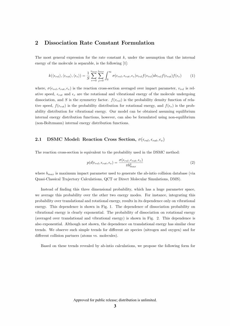
Instead of finding this three dimensional probability, which has a huge parameter space,
we average this probability over the other two energy modes. For instance, integrating this
probability over translational and rotational energy, results in its dependence only on vibrational
energy. This dependence is shown in Fig. 1. The dependence of dissociation probability on
vibrational energy is clearly exponential. The probability of dissociation on rotational energy
(averaged over translational and vibrational energy) is shown in Fig. 2. This dependence is
also exponential. Although not shown, the dependence on translational energy has similar clear
trends. We observe such simple trends for different air species (nitrogen and oxygen) and for
different collision partners (atoms vs. molecules).
Based on these trends revealed by ab-intio calculations, we propose the following form for
Approved for public release; distribution is unlimited.3

p(d|εrel, εrot, εv):
p(d | εrel, εv, εrot) = C1
I︷ ︸︸ ︷[εrel + εint − εd
εd
]αεdεrel
II︷ ︸︸ ︷exp
[βεrotεd
] III︷ ︸︸ ︷exp
[γεvεd
], εrel + εint ≥ εd
= 0, εrel + εint < εd
(3)
where C1 = 7.5× 10⁻³, α = 1.80, β = 0.50, γ = 2.50.
• Term I captures the dependence of dissociation probability on relative translational en-
ergy, with the product of two terms. The first quantifies how far the molecular system
is from the required dissociation energy. The closer it is, the higher the probability, and
vice-versa. The second term appears due to the decrease in probability (reaction-cross
section) when relative translational energy is too high and “fly-by” collisions are more
frequent (Note that α > 1.0).
• Term II quantifies the dependence of dissociation probability on rotational energy with
parameter β.
• Term III quantifies the dependence of dissociation probability on vibrational energy with
parameter γ.
The parameters α, β, and γ, capture the relative importance of translational, rotational, and
vibrational energy for the dissociation probability. The new model results are shown by the lines
in Figs. 1 and 2, where good agreement is seen with the ab-initio cross-section data. Obviously,
the model does not fit the data precisely, however, the reduction of millions of state-to-state
transition probabilities to a simple model function is required for tractable DSMC and CFD
models. In the next section, it will be shown that this probability function allows for analytical
integration in the limit of continuum flow, resulting in a closed-form model for CFD.
Approved for public release; distribution is unlimited.4

εv [eV]
p(d
|εv)
2 4 6 8
105
104
103
102
101
T=13, 000 K
T=20, 000 K
T=30, 000 K
Figure 1: Probability of dissociation as a function of vibrational energy given an average rota-
tional energy and translational temperature (〈εrot〉/kB = T ). The rotational and translational energies are assumed to have Boltzmann distributions (consistent with the underlying QCT data). The new model is shown with solid lines.
rot [eV]
p(d
|ro
t)
0 2 4 6 8 10
104
103
102
101
< v
> = 13, 000 kB
< v
> = 20, 000 kB
< v
> = 30, 000 kB
Figure 2: Probability of dissociation as a function of rotational energy given an average vibra-
tional energy and translational temperature. The translational energies are assumed to have Boltzmann distributions (consistent with the underlying QCT data) at 30, 000 K. The new model is shown with solid lines.
Approved for public release; distribution is unlimited.5
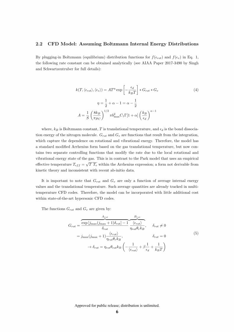
2.2 CFD Model: Assuming Boltzmann Internal Energy Distributions
By plugging-in Boltzmann (equilibrium) distribution functions for f(εrot) and f(εv) in Eq. 1,
the following rate constant can be obtained analytically (see AIAA Paper 2017-3490 by Singh
and Schwartzentruber for full details):
k(T, 〈εrot〉, 〈εv〉) = AT η exp
[− εdkBT
]∗Grot ∗Gv (4)
η =1
2+ α− 1 = α− 1
2
A =1
S
(8kBπµC
)1/2
πb2maxC1Γ[1 + α]
(kBεd
)α−1
where, kB is Boltzmann constant, T is translational temperature, and εd is the bond dissocia-
tion energy of the nitrogen molecule. Grot and Gv are functions that result from the integration,
which capture the dependence on rotational and vibrational energy. Therefore, the model has
a standard modified Arrhenius form based on the gas translational temperature, but now con-
tains two separate controlling functions that modify the rate due to the local rotational and
vibrational energy state of the gas. This is in contrast to the Park model that uses an empirical
effective temperature Teff =√T Tv within the Arrhenius expression; a form not derivable from
kinetic theory and inconsistent with recent ab-initio data.
It is important to note that Grot and Gv are only a function of average internal energy
values and the translational temperature. Such average quantities are already tracked in multi-
temperature CFD codes. Therefore, the model can be incorporated with little additional cost
within state-of-the-art hypersonic CFD codes.
The functions Grot and Gv are given by:
Grot =
Arot︷ ︸︸ ︷exp [jmax(jmax + 1)δrot]− 1
δrot
Brot︷ ︸︸ ︷〈εrot〉
ηrotθrkB, δrot 6= 0
= jmax(jmax + 1)〈εrot〉
ηrotθrkB, δrot = 0
→ δrot = ηrotθrotkB
(− 1
〈εrot〉+ β
1
εd+
1
kBT
)(5)
Approved for public release; distribution is unlimited.6
Gv =
Av︷ ︸︸ ︷exp
[δv2
]1− exp [δvvmax]
1− exp [δv]
Bv︷ ︸︸ ︷1− exp [−θvkB/〈εv〉]exp [−θvkB/(2〈εv〉)]
, δv 6= 0
= vmax1− exp [−θvkB/〈εv〉]exp [−θvkB/(2〈εv〉)]
, δv = 0
→ δv = θvkB
(− 1
〈εv〉+ γ
1
εd+
1
kBT
)(6)
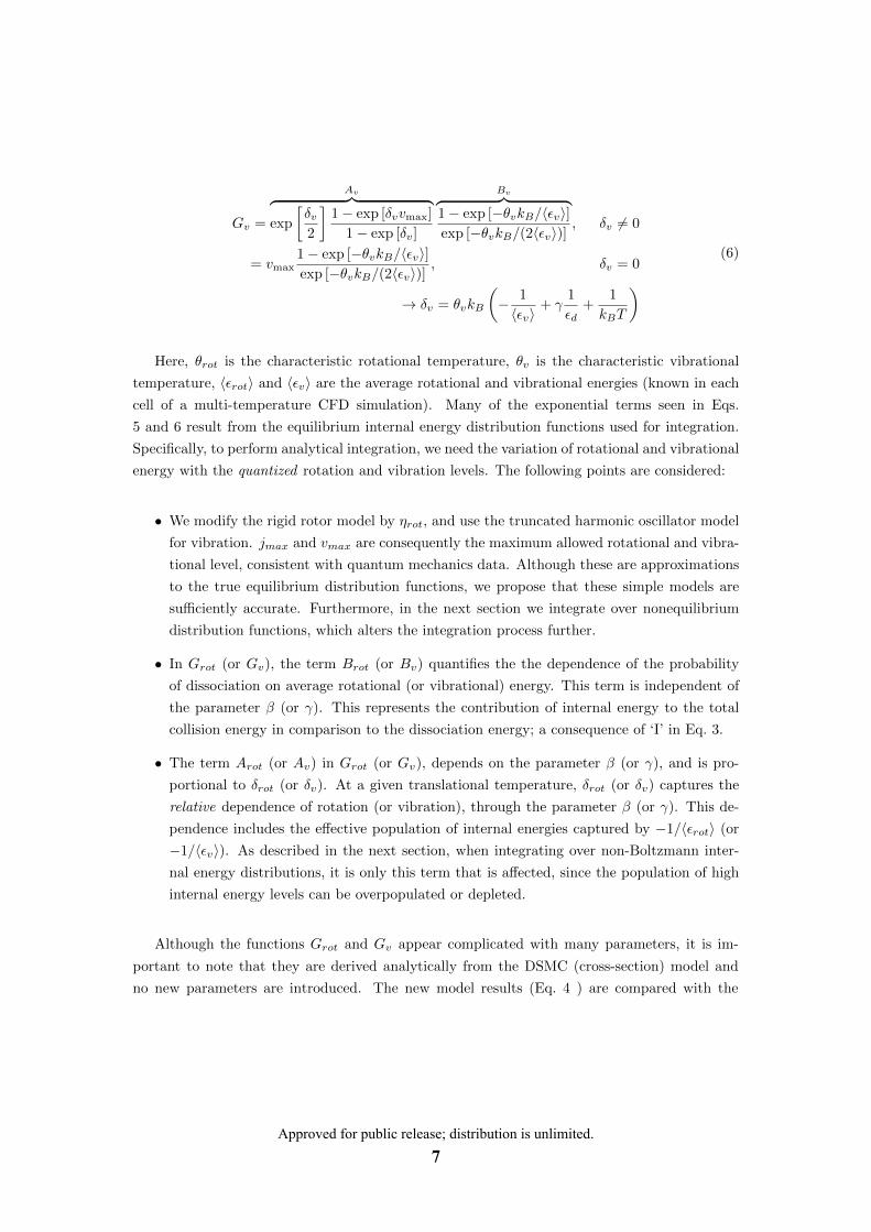
Here, θrot is the characteristic rotational temperature, θv is the characteristic vibrational
temperature, 〈εrot〉 and 〈εv〉 are the average rotational and vibrational energies (known in each
cell of a multi-temperature CFD simulation). Many of the exponential terms seen in Eqs.
5 and 6 result from the equilibrium internal energy distribution functions used for integration.
Specifically, to perform analytical integration, we need the variation of rotational and vibrational
energy with the quantized rotation and vibration levels. The following points are considered:
• We modify the rigid rotor model by ηrot, and use the truncated harmonic oscillator model
for vibration. jmax and vmax are consequently the maximum allowed rotational and vibra-
tional level, consistent with quantum mechanics data. Although these are approximations
to the true equilibrium distribution functions, we propose that these simple models are
sufficiently accurate. Furthermore, in the next section we integrate over nonequilibrium
distribution functions, which alters the integration process further.
• In Grot (or Gv), the term Brot (or Bv) quantifies the the dependence of the probability
of dissociation on average rotational (or vibrational) energy. This term is independent of
the parameter β (or γ). This represents the contribution of internal energy to the total
collision energy in comparison to the dissociation energy; a consequence of ‘I’ in Eq. 3.
• The term Arot (or Av) in Grot (or Gv), depends on the parameter β (or γ), and is pro-
portional to δrot (or δv). At a given translational temperature, δrot (or δv) captures the
relative dependence of rotation (or vibration), through the parameter β (or γ). This de-
pendence includes the effective population of internal energies captured by −1/〈εrot〉 (or
−1/〈εv〉). As described in the next section, when integrating over non-Boltzmann inter-
nal energy distributions, it is only this term that is affected, since the population of high
internal energy levels can be overpopulated or depleted.
Although the functions Grot and Gv appear complicated with many parameters, it is im-
portant to note that they are derived analytically from the DSMC (cross-section) model and
no new parameters are introduced. The new model results (Eq. 4 ) are compared with the
Approved for public release; distribution is unlimited.7
1000 / (<v>/k
B)
k [
cm
3 m
ole
cu
le1 s
1]
0.02 0.04 0.06 0.08 0.1 0.12 0.1410
15
1014
1013
1012
1011
1010
T = 8, 000 K
T = 10, 000 K
T = 13, 000 K
T = 20, 000 K
T = 30, 000 K
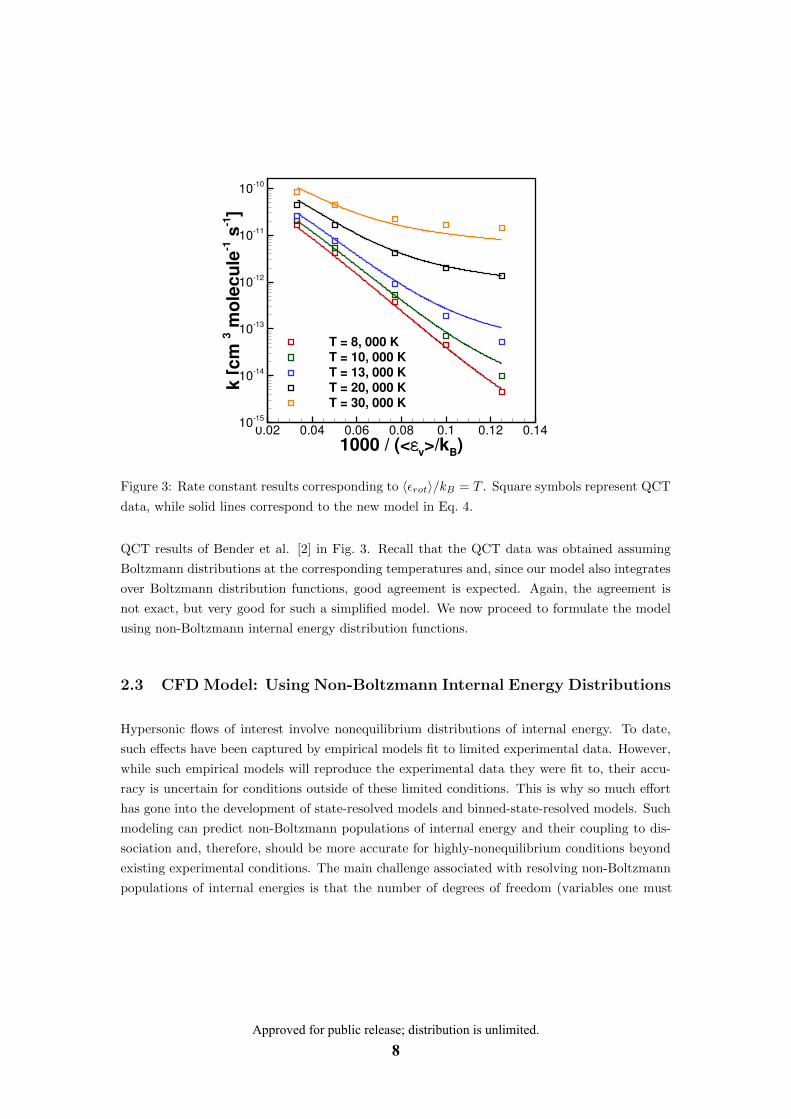
Figure 3: Rate constant results corresponding to 〈εrot〉/kB = T . Square symbols represent QCT
data, while solid lines correspond to the new model in Eq. 4.
QCT results of Bender et al. [2] in Fig. 3. Recall that the QCT data was obtained assuming
Boltzmann distributions at the corresponding temperatures and, since our model also integrates
over Boltzmann distribution functions, good agreement is expected. Again, the agreement is
not exact, but very good for such a simplified model. We now proceed to formulate the model
using non-Boltzmann internal energy distribution functions.
2.3 CFD Model: Using Non-Boltzmann Internal Energy Distributions
Hypersonic flows of interest involve nonequilibrium distributions of internal energy. To date,
such effects have been captured by empirical models fit to limited experimental data. However,
while such empirical models will reproduce the experimental data they were fit to, their accu-
racy is uncertain for conditions outside of these limited conditions. This is why so much effort
has gone into the development of state-resolved models and binned-state-resolved models. Such
modeling can predict non-Boltzmann populations of internal energy and their coupling to dis-
sociation and, therefore, should be more accurate for highly-nonequilibrium conditions beyond
existing experimental conditions. The main challenge associated with resolving non-Boltzmann
populations of internal energies is that the number of degrees of freedom (variables one must
Approved for public release; distribution is unlimited.8

compute and track) becomes quickly intractable. While this research is important, the approach
we have taken with support from this grant is to create a simple model that captures the key
non-Boltzmann effects. The results were recently published in PNAS [5]. Please refer to the
journal article for full details.
To summarize, the key non-Boltzmann physics include: (1) During rapid rovibrational ex-
citation behind a strong shock wave, the high-energy tails of the internal energy distribution
functions become overpopulated compared to the Boltzmann distribution based on the average
energy. (2) During significant dissociation, the high-energy molecules are depleted (due to disso-
ciation) more rapidly than they can be replenished by internal energy excitation. This depletion
reduces the dissociation rate compared to the Boltzmann assumption. These are the two key
physical mechanisms that should be captured by a new dissociation model [3, 4].
Our new model for nonequilibrium internal energy distribution functions is:
f(i) = C1,if0(i)×
Di︷ ︸︸ ︷exp
[−λ1,i
〈εt〉εd
Γi
]×
Oi︷ ︸︸ ︷exp
[−λ2,i
(2
3
〈εt〉〈εi〉− 3
2
〈εi〉〈εt〉
)Γi
],
(7)
where i corresponds to the internal mode (i → v or j), Γv = v, Γj = j(j + 1), and f0(i) is a
Boltzmann distribution. Therefore, both overpopulation (Oi) and depletion (Di) terms model
the departure from an equilibrium (Boltzmann) distribution. We found that these terms can be
accurately modeled as surprisal functions that are linear in v, or j(j + 1).
Specifically, it is the translational energy 〈εt〉/〈εd〉 that controls the depletion due to dissoci-
ation (Di), whereas the energy gap 〈εt〉−〈εi〉 controls the overpopulation during rapid excitation
(Oi). The four model parameters (λ1,i and λ2,i) are used to fit the overpopulation and depletion
of both rotation and vibrational energies, and are determined from the ab initio DMS results.
Now, one can integrate the rate equation using accurate nonequilibrium internal energy
distributions (Eq. 7). The result is the same as that presented above, with only a small change
in the functions Gv and Grot. In fact, only δv and δrot expressions change:
δv = θvkB
[− 1
〈εv〉+ γ
1
εd+
1
kBT+ δNEv
]δNEv = −λ1,v
〈εt〉εd− λ2,v
(2
3
〈εt〉〈εv〉
− 3
2
〈εv〉〈εt〉
)
Approved for public release; distribution is unlimited.9
δrot = ηrotθrotkB
[− 1
〈εrot〉+ β
1
εd+
1
kBT+ δNErot
]δNErot = −λ1,rot
〈εt〉εd− λ2,rot
(2
3
〈εt〉〈εrot〉
− 3
2
〈εrot〉〈εt〉
)
In this manner, the magnitude of Grot and Gv not only adjust the dissociation rate due to
the average rotational and vibrational energy of the gas, but also includes an estimate of the
effect due to non-Boltmzann populations. The model is simple (compared to state-resolved and
binned models), it can fit within a multi-temperature CFD framework, and it is analytically
consistent with the corresponding DSMC model. Notice that by setting δNEi = 0, one recovers
the equilibrium dissociation rate corresponding to Boltzmann internal energy distributions. The
new model parameters (α, β, and γ) capture the relative influence of translation, rotation,
and vibration on dissociation, while the parameters (λ1,i and λ2,i) capture the influence of
overpopulated and depleted high-energy molecules.
3 DSMC and CFD Simulations
3.1 Model Results
In this section we compare DSMC results (using the new model) with the ab-intio Direct Molec-
ular Simulation (DMS) results for the rovibrational excitation and dissociation expected behind
strong shock waves. To summarize, we find existing models cannot predict the DMS results,
whereas our new model very accurately reproduces DMS dissociation results. In the process
we found that the rotational and vibrational energy excitation models also play a crucial role
(more crucial than we had originally expected). Therefore our new dissociation model is a large
improvement, however, it is important to combine with new models for rovibrational relaxation
(on-going).
In Fig. 4 we see that the standard DSMC models (the Total Collision Energy (TCE) model)
gets the rotational and vibrational excitation rates wrong, and also gets the dissociation rate
wrong, compared to the DMS result.
Approved for public release; distribution is unlimited.10

t/
T [
K]
[N2]
/[N
2]0
0 50 100 150 200 2500
5000
10000
15000
20000
25000
0
0.2
0.4
0.6
0.8
1
DMSTCE
Trot
Tvib
Tt
Figure 4: Comparison of a DMS [3] solution with DSMC. For dissociation and excitation, the
TCE model [6] and Millikan and White [7] relaxation times with the high temperature correction
are used. τ is the mean collision time based on the variable hard sphere model.
In Fig. 5, we see that when we adjust the rotational and vibrational excitation rates, to
match DMS, the dissociation rate is still not accurately captured by the standard DSMC TCE
model.
Approved for public release; distribution is unlimited.11

t/
T [
K]
[N2]
/[N
2]0
0 50 100 150 200 2500
5000
10000
15000
20000
25000
0
0.2
0.4
0.6
0.8
1
DMSTCE
TrotTvib
Tt
Figure 5: Comparison of a DMS [3] solution with DSMC. In DSMC, for dissociation and exci-
tation, the TCE model and DMS based [3] characteristic times have been used respectively. τ is mean collision time based on variable hard sphere model.
In Fig. 6, we see that when we use adjusted excitation rates and the new DSMC probability
model, that we now accurately reproduce the ab initio dissociation process. However, note
that we still do not obtain the correct Quasi-Steady-State (QSS). We have determined that
simply “adjusting” the excitation rates to match DMS data is not sufficient. Rather, there is afundamental problem with the standard DSMC internal energy relaxation model that no amount
of adjusting can fix. We are in the process of fixing this problem. We did not fully appreciate
the importance of this, and it is an important outcome of the current research.
Approved for public release; distribution is unlimited.12
t/
T [
K]
[N2]
/[N
2]0
0 50 100 150 200 2500
5000
10000
15000
20000
25000
0
0.2
0.4
0.6
0.8
1
DMSAb initio Model
Trot
Tvib
Tt
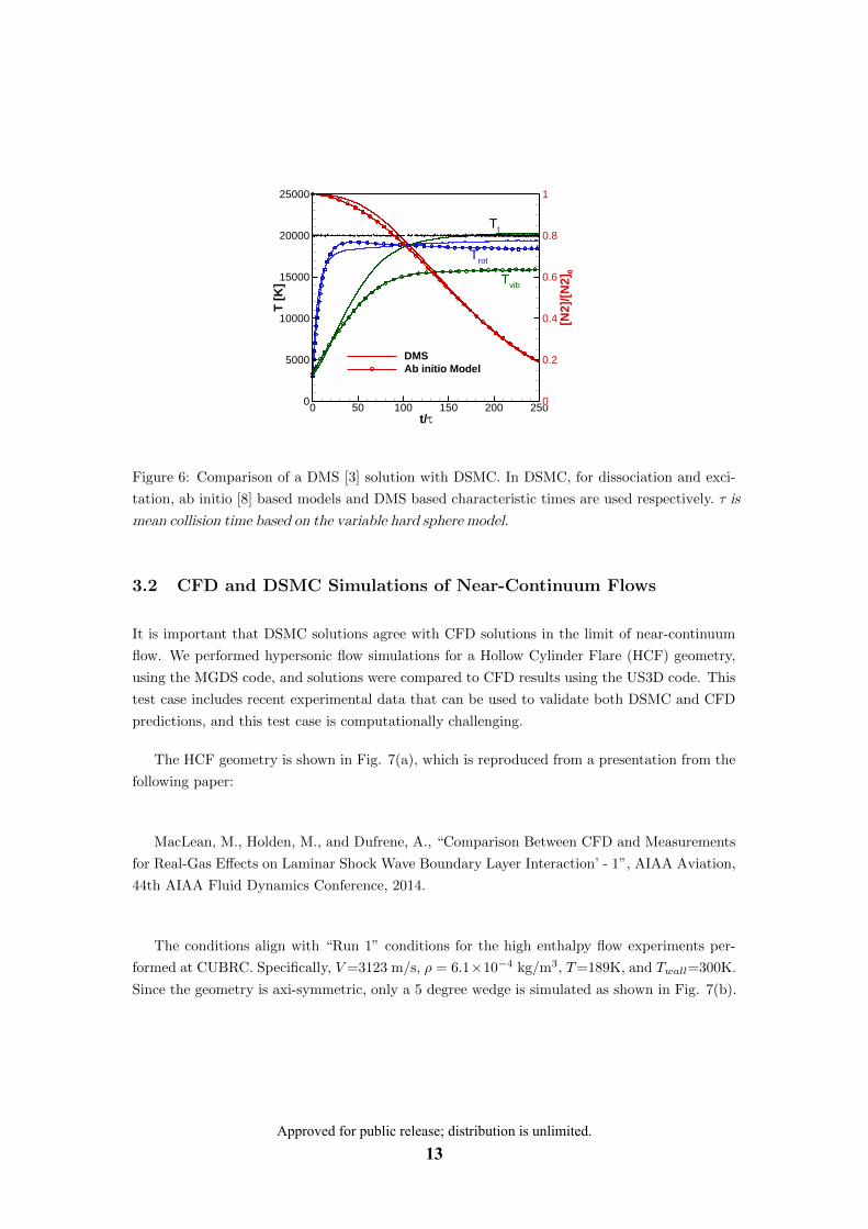
Figure 6: Comparison of a DMS [3] solution with DSMC. In DSMC, for dissociation and exci-
tation, ab initio [8] based models and DMS based characteristic times are used respectively. τ is mean collision time based on the variable hard sphere model.
3.2 CFD and DSMC Simulations of Near-Continuum Flows
It is important that DSMC solutions agree with CFD solutions in the limit of near-continuum
flow. We performed hypersonic flow simulations for a Hollow Cylinder Flare (HCF) geometry,
using the MGDS code, and solutions were compared to CFD results using the US3D code. This
test case includes recent experimental data that can be used to validate both DSMC and CFD
predictions, and this test case is computationally challenging.
The HCF geometry is shown in Fig. 7(a), which is reproduced from a presentation from the
following paper:
MacLean, M., Holden, M., and Dufrene, A., “Comparison Between CFD and Measurements
for Real-Gas Effects on Laminar Shock Wave Boundary Layer Interaction’ - 1”, AIAA Aviation,
44th AIAA Fluid Dynamics Conference, 2014.
The conditions align with “Run 1” conditions for the high enthalpy flow experiments per-
formed at CUBRC. Specifically, V =3123 m/s, ρ = 6.1×10⁻⁴ kg/m3, T =189K, and Twall=300K. Since the geometry is axi-symmetric, only a 5 degree wedge is simulated as shown in Fig. 7(b).
Approved for public release; distribution is unlimited.13

(a) HCF geometry.
(b) DSMC simulation setup.
Figure 7: Hollow cylinder flare geometry and computational setup.
One of the results of the blind code-validation exercise (presented in the above paper) was
that even on the initial cylinder portion of the geometry, the heat flux predicted by CFD codes
did not agree precisely with the experimental data. It was speculated that this could be due
to slip-flow effects. This is the main motivation for the simulations summarized here. As seen
Approved for public release; distribution is unlimited.14

in Fig. 8, the heat flux predicted by DSMC (MGDS) is quite close to that predicted by CFD
(US3D), and both are noticeably lower than the experimental data. It is important to note
that the CFD simulations employed a slip-flow boundary condition. Velocity profiles in the
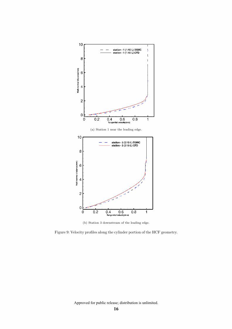
boundary layer are shown at two stations, one near the leading edge of the HCF (Fig. 9(a)) and
downstream of the leading edge (Fig. 9(b)). Both DSMC and CFD predict the same degree
of slip flow. Note that the velocity is scaled by the freestream velocity in these figures. Also,
it is evident that the degree of slip flow decreases as distance from the leading edge increases
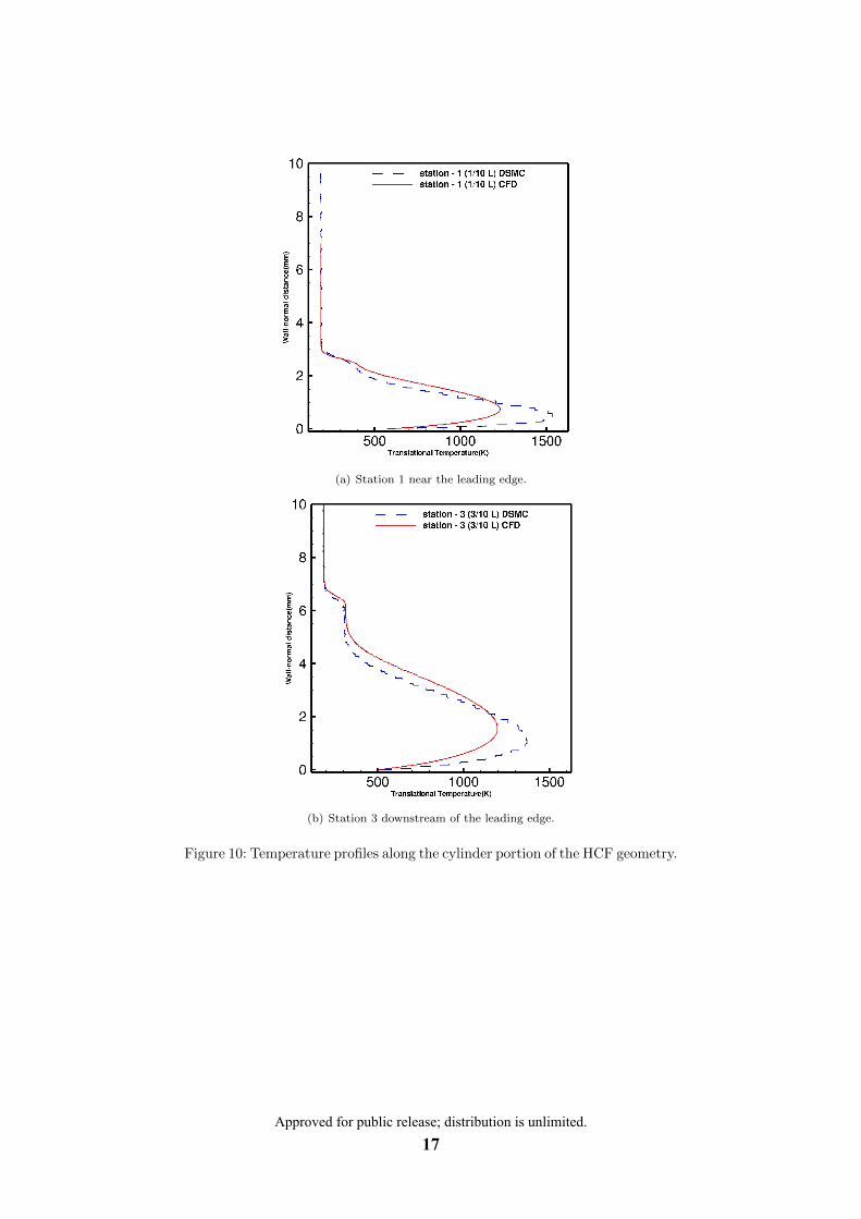
(station 3 vs. station 1). The temperature profiles at the same stations are shown in Figs.
10(a) and 10(b). A temperature jump is predicted by both DSMC and CFD, which diminishes
as distance downstream increases. Here, more noticeable differences are seen in the boundary
layer, however, as seen in the heat flux result (Fig. 8), these differences have little effect on the
net heat flux to the surface. Therefore, differences in the boundary layer are evident between
DSMC and CFD as expected for this near-continuum flow, however, the net effect on the surface
is negligible and both methods are in close agreement.
Figure 8: Heat flux along the initial cylinder portion of the HCF.
Full details of this research, were presented at the AIAA SciTech conference in January of
2018 (refer to publication listing in the introduction).
Approved for public release; distribution is unlimited.15
(a) Station 1 near the leading edge.
(b) Station 3 downstream of the leading edge.
Figure 9: Velocity profiles along the cylinder portion of the HCF geometry.
Approved for public release; distribution is unlimited.16
(a) Station 1 near the leading edge.
(b) Station 3 downstream of the leading edge.
Figure 10: Temperature profiles along the cylinder portion of the HCF geometry.
Approved for public release; distribution is unlimited.17

References
[1] J. T. Muckerman, D. G. Truhlar, and R. B. Bernstein, Atom–Molecule Collision Theory: A Guide for the Experimentalist, Plenum, New York, 1979.
[2] Jason D. Bender, Paolo Valentini, Ioannis Nompelis, Yuliya Paukku, Zoltan Varga, Donald G. Truhlar, Thomas Schwartzentruber, and Graham V Candler, "An Improved Potential Energy Surface and Multi-Temperature Quasiclassical Trajectory Calculations of N2+ N2 Dissociation Reactions," The Journal of Chemical Physics, 143(5):054304, 2015.
[3] Paolo Valentini, Thomas E. Schwartzentruber, Jason D. Bender, and Graham V. Candler, "Dynamics of Nitrogen Dissociation from Direct Molecular Simulation," Physical Review Fluids, 1(4):043402, 2016.
[4] Paolo Valentini, Thomas E. Schwartzentruber, Jason D. Bender, Ioannis Nompelis, and Graham V. Candler, "Direct Molecular Simulation of Nitrogen Dissociation Based on an ab initio Potential Energy Surface," Physics of Fluids, 27(8):086102, 2015.
[5] Narendra Singh and Thomas Schwartzentruber, "Nonequilibrium Internal Energy Distributions During Dissociation," Proceedings of the National Academy of Sciences, 115(1):47–52, 2018.
[6] G. A. Bird, "Monte-Carlo Simulation in an Engineering Context," Progress in Astronautics and Aeronautics, 74:239–255, 1981.
[7] Roger C. Millikan and Donald R. White, "Systematics of Vibrational Relaxation," The Journal of Chemical Physics, 39(12):3209–3213, 1963.
[8] Narendra Singh and Thomas E. Schwartzentruber, "Coupled Vibration-Rotation Dissociation Model for Nitrogen from Direct Molecular Simulations," In 47th AIAA Thermophysics Conference, Denver, CO, p. 3490, 2017.
Approved for public release; distribution is unlimited.18

DISTRIBUTION LIST
1 cy
1 cy
DTIC/OCP 8725 John J. Kingman Rd, Suite 0944 Ft Belvoir, VA 22060-6218
AFRL/RVIL Kirtland AFB, NM 87117-5776
Official Record Copy AFRL/RVBY/Dr. Thomas Fraser 1 cy
Approved for public release; distribution is unlimited.19

This page is intentionally left blank.
Approved for public release; distribution is unlimited.20


![A Two-Temperature Open-Source CFD Model for Hypersonic ... · hypersonic bodies. The direct simulation Monte Carlo (DSMC) method developed by Bird [1] is a particle-based methodology](https://img.dokumen.tips/doc/110x75/5ea149538a790a4f56246968/a-two-temperature-open-source-cfd-model-for-hypersonic-hypersonic-bodies-the.jpg)