Embed Size (px)
Citation preview

Demo Lab Guide – OS 9 Emulator
Quick Start Guide – Example OSPF Configuration
Product Domain: Networking
Author: Ruairi Mongan
Version: 1.01 Date: 01/01/2016

Table of Contents 1 Product Overview ............................................................................................................................................ 3
1.1 Lab Preparation Considerations and Caveats .................................................................................. 3
2 Introduction ..................................................................................................................................................... 4
2.1 Lab Topology and Essential Information ......................................................................................... 4
2.1.1 Supported Features .............................................................................................................................. 5
2.1.2 Lab Addressing and Login Details ...................................................................................................... 5
2.1.3 Element Access .................................................................................................................................... 6
3 OSPF – Using OS 9 Emulator Example ...................................................................................................... 9
3.1 How to use the Emulator Environment ........................................................................................... 9
3.1.1 Pre-requisite Information ................................................................................................................. 10
3.1.2 Configure and Test OSPF using Emulator ..................................................................................... 10
4 Summary .........................................................................................................................................................27

3 Dell Demo Center – https://demos.dell.com | Dell Inc., 2016
1 Product Overview
The Dell Networking Operating System (OS) Emulator is a virtualized environment where you can create
simple network topologies and test various features of the Dell Networking OS. The virtual environment
allows you to get familiar with the command line interface (CLI) without having access to a physical
device.
Note: The Dell Networking Emulator is not intended to provide a complete emulation of a Dell switch
hardware. It can only supplement, but not replace, training or testing on physical devices
1.1 Lab Preparation Considerations and Caveats
It is in your best interests to ensure the demo environment you will be demonstrating is clean & tidy
before you begin. For this reason we would recommend, where possible, you log in to your demo at
least 15 minutes prior to delivery and check the following;
1. Familiarize yourself with the environment during this time and check any specific features
you are expecting to demo.
2. Most importantly, be crystal clear with yourself on what it is you plan to show. A full demo
of every feature described below (with questions) can take several hours. If you only have a
short time slot be sure to focus on the key points that address the customer’s pain points
and will drive value home to them.
3. Ensure that you have scheduled the demo for sufficient time so as not to have the demo
end before you are finished with the customer.

4 Dell Demo Center – https://demos.dell.com | Dell Inc., 2016
2 Introduction
In this guide you will find the OS 9 Emulator demo that is available through https://demos.dell.com The
guide details the demo options available to the user enabling the demonstration and learning of Dell
OS 9. The guide provides steps by step instruction on how to setup up the emulator and offers an
example configuration scenario as part of the setup.
The guide and demo are focused on the following elements:-
Providing a facility to enable engineers to learn the OS 9 command structure and the various
configuration options
Provides and example setup on how to use the OS 9 emulator
2.1 Lab Topology and Essential Information
The diagram provides detail on the setup of the demonstration environment. The environment
provided is self-contained and has a number of virtual machines images provided for use.

5 Dell Demo Center – https://demos.dell.com | Dell Inc., 2016
The environment consists of:
- 1 x ESX server
- 1 x vCenter Server
- 1 x OS 9 Emulator template
- 1 x Windows 7 template
2.1.1 Supported Features The Dell Networking Emulator supports the following features:
- Up to five data ports and one management port (five 40G or 10G ports)
- All management-related protocols and features such as simple network management protocol
(SNMP), telnet, secure shell (SSH)
- Layer 1 link up/down status when connected to another Dell Networking OS instance
- Optics emulation
- Layer 3 features such as routing and forwarding
- Routing protocols such as border gateway protocol (BGP), open shortest path first (OSPF),
intermediate system to intermediate system (ISIS), and routing information protocol (RIP)
- Management functionalities such as dynamic host configuration protocol (DHCP), Smartscripts,
authentication, authorization, and accounting (AAA), remote authentication dial-in user service
(RADIUS), terminal access controller access control system (TACACS+), management plane
isolation
- Flash and nonvolatile random access memory (NVRAM)
- 40G and 10G interfaces
- Limited Layer 2 functionality such as LLDP, LACP
2.1.2 Lab Addressing and Login Details Please pay attention to the ip addressing and login details provided. These are essential for the
successful completion of the lab. The information will be required during various phases on of the lab.
The following tables provides ip addressing and login credentials for all elements needed to complete
the lab:
Hostname Username Password Management Network
Default Gateway
Emulator Template
Not set Password (also enable password)
Not Defined Not Defined
Windows 7 Template
demouser password Not Defined Not Defined
vCenter root Root 192.168.1.12/24 Not Defined
ESX host root password 192.168.1.10/24 Not Defined
6 Dell Demo Center – https://demos.dell.com | Dell Inc., 2016
2.1.3 Element Access
Once you have selected and launched the URL link provided via your demo booking e-mail you will be
logged into your environment. On the desktop of the demo machine please check and ensure there is
a shortcut for the VMware vSphere client. You will be using the client throughout the demo to access
the emulator and windows 7 virtual machines. The desktop should look similar to the image below:-
To access the environment please launch the VMware vSphere client from the shortcut provided on the
desktop.
When the client has launched please enter the vCenter username and password provided on the Demo
Homepage.

7 Dell Demo Center – https://demos.dell.com | Dell Inc., 2016
Note: The ip address should be left as the default that appears when the vSphere Client is launched.
Once logged into the environment expand the “Templates” resource pool. In the resource pool there
are two virtual machines:
There machines are labelled:
- emulator-template
- win7-template
The “emulator template” has been pre-configured with a management interface and six data ports.
During the example walk-through we will create various vswitches to enable the completion of the
scenario in the following steps. This information can be view under the “Resources” section on the
“Summary” view of the virtual machine:

9 Dell Demo Center – https://demos.dell.com | Dell Inc., 2016
3 OSPF – Using OS 9 Emulator Example
3.1 How to use the Emulator Environment
The following scenario will walk through an example of how the environment provided can be used for
learning and customer demonstration purposes. It will provide step by step detail on how to set up and
configure the emulator and interact with the emulator and windows 7 virtual machines through the
VMware vSphere client.
Note: This example is provided as a guide on how the emulator can be used. It does not cover all the
capabilities available within the OS 9 emulator. If you would like to try other features of OS 9 within
this environment please consult the OS 9 product and administration guides available at
https://support.dell.com
Note: The release notes for the emulator are provided with the environment. These can be used to
explore and understand the more advanced configurations.
The demonstration scenario we are going to deploy is a simple OSPF configuration. We will test the
setup by attaching a VM on a port of each emulator and routing traffic between the two VM’s. Please
see the diagram below detailing the setup we will build:

10 Dell Demo Center – https://demos.dell.com | Dell Inc., 2016
3.1.1 Pre-requisite Information
The table below details the ip addressing needed to complete the configuration steps that follow. Please
reference this table when configure the ip interfaces on the routers and test vm’s.
Note: The ip addressing scheme used in the example does not need to be followed. It is at your
discretion what scheme to use.
Hostname Interface Forty 0/0 IP Addressing
Interface Forty 0/4 IP Addressing
Local Area Connection
Default Gateway
EM-ROUTER01
172.16.10.1/30 192.168.10.1/24 N/A
EM-ROUTER02
172.16.10.2/30 192.168.11.1/24 N/A
Client 01 N/A N/A 192.168.10.2/24 192.168.10.1
Client 02 N/A N/A 192.168.11.2/24 192.168.11.2
3.1.2 Configure and Test OSPF using Emulator
The following section will walk-through the various tasks needed to complete the setup. Let’s get
started.
1. To complete the necessary configuration we will need to clone two copies of the emulator-
template and two copies of the win7-template” vm. The following sections will outline the steps
required.
Note: An example of cloning the emulator machine is shown. Please repeat the steps for the
additional emulator vm and two windows 7 vm’s.
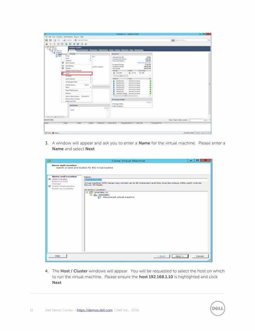
2. Right click on the emulator-template vm and select Clone
11 Dell Demo Center – https://demos.dell.com | Dell Inc., 2016
3. A window will appear and ask you to enter a Name for the virtual machine. Please enter a
Name and select Next
4. The Host / Cluster windows will appear. You will be requested to select the host on which
to run the virtual machine. Please ensure the host 192.168.1.10 is highlighted and click
Next

12 Dell Demo Center – https://demos.dell.com | Dell Inc., 2016
5. the Resource Pool window will appear please accept the default and click Next
6. The Storage window will appear. Please ensure the settings are the same as those in the
image below. Once completed click Next
7. The Guest Customization window appears please accept the default here and select Next
8. The Ready to Complete windows appears. Review the configuration and select Finish

13 Dell Demo Center – https://demos.dell.com | Dell Inc., 2016
9. Check the Recent Task at the bottom of the vSphere Client window to ensure it has
completed successfully.
10. Once the task has complete successfully please Power On the new virtual machine.
Note: Please repeat the previous steps for the reaming three virtual machines. Allow a little time for
the clone operations to complete before powering on the windows 7 machines. You can proceed on
to the next tasks while the clone operation on the windows 7 machines complete.

14 Dell Demo Center – https://demos.dell.com | Dell Inc., 2016
11. Now the virtual machines have been created and powered on we will need to create the
necessary virtual switches to allow communication between the various components within
our setup. For the setup to work the environment requires the creation of three vSwitches:
i. One for communication between the routers
ii. One for communication between each windows 7 vm and its local router
b. From within the vSphere Client select the host and the Configuration tab and
Networking
i. Select and Add Networking

15 Dell Demo Center – https://demos.dell.com | Dell Inc., 2016
c. The Add Networking Wizard appears. Under Connections Types select Virtual
Machine and click Next
i. Ensure Create a vSphere standard switch is selected and click Next
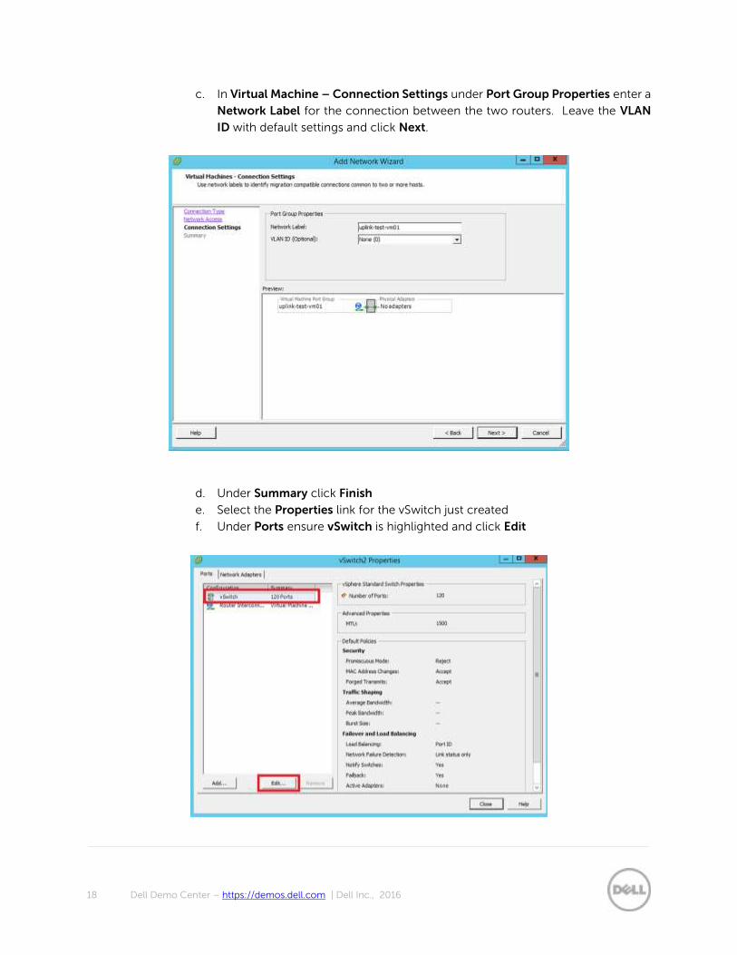
ii. In Virtual Machine – Connection Settings under Port Group Properties
enter a Network Label for the connection between the two routers. Leave
the VLAN ID with default settings and click Next

16 Dell Demo Center – https://demos.dell.com | Dell Inc., 2016
iii. Under Summary click Finish
iv. Select the Properties link for the vSwitch just created
v. Under Ports ensure vSwitch is highlighted and click “Edit”
vi. Select the Security tab
vii. Under Policy Exceptions ensure the three options are set to Accept as in
the image below:
viii. Click OK

17 Dell Demo Center – https://demos.dell.com | Dell Inc., 2016
ix. Click Yes
x. Click Close
d. Next we need to add the two routers to the “Router Interconnection” port group
on the new vSwitch.
i. Select EM-ROUTER01
ii. On the Summary Tab select Edit Settings
iii. Highlight “Network adapter 2” and under the Network Connection drop
down on the right-hand side ensure Network Label is set to Router
Interconnection
Note: repeat these three steps for EM-Router02
iv. Click OK
12. Next we need to define the vswitch settings for each connection between the local router
and the test vm. These steps show the setup for EM-ROUTER01 and test-vm01.
Note: Please repeat these steps for EM-ROUTER02 and test-vm02
a. The Add Networking Wizard appears. Under Connections Types select Virtual
Machine and click Next
b. Ensure Create a vSphere standard switch is selected and click Next
18 Dell Demo Center – https://demos.dell.com | Dell Inc., 2016
c. In Virtual Machine – Connection Settings under Port Group Properties enter a
Network Label for the connection between the two routers. Leave the VLAN
ID with default settings and click Next.
d. Under Summary click Finish
e. Select the Properties link for the vSwitch just created
f. Under Ports ensure vSwitch is highlighted and click Edit

19 Dell Demo Center – https://demos.dell.com | Dell Inc., 2016
g. Select the Security tab
h. Under Policy Excpetions ensure the three options are set to Accept as in the
image below:
i. Click OK
j. Click Yes
k. Click Close
13. Next we need to add the EM-ROUTER01 and test-vm01 to the uplink-to-test-vm01 port
group on the new vSwitch.
a. Select EM-ROUTER01
b. On the Summary Tab select Edit Settings
c. Highlight Network adapter 3 and under the Network Connection drop down
on the righthand side ensure Network Label is set to Router Interconnection
Note: repeat these three steps for EM-Router02
d. Click OK
e. Select test-vm01
f. On the Summary Tab select Edit Setting
g. Highlight Network adapter 1 and under the Network Connection drop down
on the right-hand side ensure Network Label is set to uplink-to-test-vm01
Note: repeat these steps for EM-Router02 and test-vm02
h. Click OK

20 Dell Demo Center – https://demos.dell.com | Dell Inc., 2016
14. Now the vm’s have been created and powered on the next stage is applying the necessary
configurations to the emulator vm’s and the windows 7 vm’s to enable communication
across the network. The following steps outline the configuration that needs to be applied:
a. We will start the EM-ROUTER01
i. Launch the console window of EM-ROUTER01 to start the configuration
ii. A window will launch providing access to the EM-ROUTER01 command
line.

21 Dell Demo Center – https://demos.dell.com | Dell Inc., 2016
iii. When the console window appears please click in the window and press
return. A prompt will appear. Press A to abort BMP mode.
iv. A warning will appear [A/C/L/S]:% Warning: The bmp process will stop ….
When the process have stop press “Return” to enter into the emulator
command prompt.

22 Dell Demo Center – https://demos.dell.com | Dell Inc., 2016
v. Now we will enter into configuration mode and change the hostname of
the emulator.
Dell#config
Dell(conf)#hostname EM-ROUTER01
vi. Next we will configure the interfaces required for communication with the
local windows 7 client (test-vm01) and EM-ROUTER01 and between EM-
ROUTER01 and EM-ROUTER02. Please enter the following commands in
configuration mode:
EM-ROUTER01(conf)#inter for 0/0
EM-ROUTER01(conf-if-fo-0/0)#description uplink-to-EM-ROUTER02
EM-ROUTER01(conf-if-fo-0/0)#ip address 172.16.10.1/30
EM-ROUTER01(conf-if-fo-0/0)#no shutdown
EM-ROUTER01(conf-if-fo-0/0)#interface for 0/4
EM-ROUTER01(conf-if-fo-0/4)# description uplink-to-test-vm01
EM-ROUTER01(conf-if-fo-0/4)# ip address 192.16.10.1/24
EM-ROUTER01(conf-if-fo-0/4)#no shutdown
EM-ROUTER01(conf-if-fo-0/4)#no keepalive
Note: Please repeat the sub items contained in step number 3 for router EM-ROUTER02. The ip
addressing details for router EM-ROUTER02 can be found in the Demo Example section at the start
of the document.
15. Once the configuration has been applied to the routers we need to configure the OSPF
settings to enable dynamic routing. Please enter configuration mode on EM-ROUTER01
and EM-ROUTER02
a. Apply the following configuration to “M-ROUTER01
EM-ROUTER01(conf)#router ospf 1
EM-ROUTER01(conf-router_ospf-1)#router-id 1.1.1.1
EM-ROUTER01(conf-router_ospf-1)#network 172.16.10.0/30 area 0
EM-ROUTER01(conf-router_ospf-1)#network 192.168.10.0/24 area 0
b. Apply the following configuration to EM-ROUTER02
EM-ROUTER02(conf)#router ospf 1
EM-ROUTER02(conf-router_ospf-1)#router-id 1.1.1.2
EM-ROUTER02(conf-router_ospf-1)#network 172.16.10.0/30 area 0
EM-ROUTER02(conf-router_ospf-1)#network 192.168.11.0/24 area 0

23 Dell Demo Center – https://demos.dell.com | Dell Inc., 2016
c. You can check that OSPF in configured correctly by running the following
commands on both routers and reviewing the output. If successful the output
show look similar to the images below.
EM-ROUTER01# show ip ospf neighbor
EM-ROUTER01# show ip route

24 Dell Demo Center – https://demos.dell.com | Dell Inc., 2016
16. Now the router configuration is complete the next step is to apply the necessary network
configuration for test-vm01 and test-vm02. The addressing information can be found in
the table at the start of the guide. Launch the test-vm01 console window
a. From within the vm console window launch Control Panel > All Control Panel
Items > Networking and Sharing Center
b. Select the Change adapter settings

25 Dell Demo Center – https://demos.dell.com | Dell Inc., 2016
c. Right click on the Local Area Connection and select Properties
d. Select Internet Protocol Version 4 (TCP/IPv4) and Properties
e. A properties window appears. Select Use the following IP address: and enter
the ip address information relevant for the vm. These can be found at the
beginning of the guide
f. Please repeat the process for test-vm02 apply the correct ip addressing details
to its network interface.

26 Dell Demo Center – https://demos.dell.com | Dell Inc., 2016
17. Now all the necessary configuration has been applied to the routers and test vm’s we can
validate our routing configuration is correct. To test the configuration works correctly
please go to the vSphere Client Console on test-vm01
a. Open a command prompt and enter a ping command that trys to get a response
from test-vm02 e.g. ping 192.168.11.2 If the lab is configured correctly you will
get a response from the ip interface on test-vm02.

27 Dell Demo Center – https://demos.dell.com | Dell Inc., 2016
4 Summary
You have now successfully configured a network using the OS 9 emulator. This demonstrates an
example use case of the OS 9 emulator. There are many more capabilities not covered in this quick
start guide. It primarily meant to showcase the possibilities that are open to you. We hope this short
example has been beneficial and gives you and insight into what is possible with the emulator.
The emulator environment has been provided for learning and demonstration purposes. Please explore
some more of the advanced capabilities of the product.