Embed Size (px)
Citation preview
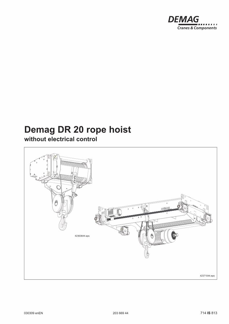
Demag DR 20 rope hoistwithout electrical control
030309 enEN 203 669 44 714 IS 813
42363644.eps
42371044.eps
2 2036
6944
.indd
/030
309
Manufacturer Demag Cranes & Components GmbHP.O. Box 67, D-58286 WetterTelephone +49 (0) 2335 92-0 · Telefax +49 (0) 2335 927676www.demagcranes.com
Please fill in the following table before first putting the chain hoist into service.This provides you with a definitive documentation of your Demag rope hoist and important information if you ever have to contact the manufacturer or his representative.
Owner
Where in use
Range
Serial number
Main hoist motor number
Operating voltage
Control voltage
Frequency
Wiring diagram number
Accompanying documents
Operating instructions
Demag FDR 20 rope hoist 214 840 44 720 IS 813
Demag EZDR 20 rope hoist 214 844 44 720 IS 813
Dedrive Compact DIC (Brief operating instructions) 214 708 44 720 IS 922
Application guidelines / operating instructions Dedrive Compact DIC 214 716 44 720 IS 922
CD Dedrive Compact DIC 213 136 44 716 IS 922
External pulse encoder 214 372 44 720 IS 919
Z motor range 214 228 44 720 IS 919

32036
6944
.indd
/030
309
This document contains information on rope hoists without electrical control. They apply to FDR 20 and EZDR 20.
Depending on the type, the standard scope of delivery includes:
- 12/2-pole hoist motor with Microtherm and AG integrated pulse generator- GS and VE brake modules - 4-pole hoist motor with Microtherm and mechanical mounting device for
AG 1 - 3 external pulse generators- GS and VE brake modules- 4-pole cross-travel motor with Microtherm- GE and VE brake modules- Electrical housing with base plate for connecting the sensors- SGG geared limit switch- MGS overload protection; for double-groove design with ZMS
Pay attention to the following when designing the electrical equipment for DR rope hoists not supplied with electrical equipment:Pole-changing motors are rated for intermittent duty. The basis for this is FEM 9.683, issue 10/1995Derived from this document, we provide values for the duty factor and switching frequency for these motors in our documentation.The specified values must not be exceeded. In order to ensure this, we recom-mend that timing elements be incorporated in the control system to prevent too frequent switching or too fast restoration of the supply to the two-pole winding. The value should be set to at least 1 second.For setting up the electronic circuit, the SGDM hoist unit relay must be used for this function.
Introduction
4 2036
6944
.indd
/030
309
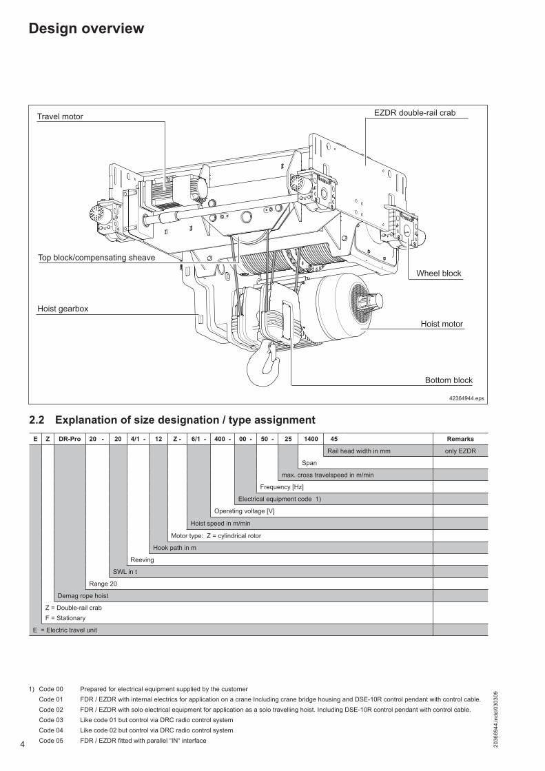
42364944.eps
Bottom block
Travel motor
Hoist gearbox
EZDR double-rail crab
Hoist motor
Wheel block
Top block/compensating sheave
Design overview
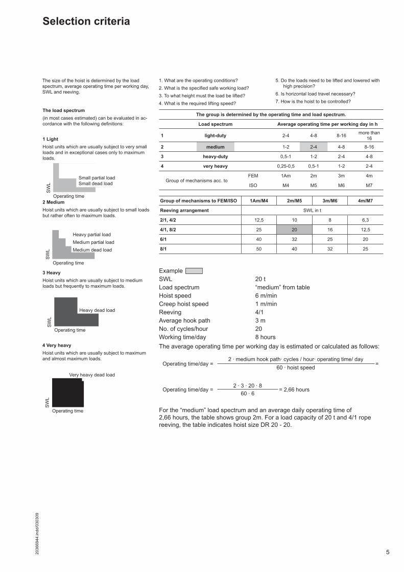
2.2 Explanation of size designation / type assignment
1) Code 00 Prepared for electrical equipment supplied by the customer Code 01 FDR / EZDR with internal electrics for application on a crane Including crane bridge housing and DSE-10R control pendant with control cable. Code 02 FDR / EZDR with solo electrical equipment for application as a solo travelling hoist. Including DSE-10R control pendant with control cable. Code 03 Like code 01 but control via DRC radio control system Code 04 Like code 02 but control via DRC radio control system Code 05 FDR / EZDR fitted with parallel “IN“ interface
E Z DR-Pro 20 - 20 4/1 - 12 Z - 6/1 - 400 - 00 - 50 - 25 1400 45 Remarks
Rail head width in mm only EZDR
Span
max. cross travelspeed in m/min
Frequency [Hz]
Electrical equipment code 1)
Operating voltage [V]
Hoist speed in m/min
Motor type: Z = cylindrical rotor
Hook path in m
Reeving
SWL in t
Range 20
Demag rope hoist
Z = Double-rail crabF = Stationary
E = Electric travel unit
52036
6944
.indd
/030
309
Example SWL 20 tLoad spectrum “medium” from tableHoist speed 6 m/minCreep hoist speed 1 m/minReeving 4/1Average hook path 3 mNo. of cycles/hour 20Working time/day 8 hoursThe average operating time per working day is estimated or calculated as follows:
The size of the hoist is determined by the load spectrum, average operating time per working day, SWL and reeving.
SW
L
Operating time
SW
L
Operating time
SW
L
Operating time
Operating time
Very heavy dead load
Small partial loadSmall dead load
Heavy partial loadMedium partial loadMedium dead load
Heavy dead load
SW
L
4 Very heavyHoist units which are usually subject to maximum and almost maximum loads.
3 HeavyHoist units which are usually subject to medium loads but frequently to maximum loads.
2 MediumHoist units which are usually subject to small loads but rather often to maximum loads.
The load spectrum(in most cases estimated) can be evaluated in ac-cordance with the following definitions:
1 LightHoist units which are usually subject to very small loads and in exceptional cases only to maximum loads.
Selection criteria
1. What are the operating conditions?2. What is the specified safe working load?3. To what height must the load be lifted?4. What is the required lifting speed?
5. Do the loads need to be lifted and lowered with high precision?
6. Is horizontal load travel necessary?7. How is the hoist to be controlled?
For the “medium” load spectrum and an average daily operating time of 2,66 hours, the table shows group 2m. For a load capacity of 20 t and 4/1 rope reeving, the table indicates hoist size DR 20 - 20.
The group is determined by the operating time and load spectrum.
Load spectrum Average operating time per working day in h
1 light-duty 2-4 4-8 8-16 more than 16
2 medium 1-2 2-4 4-8 8-16
3 heavy-duty 0,5-1 1-2 2-4 4-8
4 very heavy 0,25-0,5 0,5-1 1-2 2-4
Group of mechanisms acc. to FEM 1Am 2m 3m 4m
ISO M4 M5 M6 M7
Group of mechanisms to FEM/ISO 1Am/M4 2m/M5 3m/M6 4m/M7
Reeving arrangement SWL in t
2/1, 4/2 12,5 10 8 6,3
4/1, 8/2 25 20 16 12,5
6/1 40 32 25 20
8/1 50 40 32 25
Operating time/day =2 · medium hook path· cycles / hour· operating time/ day
=60 · hoist speed
Operating time/day =2 · 3 · 20 · 8
= 2,66 hours60 · 6
6 2036
6944
.indd
/030
309
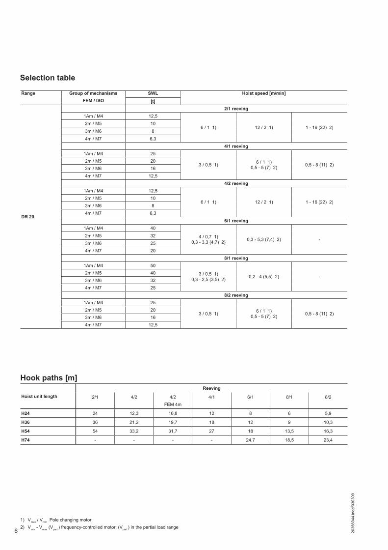
Hoist unit length
Reeving
2/1 4/2 4/2 FEM 4m
4/1 6/1 8/1 8/2
H24 24 12,3 10,8 12 8 6 5,9
H36 36 21,2 19,7 18 12 9 10,3
H54 54 33,2 31,7 27 18 13,5 16,3
H74 - - - - 24,7 18,5 23,4
Hook paths [m]
Selection table
1) Vmax / Vmin Pole changing motor2) Vmin - Vmax (Vpart ) frequency-controlled motor; (Vpart ) in the partial load range
Range Group of mechanismsFEM / ISO
SWL Hoist speed [m/min]
[t]
DR 20
2/1 reeving1Am / M4 12,5
6 / 1 1) 12 / 2 1) 1 - 16 (22) 2)2m / M5 10
3m / M6 8
4m / M7 6,34/1 reeving
1Am / M4 25
3 / 0,5 1) 6 / 1 1) 0,5 - 5 (7) 2) 0,5 - 8 (11) 2)
2m / M5 203m / M6 164m / M7 12,5
4/2 reeving1Am / M4 12,5
6 / 1 1) 12 / 2 1) 1 - 16 (22) 2)2m / M5 103m / M6 84m / M7 6,3
6/1 reeving1Am / M4 40
4 / 0,7 1)0,3 - 3,3 (4,7) 2) 0,3 - 5,3 (7,4) 2) -
2m / M5 323m / M6 254m / M7 20
8/1 reeving1Am / M4 50
3 / 0,5 1)0,3 - 2,5 (3,5) 2) 0,2 - 4 (5,5) 2) -
2m / M5 403m / M6 324m / M7 25
8/2 reeving1Am / M4 25
3 / 0,5 1) 6 / 1 1)0,5 - 5 (7) 2) 0,5 - 8 (11) 2)
2m / M5 203m / M6 164m / M7 12,5

72036
6944
.indd
/030
309
Motor selection depending on the reeving and SWL
Motor selection for pole-changing hoist drivesMain/creep lifting F6
Reeving 2/1 and 4/2 4/1 and 8/2
Hoist speed [m/min] 6/1 12/2 3/0,5 6/1
FEM/ISO Group of mechanisms
1Am/M4
2m/M5
3m/M6
4m/M7 1Am/M4 2m/
M53m/M6
4m/M7
1Am/M4
2m/M5
3m/M6
4m/M7 1Am/M4 2m/
M53m/M6
4m/M7
MotorZBR 180 A
12/215/25% CDF
ZBR 132 D12/2
20/40% CDF
ZBR 200 B12/2
15/25% CDF
ZBR 200 B12/2
20/40% CDF
ZBR 180 A12/2
15/25% CDF
ZBR 132 D12/2
20/40% CDF
ZBR 200 B12/2
15/25% CDF
ZBR 200 B12/2
20/40% CDF
SWL 12,5 10 8 6,3 12,5 10 8 6,3 25 20 16 12,5 25 20 16 12,5
Reeving 6/1 8/1
Hoist speed [m/min] 4/0,7 3/0,5
FEM/ISO Group of mechanisms 1Am/M4 2m/M5 3m/M6 4m/M7 1Am/M4 2m/M5 3m/M6 4m/M7
MotorZBR 200 B
12/215/25% CDF
ZBR 200 B12/2
20/40% CDF
ZBR 200 B12/2
15/25% CDF
ZBR 200 B12/2
20/40% CDF
SWL 40 32 25 20 50 40 32 25
8 2036
6944
.indd
/030
309
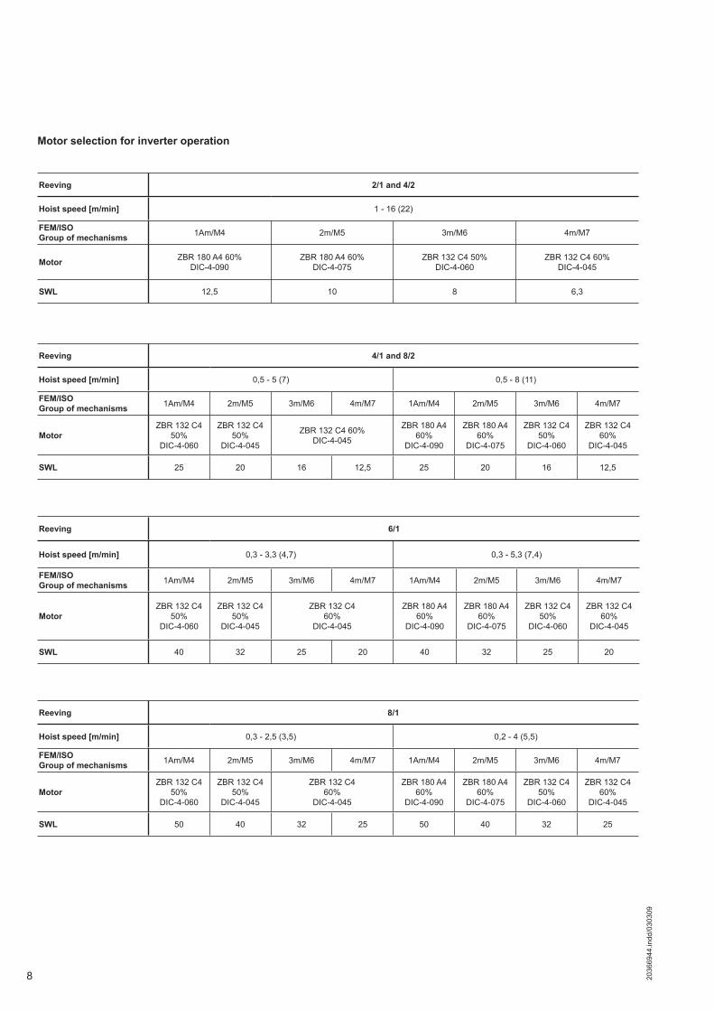
Motor selection for inverter operation
Reeving 2/1 and 4/2
Hoist speed [m/min] 1 - 16 (22)
FEM/ISO Group of mechanisms 1Am/M4 2m/M5 3m/M6 4m/M7
Motor ZBR 180 A4 60%DIC-4-090
ZBR 180 A4 60%DIC-4-075
ZBR 132 C4 50%DIC-4-060
ZBR 132 C4 60%DIC-4-045
SWL 12,5 10 8 6,3
Reeving 4/1 and 8/2
Hoist speed [m/min] 0,5 - 5 (7) 0,5 - 8 (11)
FEM/ISO Group of mechanisms 1Am/M4 2m/M5 3m/M6 4m/M7 1Am/M4 2m/M5 3m/M6 4m/M7
MotorZBR 132 C4
50%DIC-4-060
ZBR 132 C4 50%
DIC-4-045
ZBR 132 C4 60%DIC-4-045
ZBR 180 A460%
DIC-4-090
ZBR 180 A460%
DIC-4-075
ZBR 132 C450%
DIC-4-060
ZBR 132 C460%
DIC-4-045
SWL 25 20 16 12,5 25 20 16 12,5
Reeving 6/1
Hoist speed [m/min] 0,3 - 3,3 (4,7) 0,3 - 5,3 (7,4)
FEM/ISO Group of mechanisms 1Am/M4 2m/M5 3m/M6 4m/M7 1Am/M4 2m/M5 3m/M6 4m/M7
MotorZBR 132 C4
50%DIC-4-060
ZBR 132 C450%
DIC-4-045
ZBR 132 C460%
DIC-4-045
ZBR 180 A460%
DIC-4-090
ZBR 180 A460%
DIC-4-075
ZBR 132 C450%
DIC-4-060
ZBR 132 C460%
DIC-4-045
SWL 40 32 25 20 40 32 25 20
Reeving 8/1
Hoist speed [m/min] 0,3 - 2,5 (3,5) 0,2 - 4 (5,5)
FEM/ISO Group of mechanisms 1Am/M4 2m/M5 3m/M6 4m/M7 1Am/M4 2m/M5 3m/M6 4m/M7
MotorZBR 132 C4
50%DIC-4-060
ZBR 132 C450%
DIC-4-045
ZBR 132 C460%
DIC-4-045
ZBR 180 A460%
DIC-4-090
ZBR 180 A460%
DIC-4-075
ZBR 132 C450%
DIC-4-060
ZBR 132 C460%
DIC-4-045
SWL 50 40 32 25 50 40 32 25
92036
6944
.indd
/030
309
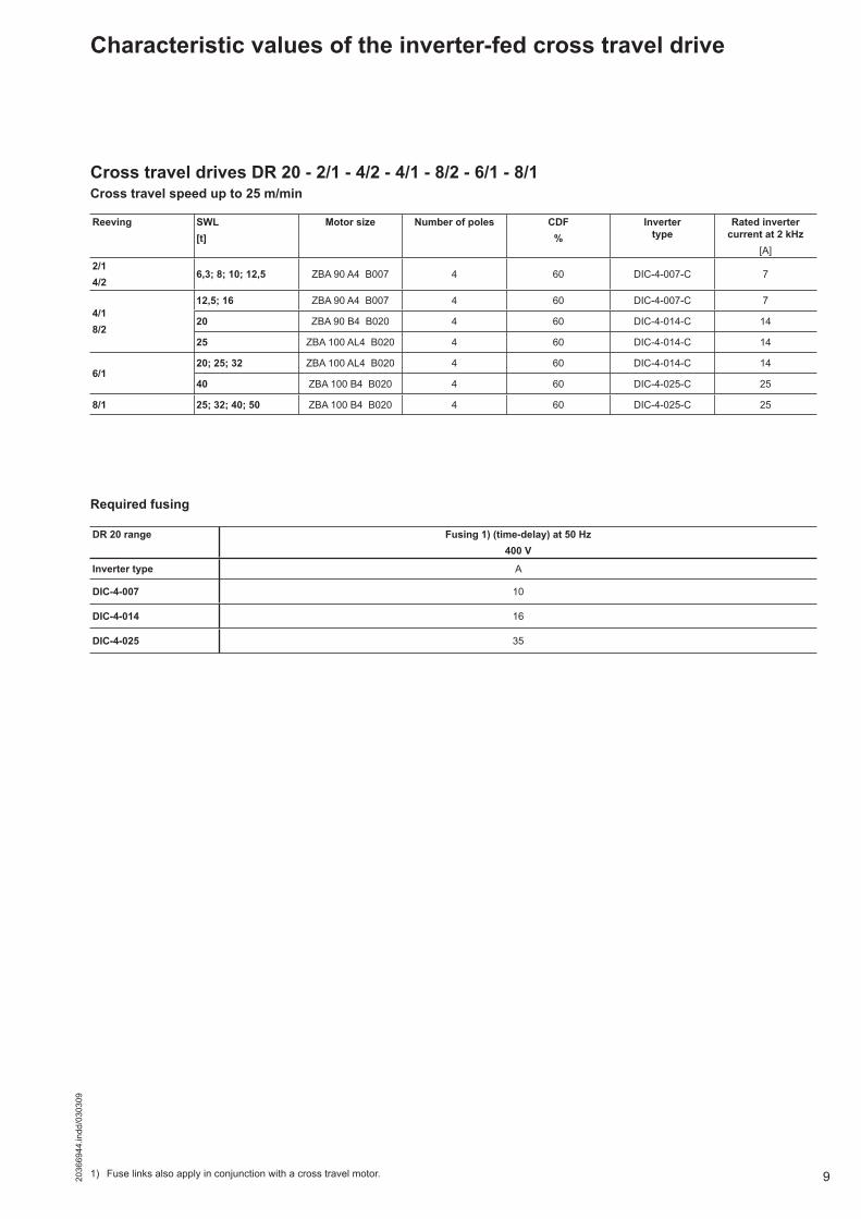
Characteristic values of the inverter-fed cross travel drive
Reeving SWL [t]
Motor size Number of poles CDF%
Inverter type
Rated inverter current at 2 kHz
[A]2/14/2
6,3; 8; 10; 12,5 ZBA 90 A4 B007 4 60 DIC-4-007-C 7
4/18/2
12,5; 16 ZBA 90 A4 B007 4 60 DIC-4-007-C 7
20 ZBA 90 B4 B020 4 60 DIC-4-014-C 14
25 ZBA 100 AL4 B020 4 60 DIC-4-014-C 14
6/120; 25; 32 ZBA 100 AL4 B020 4 60 DIC-4-014-C 14
40 ZBA 100 B4 B020 4 60 DIC-4-025-C 25
8/1 25; 32; 40; 50 ZBA 100 B4 B020 4 60 DIC-4-025-C 25
Cross travel drives DR 20 - 2/1 - 4/2 - 4/1 - 8/2 - 6/1 - 8/1Cross travel speed up to 25 m/min
DR 20 range Fusing 1) (time-delay) at 50 Hz 400 V
Inverter type A
DIC-4-007 10
DIC-4-014 16
DIC-4-025 35
Required fusing
1) Fuse links also apply in conjunction with a cross travel motor.
10 2036
6944
.indd
/030
309
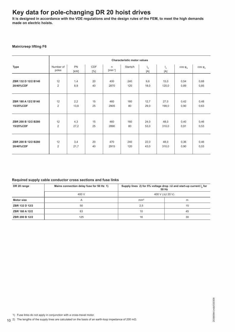
Key data for pole-changing DR 20 hoist drivesIt is designed in accordance with the VDE regulations and the design rules of the FEM, to meet the high demands made on electric hoists.
Main/creep lifting F6
Characteristic motor values
Type Number of poles
PN[kW]
CDF[%]
n[min-1]
Starts/h IN
[A]IA
[A]cos φN cos φA
ZBR 132 D 12/2 B14020/40%CDF
122
1,48,9
2040
4002870
240120
9,618,0
15,0120,0
0,540,89
0,680,85
ZBR 180 A 12/2 B14015/25%CDF
122
2,213,8
1525
4602905
16080
12,729,0
27,0199,0
0,420,90
0,480,63
ZBR 200 B 12/2 B28015/25%CDF
122
4,327,2
1525
4602890
16080
24,053,0
48,0310,0
0,400,91
0,460,53
ZBR 200 B 12/2 B28020/40%CDF
122
3,421,7
2040
4702915
240120
22,043,0
48,0310,0
0,360,90
0,460,53
1) Fuse links do not apply in conjunction with a cross-travel motor.2) The lengths of the supply lines are calculated on the basis of an earth-loop impedance of 200 mΩ.
Required supply cable conductor cross sections and fuse linksDR 20 range Mains connection delay fuse for 50 Hz 1) Supply lines 2) for 5% voltage drop ∆U and start-up current IA for
50 Hz
400 V 400 V (∆U 20 V)
Motor size A mm² m
ZBR 132 D 12/2 50 2,5 15
ZBR 180 A 12/2 63 10 45
ZBR 200 B 12/2 125 16 30
112036
6944
.indd
/030
309
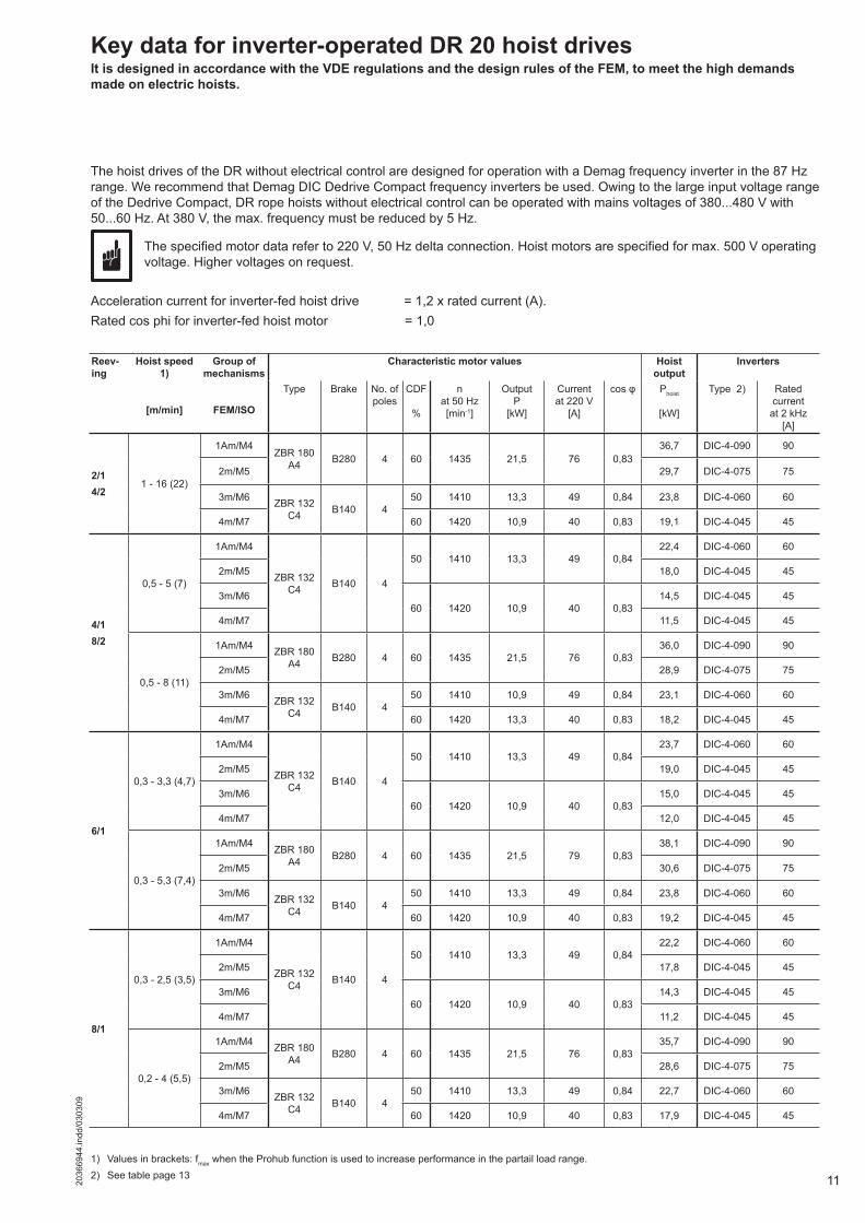
Acceleration current for inverter-fed hoist drive = 1,2 x rated current (A).Rated cos phi for inverter-fed hoist motor = 1,0
1) Values in brackets: fmax when the Prohub function is used to increase performance in the partail load range.2) See table page 13
Key data for inverter-operated DR 20 hoist drivesIt is designed in accordance with the VDE regulations and the design rules of the FEM, to meet the high demands made on electric hoists.
The hoist drives of the DR without electrical control are designed for operation with a Demag frequency inverter in the 87 Hz range. We recommend that Demag DIC Dedrive Compact frequency inverters be used. Owing to the large input voltage range of the Dedrive Compact, DR rope hoists without electrical control can be operated with mains voltages of 380...480 V with 50...60 Hz. At 380 V, the max. frequency must be reduced by 5 Hz.
The specified motor data refer to 220 V, 50 Hz delta connection. Hoist motors are specified for max. 500 V operating voltage. Higher voltages on request.
Reev-ing
Hoist speed 1)
[m/min]
Group of mechanisms
FEM/ISO
Characteristic motor values Hoist output
Inverters
Type Brake No. ofpoles
CDF
%
n at 50 Hz[min-1]
OutputP
[kW]
Currentat 220 V
[A]
cos φ Phoist
[kW]
Type 2) Rated currentat 2 kHz
[A]
2/14/2
1 - 16 (22)
1Am/M4ZBR 180
A4 B280 4 60 1435 21,5 76 0,8336,7 DIC-4-090 90
2m/M5 29,7 DIC-4-075 75
3m/M6 ZBR 132 C4 B140 4
50 1410 13,3 49 0,84 23,8 DIC-4-060 60
4m/M7 60 1420 10,9 40 0,83 19,1 DIC-4-045 45
4/18/2
0,5 - 5 (7)
1Am/M4
ZBR 132 C4 B140 4
50 1410 13,3 49 0,8422,4 DIC-4-060 60
2m/M5 18,0 DIC-4-045 45
3m/M660 1420 10,9 40 0,83
14,5 DIC-4-045 45
4m/M7 11,5 DIC-4-045 45
0,5 - 8 (11)
1Am/M4 ZBR 180 A4 B280 4 60 1435 21,5 76 0,83
36,0 DIC-4-090 90
2m/M5 28,9 DIC-4-075 75
3m/M6 ZBR 132 C4 B140 4
50 1410 10,9 49 0,84 23,1 DIC-4-060 60
4m/M7 60 1420 13,3 40 0,83 18,2 DIC-4-045 45
6/1
0,3 - 3,3 (4,7)
1Am/M4
ZBR 132 C4 B140 4
50 1410 13,3 49 0,8423,7 DIC-4-060 60
2m/M5 19,0 DIC-4-045 45
3m/M660 1420 10,9 40 0,83
15,0 DIC-4-045 45
4m/M7 12,0 DIC-4-045 45
0,3 - 5,3 (7,4)
1Am/M4 ZBR 180 A4 B280 4 60 1435 21,5 79 0,83
38,1 DIC-4-090 90
2m/M5 30,6 DIC-4-075 75
3m/M6 ZBR 132 C4 B140 4
50 1410 13,3 49 0,84 23,8 DIC-4-060 60
4m/M7 60 1420 10,9 40 0,83 19,2 DIC-4-045 45
8/1
0,3 - 2,5 (3,5)
1Am/M4
ZBR 132 C4 B140 4
50 1410 13,3 49 0,8422,2 DIC-4-060 60
2m/M5 17,8 DIC-4-045 45
3m/M660 1420 10,9 40 0,83
14,3 DIC-4-045 45
4m/M7 11,2 DIC-4-045 45
0,2 - 4 (5,5)
1Am/M4 ZBR 180 A4 B280 4 60 1435 21,5 76 0,83
35,7 DIC-4-090 90
2m/M5 28,6 DIC-4-075 75
3m/M6 ZBR 132 C4 B140 4
50 1410 13,3 49 0,84 22,7 DIC-4-060 60
4m/M7 60 1420 10,9 40 0,83 17,9 DIC-4-045 45
12 2036
6944
.indd
/030
309
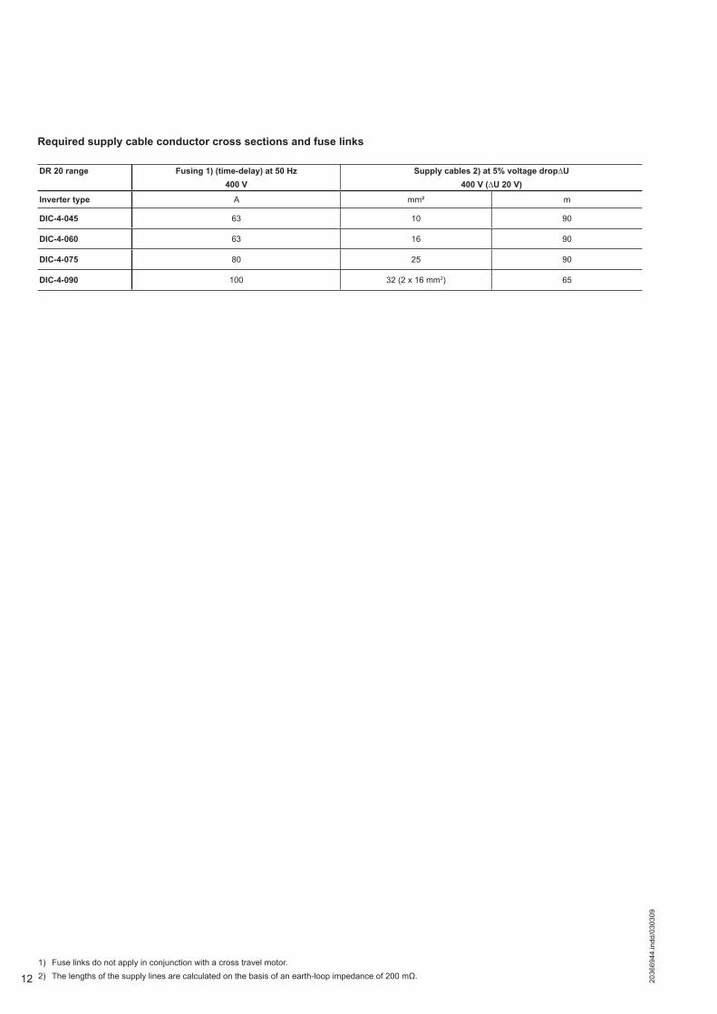
1) Fuse links do not apply in conjunction with a cross travel motor.2) The lengths of the supply lines are calculated on the basis of an earth-loop impedance of 200 mΩ.
DR 20 range Fusing 1) (time-delay) at 50 Hz 400 V
Supply cables 2) at 5% voltage drop∆U 400 V (∆U 20 V)
Inverter type A mm² m
DIC-4-045 63 10 90
DIC-4-060 63 16 90
DIC-4-075 80 25 90
DIC-4-090 100 32 (2 x 16 mm2) 65
Required supply cable conductor cross sections and fuse links
132036
6944
.indd
/030
309
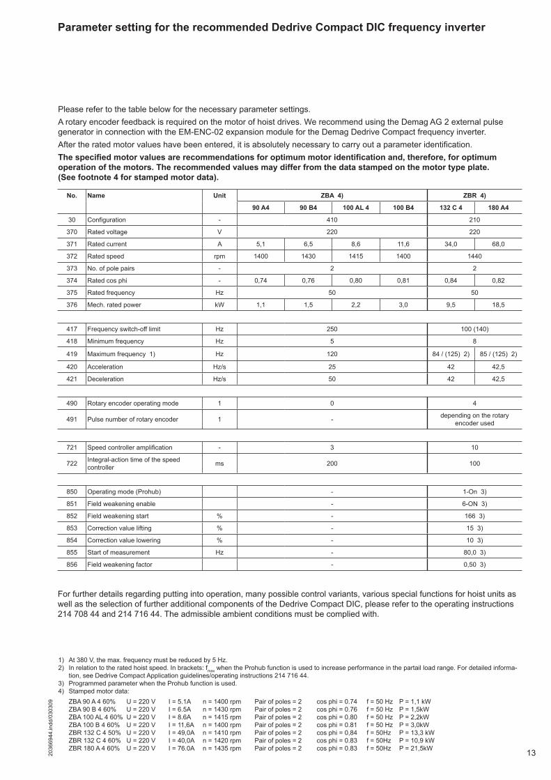
Please refer to the table below for the necessary parameter settings. A rotary encoder feedback is required on the motor of hoist drives. We recommend using the Demag AG 2 external pulse generator in connection with the EM-ENC-02 expansion module for the Demag Dedrive Compact frequency inverter.After the rated motor values have been entered, it is absolutely necessary to carry out a parameter identification.The specified motor values are recommendations for optimum motor identification and, therefore, for optimum operation of the motors. The recommended values may differ from the data stamped on the motor type plate. (See footnote 4 for stamped motor data).
Parameter setting for the recommended Dedrive Compact DIC frequency inverter
For further details regarding putting into operation, many possible control variants, various special functions for hoist units as well as the selection of further additional components of the Dedrive Compact DIC, please refer to the operating instructions 214 708 44 and 214 716 44. The admissible ambient conditions must be complied with.
No. Name Unit ZBA 4) ZBR 4)
90 A4 90 B4 100 AL 4 100 B4 132 C 4 180 A4
30 Configuration - 410 210
370 Rated voltage V 220 220
371 Rated current A 5,1 6,5 8,6 11,6 34,0 68,0
372 Rated speed rpm 1400 1430 1415 1400 1440
373 No. of pole pairs - 2 2
374 Rated cos phi - 0,74 0,76 0,80 0,81 0,84 0,82
375 Rated frequency Hz 50 50
376 Mech. rated power kW 1,1 1,5 2,2 3,0 9,5 18,5
417 Frequency switch-off limit Hz 250 100 (140)
418 Minimum frequency Hz 5 8
419 Maximum frequency 1) Hz 120 84 / (125) 2) 85 / (125) 2)
420 Acceleration Hz/s 25 42 42,5
421 Deceleration Hz/s 50 42 42,5
490 Rotary encoder operating mode 1 0 4
491 Pulse number of rotary encoder 1 - depending on the rotary encoder used
721 Speed controller amplification - 3 10
722 Integral-action time of the speed controller ms 200 100
850 Operating mode (Prohub) - 1-On 3)
851 Field weakening enable - 6-ON 3)
852 Field weakening start % - 166 3)
853 Correction value lifting % - 15 3)
854 Correction value lowering % - 10 3)
855 Start of measurement Hz - 80,0 3)
856 Field weakening factor - 0,50 3)
1) At 380 V, the max. frequency must be reduced by 5 Hz.2) In relation to the rated hoist speed. In brackets: fmax when the Prohub function is used to increase performance in the partail load range. For detailed informa-
tion, see Dedrive Compact Application guidelines/operating instructions 214 716 44.3) Programmed parameter when the Prohub function is used.4) Stamped motor data: ZBA 90 A 4 60% U = 220 V I = 5.1A n = 1400 rpm Pair of poles = 2 cos phi = 0.74 f = 50 Hz P = 1,1 kW ZBA 90 B 4 60% U = 220 V I = 6.5A n = 1430 rpm Pair of poles = 2 cos phi = 0.76 f = 50 Hz P = 1,5kW ZBA 100 AL 4 60% U = 220 V I = 8.6A n = 1415 rpm Pair of poles = 2 cos phi = 0.80 f = 50 Hz P = 2,2kW ZBA 100 B 4 60% U = 220 V I = 11,6A n = 1400 rpm Pair of poles = 2 cos phi = 0.81 f = 50 Hz P = 3,0kW ZBR 132 C 4 50% U = 220 V I = 49,0A n = 1410 rpm Pair of poles = 2 cos phi = 0,84 f = 50Hz P = 13,3 kW ZBR 132 C 4 60% U = 220 V I = 40,0A n = 1420 rpm Pair of poles = 2 cos phi = 0.83 f = 50Hz P = 10,9 kW ZBR 180 A 4 60% U = 220 V I = 76.0A n = 1435 rpm Pair of poles = 2 cos phi = 0.83 f = 50Hz P = 21,5kW
14 2036
6944
.indd
/030
309
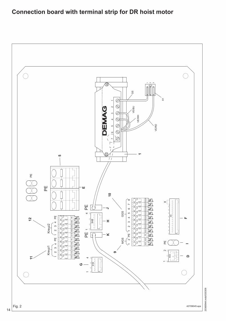
Connection board with terminal strip for DR hoist motor
42709045.epsFig. 2
PE
PE
1
87
65
43
21
PE
21M
GS
GG
S
SG
SS
GS
PE
SG
G1
SG
G8
SG
G7
SG
G6
SG
G5
SG
G4
SG
G3
SG
G2
X16
X48
X53
PE
X5
41
4
Kre
uz1
Kre
uz2
43
21
PE
32
1
X16
1X
484
X48
3X
482
X41
8P
EX
163
X16
2
PE
PE
4 X16
4
PE
81
2
PE
76
54
32
1
DE
MA
GD
EM
AG
X1
GS
VE
/BU
VE
/WH
VE
/RD
31 2
1
JH
K10
9
G
1112
5
FI
D
E

152036
6944
.indd
/030
309
1 Top-hat rail5 Protective earth conductor PE9 MGS electro-mechanical overload protection10 SGG geared limit switch11 General cross-travel limit switch12 Fast-to-slow cross-travel limit switch (v2 → v1)
D X53 terminal (MGS)E Protective earth conductor PEF X5 terminal (SGG)G X16 terminal (final lim. sw.)H X48 terminal (fast-to-slow lim. sw.)I Protective earth conductor PEJ Protective earth conductor PEK Protective earth conductor PE
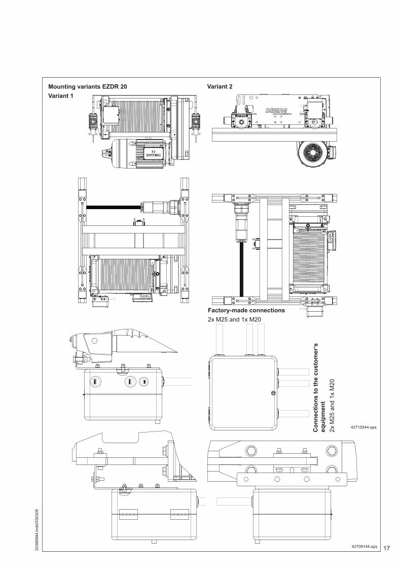
Connections to the customer‘s equipment
Factory-made connections
All terminals can be connected with up to 4 mm² copper cross-section, ex-cept for the PE terminals which can be connected with up to 16 mm² copper cross-section.
Important.GS modules must always be provided with a separate power supply when used with a pole-changing motor.
16 2036
6944
.indd
/030
309
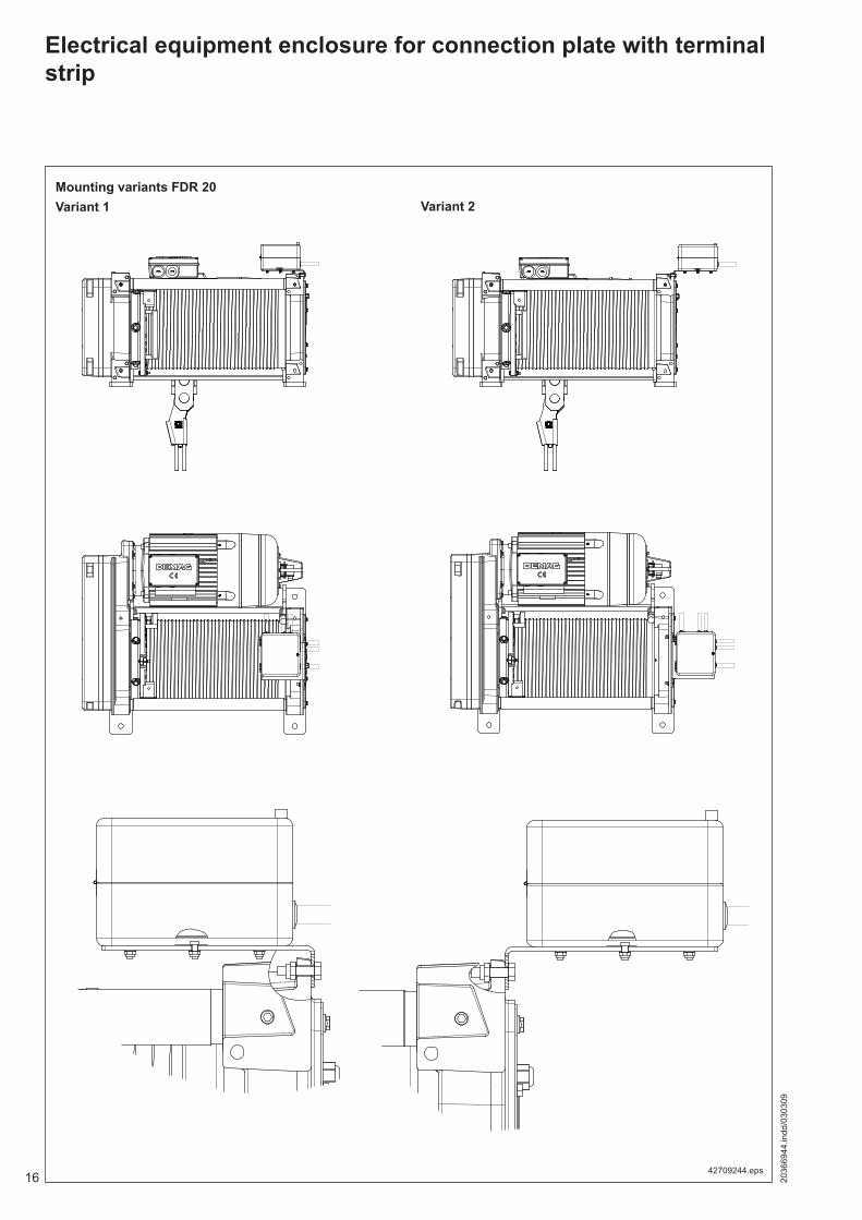
Electrical equipment enclosure for connection plate with terminal strip
42709244.eps
Mounting variants FDR 20Variant 1 Variant 2
172036
6944
.indd
/030
309
42709144.eps
Mounting variants EZDR 20Variant 1
Variant 2
Factory-made connections 2x M25 and 1x M20
Con
nect
ions
to th
e cu
stom
er‘s
eq
uipm
ent
2x M
25 a
nd 1
x M
20
42715544.eps
18 2036
6944
.indd
/030
309
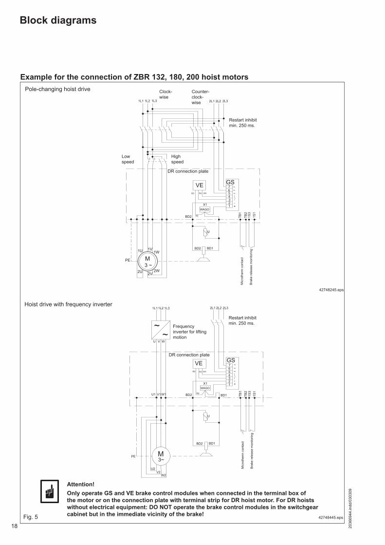
Block diagrams
Example for the connection of ZBR 132, 180, 200 hoist motors
PE M3~
2L1 2L31L11L2 1L3
~~
2L2
U V W
1234567
+-
~~~
RD WHBU
U
X1
RD
TB1
TB2
1S3
1S1
U1 V1W1
U2V2
W2
BD2 BD1
BD2 BD1
VE GS
WAGO
Hoist drive with frequency inverter
Pole-changing hoist drive
42748445.eps
Frequency inverter for lifting motion
Fig. 5
Restart inhibit min. 250 ms.
U
PE
1U 1V1W
3 ~M
2U 2V2W
1L2 1L31L1 2L2 2L32L1
TB2
1S3
TB1
12
1S1
43
5
7~6
-
~
+X1
~VEBU
GS
RD
BD1
WH
BD2 RD
BD2
WAGO
42748245.eps
Bra
ke re
leas
e m
onito
ring
Mic
roth
erm
con
tact
Lowspeed
Highspeed
Counter-clock-wise
Clock-wise
Restart inhibit min. 250 ms.
Bra
ke re
leas
e m
onito
ring
Mic
roth
erm
con
tact
Attention!Only operate GS and VE brake control modules when connected in the terminal box of the motor or on the connection plate with terminal strip for DR hoist motor. For DR hoists without electrical equipment: DO NOT operate the brake control modules in the switchgear cabinet but in the immediate vicinity of the brake!
DR connection plate
DR connection plate

192036
6944
.indd
/030
309
U V W
U1 V1 W1
TB1
TB2
BD2 BD1
BD2 BD1
PE
X1
VE
U
GE
M3~
7654321
~~
-+
~~
1L11L2 1L3 2L12L2 2L3
BURD WH
RD
WAGO
Frequency-controlled cross-travel drive
Example for the connection of a cross-travel motor
Fig. 6
AG external pulse generator See operating instructions “Motors, Z motor range”, ident no. 214 372 44
See operating instructions “Motors, Z motor range”, ident no. 214 228 44Note: It must be ensured that the brake release contact is evaluated in
the external electrical eqipment!
See operating instructions “Motors, Z motor range”, ident no. 214 228 44
Mic
roth
erm
co
ntac
t
42355845.eps
Temperature sensor for hoist and cross-travel motor
Brake release contact
20 2036
6944
.indd
/030
309
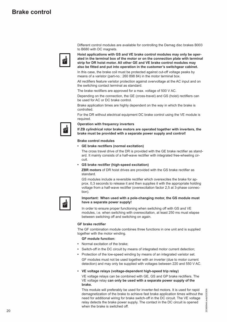
Brake control
Different control modules are available for controlling the Demag disc brakes B003 to B680 with DC magnets.Hoist applications with GS and VE brake control modules may only be oper-ated in the terminal box of the motor or on the connection plate with terminal strip for DR hoist motor. All other GE and VE brake control modules may also be fitted and put into operation in the customer’s switchgear cabinet.In this case, the brake coil must be protected against cut-off voltage peaks by means of a varistor (part-no.: 260 898 84) in the motor terminal box.All rectifiers feature varistor protection against overvoltage at the AC input and on the switching contact terminal as standard.The brake rectifiers are approved for a max. voltage of 500 V AC. Depending on the connection, the GE (cross-travel) and GS (hoist) rectifiers can be used for AC or DC brake control.Brake application times are highly dependent on the way in which the brake is controlled.For the DR without electrical equipment DC brake control using the VE module is required.Operation with frequency invertersIf ZB cylindrical rotor brake motors are operated together with inverters, the brake must be provided with a separate power supply and control!
Brake control modules• GE brake rectifiers (normal excitation) The cross travel drive of the DR is provided with the GE brake rectifier as stand-
ard. It mainly consists of a half-wave rectifier with integrated free-wheeling cir-cuit.
• GS brake rectifier (high-speed excitation) ZBR motors of DR hoist drives are provided with the GS brake rectifier as
standard. GS modules include a reversible rectifier which overexcites the brake for ap-
prox. 0,3 seconds to release it and then supplies it with the appropriate holding voltage from a half-wave rectifier (overexcitation factor 2,5 at 3-phase connec-tion).
Important: When used with a pole-changing motor, the GS module must have a separate power supply!
In order to ensure proper functioning when switching off with GS and VE modules, i.e. when switching with overexcitation, at least 250 ms must elapse between switching off and switching on again.
GF brake rectifierThe GF combination module combines three functions in one unit and is supplied together with the motor winding. GF module function:• Normal excitation of the brake;• Switch-off in the DC circuit by means of integrated motor current detection;• Protection of the low-speed winding by means of an integrated varistor set. GF modules must not be used together with an inverter (due to motor current
detection) and may only be supplied with voltages between 220 and 550 V AC.
• VE voltage relays (voltage-dependent high-speed trip relay) VE voltage relays can be combined with GE, GS and GP brake rectifiers. The
VE voltage relay can only be used with a separate power supply of the brake.
This module will preferably be used for inverter-fed motors. It is used for rapid demagnetization of the brake to achieve fast brake application times without the need for additional wiring for brake switch-off in the DC circuit. The VE voltage relay detects the brake power supply. The contact in the DC circuit is opened when the brake is switched off.
212036
6944
.indd
/030
309
1
2
4
3
5 5
6 6
7 7
8 8
3 3
4 4
1 1
2 2
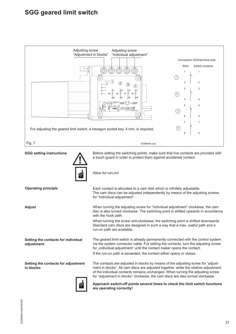
SGG geared limit switch
42589444.eps
Connection SGG/terminal strip
SGG Switch contacts
Fig. 7
Setting the contacts for individual adjustment:
Setting the contacts for adjustment in blocks:
Operating principle
Adjust
SGG setting instructions Before setting the switching points, make sure that live contacts are provided with a touch guard in order to protect them against accidental contact.
Allow for run-on!
Each contact is allocated to a cam disk which is infinitely adjustable. The cam discs can be adjusted independently by means of the adjusting screws for “individual adjustment”.
When turning the adjusting screw for “individual adjustment” clockwise, the cam disc is also turned clockwise. The switching point is shifted upwards in accordance with the hook path.When turning the screw anti-clockwise, the switching point is shifted downwards.Standard cam discs are designed in such a way that a max. useful path and a run-on path are available.
The geared limit switch is already permanently connected with the control system via the system connector cable. For setting the contacts, turn the adjusting screw for „individual adjustment“ until the contact maker opens the contact.If the run-on path is exceeded, the contact either opens or closes.
The contacts are adjusted in blocks by means of the adjusting screw for “adjust-ment in blocks”. All cam discs are adjusted together, while the relative adjustment of the individual contacts remains unchanged. When turning the adjusting screw for “adjustment in blocks” clockwise, the cam discs are also turned clockwise.
Approach switch-off points several times to check the limit switch functions are operating correctly!
Adjusting screw “Individual adjustment”
Adjusting screw“Adjustment in blocks”
For adjusting the geared limit switch, a hexagon socket key, 4 mm, is required.
22 2036
6944
.indd
/030
309
Reduction ratio:
Switching contacts:
Contact type:
Cam disc:
Switching point repeat accuracy:
Electrical connection:
Technical features:Compliance with standards
Ambient temperatureType of enclosureInsulation classApprovals
Technical features of the switching elements:Positive opening depending on rated operating voltage Ui
Continuous thermal current Ith
Utilisation category acc. to VDE 0660:
Mechanical service life in switching cyclesTerminal identificationApprovalsCurrent load for plug-in connection
External dimensions:Length up to pinion coverHousing dimensionsTotal height
i = 205 with adjustment of all cam discs in blocks designed for at least >1x10⁶ switching operations
4
Changeover contact, snap-action contact, positively opening NC contact, contact material: silver/silver
with 15° contact cams
approx. +/-15 mm on the hook, at worst case with 2/1 reeving and 12 m hook path. In this case 47 rotations of the drive shaft with i = 205 result in an adjusting angle on the camshaft of 79,71°.
Terminal strip direct plug-in on the PCB.
EN 60204-1 IEC 947-5-1 EN 60947-T5-1EN 60529 EN50013 IEC 536Continuous operation -40 °C to +80 °CIP 54II classCE and CSA
VDE 0660 part 200 v. 7/92250 VAC and 24/80 VDC6 AAC-15, 230 VAC/1,5 A
DC-13, 60 VDC/0,5 A10 x 106 switching operationsAcc. to EN 50013CE-UL/CSA6 A / 85 °C 250 VAC
approx. 165 mmapprox. 91 x 72 mmapprox. 95 mm
Technical data

232036
6944
.indd
/030
309
Load detector
MGS electro-mechanicaloverload cutout
42715644.eps
2-pole socket connector
Fig. 8
Depending on the type, the MGS cutout is set to the DR rated load and already fitted in the DR hoist unit. In order to avoid osciallations of the system due to switching off and on again, the MGS contact must additionally be evaluated. For the standard application we recommend using the MKA-2 contact evaluator. This device filters signals so that a premature release of lifting and the associated oscillations are prevented. This device is available for four voltage ranges and is supplied depending on the order. In combination with MGS, only the MGS overload cut-out function can be used.
MGS Load linkInput voltage: 24 V, 9600 HzOutput signal: Load link NC contact -X53V switching capacity: 10 mA / 24 V DCAmbient temperature: -20° C to +70° CType of enclosure: IP 67Mounting position: any
EMC cable gland M12x1,5 Reducing adaptor M20x1,5/M12x1,5
Reeving FEM/ISO Force on the MGS [kg]
Part no.:
2/1; 4/1; 6/1; 8/1
1Am/M4 6250 730 582 45
2m/M5 5000 730 583 45
3m/M6 4000 730 584 45
4m/M7 3125 730 585 45
4/2; 8/2
1Am/M4 3125 730 586 45
2m/M5 2500 730 587 45
3m/M6 2000 730 588 45
4m/M7 1575 730 589 45
approx. 10 mm screening braid laid bare
24 2036
6944
.indd
/030
309
41873344.eps
1 2 3 4 A2
A1 13 14 23 24
Dematik fiO.K CLK
46953144
gn br/ws ge
MKA-2
MGS
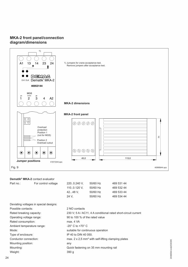
MKA-2 front panel
45,0 113,071
40995644.eps
Jumper positions
1) Jumpers for crane acceptance test.Remove jumpers after acceptance test.
1)
MKA-2 dimensions
MKA-2 front panel/connection diagram/dimensions
Position 2Overload cutout
Overload protectionPosition 1 (not for MGS)
Fig. 9
Dematik® MKA-2 contact evaluatorPart no.: For control voltage 220..0.240 V, 50/60 Hz 469 531 44 110..0.120 V, 50/60 Hz 469 532 44 42...48 V, 50/60 Hz 469 533 44 24 V, 50/60 Hz 469 534 44
Deviating voltages in special designs:Possible contacts: 2 NO contactsRated breaking capacity: 230 V; 5 A / AC11, 4 A conditional rated short-circuit currentOperating voltage range: 90 to 100 % of the rated value Rated consumption: max. 4 VAAmbient temperature range: -20° C to +70° CMode: suitable for continuous operationType of enclosure: IP 40 to DIN 40 050.Conductor connection: max. 2 x 2,5 mm² with self-lifting clamping platesMounting position: anyMounting: Quick fastening on 35 mm mounting railWeight: 390 g
252036
6944
.indd
/030
309
L1,L2,L3 PE
F2
K3 K4
M2
M3
L4
S1 S2
S2 S1
24
23U1
S3 S3
K4 K3
K3 K4
L5
A1
U1
A2 2 3
Dematik MKA-2
11 12
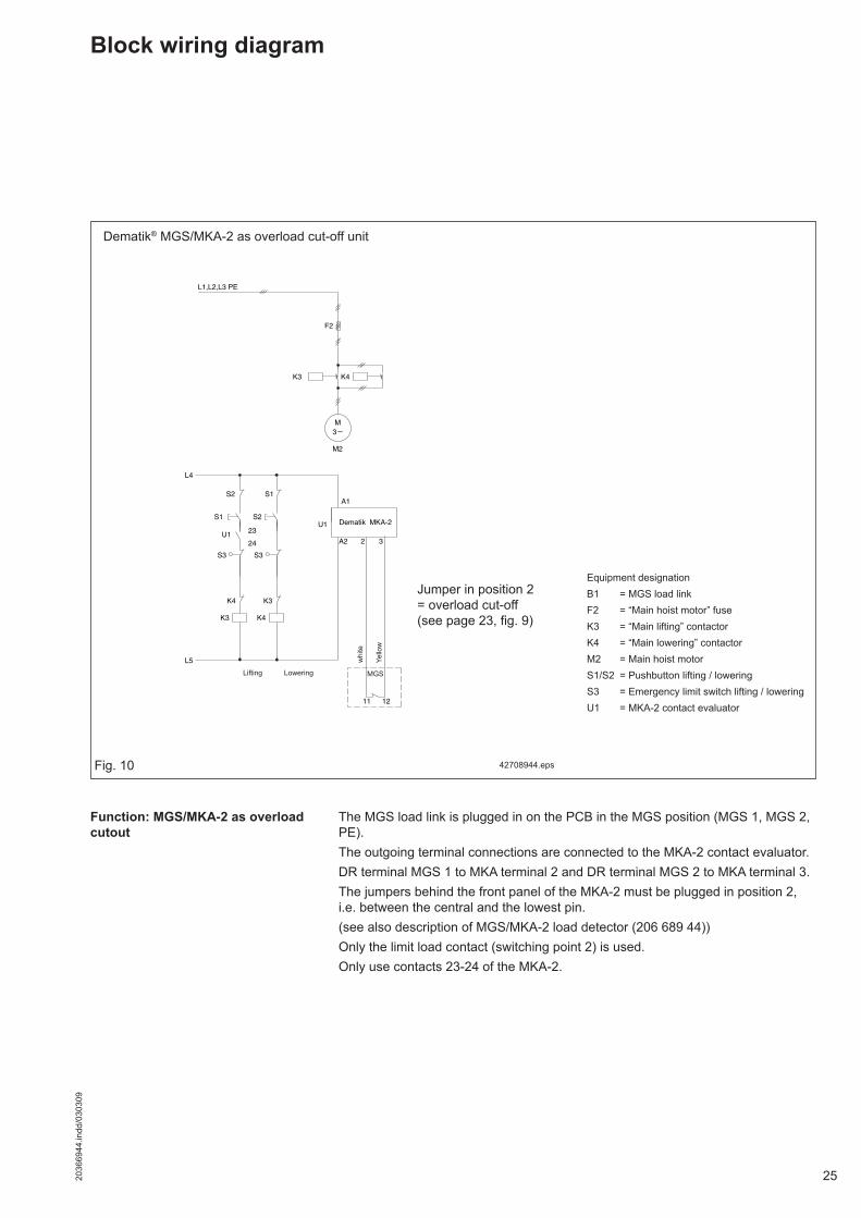
Block wiring diagram
Dematik® MGS/MKA-2 as overload cut-off unit
Equipment designationB1 = MGS load linkF2 = “Main hoist motor” fuseK3 = “Main lifting” contactor K4 = “Main lowering” contactorM2 = Main hoist motorS1/S2 = Pushbutton lifting / loweringS3 = Emergency limit switch lifting / loweringU1 = MKA-2 contact evaluator
Fig. 10
whi
te
Yello
w
Lifting Lowering
Jumper in position 2= overload cut-off(see page 23, fig. 9)
42708944.eps
The MGS load link is plugged in on the PCB in the MGS position (MGS 1, MGS 2, PE). The outgoing terminal connections are connected to the MKA-2 contact evaluator. DR terminal MGS 1 to MKA terminal 2 and DR terminal MGS 2 to MKA terminal 3. The jumpers behind the front panel of the MKA-2 must be plugged in position 2, i.e. between the central and the lowest pin.(see also description of MGS/MKA-2 load detector (206 689 44)) Only the limit load contact (switching point 2) is used.Only use contacts 23-24 of the MKA-2.
Function: MGS/MKA-2 as overload cutout
MGS
26 2036
6944
.indd
/030
309
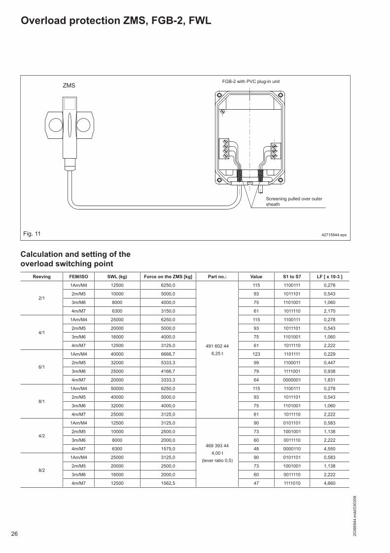
Overload protection ZMS, FGB-2, FWL
42715844.eps
Screening pulled over outer sheath
Calculation and setting of the overload switching point
ZMSFGB-2 with PVC plug-in unit
Fig. 11
Reeving FEM/ISO SWL (kg) Force on the ZMS [kg] Part no.: Value S1 to S7 LF [ x 10-3 ]
2/1
1Am/M4 12500 6250,0
491 602 446,25 t
115 1100111 0,278
2m/M5 10000 5000,0 93 1011101 0,543
3m/M6 8000 4000,0 75 1101001 1,060
4m/M7 6300 3150,0 61 1011110 2,170
4/1
1Am/M4 25000 6250,0 115 1100111 0,278
2m/M5 20000 5000,0 93 1011101 0,543
3m/M6 16000 4000,0 75 1101001 1,060
4m/M7 12500 3125,0 61 1011110 2,222
6/1
1Am/M4 40000 6666,7 123 1101111 0,229
2m/M5 32000 5333,3 99 1100011 0,447
3m/M6 25000 4166,7 79 1111001 0,938
4m/M7 20000 3333,3 64 0000001 1,831
8/1
1Am/M4 50000 6250,0 115 1100111 0,278
2m/M5 40000 5000,0 93 1011101 0,543
3m/M6 32000 4000,0 75 1101001 1,060
4m/M7 25000 3125,0 61 1011110 2,222
4/2
1Am/M4 12500 3125,0
469 393 444,00 t
(lever ratio 0,5)
90 0101101 0,583
2m/M5 10000 2500,0 73 1001001 1,138
3m/M6 8000 2000,0 60 0011110 2,222
4m/M7 6300 1575,0 48 0000110 4,550
8/2
1Am/M4 25000 3125,0 90 0101101 0,583
2m/M5 20000 2500,0 73 1001001 1,138
3m/M6 16000 2000,0 60 0011110 2,222
4m/M7 12500 1562,5 47 1111010 4,660
272036
6944
.indd
/030
309
FWL load spectrum recorder
The service life of hoist units decisively depends on the selection of the correct group of mechanisms, i.e. on the correct assessment of the operating time and load spectrum. However, during the long service life the operating conditions may change, which results either in a longer or shorter service life. Thus e.g. a change from one-shift operation to two-shift operation of a production crane doubles the operating time per day and as a result the drive mechanisms wear down faster.Since all hoist units are designed for specific periods of operation according to the rules of endurance strength, failures are to be expected after the calculated service life has elapsed.The FWL records all loads exerted on the hoist unit during operation and is power-failure and long-term safe. The load spectrum recorder displays the operating time.Thus a statement on the operating conditions and the calculated remaining dura-tion of service of the hoist unit can be made at any time.
The load spectrum recorder measures the lifted load and the hoist motor operating period.The load measured is compared to the rated SWL and a relative load is calculated. Since wear of the moving parts of the hoist unit increases disporportionately with increasing load, the value of the relative load is evaluated correspondingly. Based on this evaluation, operation of the hoist unit at half rated load only results in (1/2)3 = 1/8 of the load spectrum value reached with operation at rated load. At ¼ rated load the load spectrum value is (1/4)3 = 1/64 etc.The operating time of the hoist unit is measured as cyclic duration factor of the lifting and lowering motion. Since wear is expected to be proportional to the oper-ating time, the value measured in entered into the displayed load spectrum value proportional to the time. Thus double operating time at equal load corresponds to a double load spectum value.The load spectrum recorder continuously collects the measured load of the hoist unit for any loads and operating intervals. Thus the displayed load spectrum value corresponds to the total load exerted on the hoist unit up to now. In contrast to the elapsed operating time counter, the load spectrum recorder does not only display the pure operating time of the hoist unit, but it records the load on the hoist unit which has much more significance for wear and evaluates it depending on its influence.The counter in the load spectrum recorder is adjusted so that when the strain gauge carrier link is loaded with its rated SWL, the load spectrum value per second counts further +1.Thus the load spectrum recorder is an efficient means for monitoring hoists units.Since the displayed load spectrum value is recorded continuously, the owner may easily receive important data for the cost-efficient planning of maintenance and preventive repair work.On the basis of the recorded load spectrum values, the utilization of hoist units can be analysed, in order to plan extension and rationalization measures appropriately. In connection with the elapsed operating time counter, the load and operating time class acc. to FEM can be verified at any time.
Application
Mode of operation
28 2036
6944
.indd
/030
309
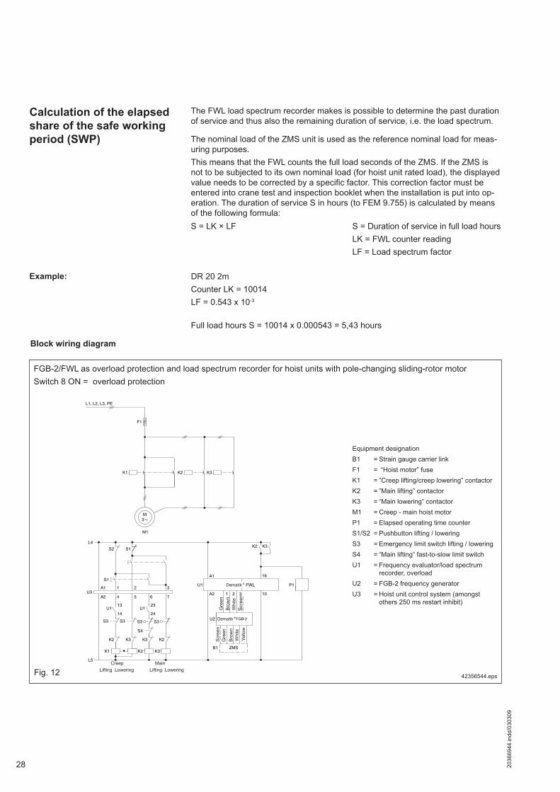
Calculation of the elapsed share of the safe working period (SWP)
The FWL load spectrum recorder makes is possible to determine the past duration of service and thus also the remaining duration of service, i.e. the load spectrum.
The nominal load of the ZMS unit is used as the reference nominal load for meas-uring purposes. This means that the FWL counts the full load seconds of the ZMS. If the ZMS is not to be subjected to its own nominal load (for hoist unit rated load), the displayed value needs to be corrected by a specific factor. This correction factor must be entered into crane test and inspection booklet when the installation is put into op-eration. The duration of service S in hours (to FEM 9.755) is calculated by means of the following formula:
S = Duration of service in full load hoursLK = FWL counter readingLF = Load spectrum factor
Example: DR 20 2mCounter LK = 10014LF = 0.543 x 10⁻³
S = LK × LF
Full load hours S = 10014 x 0.000543 = 5,43 hours
L1, L2, L3, PE
F1
K2
M3
M1
K3K1
K1
K2
U113
14
K2 K3
S3
K3
S3
K3
U123
24
S3
K2
S3
U3A1 1 2 3
A2 4 5 7
S2 S1
U2
ZMSB1
U1
A1
A2 2 31
FWL
16
10
P1
K2 K3L4
L5
S1
S4
FGB-2
6
Equipment designationB1 = Strain gauge carrier linkF1 = “Hoist motor” fuseK1 = “Creep lifting/creep lowering” contactorK2 = ”Main lifting” contactor K3 = “Main lowering” contactor M1 = Creep - main hoist motorP1 = Elapsed operating time counterS1/S2 = Pushbutton lifting / loweringS3 = Emergency limit switch lifting / loweringS4 = “Main lifting” fast-to-slow limit switchU1 = Frequency evaluator/load spectrum
recorder, overloadU2 = FGB-2 frequency generator U3 = Hoist unit control system (amongst
others 250 ms restart inhibit)
FGB-2/FWL as overload protection and load spectrum recorder for hoist units with pole-changing sliding-rotor motorSwitch 8 ON = overload protection
42356544.eps
Gre
en
Scr
een
Whi
teB
row
nG
reen
Scr
een
Bro
wn
Whi
teYe
llow
Creep MainLifting Lowering Lifting LoweringFig. 12
Block wiring diagram
292036
6944
.indd
/030
309
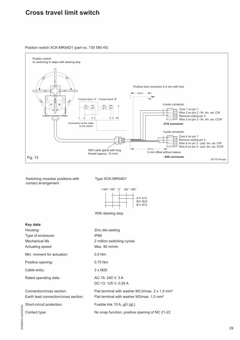
Cross travel limit switch
Position switch XCK-MR54D1 (part no. 730 590 45)
42715744.eps
Switching crossbar positions with contact arrangement
Type XCK-MR54D1
With slewing stop
Key data:Housing: Zinc die-castingType of enclosure: IP66Mechanical life 2 million switching cyclesActuating speed: Max. 90 m/min
Min. moment for actuation: 0.5 Nm
Positive opening: 0.75 Nm
Cable entry: 3 x M20
Rated operating data: AC-15: 240 V; 3 A DC-13: 125 V; 0,55 A
Connection/cross section: Flat terminal with washer M3,5/max. 2 x 1,5 mm²Earth lead connection/cross section: Flat terminal with washer M3/max. 1,5 mm²
Short-circuit protection: Fusible link 10 A, gG (gL)
Contact type: No snap function, positive opening of NC 21-22
4
4
Contact block “A”
Positive lock connector 6,3 mm with lock
4-pole connector
4-pole connector
-X16 connector
Core 1 on pin 1Wire 2 on pin 2 - fin. lim. sw. CWRemove coding pin 3Wire 3 on pin 3 - fin. lim. sw. CCW
-X48 connector
Position switch2x switching in steps with slewing stop
5 mm offset without sleeve
Contact block “B”
M20 cable gland with long thread (approx. 15 mm)
Connection of the cable to the switch:
+180° +90° 0° -180°-90°
A11 A12B21 B22B11 B12
Fig. 13
Core 4 on pin 1Remove coding pin 2Wire 5 on pin 2 - prel. lim. sw. CWWire 6 on pin 3 - prel. lim. sw. CCW
30 2036
6944
.indd
/030
309
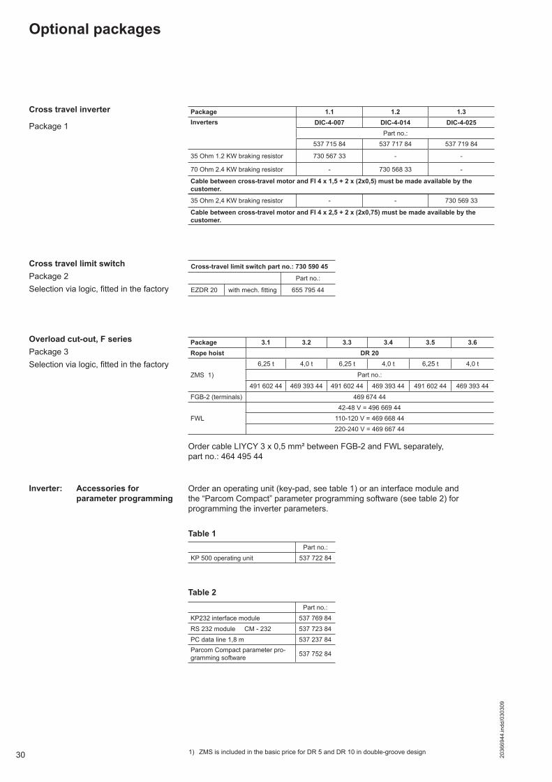
Optional packages
Package 1
Order cable LIYCY 3 x 0,5 mm² between FGB-2 and FWL separately, part no.: 464 495 44
Cross travel inverter
Cross travel limit switchPackage 2Selection via logic, fitted in the factory
Overload cut-out, F seriesPackage 3Selection via logic, fitted in the factory
Order an operating unit (key-pad, see table 1) or an interface module and the “Parcom Compact” parameter programming software (see table 2) for programming the inverter parameters.
Inverter: Accessories for parameter programming
Table 1
1) ZMS is included in the basic price for DR 5 and DR 10 in double-groove design
Package 1.1 1.2 1.3Inverters DIC-4-007 DIC-4-014 DIC-4-025
Part no.:537 715 84 537 717 84 537 719 84
35 Ohm 1.2 KW braking resistor 730 567 33 - -
70 Ohm 2.4 KW braking resistor - 730 568 33 -
Cable between cross-travel motor and FI 4 x 1,5 + 2 x (2x0,5) must be made available by the customer.
35 Ohm 2,4 KW braking resistor - - 730 569 33
Cable between cross-travel motor and FI 4 x 2,5 + 2 x (2x0,75) must be made available by the customer.
Cross-travel limit switch part no.: 730 590 45
Part no.:
EZDR 20 with mech. fi tting 655 795 44
Package 3.1 3.2 3.3 3.4 3.5 3.6Rope hoist DR 20
ZMS 1)
6,25 t 4,0 t 6,25 t 4,0 t 6,25 t 4,0 t
Part no.:
491 602 44 469 393 44 491 602 44 469 393 44 491 602 44 469 393 44
FGB-2 (terminals) 469 674 44
FWL42-48 V = 496 669 44
110-120 V = 469 668 44220-240 V = 469 667 44
Part no.:KP 500 operating unit 537 722 84
Part no.:KP232 interface module 537 769 84RS 232 module CM - 232 537 723 84PC data line 1,8 m 537 237 84Parcom Compact parameter pro-gramming software 537 752 84
Table 2

312036
6944
.indd
/030
309
Notes

Demag Cranes & Components GmbHP.O. Box 67, D-58286 WetterTelephone +49 (0) 2335 92-0 · Telefax +49 (0) 2335 927676www.demagcranes.com
Prin
ted
in G
erm
any
Reproduction in whole or in part only with prior consent of Demag Cranes & Components GmbH, D-58286 Wetter Subject to change. Not liable for errors or omissions.