Embed Size (px)
Citation preview
Before using this Stitcher Head, all operators must study this manual and follow the safety warnings and instructions. Keep these instructions with the Stitcher Head for future reference. If you have any questions, contact your local DeLuxe Stitcher Representative or Distributor.
DB75, DB75V & DB75VS
OPERATION AND MAINTENANCE MANUAL
DB75HD231/2.....Stitcher Head....23 WireDB75HD251/2....Stitcher Head.....25 Wire
DB75HD20241/2..Stitcher Head..20x24 WireDB75VHD231/2...Stitcher Head...23 Wire
DB75VHD251/2....Stitcher Head.....25 WireDB75VHD20241/2..Stitcher Head..20x24 Wire
DB75VSHD231/2...Stitcher Head...23 WireDB75VSHD251/2....Stitcher Head.....25 Wire
DB75VSHD20241/2..Stitcher Head..20x24 Wire
Head Serial Number : Date Purchased : Where Installed: (make/model of machine)
DELUXE STITCHERC O M P A N Y I N C .
®
solving your wire stitching needs for 125 years...

1
WARNING!
DB75/75V/75VS HeadsMachine operators and others in the work area should always wear
safety glasses to prevent serious eye injury fromfasteners and flying debris when loading, operating,
or unloading the stitcher machine.
Do not operate this stitcher head without all stitcher machine guards in place. Do not modify the guards in any way.Always disconnect the power supply before removing
any guards for servicing.
Never operate the machine with wire feeding throughthe head unless there is stock above the clinchers,
otherwise serious damage may result.
Always turn power off when making adjustments. Alwaysdisconnect the power cord before any disassembly work.
EYEWEAR
REQUIRED

2
THANK YOU FOR CHOOSING THEDB75, DB75V, OR DB75VS STITCHER HEAD
FOR YOUR BINDING NEEDS

Introduction ........................................................................................................4
Specifications .....................................................................................................5
Installation .......................................................................................................6 Pre-Inspection ................................................................................6 Inspection ......................................................................................6 Mounting ........................................................................................6 Assembly ..................................................................................... 6-8
Operation ........................................................................................................9 Wire Threading ........................................................................... 9-10 Wire Straightening ........................................................................11 Adjustments and Settings .......................................................... 12-14
Maintenance ......................................................................................................14 Lubrication ................................................................................. 14-15
Ordering Spare Parts .....................................................................................16
Troubleshooting ............................................................................................. 17-18
Appendices ......................................................................................................19 Exploded Drawings ..................................................................... 19-36 Notes .............................................................................................37 Part Number/Description Cross Reference Index...................... 38-39
Registration Card .............................................................................40
Wear/Replacement Parts ..............................................................................41
Warranty .......................................................................................................42
Table of Contents
3

The DeLuxe Stitcher Müller-Martini Replacement Heads, along with a complete line of fully interchangeable replacement parts are available for current Müller-Martini users. Anywhere the HK75, HK75V and HK75VS are utilized the DeLuxe Stitcher DB75HD, DB75VHD, & DB75VSHD can be used.
The DB75HD has a stitching capacity from 2 sheets up to 5mm (.197”) and will accommodate wire sizes from 20-28 gauge round as well as 21 x 25 and 20 x 24 flat. The perfect replacement head for Müller-Martini Stitchers 221, 235, 321, 335, Prima, Bravo and more, the DB75HD is completely interchangeable.
The DB75VHD & DB75VSHD have a stitching capacity from 2 sheets up to 6mm (.236) and will accommodate wire sizes from 20-28 gauge round as well as 21 x 25 and 20 x 24 flat. This replacement head for Müller-Martini Stitchers 301, Tempo, Optima, Supra and the like, is also completely interchangeable.
Each of these heads weighs 7 lbs (3.2 kgs.) independently. The packaged shipping weight including the Wire Guide Spring, Clincher Plate assembly and user manuals is 10 lbs. (4.5 kgs.).
Always use a high quality Galvanized Wire so the plating does not peel. Excessive peeling will cause clogging and the premature wear of many components. Use the following chart as a guide for wire gauge usage.
2 sheets - 1/8” (3mm) .......................... 25 gauge
1/8” (3mm) - 7/32” (6mm) .................. 23 or 24 gauge
For heavy paper ................................... 20 to 22 gauge round or 20x24 flat
NOTE: ALL PRODUCTS ARE MANUFACTURED BY DELUXE STITCHER.
Introduction
4

Weight: Shipping Weight . . . . . . . . . . . . . . . 10 lbs (4.5 kg) Box Dimensions . . . . . . . . . . . . . . . 21" x 10" x 7" (53 x 25 x 18 cm) Stitcher Head: DB75HD . . . . . . . . . . . . 7 lbs (3.2 kg) DB75VHD . . . . . . . . . . . 7 lbs (3.2 kg) DB75VSHD . . . . . . . . . . 7 lbs. (3.2 kg)Physical Dimensions Height . . . . . . . . . . . . . . . . . . . . 8.5” (22 cm) Width . . . . . . . . . . . . . . . . . . . . 3.5” (9 cm) Depth . . . . . . . . . . . . . . . . . . . . 4.25” (11 cm)Stitching Capacity DB75HD . . . . . . . . . . . . Two Sheets to 13/64” (5 mm)* DB75VHD . . . . . . . . . . . Two Sheets to 1/4” (6 mm)* DB75VSHD . . . . . . . . . . Two Sheets to 1/4" (6mm)*Wire Types . . . . . . . . . . . . . . . . . . . . 20 through 28 round or 21 x 25 and 20 x 24 flat* Actual stitching thickness capacity depends on the type of stock being stitched and the capacity of the saddle stitcher being used.
Specifications
5
Stitcher Head / Stitcher Machine CompatibilityStitcher Machine Compatible Stitcher Heads
JGV DB75HD DB75VHD DB45HD Loop not recommended. X
Fox, 221, 235 DB75HD DB75VHD DB45HD DB75VHD-LOOP X
331, 335 DB75HD DB75VHD DB45HD DB75VHD-LOOP X
Bravo/Prima(Built before 2004) DB75HD DB75VHD DB45HD DB75VHD-LOOP X
Bravo/Prima(Built 2004 or later) DB75LPHD DB75VLPHD DB45LPHD DB75VLPHD-LOOP X
Valore/Presto(All) DB75MPHD DB75VMPHD DB45MPHD X X
1509/Minuteman(Built before 2004) DB75MMHD DB75VMMHD DB45MMHD DB75VMMHD-LOOP X
1509/Minuteman(Built 2004 or later) DB75MMMPHD DB75VMMMPHD DB45MMMPHD DB75VMMMPHD-LOOP X
301/Optima/Tempo/Supra X X X X DB75VSHD

Attaching the Feed Release Handle (Figure 2)
From out of the box, secure the Feed Release Handle [070119] to the Stitcher Head by slipping the Handle over the Feed Release Cam Assembly [070118] and securing it with the provided screw, inserting it through the Spring. Make sure the Handle is angled toward the outside of the Head when you the screw is tightened.
Carefully inspect the condition of the shipping container before unpacking your replacement Head for Müller-Martini Stitchers. If the container is broken or damaged and there is evidence that the
stitcher head may be damaged, immediately notify the carrier who delivered the head and the DeLuxe Stitcher Graphic Arts Representative from whom the Head was purchased.
Installation
6
Pre-Inspection
As you carefully unpack the replacement head, check to make sure all components were delivered and are in good working order. Use Figure 1 in this manual for refer-ence to the following pieces:
• Replacement Head for Müller Martini Stitchers: DB75HD, DB75VHD or DB75VSHD
• Wire Guide Spring [070286]• Clincher Plate Assembly [077030 or
077030C]• Feed Release Handle [070119]• 2.5, 3, 4 and 5mm Hex Key Wrenches
[G20361, G20360, G20373 and G20362]• Stitch samples
Inspection (Figure 1)
Figure 1 - Inspection
070286
077030 (DB75) or 077030C (DB75V/VS)
070119
G20360(3 mm)
G20362(5 mm)
G20361(2.5 mm)
G20373(4 mm)
Mounting & Assembly (Figure 2-6)
Figure 2- Feed Release Handle
Screw
Spring
Handle

7
Wire Guide Spring070286
Feed Release Handle070119
Mounting Strap077006BB or
077027BBMounting
Screw072013
Lock WasherG20520
Bender Slide070162A or
070562A
Driver Slide070151A or
070551A
Feed Release
Cam070118
Washer071006 (2)
Screw072017 (2)
Figure 4 - Attaching the Wire Guide Spring
Bonnet Rail
Bonnet Key
Figure 3a - Mounting the Head
Figure 3b - Mounting Variation for DB75VS
Mounting the Head ( See Figure 3)
Attaching the Wire Guide Spring (Figure 4)

8
Figure 6 - AligningClincher Plate AssemblyClincher
Mounting Bar077016
Clincher Plate Assembly
Mounting Screws
072012 (2)
Clincher Slide 077014 or077029C
Figure 5 - Mounting Clincher Plate Assembly
Always disconnect the power before assemblingor making adjustments to your stitcher machine.
!CAUTION!
Clincher Front Plate
077018 Clincher Front Plate
077019Lock Washers
G20520 (2)
Mounting the Clincher Plate (Figure 5 & 6)
Clincher Points077015 (2)

Operation
Wire Threading (Figure 7-8)
9
Feed Release Handle070119
Wire Holder Retaining
Spring070183 or
070583
Wire Oiler Felts
G20293
Small Feed Gear
070112
Large Feed Gear
070510A
Retaining Spring Screw
072004
Figure 7 - Wire Threading
DISENGAGEGEARS
ENGAGEGEARS
Wire Guide Spring070286
Wire
Wire Nozzle070181

Before the Stitcher Machine is turned on, release the Wire Holder Assembly [070135A] (Not shown-See Fig. #) secured by the Wire Holder Retaining Spring [070183 or 070583] by loosening the Screw [072004] on the front of the Head. Thread the wire from the Spool under the studs on the Wire Guide Spring (070286), between the Wire Oiler Felts [G20293] on the Spring and into the Wire Nozzle [070181]. Turn the Feed Release Handle [070119)] clockwise so that the Small Feed Gear [070112] is disengaged from the Large Feed Gear [070510A].
Continue to push wire through the Replacement Head until the end of the wire passes the Small and Large Feed Gears, enters the Wire Tube [070544] and begins to come out the bottom of the Wire Tube. Then using a small screw driver, wedge the wire up until it enters the Fixed Wire Cutter [070600C]. Engage the Small and Large Feed Gears by turning the Adjustable Lever counter-clockwise.
Note: It will take two full cycles for the proper length staple to come out of the Head.
10
Fixed Cutter070600C
Wire Tube070544
Bottom View
Figure 8 - Wire Threading

11
Wire Straightening (Figure 9)
Once threaded, cycle the Stitcher Machine and watch the wire feeding out of the the Cutter Box [070197A or 070597A] to the right of the Moving Cutter [070145C]. The wire should be traveling in an approximate horizontal direction when exiting the Cutter Box.
Top-to-Bottom Adjustment If the Wire is feeding in an upward or downward direction, the Wire Straightener [070206A] will have to be adjusted. Loosen the Screw [G20589] securing the Wire Straightener to the Cutter Box. If the wire is feeding in an upward direction, slide the Wire Straightener down slightly. Conversely, if the wire is feeding in a downward direction, slide the Assembly up slightly. Make sure to tighten the Screw after every adjustment to see accurate results. Allow enough Wire to be fed through the Head so that an accurate assessment can be made. Make sure the ends of each cut piece of Wire is free of burrs, which would negatively affect the driving and clinching of the formed Wire.
Figure 9 - Wire Straightening
Make sure the Wire Holder Assembly has been removed before tripping the Machine
to avoid jams and the chipping of parts.
WARNING!
Moving Cutter
070145C
Wire Straightener
070206A
ScrewG20589
Bad
Good
Bad

Setting the Stitch’s Right Leg (& Setting It's Center) If after a few stitches, the length of the stitch’s right leg is too short or too long, you will need to make adjustments. Adjustments are always made to the right leg to compensate for the length of the left leg. First adjust the stitch’s right leg to match the left and then make adjustments for the overall length of the stitch or wire draw.
Power off the Stitcher Machine and release the Extension Spring [074002] from the Feed Gear Operating Lever Pin [043002] on the Replacement Head. Disengage the Small Feed Gear from the Large Feed Gear by turning the Feed Release Handle [070119]. Push the Feed Gear Operating Lever [077001] down which will move the pin on the Feed Gear Pinion [070111A] out of the way of the Feed Gear Stop [077026]. Loosen, but do not remove, the Screw [G20589] securing the Feed Gear Stop to the top of the Cutter Box Assembly. If the legs of the stitch are not even, do one othe following: If the right leg is too short, slide the Feed Gear Stop to the left slightly, to lengthen it.
If the right leg is too long, then adjust the Feed Gear Stop slightly to the right.
Tighten the screw and replace the Extension Spring.
Adjusting the Length of the Right Leg (Figure 10-12)
Figure 10 - Adjusting the Right Leg
ExtensionSpring074002
Feed Gear Operating
Lever043002
Feed Gear Stop
ScrewG20589
Feed Gear Stop
077026
12
Feed Release Handle070119
Right Leg Too LongRight Leg Too Short
Always disconnect the power before assemblingor making adjustments to your stitcher machine.
CAUTION!
Feed Gear Pinion Pin
Figure 11 - Adjusting the Right Leg

13
Adjusting the Overall Length of the Stitch (Adjusting the Stitch Gap)
To change the overall length of the stitch, or more specifically to change the gap between the legs of the stitch, the position of the Cutter Box must be adjusted. Begin by releasing the Extension Spring from the Feed Gear Operating Lever Pin. Disengage the Small Feed Gear and the Large Feed Gear by turning the Feed Release Handle. Push the Feed Gear Operating Lever down which will move the pin on the Feed Gear Pinion Pin out of the way of the Feed Gear Stop. Loosen the Screw [072006] securing the Cutter Box to the Stitcher Head.
If the legs are too short, increase the overall length of the stitch’s legs by sliding the Cutter Box to the left and if too long, to the right. Tighten the Screw, attach the Extension Spring and power on the Stitcher Machine. Trip the Stitcher to observe the overall length of the each stitch after the initial adjustment. Repeat as necessary.
Adjusting the Stitch Gap or Wire Draw (Figure 13)
Power on the Stitcher Machine and jog the Stitcher to observe the length of the stitch’s right leg after the initial adjustment. Continue to make adjustments and re-test the Head until the length of the stitch’s right leg is satisfactory.
When set, any one of the above stitches are regarded as good stitches with the two on the left needing the next step in adjustment and the two on the right as properly set (with amount of gap a matter of preference).
Good. Legs are equal, but needs gap adjustment or more or less wire draw.
Good with no further need for adjustments
LESS WIRE DRAW/WIDEN
GAP
MORE WIRE DRAW/NARROW
GAP
Cutter Box Support Screw
072006
Figure 12 - Adjusting the Stitch
Figure 13 - Adjusting the Stitch Gap

14
Adjusting the Clincher Points (Figure 14)
If the clinch on the staple is not tight enough, the Clincher Points [077015] have to be raised. Conversely, if the clinch is too tight, the Clincher Points have to be lowered. This adjustment is made on the Stitcher Machine and so cannot be completely explained in this manual as each individual Machine is different.
The final position of the Clincher Points should be flush (or slightly above flush) with the Clincher Plates. The best way to see the position of the Clincher Points is to jog the Machine where the Stitcher Head is mounted. When the Driver is at the lowest position of its stroke, the Clincher Points are at their highest position. Jog the Stitcher Machine until the Stitcher Head is just past this point to reveal the Clincher Points’ position. To be sure that the Points are at the best position possible, run a few test stitches and compare the clinched staples.
Figure 14 - Adjusting Clincher Points
Clincher Points
077015 (2)
Driver070152-23,070152-25,070152-20,070552-20,070552-25,070552-23
Maintenance
Lubrication (Figure 15)
Use any standard S.A.E. #10 oil for lubricating the heads. Heads that are in constant operation should be lubricated daily. Heads that are operated periodically should be lubricated every five pound wire spool change or every month, which ever comes first. Usually, only a drop of oil is required at each lubrication point. Care must be taken that those parts of the head that contact the work to be stitched are free of oil. Lubricate regularly instead of excessively. Excessive oiling will result in work becoming spotted with oil. Use one drop of oil in the following lubrication points:
Always disconnect the power before assemblingor making adjustments to your stitcher machine.
!CAUTION!
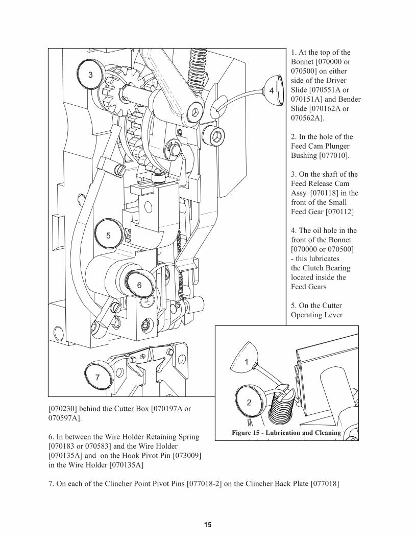
1. At the top of the Bonnet [070000 or 070500] on either side of the Driver Slide [070551A or 070151A] and Bender Slide [070162A or 070562A].
2. In the hole of the Feed Cam Plunger Bushing [077010].
3. On the shaft of the Feed Release Cam Assy. [070118] in the front of the Small Feed Gear [070112]
4. The oil hole in the front of the Bonnet [070000 or 070500] - this lubricates the Clutch Bearing located inside the Feed Gears
5. On the Cutter Operating Lever
[070230] behind the Cutter Box [070197A or 070597A].
6. In between the Wire Holder Retaining Spring [070183 or 070583] and the Wire Holder [070135A] and on the Hook Pivot Pin [073009] in the Wire Holder [070135A]
7. On each of the Clincher Point Pivot Pins [077018-2] on the Clincher Back Plate [077018]
15
Figure 15 - Lubrication and Cleaning
1
3
4
5
6
2
7
16
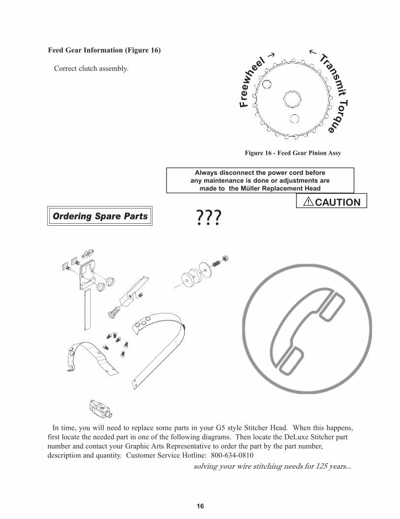
Feed Gear Information (Figure 16)
Correct clutch assembly.1
Figure 16 - Feed Gear Pinion Assy
Free
whe
el Transm
it Torque
Always disconnect the power cord before any maintenance is done or adjustments are
made to the Müller Replacement Head
!CAUTION
???
In time, you will need to replace some parts in your G5 style Stitcher Head. When this happens, first locate the needed part in one of the following diagrams. Then locate the DeLuxe Stitcher part number and contact your Graphic Arts Representative to order the part by the part number, description and quantity. Customer Service Hotline: 800-634-0810
Ordering Spare Parts
solving your wire stitching needs for 125 years...
!

Troubleshooting (Figure 17)
The quality and quantity of work that can be produced with the Müller Replacement Head is dependent upon the operator making all adjustments as accurately as possible and carefully maintaining the head. The cause of staple imperfections usually can be traced to inaccurate settings or normal wear of moving parts. In the event of trouble of this nature occurring, the operator can, by referring to the following troubleshooting chart, quickly locate and remedy the cause or causes of the trouble.
The following is a brief list of problems and solutions which should cover the majority of situations encountered when stitching with the DB style Stitching Heads.
17

18
problem: Right Leg Shortsolution: Move the Feed Gear Stop to the right, slightly. (See page 11)
problem: Right leg Longsolution: Move the Feed Gear Stop to the left, slightly. (See page 11)
problem: Corner Buckledsolution: Check the Driver for a chipped corner and rotate or replace it if needed. Use a heavier gauge wire.
problem: Leg(s) Buckledsolution: Check the Wire Cutters and Wire Cutter Operating Slide for wear and rotate or replace if needed. Use a heavier gauge wire.
problem: Crown Buckledsolution: Check Supporter Spring tension on the Head. If it is too loose replace it.
problem: Stitch in Piecessolution: Clean and lubricate the Head. Check for hard or brittle wire and replace. Check the tension of the Wire Holder Spring and replace Spring if too loose. Look for wear in Wire Holder pivot point in Bonnet.
problem: Loose Clinchsolution: Raise the Clincher Points. (See page 13)
problem: Legs are Spread or Contractedsolution: Make sure the wire is feeding straight through the Head. (See page 10) Check the Wire Cutters for wear and rotate or replace if needed. Check the Formers for wear in the grooves and replace if needed.
problem: Wire jam near Feed Gearsolution: Tighten Cutters. Check for the following worn parts and replace if necessary. Fixed Cutter, Moving Cutter, Cutter Operating Slide, Cutter Operating Lever, Bender Slide Insert, Wire Guide, Hook, Hook Pivot Pin and Feed Gear Friction Strip.
Figure 17 - Troubleshooting

19
Bonnet and Wire Guide Spring Sub-Assemblies DB75
070286
072017 (2)
077010
074004
077009
070181
070186
G20589
070183
071003
072004
073002
G20195
077006B
073010
070230
070119
073006
070112
070118
070000
070144
070244 (2)
072009
070114
072013
071005
G20297
G20292 (2)
G20298
G20293 (2)
G20287
G20195
072009
073007
073005
071004 (2)
071006 (2)
SHADED PART NUMBERS DENOTES WEAR PARTS
070720
070719UA3808.1
PW10.6PARTS USED FOR: MINUTEMAN OR 1509 STITCHERS

20
Bonnet and Wire Guide Spring Sub-Assemblies; DB75
070000 0881.0004.1 Bonnet - DB75070112 0881.0003.4 Feed Gear, Small070114 0881.0008.4 Feed Gear Shaft070118 0881.0018.4 Feed Release Cam Assembly070119 0022.0270 Feed Release Handle070144 0881.0042.4 Wire Tube070181 0881.0009.4 Upper Wire Tube070183 0034.6302 Wire Holder Retaining Spring070186 0034.6301 Friction Strip070230 0881.0006.4 Cutter Operating Lever070244 0881.0043.4 Wire Tube Clamp070286 0881.0301.3 Wire Guide SpringG20520 Lock Washer, M6071004 0031.5103 Lock Washer, Ribbed, M3071005 0031.5104 Lock Washer Ribbed, M4071006 0031.5105 Lock Washer, Ribbed, M5072004 0030.0048 Screw M6x1.0x12072009 0030.3434 Screw M3x.5x10072013 0030.9001 Screw M6x1.0x22072017 0881.0041.4 Screw M5x0.8x5.5073002 0031.0759 E-Ring073005 0031.6310 Spring Pin, M3x10073006 0031.6312 Spring Pin, M3x12073007 0031.6316 Spring Pin, M3x16073010 0881.0030.4 Dowel Pin, M6x32074004 0034.2370 Compression Spring077009 0881.0032.4 Feed Cam Plunger077010 0881.0035.4 Feed Cam Plunger Bushing077006B 0881.0021.4 Mounting StrapG20195 Screw M6x1x8G20287 Wire Oiler Felt SpringG20292 Wire Oil Felt WasherG20293 Wire Oiler Felt, 1-1/4 Dia.G20297 Screw M6x1x40G20298 Nylock Lock Nut M6x1G20589 Screw M4x0.7x10
DELUXE PART NUMBER
MÜLLER PART NUMBER CROSS REFERENCE
PARTDESCRIPTION
21
070286
072017 (2)
077010 or078010 [DB75VS]
044002 or074004
070181
073002
G20195077027B
070119
073006070112 or078112A
070118 or078118A [DB75VS]
070244 (2)
070544
072009 (2)
072013
G20297
G20292 (2)
G20298
G20293 (2)
G20287
G20195
071004 (2)
071006 (2)
073010
070230 or 078230C [DB75VS](5/8"/15mm
Crown-OSK138)
Bonnet and Wire Guide Spring Sub-Assemblies DB75V & DB75VS
grease
grease
grease
grease
grease
077009
078008 (2)(Used on
DB75VS only.)
SHADED PART NUMBERS DENOTES WEAR PARTS

22
Bonnet and Wire Guide Spring Sub-Assemblies; DB75V & DB75VS
070286 0881.0301.3 Wire Guide Spring044002 0354.1041.4 Feed Cam Compression Spring070112 0881.0003.4 Feed Gear, Small070118 0881.0018.4 Feed Release Cam Assembly070119 0022.0270 Feed Release Handle070181 0881.0009.4 Upper Wire Tube070230 0881.0006.4 Cutter Operating Lever070244 0881.0043.4 Wire Tube Clamp070544 0249.1014.4 Lower Wire Tube071004 0031.5103 Lock Washer, Ribbed, M3071006 0031.5105 Lock Washer, Ribbed, M5072009 0030.3434 Screw M3x.5x10072013 0030.9001 Screw M6x1.0x22072017 0881.0041.4 Screw M5x0.8x5.5073002 0031.0759 E-Ring073006 0031.6312 Spring Pin, M3x12073010 0881.0030.4 Dowel Pin, M6x32074004 0034.2370 Compression Spring077009 0881.0032.4 Feed Cam Plunger077010 0881.0035.4 Feed Cam Plunger Bushing078010 0881.4024.4 Feed Cam Plunger Bushing077027B 0881.0325.4 Mounting Strap, DB75V078008 0023.0957 Shim Washer, DB75VS078112A 0881.0364.4 Small Feed Gear, DB75VS078118A 0881.0363.3 Feed Release Cam Shaft Assembly078230C 0881.0370.4 Cutter Operating Lever-CarbideG20195 Screw M6x1x8G20287 Wire Oiler Felt Spring G20292 Wire Oil Felt WasherG20293 Wire Oiler Felt, 1-1/4 Dia.G20297 Screw M6x1x40G20298 Hex Nut M6x1
DELUXE PART NUMBER
MÜLLER PART NUMBER CROSS REFERENCE
PARTDESCRIPTION

23
Bonnet and Supporter Sub-Assemblies DB75V & DB75VS
070186(DB75VS requires the addition of plastic liner
Part # OSK137-3.See Page 20.)
G20589
070583
G20520
072004
G20195
077021(5/8"/15mm Crown-
030021)
073012
070554(5/8"/15mm Crown-
030554)
072005 (2)
071005
073007
G20520 (2)
073005
070344
072010
077025(5/8"/15mm Crown-
077025B)
070500
070114
grease
grease
grease
grease
grease
grease
SHADED PART NUMBERS DENOTES WEAR PARTS

Bonnet and Supporter Sub-Assemblies; DB75V & DB75VS
24
070114 0881.0008.4 Feed Gear Shaft070186 0034.6301 Friction Strip070344 0881.0313.4 Supporter Spring070500 0881.0300.2 Bonnet - DB75V070554 0881.0312.4 Supporter070583 0881.0321.4 Wire Holder Retaining Spring071005 0031.5104 Lock Washer Ribbed, M4072004 0030.0048 Screw M6x1.0x12072005 0030.0051 Screw M6x1.0x25072010 0030.3447 Screw M4x0.7x5073005 0031.6310 Spring Pin, M3x10073012 0881.0314.4 Dowel Pin, M6x55077021 0881.0311.4 Supporter Holder077025 0881.0320.4 Wire Holder GuideG20195 0030.1725 Screw M6x1x8G20520 0031.0557 Lock Washer Ribbed, M6G20589 0030.0017 Screw M4x0.7x10, Nylon
DELUXE PART NUMBER
MÜLLER PART NUMBER CROSS REFERENCE
PARTDESCRIPTION

25
070151A(ASSEMBLY)
077002
077012070152-25 (0.6 mm)070152-23 (0.8 mm)070152-20 (1.0 mm)
072018 (2)
072007
077003
072016
071005
077011
071002
070550R-25 (0.6 mm)070550R-23 (0.8 mm)070550R-20 (1.0 mm)
070548L-25 (0.6 mm)070548L-23 (0.8 mm)070548L-20 (1.0 mm)
074003
073003
073008
071005 (3)
072011 (3)
070162A(ASSEMBLY)
077004
077007
072010
Driver and Bender Inserts DB75
grease
grease
grease
grease
grease
grease
grease
SHADED PART NUMBERS DENOTES WEAR PARTS

Driver and Bender Inserts; DB75
26
071002 0023.0931 Shim Washer071005 0031.5104 Lock Washer Ribbed, M4072007 0030.1711 Screw M5x0.8x4072010 0030.3447 Screw M4x0.7x5072016 0881.0039.4 Screw M4x0.7x17073003 0031.5021 Cotter Pin073008 0031.9106 Rivet074003 0034.2152 Center Guide Spring077002 0881.0013.4 Centering Guide Post077003 0881.0017.4 Centering Guide077004 0881.0019.4 Driver Slide Shaft077007 0881.0022.4 Set Collar077011 0881.0037.4, 0881.0037.3 Hook Guide, DB75077012 0881.0040.4 Bender Slide Insert070151A 0881.0051.4 Driver Slide Assembly070152-20 0881.0153.4 Driver 1.0 Wire070152-23 0211.0039.3 Driver 0.8 Wire070152-25 0881.0014.3 Driver 0.6 Wire070162A 0881.0050.4 Bender Slide Assembly070548L-20 0881.0152.4 Former LH 1.0 Wire070548L-23 0881.0184.4 Former LH 0.8 Wire070548L-25 0881.0016.4 Former LH 0.6 Wire070550R-20 0881.0151.4 Former RH 1.0 Wire070550R-23 0881.0185.4 Former RH 0.8 Wire070550R-25 0881.0014.3 Driver 0.6 Wire071005 0031.5104 Lock Washer Ribbed, M4072011 0030.3451 Screw M4x0.7x12072018 0881.0045.4 Screw M4x0.7x6, Nylon
DELUXE PART NUMBER
MÜLLER PART NUMBER CROSS REFERENCE
PARTDESCRIPTION

070551A(Assembly,
includes 077004)
077012070552-25 (0.6 mm)070552-23 (0.8 mm)070552-20 (1.0 mm)5/8"/15mm Crown070656-25 (0.6 mm)070656-23 (0.8 mm)070656-20 (1.0 mm)
072015
077022(5/8"/15mm Crown-030022)
077023
072019
071005
077024(5/8"/15mm Crown-077024B)
071002
070550R-25 (0.6 mm)070550R-23 (0.8 mm)070550R-20 (1.0 mm)5/8"/15mm Crown
070648R-25 (0.6 mm)070648R-23 (0.8 mm)070648R-20 (1.0 mm)
070548L-25 (0.6 mm)070548L-23 (0.8 mm)070548L-20 (1.0 mm)5/8"/15mm Crown
070650L-25 (0.6 mm)070650L-23 (0.8 mm)070650L-20 (1.0 mm)
074003
071005 (3)
072011 (3)
070562A (5/8"/15mm Crown-070662A)(Assembly, includes 077012 & 073008)
077004
077007
072010
Driver and Bender Inserts DB75V
grease
grease
grease
grease
grease
grease
grease
27
073003
SHADED PART NUMBERS DENOTES WEAR PARTS

071002 0023.0931 Shim Washer071005 0031.5104 Lock Washer Ribbed, M4072010 0030.3447 Screw M4x0.7x5072011 0030.3451 Screw M4x0.7x12072015 0249.1054.4 Driver Retaining Screw072019 0881.0318.4 Allen Head Screw073003 0031.5021 Cotter Pin074003 0034.2152 Center Guide Spring077004 0881.0019.4 Driver Slide Shaft077007 0881.0022.4 Set Collar077012 0881.0040.4 Bender Slide Insert077022 0881.0315.4 Centering Guide, Wide077023 0881.0316.4 Centering Guide, Narrow077024 0881.0317.4 Hook Guide, DB75V070548L-20 0881.0152.4 Former LH 1.0 Wire070548L-23 0881.0184.4 Former LH 0.8 Wire070548L-25 0881.0016.4 Former LH 0.6 Wire070550R-20 0881.0151.4 Former RH 1.0 Wire070550R-23 0881.0185.4 Former RH 0.8 Wire070550R-25 0881.0015.4 Former RH 0.6 Wire070551A 0249.1065.4 Driver Slide Assembly070552-20 0881.0319.3 Driver 1.0 Wire070552-23 0881.0367.3 Driver 0.8 Wire070552-25 0881.0326.3 Driver 0.6 Wire070562A 0881.0309.4 Bender Slide Assembly070648R-20 0881.0160.4 Former RH 1.0 Wire070648R-23 0881.0187.4 Former RH 0.8 Wire070648R-25 0881.0156.4 Former RH 0.6 Wire070650L-20 0881.0161.4 Former LH 1.0 Wire, 15mm Crown070650L-23 0881.0186.4 Former LH 0.8 Wire, 15mm Crown070650L-25 0881.0155.4 Former LH 0.6 Wire, 15mm Crown070656-20 0881.0511.3 Driver 1.0 Wire-15mm Crown070656-23 0881.0331.3 Driver 0.8 Wire-15mm Crown070656-25 0881.0510.3 Driver 0.6 Wire-15mm Crown
Driver and Bender Inserts; DB75V
28
DELUXE PART NUMBER
MÜLLER PART NUMBER CROSS REFERENCE
PARTDESCRIPTION

29
078001
Driver and Bender Inserts DB75VS
078005 (2)
078002
078006
G20298
078551A
078562A
078551MATL(includes 078004)
078562A
078562MATL(includes 078012C)
078012C
070552-25 (0.6 mm)070552-23 (0.8 mm)070552-20 (1.0 mm)
072015
078024
072019
071005
070550R-25 (0.6 mm)070550R-23 (0.8 mm)070550R-20 (1.0 mm)
070548L-25 (0.6 mm)070548L-23 (0.8 mm)070548L-20 (1.0 mm)
074003
077022
071002
071005 (3)
072011 (3)
073003
GREASE AS SHOWN ON PRECEDING DB75V PAGE
077023
078001
SHADED PART NUMBERS DENOTES WEAR PARTS
078002
G20298
078005(2)

Driver and Bender Inserts; DB75VS
30
071002 0023.0931 Shim Washer071005 0031.5104 Lock Washer Ribbed, M4072015 0249.1054.4 Driver Retaining Screw, Nylon072019 0881.0318.4 Allen Head Screw073003 0031.5021 Cotter Pin074003 0034.2152 Center Guide Spring077022 0881.0315.4 Centering Guide, Wide077023 0881.0316.4 Centering Guide, Narrow078001 0881.0374.4 Bearing, Mount Shaft, DB75VS078002 0038.1243 Slide Bearing, DB75VS078006 0023.0955 Shim, DB75VS078024 0881.4045.3 Hook Guide, DB75VS070548L-20 (1.0 mm) 0881.0152.4 Former LH 1.0 Wire070548L-23 (0.8 mm) 0881.0184.4 Former LH 0.8 Wire070548L-25 (0.6 mm) 0881.0016.4 Former LH 0.6 Wire070550R-20 (1.0 mm) 0881.0151.4 Former RH 1.0 Wire070550R-23 (0.8 mm) 0881.0185.4 Former RH 0.8 Wire070550R-25 (0.6 mm) 0881.0015.4 Former RH 0.6 Wire070552-20 (1.0 mm) 0881.0319.3 Driver 1.0 Wire070552-23 (0.8 mm) 0881.0367.3 Driver 0.8 Wire070552-25 (0.6 mm) 0881.0326.3 Driver 0.6 Wire072011 0030.3451 Screw M4x0.7x12078005 0209.2367.4 Bearing Slide Washer, DB75VS078012C 0881.0371.4 Bender Insert-Carbide, DB75VS078551A 0881.0336.3 Driver Slide Assembly, DB75VS078562A 0354.1036.3 Bender Slide Assembly, DB75VSG20298 Nylock Lock Nut M6x1
DELUXE PART NUMBER
MÜLLER PART NUMBER CROSS REFERENCE
PARTDESCRIPTION
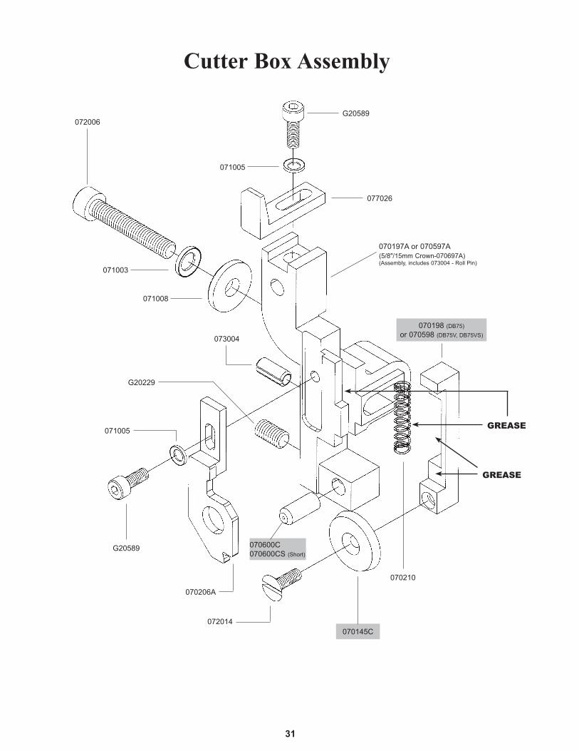
31
070206A
073004
071008
077026
070197A or 070597A(5/8"/15mm Crown-070697A)(Assembly, includes 073004 - Roll Pin)
072014
070210
072006
070145C
Cutter Box Assembly
071005
071003
071005
G20589
070198 (DB75)or 070598 (DB75V, DB75VS)
G20589
G20229
070600C070600CS (Short)
grease
grease
Cutter Box Assembly
32
070197A 0881.0010.4 Cutter Box Assembly070597A 0881.0322.4 Cutter Box Assembly70210 0034.2252 Cutter Box Spring70198 0881.0007.4 Cutter Operating Slide77026 0881.0324.4 Feed Gear Stop070600C 0881.0198.4 Fixed Cutter - Carbide070600CS 0881.0505.4 Fixed Cutter - Carbide-Short071005 0031.5104 Lock Washer Ribbed, M4071005 0031.5104 Lock Washer Ribbed, M4070145C 0881.0197.4, 0305.2127.4 Moving Cutter - CarbideG20520 Ribbed Lock Washer, M6G20589 0030.0017 Screw M4x0.7x10, NylonG20589 0030.0017 Screw M4x0.7x10072014 0030.9016 Screw M4x0.7x12 LH071008 0881.0323.4 Washer072006 0030.0052 Screw M6x1.0x30G20229 0030.1727 Screw M6x1x12, Nylon073004 0031.6039 Spring Pin, M5x12070206A 0249.1074.4 Wire Straightener Assembly
DELUXE PART NUMBER
MÜLLER PART NUMBER CROSS REFERENCE
PARTDESCRIPTION

33
077001(Assembly, includes
043002)
070510A *
(FOR DB75 ONLY) 070111A *(FOR DB75V ONLY) 070511A *
074002
070537 *
073001
Feed Gear Assembly - DB75, DB75V & DB75VS
043002
* Indicates parts that are not interchangeable with Müller-Martini parts.All parts used together can be used interchangeably with the HK75 or HK75V.
Used together replaces 0881.0308.30881.0304.4 (DB75V) or 0881.0368.4 (DB75)
0881.0330.4
grease
grease
aero shell grease
s.a.e. oil
USE REPLACEMENT KIT MMKFG1 FOR DB75 AND HK75.USE REPLACEMENT KIT MMKFG2 FOR DB75V, DB75VS, HK75V, AND HK75VS.
043002 0031.6491 Grooved Pin070537 0881.0330.4DB Feed Gear Clutch073001 0031.0757 E-Ring074002 0034.0302 Extension Spring077001 0881.0011.4 Feed Gear Operating Lever Assy070510A 0881.0308.3DB Feed Gear, Large
Feed Gear Assembly - DB75, DB75V & DB75VSDELUXE PART NUMBER
MÜLLER PART NUMBER CROSS REFERENCE
PARTDESCRIPTION

Complete Assembly070135A
34
Wire Holder Assemblies; DB75 & DB75V
077013
070135
072008
073009
074001
grease
grease
DB75VSComplete Assembly
070559A5/8"/15mm Crown
070659A
070559
074001
072008
070013
073009
SHADED PART NUMBERS DENOTES WEAR PARTS
Wire Holder Assembly
070135 0881.0031.3 DB Head Wire Holder072008 0030.3429 Screw M3x0.5x3073009 0031.0757 E-Ring074001 0034.0102 Extension Spring077013 Wire Hook070559 DB Head Wire Holder073009 Hook Pivot Pin070013 Wire Holder Hook Assembly, VS072008 0030.3429 Screw M3x0.5x3074001 0034.0102 Extension Spring
DELUXE PART NUMBER
MÜLLER PART NUMBER CROSS REFERENCE
PARTDESCRIPTION
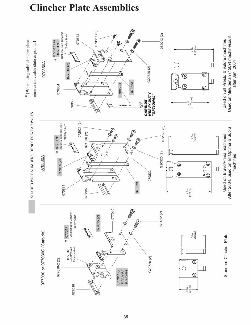
Clincher Plate Assemblies
35
0708
53
0720
12 (2
)
0770
15 (2
)
0770
19
0770
18(w
/ 077
018-
2 P
ins
inst
alle
d)07
7016
G20
520
(2)
0770
18-2
(2)
0708
31
0708
35 0708
33
0770
15 (2
)
0708
32
0710
06 (2
)
0720
21 (2
)
0720
20 (2
)
G20
520
(2)
0708
30A
0770
30 o
r 077
030C
(Car
bide
)
SHA
DED
PA
RT N
UM
BER
S D
ENO
TES
WEA
R P
ART
S
0708
50A
0708
51
0708
52
0770
15 (2
)07
0855
0708
57 (2
)
0720
13 (2
)G
2052
0 (2
)
0770
17(O
ptio
nal S
olid
Clin
cher
)
0770
14 o
r07
7029
C
(Car
bide
)
Sta
ndar
d C
linch
er P
late
Use
d on
Bra
vo/P
rima
mac
hine
sA
fter 2
004,
use
d on
all
Opt
ima
& S
upra
m
achi
nes
Use
d on
all
Pre
sto
& V
alor
e m
achi
nes
Use
d on
Min
utem
an (1
509)
mac
hine
sbui
lt af
ter J
an. 2
004
(Opt
iona
l Sol
id C
linch
er)
0770
17B
(Opt
iona
l Sol
id C
linch
er)
0770
17 O
R
0770
17B
*(W
hen
usin
g so
lid c
linch
er p
late
s
rem
ove
mov
eabl
e sl
ide
& p
oint
s.)
"Saf
ety
Stit
ch"
"Saf
ety
Stit
ch"
"Saf
ety
Stit
ch"
2.0i
n50
mm
2.6i
n65
mm
4.8i
n12
2mm
5.3i
n13
5mm
4.1i
n10
3mm
4.2i
n10
8mm
**
*
0708
53C
CA
RB
IDE
-
HE
AV
Y D
UT
Y"O
PT
ION
AL
"

Clincher Plate Assemblies
070830A (0305.0321)
077030 (0881.9050) or 077030C (Carbide) (0881.9050CAR)
070850A (0881.8339)
070831 Clincher Back Plate, Bravo Plus070832 Clincher Front Plate, Bravo Plus070833 Clincher Slide, Carbide, Bravo Plus 5-5/16- 135mm070835 Clincher Mounting Bar, Bravo Plus071006 0031.5105 Lock Washer, Ribbed M5072020 Screw, M6x1.0x14, SHC072021 Screw, M5x0.8x10, SHC Low Head077015 0881.0125.3 Clincher Point 1/2”077017B Solid Clincher Plate Insert, Bravo & Primo 2004 or NewerG20520 Lock Washer Ribbed, M6
077017 0881.0140.3 Solid Clincher Plate Insert070851 Clincher Back Plate, Medium Length070852 Clincher Front Plate, Medium Length070853 1550.3023.3 Clincher Slide Assy., Medium Length070853C Clincher Slide Assy., Carbide, 108mm Long070855 Clincher Mounting Bar070857 Screw, M6x1.0x8, FHM072013 0030.9001 Screw M6x1.0x22077015 0881.0125.3 Clincher Point 1/2”077017B Solid Clincher Plate Insert, Bravo & Primo 2004 or Newer
36
077014 0881.0123.4 Clincher Slide Assembly077016 0881.0136.4 Clincher Mounting Bar077017 0881.0140.3 Plate Insert077018 0881.0141.3 Clincher Back Plate077019 0881.0142.3 Clincher Front Plate072012 0030.3488 Screw M6x1.0x20077015 0881.0125.3 Clincher Point 1/2”077029C 0881.0351.3 Clincher Slide Assembly, CarbideG20520 0031.0557 Lock Washer Ribbed, M6
DELUXE PART NUMBER
MÜLLER PART NUMBER CROSS REFERENCE
PARTDESCRIPTION
DELUXE PART NUMBER
MÜLLER PART NUMBER CROSS REFERENCE
PARTDESCRIPTION
DELUXE PART NUMBER
MÜLLER PART NUMBER CROSS REFERENCE
PARTDESCRIPTION

NOTES:
37

38
DeLuxe Stitcher / Müller Part Number Cross-Reference030021 Supporter Block, 15mm Crown
030022 0881.0518.4 Centering Guide, 15mm Crown
030554 Supporter, 15mm Crown
043002 0031.6491 Grooved Pin
044002 0354.1041.4 Feed Cam Compression Spring
070000 0881.004.1 Bonnet - DB75
070111A 0881.0368.4DB Feed Gear Pinion Assembly
070112 0881.0003.4 Feed Gear, Small
070114 0881.0008.4 Feed Gear Shaft
070118 0881.0018.4 Feed Release Cam Assembly
070119 0022.0270 Feed Release Handle
070135A 0881.0058.3 Wire Holder Assembly
070144 0881.0042.4 Wire Tube
070145C 0881.0197.4 Moving Cutter - Carbide
070151A 0881.0051.4 Driver Slide Assembly
070152-20 0881.0153.4 Driver 20-24 Wire
070152-23 0211.0039.3 Driver 22-24 Wire
070152-25 0881.0014.3 Driver 25-28 Wire
070162A 0881.0050.4 Bender Slide Assembly
070181 0881.0009.4 Upper Wire Tube
070183 0034.6302 Wire Holder Retaining Spring
070186 0034.6301 Friction Strip
070197A 0881.0010.4 Cutter Box Assembly
070198 0881.0007.4 Cutter Operating Slide
070206A 0249.1074.4 Wire Straightener Assembly
070210 0034.2252 Cutter Box Spring
070230 0881.0006.4 Cutter Operating Lever
070244 0881.0043.4 Wire Tube Clamp
070286 0881.0301.3 Wire Guide Spring
070344 0881.0313.4 Supporter Spring
070500 0881.0300.2 Bonnet - DB75V
070510A 0881.0308.3DB Feed Gear, Large
070511A 0881.0304.4DB Feed Gear Pinion Assembly
070537 0881.0330.4DB Feed Gear Clutch
070544 0249.1014.4 Lower Wire Tube
070548L-20 0881.0152.4 Former LH 20-24 Wire
070548L-23 0881.0184.4 Former LH 22-24 Wire
070548L-25 0881.0016.4 Former LH 25-28 Wire
070550R-20 0881.0151.4 Former RH 20-24 Wire
070550R-23 0881.0185.4 Former RH 22-24 Wire
070550R-25 0881.0015.4 Former RH 25-28 Wire
070551A 0249.1065.4 Driver Slide Assembly
070552-20 0881.0319.3 Driver 20-24 Wire
070552-23 0881.0367.3 Driver 22-24 Wire
070552-25 0881.0326.3 Driver 25-28 Wire
070554 0881.0312.4 Supporter
070559A 0881.4112.3 Wire Holder Assembly, DB75VS
070562A 0881.0309.4 Bender Slide Assembly
070583 0881.0321.4 Wire Holder Retaining Spring
070597A 0881.322.4 Cutter Box Assembly
070598 0249.1073.4 Cutter Operating Slide
070600C 0881.0198.4 Fixed Cutter - Carbide
070600CS 0881.0505.4 Fixed Cutter - Carbide-Short
070648R-20 0881.0160.4 Former RH 20-24 Wire
070648R-23 0881.0187.4 Former RH 22-24 Wire
070648R-25 0881.0156.4 Former RH 25-28 Wire
070650L-20 0881.0161.4 Former LH 20-24 Wire, 15mm Crown
070650L-23 0881.0186.4 Former LH 22-24 Wire, 15mm Crown
070650L-25 0881.0155.4 Former LH 25-28 Wire, 15mm Crown
070656-20 0881.0511.3 Driver 20-24 Wire-15mm Crown
070656-23 0881.0331.3 Driver 22-24 Wire-15mm Crown
070656-25 0881.0510.3 Driver 25-28 Wire-15mm Crown
070659A Wire Holder Assy, 15mm Crown
070662A Bender Slide Assembly
070697A Cutter Box Assy, 15mm Crown
070830A Clincher Plate Assy., Carbide
070831 Clincher Back Plate, Bravo
070832 Clincher Front Plate, Bravo
070833 Clincher Slide, Carbide, Bravo
070835 Clincher Mounting Bar, Bravo
070850A Clincher Plate Assy., Presto
070851 Clincher Back Plate, Presto
070852 Clincher Front Plate, Presto
070853 Clincher Slide Assy., Presto
070853C Clincher Slide Assy., CARBIDE, 108mm
070855 Clincher Mounting Bar, Presto
070857 Screw, M6x1.0x8, FHM
070001 0022.0042 Washer, Large
071002 0023.0931 Washer, Shim
071003 Ribbed Lock Washer, M6
071004 0031.5103 Lock Washer, Ribbed
071005 0031.5104 Lock Washer Ribbed, 4mm
071006 0031.5105 Lock Washer, Ribbed
071007 0031.9051 Lock Washer Ribbed, 3.5mm
071008 0881.0323.4 Washer
072001 0030.0016 Screw M4x0.7x8
072003 0030.0018 Screw M4x0.7x12
072004 0030.0048 Screw M6x1.0x12
072005 0030.0051 Screw M6x1.0x25
072006 0030.0052 Screw M6x1.0x30

DeLuxe Stitcher / Müller Part Number Cross-Reference072007 0030.1711 Screw M5x0.8x4
072008 0030.3429 Screw M3x0.5x3
072009 0030.3434 Screw M3x.5x10
072010 0030.3447 Screw M4x0.7x5
072011 0030.3451 Screw M4x0.7x12
072012 0030.3488 Screw M6x1.0x20
072013 0030.9001 Screw M6x1.0x22
072014 0030.9016 Screw M4x0.7x12 LH
072015 0249.1054.4 Driver Retaining Screw
072016 0881.0039.4 Screw M4x0.7x18
072017 0881.0041.4 Screw M5x0.8x5.5
072018 0881.0045.4 Screw M4x0.7x6
072019 0881.0318.4 Screw M4x0.7x16
072020 Screw, M6x1.0x14, SHC
072021 Screw, M5x0.8x10, SHC Low
073001 0031.0757 E-Ring
073002 0031.0759 E-Ring
073003 0031.5021 Cotter Pin
073004 0031.6039 Spring Pin, M5x12
073005 0031.6310 Spring Pin, M3x10
073006 0031.6212 Spring Pin, M3x12
073007 0031.6316 Spring Pin, M3x16
073008 Spin Rivet
073009 0881.0027.4 Hook Pivot Pin, Nylon
073010 0881.0030.4 Dowel Pin, M6x32
073012 0881.0314.4 Dowel Pin, M6x55
074001 0034.0102 Extension Spring
074002 0034.0302 Extension Spring
074003 0034.2152 Center Guide Spring
074004 0034.2370 Compression Spring
077001 0881.001.4 Feed Gear Operating Lever Assy
077002 0881.0013.4 Centering Guide Post
077003 0881.0017.4 Centering Guide
077004 0881.0019.4 Driver Slide Shaft
077006B 0881.0021.4 Mounting Strap
077007 0881.0022.4 Set Collar
077009 0881.0032.4 Feed Cam Plunger
077010 0881.0035.4 Feed Cam Plunger Bushing
077011 0881.0037.4 Hook Guide, DB75
077012 0881.0040.4 Bender Slide Insert
077013 Wire Hook
077014 0881.0123.4 Clincher Slide Assembly
077015 0881.0125.3 Clincher Point 1/2”
077016 0881.0136.4 Clincher Mounting Bar
077017 0881.0140.3 Solid Clincher
39
077017B Solid Clincher Optional
077018 0881.0141.3 Clincher Back Plate
077019 0881.0142.3 Clincher Front Plate
077021 0881.0311.4 Supporter Block
077022 0881.0315.4 Centering Guide, Wide
077023 0881.0316.4 Centering Guide, Narrow
077024 0881.0317.4 Hook Guide, DB75V
077024B Hook Guide, 15mm Crown
077025 0881.0320.4 Wire Holder Guide
077025B 0881.0512.4 Wire Holder Guide, 15mm Crown
077026 0881.0324.4 Feed Gear Stop
077027B 0881.0325.4 Mounting Strap, DB75V
077029C 0881.0351.3 Clincher Slide - Carbide
077030 0881.9050 Clincher Plate Assy
077030C 0881.9050CAR Clincher Plate Assy-Carbide
078001 0881.0374.4 Bearing, Mount Shaft
078002 0038.1243 Bearing, Bender/Driver Bar
078003 0038.3610 Bearing, Small Gear
078005 0209.2367.4 Shim Washer
078006 0023.0955 Shim Washer
078008 0023.0957 Shim Washer
078010 0881.0366.4 Feed Cam Plunger Bushing
078012C 0881.0371.4 Bender Slide Insert-Carbide
078024 0881.4005.4 Hook Guide
078112A 0881.0364.4 Small Feed Gear Asy (Combine)
'' 0038.3610 Small Gear Bearing (Combine)
078118A 0881.0363.3 Feed Release Cam Assembly
078230C 0881.0370.4 Cutter Operating Lever-Carbide
078551A 0881.0336.3 Driver Slide Assembly
078562A 0354.1036.3 Bender Slide Assembly
G20195 0030.1725 Screw M6x1x8
G20229 0030.1727 Screw M6x1x12
G20287 0034.2254 Wire Oiler Felt Spring
G20292 0881.0302.4 Wire Oil Felt Washer
G20293 0881.0303.4 Wire Oiler Felt
G20297 0030.3494 Screw M6x1x40
G20298 0030.3494 Hex Nut M6x1
G20360 Hex Key Wrench 3.0mm
G20361 Hex Key Wrench 2.5mm
G20362 Clamp Wrench 5.0mm
G20373 Hex Key Wrench 4.0mm
G20520 0031.0557 Lock Washer Ribbed, 6mm
G20589 0030.0017 Screw M4x0.7x10
MMKFG1 (See page 28) Müller Feed Gear Kit
MMKFG2 (See page 28) Müller Feed Gear Kit

RE
GIS
TR
AT
ION
To b
ette
r ser
vice
you
r wire
stit
chin
g ne
eds,
ple
ase
take
a m
omen
t to
fill o
ut a
nd re
turn
this
regi
stra
tion
card
.
Nam
e :
( F
irst )
( M
iddl
e In
itial )
( L
ast )
Com
pany
:
Stre
et A
ddre
ss :
City
:
Stat
e/Pr
ovin
ce :
Zi
p :
Coun
try
:
Phon
e :
Fax
: E-
mai
l :
Mac
hine
(s) P
urch
ased
:
Seria
l Num
ber(
s) :
With
Hea
d(s)
:
( Typ
e/Q
uant
ity P
urch
ased
)
Seria
l Num
ber(
s) :
Hea
d(s)
Pur
chas
ed :
Seria
l Num
ber(
s) :
Dat
e Re
ceiv
ed :
Dea
ler N
ame
:
Dea
ler S
tree
t Add
ress
:
City
:
Stat
e/Pr
ovin
ce :
Zip
:
Coun
try
:
Dea
ler P
hone
:
Oth
er B
inde
ry P
rodu
cts
Use
d :
Wou
ld y
ou li
ke in
form
atio
n se
nt to
you
abo
ut n
ew p
rodu
cts
that
wou
ld b
enef
it yo
ur c
ompa
ny?
Y
es
No
Ple
ase
take
a m
omen
t to
fill o
ut th
e at
tach
ed c
ard
and
mai
l it t
o D
eLux
e S
titch
er C
ompa
ny, I
nc..
In
add
ition
, dup
licat
e th
e in
form
atio
n fo
r you
r rec
ords
to
ass
ist w
hen
mak
ing
furth
er in
quiri
es.
PR
OD
UC
TM
achi
ne(s
) Pur
chas
ed :
Seria
l Num
ber(
s) :
With
Hea
d(s)
:
( Typ
e/Q
uant
ity P
urch
ased
)
Seria
l Num
ber(
s) :
Hea
d(s)
Pur
chas
ed :
Seria
l Num
ber(
s) :
DE
LUX
E ST
ITC
HER
GR
APH
IC A
RTS
REP
RES
ENTA
TIV
ED
ate
Rece
ived
:
Dea
ler N
ame
:
Dea
ler S
tree
t Add
ress
:
City
:
Stat
e/Pr
ovin
ce :
Zip
:
Coun
try
:
Dea
ler P
hone
:
PRODUCTCUSTOMER DEALER

PLA
CE
STA
MP
HE
RE
De
Lu
xe
St
itc
he
r
CO
MPA
NY,
IN
C.
37
47
N A
corn
Lan
eFr
ankl
in P
ark,
IL 6
01
31
U.S
.A.
Att
n: C
ust
om
er S
ervi
ce
Com
mon
Rep
lace
men
t Par
ts fo
r 1/
2” C
row
n
Bel
ow is
a li
st o
f the
mos
t com
mon
wea
r/rep
lace
men
t par
ts fo
r the
D
B75
and
75V
Stit
cher
Hea
d. T
his
guid
e sh
ould
hel
p yo
u w
hen
orde
ring
repl
acem
ent p
arts
. If
the
part
you
need
is n
ot li
sted
bel
ow,
plea
se re
fer t
o th
e m
ore
deta
iled
parts
list
on
page
s 47
- 48
.
D
escr
iptio
n
Item
Num
ber
M
ovin
g C
utte
r - C
arbi
de
0701
45C
D
river
(DB
75) -
25-
28
0701
52-2
5 or
070
552-
25
Wire
Hol
der R
etai
ning
Spr
ing
0701
83
Cut
ter O
pera
ting
Leve
r 07
0230
Fi
xed
Cut
ter -
Car
bide
07
0600
C
Mov
ing
Cut
ter S
crew
07
2014
Sc
rew
, M4x
0.7x
6-N
ylon
07
2018
R
ivet
07
3008
H
ook
Pivo
t Pin
, Nyl
on
0730
09
Wire
Hol
der S
prin
g 07
4001
H
ook
Gui
de
0770
11
Ben
der S
lide
Inse
rt 07
7012
C
linch
er S
lide
Ass
embl
y 07
7014
C
linch
er P
oint
1/2
” 07
7015
C
linch
er P
oint
Piv
ot
0770
18-2
LIMITED WARRANTY
DeLuxe Stitcher Company, Inc. warrants to the original retail purchaser that this product is free from defects in material and workmanship and agrees to repair or replace, at DeLuxe Stitcher’s option, any defective product within 90 days from the date of purchase. This warranty is not
transferable. It covers damage resulting only from defects in material or workmanship and does not cover conditions or malfunctions resulting from
normal wear, neglect, abuse or accident.
This warranty is in lieu of all other express warranties. Any warranty of merchantability or fitness for a particular purpose is limited to the duration of this warranty. DeLuxe Stitcher shall not be liable for any incidental or
consequential damages.
Some states do not allow limitations on how long an implied warranty lasts, or the exclusion or limitation of incidental or consequential damages, so the above limitations or exclusions may not apply to you. This warranty gives you specific legal rights and you may also have other rights which
vary from state to state.
To obtain warranty service you must return the product, at your expense, together with proof of purchase to an authorized DeLuxe Stitcher Company Graphic Arts Dealer.

DBS75HD_0415
3747 Acorn Lane • Franklin Park • Illinois 60131Phone: 847-455-4400 • 800-634-0810
Fax: 847-455-4900 • 800-417-9251http://www.deluxestitcher.com
DELUXE STITCHERC O M P A N Y I N C .
®
ISP Stitching & Bindery Products