Embed Size (px)
Citation preview

Table of Contents
Introduction . . . . . . . . . . . . . . . . . . . . . . . . . . . . . . . . . . . . . . . . . . . . . . . . . . 2What’s in the Box? . . . . . . . . . . . . . . . . . . . . . . . . . . . . . . . . . . . . . . . . . . . . . 2About the Delta 66 Digital Recording Interface . . . . . . . . . . . . . . . . . . . . . . . 2Product Features & Specifications . . . . . . . . . . . . . . . . . . . . . . . . . . . . . . . . . 3Minimum System Requirements . . . . . . . . . . . . . . . . . . . . . . . . . . . . . . . . . . 3Quick Guide to Getting Started . . . . . . . . . . . . . . . . . . . . . . . . . . . . . . . . . . . 5Hardware Installation . . . . . . . . . . . . . . . . . . . . . . . . . . . . . . . . . . . . . . . . . . . 5Windows Software Installation . . . . . . . . . . . . . . . . . . . . . . . . . . . . . . . . . . . . 6
Windows 98 Installation . . . . . . . . . . . . . . . . . . . . . . . . . . . . . . . . . . . . . 6Windows 95 Installation . . . . . . . . . . . . . . . . . . . . . . . . . . . . . . . . . . . . . 7Windows NT Installation . . . . . . . . . . . . . . . . . . . . . . . . . . . . . . . . . . . . 7
Verifying Windows Driver Installation . . . . . . . . . . . . . . . . . . . . . . . . . . . . . . 8Verifying Delta Control Panel Software Installation . . . . . . . . . . . . . . . . . . . 9Delta System Overview . . . . . . . . . . . . . . . . . . . . . . . . . . . . . . . . . . . . . . . . . 9
Delta’s Analog Input/Outputs . . . . . . . . . . . . . . . . . . . . . . . . . . . . . . . . . 9The Digital Monitor Mixer . . . . . . . . . . . . . . . . . . . . . . . . . . . . . . . . . . 10The Patchbay / Router . . . . . . . . . . . . . . . . . . . . . . . . . . . . . . . . . . . . . . 10Synchronization . . . . . . . . . . . . . . . . . . . . . . . . . . . . . . . . . . . . . . . . . . 10
Using the Delta 66 with your Software Application . . . . . . . . . . . . . . . . . . . 11Delta 66 Control Panel Software . . . . . . . . . . . . . . . . . . . . . . . . . . . . . . . . . 13
Monitor Mixer Page . . . . . . . . . . . . . . . . . . . . . . . . . . . . . . . . . . . . . . . 13Patchbay/Router Page . . . . . . . . . . . . . . . . . . . . . . . . . . . . . . . . . . . . . . 16Hardware Settings Page . . . . . . . . . . . . . . . . . . . . . . . . . . . . . . . . . . . . 18S/PDIF Page . . . . . . . . . . . . . . . . . . . . . . . . . . . . . . . . . . . . . . . . . . . . . 20About Page . . . . . . . . . . . . . . . . . . . . . . . . . . . . . . . . . . . . . . . . . . . . . . 21Save, Delete, Load Buttons; H/W Installed . . . . . . . . . . . . . . . . . . . . . 21
Delta 66 Recording Tutorials . . . . . . . . . . . . . . . . . . . . . . . . . . . . . . . . . . . . 22Typical Setup #1 . . . . . . . . . . . . . . . . . . . . . . . . . . . . . . . . . . . . . . . . . . 22Typical Setup #2 . . . . . . . . . . . . . . . . . . . . . . . . . . . . . . . . . . . . . . . . . . 28Typical Setup #3 . . . . . . . . . . . . . . . . . . . . . . . . . . . . . . . . . . . . . . . . . . 32Transferring from DAT to Delta 66 . . . . . . . . . . . . . . . . . . . . . . . . . . . 33Transferring from Delta 66 to DAT . . . . . . . . . . . . . . . . . . . . . . . . . . . . 35
Troubleshooting . . . . . . . . . . . . . . . . . . . . . . . . . . . . . . . . . . . . . . . . . . . . . . 36Troubleshooting Tips for Frequently Asked Questions . . . . . . . . . . . . 39
Appendix A - Technical Specs . . . . . . . . . . . . . . . . . . . . . . . . . . . . . . . . . . . 41Appendix B - If You Use An External Mixer... . . . . . . . . . . . . . . . . . . . . . . 42Limited Lifetime Warranty . . . . . . . . . . . . . . . . . . . . . . . . . . . . . . . . . . . . . . 44
DELTA 66™ M A N U A LAUDIO
TM

Introduction
Congratulations on your purchase of the Delta 66 Digital Recording Interfacedesigned and built by M Audio. Even if you are experienced in digital recording,please take the time to read this manual. It will give you valuable information oninstalling your new card and the supporting software, plus help you to fullyunderstand the function and usability of the Delta 66. Once you’re up and running,you will quickly discover the power and brilliance, both in sound and design, ofyour Delta 66 Digital Recording Interface.
What’s in the Box?
Your Delta 66 box contains:
• This instruction manual.• The Delta 66 break-out box.• The Delta 66 PCI host adapter card.• 15-pin D-sub to 15-pin D-sub cable.• Diskette containing Windows 95/98 drivers & Delta Control Panel software.• M Audio Warranty Registration card.
About the Delta 66 Digital RecordingInterface
The Delta 66 functions as a 6-input, 6-output digital recording interface. Fouranalog inputs and outputs plus coaxial S/PDIF I/O give you the highest qualitydigital I/O available — all up to 24-bit data width and any sampling rate from 8kHzto 96kHz. Connect a line-level signal from your instrument, mixer, or pre-amp tothe Delta 66’s TRS jacks on the break-out box. Match the operating levels of yourinput and output signals using the +4, ‘Consumer,’ or -10 signal level softwareswitches. Record a digital audio signal from your DAT, MiniDisc, CD, or externalA/D converter via the Delta 66’s S/PDIF input located on the PCI Host card.Control all routing and hardware settings with the Delta’s comprehensive controlpanel software.
Within the Delta 66’s PCI chip is a hardware digital mixer. Controlled by theincluded Delta Control Panel software, it may handle all of your routing needs, giveyou extra control of all left, right, and stereo levels, in addition to control of pans,solos, and mutes.
2
Product Features & Specifications
• 6x6 24-bit/96khz full-duplex recording interface.• PCI host card with external break-out box. • 4x4 analog I/O accepts balanced or unbalanced connections on 1/4” TRS jacks.• Analog I/O configurable for +4dBu, Consumer, and –10dBV signal levels.• Analog dynamic range exceeding 103dB.• All data paths support up to 24bit/96kHz performance, no upgrades necessary.• Comprehensive digital mixing, routing, and monitoring capabilities with
included Delta Control Panel software.• Hardware sample-accurate sync will allow linking of multiple Delta units
(expected November 1999).• Windows 95/98, Windows NT, and ASIO drivers included. Mac OS drivers
coming soon.
Minimum System Requirements
• Windows 95 or Windows 98.• Pentium II 266MHz for 96kHz operation. Pentium 200 MMX for 48kHz
or less.• 128 MB of PC100 RAM for 96kHz operation. 64MB SDRAM for 48kHz
or less.• UDMA EIDE or SCSI HDD recommended.
3

Break-Out Box Front Panel:
1. Analog OUTS 1-4: These jacks output analog audio to a variety of externalsources. Each jack is 1/4” TRS (Tip-Ring-Sleeve) and is compatible with 1/4”TRS (balanced) or TS (Tip-Sleeve unbalanced) connections.
2. Analog INS 1-4: These jacks input analog audio from a variety of externalsources. Each jack is 1/4” TRS (Tip-Ring-Sleeve) and is compatible with 1/4”TRS (balanced) or TS (Tip-sleeve unbalanced) connections.
Break-Out Box Back Panel:
3. Host Cable connector: This 15-pin D-sub connector is used to attach theexternal break-out box to the PCI host card, using the supplied host cable.
PCI Host Adapter Card:
4. Coaxial S/PDIF Input: This RCA connector receives an S/PDIF stereo signalfrom your coaxial S/PDIF digital source such as a DAT, MiniDisc player orexternal A/D converter.
12
3
5
4
6
4

5. Coaxial S/PDIF Output: This RCA connector sends an S/PDIF stereo signal toyour coaxial S/PDIF digital target device such as a DAT, MiniDisc player orexternal D/A converter.
6. Host Cable connector: This 15-pin D-sub connector attaches to the suppliedhost cable to allow communication between the PCI host card and the break-out box.
Quick Guide to Getting Started
Here is a list of the steps required to get your Delta 66 up and running:
1. Physically install the card in your computer and connect it to the Delta 66break-out box (see ‘Hardware Installation’).
2. Start Windows and allow Windows’ Plug-and-Play to prompt you for theDelta 66 drivers via the Add New Hardware wizard.
3. Install drivers and support software (see ‘Windows Software Installation’).4. Configure your digital recording software to use the Delta 66 as its active
audio device (see ‘Using the Delta 66 with your Software Application’ andalso your software application’s manual).
5. Hook up your digital and analog audio gear (see ‘Delta 66 RecordingTutorials’). Configure your Delta Control Panel software for propermonitoring and playback.
Hardware Installation
To mechanically install the Delta 66, do the following:
1. Turn off your computer.2. Remove the computer’s cover and position the computer so that you may
easily access its PCI slots.3. Select the PCI slot where you will install your Delta 66 PCI host card. Make
sure the slot is a PCI slot. If you don’t know what “PCI slot” means, check theowner’s manual for your computer. PCI slots are distinguishable from ISAslots by being shorter and set back farther from the outside of the computer,however some newer computers have only PCI slots.
4. Before removing the Delta 66 PCI host card from its protective anti-static bag,touch the metal power supply case of the computer in order to dissipate anystatic electricity your body may have accumulated. You might want to pick upa grounding wrist strap (available from electronics stores like Radio Shack) ifyou want to be doubly sure you aren’t carrying a static charge that coulddamage the card.
5. Remove the metal bracket that covers the access hole on the back of the
5

computer. This bracket is usually fastened to the computer with a single screw.6. Position the Delta 66 PCI host card over the target PCI slot and fit the card
loosely over it with the card in the upright position. Press the card gently butfirmly downward into the slot until the card is completely and squarely seatedin the slot. If the card seems difficult to seat, a slight rocking motion may help.
7. Screw the Delta 66 PCI host card’s metal bracket down into the screw hole onthe back of your computer using the screw you removed in step 5 above.
8. Place the cover back on your computer.
Now it is time to connect the Delta 66 break-out box to the PCI host card that youhave just installed. With your computer turned off:
1. Place the Delta 66 break-out box on a desktop in a convenient but secure place,or mount the unit in a 19” rack-mount chassis. Rack mounting may beaccomplished with a universal rack-mount tray, using a 5mm screw through thetray and into the mounting hole on the bottom of the Delta 66 break-out box.
2. Connect one end of the supplied host cable to the 15-pin D-sub connector onthe break-out box.
3. Connect the other end of the host cable to the 15-pin D-sub connector on theDelta 66 PCI Host card that now resides in your computer.
Windows Software Installation
The Delta 66 system includes a Windows 95/98 diskette containing the Windowsdrivers, ASIO drivers, and Delta Control Panel software. To install these on yoursystem, please follow these steps:
Windows 98 Installation
1. After installing the Delta 66 hardware, boot your system and start Windows.During the Windows boot procedure, the new hardware will be automaticallydetected by the ‘Add New Hardware Wizard’, as shown here. Click ‘Next>’.
6

2. The ‘Add New Hardware Wizard’ will now ask how to locate the driver.“Search for the best driver for your device” is already selected. Click ‘Next>’.
3. Windows will give you a selection of locations to search. Make sure that‘Floppy disk drives’ is checked, or click on the check box to do so. Insert theDelta 66 Windows 95/98 Driver Software disk into your floppy drive. Click‘Next>’.
4. The ‘Wizard’ reports that its Windows driver file search has found the M AudioDelta 66. Click ‘Next>’.
5. Windows is now ready to install the driver files from the specified location.Click ‘Next>’. Windows will start to copy the files and show you a progressreport screen.
6. The Wizard reports that Windows has finished installing the software. Click‘Finish’. Your Delta 66 is ready for action.
After completion of the driver installation, Windows may require you to restartWindows. If it does request a restart, remove the Delta Disk from the floppy diskdrive and respond by clicking “Yes”. The system will restart and your Delta 66 isready for play.
Windows 95 Installation
1. After installation of the Delta 66 hardware, boot your system and startWindows. During the Windows boot procedure, new hardware will beautomatically detected.
2. Choose the Install of “driver from disk provided by hardware manufacturer,”then click OK.
3. An ‘Install From Disk’ dialog will prompt you to copy files from the A:\ drive(if your floppy drive is a different drive letter, change it at this time). Insert theDelta 66 95/98 Driver Software disk into the drive, then click OK.
4. Windows will start to copy files, with a progress indicator on the screen. Oncethis process completes itself, your Delta 66 will be ready for action.
After completion of the driver installation, Windows may require you to restartWindows. If it does request a restart, remove the Delta Disk from the floppy diskdrive and respond by clicking “Yes”. The system will restart and your Delta 66 isready for play.
Windows NT Installation
1. Power up your computer after physically installing the Delta 66 card.2. Go to Start | Settings | Control Panel and double click on ‘Multimedia.’ Click
the ‘Devices’ tab, then click the ‘Add’ button.3. “Unlisted or Updated Driver” will be highlighted at the top of the list. Click
OK.4. The ‘Install Driver’ box will prompt you to insert the driver disk, and the A:
prompt will appear as the path. Insert the disk titled “Delta 66 NT Drivers and
7

Software,” and click OK. Note that if your floppy drive is something otherthan the “A:” drive, type in that drive path (type “B:” for instance, if that isyour floppy drive path).
5. The “M Audio Delta Interface Card” driver will appear in the Add Unlisted orUpdated Driver dialog box. Click OK.
6. Windows NT will require you to restart your computer for the changes to takeeffect. Choose “Restart Now.” Upon restart, your Delta 66 will be ready foruse.
Verifying Windows Driver Installation
Windows displays the Delta 66 driver status in the Device Manager page of theSystem Properties dialog box. The Device Manager page is opened via theWindows Start button: select Start | Settings | Control Panel | System | DeviceManager. With the Device Manager displayed, click on the ‘+’ next to “Sound,video and game controllers” to open a list of devices, the Delta 66 being a device ofthat nature. Below is an example view of the Device Manager.
This example shows the M Audio Delta 66 and Midiman WINMAN 4x4/S (anotherproduct shown here only as an example) entries in the Windows Device Managerdevice list. The Delta 66 is properly installed with no conflicts, as is the WINMAN4x4/S. If you do not see your M Audio Delta 66 in your Device Manager in thisfashion, please jump ahead to the “Troubleshooting” section of this manual.
8

Verifying Delta Control Panel Software Installation
Open the Windows Control Panel (do so via Start | Settings | Control Panel ). Ifyour Delta 66 hardware and Delta Control Panel software are properly installed, theWindows Control Panel should display an “M Audio Delta H/W” icon. By double-clicking on that icon, you may launch the Delta Control Panel software. Also forconvenience, you may create a shortcut on your desktop by dragging a copy of the“M Audio Delta H/W” icon from the Control Panel to your Windows desktop usingyour mouse or trackball. After completing the drag operation, a dialog box will askyou if you wish to create a shortcut — click on ‘Yes’. Once the shortcut isinstalled, all you have to do is double-click on the shortcut icon on your desktop tolaunch the Delta Control Panel software.
Delta System Overview
Delta’s Analog Input/Outputs
The Delta 66 Digital Recording Interface’s analog inputs and outputs arecompatible with a wide variety of audio products. The Delta Control Panelsoftware allows you to configure the signal level of each analog input individually,and all analog outputs as a group. Signal level settings of +4/Consumer/-10 areavailable. Selecting the ‘+4’ radio button configures the channel(s) for use with+4dBu signal levels, compatible with most musical instruments and professionalmixers. Selecting the ‘–10’ setting sets up the channel(s) for -10dBV nominalsignal levels, commonly used with consumer equipment such as CD, MiniDisc,cassette tape and DAT players. The ‘Consumer’ setting is preferred for semi-proaudio equipment and some consumer equipment that is too ‘hot’ for the ‘-10’setting. The ‘Consumer’ setting offers approximately 6dB more headroom thandoes the ‘-10’ setting. Semi-pro and consumer devices’ signal levels vary frommanufacturer-to-manufacturer and even product-to-product, so a littleexperimentation between Consumer and –10 settings may be required for optimalresults.
NOTE: In order to preserve its high dynamic range andminimize distortion, the Delta 66 does not have microphonepre-amplifiers built into it. Therefore direct connection to amicrophone is not recommended. Instead run the microphonesignal through a microphone pre-amp (such as the Midiman"Audio Buddy™") and then connect the pre-amp output to theinput of the Delta 66.
All analog jacks on the Delta 66 break-out box are of the 1/4” TRS (Tip-Ring-Sleeve) variety. The TRS jacks allow connection to either balanced (typicallyprofessional) or unbalanced (typically consumer or semi-pro) equipment. +4dBubalanced configurations provide the highest performance and should be usedwhenever possible. However, the Delta 66’s analog connections supportcombinations of balanced and unbalanced, +4dBu, consumer, and –10dBV levelsignals.
9
The Digital Monitor Mixer
The Delta 66 Digital Recording System has a hardware digital audio mixer builtinto its PCI controller chip. It accepts digital audio streams from all hardwareinputs and all outgoing software audio devices, mixes them with 36-bit internalprecision and then provides the mixed output to one or more locations. For thepurpose of monitoring, the output of the mixer may be routed to the first set ofDelta 66 analog outputs (H/W OUT1/OUT2 as a stereo pair) and/or the S/PDIFdigital output. At the same time the mixer may be used for stereo mix-down, withthe mixer’s output recorded into the user’s application software. The digital audiomixer is configured and controlled by the included Delta Control Panel Software.
The Patchbay / Router
In addition to the built-in monitor mixer, the Delta 66 Digital Recording Interfaceincludes an output patchbay/router. The patchbay/router allows each output (analogor digital) to be connected to a variety of input sources. The Delta 66’s outputsmay accept audio from software sources (the output devices visible in your audiosoftware applications) or from hardware sources such as the analog and digitalinputs or the monitor mixer. This capability makes the Delta 66 quite flexible forWAV output, monitoring, or directly connecting inputs to outputs for “system test”purposes.
Synchronization
For proper operation, the entire Delta 66 system is always synchronized to a singlemaster clock. The master clock is chosen via the Delta Control Panel software andthis clock may be derived from either the Delta 66’s internal crystal oscillators orS/PDIF In. Most of the time the master clock is taken from the internal crystaloscillators. However, the S/PDIF option is used in situations where the Delta 66must be synchronized to external digital audio or sample rates.
As stated, most of the time the master clock is derived from the internal crystaloscillators. Operation in this mode is similar to that of a generic sound card — forinstance, when a WAV file is played through the Delta drivers, the softwareapplication playing the WAV file is responsible for setting the sample rate in thesound card hardware. The Delta 66 supports these sample rates by using either ofits internal crystal oscillators and dividing the rate of that oscillator by some valueto derive the proper sample rate.
In situations where S/PDIF In is being used, the Delta 66 should be configured toget its master clock from the S/PDIF In data stream. The reason for this issimple — even if the sample rates are set the same, an S/PDIF data stream comingfrom an external source is rarely going to be in sync with the Delta 66 (or otherdigital audio devices in the system for that matter). If the master clock were set touse the internal crystal, then the incoming S/PDIF audio would have “pops,”“crackles,” and other undesirable audio artifacts present in it. Instead, setting themaster clock to “S/PDIF In” will synchronize the Delta 66 to the S/PDIF input dataand its digital audio will be transferred properly.
10

Finally, the S/PDIF In option may be used to operate the Delta 66 at non-standardsample rates. When this option is selected, the Delta 66’s sample rate willautomatically match that of the incoming S/PDIF data stream.
NOTE: When the S/PDIF In is selected as the master clocksource, the Delta 66 mixer’s frequency response will beaffected by whatever sample rates you inject at the S/PDIF In.This is because (1) the digital mixer operates at the samesample rate as the rest of the board, and (2) sample rate andfrequency response are directly correlated.
Using the Delta 66 with your Software Application
Once the Delta 66’s hardware and driver software are properly installed, it is readyfor use with your music application software. Some of these applications mayrequire you to highlight or enable the Delta 66 drivers within the program, andothers may have a utility that analyzes or profiles the audio cards in your systemand enables the drivers. Your software should have an audio device driver setuppage.
WINDOWS MME AUDIO INPUT DEVICES: All Delta 66 analog and S/PDIFinputs may be used simultaneously for a total of 6 input channels. Within yoursoftware application(s), the names of the Delta 66 audio input devices are:
PCM In 1/2 Delta-66PCM In 3/4 Delta-66S/PDIF In Delta-66Mon.Mixer Delta-66
The PCM In devices allow recording a stereo stream directly from the specifiedanalog input pairs. The S/PDIF In device allows you to record a stereo streamdirectly from the S/PDIF input. The Mon.Mixer device allows stereo recordingfrom the digital “monitor” mixer built-into the Delta 66. The audio data recordedfrom this device is the mix of input and output streams set up in the Delta ControlPanel software (see Delta 66 Control Panel Software section).
Note that all of the input devices are stereo. Your applicationsoftware may break these down further to “left” and “right”mono devices. Therefore you may see them as “Left PCM In1/2 Delta-66, Right PCM In 1/2 Delta-66”, “Left S/PDIF In Delta-66, Right S/PDIF In Delta-66”, or “Left Mon. Mixer Delta-66,Right Mon. Mixer Delta-66,” etc. from within your recordingsoftware.
WINDOWS MME AUDIO OUTPUT DEVICES: All Delta 66 analog and S/PDIFoutputs may be used simultaneously for a total of 6 output channels. Within yoursoftware application(s), the names of the Delta 66 audio output devices are:
11

WavOut 1/2 Delta-66WavOut 3/4 Delta-66WavOut S/PDIF Delta-66
WavOut devices allow playing a stereo audio stream to the analog hardware outputs(for WavOut 1/2, 3/4), the S/PDIF hardware output (for WavOut S/PDIF), or intothe hardware router or mixer. Your application software may break each of thesestereo devices down further to “left” and “right” mono devices. Therefore you maysee them as “Left WavOut 1/2 Delta-66, Right WavOut 1/2 Delta-66”, or “LeftWavOut S/PDIF Delta-66, Right WavOut S/PDIF Delta-66”, etc. from within yourmusic software. Most software will handle the outputs as stereo pairs but allowyou to pan audio left or right within the pair. Therefore to send a mono output toOUT1 (for example), choose WavOut 1/2, then pan that track hard left.
Note that each device name begins with “WavOut.” This is toremind you that these devices are not always connecteddirectly to output hardware. Instead they are connected to theDelta 66’s internal patchbay/router and may be sent to one ofseveral destinations. For more on the patchbay/router, see thePatchbay/Router section of the Delta Control Panel softwarediscussion.
ASIO DRIVER INPUT DEVICES: When using the ASIO audio drivers withprograms that support ASIO-style audio, the input devices are displayed as monodevices. Within ASIO software applications, the names of the Delta 66 audio inputdevices are:
Analog In1 Delta-66Analog In2 Delta-66Analog In3 Delta-66Analog In4 Delta-66S/PDIF In L Delta-66S/PDIF In R Delta-66Mon.Mixer L Delta-66Mon.Mixer R Delta-66
Notice the S/PDIF In and Monitor Mixer names include “L” and “R” characters.“L” indicates the left channel of the stereo stream, while “R” indicates rightchannel.
ASIO DRIVER OUTPUT DEVICES: The Delta 66’s ASIO output devices appearin stereo pairs. Because each device is stereo, you may see “left” and “right”references within your software application. This allows the application to panaudio left and right under software control. To send a signal to a Delta ASIO output1 (for example) as a mono output send, one would choose “Analog 1/2 Delta-66”for that track’s output port, and then pan that output hard left. The ASIO outputsare named as follows:
12
Analog 1/2 Delta-66Analog 3/4 Delta-66S/PDIF L/R Delta-66
WINDOWS MULTIMEDIA SETTINGS: Windows may be set up to use theDelta 66 as its default audio device, allowing system sounds to be sent out the Delta66. This also enables you to use the Delta 66 with the sound applets included withWindows. To set this up, go to Control Panel | Multimedia. In the Audio Propertiespage, set the Playback and Recording devices to the Delta 66 input and outputdevices of your choice.
Delta 66 Control Panel Software
Once the Delta 66 is properly installed, an “M Audio Delta H/W” icon will bedisplayed in your Windows Control Panel. By double-clicking on that icon, youwill launch the Delta Control Panel software. You may also launch the DeltaControl Panel software from the desktop if you have previously created a shortcutthere (see “Verifying Delta Control Panel Software Installation” section forinstructions on how to do this). Once the Delta Control Panel software has beenopened, you will see the main panel and its several tabs. To display a desired page,click on its tab. Below are functional descriptions of each page.
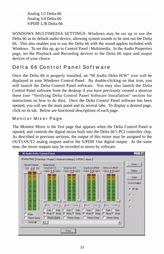
Monitor Mixer Page
The Monitor Mixer is the first page that appears when the Delta Control Panel isopened, and controls the digital mixer built into the Delta 66’s PCI controller chip.As described in previous sections, the output of this mixer may be assigned to theOUT1/OUT2 analog outputs and/or the S/PDIF Out digital output. At the sametime, the mixer outputs may be recorded in stereo by software.
13

The Monitor Mixer Page is essentially a collection of volume level faders, audiolevel (or ‘peak’) meters, and solo/mute controls. For each mixer output and inputchannel there is one of each: a volume fader, a peak meter, a solo control, and amute control.
LEVEL FADERS: Each volume fader may be controlled by dragging its fader‘handle’ vertically with the mouse, or by clicking on the ‘handle’ to make it activeand then adjusting it with the up/down cursor keys of your computer keyboard.Because the mixer has no gain, these faders only attenuate (reduce) the signallevels. The highest setting is 0dB, or ‘Unity Gain.’ The default fader setting is thequietest setting, –144dB, which essentially mutes the audio. A pair of level fadersmay be “ganged” so that both channels may be adjusted together as a stereo pair.
Also, at the top of each fader and meter is a fader level “fine adjustment” control.Clicking on the small “up” and “down” arrows will adjust the corresponding fadersetting in 0.5dB increments. Next to each fine adjustment control is a numericalfader readout that is always current and active.
PEAK METERS: Each peak meter indicates an audio signal level in “dB relative tofull-scale.” This means that a full-scale signal is referred to as “0 dB” and a signalthat is 12dB ‘quieter’ than full-scale is referred to as “-12dB.” The meters arevertically color-coded into three sections: green, yellow and red. The green sectionrepresents a safe zone, ranging from approximately -48dB to -12dB. Most audiosignals should appropriately fill this section of the meter. The yellow sectionranges from -12dB to -3dB as the signal approaches a ‘hotter’ level. For bestcapture resolution, recording in this area is both safe and advised. The red sectionof the meter ranges from -3dB to 0dB. On the input level meters, a 0dB conditionindicates overload and audio clipping may occur. Therefore be careful to adjust theincoming audio levels so that they do not peak in the red section too long (youmight use the monitoring capability of the Delta 66 to let your ears be the judge).On all output level meters, 0dB indicates full-scale output. Unlike the inputs,hardware clipping is impossible on the outputs because of the 36-bit resolution builtinto the mixer hardware. However, please note that it is possible to mix multipletracks within your software application and cause clipping to occur in the outputstream before it reaches the Delta output hardware or monitor mixer.
MASTER VOLUME: At the left side of the Monitor Mixer page, you will see the‘Master Volume’ faders and peak meters. These faders have the longest ‘throw’ andhighest meter resolution of any level controls in the mixer page. They control theoverall stereo level of the mixer output. The peak meters indicate the output signallevels with respect to full-scale and are directly affected by the settings of themaster volume faders.
MIXER INPUTS: The ‘Mixer Inputs’ are inputs to the monitor mixer. These inputsaccept hardware audio streams (directly from the Delta’s analog and digital input
14

ports) and software audio streams (digital audio generated in software to be output).This combination of streams makes the monitor mixer extremely flexible. Eachmixer input channel has its own level fader and may be panned anywhere in theleft/right stereo field. Each input also has its own peak meter. The peak metersindicate the incoming “pre-fader” levels of the incoming audio and are thereforenot affected by the fader settings. However, the input faders do affect the levels ofthe signals exiting the mixer and you will see the effect of the input faders on theoutput “Master Volume” peak meters.
Because of the large number of mixer inputs, not all inputs are displayedsimultaneously. You may use the scroll bar at the bottom of the Delta Control Panelto scroll the view left or right. From far left to right, the inputs are labeled“WavOut 1/2,” “WavOut 3/4,” then “WavOut S/PDIF.” These inputs accept thedigital audio streams being sent from your software application (or Windows) to thedriver devices with those same names. Each name begins with “WavOut” toremind you that these are software streams and may not necessarily be routed toany physical outputs (see Patchbay/Router Page). Further to the right are morechannels, labeled “H/W In S/PDIF,” “H/W In 1/2,” and “H/W In 3/4.” These mixerinputs are audio streams from the physical Delta 66 hardware inputs, hence the“H/W” at the front of each label.
PAN: Each mixer input may be individually panned anywhere in the stereo outputmix. A pan control is positioned directly under each input channel peak meter andhas the appearance of a small vertical pointer. To make a coarse adjustment, clickon the pan control with your mouse and drag it to the desired position. For fineradjustment (in 1% increments), you may click on the pan control to make it active,and then use the left/right or up/down cursor keys on your computer keyboard.Either way, while the pan setting is being adjusted, its value will appearnumerically in the Master Volume’s status box (below the Master Volume StereoGang control) as a percentage from left pan to right pan: -100% represents far left,+100% represents far right, and 0% represents the center.
SOLO: Each mixer input channel has a “Solo” checkbox associated with it.Clicking on and activating a Solo box will solo the selected channel by essentiallymuting all other signals. When more than one channel has Solo selected, all solochannels will be summed to the solo ‘buss’ (path), which is what one mightconsider an ‘in place’ solo as opposed to a PFL, or pre-fader listen (levels and pansstill apply). Deactivating all solo boxes will return all input channels to theirprevious mute/unmute states.
MUTE: Every mixer input channel has a “Mute” checkbox associated with it.Clicking on and activating the Mute box will remove that signal from the stereobuss. Deactivating the Mute box will add the signal back into the stereo buss.
STEREO GANG: All input channel pairs have a “Stereo Gang” capability.Clicking on and activating the Stereo Gang checkbox will link (or “gang”) theleft/right faders so that both channels may be adjusted together as a stereo pair.
15
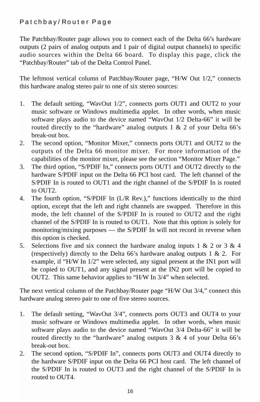
Patchbay/Router Page
The Patchbay/Router page allows you to connect each of the Delta 66’s hardwareoutputs (2 pairs of analog outputs and 1 pair of digital output channels) to specificaudio sources within the Delta 66 board. To display this page, click the“Patchbay/Router” tab of the Delta Control Panel.
The leftmost vertical column of Patchbay/Router page, “H/W Out 1/2,” connectsthis hardware analog stereo pair to one of six stereo sources:
1. The default setting, “WavOut 1/2”, connects ports OUT1 and OUT2 to yourmusic software or Windows multimedia applet. In other words, when musicsoftware plays audio to the device named “WavOut 1/2 Delta-66” it will berouted directly to the “hardware” analog outputs 1 & 2 of your Delta 66’sbreak-out box.
2. The second option, “Monitor Mixer,” connects ports OUT1 and OUT2 to theoutputs of the Delta 66 monitor mixer. For more information of thecapabilities of the monitor mixer, please see the section “Monitor Mixer Page.”
3. The third option, “S/PDIF In,” connects ports OUT1 and OUT2 directly to thehardware S/PDIF input on the Delta 66 PCI host card. The left channel of theS/PDIF In is routed to OUT1 and the right channel of the S/PDIF In is routedto OUT2.
4. The fourth option, “S/PDIF In (L/R Rev.),” functions identically to the thirdoption, except that the left and right channels are swapped. Therefore in thismode, the left channel of the S/PDIF In is routed to OUT2 and the rightchannel of the S/PDIF In is routed to OUT1. Note that this option is solely formonitoring/mixing purposes — the S/PDIF In will not record in reverse whenthis option is checked.
5. Selections five and six connect the hardware analog inputs 1 & 2 or 3 & 4(respectively) directly to the Delta 66’s hardware analog outputs 1 & 2. Forexample, if “H/W In 1/2” were selected, any signal present at the IN1 port willbe copied to OUT1, and any signal present at the IN2 port will be copied toOUT2. This same behavior applies to “H/W In 3/4” when selected.
The next vertical column of the Patchbay/Router page “H/W Out 3/4,” connect thishardware analog stereo pair to one of five stereo sources.
1. The default setting, “WavOut 3/4”, connects ports OUT3 and OUT4 to yourmusic software or Windows multimedia applet. In other words, when musicsoftware plays audio to the device named “WavOut 3/4 Delta-66” it will berouted directly to the “hardware” analog outputs 3 & 4 of your Delta 66’sbreak-out box.
2. The second option, “S/PDIF In”, connects ports OUT3 and OUT4 directly tothe hardware S/PDIF input on the Delta 66 PCI host card. The left channel ofthe S/PDIF In is routed to OUT3 and the right channel of the S/PDIF In isrouted to OUT4.
16

3. The third option, “S/PDIF In (L/R Rev.)”, functions identically to the secondoption, except that the left and right channels are swapped. Therefore in thismode, the left channel of the S/PDIF In is routed to OUT4 and the rightchannel of the S/PDIF In is routed to OUT3.
4. Options four and five connect the hardware analog inputs 1 & 2 or 3 & 4(respectively) directly to the Delta 66’s hardware analog outputs 3 & 4. Forexample, if “H/W In 1/2” were selected, any signal present at the IN1 port willbe copied to OUT3, and any signal present at the IN2 port will be copied toOUT4. This same behavior applies to “H/W In 3/4” when selected.
The rightmost vertical column of Patchbay/Router page, “H/W Out S/PDIF,”connects the Delta 66’s hardware S/PDIF output to one of six stereo sources:
1. The default setting, “WavOut S/PDIF,” connects the S/PDIF Out port to yourmusic software or Windows multimedia applet. In other words, when musicsoftware plays audio to the device named “WavOut S/PDIF Delta-66” it will berouted directly to the hardware S/PDIF output on your Delta 66’s PCI hostcard.
2. The second option, “Monitor Mixer,” connects the S/PDIF Out port to theoutputs of the Delta 66 monitor mixer. For more information on thecapabilities of the monitor mixer, please see the section “Monitor Mixer Page.”
3. The third option, “S/PDIF In,” connects the S/PDIF Out port directly to thehardware S/PDIF input on the Delta 66 PCI host card. The left channel of theS/PDIF In is routed to the left channel of S/PDIF Out and the right channel ofthe S/PDIF In is routed to the right channel of S/PDIF Out.
4. The fourth option, “S/PDIF In (L/R Rev.),” functions identically to the thirdoption, except that the left and right channels are swapped. Therefore in thismode, the left channel of the S/PDIF In is routed to the right channel of S/PDIFOut and the right channel of the S/PDIF In is routed to the left channel ofS/PDIF Out.
5. Selections five and six connect the hardware analog inputs 1 & 2 or 3 & 4(respectively) directly to the Delta 66’s S/PDIF Out port. For example, if“H/W In 1/2” were selected, any signal present at the IN1 port will be sent tothe left channel of the S/PDIF Out, and any signal present at the IN2 port willbe sent to the right channel of the S/PDIF Out. This same behavior applies to“H/W In 3/4” when selected.
At this point, you may begin to realize the versatility of the Monitor Mixer and thePatchbay/Router, and the relationship between the two. You may want to re-readthis section and make some practice adjustments within the Delta Control Panelsoftware to become proficient in routing and mixing. If somewhere in the processyou become confused, you may always restore the default settings to use the card asa straight 6-in 6-out device — just choose the topmost option in each of thePatchbay/Router columns.
17

Hardware Settings Page
The Hardware Settings page of the Delta Control Panel gives you control overmiscellaneous features of the Delta 66. To display this page, click the “HardwareSettings” tab of the Delta Control Panel.
MASTER CLOCK: This section allows you to select the source of the board’smaster clock: Internal Xtal (crystal) or S/PDIF In. Master clock operation isoutlined in the Synchronization section of this manual. Internal Xtal is the defaultsetting. Be sure to select “S/PDIF In” if you will be recording or monitoring anS/PDIF stream.
NOTE: If “S/PDIF In” is selected as the master clock source,be sure to supply a valid S/PDIF signal to the board’s activeS/PDIF input. Otherwise, erratic timing and/or impropersample rates will be experienced.
Once a master clock source has been selected, its synchronization status iscontinually monitored and displayed below the master clock radio buttons. Ifinternal crystal is selected, the status display will always say “Locked.” On theother hand, if S/PDIF In is selected as the master clock source, the control panelwill display “Locked” only when a valid S/PDIF signal is detected. It will display“Unlocked” when there is no signal at the S/PDIF input, or when the signal iscorrupt or invalid for any reason.CODEC SAMPLE RATE: This section indicates the present board sample rate, asset by application software. The sample rate displayed here is used to drive thedigital mixer and all outputs. The “Rate Locked” checkbox is used to force asample rate upon the system. It is disabled by default to allow software access toall supported sample rates. When checked, it causes the driver to only operate atthe selected sample rate. This means that any application that attempts to open theDelta 66 driver at a sample rate other than the one selected here will fail to do soand will post an error message. “Reset Rate When Idle” is selected when you wantthe sample rate to return to a particular setting when a software application is notactively using the board. This is particularly handy for keeping the digital mixerrunning at a specific sample rate.
NOTE: Because the digital monitor mixer runs at the samplerate of the rest of the board, and because sample rate directlyaffects frequency response, it may sometimes be desirable tokeep the sample rate at or above 44.1 kHz while using themonitor mixer. This is accomplished by enabling “Reset RateWhen Idle” and selecting a sample rate of 44.1 kHz or greater.
S/PDIF SAMPLE RATE: When using S/PDIF In as your master clock, this sectiontells the driver what the expected S/PDIF input sample rate is. The section is only
18

displayed when the board is set to use S/PDIF In as the master clock source. Fromthe list, select the sample rate closest to that of the S/PDIF input data. The samplerate selected here will be the only sample rate available to the softwareapplications. Therefore, you must set your audio software application to this samesample rate or else the application will display an error message.
NOTE: When S/PDIF In is the master clock source, the digitalmonitor mixer will run at the sample rate received at theS/PDIF In. Since frequency response and sample rate aredirectly related, the mixer frequency response will be directlyrelated to the sample rate of the S/PDIF input data.
MULTITRACK DRIVER DEVICES: The Delta 66 drivers may intelligentlysynchronize the beginning of recording and playback across all audio devices onthe board. When using application software that is capable of using multiplechannels simultaneously, select “Single and In-Sync” to ensure that all audiochannels will begin playback and/or recording at the same time. Otherwise select“Independent” to allow the audio channels to play independently — this settingmay be desirable if more than one application needs to access the Delta 66simultaneously.
DMA BUFFER SIZES: This section specifies the amount of system memorydedicated to digital audio buffering. Setting a buffer size that is too small mayresult in clicks or pops in the audio stream as some data may be lost. Larger bufferscause slightly more latency but prevent the pops and clicks that might occur withsmaller buffer sizes — the default settings are recommended but you may desire totweak these default settings to suit your tastes.
VARIABLE SIGNAL LEVELS: The software switches in this section allow theuser to match individual input levels and global (as in ‘all’ or ‘across the board’)output levels to the operating signal levels of the external audio equipment. Threelevel selections are available: +4dBu, ‘Consumer,’ and –10dBV. The ‘+4dBu’setting is the least ‘sensitive’ of the three settings, and ‘–10dBV’ the most sensitive.Therefore, the ‘+4dBu’ setting has the most headroom and can accept the hottestsignals of the three settings.
Consult the user guide of your external audio equipment regarding yourequipment’s line level. If for instance your audio equipment is consumer or semi-pro, and you find that its input level is a little too hot for the Delta 66’s ‘-10dBV’setting, try switching to the ‘Consumer’ setting. Conversely, if your –10dBV gearis receiving a signal from the Delta 66 that is too hot, try switching the Delta 66’soutput levels from ‘Consumer’ to the ‘–10dBV’ setting.
19

S/PDIF Page
The S/PDIF page of the Delta Control Panel configures the S/PDIF output formatand displays the status of the S/PDIF input. To display this page, click the “S/PDIF”tab of the Delta Control Panel software.
DIGITAL INPUT: This group box displays the current S/PDIF input status. TheDelta 66’s S/PDIF receiver is capable of recognizing a valid input signal versus aninvalid, corrupt or non-present one. When a valid signal is detected at S/PDIF In,this group box displays “Valid Input Detected.” When an invalid signal is detectedor no signal is present, the group box displays “Invalid or Not Present.” Below thismessage are two ‘grayed-out’ buttons: “Coax(RCA)” and “Optical.” These arefunctions of the Delta DiO 2496, another product in the M Audio Delta line, onewith both optical and coaxial S/PDIF inputs. These controls do not apply to theDelta 66.
DIGITAL OUTPUT FORMAT: Within the “Digital Output Format” group, youchoose the digital audio format of the S/PDIF output. The default setting,“Consumer,” is a true S/PDIF format and is recognized by all consumer devices.The alternate “Professional” setting is an AES/EBU type data stream, butelectrically S/PDIF. This is a work-around that is recognized by some but not allAES/EBU devices.
For both consumer and professional output formats, the “Advanced” checkbox willallow you to force a few particular status bits in the outgoing S/PDIF signal. Theadvanced option is for expert users only; however, if you decide to go exploring,change a few bit settings and get lost, you can always select the “Restore Defaults”button to restore the outgoing status bits to their factory settings. When“Consumer” and “Advanced” are both selected, the group “Consumer FormatAdvanced Settings” will appear. When “Professional” and “Advanced” are bothselected, the group “Professional Format Advanced Settings” will appear. Thesegroups are described below:
Consumer Format Advanced Settings (Copy Mode): Copy protection, also knownas Serial Copy Management System (SCMS), is written into the S/PDIF subcode, areserved part of the S/PDIF digital stream that is independent of the actual audiodata being transmitted. It can be used to inhibit the amount of copies that can bemade, or allow for unlimited copying. Three SCMS modes are available. “Original(Copy Permitted)” indicates that the source material may be copied by a receivingdevice. “1st Generation” indicates that the source material is a first generationcopy. Most devices that are capable of recording will reject material with thisSCMS mode set. The final option is “No SCMS” which may be used to overridethe other two modes and allow a recording device to successfully record the audiodata. Different manufacturers’ products may interpret these codes differently andrequire you to set these bits by “trial-and-error” until proper operation is achieved.
20

Consumer Format Advanced Settings (Emphasis): This status bit is used to indicateif pre-emphasis has been applied to the outgoing digital audio signal. The default is“None” and rarely will any user want to set the value to “50/15uSec” unless thetransmitted audio has been encoded with 50/15uSec pre-emphasis.
Professional Format Advanced Settings (Data Type): The user may assign theoutgoing data as audio or non-audio data. Many devices ignore this setting. Theobvious default is “audio.”
Professional Format Advanced Settings (Emphasis): The user may choose toindicate or not indicate if pre-emphasis has been applied to the outgoing digitalaudio signal. The default is “None” and rarely will any user want to set the value to“CCITT” or “50/15uSec” unless the transmitted audio has been encoded with oneof those types of pre-emphasis.
About Page
The “About” page, while displaying the handsome M Audio logo and applicablecopyright information, also reports the driver version and control panel softwareversion. If you have Internet browsing capabilities and are currently connected tothe Internet, clicking on the Midiman copyright will link you to the M Audio /Midiman web site.
Save, Delete, Load Buttons; H/W Installed
At the rightmost side of the Delta Control Panel are the Save, Load and Deletebuttons as well as an “installed hardware” set of radio buttons. These controlsappear regardless of what Delta Control Panel page is being displayed.
SAVE, DELETE, LOAD: The Delta Control Panel always retains the last settingsentered. However the Save, Delete, and Load functions expand this capability tostore different sets of control panel settings using different configuration file names.These configurations are then available for recall at a later date and time.
Clicking the ‘Save’ button brings up a dialog box prompting you to name thecurrent configuration. Once you have done this, click ‘OK’, and your currentconfiguration has been saved to disk. If you decide that you no longer need aparticular configuration, click the ‘Delete’ button. Highlight the name of theconfiguration file that you wish to delete, and click the ‘OK’ button. To recall orreload a saved configuration, click the ‘Load’ button. Highlight the name of theconfiguration file that you wish to recall, and click ‘OK’. Those settings will nowappear in the Delta Control Panel and the driver will automatically update thehardware.
21

H/W INSTALLED: Up to four Delta cards may be installed in a system at one time.(Note: this option may not exist in the Delta software drivers at the time of the firstrelease.) This section displays all installed Delta cards, and allows you to selectwhich particular card is under the control of the control panel software. To select acard for configuration, click the radio button to the left of that particular card in the“H/W Installed” list.
Delta 66 Recording Tutorials
In this section we will explore a few sample setups for recording and playbackusing the Delta 66 Digital Recording Interface. This is by no means an exhaustivetutorial but its intent is to help you understand most of the Delta 66’s feature set.Before beginning, you should open your music software and profile the Delta 66,enable its drivers, or otherwise setup the software for operation with the Delta 66.
NOTE: All of these examples refer to the Windows MME drivernames. If you’re using ASIO drivers, you’ll need to substitutethe appropriate driver names when referring to software inputsor outputs.
Typical Setup #1
Let’s assume for this setup that we’re recording a single guitar and vocal, thenoverdubbing another guitar and vocal track while listening to the first tracks. Thefollowing diagram shows a microphone pre-amp and direct box being used (in thiscase, the Audio Buddy™ by Midiman), and a stereo sound system. The pre-ampand direct box are required for the mic and guitar. Many instruments, such as MIDImodules or keyboards, may be connected directly to the Delta 66’s inputs.
NOTE: Because improper connections may potentially makevery loud noises, it’s a good idea to have all monitor levels setlow or muted while hooking up audio equipment — you mayeven choose to turn your computer off before making theconnections.
22

1. Plug the guitar into the channel-1 Line input of the pre-amp. Plug themicrophone into the channel-2 Mic input.
2. Plug the outputs 1 & 2 of the pre-amp into the Delta 66’s analog inputs 1 & 2.Both are balanced outputs and inputs (respectively), so use a high quality TRScable. Most balanced lines run at +4dB line level, so let’s set our+4/Consumer/-10 switches to +4dB on inputs 1 & 2. Open the Delta ControlPanel by double clicking the icon in your Windows Control Panel, and thenclick on the ‘Hardware Settings’ tab. Locate the ‘Variable Signal Levels’section. The +4 setting requires that the +4 radio button be selected.
3. Plug the hardware outputs 1 & 2 of the Delta 66 to a sound system or poweramp with speakers. If your sound system is a consumer type, set the+4/Consumer/-10 switch in the Hardware Settings page to the –10 setting. The–10 setting requires that the -10 radio button be selected, setting all of theoutputs to the –10dBV setting. Now minimize the Delta Control Panel.
4. Turn on your equipment in this suggested order: pre-amp, computer, thensound system.
We’re now physically set up to monitor, record, and play back audio. The nextsteps involve further configuring the Delta Control Panel software and also the
2 31 4
▲▲ ▲ ▲
OUTS
DELTA66 24 bit 96 khz DigitalRecording System
Break Out Box
TM
AUDIO TM
2 31 4▲▲▲▲
ins Mic
Guitar
MIDIMANAudio Buddy
Delta 66
Sound System
Computer
23

music software into which you will be recording. We’ll start with the Delta ControlPanel’s “Hardware Settings” page, then the “Patchbay/Router” page, and finally the“Monitor Mixer” page. We’re not using S/PDIF in this example so we’ll ignore theS/PDIF page.
5. Click on the Delta Control Panel on your Windows taskbar to maximize it.Click on the ‘Hardware Settings’ tab.
6. Select ‘Internal Xtal’ as the master clock source. This allows the Delta 66 toderive its sample rates from its internal clock oscillator. ‘Internal Xtal’ is thedefault setting for the Delta Control Panel, so selecting it may not be necessary(it may already be selected).
7. Under “CODEC Sample Rate,” verify that the “Rate Locked” checkbox is notactivated. This will allow your application software to set the Delta 66 samplerate as it pleases.
8. Since this example will include the use of the monitor mixer, we will activatethe “Reset Rate When Idle” feature. This will make sure the monitor mixer isrunning at a decent sample rate while the system is idle — this prevents themixer sample rate from being set too low and therefore lowering its frequencyresponse. Select a sample rate in the “CODEC Sample Rate” group to use asthis idle sample rate. Choose a 44,100 Hz or higher setting for best results, andselect the same sample rate you will be using in your application if possible.We’ve chosen 48,000 Hz for this example.
Now click on the Delta Control Panel’s “Patchbay/Router” tab. In the first columnof the Patchbay/Router page, click the radio button “Monitor Mixer” to connect themonitor mixer’s stereo output directly to Delta analog outputs OUT1 and OUT2.Now, everything that we hear at outputs 1 & 2 will reflect our settings in theMonitor Mixer page.
24
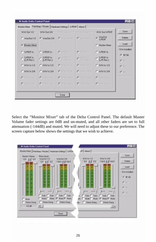
Select the “Monitor Mixer” tab of the Delta Control Panel. The default MasterVolume fader settings are 0dB and un-muted, and all other faders are set to fullattenuation (-144dB) and muted. We will need to adjust these to our preference. Thescreen capture below shows the settings that we wish to achieve.
25

9. In the Mixer Input column labeled “WavOut 1/2,” click on each fader handleand drag it up to the 0dB setting. Also, deactivate (uncheck) each WavOut 1/2mute box to unmute the channels. This will allow us, once we’ve recorded intoa music software program, to hear those software outputs upon playback.
10. Using the scroll bar at the bottom of the control panel, scroll to the right untilyou see the column labeled “H/W In 1/2.” Strum the guitar, and you shouldsee an indication in the left meter, which represents signal levels from the Deltaanalog input 1. Test the mic, and you should see an indication in the rightmeter, which represents signal levels from Delta hardware input 2.
11. Adjust the gain on the pre-amp so that you’re seeing a good level on the inputmeters, about –6dB to –3dB in the loudest parts (this is playing it a safebecause you don’t want to hit 0dB and clip). Make similar adjustments for themicrophone, using the right fader. These are the levels at which the signalswill be recorded.
12. Now let’s set the levels at which you will monitor the mic and guitar whilerecording. These are not to be confused with the levels that are recorded by thesoftware — these levels are merely monitor levels that appear in the mixeroutputs (in this case at Delta 66 analog outs 1 & 2). Click on the left faderhandle of H/W In 1/2, and drag it about halfway up. Strum the guitar. If it’snot loud enough, bring it up all of the way. If it is still not loud enough, youwill have to raise the listening level of your sound system. Make similaradjustments for the microphone, using the right fader.
13. Now fine-tune your monitor levels. Sing and play guitar, adjusting yourlistening levels using the H/W In 1/2 faders so that you have a comfortableblend of guitar and mic levels.
Now is the time to launch your music software and set it up to record and playbackaudio tracks. We’re going to speak in general terms here, since setup withinsoftware programs will vary somewhat. Minimize your Delta Control Panel so thatyou can easily access it from your Windows taskbar. Then open your musicsoftware program.
14. First set up the sample rate in the software application. This operation willdepend on the software. Choose a sample rate that is high enough to capturethe frequency response of the guitar and vocals. A general rule of thumb is tomultiply the highest frequency you would like to capture by two and addmaybe a little on top of that — that gives you a suitable sample rate. Also keepin mind that if the final results of your work will end up on a CD-ROM burnedfrom your WAV file, you probably want to use 44.1kHz, the native sample rateof “redbook” CD audio.
15. In your software application, set the ‘source’ or ‘input port’ to “Left PCM In 1/2Delta-66” on track one, and “Right PCM In 1/2 Delta-66” on track two. Armthe tracks for recording. Track one is now set up to record the guitar, and tracktwo the microphone. If your software requires this, set the software’s clocksource to ‘Audio.’
26

16. Press record on your software’s transport bar. Record a take of your guitar andvocals. Understand that while recording, you are monitoring the Delta inputsby way of the Monitor Mixer settings for H/W In 1/2, and according to theselection of ‘Monitor Mixer’ within the Patchbay/Router page. At the sametime, your software is recording from H/W In 1/2 but at the levels that were setup with the pre-amp.
17. When you are done playing, stop the recording software and rewind the take.Before playing back what you’ve recorded, you will need to assign therecorded tracks to output devices on the Delta 66.
Note: For efficiency’s sake, this step could have taken placewhile you were setting up the recording track assignments.However, since this step only affects playback and does notaffect the recording setup in any way, we’ve placed it here tolessen confusion.
Assign software track one to output device “WavOut 1/2 Delta-66” and pan thetrack (within your software) all the way to the left (hard left). Then assign track twoto output device “WavOut 1/2 Delta-66” and pan the track all the way to the right(hard right). Now, when you start playback, track one (guitar) will be sent to theDelta software (WavOut) output 1, and track two (mic) to the Delta software(WavOut) output 2. These two software outputs are inputs to the monitor mixer,therefore the recorded guitar and mic channels will be sent to the monitor mixer,levels will be modified by the mixer and the output of the mixer will be heard atanalog outputs 1 & 2.
18. Start playback from your software’s transport bar. Open the Delta ControlPanel and go to the Monitor Mixer page. Observe the meters at “WavOut 1/2”– these are the playback levels of your guitar and mic. Adjust the faders andmute controls so that you may hear the guitar and mic at the appropriate levelsand mix. These are the levels at which you may monitor the pre-recordedtracks while you overdub (record other tracks while listening to the first)additional parts.
Let’s assume that you like this take, and wish to overdub an additional guitar and aharmony vocal. We can still use hardware inputs 1 & 2 of the Delta. We’re set upto do so and there’s no reason to change these inputs. Let’s set ourselves up tooverdub these next two tracks. We will record the next two tracks of material totracks 3 & 4 of the software:
19. Back in your music program, set the ‘source’ or ‘input port’ to “Left PCM In1/2 Delta-66” on track three, and “Right PCM In 1/2 Delta-66” on track four.Arm the tracks for recording. Track three is now set up to record the guitar,and track four the microphone. Usually at this point you would want to returnto the Delta Control Panel monitor mixer to set up levels. However, because
27
you will be recording the same instruments that you did on the first two tracks,you probably won’t need to adjust input or monitoring levels.
20. Press record on your software’s transport bar. Record a take of your new guitarand vocal tracks. Because you have set up the first two tracks to play backthrough the monitor mixer, you should hear those original tracks along with theones that you are now recording.
21. When you are done playing, stop the recording software and rewind the take.Before playing back what you’ve recorded, you will need to assign the newlyrecorded tracks to output devices on the Delta 66. In your software, set theoutput ports of tracks three and four to “WavOut 3/4 Delta-66.” Pan trackthree all of the way to the left (hard left), and pan track four all of the way tothe right (hard right). Now track three (guitar) will be sent to the Deltasoftware output 3, and track four (mic) to Delta software output 4.
22. Press play on your software’s transport bar. Understand now that the fourrecorded tracks from the software are being sent to WavOut 1, WavOut 2,WavOut 3, and WavOut 4 simultaneously. Therefore they are all being input tothe monitor mixer and their playback levels can be controlled at thecorresponding channels of the monitor mixer. Open the Monitor Mixer page ofthe Delta Control Panel and adjust the levels of the four channels according toyour taste. You may also experiment with the Mute and Solo controls whilelistening to the playback. Note also that the mixer continues to monitor theguitar and mic at analog inputs 1 & 2!
At this point, you should be able to see how this multi-tracking session isdeveloping. As we add more tracks within our music software, we set them to thenext pair of Delta software outputs, and bring up the faders of those software inputsin the monitor mixer. We continually monitor from the Delta hardware outs 1 & 2,via the ‘Mon.Mixer’ setting as the monitor ‘source’ in the Patchbay/Router page,and adjusting our mix of the software outputs (and the way we monitor our guitarand vocal at the inputs) via the Monitor Mixer settings.
Notice that if we continue to overdub past track 4, we run out of WavOut devices toassign to. In this case, you may want to do some of your level mixing within thesoftware application if it supports it. Most applications will allow you to assignmore than one track to an output device and then set the relative levels of the trackswithin the software, letting the software do the mixing. In this example you couldhave assigned all of the playback tracks to “WavOut 1/2” and let the softwarehandle the mix.
Typical Setup #2
This section contains a multi-tracking example illustrating another way to use theDelta 66 and its control panel software. We’re going to use multiple inputs andmultiple outputs, so a mixing console that will handle multiple inputs must be usedon the output side of the Delta 66. A discussion of mixing consoles and their usewill follow in Appendix B. For simplicity in this example we’ll use pre-amps to get
28

the signal to the Delta 66, and a mixer connected to a sound system to handle themultiple outputs.
Let’s say that we’re recording a guitar/vocal duo. We’ve got a mic on each voice,with the guitars going ‘direct’ into the pre-amps.
NOTE: Because improper connections can potentially makevery loud noises, it’s a good idea to have monitor levels downwhile hooking up audio equipment — you may choose to turnyour computer off before making the connections.
2 31 4
▲▲ ▲ ▲
OUTS
DELTA66 24 bit 96 khz DigitalRecording System
Break Out Box
TM
AUDIO TM
2 31 4▲▲▲▲
ins
MicsGuitars
MIDIMANAudio Buddy
Delta 66
Computer
Mixer
MIDIMANAudio Buddy
29
1. Plug the microphones into the mic inputs 1 & 2 of the pre-amps. Plug theguitars into the high impedance inputs 3 & 4 of the pre-amps.
2. Plug the outputs of the pre-amps 1-4 into the hardware inputs 1-4 of the Delta66. Usually pre-amp outputs are balanced, so if they are, use TRS cables andset the Delta +4/Consumer/-10 input switches to the +4dB setting in theHardware Settings page of the Delta Control Panel.
3. Plug the hardware outputs 1-4 of the Delta 66 into your mixer’s inputs 1-4(using 1-4 is recommended for convenience, but not necessary). Some mixersrun at -10 line level, and some at +4. Many mixers may be set either way andactually have their own +4/-10 switch(es). Let’s assume that our mixer runs at+4, so set the Delta +4/Consumer/-10 output switch to +4 in the control panel.At this point we’ll assume that all mixer faders are down.
We’re now physically set up to monitor, record, and playback audio with theDelta 66 and related components. The next steps involve the settings in the DeltaControl Panel. We’ll use the same settings as Typical Setup #1 for the DeltaControl Panel’s ‘Hardware Settings’ page, i.e. “Internal Xtal”, “Reset Rate WhenIdle” and 48kHz idle sampling rate. The settings that we’ll focus on will involvethe ‘Patchbay/Router’ page. We won’t be using the Delta 66’s Monitor Mixer, sowe’ll ignore the ‘Monitor Mixer’ page.
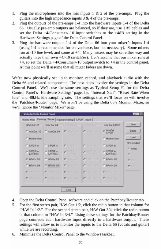
4. Open the Delta Control Panel software and click on the Patchbay/Router tab.5. For the first stereo pair, H/W Out 1/2, click the radio button in that column for
“H/W In 1/2.” For the second stereo pair, H/W Out 3/4, click the radio buttonin that column to “H/W In 3/4.” Using these settings for the Patchbay/Routerpage connects each hardware input directly to a hardware output. Thesesettings will allow us to monitor the inputs to the Delta 66 (vocals and guitar)while we are recording.
6. Minimize the Delta Control Panel to the Windows taskbar.
30

7. Open your music software program. Set up four tracks for recording:
Track one — Left PCM In 1/2 Delta-66 Track two — Right PCM In 1/2 Delta-66Track three — Left PCM In 3/4 Delta-66 Track four — Right PCM In 3/4 Delta-66
8. Now we want to set up the output ports for the four tracks.
Track one — WavOut 1/2 Delta-66, panned hard left. Track two — WavOut 1/2 Delta-66, panned hard right. Track three — WavOut 3/4 Delta-66, panned hard left. Track four — WavOut 3/4 Delta-66, panned hard right.
9. Bring up the meter view in your music software, and let’s start to get somelevels here. Let’s say that your hardware input 1 is the lead vocal mic. Havethe lead vocalist test the mic while raising the input gain on your pre-ampchannel 1 until you see a level of –6dB or so. This is your recording level. Atthe same time you can begin to raise the faders on your mixer until you hearthe voice at a comfortable volume. This is your monitor level. Do the samefor the other vocal mic, and each guitar.
NOTE: You could view the record levels from the Monitor Mixerpage also. The levels appearing in H/W In 1/2 and H/W In 3/4will represent the signal appearing at the hardware inputs. Weare not monitoring via the Monitor Mixer in this example,however, so no faders in this page are needed or apply.
Once this is done, we are set up and ready to record. Close or minimize yoursoftware’s meter view at this point.
10. Arm tracks one through four for recording and press the record button on yourmusic software’s transport bar.
11. Once you have a take that you think is worth listening to, stop recording andrewind. Maximize the Delta Control Panel from your Windows taskbar.
12. Click the Patchbay/Router tab. In the first column, H/W Out 1/2, click theradio button “WavOut 1/2” so that our monitoring source is now the softwareoutputs from the music program. Set the H/W Out 3/4 column to “WavOut3/4.” Now all of the software outputs of the music program are connected tothe corresponding hardware outputs. Minimize the control panel.
13. Click play on the transport bar of your music software. If the take issatisfactory, disarm tracks one through four and revel in your success. If youwish to redo the tracks, “undo” the recording in your software, repeat steps 10through 13 in this section.
31

Using the Delta 66 and the Delta Control Panel software in this manner may beyour choice when using a mixing console to control the monitor and playbacklevels. If this were a real recording situation and you wished to add otherinstruments as overdubs, you might want to combine recorded tracks to one stereopair of outputs (WavOut 1/2 Delta-66, for example). This would ‘free up’ severalchannels for monitoring the overdubs.
Typical Setup #3
Let’s look at a setup that involves a typical transfer of information from DAT tocomputer and back to DAT. Here, we’ll be using the Delta 66’s S/PDIF I/O plusone of the analog output stereo pairs.
NOTE: Because improper connections can potentially makevery loud noises, it’s a good idea to have monitor levels downwhile hooking up audio equipment — you may even choose toturn your computer off before making the connections.
In this example, we will connect a DAT to the Delta 66 PCI host card using coaxialS/PDIF cables (75-ohm impedance RCA-to-RCA). We’ll also connect theDelta 66’s analog outputs to a sound system for monitoring purposes. A setup likethis might be used to transfer a number of mixes from a DAT into an audio editingprogram, performing the appropriate edits, and then transferring the edited materialback to DAT.
The example below may at first look long and laborious, but you will find that mostof the settings are factory defaults and will rarely need to be modified.
32

Transferring from DAT to Delta 66
1. Connect the DAT’s coaxial S/PDIF output to the S/PDIF In of the Delta 66 PCIhost card, using a good quality cable.
2. Connect the Delta 66 analog outputs 1 & 2 to some type of amplified soundsystem. The sound system should be equipped with speakers or headphones.Set the software +4/Consumer/-10 switch on the Delta Outputs to becompatible with that sound system’s inputs.
3. Because you will be recording from the S/PDIF input, you will need to set upthe Delta 66 to synchronize its master clock with the S/PDIF input. To do this,open the Hardware Settings page of the control panel software. Under MasterClock, select “S/PDIF In.”
4. Next, you will need to tell your application software the expected sample rate.We’ll use 44.1 kHz in this example. Therefore, on the Hardware Settings page,set the “S/PDIF Sample Rate” to 44,100.
2 31 4
▲▲ ▲ ▲
OUTS
DELTA66 24 bit 96 khz DigitalRecording System
Break Out Box
TM
AUDIO TM
2 31 4▲▲▲▲
ins
Sound System
6 PCI Computer
DAT
Delta 66Break Out Box
33

5. In order to monitor the digital signal coming into the Delta 66, switch to thePatchbay/Router page of the control panel software. In the “H/W Out 1/2”column, select the radio button labeled “S/PDIF In.” This will copy all S/PDIFinput audio directly over to the analog outputs. Therefore, in this example, themonitor mixer will be completely bypassed. Once this assignment is made,you may play the DAT material at any time and verify that it is making it intothe Delta 66 successfully. This can be done regardless of whether or not yourrecording software is open.
34

6. Within your recording software, select “S/PDIF In Delta-66,” as the audioinput device. The Delta input appears as a stereo pair.
7. Start your software recording and then start your DAT material playing. Youshould be able to hear the DAT material through your sound system.
Transferring from Delta 66 to DAT, monitoring with DAT
1. Connect the Delta 66’s S/PDIF Out to the DAT’s coaxial S/PDIF Input using agood quality cable.
2. Connect the DAT analog outputs to some type of amplified sound system. Thesound system should be equipped with speakers or headphones.
3. Because you will be playing back at the recorded sample rate, you will want toset the Delta 66’s master clock to use the Delta 66’s internal crystal. Do this byopening the Hardware Settings page of the Delta Control Panel software andunder Master Clock, selecting “Internal Xtal.” Also, under the Codec SampleRate section you may uncheck “Rate Locked” if it is previously checked. Thisallows for more flexible sample rate playback.
4. In order to verify proper S/PDIF Output routing, open the Patchbay/Routerpage of the control panel software. In the “H/W Out S/PDIF” column, selectthe radio button named “WavOut S/PDIF.” Now everything that is sent byyour software to the “WavOut S/PDIF” device will be routed to the hardwareS/PDIF output, and consequently to the DAT.
5. Next let’s make sure the S/PDIF output format is correct. Open the S/PDIFpage of the control panel software. Under Digital Output Format, choose“Consumer.” Uncheck “Advanced” if it is checked previously. Now click onthe “Restore Defaults” button to set the default S/PDIF outgoing status bits.This will disable copy protection and also set the emphasis to “none,” allowingthe DAT to accept and record the audio properly.
6. Within your recording software, select “WavOut S/PDIF Delta-66” as the audiooutput device.
7. Start your DAT recording and then start your software playing. You should beable to hear the DAT material through your sound system. This verifies thatthe digital audio is making it into the DAT correctly.
Sound System
Delta 66 PCI Card in Computer
DAT
To Break Out Box
35
Troubleshooting
This section addresses potential problems that can occur in all operating systemenvironments, with emphasis on hardware troubleshooting. Within the PCenvironment there are a limited number of hardware resources (I/O addresses,IRQs, and DMA channels) available for use. Since audio cards require manyresources, most audio card installation problems arise from unavailable orimproperly set resources. This is important enough to repeat:
IMPORTANT: Most sound card installation problems resultfrom attempting to use system resources (IRQs, addresslocations) already in use by other hardware (or software actingas “virtual” hardware) in the system.
The Delta 66 has been carefully designed to minimize the number of resourcesconsumed (it requires just one IRQ and does not require any DMA channelresources). It is also capable of sharing an IRQ in some cases. However, thepossibility of resource conflicts still exists due to the nature of the Windowsenvironment. Many resource conflicts are automatically recognized by Windows’Plug-and-Play (PnP) system. When a resource conflict is detected, it is displayed inthe Windows Device Manager. The Device Manager places a yellow exclamationpoint on top of the icon associated with the problem device. For an example ofhow the Device Manager should look when a Delta 66 is successfully installed, seethe “Verifying Windows Driver Installation” section of this manual. If a yellowexclamation point does appear over your Delta 66 icon, you may have a resourceconflict. There are several ways to approach this problem.
NOTE: When resolving conflicts between PnP and non-PnPdevices, it is recommended to re-adjust the resource settingsof the non-PnP device first. Typically, Windows is only awareof the resource settings of the installed PnP devices and hasno information available to it for adjusting the PnP devices’resources around those of the non-PnP devices. Theexceptions to this are when: (1) a non-PnP device has a trueWindows 95/98 driver written for it, (2) the BIOS setup allowsreserving an IRQ for a legacy device as opposed to a PnPdevice, or (3) resource requirements for the non-PnP devicehave been manually entered into the Windows DeviceManager. In these cases Windows is aware of the non-PnPdevice’s resource requirements.
One of the quickest ways to change the resources assigned to a PCI card like theDelta 66 is to merely relocate the card to another PCI slot. With the computer’spower off, remove the Delta 66 from its current PCI slot, move it to anotheravailable PCI slot, and turn your computer back on. More often than not, this will
36
change the IRQ assignment of the Delta 66 when you re-enter Windows. Afterreturning to Windows, follow the steps outlined in the “Verifying Windows DriverInstallation” section of this manual. It might take more than one PCI slot relocationto find an open IRQ.
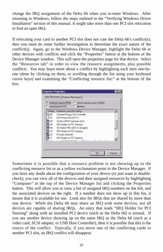
If relocating your card to another PCI slot does not cure the Delta 66’s conflict(s),then you must do some further investigation to determine the exact nature of theconflict(s). Again, go to the Windows Device Manager, highlight the Delta 66 orother devices with conflicts and click the “Properties” button at the bottom of theDevice Manager window. This will open the properties page for that device. Selectthe “Resources tab” in order to view the resource assignments, plus possibleconflicts. You may learn more about a conflict by highlighting each item one-by-one (done by clicking on them, or scrolling through the list using your keyboardcursor keys) and examining the “Conflicting resource list:” at the bottom of thebox.
Sometimes it is possible that a resource problem is not showing up in theconflicting resource list or as a yellow exclamation point in the Device Manager. Ifyou have any doubt about the configuration of your device (or just want to double-check), you can view all of the devices and their assigned resources by highlighting“Computer” at the top of the Device Manager list and clicking the Propertiesbutton. This will allow you to view a list of assigned IRQ numbers on the left, andthe associated devices on the right. If a number does not show up in this list, itmeans that it is available for use. Look also for IRQs that are shared by more thanone device. While the Delta 66 may share an IRQ with some devices, not alldevices are capable of sharing IRQs. An entry that reads “IRQ Holder for PCISteering” along with an installed PCI device (such as the Delta 66) is normal. Ifyou see another device showing up on the same IRQ as the Delta 66 (such as avideo card, SCSI adapter, or USB Host Controller), then it is possible that this is thesource of the conflict. Typically, if you move one of the conflicting cards toanother PCI slot, an IRQ conflict will disappear.
37

Address conflicts are rare amongst PCI devices, but if there is no obvious IRQconflict, why not check for I/O Address conflicts while in the Device Manager?You may view the list of assigned I/O addresses by selecting the “Input/output(I/O)” radio button below the “Interrupt Request (IRQ)” radio button at the top ofthe Device Manager page. I/O addresses are displayed as 16-bit hexadecimalnumbers, therefore one might note that an address of 300h (the default address ofthe Winman 4X4/s, for instance), will read “0300” in this list.
If scanning all the resource lists in the Device Manager does not provide an answeror clue to the resource conflict, you might want to exit Windows and do a finalinspection of your computer’s BIOS setup. Some newer BIOS’s (see yourcomputer manual) allow the reservation of an IRQ for each PCI slot on themotherboard. This may be very handy in resolving IRQ assignments for PCIdevices.
Also, sometimes a BIOS is configured to direct a particular IRQ to an ISA legacydevice (non-PnP ISA card), and needs to be told to look for a PCI/ISA PnP device(some systems default to this, especially with IRQs 3 and 4). Consult yourcomputer or motherboard manual for advice on how to do this.
Finally, with some systems you will reach the dead-end realization that you have noavailable IRQ’s — every one of them is assigned to some device in the system.This most typically occurs with pre-packaged computers made by the big-nameO.E.M. computer companies. These computers have so many features packed intothem that every IRQ is consumed. In this type of situation, some kind ofreconfiguring or reprioritizing your system is in order. Optionally, Windows mayallow you to create a second “hardware configuration” which disables some of theinstalled devices and makes their resources available for general use. See yourWindows documentation for information on this subject.
38
Troubleshooting Tips for Frequently AskedQuestions
Problem: No Sound.Possible Cause 1: The Delta 66 hardware or software device drivers arenot properly installed. See the installation sections of this manual for furtherinformation.Possible Cause 2: There is a resource conflict between the Delta 66 andanother device in your computer. Check the Delta 66 configuration (Address, IRQ)against those of the other installed devices. If necessary, change the settings for theone or more of the devices.Possible Cause 3: Your application software has not been properlyconfigured to use the Delta 66 as its audio output device.Possible Cause 4: Misrouted outputs in the Delta Control Panel. Check theDelta Control Panel’s Patchbay/Router page to verify output routing assignments.Also, make sure that if the output is routed from the digital mixer, that the mixer’sfaders, solo and mute controls are set up properly.Possible Cause 5: Improper connections of the audio accessories. Verifythat the Delta 66 analog audio outputs are properly connected to a digital mix deckor external mixer/amplifier, or the S/PDIF Out is connected to an external digitalaudio device capable of receiving S/PDIF.
Problem: No visual activity on Audio Input volume (VU) meters of usersoftware.Possible Cause 1: The Delta 66 input devices are not properly selected inthe user’s application software.Possible Cause 2: If the software is recording from the Delta 66’s monitormixer device, be sure that the mixer’s faders, solo and mute controls are set upproperly.Possible Cause 3: Improper connections to audio accessories.
Problem: Repetitious Sound.Possible Cause: An IRQ resource conflict. Often this will result in a smallsegment of sound (0.5 to 1 second) repeating itself over and over, sometimescompletely locking up the computer. See the general troubleshooting suggestionsat the beginning of this section.
Problem: I’m getting some pops and clicks in my audio recording.Possible Cause 1: Input levels are too “hot,” causing clipping or inputdistortion. Make sure you have the proper signal levels set in the Delta ControlPanel software. “+4” can handle much hotter signals than “Consumer” or “-10.” Ifyou find that you are still clipping at the +4 setting, you will need to turn down theaudio at the source.
39
Possible Cause 2: If you are recording from the S/PDIF input, but youhave the Delta 66’s master clock set to something other than the S/PDIF input, youare recording an out-of-sync S/PDIF stream. This can result in lost or bogussamples being recorded.Possible Cause 3: Your application software may not have the proper audiobuffer sizes set. Each software application handles this differently, but typicallythere is somewhere in the software’s setup to set the size of the playback andrecording buffers used by the application. Some applications also require you torun a card calibration (sometimes called “profiling”) the first time you use thesoftware with a new audio card.Possible Cause 4: Some accelerated graphics cards use excessive amountsof system bandwidth, preventing the recording buffer of an audio card fromkeeping up with demand. This can cause clicks in the recording. Reducing orturning off the graphics card’s graphics acceleration feature often resolves thisproblem. In Windows, the level of graphics acceleration is accessed from Start|Settings | Control Panel | System | Performance | Graphics.
Problem: I’m getting some pops and clicks in my monitoring signal, evenwhen my system is idle.Possible Cause: If the S/PDIF input is not muted in the monitor mixer, andyou have the Delta 66’s master clock set to something other than the S/PDIF input,you are monitoring an out-of-sync S/PDIF stream. This can result in lost or bogussamples being monitored and recorded.
Problem: The sound from the monitor mixer is muffled. It sounds as if it wererunning through a mixer with the treble control turned all the way down!Possible Cause: The current Delta 66 sample rate is too low. The monitormixer is a digital device that runs at the current sample rate of the Delta 66 board.The frequency response of the mixer is roughly one-half of the sample rate. Thereis no way to prevent this lost frequency response while playing back or recording ata low sample rate. However, it may be prevented when the system is idle. See the“CODEC SAMPLE RATE” paragraph of the section ‘Hardware Settings Page’ formore information.
40
Appendix A - Technical Specs
Analog AudioPeak Analog Input Signal: +14dBu (+4dBu setting),
+6dBV (Consumer setting),0dBV (-10dBV setting).
Peak Analog Output Signal: +14dBu (+4dBu setting), +6dBV (Consumer setting).0dBV (-10dBV setting)
Dynamic Range:Outputs: 103dB (a-weighted),Inputs: 99dB (a-weighted)
THD (at 0dBFS):Outputs: less than 0.0015%,Inputs: less than 0.0024%
Frequency Response: 22Hz - 22kHz, -0.3,-0.2dBInput Impedance: 10k ohms minimumInput Connectors: 1/4” female TRS-type, balanced or unbalancedOutput Connectors: 1/4” female TRS-type, balanced or unbalanced
Digital AudioDigital Input Format: S/PDIF coaxial, 0.5V to 5V peak-to-peak.Digital Input Sample Rate: 8kHz to 96kHz.Digital Output Format: S/PDIF coaxial, 0.5V peak-to-peak;
AES/EBU data stream over S/PDIF coaxial.Digital Output Sample Rate: 8kHz to 96kHz.
Adapter Resource RequirementsIRQ: One requiredI/O Addresses: Four blocks: 32, 16, 16, and 64 bytesDMA Channels: None required
41

Appendix B -If You Use An External Mixer...
Our main objective is to get the signal we want to record to the Delta 66, and tomonitor the outputs from the Delta 66. The Delta 66 has a mixer contained in itsPCI chip that allows you to mix hardware inputs and software outputs and send it toan analog stereo output pair and/or the S/PDIF out. The Delta 66 also allows you torecord that mix into your music software as a hardware input. Still, some of youmay choose to use a mixing console to achieve your multi-tracking goals.
A mixing console (sometimes referred to as mixing ‘board’ or ‘desk’) that isdesigned for multi-track recording has the ability to fulfill these two basic functions— getting the signal to the recording device, and receiving the outputs of thatrecording device for mixing or monitoring. In this sense, a recording console istwo mixers in one. A mixer designed for recording will also have the ability to sendto one or more mixdown decks, to monitor these mixdown decks, to controlseparate control room and studio listening levels, as well as other recording-specificfunctions.
There are two basic layouts for the recording console, “split section” and “in-line.”The split section design is arranged with a recording or ‘channel’ section (to sendthe signal to the recording device) side-by-side with a monitoring section (toreceive the outputs of the recording device). The in-line design has the recordingand monitoring sections “in line” within each channel module, so that each channelhas two line inputs.
The recording section is distinguished by its bussing system, which takes therecording channel signal through a summing matrix to multiple outputs- usually inmultiples of eight. It could be said that an ‘8-buss system’ is designed for 8 trackrecording, and a 24-buss system for 24 track recording, etc., but this is not writtenin stone.
What we are describing here is the extreme- a professional, costly piece of gear thathas been purchased for this one specialized purpose. There are features inherent inother types of consoles, however, that will allow us to perform these two separatefunctions of recording and monitoring. A sound reinforcement or a broadcastconsole, and in some cases a recording console, might offer a bussing system in theform of “sub-mix outs.” These are usually arranged in stereo pairs with a set oflevel control faders for each pair. This configuration can be effectively used forrecording, as long as the record channels are taken out of the stereo buss. Thedifference here is that there is no real distinction between the recording andmonitoring sections.
42
Some line mixers have a number of effect or auxiliary sends for each channel.These sends will have their own individual level control and will receive the signaleither pre fader or post fader, i.e. either independent or dependent on that channel’sfader level. It is possible to use these “aux sends” to send a signal to the recordingdevice. A pre fader send is certainly preferable, since this will allow for a recordinglevel that is separate from the monitoring level.
The bottom line here is that you can not use the ‘main output’ of your mixer to senda signal to the recording device, and then take the outputs of that recording deviceback into the mixer (whose signal also goes to the main out). This creates afeedback loop, bad for your eardrums and bad for your equipment.
One modern console design gets around that by offering an “alt out,” which is analternate stereo buss or output. When selecting ‘alt out’ on a channel, it mutes thatchannel to the stereo buss and redirects it to the alt out buss. This could be viewedas a 2-buss system, and can be used effectively for recording purposes.
In our Typical Setup 1 and 2 in the previous section, we used pre-amps to handlethe recording. A line mixer that simply received the line outputs from the 66 andmixed them to stereo could handle the monitoring needs. Hopefully, theinformation here will give you some insight into how to use the gear that you own,or what to look for if you are seeking additional equipment to facilitate your harddisk recording.
43
Limited Lifetime Warranty
MIDIMAN warrants that this product is free of defects in materials andworkmanship under normal use so long as the product is: owned by the originalpurchaser; the original purchaser has proof of purchase from an authorizedMIDIMAN dealer; and the purchaser has registered his/her ownership of theproduct by sending in the completed warranty card.
This warranty explicitly excludes power supplies and included cables which maybecome defective as a result of normal wear and tear.
In the event that MIDIMAN receives written notice of defects in materials orworkmanship from such an original purchaser, MIDIMAN will either replace theproduct, repair the product, or refund the purchase price at its option. In the eventany repair is required, shipment to and from MIDIMAN and a nominal handlingcharge shall be born by the purchaser. In the event that repair is required, a ReturnAuthorization number must be obtained from MIDIMAN. After this number isobtained, the unit should be shipped back to MIDIMAN in a protective packagewith a description of the problem and the Return Authorization clearly written onthe package.
In the event that MIDIMAN determines that the product requires repair because ofuser misuse or regular wear, it will assess a fair repair or replacement fee. Thecustomer will have the option to pay this fee and have the unit repaired andreturned, or not pay this fee and have the unit returned unrepaired.
The remedy for breach of this limited warranty shall not include any otherdamages. MIDIMAN will not be liable for consequential, special, indirect, orsimilar damages or claims including loss of profit or any other commercial damage,even if its agents have been advised of the possibility of such damages, and in noevent will MIDIMAN’s liability for any damages to the purchaser or any otherperson exceed the price paid for the product, regardless of any form of the claim.MIDIMAN specifically disclaims all other warranties, expressed or implied.Specifically, MIDIMAN makes no warranty that the product is fit for any particularpurpose.
This warranty shall be construed, interpreted, and governed by the laws of the stateof California. If any provision of this warranty is found void, invalid orunenforceable, it will not affect the validity of the balance of the warranty, whichshall remain valid and enforceable according to its terms. In the event any remedyhereunder is determined to have failed of its essential purpose, all limitations ofliability and exclusion of damages set forth herein shall remain in full force andeffect.
44