Embed Size (px)
Citation preview

Table of contents
1. WARNINGS AND LEGAL INFORMATION ........................................................................... 3
3.5 LEGAL INFORMATION AND RESPONSIBILITY .......................................................................... 3 3.6 ELECTROSTATIC DISCHARGE AWARENESS .......................................................................... 3 3.7 SAFETY ISSUES ................................................................................................................. 3 3.8 DISCLAIMER ...................................................................................................................... 3 3.9 DEFINITIONS ..................................................................................................................... 3
2. APPLICATION – GAS ENGINE AND CHP CONTROL ........................................................ 4
2.1 FUNCTIONALITIES .............................................................................................................. 5 2.2 SCOPE OF SUPPLY ............................................................................................................ 6 2.3 NEEDED INFORMATION FOR QUOTATIONS ............................................................................ 6
3. SOLUTION DESCRIPTION, ENGINE ................................................................................... 7
3.1 DM 400 GAS – MAIN CONTROLLER ..................................................................................... 8 3.2 AIR/FUEL MIXERS ............................................................................................................... 9 3.3 THROTTLE VALVE AND ACTUATOR ....................................................................................... 9 3.4 DIGITAL IGNITION CONTROL SYSTEM ................................................................................. 10 3.5 ANTI KNOCKING SYSTEM .................................................................................................. 11
4. SOLUTION DESCRIPTION, RETROFITS .......................................................................... 12
5. SOLUTION DESCRIPTION, CHP ....................................................................................... 13
5.1 AVAILABLE COMBINED CONTROLS ..................................................................................... 13 5.2 USER INTERFACE ............................................................................................................ 14
APPLICATION NOTES
Document no.: 4189341154A SW version 4.6x.x or later
• Solution descriptions • Functional descriptions
Delomatic 400 (DM 400) based Gas Engine and Combined Heat and Power (CHP)
Control and Management System
DELOMATIC 400 GAS APPLICATION NOTES

Delomatic 400 Gas Application notes, gas engines and CHP
DEIF A/S Page 2 of 14
TABLE OF CONTENTS
1. WARNINGS AND LEGAL INFORMATION ........................................................................... 3
LEGAL INFORMATION AND RESPONSIBILITY ..................................................................................... 3 ELECTROSTATIC DISCHARGE AWARENESS ..................................................................................... 3 SAFETY ISSUES ............................................................................................................................ 3 DISCLAIMER ................................................................................................................................. 3 DEFINITIONS ................................................................................................................................ 3
2. APPLICATION – GAS ENGINE AND CHP CONTROL ........................................................ 4
2.1 FUNCTIONALITIES .............................................................................................................. 5 2.2 SCOPE OF SUPPLY ............................................................................................................ 6 2.3 NEEDED INFORMATION FOR QUOTATIONS ............................................................................ 6
3. SOLUTION DESCRIPTION, ENGINE ................................................................................... 7
3.1 DM 400 GAS – MAIN CONTROLLER ..................................................................................... 8 3.2 AIR/FUEL MIXERS ............................................................................................................... 9 3.3 THROTTLE VALVE AND ACTUATOR ....................................................................................... 9 3.4 DIGITAL IGNITION CONTROL SYSTEM ................................................................................. 10 3.5 ANTI KNOCKING SYSTEM .................................................................................................. 11
4. SOLUTION DESCRIPTION, RETROFITS .......................................................................... 12
5. SOLUTION DESCRIPTION, CHP ....................................................................................... 13
5.1 AVAILABLE COMBINED CONTROLS ..................................................................................... 13 5.2 USER INTERFACE ............................................................................................................ 14

Delomatic 400 Gas Application notes, gas engines and CHP
DEIF A/S Page 3 of 14
1. Warnings and legal information This chapter includes important information about general legal issues relevant in the handling of DEIF products. Furthermore, some overall safety precautions will be introduced and recommended. Finally, the highlighted notes and warnings, which will be used throughout this handbook, are presented.
Legal information and responsibility DEIF takes no responsibility for installation or operation of the generator set. If there is any doubt about how to install or operate the generator set controlled by the unit, the company responsible for the installation or the operation of the set must be contacted.
Electrostatic discharge awareness Sufficient care must be taken to protect the terminals against static discharges during the installation. Once the unit is installed and connected, these precautions are no longer necessary.
Safety issues Installing the unit implies work with dangerous currents and voltages. Therefore, the installation should only be carried out by authorised personnel who understand the risks involved in working with live electrical equipment.
Disclaimer DEIF A/S reserves the right to change any of the contents of this document without prior notice. The English version of this document always contains the most recent and up-to-date information about the product. DEIF does not take responsibility for the accuracy of translations, and translations might not be updated at the same time as the English document. If there is a discrepancy, the English version prevails.
Definitions Throughout this document, a number of notes and warnings will be presented. To ensure that these are noticed, they will be highlighted in order to separate them from the general text. Notes Warnings
The notes provide general information which will be helpful for the reader to bear in mind.
The warnings indicate a potentially dangerous situation which could result in death, personal injury or damaged equipment, if certain guidelines are not followed.
Be aware of the hazardous live currents and voltages. Do not touch any AC measurement inputs as this could lead to injury or death.
The units are not to be opened by unauthorised personnel. If opened anyway, the warranty will be lost.

Delomatic 400 Gas Application notes, gas engines and CHP
DEIF A/S Page 4 of 14
2. Application – Gas Engine and CHP Control This document describes the functionalities and application of gas engine solution offered by DEIF to meet the requirements for a gas engine driven generator. The solution offered is a comprehensive and single supplier solution designed to control and operate your gas engine-based power plant or Combined Heat and Power plant (CHP) efficiently. A unique combination of flexibility and expansion possibilities of the DEIF Delomatic 400 (DM 400) gas engine control solution makes it a perfect fit for new-build applications requiring coordinated development with engine manufacturers, as well as for control system upgrade where reverse engineering and adaptation with existing systems is required. DEIF has experienced application and designing engineers who will help in both applications for selecting and designing the right solution.
Fig. 1: DEIF Fully integrated gas engine and CHP control system
Delomatic 400 Gas Application notes, gas engines and CHP
DEIF A/S Page 5 of 14
The DEIF control system has future-proof communication facility to enable the remote operation and monitoring of your power plant. In total, DEIF brings to you an advanced and state-of-the-art control system which can meet your present and future plant requirements.
2.1 Functionalities The DEIF gas engine solution will take care of the following functionalities:
• Speed and load control by o Throttle valve control o Integrated speed governor o Turbo bypass control o Load reduction functions
• Air/fuel mix control o Lambda control o p/T control o Combustion chamber temperature control
• Auto synchronisation • Generator controls
o Frequency control o Active power control o Reactive power control
• Generator protection – see the list of protections in the data sheet • Mains failure protection – see the list of protections in the data sheet • Monitoring and supervision including, but not limited to:
o Lube oil pressure o Coolant temperature o Pressure and temperature of the gas line o Gas leak check o Exhaust temperature after turbocharger o Exhaust back pressure supervision. o Water level monitoring for coolant, emergency cooler, and heating circuit o Run time of air flaps o Run time of exhaust bypass o Tooth-on-tooth supervision of the starter o Level supervision in external lube-oil tanks (fresh oil min, waste oil max)
• Fully automated gas engine start/stop (local or remote) • Control of engine cooling circuit, emergency cooling circuit • Control of heating circuit (CHP) • Control of exhaust turbo bypass/waste gate • Control of room temperature • Control of air flap • Engine standstill heating • Idle speed heating up control • Post run of the engine • Mode of operation
o Peak shaving o Island operation o Load sharing o Parallel to grid operation o Heat-controlled operation (heat demand-controlled power output) o CH4-value-controlled operation o Gas level- or gas pressure-controlled operation
• Demand signal to a compressor • Second gas type selectable • Modbus read/write (TCP/IP)
Delomatic 400 Gas Application notes, gas engines and CHP
DEIF A/S Page 6 of 14
2.2 Scope of Supply The scope of supply includes the following
• DM 400 Controller • HMI • Throttle driver • Mixer driver • AVR driver
Optional:
• Throttle valve • Actuator/torque motor with
o Cable harness o Adapter flanges and external levers
• Gas mixer • Passive speed sensor with cable (crankshaft) • Intake manifold pressure sensor with cable • Intake manifold temperature sensor with cable • Ignition controller with
o Cable harness o Ignition coils with adapter and high-tension leads o Ignition rail o Inductive trigger sensor with cable (camshaft) o Trigger disc for camshaft
• AKR 3 Anti-knocking regulator with o Cable harness (power supply and CAN bus) o Knocking sensors o Cable harness for knocking sensors
• DVC 310 AVR o Up to 6 A excitation output o PMG or shunt AC supply
2.3 Needed information for quotations The preparation of the gas engine control system solution requires the details about the site and engine to prepare a techno-commercial offer. As a minimum, the following details are needed:
• Make and model of engine • Generator technical data • AVR make and model • Operation philosophy • P&I diagram for heating and cooling circuits • Gas composition
If it is a retrofit project, in addition to the above:
• Existing control system details o Make and model of ignition system o Make and model of throttle valve o Make and model of turbo bypass (if fitted) o Make and model of gas mixer/gas control valve o Make and model of anti-knocking system (if fitted)
You need to collect as many details as available for the existing engine including but not limited to the above-mentioned.

Delomatic 400 Gas Application notes, gas engines and CHP
DEIF A/S Page 7 of 14
3. Solution description, engine This section gives a brief overview of the architecture and functional principle of the gas engine control system. The DEIF gas engine control system consists of a DM 400 Gas as main integrated controller for a gas engine and generator. The DM 400 controller senses, controls and takes feedback from other critical systems like ignition systems, anti-knocking systems and so on to provide a safe and reliable control system for your engine. The entire system can include mechanical items like air-fuel mixer and throttle and so on to reduce the commissioning time and prevent coordination hassles from multiple suppliers. A basic installation looks like this: 12” touch screen
Fig. 2
Anti-knocking Throttle with Ignition system with rail, pickup gas mixer manifold system driver and camshaft trigger wheel pressure/ temperature
Delomatic 400
Engine speed
The throttle driver shown is for throttles up to 55 mm. Larger throttles requires a different driver.
Delomatic 400 Gas Application notes, gas engines and CHP
DEIF A/S Page 8 of 14
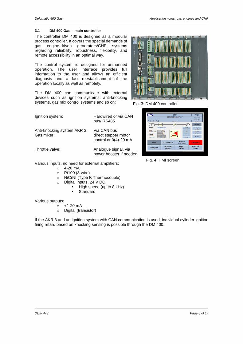
3.1 DM 400 Gas – main controller The controller DM 400 is designed as a modular process controller. It covers the special demands of gas engine-driven generators/CHP systems regarding reliability, robustness, flexibility, and remote accessibility in an optimal way. The control system is designed for unmanned operation. The user interface provides full information to the user and allows an efficient diagnosis and a fast reestablishment of the operation locally as well as remotely. The DM 400 can communicate with external devices such as ignition systems, anti-knocking systems, gas mix control systems and so on: Ignition system: Hardwired or via CAN
bus/ RS485 Anti-knocking system AKR 3: Via CAN bus Gas mixer: direct stepper motor
control or 0(4)-20 mA Throttle valve: Analogue signal, via
power booster if needed Various inputs, no need for external amplifiers:
o 4-20 mA o Pt100 (3-wire) o NiCrNI (Type K Thermocouple) o Digital inputs, 24 V DC
High speed (up to 8 kHz) Standard
Various outputs:
o +/- 20 mA o Digital (transistor)
If the AKR 3 and an ignition system with CAN communication is used, individual cylinder ignition firing retard based on knocking sensing is possible through the DM 400.
Fig. 3: DM 400 controller
Fig. 4: HMI screen
Delomatic 400 Gas Application notes, gas engines and CHP
DEIF A/S Page 9 of 14
3.2 Air/fuel mixers
DEIF can supply various kinds of mixers which are suitable for several types of gas like bio gas and natural gas. The mixers are based on proven technology and can provide efficient and precise control of air/fuel mixture as per the demand signal given by the controller. We have a range of gas mixers from compact mixers with integrated throttle body for small engines and limited space applications to large ring gap technology-based large cylinder volume engines. The mixer is coupled with the necessary driving arrangement like stepper motor or actuator which receives a demand signal from the controller via 0(4)-20 mA or stepper motor control, dependent on the mixer. The selection of mixer depends on a lot of parameters like make and model of engine, type of gas, air and fuel consumption requirement and piping design.
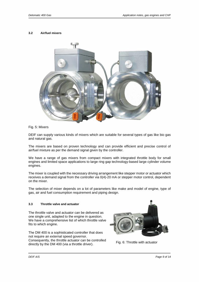
3.3 Throttle valve and actuator The throttle valve and actuator can be delivered as one single unit, adapted to the engine in question. We have a comprehensive list of which throttle valve fits to which engine. The DM 400 is a sophisticated controller that does not require an external speed governor. Consequently, the throttle actuator can be controlled directly by the DM 400 (via a throttle driver).
Fig. 5: Mixers
Fig. 6: Throttle with actuator

Delomatic 400 Gas Application notes, gas engines and CHP
DEIF A/S Page 10 of 14
3.4 Digital ignition control system The correct mixture of air and fuel is required to be ignited in the cylinder at the right time to produce the maximum power and minimum emission. The ignition system is employed so that it can activate the spark precisely at the right moment for each cylinder. The ignition system determines the position of piston by an inductive pick-up installed on the camshaft to produce the spark at the right moment. The ignition coils are selected so that the right amount of spark energy is provided to ignite the fuel mixture in the cylinder.
DEIF offers an intelligent, digital ignition system, which delivers precisely timed spark ignition with an adjustable energy level. Combining the right ignition system and ignition coils ensures optimal engine performance. The ignition system can communicate with the DM 400 controller and possibly receive necessary commands for adjustment of ignition angle in case of knocking (AKR 3 required).
Fig. 7: Ignition rail
Fig. 8: Ignition system

Delomatic 400 Gas Application notes, gas engines and CHP
DEIF A/S Page 11 of 14
3.5 Anti knocking system DEIF’s Anti Knocking Regulator (AKR 3) is a state-of-the art unit with knocking sensing based on single cylinder detection.
For correct knocking sensing, the AKR 3 uses digital FFT (Fast Fourier Transformation) to break down vibration data into individual frequencies and individual levels.
The use of FFT enables the AKR 3 to create an engine “image”, which represents the frequencies and levels produced by the normal engine state, including gear wheel noise, bearing noise, normal combustion noise, valve noise and so on.
Filtering the “image” frequencies precisely highlights knocking frequencies for monitoring and taking action when needed.
In combination with the DM 400 Gas and communication to the ignition system, the AKR 3 offers the possibility to control the ignition-firing angle for each individual cylinder and thereby prevent knocking without having to decrease the genset power output.
The “image”:
FFT analysis Knocking frequencies
Fig. 9: AKR 3
Fig. 10: FFT graphics

Delomatic 400 Gas Application notes, gas engines and CHP
DEIF A/S Page 12 of 14
4. Solution description, retrofits The DEIF engine control system solution can be used for retrofit of existing control systems, where the original system is removed and a DM 400 system is mounted instead. The approach is a 1:1 conversion. This means that the DM 400 can interface with parts of the system that remains on the engine such as ignition system, gas mixer or fuel metering valves, knocking detection system, or, if the knocking detection system is also removed, knocking sensors (requires mounting of the AKR 3). The DM 400 input/output layout will also be adapted so that all existing sensors are re-used. If needed, a complete system mounted in a panel can be provided. In this case, the original connection design (terminal strip or connector sockets) is used for ease of installation. Example:
DEIF has retrofitted various types and makes of gas gensets. Contact DEIF for further information.
Fig. 11: DM 400 retrofit

Delomatic 400 Gas Application notes, gas engines and CHP
DEIF A/S Page 13 of 14
5. Solution description, CHP The DM 400 controller has a built-in facility for control of a complete CHP system. The integration with the generator and engine control and protection makes the DEIF system easy to set up and operate.
5.1 Available combined controls
• Heating circuit o Control of 3-way valve o Monitoring of temperatures before and after heat exchanger o Monitoring of heating water flow o Energy counter
• Emergency cooler circuit (used if heating circuit is not always capable of consuming the cooling energy available)
o Control of 3-way valve (temperature-based) Valve can be placed before or after the emergency cooler
o Control of up to 3 cooler stages (sequential start of fans, based on 3-way valve position)
o Monitoring of cooling circuit pressure • Intercooler circuit
o Control of 3-way valve o Control based on air/gas mix temperature or coolant temperature o Control of up to 3 cooler stages
• Engine cooling circuit o Control of 3-way valve o Control based on coolant inlet temperature, with set point based on generator
power production o Monitoring of engine inlet and outlet temperatures o Post run of electric coolant pump
• Independent regulators o 4 independent PID regulators, fully configurable

Delomatic 400 Gas Application notes, gas engines and CHP
DEIF A/S Page 14 of 14
5.2 User interface The DM 400 has a built-in graphic presentation of the P&I diagram of the heating and cooling circuits combined.
The above picture shows all cooler stages. The screen presentation will adapt automatically to systems with less stages.
Fig. 12: CHP display


![No Model VIN 1 (DM) SANTAFE [DM] KMHSU81BSCU000212 2 … Engine YF and D… · 37 (dm) santafe [dm] kmhst81bsdu023920 38 (dm) santafe [dm] kmhst81bsdu023926 39 (dm) santafe [dm] kmhst81bsdu023930](https://img.dokumen.tips/doc/110x75/6017564e29e54a6dde7ebe6b/no-model-vin-1-dm-santafe-dm-kmhsu81bscu000212-2-engine-yf-and-d-37-dm-santafe.jpg)