Embed Size (px)
Citation preview
A Dell Appliance Architecture
Dell XC Web-Scale Converged Appliance for Wyse vWorkspace® Dell Engineering September 2015
A Dell Appliance Architecture
Revisions
Date Description
March 2015 Initial release
September 2015 Document overhaul
THIS DOCUMENT IS FOR INFORMATIONAL PURPOSES ONLY, AND MAY CONTAIN TYPOGRAPHICAL ERRORS AND
TECHNICAL INACCURACIES. THE CONTENT IS PROVIDED AS IS, HARDWARE SELECTIONS CONTAINED WITHIN ARE
FROM THE BASIS OF BEST WITHOUT EXPRESS OR IMPLIED WARRANTIES OF ANY KIND.
Copyright © 2015 Dell Inc. All rights reserved. Reproduction of this material in any manner whatsoever without the
express written permission of Dell Inc. is strictly forbidden. For more information, contact Dell.
Dell, the Dell logo, and the Dell badge are trademarks of Dell Inc. Microsoft and Windows are registered trademarks of
Microsoft Corporation in the United States and/or other countries. VMware is a registered trademark of VMware, Inc.
NVIDIA GRID™ and vGPU™ are registered trademarks of NVIDIA Corporation. Other trademarks and trade names may
be used in this document to refer to either the entities claiming the marks and names or their products. Dell Inc.
disclaims any proprietary interest in trademarks and trade names other than its own.

A Dell Appliance Architecture
Contents 1 Introduction ................................................................................................................................................................................ 6
1.1 Purpose ............................................................................................................................................................................. 6
1.2 Scope ................................................................................................................................................................................ 6
1.3 What’s New ...................................................................................................................................................................... 6
2 Solution Architecture Overview .............................................................................................................................................. 7
2.1 Introduction ..................................................................................................................................................................... 7
2.2 Nutanix Architecture....................................................................................................................................................... 7
2.3 Nutanix Web-scale Converged Infrastructure ........................................................................................................... 9
2.4 Dell XC Web Scale – Solution Pods ............................................................................................................................ 11
Network Architecture ................................................................................................................................................... 12
3 Hardware Components .......................................................................................................................................................... 14
3.1 Network .......................................................................................................................................................................... 14
Dell Networking S60 (1Gb ToR Switch) .................................................................................................................... 14
Dell Networking S4810 (10Gb ToR Leaf Switch) ..................................................................................................... 15
3.2 Dell XC Converged Appliance .................................................................................................................................... 17
Dell XC630 (A5) ............................................................................................................................................................. 18
Dell XC630 (B5) ............................................................................................................................................................. 18
Dell XC630 (B7) ............................................................................................................................................................. 19
3.3 Dell Wyse Cloud Clients .............................................................................................................................................. 20
Wyse 3020 Thin Client (ThinOS) ................................................................................................................................ 20
Wyse 5010 Thin Client (ThinOS) ................................................................................................................................. 21
Wyse 5010 Thin Client (Windows Embedded Standard 8) .................................................................................... 21
Wyse 7010 Thin Client (Windows Embedded Standard 8) .................................................................................... 21
Wyse 5040 AIO .............................................................................................................................................................. 22
Dell Wyse Cloud Connect ........................................................................................................................................... 22
Dell Venue 11 Pro .......................................................................................................................................................... 22
Dell Chromebook 11 ..................................................................................................................................................... 23
4 Software Components ............................................................................................................................................................ 24
4.1 Dell Wyse vWorkspace ................................................................................................................................................. 24
Wyse vWorkspace Deployment Options .................................................................................................................. 25

A Dell Appliance Architecture
Hyper-V Catalyst ........................................................................................................................................................... 26
RDSH Integration into Dell Wyse Datacenter Architecture ................................................................................... 27
4.2 Hypervisor Platforms .................................................................................................................................................... 29
VMware vSphere 6 ........................................................................................................................................................ 29
Microsoft Windows Server 2012 R2 Hyper-V .......................................................................................................... 30
5 Solution Architecture for Wyse vWorkspace ...................................................................................................................... 31
5.1 Management Role Configuration ............................................................................................................................... 31
vSphere Management Role Requirements ............................................................................................................... 31
Hyper-V Management Role Requirements .............................................................................................................. 32
RDSH ............................................................................................................................................................................... 32
SQL Databases ............................................................................................................................................................... 33
DNS .................................................................................................................................................................................. 33
5.2 Storage Architecture Overview .................................................................................................................................. 34
Nutanix Containers ....................................................................................................................................................... 34
5.3 Virtual Networking ........................................................................................................................................................ 35
vSphere ........................................................................................................................................................................... 35
Hyper-V........................................................................................................................................................................... 36
5.4 Scaling Guidance .......................................................................................................................................................... 38
5.5 Solution High Availability ............................................................................................................................................ 40
5.6 Dell Wyse Datacenter for VWorkspace Communication Flow ............................................................................. 41
6 Solution Performance and Testing ....................................................................................................................................... 42
6.1 Load Generation and Monitoring ............................................................................................................................... 42
Login VSI 4 – Login Consultants ................................................................................................................................ 42
VMware vCenter ............................................................................................................................................................ 42
Microsoft Perfmon ........................................................................................................................................................ 42
6.2 Performance Analysis Methodology .......................................................................................................................... 42
Resource Utilization...................................................................................................................................................... 43
Dell Wyse Datacenter Workloads and Profiles ........................................................................................................ 44
Dell Wyse Datacenter Workloads ............................................................................................................................... 44
6.3 Testing and Validation .................................................................................................................................................. 46
Testing Process ............................................................................................................................................................. 46
6.4 vWorkspace Test Results ............................................................................................................................................. 47

A Dell Appliance Architecture
Acknowledgements ....................................................................................................................................................................... 60
About the Authors ........................................................................................................................................................................... 61

A Dell Appliance Architecture
1 Introduction
1.1 Purpose This document addresses the architecture design, configuration and implementation considerations for
the key components required to deliver virtual desktops or shared sessions via Wyse vWorkspace® on
Microsoft® Windows Server® Hyper-V® 2012 R2 or VMware® vSphere® 6.
1.2 Scope Relative to delivering the virtual desktop environment, the objectives of this document are to:
Define the detailed technical design for the solution.
Define the hardware requirements to support the design.
Define the constraints which are relevant to the design.
Define relevant risks, issues, assumptions and concessions – referencing existing ones where possible.
Provide a breakdown of the design into key elements such that the reader receives an incremental or
modular explanation of the design.
Provide solution scaling and component selection guidance.
1.3 What’s New
Introduce support for VMware vSphere 6
Introduce support for Wyse vWorkspace 8.6

A Dell Appliance Architecture
2 Solution Architecture Overview
2.1 Introduction The Dell XC series delivers an out-of-the-box infrastructure solution for virtual desktops that eliminates
the high cost, variable performance, and extensive risk of conventional solutions. The Nutanix™ web-scale
converged infrastructure is a turnkey solution that comes ready to run your VDI solution of choice. The
Nutanix platform’s unique architecture allows enterprises to scale their virtual desktops from 50 to tens of
thousands of desktops in a linear fashion, providing customers with a simple path to enterprise
deployment with the agility of public cloud providers.
2.2 Nutanix Architecture The Nutanix web-scale converged infrastructure is a scale-out cluster of high-performance nodes (or
servers), each running a standard hypervisor and containing processors, memory, and local storage
(consisting of SSD Flash and high capacity SATA disk drives). Each node runs virtual machines just like a
standard virtual machine host.
In addition, local storage from all nodes is virtualized into a unified pool by the Nutanix Distributed File
System (NDFS). In effect, NDFS acts like an advanced NAS that uses local SSDs and disks from all nodes to

A Dell Appliance Architecture
store virtual machine data. Virtual machines running on the cluster write data to NDFS as if they were
writing to shared storage.
NDFS understand the concept of a virtual machine and provides advanced data management features. It
brings data closer to virtual machines by storing the data locally on the system, resulting in higher
performance at a lower cost. Nutanix platforms can horizontally scale from as few as three nodes to a
large number of nodes, enabling organizations to scale their infrastructure as their needs grow.
The Nutanix Elastic Deduplication Engine is a software-driven, massively scalable and intelligent data
reduction technology. It increases the effective capacity in the disk tier, as well as the RAM and flash cache
tiers of the system, by eliminating duplicate data. This substantially increases storage efficiency, while also
improving performance due to larger effective cache capacity in RAM and flash. Deduplication is
performed by each node individually in the cluster, allowing for efficient and uniform deduplication at
scale. This technology is increasingly effective with full/persistent clones or P2V migrations.
Nutanix Shadow Clones delivers distributed localized caching of virtual disks performance in multi-reader
scenarios, such as desktop virtualization using Wyse vWorkspace or RDSH. With Shadow Clones, the CVM
NDFSNDFS
Only a single instance of the shared VM data is pulled into the cache upon read
StorageStorage
... VM NVM NVM 1VM 1
CacheCache
HypervisorHypervisor
CacheCVMCVM
Each node participates in, and performs, its own fingerprinting and deduplication
StorageStorage
... VM NVM NVM 1VM 1
CacheCache
HypervisorHypervisor
CacheCVMCVM
Sequential streams of data are fingerprinted at 4K granularity for efficient deduplication
StorageStorage
... VM NVM NVM 1VM 1
CacheCache
HypervisorHypervisor
CacheCVMCVM
...

A Dell Appliance Architecture
actively monitors virtual disk access trends. If there are requests originating from more than two remote
CVMs, as well as the local CVM, and all of the requests are read I/O and the virtual disk will be marked as
immutable. Once the disk has been marked immutable, the virtual disk is then cached locally by each
CVM, so read operations are now satisfied locally by local storage.
The benefits of the Nutanix Platform are now exposed to scale out vSphere or Hyper-V deployments:
2.3 Nutanix Web-scale Converged Infrastructure The Nutanix web-scale converged infrastructure provides an ideal combination of both high-performance
compute with localized storage to meet any demand. True to this capability, this reference architecture
contains zero reconfiguration of or customization to the Nutanix product to optimize for this use case.
The next figure shows a high-level example of the relationship between an XC node, storage pool,
container, pod and relative scale out:

A Dell Appliance Architecture
Dell XC Web Scale allows organizations to deliver virtualized or remote desktops and applications through
a single platform and support end users with access to all of their desktops and applications in a single
place.

A Dell Appliance Architecture
2.4 Dell XC Web Scale – Solution Pods The networking layer consists of the 10Gb Dell Networking S4810 utilized to build a world-class leaf/spine
architecture with robust 1Gb switching in the S60 for iDRAC connectivity.
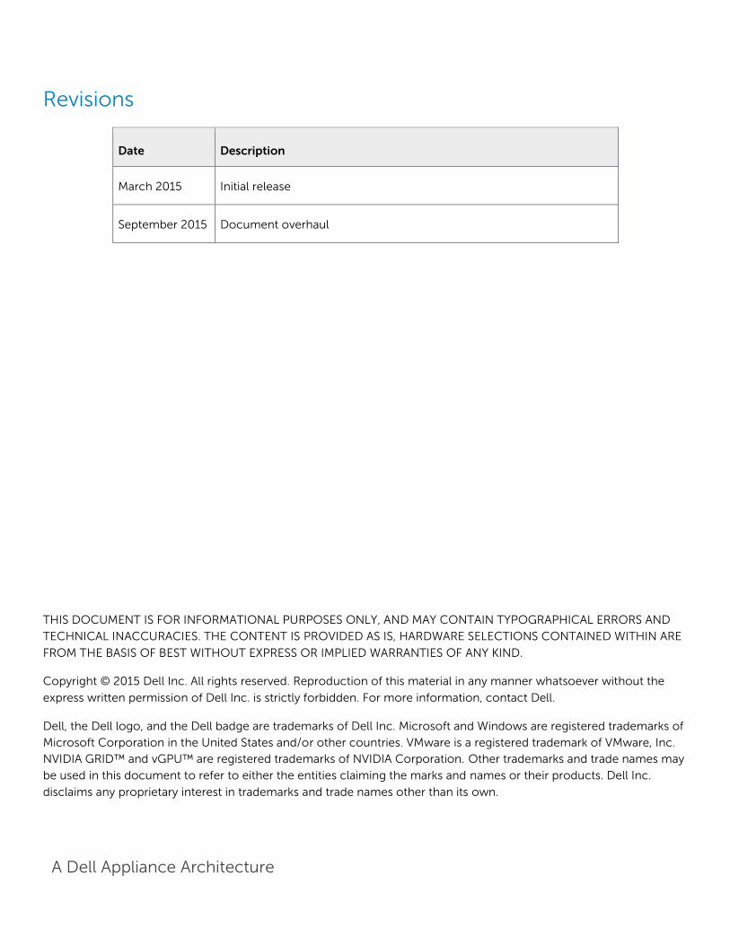
The compute, management and storage layers are converged into a single server XC Series appliance
cluster, hosting either VMware vSphere or Microsoft Hyper-V hypervisors. The recommended boundaries
of an individual pod are based on number of nodes supported within a given hypervisor cluster, 64 nodes
for vSphere or Hyper-V.
Dell recommends that the VDI management infrastructure nodes be separated from the compute
resources onto their own appliance cluster with a common storage namespace shared between them
based on NFS for vSphere or SMB for Hyper-V. One node for VDI management is required, minimally, and
expanded based on size of the pod. The designations ds_rdsh, ds_compute, and ds_mgmt as seen below
are logical NDFS containers used to group VMs of a particular type. Using distinct containers allows
features and attributes, such as compression and deduplication, to be applied to groups of VMs that share
similar characteristics. Compute hosts can be used interchangeably for RDSH or RDSH as required.
Distinct clusters should be built for management and compute hosts for HA, respectively, to plan
predictable failover, scale and load across the pod. The NFS or SMB namespace can be shared across
multiple hypervisor clusters adding disk capacity and performance for each distinct cluster.
A Dell Appliance Architecture
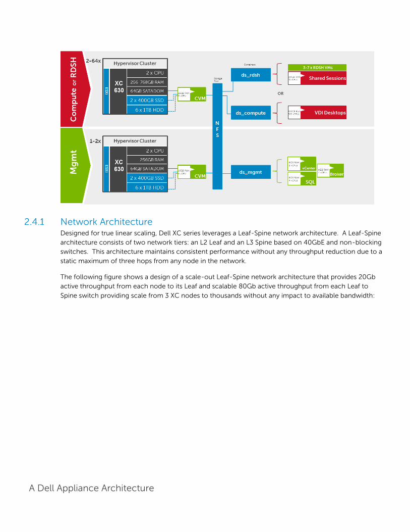
Network Architecture Designed for true linear scaling, Dell XC series leverages a Leaf-Spine network architecture. A Leaf-Spine
architecture consists of two network tiers: an L2 Leaf and an L3 Spine based on 40GbE and non-blocking
switches. This architecture maintains consistent performance without any throughput reduction due to a
static maximum of three hops from any node in the network.
The following figure shows a design of a scale-out Leaf-Spine network architecture that provides 20Gb
active throughput from each node to its Leaf and scalable 80Gb active throughput from each Leaf to
Spine switch providing scale from 3 XC nodes to thousands without any impact to available bandwidth:

A Dell Appliance Architecture
4
LAG
10 Gb/s
40+ Gb/s
MLAG Link
4
4
4
4
4
4
4
4
4
4
QSFP+
MASTERSYS FAN PSU
RS-232
ETHERNETLNK ACT4644424038363432302826242220181614121086420 48 56
52 60
SFP+
Force10 S4810P
4
4
4
4
4
4
4
4
4
4
4
L2 Leaf
QSFP+
MASTERSYS FAN PSU
RS-232
ETHERNETLNK ACT4644424038363432302826242220181614121086420 48 56
52 60
SFP+
Force10 S4810P
4
QSFP+
MASTERSYS FAN PSU
RS-232
ETHERNETLNK ACT4644424038363432302826242220181614121086420 48 56
52 60
SFP+
Force10 S4810P
QSFP+
MASTERSYS FAN PSU
RS-232
ETHERNETLNK ACT4644424038363432302826242220181614121086420 48 56
52 60
SFP+
Force10 S4810P
4
18 2014 1610 126 82 4 30 3226 2822 24
17 1913 159 115 71 3 29 3125 2721 23 33SFP+
34SFP+
Stack ID
EST
L3 Spine
18 2014 1610 126 82 4 30 3226 2822 24
17 1913 159 115 71 3 29 3125 2721 23 33SFP+
34SFP+
Stack ID
EST

A Dell Appliance Architecture
3 Hardware Components
3.1 Network The following sections contain the core network components for the Dell Wyse Datacenter solutions.
General uplink cabling guidance to consider in all cases is that TwinAx is very cost effective for short 10Gb
runs and for longer runs use fiber with SFPs.
Dell Networking S60 (1Gb ToR Switch) The Dell Networking S-Series S60 is a high-performance 1/ 10Gb access switch optimized for lowering
operational costs at the network edge and is recommended for iDRAC connectivity. The S60 answers the
key challenges related to network congestion in data center ToR (Top-of-Rack) and service provider
aggregation deployments. As the use of bursty applications and services continue to increase, huge spikes
in network traffic that can cause network congestion and packet loss, also become more common. The
S60 is equipped with the industry’s largest packet buffer (1.25 GB), enabling it to deliver lower application
latency and maintain predictable network performance even when faced with significant spikes in network
traffic. Providing 48 line-rate Gb ports and up to four optional 10Gb uplinks in just 1-RU, the S60
conserves valuable rack space. Further, the S60 design delivers unmatched configuration flexibility, high
reliability, and power and cooling efficiency to reduce costs.
Model Features Options Uses
Dell Networking
S60
44 x BaseT (10/100/1000)
+ 4 x SFP
High performance
High Scalability
Redundant PSUs 1Gb
connectivity
for iDRAC
4 x 1Gb SFP ports the
support copper or fiber
12Gb or 24Gb stacking
(up to 12 switches)
2 x modular slots for
10Gb uplinks or
stacking modules

A Dell Appliance Architecture
Guidance:
10Gb uplinks to a core or distribution switch are the preferred design choice using the rear 10Gb uplink
modules. If 10Gb to a core or distribution switch is unavailable the front 4 x 1Gb SFP ports are used.
The front 4 SFP ports can support copper cabling and are upgraded to optical if a longer run is needed.
For more information on the S60 switch and Dell Networking, please visit: LINK
3.1.1.1 S60 Stacking The S60 switches are optionally stacked with 2 or more switches, if greater port count or redundancy is
desired. Each switch will need a stacking module plugged into a rear bay and connected with a stacking
cable. The best practice for switch stacks greater than 2 is to cable in a ring configuration with the last
switch in the stack cabled back to the first. Uplinks need to be configured on all switches in the stack back
to the core to provide redundancy and failure protection.
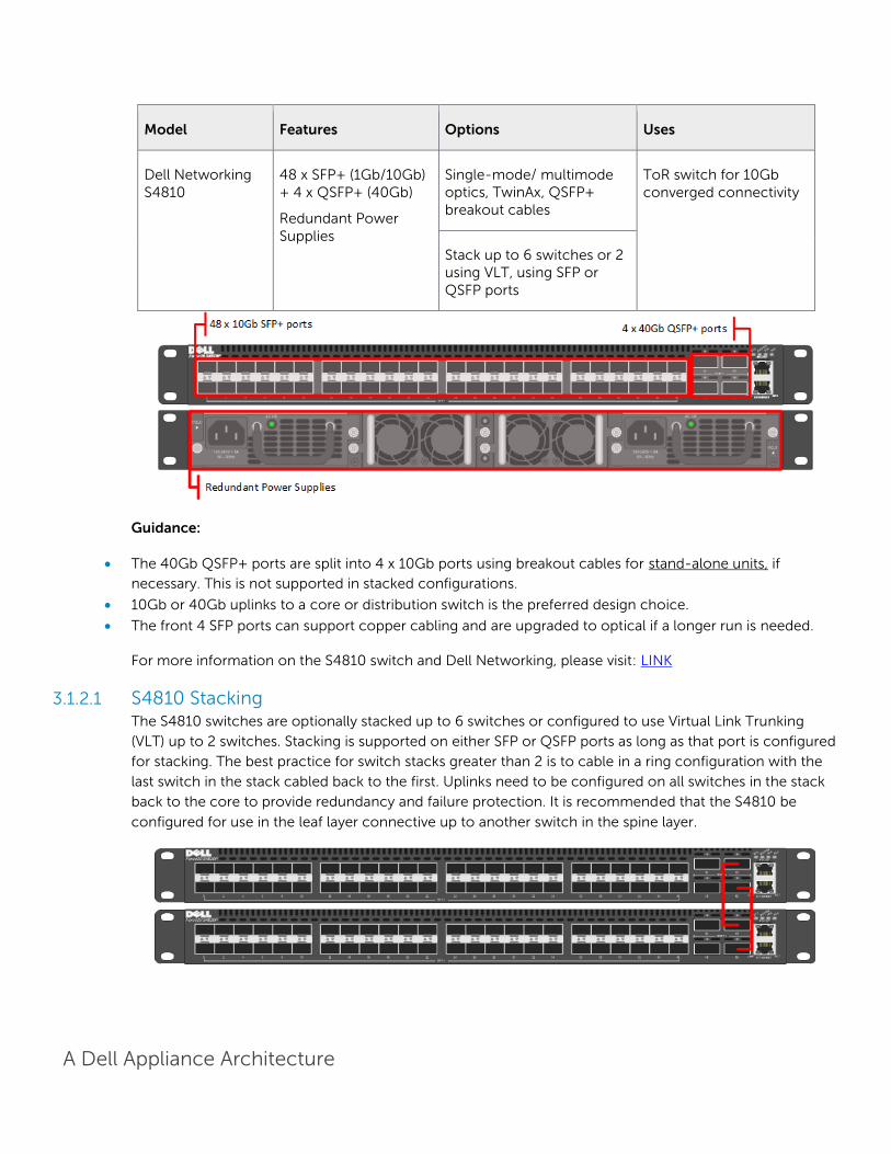
Dell Networking S4810 (10Gb ToR Leaf Switch) The Dell Networking S-Series S4810 is an ultra-low latency 10/40Gb Top-of-Rack (ToR) switch purpose-
built for applications in high-performance data center and computing environments. Leveraging a non-
blocking, cut-through switching architecture, the S4810 delivers line-rate L2 and L3 forwarding capacity
with ultra-low latency to maximize network performance. The compact S4810 design provides industry-
leading density of 48 dual-speed 1/10Gb (SFP+) ports as well as four 40Gb QSFP+ uplinks to conserve
valuable rack space and simplify the migration to 40Gb in the data center core (Each 40Gb QSFP+ uplink
can support four 10Gb ports with a breakout cable). Priority-based Flow Control (PFC), Data Center Bridge
Exchange (DCBX), Enhance Transmission Selection (ETS), coupled with ultra-low latency and line rate
throughput, make the S4810 ideally suited for converged leaf/spine environments.
A Dell Appliance Architecture
Model Features Options Uses
Dell Networking S4810
48 x SFP+ (1Gb/10Gb) + 4 x QSFP+ (40Gb)
Redundant Power Supplies
Single-mode/ multimode optics, TwinAx, QSFP+ breakout cables
ToR switch for 10Gb converged connectivity
Stack up to 6 switches or 2 using VLT, using SFP or QSFP ports
Guidance:
The 40Gb QSFP+ ports are split into 4 x 10Gb ports using breakout cables for stand-alone units, if
necessary. This is not supported in stacked configurations.
10Gb or 40Gb uplinks to a core or distribution switch is the preferred design choice.
The front 4 SFP ports can support copper cabling and are upgraded to optical if a longer run is needed.
For more information on the S4810 switch and Dell Networking, please visit: LINK
3.1.2.1 S4810 Stacking The S4810 switches are optionally stacked up to 6 switches or configured to use Virtual Link Trunking
(VLT) up to 2 switches. Stacking is supported on either SFP or QSFP ports as long as that port is configured
for stacking. The best practice for switch stacks greater than 2 is to cable in a ring configuration with the
last switch in the stack cabled back to the first. Uplinks need to be configured on all switches in the stack
back to the core to provide redundancy and failure protection. It is recommended that the S4810 be
configured for use in the leaf layer connective up to another switch in the spine layer.
A Dell Appliance Architecture
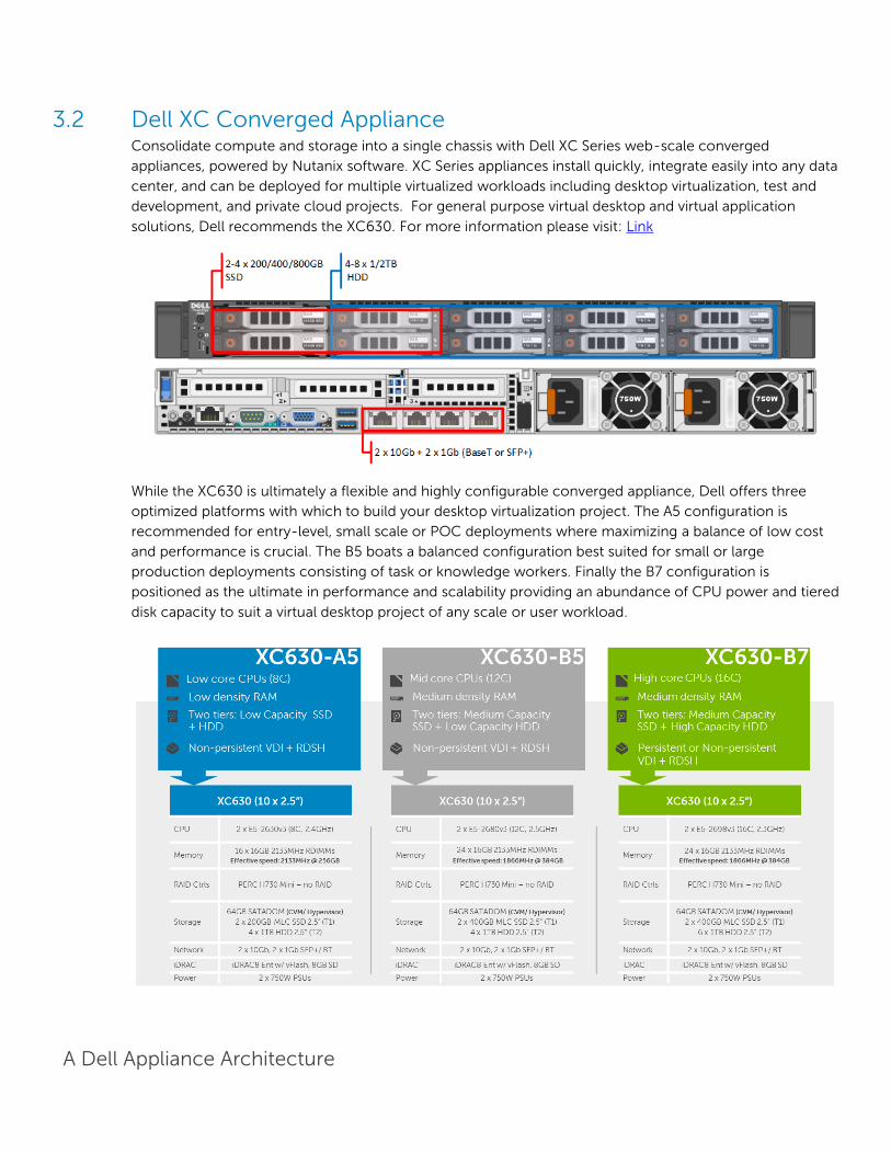
3.2 Dell XC Converged Appliance Consolidate compute and storage into a single chassis with Dell XC Series web-scale converged
appliances, powered by Nutanix software. XC Series appliances install quickly, integrate easily into any data
center, and can be deployed for multiple virtualized workloads including desktop virtualization, test and
development, and private cloud projects. For general purpose virtual desktop and virtual application
solutions, Dell recommends the XC630. For more information please visit: Link
While the XC630 is ultimately a flexible and highly configurable converged appliance, Dell offers three
optimized platforms with which to build your desktop virtualization project. The A5 configuration is
recommended for entry-level, small scale or POC deployments where maximizing a balance of low cost
and performance is crucial. The B5 boats a balanced configuration best suited for small or large
production deployments consisting of task or knowledge workers. Finally the B7 configuration is
positioned as the ultimate in performance and scalability providing an abundance of CPU power and tiered
disk capacity to suit a virtual desktop project of any scale or user workload.
A Dell Appliance Architecture
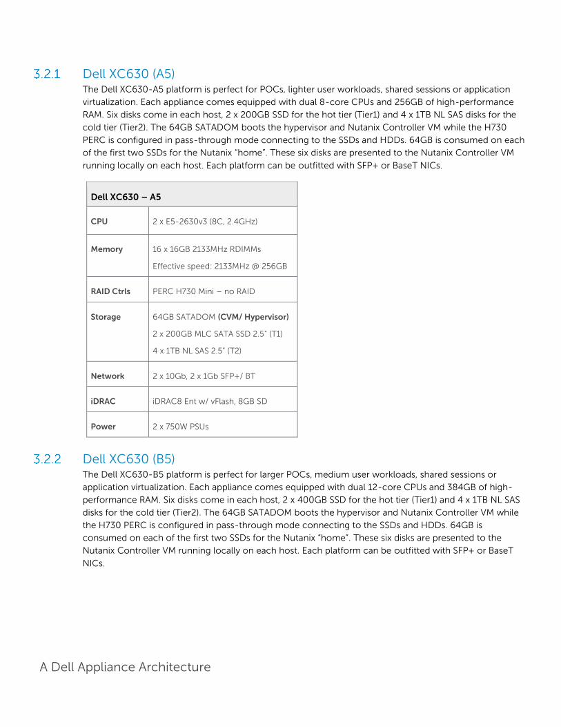
Dell XC630 (A5) The Dell XC630-A5 platform is perfect for POCs, lighter user workloads, shared sessions or application
virtualization. Each appliance comes equipped with dual 8-core CPUs and 256GB of high-performance
RAM. Six disks come in each host, 2 x 200GB SSD for the hot tier (Tier1) and 4 x 1TB NL SAS disks for the
cold tier (Tier2). The 64GB SATADOM boots the hypervisor and Nutanix Controller VM while the H730
PERC is configured in pass-through mode connecting to the SSDs and HDDs. 64GB is consumed on each
of the first two SSDs for the Nutanix “home”. These six disks are presented to the Nutanix Controller VM
running locally on each host. Each platform can be outfitted with SFP+ or BaseT NICs.
Dell XC630 – A5
CPU 2 x E5-2630v3 (8C, 2.4GHz)
Memory 16 x 16GB 2133MHz RDIMMs
Effective speed: 2133MHz @ 256GB
RAID Ctrls PERC H730 Mini – no RAID
Storage 64GB SATADOM (CVM/ Hypervisor)
2 x 200GB MLC SATA SSD 2.5” (T1)
4 x 1TB NL SAS 2.5” (T2)
Network 2 x 10Gb, 2 x 1Gb SFP+/ BT
iDRAC iDRAC8 Ent w/ vFlash, 8GB SD
Power 2 x 750W PSUs
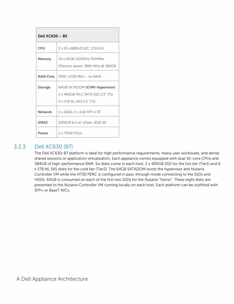
Dell XC630 (B5) The Dell XC630-B5 platform is perfect for larger POCs, medium user workloads, shared sessions or
application virtualization. Each appliance comes equipped with dual 12-core CPUs and 384GB of high-
performance RAM. Six disks come in each host, 2 x 400GB SSD for the hot tier (Tier1) and 4 x 1TB NL SAS
disks for the cold tier (Tier2). The 64GB SATADOM boots the hypervisor and Nutanix Controller VM while
the H730 PERC is configured in pass-through mode connecting to the SSDs and HDDs. 64GB is
consumed on each of the first two SSDs for the Nutanix “home”. These six disks are presented to the
Nutanix Controller VM running locally on each host. Each platform can be outfitted with SFP+ or BaseT
NICs.
A Dell Appliance Architecture
Dell XC630 – B5
CPU 2 x E5-2680v3 (12C, 2.5GHz)
Memory 24 x 16GB 2133MHz RDIMMs
Effective speed: 1866 MHz @ 384GB
RAID Ctrls PERC H730 Mini – no RAID
Storage 64GB SATADOM (CVM/ Hypervisor)
2 x 400GB MLC SATA SSD 2.5” (T1)
4 x 1TB NL SAS 2.5” (T2)
Network 2 x 10Gb, 2 x 1Gb SFP+/ BT
iDRAC iDRAC8 Ent w/ vFlash, 8GB SD
Power 2 x 750W PSUs
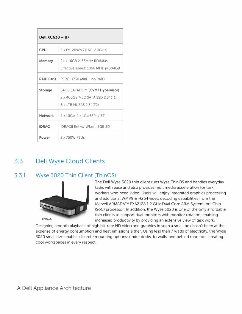
Dell XC630 (B7) The Dell XC630-B7 platform is ideal for high performance requirements, heavy user workloads, and dense
shared sessions or application virtualization. Each appliance comes equipped with dual 16-core CPUs and
384GB of high-performance RAM. Six disks come in each host, 2 x 400GB SSD for the hot tier (Tier1) and 6
x 1TB NL SAS disks for the cold tier (Tier2). The 64GB SATADOM boots the hypervisor and Nutanix
Controller VM while the H730 PERC is configured in pass-through mode connecting to the SSDs and
HDDs. 64GB is consumed on each of the first two SSDs for the Nutanix “home”. These eight disks are
presented to the Nutanix Controller VM running locally on each host. Each platform can be outfitted with
SFP+ or BaseT NICs.
A Dell Appliance Architecture
Dell XC630 – B7
CPU 2 x E5-2698v3 (16C, 2.3GHz)
Memory 24 x 16GB 2133MHz RDIMMs
Effective speed: 1866 MHz @ 384GB
RAID Ctrls PERC H730 Mini – no RAID
Storage 64GB SATADOM (CVM/ Hypervisor)
2 x 400GB MLC SATA SSD 2.5” (T1)
6 x 1TB NL SAS 2.5” (T2)
Network 2 x 10Gb, 2 x 1Gb SFP+/ BT
iDRAC iDRAC8 Ent w/ vFlash, 8GB SD
Power 2 x 750W PSUs
3.3 Dell Wyse Cloud Clients
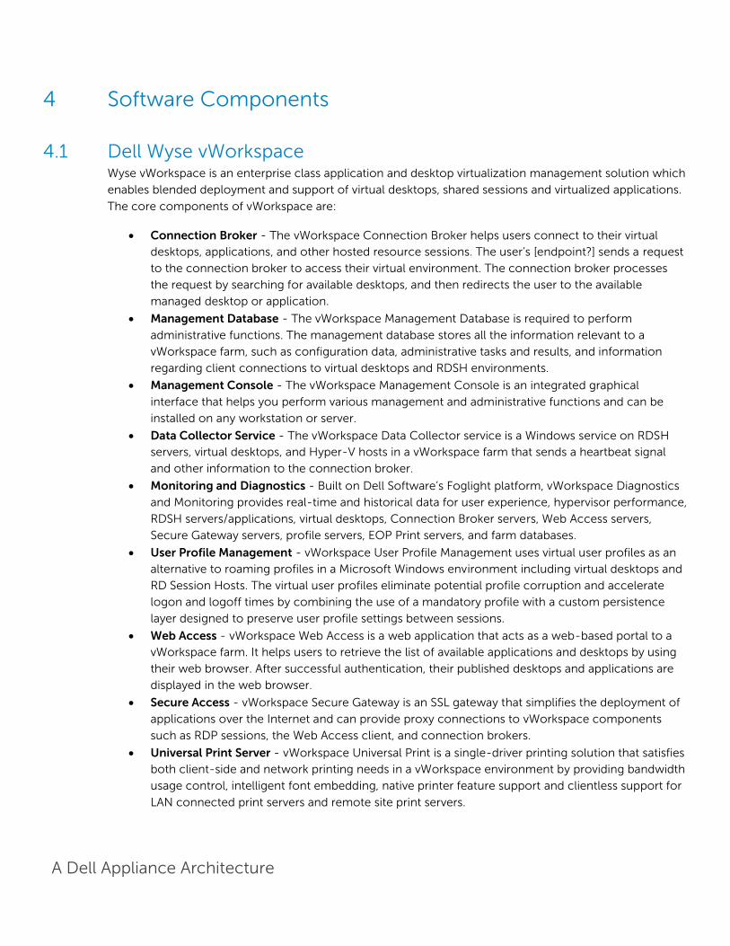
Wyse 3020 Thin Client (ThinOS) The Dell Wyse 3020 thin client runs Wyse ThinOS and handles everyday
tasks with ease and also provides multimedia acceleration for task
workers who need video. Users will enjoy integrated graphics processing
and additional WMV9 & H264 video decoding capabilities from the
Marvell ARMADA™ PXA2128 1.2 GHz Dual Core ARM System-on-Chip
(SoC) processor. In addition, the Wyse 3020 is one of the only affordable
thin clients to support dual monitors with monitor rotation, enabling
increased productivity by providing an extensive view of task work.
Designing smooth playback of high bit-rate HD video and graphics in such a small box hasn’t been at the
expense of energy consumption and heat emissions either. Using less than 7 watts of electricity, the Wyse
3020 small size enables discrete mounting options: under desks, to walls, and behind monitors, creating
cool workspaces in every respect.

A Dell Appliance Architecture
Wyse 5010 Thin Client (ThinOS) Ultra-high performance in a compact package Power users and
knowledge workers will love the exceptionally fast speed and power
from the dual-core driven Dell Wyse 5010 thin client running Wyse
ThinOS. With a 1.4 GHz AMD G series APU with integrated graphics
engine, the Wyse 5010 handles everything from demanding
multimedia applications to business content creation and
consumption with ease. The Wyse 5010 even supports power users’
most demanding workloads: high quality audio and video, unified
communications, CAD/CAM, 3D simulation and modelling, HD Flash
and multimedia, and dual digital high resolution displays with rotation. Users will enjoy smooth roaming
and super-fast 802.11 a/b/g/n wireless at 2.4 and 5 GHz with dual antennas. The Wyse 5010 (ThinOS) is
Citrix HDX, Microsoft® RemoteFX, and VMware® Horizon View certified. It also supports legacy
peripherals via an optional USB adapter. Averaging 9 watts, each and every Wyse 5010 contributes –
quietly and coolly – to lowering your organization’s carbon footprint, with reduced power usage and
emissions.
Wyse 5010 Thin Client (Windows Embedded Standard 8) A strong, reliable thin client, the Dell Wyse 5010 thin client runs Windows
Embedded Standard 8 and packs dual-core processing power into a compact
form factor for knowledge workers who need performance for demanding
virtual Windows® desktops and cloud applications. It’s also great for kiosks,
and multi-touch displays in a wide variety of environments, including
manufacturing, hospitality, retail, and healthcare. It features dual-core
processing power and an integrated graphics engine for a fulfilling Windows®
8 user experience. Knowledge workers will enjoy rich content creation and
consumption as well as everyday multimedia. Kiosk displays will look great on
a thin client that is Microsoft RemoteFX®, Citrix® HDX, VMware PCoIP, and HD video-enabled. Operating
with less than 9 watts of energy, the Dell Wyse 5010 (Windows) offers cool, quiet operations, potentially
lowering your overall carbon footprint.
Wyse 7010 Thin Client (Windows Embedded Standard 8) The versatile Dell Wyse 7010 thin client runs Windows Embedded
Standard 8 and gives people the freedom to mix and match a broad
range of legacy and cutting edge peripheral devices. Ports for parallel,
serial, and USB 3.0 offer fast, flexible connectivity. Like all Dell Wyse
cloud clients, the new Dell Wyse 7010 (Windows) is one cool operator.
Its energy efficient processor – which out-performs other more power-
hungry alternatives – and silent fan-less design, all contribute to help
lower an organization’s carbon footprint through power requirements
that are a fraction of traditional desktop PCs.

A Dell Appliance Architecture
Wyse 5040 AIO The Dell Wyse 5040 AIO all-in-one (AIO) offers versatile
connectivity options for use in a wide range of industries. With
four USB 2.0 ports, Gigabit Ethernet and integrated dual band
Wi-Fi options, users can link to their peripherals and quickly
connect to the network while working with processing-
intensive, graphics-rich applications. Built-in speakers, a
camera and a microphone make video conferencing and
desktop communication simple and easy. It even supports a
second attached display for those who need a dual monitor
configuration. A simple one-cord design and out-of-box
automatic setup makes deployment effortless while remote
management from a simple file server, Wyse Device Manager
(WDM), or Wyse Cloud Client Manager can help lower your total cost of ownership as you grow from just
a few thin clients to tens of thousands.
Dell Wyse Cloud Connect Designed to promote bring-your-own-device (BYOD) environments, Dell Wyse
Cloud Connect allows you to securely access and share work and personal files,
presentations, applications and other content from your business or your home.
Managed through Dell Wyse Cloud Client Manager software-as-a-service (SaaS), IT
managers can ensure that each Cloud Connect device is used by the appropriate
person with the right permissions and access to the appropriate apps and content
based on role, department and location. Slightly larger than a USB memory stick,
Cloud Connect is an ultra-compact multimedia-capable device. Simply plug it into
any available Mobile High-Definition Link (MHL) / HDMI port on a TV or monitor,
attach a Bluetooth keyboard and mouse, and you’re off and running. Easy to slip into your pocket or bag, it
enables an HD-quality window to the cloud, great for meetings and presentations while on business travel,
or for cruising the internet and checking email after a day of work. For more information, please visit: Link
Dell Venue 11 Pro Meet the ultimate in productivity, connectivity and collaboration. Enjoy full
laptop performance in an ultra-portable tablet that has unmatched flexibility
for a business in motion. This dual purpose device works as a tablet when
you're out in the field but also enables you to work on your desktop in the
office thanks to an optional dock. For more information, please visit: Link

A Dell Appliance Architecture
Dell Chromebook 11 The lightweight, easy-to-use Dell Chromebook 11 helps turn education into
exploration - without the worries of safety or security. Priced to make 1:1
computing affordable today, Chromebook 11 is backed by Dell support
services to make the most of your budget for years to come. The Chrome
OS and Chrome browser get students online in an instant and loads web
pages in seconds. A high-density battery supported by a 4th Gen Intel®
processor provides up to 10 hours of power. Encourage creativity with the
Chromebook 11 and its multimedia features that include an 11.6" screen, stereo sound and webcam.
A Dell Appliance Architecture
4 Software Components
4.1 Dell Wyse vWorkspace Wyse vWorkspace is an enterprise class application and desktop virtualization management solution which
enables blended deployment and support of virtual desktops, shared sessions and virtualized applications.
The core components of vWorkspace are:
Connection Broker - The vWorkspace Connection Broker helps users connect to their virtual
desktops, applications, and other hosted resource sessions. The user’s [endpoint?] sends a request
to the connection broker to access their virtual environment. The connection broker processes
the request by searching for available desktops, and then redirects the user to the available
managed desktop or application.
Management Database - The vWorkspace Management Database is required to perform
administrative functions. The management database stores all the information relevant to a
vWorkspace farm, such as configuration data, administrative tasks and results, and information
regarding client connections to virtual desktops and RDSH environments.
Management Console - The vWorkspace Management Console is an integrated graphical
interface that helps you perform various management and administrative functions and can be
installed on any workstation or server.
Data Collector Service - The vWorkspace Data Collector service is a Windows service on RDSH
servers, virtual desktops, and Hyper-V hosts in a vWorkspace farm that sends a heartbeat signal
and other information to the connection broker.
Monitoring and Diagnostics - Built on Dell Software’s Foglight platform, vWorkspace Diagnostics
and Monitoring provides real-time and historical data for user experience, hypervisor performance,
RDSH servers/applications, virtual desktops, Connection Broker servers, Web Access servers,
Secure Gateway servers, profile servers, EOP Print servers, and farm databases.
User Profile Management - vWorkspace User Profile Management uses virtual user profiles as an
alternative to roaming profiles in a Microsoft Windows environment including virtual desktops and
RD Session Hosts. The virtual user profiles eliminate potential profile corruption and accelerate
logon and logoff times by combining the use of a mandatory profile with a custom persistence
layer designed to preserve user profile settings between sessions.
Web Access - vWorkspace Web Access is a web application that acts as a web-based portal to a
vWorkspace farm. It helps users to retrieve the list of available applications and desktops by using
their web browser. After successful authentication, their published desktops and applications are
displayed in the web browser.
Secure Access - vWorkspace Secure Gateway is an SSL gateway that simplifies the deployment of
applications over the Internet and can provide proxy connections to vWorkspace components
such as RDP sessions, the Web Access client, and connection brokers.
Universal Print Server - vWorkspace Universal Print is a single-driver printing solution that satisfies
both client-side and network printing needs in a vWorkspace environment by providing bandwidth
usage control, intelligent font embedding, native printer feature support and clientless support for
LAN connected print servers and remote site print servers.
A Dell Appliance Architecture
vWorkspace 8.6 includes support for Microsoft Windows Server 2012 R2, Windows 8.1, Windows 10 Lync
2013, and App-V 5.0 as well as provides several enhancements to Diagnostics and Monitoring, Hyper-V
Catalyst Components, Dell EOP and more.
For additional information about the enhancements in Dell vWorkspace 8.6, please visit:
http://documents.quest.com/book/2057
Wyse vWorkspace Deployment Options Wyse vWorkspace provides a number of delivery options to meet your needs, all within a single, simple,
wizard-driven environment that is easy to set up and manage.
RD Session Host Sessions – Provide easy access to a densely shared session environment.
vWorkspace RD Session Hosts can deliver full desktops or seamless application sessions from
Windows Server Virtual Machines running Windows Server 2003 R2 (32 or 64 Bit), 2008 (32 or 64
bit), 2008 R2, 2012, and 2012 R2. RD Session Host Sessions are well-suited for task based workers
using office productivity and line of business applications, without needs for supporting complex
peripheral devices or applications with extreme memory or CPU requirements.
Computer Groups Types – Computer Groups can be for virtual or physical computers running
Windows XP Pro to Windows 8 Enterprise or Server 2003 R2 to 2012 R2. Additionally there is
limited support for Linux computer groups, but Linux is outside of the scope of this reference
architecture.
o Desktop Cloud – provides users with access to a single virtual machine from a pool of
available virtual machines on one or more non-clustered Hyper-V Servers with local
storage. Desktop Clouds are elastic in nature and automatically expand as additional
Hyper-V Compute Hosts are added to vWorkspace. New Compute Hosts automatically
receive instant copies of the virtual machine templates, from which they provision new
virtual machines locally. Desktop Cloud virtual machines are temporarily assigned to a
user or device at logon, and at logoff are re-provisioned from the parent VHDX (instant
copy of the virtual machine template). Desktop Cloud virtual machines are well suited for
task based workers using office productivity and line of business applications.
o Temporary Virtual Desktop – are the non-persistent user desktop VMs traditionally
associated with VDI. Each desktop VM is assigned a dedicated portion of the host server’s
resources to guarantee the performance of each desktop. The desktop VM is dedicated to
a single user or device while in use then returned to the computer group at logoff, or
rebooted and reset to a pristine gold image state for the next user. Applications can be
built into gold images or published via RemoteApp. A Microsoft VDA license is required for
each non-Microsoft Software Assurance covered device accessing this type of
environment.
o Persistent Virtual Desktop Groups – 1-to-1 desktop VMs assigned to a specific entitled
user or device. All changes made by Personal VM users will persist through logoffs and
reboots making this a truly personalized computing experience. A Microsoft VDA license is
required for each non- Microsoft Software Assurance covered device accessing this type
of environment.

A Dell Appliance Architecture
o Physical Computers – Like Virtual Desktop Computer Groups, Physical Computers can be
persistently or temporarily assigned to users or devices. Common use cases for
connections to physical computers are remote software development and remote access
to one’s office PC.
Please contact your Dell sales rep for more information on licensing requirements for VDI.
Hyper-V Catalyst Hyper-V Catalyst Components - vWorkspace Hyper-V Catalyst Components increase the scalability and
performance of virtual computers on Hyper-V Hosts. Hyper-V catalyst components consist of two
components: HyperCache and HyperDeploy.
HyperCache provides read Input/Output Operations per Second (IOPS) savings and improves virtual
desktop performance through selective RAM caching of parent VHDs. This is achieved through the
following:
• Reads requests to the parent VHD are directed to the parent VHD cache.
• Requests data that is not in cache is obtained from disk and then copied into the parent VHD cache.
• Provides a faster virtual desktop experience as child VMs requesting the same data find it in the parent
VHD cache.
• Requests are processed until the parent VHD cache is full. The default size is 800 MB, but can be
changed through the Hyper-V virtualization host property.
For additional information about Dell Wyse vWorkspace and HyperCache, please visit: Link
HyperDeploy manages parent VHD deployment to relevant Hyper-V hosts and enables instant cloning of
Hyper-V virtual computers. HyperDeploy uses the following techniques to minimize the time used to
deploy a virtual computer.
Smart copying that only copies to the Hyper-V hosts the parent VHD data that is needed.
Instant provisioning allows the child VHDs to be cloned while the parent VHD is still being copied
to the Hyper-V host.
Copy status is displayed on the Parent VHDs tab to allow for monitoring of the progress and
completion.
HyperDeploy is a core component and requires no configuration.
For additional information about Dell Wyse vWorkspace and HyperDeploy, please visit: Link

A Dell Appliance Architecture
RDSH Integration into Dell Wyse Datacenter Architecture The RDSH servers can exist as physical or virtualized instances of Windows Server 2012 R2. A minimum of
one (1), up to a maximum of eight (7) virtual servers are installed per physical compute host. Since RDSH
instances are easily added to an existing VWorkspace stack, the only additional components required are:
One or more Windows Server OS instances added to the vWorkspace site
The total number of required virtual RDSH servers is dependent on application type, quantity and user
load. Deploying RDSH virtually and in a multi-server farm configuration increases overall farm
performance, application load balancing as well as farm redundancy and resiliency.
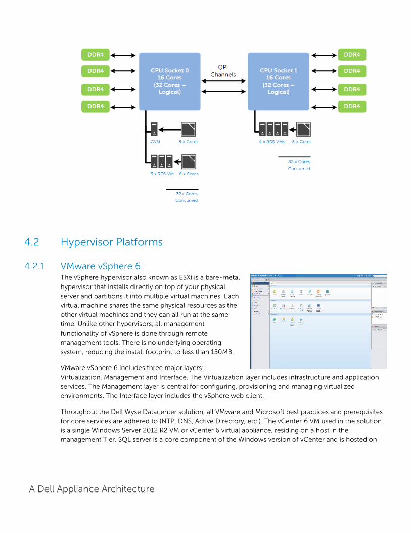
4.1.3.1 NUMA Architecture Considerations Best practices and testing has showed that aligning RDSH design to the physical Non-Uniform Memory
Access (NUMA) architecture of the server CPUs results in increased and optimal performance. NUMA
alignment ensures that a CPU can access its own directly-connected RAM banks faster than those banks
of the adjacent processor which are accessed via the Quick Path Interconnect (QPI). The same is true of
VMs with large vCPU assignments, best performance will be achieved if your VMs receive their vCPU
allotment from a single physical NUMA node. Ensuring that your virtual RDSH servers do not span physical
NUMA nodes will ensure the greatest possible performance benefit.
The general guidance for RDSH NUMA-alignment on the Dell XC appliance is as follows:
4.1.3.2 A5 NUMA Alignment 8 physical cores per CPU in the A5 platform, 16 logical with Hyperthreading active, gives us a total of 32
consumable cores per appliance and falls in line with a 2x oversubscription rate. The Nutanix CVM will
receive its vCPU allotment from the first physical CPU and so configuring the RDSH VMs as shown below
will ensure that no NUMA spanning occurs which could lower performance.
A Dell Appliance Architecture
4.1.3.3 B5 NUMA Alignment 12 physical cores per CPU in the A5 platform, 24 logical with Hyperthreading active, gives us a total of 48
consumable cores per appliance and falls in line with a 2x oversubscription rate. The Nutanix CVM will
receive its vCPU allotment from the first physical CPU and so configuring the RDSH VMs as shown below
will ensure that no NUMA spanning occurs which could lower performance.
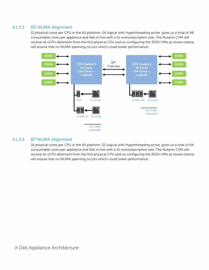
4.1.3.4 B7 NUMA Alignment 16 physical cores per CPU in the A5 platform, 32 logical with Hyperthreading active, gives us a total of 64
consumable cores per appliance and falls in line with a 2x oversubscription rate. The Nutanix CVM will
receive its vCPU allotment from the first physical CPU and so configuring the RDSH VMs as shown below
will ensure that no NUMA spanning occurs which could lower performance.
A Dell Appliance Architecture
4.2 Hypervisor Platforms
VMware vSphere 6 The vSphere hypervisor also known as ESXi is a bare-metal
hypervisor that installs directly on top of your physical
server and partitions it into multiple virtual machines. Each
virtual machine shares the same physical resources as the
other virtual machines and they can all run at the same
time. Unlike other hypervisors, all management
functionality of vSphere is done through remote
management tools. There is no underlying operating
system, reducing the install footprint to less than 150MB.
VMware vSphere 6 includes three major layers:
Virtualization, Management and Interface. The Virtualization layer includes infrastructure and application
services. The Management layer is central for configuring, provisioning and managing virtualized
environments. The Interface layer includes the vSphere web client.
Throughout the Dell Wyse Datacenter solution, all VMware and Microsoft best practices and prerequisites
for core services are adhered to (NTP, DNS, Active Directory, etc.). The vCenter 6 VM used in the solution
is a single Windows Server 2012 R2 VM or vCenter 6 virtual appliance, residing on a host in the
management Tier. SQL server is a core component of the Windows version of vCenter and is hosted on

A Dell Appliance Architecture
another VM also residing in the management Tier. It is recommended that all additional VWorkspace
components be installed in a distributed architecture, one role per server VM.
Microsoft Windows Server 2012 R2 Hyper-V Windows Server 2012 R2 Hyper-V ™ is a powerful virtualization technology that enables businesses to
leverage the benefits of virtualization. Hyper-V reduces
costs, increases hardware utilization, optimizes business
infrastructure, and improves server availability. Hyper-V
works with virtualization-aware hardware to tightly control
the resources available to each virtual machine. The latest
generation of Dell servers includes virtualization-aware
processors and network adapters.
From a network management standpoint, virtual machines
are much easier to manage than physical computers. To
this end, Hyper-V includes many management features
designed to make managing virtual machines simple and
familiar, while enabling easy access to powerful VM-
specific management functions. The primary management platform within a Hyper-V based VWorkspace
virtualization environment is Microsoft Systems Center Virtual Machine Manager SP1 (SCVMM).
SCVMM provides centralized and powerful management, monitoring, and self-service provisioning for
virtual machines. SCVMM host groups are a way to apply policies and to check for problems across several
VMs at once. Groups are organized by owner, operating system, or by custom names such as
“Development” or “Production”. The interface also incorporates Remote Desktop Protocol (RDP); double-
click a VM to bring up the console for that VM—live and accessible from the management console.
A Dell Appliance Architecture
5 Solution Architecture for Wyse vWorkspace
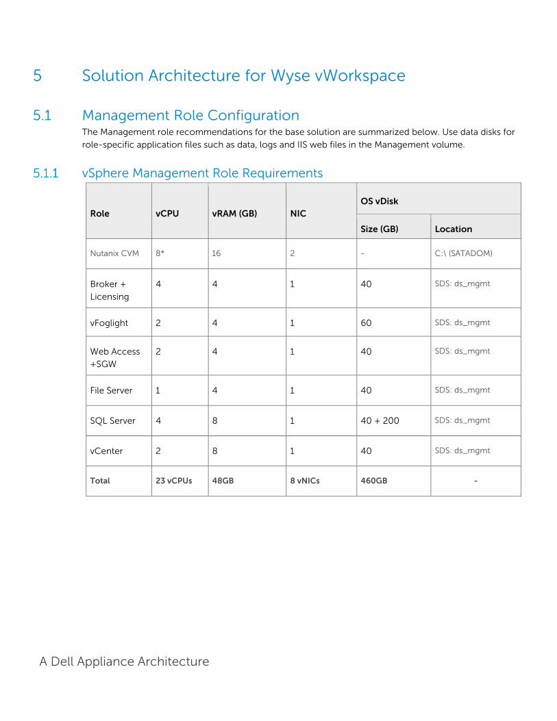
5.1 Management Role Configuration The Management role recommendations for the base solution are summarized below. Use data disks for
role-specific application files such as data, logs and IIS web files in the Management volume.
vSphere Management Role Requirements
Role vCPU vRAM (GB) NIC OS vDisk
Size (GB) Location
Nutanix CVM 8* 16 2 - C:\ (SATADOM)
Broker +
Licensing
4 4 1 40 SDS: ds_mgmt
vFoglight 2 4 1 60 SDS: ds_mgmt
Web Access
+SGW
2 4 1 40 SDS: ds_mgmt
File Server 1 4 1 40 SDS: ds_mgmt
SQL Server 4 8 1 40 + 200 SDS: ds_mgmt
vCenter 2 8 1 40 SDS: ds_mgmt
Total 23 vCPUs 48GB 8 vNICs 460GB -
A Dell Appliance Architecture
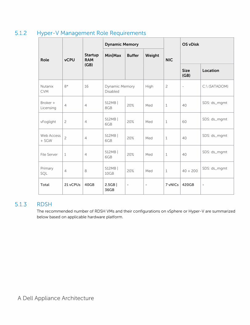
Hyper-V Management Role Requirements
Role vCPU Startup RAM (GB)
Dynamic Memory
NIC
OS vDisk
Min|Max Buffer Weight
Size (GB)
Location
Nutanix
CVM
8* 16 Dynamic Memory
Disabled
High 2 - C:\ (SATADOM)
Broker +
Licensing 4 4
512MB |
8GB 20% Med 1 40
SDS: ds_mgmt
vFoglight 2 4 512MB |
6GB 20% Med 1 60
SDS: ds_mgmt
Web Access
+ SGW 2 4
512MB |
6GB 20% Med 1 40
SDS: ds_mgmt
File Server 1 4 512MB |
6GB 20% Med 1 40
SDS: ds_mgmt
Primary
SQL 4 8
512MB |
10GB 20% Med 1 40 + 200
SDS: ds_mgmt
Total 21 vCPUs 40GB 2.5GB |
36GB
- - 7 vNICs 420GB -
RDSH The recommended number of RDSH VMs and their configurations on vSphere or Hyper-V are summarized
below based on applicable hardware platform.
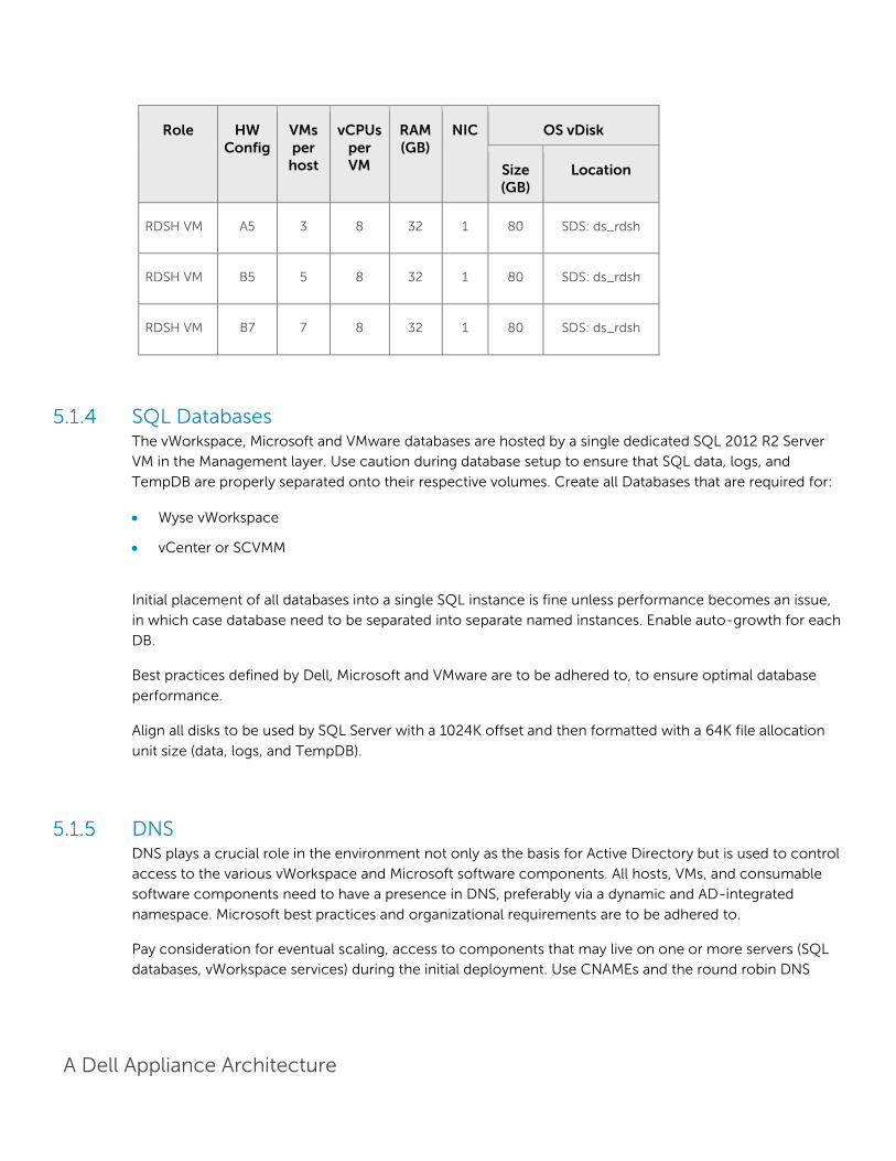
A Dell Appliance Architecture
Role HW Config
VMs per
host
vCPUs per VM
RAM (GB)
NIC OS vDisk
Size (GB)
Location
RDSH VM A5 3 8 32 1 80 SDS: ds_rdsh
RDSH VM B5 5 8 32 1 80 SDS: ds_rdsh
RDSH VM B7 7 8 32 1 80 SDS: ds_rdsh
SQL Databases The vWorkspace, Microsoft and VMware databases are hosted by a single dedicated SQL 2012 R2 Server
VM in the Management layer. Use caution during database setup to ensure that SQL data, logs, and
TempDB are properly separated onto their respective volumes. Create all Databases that are required for:
Wyse vWorkspace
vCenter or SCVMM
Initial placement of all databases into a single SQL instance is fine unless performance becomes an issue,
in which case database need to be separated into separate named instances. Enable auto-growth for each
DB.
Best practices defined by Dell, Microsoft and VMware are to be adhered to, to ensure optimal database
performance.
Align all disks to be used by SQL Server with a 1024K offset and then formatted with a 64K file allocation
unit size (data, logs, and TempDB).
DNS DNS plays a crucial role in the environment not only as the basis for Active Directory but is used to control
access to the various vWorkspace and Microsoft software components. All hosts, VMs, and consumable
software components need to have a presence in DNS, preferably via a dynamic and AD-integrated
namespace. Microsoft best practices and organizational requirements are to be adhered to.
Pay consideration for eventual scaling, access to components that may live on one or more servers (SQL
databases, vWorkspace services) during the initial deployment. Use CNAMEs and the round robin DNS
A Dell Appliance Architecture
mechanism to provide a front-end “mask” to the back-end server actually hosting the service or data
source.
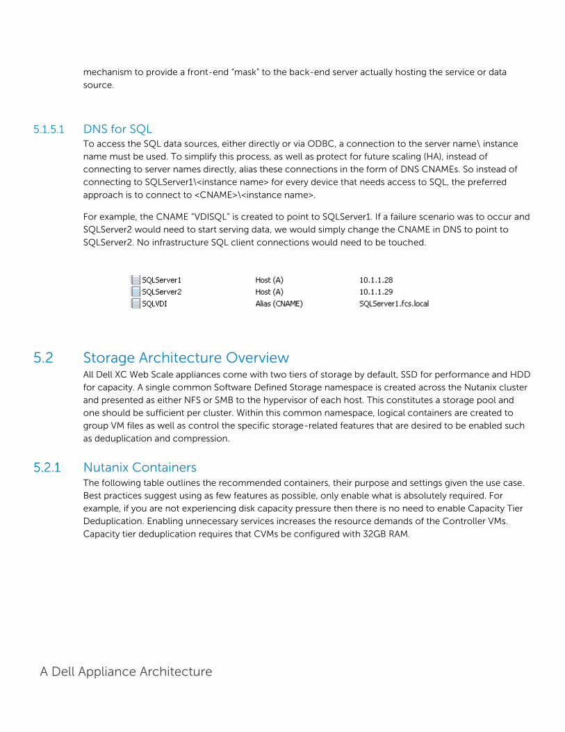
5.1.5.1 DNS for SQL To access the SQL data sources, either directly or via ODBC, a connection to the server name\ instance
name must be used. To simplify this process, as well as protect for future scaling (HA), instead of
connecting to server names directly, alias these connections in the form of DNS CNAMEs. So instead of
connecting to SQLServer1\<instance name> for every device that needs access to SQL, the preferred
approach is to connect to <CNAME>\<instance name>.
For example, the CNAME “VDISQL” is created to point to SQLServer1. If a failure scenario was to occur and
SQLServer2 would need to start serving data, we would simply change the CNAME in DNS to point to
SQLServer2. No infrastructure SQL client connections would need to be touched.
5.2 Storage Architecture Overview All Dell XC Web Scale appliances come with two tiers of storage by default, SSD for performance and HDD
for capacity. A single common Software Defined Storage namespace is created across the Nutanix cluster
and presented as either NFS or SMB to the hypervisor of each host. This constitutes a storage pool and
one should be sufficient per cluster. Within this common namespace, logical containers are created to
group VM files as well as control the specific storage-related features that are desired to be enabled such
as deduplication and compression.
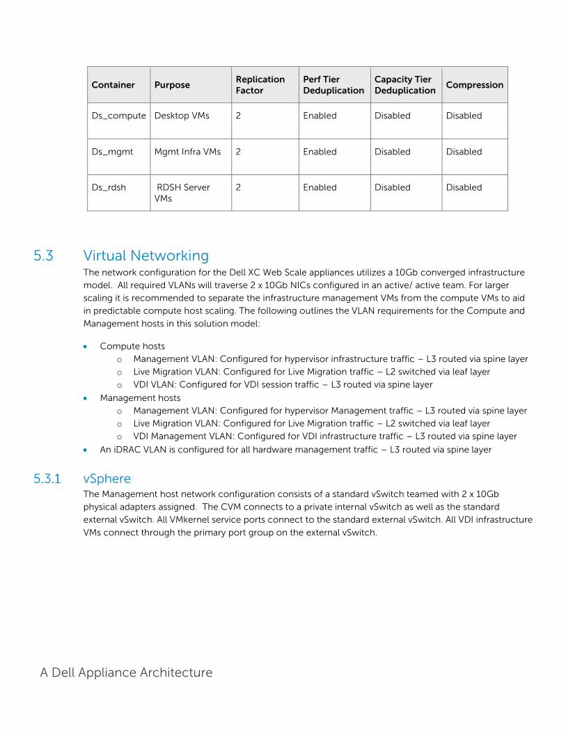
Nutanix Containers The following table outlines the recommended containers, their purpose and settings given the use case.
Best practices suggest using as few features as possible, only enable what is absolutely required. For
example, if you are not experiencing disk capacity pressure then there is no need to enable Capacity Tier
Deduplication. Enabling unnecessary services increases the resource demands of the Controller VMs.
Capacity tier deduplication requires that CVMs be configured with 32GB RAM.
A Dell Appliance Architecture
Container Purpose Replication Factor
Perf Tier Deduplication
Capacity Tier Deduplication
Compression
Ds_compute Desktop VMs 2 Enabled Disabled Disabled
Ds_mgmt Mgmt Infra VMs 2 Enabled Disabled Disabled
Ds_rdsh RDSH Server VMs
2 Enabled Disabled Disabled
5.3 Virtual Networking The network configuration for the Dell XC Web Scale appliances utilizes a 10Gb converged infrastructure
model. All required VLANs will traverse 2 x 10Gb NICs configured in an active/ active team. For larger
scaling it is recommended to separate the infrastructure management VMs from the compute VMs to aid
in predictable compute host scaling. The following outlines the VLAN requirements for the Compute and
Management hosts in this solution model:
Compute hosts
o Management VLAN: Configured for hypervisor infrastructure traffic – L3 routed via spine layer
o Live Migration VLAN: Configured for Live Migration traffic – L2 switched via leaf layer
o VDI VLAN: Configured for VDI session traffic – L3 routed via spine layer
Management hosts
o Management VLAN: Configured for hypervisor Management traffic – L3 routed via spine layer
o Live Migration VLAN: Configured for Live Migration traffic – L2 switched via leaf layer
o VDI Management VLAN: Configured for VDI infrastructure traffic – L3 routed via spine layer
An iDRAC VLAN is configured for all hardware management traffic – L3 routed via spine layer
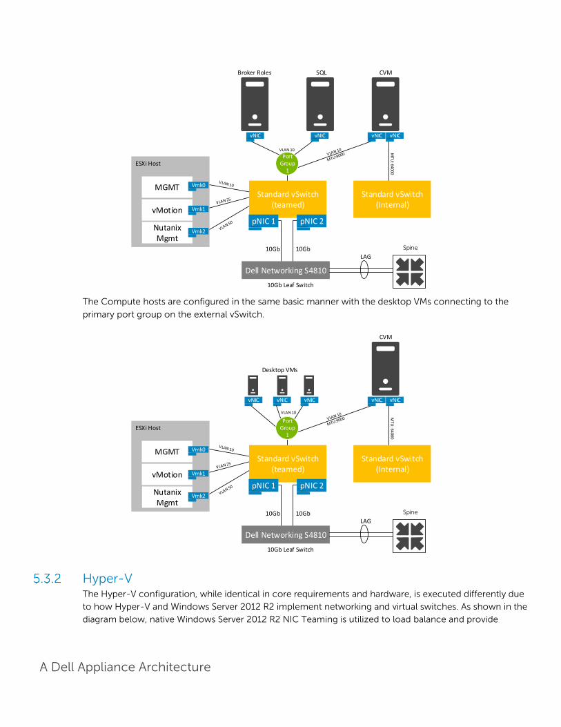
vSphere The Management host network configuration consists of a standard vSwitch teamed with 2 x 10Gb
physical adapters assigned. The CVM connects to a private internal vSwitch as well as the standard
external vSwitch. All VMkernel service ports connect to the standard external vSwitch. All VDI infrastructure
VMs connect through the primary port group on the external vSwitch.
A Dell Appliance Architecture
The Compute hosts are configured in the same basic manner with the desktop VMs connecting to the
primary port group on the external vSwitch.
Hyper-V The Hyper-V configuration, while identical in core requirements and hardware, is executed differently due
to how Hyper-V and Windows Server 2012 R2 implement networking and virtual switches. As shown in the
diagram below, native Windows Server 2012 R2 NIC Teaming is utilized to load balance and provide
10Gb Leaf Switch
VLAN 10
10Gb10Gb
MTU
: 64000
Standard vSwitch(Internal)
Standard vSwitch(teamed)
pNIC 1 pNIC 2
ESXi Host
vMotion
Nutanix Mgmt
MGMT Vmk0
Vmk1
Vmk2
Port Group
1
Dell Networking S4810
Broker Roles
vNICvNIC
SQL CVM
vNIC vNIC
LAG
Spine
10Gb Leaf Switch
VLAN 10
10Gb10Gb
MTU
: 64000
Standard vSwitch(Internal)
Standard vSwitch(teamed)
pNIC 1 pNIC 2
ESXi Host
vMotion
Nutanix Mgmt
MGMT Vmk0
Vmk1
Vmk2
Port Group
1
Dell Networking S4810
CVM
vNIC vNIC
LAG
Spine
Desktop VMs
vNIC vNIC vNIC
A Dell Appliance Architecture
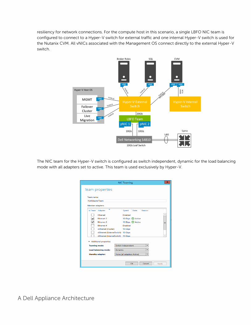
resiliency for network connections. For the compute host in this scenario, a single LBFO NIC team is
configured to connect to a Hyper-V switch for external traffic and one internal Hyper-V switch is used for
the Nutanix CVM. All vNICs associated with the Management OS connect directly to the external Hyper-V
switch.
The NIC team for the Hyper-V switch is configured as switch independent, dynamic for the load balancing
mode with all adapters set to active. This team is used exclusively by Hyper-V.
Broker Roles
10Gb Leaf Switch
20Gb
LBFO Team
pNIC 1 pNIC 2
Hyper-V Host OS
Failover Cluster
Live Migration
MGMT
vNICvNIC
vNIC
vNIC
vNIC
SQL CVM
10Gb10Gb
MTU
: 6
40
00
Hyper-V Internal Switch
Hyper-V External Switch
vNIC vNIC
Dell Networking S4810
LAG
Spine

A Dell Appliance Architecture
The dedicated compute host configuration is shown in the diagram below and configured very similarly to
the management host configuration.
5.4 Scaling Guidance Each component of the solution architecture scales independently according to the desired number of
supported users. Additional appliance nodes can be added at any time to expand the Nutanix SDS pool in a
modular fashion. While there is no scaling limit of the Nutanix architecture itself, practicality might suggest
scaling pods based on the limits of hypervisor clusters (64 nodes for vSphere or Hyper-V). Isolating mgmt
and compute to their own HA clusters provides more flexibility with regard to scaling and functional layer
protection.
10Gb Leaf Switch
VLA
N 20
20Gb
LBFO Team
pNIC 1 pNIC 2
Hyper-V Host OS
Failover Cluster
Live Migration
MGMT
vNIC
vNIC
vNIC
CVM
10Gb10Gb
Hyper-V External Switch
vNIC vNIC
Dell Networking S4810
Desktop VMs
vNIC vNIC vNIC
LAG
Spine
CVM
MTU
: 6
40
00
Hyper-V Internal Switch

A Dell Appliance Architecture
Another option is to design a large single contiguous NDFS namespace with multiple hypervisor clusters
within to provide single pane of glass management. For example, portrayed below is a 30,000 professional
user environment segmented by vSphere HA cluster and broker farm. Each farm compute instance is
segmented into an HA cluster with a hot standby node providing N+1, served by a dedicated pair of mgmt
nodes in a separate HA cluster. This provides multiple broker farms with separated HA protection while
maintaining a single NDFS cluster across all nodes.
The components are scaled either horizontally (by adding additional physical and virtual servers to the
server pools) or vertically (by adding virtual resources to the infrastructure)
Eliminate bandwidth and performance bottlenecks as much as possible
Allow future horizontal and vertical scaling with the objective of reducing the future cost of ownership
of the infrastructure.

A Dell Appliance Architecture
Component Metric Horizontal scalability Vertical scalability
Virtual Desktop Host/Compute Servers
VMs per physical host Additional hosts and clusters added as necessary
Additional RAM or CPU compute power
Broker Servers Desktops per instance (dependent on SQL performance as well)
Additional servers added to the farm
Additional virtual machine resources (RAM and CPU)
RDSH Servers Desktops per instance Additional virtual RDSH servers added to the farm
Additional physical servers to host virtual RDSH servers
Database Services
Concurrent connections, responsiveness of reads/ writes
Migrate databases to a dedicated SQL server and increase the number of management nodes
Additional RAM and CPU for the management nodes
Monitoring Services
Managed agents/units (dependent on SQL performance as well)
Add additional monitoring servers and migrate databases to a dedicated SQL server
Additional RAM and CPU for the management nodes
5.5 Solution High Availability High availability (HA) is offered to protect each architecture solution layer, individually if desired. Following
the N+1 model, additional ToR switches are added to the Network layer and stacked to provide
redundancy as required, additional compute and management hosts are added to their respective layers,
vSphere or Hyper-V clustering is introduced in both the management and compute layers and SQL is
mirrored or clustered. Storage protocol switch stacks and NAS selection will vary based on chosen
solution architecture.
The HA options provide redundancy for all critical components in the stack while improving the
performance and efficiency of the solution as a whole.
Additional switches added to the existing thereby equally spreading each host’s network connections
across multiple switches.
Additional ESXi or Hyper-V hosts added in the compute or mgmt layers to provide N+1 protection.
Applicable vWorkspace infrastructure server roles are duplicated and spread amongst mgmt host
instances where connections to each are load balanced.
SQL Server databases also are protected through the addition and configuration of an "AlwaysOn"
Failover Cluster Instance or Availability Group.

A Dell Appliance Architecture
5.6 Dell Wyse Datacenter for VWorkspace Communication Flow
A Dell Appliance Architecture
6 Solution Performance and Testing
6.1 Load Generation and Monitoring
Login VSI 4 – Login Consultants Login VSI is the de-facto industry standard tool for testing VDI environments and server-based computing
or RDSH environments. It installs a standard collection of desktop application software (e.g. Microsoft
Office, Adobe Acrobat Reader) on each VDI desktop; it then uses launcher systems to connect a specified
number of users to available desktops within the environment. Once the user is connected the workload
is started via a logon script which starts the test script once the user environment is configured by the
login script. Each launcher system can launch connections to a number of ‘target’ machines (i.e. VDI
desktops), with the launchers being managed by a centralized management console, which is used to
configure and manage the Login VSI environment.
VMware vCenter VMware vCenter was used for VMware vSphere-based solutions to gather key data (CPU, Memory and
Network usage) from each of the desktop hosts during each test run. This data was exported to .csv files
for each host and then consolidated to show data from all hosts. While the report does not include
specific performance metrics for the Management host servers, these servers were monitored during
testing and were seen to be performing at an expected performance level.
Microsoft Perfmon Microsoft Perfmon was utilized to collect performance data for tests performed on the Hyper-V platform.
6.2 Performance Analysis Methodology In order to ensure the optimal combination of end-user experience (EUE) and cost-per-user, performance
analysis and characterization (PAAC) on Dell Wyse Datacenter solutions is carried out using a carefully
designed, holistic methodology that monitors both hardware resource utilization parameters and EUE
during load-testing. This methodology is based on the three pillars shown below. Login VSI is currently the
load-testing tool used during PAAC of Dell Wyse Datacenter solutions; Login VSI is the de-facto industry
standard for VDI and server-based computing (SBC) environments and is discussed in more detail below.

A Dell Appliance Architecture
Resource Utilization Poor end-user experience is one of the main risk factors when implementing desktop virtualization but the
root cause for poor end-user experience is resource contention – hardware resources at some point in
the solution have been exhausted, thus causing the poor end-user experience. In order to ensure that this
has not happened (and that it is not close to happening), PAAC on Dell Wyse Datacenter solutions
monitors the relevant resource utilization parameters and applies relatively conservative thresholds as
shown in the table below. As discussed above, these thresholds are carefully selected to deliver an optimal
combination of good end-user experience and cost-per-user, while also providing burst capacity for
seasonal / intermittent spikes in usage. These thresholds are used to decide the number of virtual desktops
(density) that are hosted by a specific hardware environment (i.e. combination of server, storage and
networking) that forms the basis for a Dell Wyse Datacenter RA.
Resource Utilization Thresholds
Parameter Pass / Fail Threshold
Physical Host CPU Utilization 85%
Physical Host Memory Utilization 85%
Network Throughput 85%
Storage IO Latency 20ms

A Dell Appliance Architecture
Dell Wyse Datacenter Workloads and Profiles It’s important to understand user workloads and profiles when designing a desktop virtualization solution
in order to understand the density numbers that the solution can support. At Dell, we use five workload /
profile levels, each of which is bound by specific metrics and capabilities. In addition, we use workloads
and profiles that are targeted at graphics-intensive use cases. We present more detailed information in
relation to these workloads and profiles below but first it is useful to define the terms “workload” and
“profile” as they are used in this document.
Profile: This is the configuration of the virtual desktop - number of vCPUs and amount of RAM
configured on the desktop (i.e. available to the user).
Workload: This is the set of applications used by performance analysis and characterization (PAAC) of
Dell Wyse Datacenter solutions e.g. Microsoft Office applications, PDF Reader, Internet Explorer etc.
User Profile vCPUs Physical Memory
Hyper-V Minimum Memory
Hyper-V Max Memory
ESXi Memory Reservation
Memory Configured
OS
Standard 1 2GB 1GB 2GB 1GB 2GB x86
Enhanced 2 3GB 1GB 3GB 1.5GB 3GB x86
Professional 2 4GB 1GB 4GB 2GB 4GB x64
Dell Wyse Datacenter Workloads Load-testing on each of the profiles described in the above table is carried out using an appropriate
workload that is representative of the relevant use case. In the case of the non-graphics workloads, these
workloads are Login VSI workloads and in the case of graphics workloads, these are specially designed
workloads that stress the VDI environment to a level that is appropriate for the relevant use case. This
information is summarized in the table below:

A Dell Appliance Architecture
Profile Name Workload OS Image
Standard Login VSI Light Shared
Enhanced Login VSI Medium Shared
Professional Login VSI Heavy Shared + Profile Virtualization
Graphics eFigures / AutoCAD - SPEC Viewperf
Persistent
Further information for each of the workloads is given below. It is noted that for Login VSI testing, the
following login and boot paradigm is used:
For single-server / single-host testing (typically carried out to determine the virtual desktop capacity of
a specific physical server), users are logged in every 30 seconds.
For multi-host / full solution testing, users are logged in over a period of 1-hour, to replicate the normal
login storm in an enterprise environment.
All desktops are pre-booted in advance of logins commencing.
For all testing, all virtual desktops run an industry-standard anti-virus solution (currently McAfee
VirusScan Enterprise) in order to fully replicate a customer environment.
6.2.3.1 Login VSI Light Workload Compared to the Login VSI medium workload described below, the light workload runs fewer applications
(mainly Excel and Internet Explorer with some minimal Word activity) and starts/stops the applications less
frequently. This results in lower CPU, memory and disk IO usage.
6.2.3.2 Login VSI Medium Workload
The Login VSI medium workload is designed to run on 2vCPU’s per desktop VM. This workload emulates a
medium knowledge worker using Office, IE, PDF and Java/FreeMind. The Login VSI medium workload has
the following characteristics
Once a session has been started the workload will repeat (loop) every 48 minutes.
The loop is divided in four segments; each consecutive Login VSI user logon will start a different segment. This ensures that all elements in the workload are equally used throughout the test.
The medium workload opens up to five applications simultaneously.
The keyboard type rate is 160 ms for each character.
Approximately two minutes of idle time is included to simulate real-‐world users.

A Dell Appliance Architecture
Each loop opens and uses:
Outlook, browse messages.
Internet Explorer, browse different webpages and a YouTube style video (480p movie trailer) is opened three times in every loop.
Word, one instance to measure response time, one instance to review and edit a document.
Doro PDF Printer & Acrobat Reader, the Word document is printed and exported to PDF.
Excel, a very large randomized sheet is opened.
PowerPoint, a presentation is reviewed and edited.
FreeMind, a Java based Mind Mapping application.
6.2.3.3 Login VSI Heavy Workload
The heavy workload is based on the medium workload except that the heavy workload:
Begins by opening four instances of Internet Explorer. These instances stay open throughout the
workload loop.
Begins by opening two instances of Adobe Reader. These instances stay open throughout the
workload loop.
There are more PDF printer actions in the workload.
Instead of 480p videos a 720p and a 1080p video are watched.
Increased the time the workload plays a flash game.
The idle time is reduced to two minutes.
6.3 Testing and Validation
Testing Process The purpose of the single server testing is to validate the architectural assumptions made around the
server stack. Each user load is tested against four runs. A pilot run is conducted to validate that the
infrastructure is functioning and valid data is captured. Subsequently three more runs are conducted
allowing for correlation of data. Summary of the test results is listed out in the below mentioned tabular
format.
At different stages of the testing the testing team will complete some manual “User Experience” Testing
while the environment is under load. This will involve a team member logging into a session during the run
and completing tasks similar to the User Workload description. While this experience is subjective, it will
help provide a better understanding of the end user experience of the desktop sessions, particularly under
high load, and ensure that the data gathered is reliable.
Login VSI has two modes for launching user’s sessions:
Parallel

A Dell Appliance Architecture
Sessions are launched from multiple launcher hosts in a round robin fashion; this mode is recommended
by Login Consultants when running tests against multiple host servers. In parallel mode the VSI console is
configured to launch a number of sessions over a specified time period (specified in seconds)
Sequential
Sessions are launched from each launcher host in sequence, sessions are only started from a second host
once all sessions have been launched on the first host and this is repeated for each launcher host.
Sequential launching is recommended by Login Consultants when testing a single desktop host server.
The VSI console is configure to launch a specified number of session at a specified interval specified in
seconds
All test runs which involved the six desktop hosts were conducted using the Login VSI “Parallel Launch”
mode and all sessions were launched over an hour to try and represent the typical 9am logon storm.
Once the last user session has connected, the sessions are left to run for 15 minutes prior to the sessions
being instructed to logout at the end of the current task sequence, this allows every user to complete a
minimum of two task sequences within the run before logging out. The single server test runs were
configured to launch user sessions every 60 seconds, as with the full bundle test runs sessions were left to
run for 15 minutes after the last user connected prior to the sessions being instructed to log out.
6.4 vWorkspace Test Results The following results represent 300 Premium workload users on a 3 node Nutanix cluster. One host was
dedicated to Management while the remaining two hosts each delivered 150 Virtual Desktops.
Below is the configuration of the compute hosts used for this testing.
1GB networking was used for the deployment of the Bensen XC appliances while all 10GB networking was
used for the PAAC testing.
Platform Config CPU Memory RAID Ctlr HD Config Network Login VSI Workload
XC630 B7 E5-2698v3 (16Core, 2.3GHz)
384GB H730P 1 X 64 GB
SATADOM
(CVM/ HV)
2 x 10Gb,
2 x 1Gb
SFP+/ BT
Heavy
2 x 400GB, Intel
S3700, SATA
SSD‘s 2.5” (T1)
8 x 1TB NL SAS 2.5” (T2)

A Dell Appliance Architecture
Compute and Management resources were split out with the following configuration across a three node
Nutanix cluster and all test runs were completed with this configuration.
Node3 – XC630– Dedicated Management (vWorkspace Broker, SQL Server & File Services)
Node2 – XC630 – Dedicated Compute
Node1 – XC630 – Dedicated Compute
Please refer to Section 5.1 for the configuration of each management virtual machine.
The virtual machines were non-persistent vWorkspace desktops each configured on Windows 8.1 aligning
with the Login VSI 4.X virtual machine configuration, Office2010 was used with each Virtual Machine sized
at 25GB. User Workload configuration of the load generation virtual machines is shown in the table below.
The virtual machines were non-persistent linked clone desktops each configured on Windows 8.1 aligning
with the Login VSI 4.X virtual machine configuration, Office 2010 was used with each Virtual Machine sized
at 32 GB. User Workload configuration of the load generation virtual machines is shown in the table
below.
User Workload vCPUs Memory OS Bit Level HD Size GB
Professional User 2 4GB x64 32
The RDSH environment was configured as shown in the table below for each host according to platform.
The RDSH images were built using Windows Server 2012 R2 Standard edition and Microsoft Office 2010
plus the support tools required for Login VSI testing.
Role Config vCPU Startup RAM
Dynamic Memory NIC
OS vDisk
Min|Max Buffer Weight Size(GB) Location
VM B7 2 1GB 1024MB | 4GB
20% Med 1 25 SDS: ds_compute
Role Config VMs per host vCPUs RAM (GB) NIC Disk Size GB
RDSH VMs B7 5 8 32 1 80

A Dell Appliance Architecture
6.4.1.1 vWorkspace, Heavy Workload – B7 Validation was performed using CCC standard testing methodology using LoginVSI 4 load generation tool
for VDI benchmarking that simulates production user workloads. Dedupe on the performance Tier was
turned on for this testing.
Each test run adhered to PAAC best practices with a 30 second session logon interval, 16 minutes of
steady state after which sessions would begin logging off.
The following table summarizes the test results for the various workloads and configurations:
Hyper-
visor Provisioning Workload
Density
Per Host
Peak
CPU
%
Avg Memory
Consumed
Avg
IOPS/U
ser
Avg Net
Kbps/User
Hyper-V vWorkspace Professional 155 75% 249 GB 7.45 666
CPU Utilization* CPU % for Hyper-V Hosts was adjusted to account for the fact that on Intel E5-2698v3
series processors the ESX host CPU metrics will exceed the rated 100% for the host if Turbo Boost is
enabled (by default). The Adjusted CPU % Usage is based on 100% usage and but is not reflected in the
charts. The figure shown in the table is the Compute host steady state peak CPU Usage. One Nutanix CVM
Controller virtual machine is located on each node and is allocated 10000MHz of CPU reservation.
Memory utilization. The figure shown in the table above is the average memory consumed per Compute
host over the recorded test period.
The IOPS results are calculated from the average Nutanix Cluster Disk IOPS figure over the test period
divided by the number of users.
Network Utilization The figure shown in the table is the average Kilobits/sec/User per Compute host
over the recorded test period.
6.4.1.2 Performance Results The architecture for this solution includes a dedicated management host and two compute hosts. Each of
the compute hosts was populated with 70 full virtual machines and one Nutanix CVM per host.
The Nutanix CVM’s took up approximately 12% of the compute hosts CPU Usage at the start of the test
run.
This chart does not include the additional 10% of CPU available from the Turbo boost feature. With Turbo
Boost included an additional 10% CPU is available for us.

A Dell Appliance Architecture
The below graph shows the performance data for 150 user sessions per host on a pair of Compute hosts.
The CPU reaches a steady state peak of 75% during the test cycle when approximately 150 users are
logged on to each compute host.
The Management host in the cluster runs the Cluster Shared Volume and vWorkspace management virtual
machines and a Nutanix CVM virtual machine. Its CPU utilization is significantly lower than the compute
hosts in the cluster. The CPU utilization for the management host does not exceed 10% at any point in the
test cycle.
Memory consumption for the cluster, out of a total of 384 GB available memory per node there were no
constraints for any of the hosts. The Compute Hosts reached a max memory consumption of 249 GB. This
graph illustrates the level of available memory throughout the test cycle.
0
10
20
30
40
50
60
70
80 1
2:4
4:1
6.9
71
12
:51
:46
.96
1
12
:59
:16
.96
4
13
:06
:46
.96
5
13
:14
:16
.96
5
13
:21
:46
.96
6
13
:29
:16
.96
6
13
:36
:46
.96
7
13
:44
:16
.96
8
13
:51
:46
.96
8
13
:59
:16
.96
9
14
:06
:46
.97
0
14
:14
:16
.97
0
14
:21
:46
.97
1
14
:29
:16
.96
2
14
:36
:46
.95
5
14
:44
:16
.94
9
Compute Host 1
Compute Host 2
Total CPU Utilization (%Run Time)

A Dell Appliance Architecture
Dual port 10Gb Networking was used for the hosts. The graph below shows the utilization for each
compute host in the cluster.
The following graphs show the storage utilization for the Nutanix Cluster. These graphs are taken from
Prism. The below graph shows the Nutanix Controller CPU and Memory utilization. Neither exceeded 50%
of the allocated resources.
0
50000
100000
150000
200000
250000
300000
350000
400000
450000
12
:43
:46
.95
5
12
:50
:46
.95
8
12
:57
:46
.96
4
13
:04
:46
.96
4
13
:11
:46
.96
5
13
:18
:46
.96
6 1
3:2
5:4
6.9
66
13
:32
:46
.96
7
13
:39
:46
.96
7
13
:46
:46
.96
8
13
:53
:46
.96
9
14
:00
:46
.96
9
14
:07
:46
.97
0
14
:14
:46
.97
2
14
:21
:46
.97
1
14
:28
:46
.96
1
14
:35
:46
.95
5
14
:42
:46
.96
3
Compute Host 1
Compute Host 2
Total Memory
Memory Utilization (Bytes per/Sec)
0
50000000
100000000
150000000
200000000
250000000
12
:43
:46
.95
5
12
:49
:46
.96
8
12
:55
:46
.96
1
13
:01
:46
.96
4
13
:07
:46
.96
5
13
:13
:46
.96
5
13
:19
:46
.96
6
13
:25
:46
.96
6
13
:31
:46
.96
7
13
:37
:46
.96
7
13
:43
:46
.96
8
13
:49
:46
.96
8
13
:55
:46
.96
9
14
:01
:46
.96
9
14
:07
:46
.97
0
14
:13
:46
.97
0
14
:19
:46
.97
1
14
:25
:46
.96
9
14
:31
:46
.95
7
14
:37
:46
.96
0
14
:43
:46
.94
9
Compute Host 1
Compute Host 2
Compute Host 1 Network Utilization (Bytes Total/sec)

A Dell Appliance Architecture
The following graph shows the IOPS recorded by the Nutanix file system at peak of the test. This figure is
2237IOPS.
Next we look at the Network utilization at peak of the test. The utilization did not exceed 100Mb/ps.

A Dell Appliance Architecture
In Summary, the performance of the solution under test was very good. CPU utilization at 75% indicates
that additional virtual machines could be added to each compute node. Memory utilization peaked at 249
GB running the premium workload on compute nodes; on the Nutanix cluster the system memory
utilization was low at 50% of the available memory. Subjective user test was excellent with no delay or
grab experienced. Accessing media content was quick with no delay in the video stream.
6.4.1.3 vWorkspace/ RDSH, Standard Workload – B7 Validation was performed using CCC standard testing methodology using LoginVSI 4 load generation tool
for VDI benchmarking that simulates production user workloads. Dedupe on the performance Tier was
turned on for this testing.
Each test run adhered to PAAC best practices with a 30 second session logon interval, 16 minutes of
steady state after which sessions would begin logging off.
The following table summarizes the test results for the various workloads and configurations:
Hyper-
Visor Provisioning Workload
Density
Per Host
Peak
CPU
%
Avg
Memory
Consumed
Avg
IOPS/U
ser
Avg Net
Kbps/User
Hyper-V vWorkspace
Session Hosts
Standard 250 80% 180 GB 2.2 601
CPU Utilization* CPU % for Hyper-V Hosts should be adjusted to account for the fact that on Intel E5-
2698v3 series processors the ESX host CPU metrics will exceed the rated 100% for the host if Turbo Boost

A Dell Appliance Architecture
is enabled (by default). The Adjusted CPU % Usage is based on 100% usage and but is not reflected in the
charts. The figure shown in the table is the Compute host steady state peak CPU Usage. One Nutanix CVM
Controller virtual machine is located on each node and is allocated 10000MHz of CPU reservation.
Memory utilization. The figure shown in the table above is the average memory consumed per Compute
host over the recorded test period.
The IOPS results are calculated from the average Nutanix Cluster Disk IOPS figure over the test period
divided by the number of users.
Network Utilization The figure shown in the table is the average Kilobits/sec/User per Compute host
over the recorded test period.
6.4.1.4 Performance Results The architecture for this solution includes a dedicated management host and two compute hosts. Each of
the compute hosts was populated with 7 Server 2012 R2 Session hosts and one Nutanix CVM per host.
The Nutanix CVM’s took up less than 10% of the compute hosts CPU Usage at the start of the test run.
This chart does not include the additional 10% of CPU available from the Turbo boost feature. With Turbo
Boost included an additional 10% CPU is available for us.
The below graph shows the performance data for 250 user sessions per host on a pair of Compute hosts.
The CPU reaches a steady state peak of 80% during the test cycle when approximately 250 users are
logged on to each compute host.
A total of 520 sessions were launched to log in 500 users. 486 sessions went active during the test and
482 sessions logged out.
0
1020
30
4050
60708090
1:2
3:4
3 A
M
1:2
7:1
3 A
M
1:3
0:4
3 A
M
1:3
4:1
3 A
M
1:3
7:4
3 A
M
1:4
1:1
3 A
M
1:4
4:4
3 A
M
1:4
8:1
3 A
M
1:5
1:4
3 A
M
1:5
5:1
3 A
M
1:5
8:4
3 A
M
2:0
2:1
3 A
M
2:0
5:4
3 A
M
2:0
9:1
3 A
M
2:1
2:4
3 A
M
2:1
6:1
3 A
M
2:1
9:4
3 A
M
2:2
3:1
3 A
M
2:2
6:4
3 A
M
2:3
0:1
3 A
M
2:3
3:4
3 A
M
2:3
7:1
3 A
M
2:4
0:4
3 A
M
2:4
4:1
3 A
M
2:4
7:4
3 A
M
2:5
1:1
3 A
M
2:5
4:4
3 A
M
Compute Host CPU (% Total Run Time)
Compute Host 1 Compute Host 2

A Dell Appliance Architecture
The Management host in the cluster runs the Cluster Shared Volume and vWorkspace management virtual
machines and a Nutanix CVM virtual machine. Its CPU utilization is significantly lower than the compute
hosts in the cluster. The CPU utilization for the management host does not exceed 10% at any point in the
test cycle.
Memory consumption for the cluster, out of a total of 384 GB available memory per node there were no
constraints for any of the hosts. Each host consumed circa 136GB of physical memory on average. Peak
consumption during the log off period was 180GB.
Dual port 10Gb Networking was used for the hosts. The below graph shows the utilization for each
compute host in the cluster.
020000400006000080000
100000120000140000160000180000200000
1:2
3:4
3 A
M
1:2
7:1
3 A
M
1:3
0:4
3 A
M
1:3
4:1
3 A
M
1:3
7:4
3 A
M
1:4
1:1
3 A
M
1:4
4:4
3 A
M
1:4
8:1
3 A
M
1:5
1:4
3 A
M
1:5
5:1
3 A
M
1:5
8:4
3 A
M
2:0
2:1
3 A
M
2:0
5:4
3 A
M
2:0
9:1
3 A
M
2:1
2:4
3 A
M
2:1
6:1
3 A
M
2:1
9:4
3 A
M
2:2
3:1
3 A
M
2:2
6:4
3 A
M
2:3
0:1
3 A
M
2:3
3:4
3 A
M
2:3
7:1
3 A
M
2:4
0:4
3 A
M
2:4
4:1
3 A
M
2:4
7:4
3 A
M
2:5
1:1
3 A
M
2:5
4:4
3 A
M
Compute Host Memory Utilization
Compute Host 1 Active Compute Host 2 Active
Compute Host 1 Consumed Compute Host 2 Consumed
0
10000000
20000000
30000000
40000000
50000000
60000000
1:2
4:1
3 A
M
1:2
7:4
3 A
M
1:3
1:1
3 A
M
1:3
4:4
3 A
M
1:3
8:1
3 A
M
1:4
1:4
3 A
M
1:4
5:1
3 A
M
1:4
8:4
3 A
M
1:5
2:1
3 A
M
1:5
5:4
3 A
M
1:5
9:1
3 A
M
2:0
2:4
3 A
M
2:0
6:1
3 A
M
2:0
9:4
3 A
M
2:1
3:1
3 A
M
2:1
6:4
3 A
M
2:2
0:1
3 A
M
2:2
3:4
3 A
M
2:2
7:1
3 A
M
2:3
0:4
3 A
M
2:3
4:1
3 A
M
2:3
7:4
3 A
M
2:4
1:1
3 A
M
2:4
4:4
3 A
M
2:4
8:1
3 A
M
2:5
1:4
3 A
M
Network Utilization (Bytes Per Sec.)
Compute Host 1 Compute Host 2
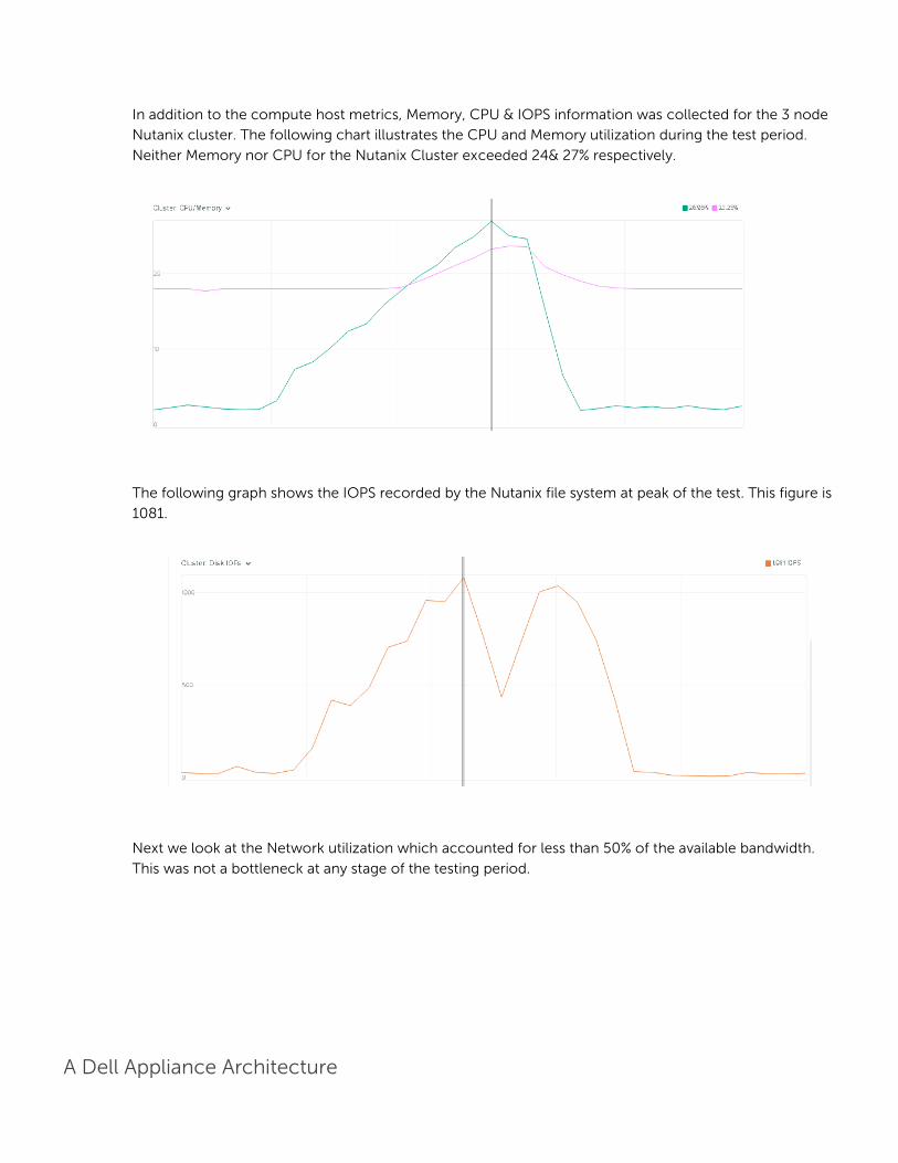
A Dell Appliance Architecture
In addition to the compute host metrics, Memory, CPU & IOPS information was collected for the 3 node
Nutanix cluster. The following chart illustrates the CPU and Memory utilization during the test period.
Neither Memory nor CPU for the Nutanix Cluster exceeded 24& 27% respectively.
The following graph shows the IOPS recorded by the Nutanix file system at peak of the test. This figure is
1081.
Next we look at the Network utilization which accounted for less than 50% of the available bandwidth.
This was not a bottleneck at any stage of the testing period.
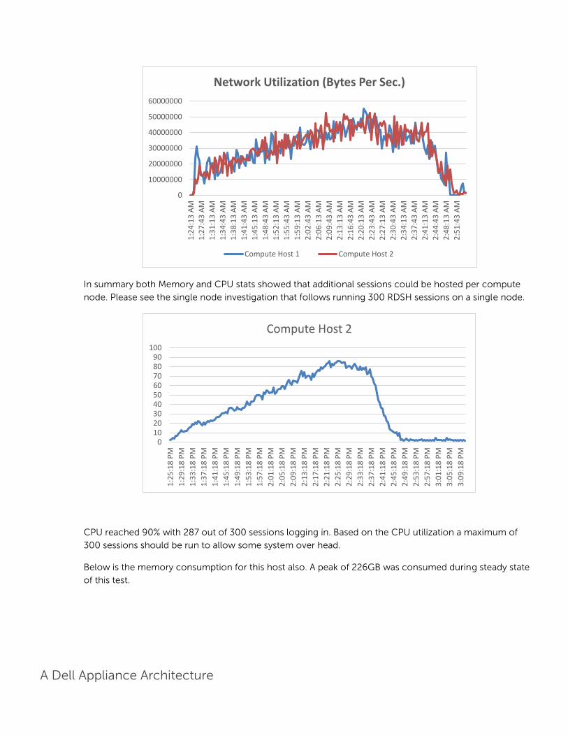
A Dell Appliance Architecture
In summary both Memory and CPU stats showed that additional sessions could be hosted per compute
node. Please see the single node investigation that follows running 300 RDSH sessions on a single node.
CPU reached 90% with 287 out of 300 sessions logging in. Based on the CPU utilization a maximum of
300 sessions should be run to allow some system over head.
Below is the memory consumption for this host also. A peak of 226GB was consumed during steady state
of this test.
0
10000000
20000000
30000000
40000000
50000000
60000000
1:2
4:1
3 A
M
1:2
7:4
3 A
M
1:3
1:1
3 A
M
1:3
4:4
3 A
M
1:3
8:1
3 A
M
1:4
1:4
3 A
M
1:4
5:1
3 A
M
1:4
8:4
3 A
M
1:5
2:1
3 A
M
1:5
5:4
3 A
M
1:5
9:1
3 A
M
2:0
2:4
3 A
M
2:0
6:1
3 A
M
2:0
9:4
3 A
M
2:1
3:1
3 A
M
2:1
6:4
3 A
M
2:2
0:1
3 A
M
2:2
3:4
3 A
M
2:2
7:1
3 A
M
2:3
0:4
3 A
M
2:3
4:1
3 A
M
2:3
7:4
3 A
M
2:4
1:1
3 A
M
2:4
4:4
3 A
M
2:4
8:1
3 A
M
2:5
1:4
3 A
M
Network Utilization (Bytes Per Sec.)
Compute Host 1 Compute Host 2
0102030405060708090
100
1:2
5:1
8 P
M
1:2
9:1
8 P
M
1:3
3:1
8 P
M
1:3
7:1
8 P
M
1:4
1:1
8 P
M
1:4
5:1
8 P
M
1:4
9:1
8 P
M
1:5
3:1
8 P
M
1:5
7:1
8 P
M
2:0
1:1
8 P
M
2:0
5:1
8 P
M
2:0
9:1
8 P
M
2:1
3:1
8 P
M
2:1
7:1
8 P
M
2:2
1:1
8 P
M
2:2
5:1
8 P
M
2:2
9:1
8 P
M
2:3
3:1
8 P
M
2:3
7:1
8 P
M
2:4
1:1
8 P
M
2:4
5:1
8 P
M
2:4
9:1
8 P
M
2:5
3:1
8 P
M
2:5
7:1
8 P
M
3:0
1:1
8 P
M
3:0
5:1
8 P
M
3:0
9:1
8 P
M
Compute Host 2

A Dell Appliance Architecture
Finally, we look at Network Utilization which showed no strain on the network at any time.
Analysis of the Nutanix File system showed 50% network utilization while both CPU and Memory
consumption were low as expected.
0
50000
100000
150000
200000
250000
1:2
4:4
8 P
M
1:2
8:4
8 P
M
1:3
2:4
8 P
M
1:3
6:4
8 P
M
1:4
0:4
8 P
M
1:4
4:4
8 P
M
1:4
8:4
8 P
M
1:5
2:4
8 P
M
1:5
6:4
8 P
M
2:0
0:4
8 P
M
2:0
4:4
8 P
M
2:0
8:4
8 P
M
2:1
2:4
8 P
M
2:1
6:4
8 P
M
2:2
0:4
8 P
M
2:2
4:4
8 P
M
2:2
8:4
8 P
M
2:3
2:4
8 P
M
2:3
6:4
8 P
M
2:4
0:4
8 P
M
2:4
4:4
8 P
M
2:4
8:4
8 P
M
2:5
2:4
8 P
M
2:5
6:4
8 P
M
3:0
0:4
8 P
M
3:0
4:4
8 P
M
3:0
8:4
8 P
M
Compute Host 2 Consumed Memory
0
50000000
100000000
150000000
200000000
250000000
1:2
5:1
8 P
M
1:2
9:4
8 P
M
1:3
4:1
8 P
M
1:3
8:4
8 P
M
1:4
3:1
8 P
M
1:4
7:4
8 P
M
1:5
2:1
8 P
M
1:5
6:4
8 P
M
2:0
1:1
8 P
M
2:0
5:4
8 P
M
2:1
0:1
8 P
M
2:1
4:4
8 P
M
2:1
9:1
8 P
M
2:2
3:4
8 P
M
2:2
8:1
8 P
M
2:3
2:4
8 P
M
2:3
7:1
8 P
M
2:4
1:4
8 P
M
2:4
6:1
8 P
M
2:5
0:4
8 P
M
2:5
5:1
8 P
M
2:5
9:4
8 P
M
3:0
4:1
8 P
M
3:0
8:4
8 P
M
Compute Host 2 Network utilization (Bytes Total/sec)

A Dell Appliance Architecture
In summary, the single node running 300 sessions showed that Network utilization was high on the
Nutanix cluster but did not impact the user performance. User experience was good for each session and
a user subjective test showed good performance.

A Dell Appliance Architecture
Acknowledgements
Thank you to the Nutanix Technical Marketing team for the detail presented in section 2.2 of this document.

A Dell Appliance Architecture
About the Authors
Peter Fine is the Sr. Principal Solutions Architect for enterprise VDI solutions at Dell. Peter has extensive
experience and expertise on the broader Microsoft, Citrix and VMware solutions software stacks as well as
in enterprise virtualization, storage, networking and enterprise data center design.
Andrew Breedy is a Solution Engineer working in the Dell-Wyse Datacenter engineering group. Andrew
has extensive experience in server hardware and on Microsoft and VMWare virtualization solutions as well
as a background in engineering test processes and performance analysis and characterization.
Jerry Van Blaricom is a Systems Principal Engineer in the Desktop Virtualization Solutions Group at Dell.
Jerry has extensive experience with the design and implementation of a broad range of enterprise systems
and is focused on making Dell’s virtualization offerings consistently best in class.
Rick Biedler is the Solutions Development Manager for Datacenter appliances at Dell, managing the
development and delivery of Enterprise class Desktop virtualization solutions based on Dell datacenter
components and core virtualization platforms.
Manish Chacko is the Sr. Technical Marketing Advisor for VDI-based solutions at Dell. Before writing about
technology, Manish has spent time designing, implementing and supporting technology- in IT, Systems
Engineering & Network Performance & Monitoring. Manish has been a long-time Dell customer &
Advocate before becoming a Dell employee.