Embed Size (px)
Citation preview

Dell EMC PowerVault ME4 Series Storage System Owner’s Manual

Notes, cautions, and warnings
NOTE: A NOTE indicates important information that helps you make better use of your product.
CAUTION: A CAUTION indicates either potential damage to hardware or loss of data and tells you how to avoid the
problem.
WARNING: A WARNING indicates a potential for property damage, personal injury, or death.
© 2018 – 2019 Dell Inc. or its subsidiaries. All rights reserved. Dell, EMC, and other trademarks are trademarks of Dell Inc. or its subsidiaries. Other trademarks may be trademarks of their respective owners.
2019 - 12
Rev. A05

1 Storage system hardware..............................................................................................................5Locate the service tag.......................................................................................................................................................... 5Enclosure configurations...................................................................................................................................................... 5
Upgrading to dual-controller configuration.................................................................................................................. 6Removing the second controller....................................................................................................................................6
Enclosure management........................................................................................................................................................ 6Operation................................................................................................................................................................................ 7
Attach or remove the front bezel of a 2U enclosure.................................................................................................. 9Enclosure variants................................................................................................................................................................. 92U enclosure core product................................................................................................................................................. 10
2U enclosure front panel................................................................................................................................................ 112U enclosure rear panel..................................................................................................................................................11
5U84 enclosure core product............................................................................................................................................. 145U84 enclosure front panel...........................................................................................................................................145U84 enclosure rear panel............................................................................................................................................ 15
5U84 enclosure chassis....................................................................................................................................................... 185U84 enclosure drawers................................................................................................................................................18
Operator's (Ops) panel LEDs............................................................................................................................................. 192U enclosure Ops panel.................................................................................................................................................195U enclosure Ops panel................................................................................................................................................20Controller modules......................................................................................................................................................... 21
CompactFlash...................................................................................................................................................................... 26Supercapacitor pack......................................................................................................................................................27
Controller failure when a single-controller is operational................................................................................................27Transporting cache........................................................................................................................................................27
2 Troubleshooting and problem solving........................................................................................... 28Overview.............................................................................................................................................................................. 28Fault isolation methodology................................................................................................................................................28
Fault isolation methodology basic steps..................................................................................................................... 28Options available for performing basic steps............................................................................................................. 28Performing basic steps................................................................................................................................................. 29
LEDs......................................................................................................................................................................................302U enclosure LEDs......................................................................................................................................................... 315U84 enclosure LEDs....................................................................................................................................................33
Troubleshooting 2U enclosures......................................................................................................................................... 35PCM faults......................................................................................................................................................................36Thermal monitoring and control...................................................................................................................................36Thermal alarm.................................................................................................................................................................37
Troubleshooting 5U enclosures......................................................................................................................................... 37Thermal considerations.................................................................................................................................................38CLI port connections.....................................................................................................................................................38
Temperature sensors.......................................................................................................................................................... 38Host I/O................................................................................................................................................................................38
Contents
Contents 3

3 Module removal and replacement.................................................................................................39ESD precautions.................................................................................................................................................................. 39Dealing with hardware faults..............................................................................................................................................39Firmware updates................................................................................................................................................................40
Configuring partner firmware update......................................................................................................................... 40Continuous operation during replacement....................................................................................................................... 40Shutting down attached hosts.......................................................................................................................................... 40Shutting down a controller module................................................................................................................................... 40
Using the PowerVault Manager...................................................................................................................................40Using the CLI...................................................................................................................................................................41
Verifying component failure................................................................................................................................................41Customer-replaceable units (CRUs)..................................................................................................................................41
Attach or remove the front bezel of a 2U enclosure................................................................................................ 42Replacing a drive carrier module in a 2U enclosure...................................................................................................42Replacing a DDIC in a 5U enclosure............................................................................................................................ 47Replacing a controller module or IOM in a 2U or 5U enclosure...............................................................................56Replacing a power supply unit (PSU) in a 5U enclosure..........................................................................................60Replacing a fan cooling module (FCM) in a 5U enclosure........................................................................................ 61Replacing a power cooling module (PCM) in a 2U enclosure..................................................................................62Completing the component installation process....................................................................................................... 64
Verifying component operation......................................................................................................................................... 64Using LEDs..................................................................................................................................................................... 65Using management interfaces..................................................................................................................................... 65
Performing updates in PowerVault Manager after replacing an FC or SAS HBA...................................................... 65
4 Events and event messages.........................................................................................................67Event descriptions...............................................................................................................................................................67Events................................................................................................................................................................................... 67Events (continued).............................................................................................................................................................101Events (continued)............................................................................................................................................................ 120Removed events................................................................................................................................................................ 138Events sent as indications to SMI-S clients................................................................................................................... 138Using the trust command................................................................................................................................................. 138
A Connecting to the CLI port using a serial cable............................................................................ 140Mini-USB Device Connection............................................................................................................................................141
Microsoft Windows drivers......................................................................................................................................... 142Linux drivers..................................................................................................................................................................142
B Technical specifications............................................................................................................ 143
C Standards and regulations......................................................................................................... 147
4 Contents

Storage system hardwareThis chapter describes the front-end and back-end components of ME4 Series enclosures.
Some of the modules within the enclosure are replaceable as described in Module removal and replacement. The types of modules and other components that can be replaced are defined below:
• CRU: Customer-replaceable Unit• FRU: Field-replaceable Unit (requires service expertise)
The terms CRU and FRU are used throughout this document.
Topics:
• Locate the service tag• Enclosure configurations• Enclosure management• Operation• Enclosure variants• 2U enclosure core product• 5U84 enclosure core product• 5U84 enclosure chassis• Operator's (Ops) panel LEDs• CompactFlash• Controller failure when a single-controller is operational
Locate the service tagYour ME4 Series storage system is identified by a unique Service Tag and Express Service Code.
The Service Tag and Express Service Code are found on the front of the system by pulling out the information tag. Alternatively, the information might be on a sticker on the back of the storage system chassis. This information is used to route support calls to appropriate personnel.
NOTE: Quick Resource Locator (QRL):
• The QRL code contains information unique to your system. It can be found on the information tag and the Setting Up Your Dell EMC PowerVault ME4 Series Storage System hard copy document provided with your ME4 Series
enclosure.
• Scan the QRL to get immediate access to your system information, using your smart phone or tablet.
Enclosure configurationsThe storage system supports three controller enclosure configurations.
• 2U (rack space) controller enclosure (2U12)– see Figure 1. 2U12 enclosure system—front orientation and Figure 2. 2U12 enclosure system—rear orientation: holds up to 12 low profile (1-inch high) 3.5" form factor disk drives in a horizontal orientation.
• 2U (rack space) controller enclosure (2U24)– see Figure 3. 2U24 enclosure system—front orientation and Figure 4. 2U24 enclosure system—rear orientation : holds up to 24 low profile (5/8 inch high) 2.5" form factor disk drives in a vertical orientation.
• 5U (rack space) controller enclosure (5U84)– see Figure 5. 5U84 enclosure system—front orientation and Figure 6. 5U84 enclosure system—rear orientation: holds up to 84 low profile (1-inch high) 3.5" form factor disk drives in a vertical orientation within the disk drawer. Two vertically-stacked drawers each hold 42 disks. If used, 2.5" disks require 3.5" adapters.
These same chassis form factors are used for the supported expansion enclosures; but with I/O modules instead of controller modules.
The 2U12 and 2U24 enclosures support single or dual-controller module configurations, but the 5U84 enclosure only supports a dual-controller module configuration. If a partner controller module fails, the storage system will fail over and run on a single controller module until the redundancy is restored. For 2U enclosures, an controller module must be installed in slot A, and a controller module or a module
1
Storage system hardware 5

blank must be installed in slot B to ensure sufficient airflow through the enclosure during operation. For 5U84 enclosures, an controller module must be installed in both slot A and slot B.
Upgrading to dual-controller configurationYou can upgrade a 2U single-controller module configuration by adding a second controller module in slot B.
Controller module B can be added while controller module A continues to process host I/O requirements. However, we recommend scheduling configuration changes during a maintenance window with low or no I/O activity.
Data is not impacted when a controller module B is inserted into the enclosure, but we recommended doing a complete data backup before proceeding.
NOTE:
• When a controller module B is inserted, the redundancy setting is automatically changed from Single Controller to Active-Active ULP (Unified LUN Presentation). No manual changes are necessary.
• If PFU (partner firmware upgrade) is enabled, when you add controller module B, the system automatically updates
the firmware on second controller module to match the firmware version on the first controller module.
1. Type the following CLI command to confirm that redundancy is configured as Single Controller Mode:
show advanced-settings
This step confirms that controller module A does not report controller module B as missing.
2. Remove the controller blank from slot B.
3. Grasp the controller module with both hands, and with the latch in the open position, orient the module and align it for insertion into slot B.
4. Ensuring that the controller module is level, slide it into the enclosure as far as it will go.A controller module that is only partially seated will prevent optimal performance of the controller enclosure. Verify that the controller module is fully seated before continuing.
5. Set the module in position by manually closing the latch.You should hear a click as the latch handle engages and secures the controller module to its connector on the back of the midplane.
6. Connect the cables.
7. Map the host ports on controller module B.
Removing the second controllerTo remove controller module B and revert back to a single-controller configuration:
1. Shut down controller module B.
2. Remove the controller module from the enclosure.
3. Type the following CLI command to change the redundancy settings to Single Controller Mode:
#set advanced-settings single-controller
4. Install a controller blank in slot B.
Enclosure managementThe enclosure is mechanically and electrically compliant with the Storage Bridge Bay (SBB) v 2.1 specification.
SBB modules actively manage the enclosure. Each module has a SAS expander with its own storage enclosure processor (SEP) that provides a SES target for a host to interface to, through the ANSI SES (SCSI Enclosure Services) standard. If one of these modules fails, the other module continues to operate.
Management interfacesWhen the hardware installation is complete, access the controller module web-based management interface—PowerVault Manager—to configure, monitor, and manage the storage system. The controller module also provides a command-line interface (CLI) to support command line entry and scripting. For details, see the Dell EMC PowerVault ME4 Series Storage System CLI Guide for your system.
6 Storage system hardware

OperationCAUTION: Operation of the enclosure with any CRU modules missing will disrupt the airflow, and the enclosure will not
receive sufficient cooling. It is essential that all slots hold modules before the enclosure system is used. Empty drive
slots (bays) in 2U enclosures must hold blank drive carrier modules.
• Read the module bay caution label affixed to the module being replaced.• Replace a defective power cooling module (PCM) with a fully operational PCM within 24 hours. Do not remove a defective PCM
unless you have a replacement model of the correct type ready for insertion.• Before removal/replacement of a PCM or power supply unit (PSU), disconnect power supply from the module to be replaced.• Read the hazardous voltage warning label affixed to power cooling modules.
CAUTION: 5U84 enclosures only
• To prevent overturning, drawer interlocks stop users from opening both drawers at the same time. Do not attempt to force open a drawer when the other drawer in the enclosure is already open. In a rack containing more than one 5U84 enclosure, do not open more than one drawer per rack at a time.
• Read the hot surface label affixed to the drawer. Operating temperatures inside enclosure drawers can reach 60ºC. Take care when opening drawers and removing DDICs.
• Due to product acoustics, ear protection should be worn during prolonged exposure to the product in operation.• Open drawers must not be used to support any other objects or equipment.
NOTE: See Enclosure variants for details about various enclosure options.
Figure 1. 2U12 enclosure system—front orientation
Figure 2. 2U12 enclosure system—rear orientation
The 2U12 controller enclosure in 2U12 enclosure system—rear orientation is equipped with 2 controllers (4–port FC/ISCSI model shown).
Storage system hardware 7

Figure 3. 2U24 enclosure system—front orientation
Figure 4. 2U24 enclosure system—rear orientation
The 2U24 controller enclosure is equipped with dual-controllers (4-port SAS model shown).
Figure 5. 5U84 enclosure system—front orientation
8 Storage system hardware

Figure 6. 5U84 enclosure system—rear orientation
The 5U84 controller enclosure is equipped with dual-controllers (4-port FC/iSCSI model shown).
Attach or remove the front bezel of a 2U enclosureThe following figure shows a partial view of a 2U12 enclosure:
Figure 7. Attaching or removing the 2U enclosure front bezel
To attach the front bezel to the 2U enclosure:
1. Locate the bezel, and while grasping it with your hands, face the front panel of the 2U12 or 2U24 enclosure.2. Hook the right end of the bezel onto the right ear cover of the storage system.3. Insert the left end of the bezel into the securing slot until the release latch snaps in place.4. Secure the bezel with the keylock as shown in Attaching or removing the 2U enclosure front bezel.
To remove the bezel from the 2U enclosure, reverse the order of the preceding steps.
NOTE: See Enclosure variants for details about various enclosure options.
Enclosure variantsThe 2U chassis can be configured as a controller enclosure ME4012/ME4024, or an expansion enclosure ME412/ME424 as shown in 2U12 enclosure variants and 2U24 enclosure variants. The 5U chassis can be configured as a controller enclosure ME4084 or an expansion enclosure ME484 as shown in 5U84 enclosure variants.
NOTE:
The 2U and 5U core products—including key components and CRUs–are described in the following sections. Although
many CRUs differ between the form factors, the controller modules and IOMs are common to 2U12, 2U24, and 5U84
chassis. The controller modules and IOMs are introduced in 2U enclosure core product and cross-referenced from 5U84
enclosure core product.
Storage system hardware 9

2U122U12 enclosures consist of 12 x LFF (Large Form Factor) disk drives and 12 x HFF (Hybrid Form Factor) disk drives.
Table 1. 2U12 enclosure variants
Product Configuration PCMs1 Controller modules and IOMs2,3
ME4012 12 Gb/s direct dock LFF SAS 2 2
12 Gb/s direct dock LFF SAS 2 1
ME412 12 Gb/s direct dock LFF SAS 2 2
1Redundant PCMs must be compatible modules of the same type (both AC).
2Supported controller modules include 4-port FC/iSCSI, 4-port HD mini-SAS, and 4-port iSCSI 10Gbase-T. Supported IOMs are used in expansion enclosures for adding storage.
3In single-controller module configurations, the controller module is installed into slot A, and a controller blank is installed in slot B.
2U242U24 enclosures consist of 24 x SFF (Small Form Factor) disk drives.
Table 2. 2U24 enclosure variants
Product Configuration PCMs1 Controller modules and IOMs2,3
ME4024 12 Gb/s direct dock SFF SAS 2 2
12 Gb/s direct dock SFF SAS 2 1
ME424 12 Gb/s direct dock SFF SAS 2 2
1-Redundant PCMs must be compatible modules of the same type (both AC).
2-Supported controller modules include 4-port FC/iSCSI, 4-port HD mini-SAS, and 4-port iSCSI 10Gbase-T. Supported IOMs are used in expansion enclosures for adding storage.
3-In single-controller module configurations, the controller module is installed in slot A, and a controller blank is installed in slot B.
5U845U84 enclosures consist of 84 x LFF or SFF disk drives held in two 42-slot vertically-stacked drawers.
Table 3. 5U84 enclosure variants
Product Configuration PSUs1 FCMs2 Controller modules and IOMs3
ME4084 12 Gb/s direct dock SFF SAS 2 5 2
ME484 12 Gb/s direct dock SFF SAS 2 5 2
1-Redundant PCMs must be compatible modules of the same type (both AC).
2-The fan control module (FCM) is a separate CRU (not integrated into a PCM).
3-Supported controller modules include 4-port FC/iSCSI, 4-port HD mini-SAS, and 4-port iSCSI 10Gbase-T. Supported IOMs are used in expansion enclosures for adding storage.
2U enclosure core productThe design concept is based on an enclosure subsystem together with a set of plug-in modules.
The following figures show component locations—together with CRU slot indexing—relative to 2U enclosure front and rear panels.
10 Storage system hardware

2U enclosure front panelIntegers on disks indicate drive slot numbering sequence.
Figure 8. 2U12 enclosure system—front panel components
Figure 9. 2U24 enclosure system—front panel components
NOTE:
• For information about enclosure front panel LEDs, see 2U enclosure Ops panel.
• For information about disk LEDs for LFF and SFF disk modules, see Verify front panel LEDs.
• For information about the optional 2U enclosure front bezel, see Figure 7. Attaching or removing the 2U enclosure
front bezel.
2U enclosure rear panelAlphabetic designators on controller modules or IOMs and numeric designators on PCMs indicate slot sequencing for the modules used in 2U enclosures. Controller modules, IOMs, and PCMs are available as CRUs. The ME4 Series RBODs use 4-port controller modules. These RBODs support the ME412/ME424/ME484 EBODs for optionally adding storage.
Figure 10. 2U controller enclosure—rear panel components (4-port FC/iSCSI)
1. Power cooling module slot 0 2. Power cooling module slot 1
3. Controller module slot A 4. Controller module slot B
Figure 11. 2U controller enclosure—rear panel components (4-port iSCSI 10Gbase-T)
1. Power cooling module slot 0 2. Power cooling module slot 1
3. Controller module slot A 4. Controller module slot B
Storage system hardware 11

Figure 12. 2U controller enclosure—rear panel components (4-port SAS)
1. Power cooling module slot 0 2. Power cooling module slot 1
3. Controller module slot A 4. Controller module slot B
NOTE: The preceding figures show dual controller module configurations. Alternatively, you can configure the 2U
controller enclosure with a single controller module. In single controller module configurations, the controller module is
installed in slot A, and a blank plate is installed in slot B.
Figure 13. 2U expansion enclosure—rear panel components
1. Power cooling module slot 0 2. Power cooling module slot 1
3. IOM slot A 4. IOM slot B
2U rear panel componentsThis section describes the controller module, expansion enclosure IOM, and power cooling module components.
Controller module
The top slot for holding controller modules is designated slot A and the bottom slot is designated slot B. The face plate details of the controller modules show the modules aligned for use in slot A. In this orientation, the controller module latch shown at the bottom of the module and it is in a closed/locked position. The following figures identify the ports on the controller modules. See 12 Gb/s controller module LEDs for LED identification.
The Converged Network Controller (CNC) ports on the 4-port FC/iSCSI controller module can be configured with 16Gb/s FC SFPs or 10 GbE iSCSI SFPs.
Figure 14. 4-port FC/iSCSI controller module detail
1. Back-end expansion SAS port 2. Ethernet port used by management interfaces
3. USB serial port (CLI) 4. 3.5 mm serial port (CLI)
5. 3.5 mm serial ports (service only) 6. Reset
7. CNC ports (ports 3, 2, 1, 0)
The following figure shows iSCSI 10Gbase-T host interface ports that ship configured with pre-installed external connectors.
12 Storage system hardware

Figure 15. 4-port iSCSI 10Gbase-T controller module detail
1. Back-end expansion SAS port 2. Ethernet port used by management interfaces
3. USB serial port (CLI) 4. 3.5 mm serial port (CLI)
5. 3.5 mm serial ports (service only) 6. 10Gbase-T ports (ports 3, 2, 1, 0)
The following figure shows SAS host interface ports that ship configured with 12 Gb/s mini-SAS HD (SFF-8644) external connectors.
Figure 16. 4-port mini-SAS HD controller module detail
1. Back-end expansion SAS port 2. Ethernet port used by management interfaces
3. USB serial port (CLI) 4. 3.5 mm serial port (CLI)
5. 3.5 mm serial ports (service only) 6. Reset button
7. SAS ports (ports 3, 2, 1, 0)
Expansion enclosure IOM
The following figure shows the IOM used in supported expansion enclosures for adding storage. Ports A/B/C ship configured with 12 Gb/s mini-SAS HD (SFF-8644) external connectors.
Figure 17. IOM detail – ME412/ME424/ME484
1. 3.5 mm serial port (service only) 2. SAS expansion ports
3. SAS expansion port B (disabled) 4. Ethernet port (disabled)
NOTE: For RBOD/EBOD configurations:
• When the IOM shown in Figure 17. IOM detail – ME412/ME424/ME484 is used with ME4 Series controller modules
for adding storage, the middle HD mini-SAS expansion labeled port B is disabled by the firmware.
• The Ethernet port on the IOM is not used in controller/expansion enclosure configurations, and is disabled.
Power cooling module
The following figure shows the power cooling module (PCM) used in controller enclosures and optional expansion enclosures. The PCM includes integrated cooling fans. The example shows a PCM oriented for use in the left PCM slot of the enclosure rear panel.
Storage system hardware 13

Figure 18. Power cooling module (PCM)
1. PCM OK LED (Green) 2. AC Fail LED (Amber/blinking amber)
3. Fan Fail LED (Amber/blinking amber) 4. DC Fail LED (Amber/blinking amber)
5. On/Off switch 6. Power connector
7. Release latch
LED behavior:
• If any of the PCM LEDs are illuminated amber, a module fault condition or failure has occurred.• For a detailed description of PCM LED behavior, see 2U enclosure LEDs.
5U84 enclosure core productFigure 19. 5U84 enclosure—front panel components and Figure 20. 5U84 enclosure system - plan view of drawer accessed from front panel show component locations—together with CRU slot indexing—relative to the 5U84 enclosure front panel with drawers, and the rear panel.
The 5U84 supports up to 84 DDIC modules populated within two drawers (42 DDICs per drawer; 14 DDICs per row).
NOTE:
• The 5U84 does not ship with DDICs installed. DDICs ship in a separate container, and must be installed into the
enclosure drawers during product installation and setup.
• To ensure sufficient circulation and cooling throughout the enclosure, all PSU slots, cooling module slots, and IOM
slots must contain a functioning CRU. Do not replace a faulty CRU until the replacement is available and in hand.
5U84 enclosure front panel
Figure 19. 5U84 enclosure—front panel components
1. 5U84 enclosure drawer (slot 0 = top drawer)
14 Storage system hardware

2. 5U84 enclosure drawer (slot 1 = bottom drawer)
This figure shows a plan view of an enclosure drawer that is accessed from the enclosure front panel. The conceptual graphics are simplified for clarity.
NOTE: See DDIC LEDs for 5U84 (LFF disks) DDIC LED behavior.
Figure 20. 5U84 enclosure system - plan view of drawer accessed from front panel
1. Drawer front panel (shown as an edge in plan view)2. Direction into the enclosure drawer slot (slot 0 or 1)
5U84 enclosure rear panelAlphabetic designators on controller modules and IOMs, and numeric designators on PSUs (Power Supply Units) and FCMs (Fan Control Modules) indicate slot sequencing for modules used in 5U84 enclosures. Controller modules, IOMs, PSUs, and FCMs are available as CRUs.
Figure 21. 5U84 controller enclosure—rear panel components (4-port FC/iSCSI)
1. Controller module slot A 2. Controller module slot B
3. FCM slot 0 4. FCM slot 1
5. FCM slot 2 6. FCM slot 3
7. FCM slot 4 8. PSU slot 0
9. PSU slot 1
Storage system hardware 15

Figure 22. 5U84 controller enclosure—rear panel components (4-port SAS)
1. Controller module slot A 2. Controller module slot B
3. FCM slot 0 4. FCM slot 1
5. FCM slot 2 6. FCM slot 3
7. FCM slot 4 8. PSU slot 0
9. PSU slot 1
Figure 23. 5U84 controller enclosure—rear panel components (4-port iSCSI 10Gbase-T)
1. Controller module slot A 2. Controller module slot B
3. FCM slot 0 4. FCM slot 1
5. FCM slot 2 6. FCM slot 3
7. FCM slot 4 8. PSU slot 0
9. PSU slot 1
16 Storage system hardware

Figure 24. 5U84 expansion enclosure—rear panel components
1. IOM slot A 2. IOM slot B
3. FCM slot 0 4. FCM slot 1
5. FCM slot 2 6. FCM slot 3
7. FCM slot 4 8. PSU slot 0
9. PSU slot 1
NOTE: 5U84 controller enclosures support dual-controller module configuration only. If a partner controller module
fails, the controller will fail over and run on a single controller module until the redundancy is restored. Both controller
module slots must be occupied to ensure sufficient airflow through the controller during operation.
5U84 rear panel componentsThis section describes the rear-panel controller modules, expansion module, power supply module, and fan cooling module.
Controller modules
The 5U84 controller enclosure uses the same controller modules that are used by 2U12 and 2U24 enclosures.
Expansion module
The 5U84 expansion enclosure uses the same IOMs that are used by 2U12 and 2U24 enclosures.
Power supply module
This figure shows the power supply unit that is used in 5U controller enclosures and optional 5U84 expansion enclosures.
Figure 25. Power supply unit (PSU)
1. Module release latch 2. Handle
3. PSU Fault LED (Amber/blinking amber) 4. AC Fail LED (Amber/blinking amber)
5. Power OK LED (Green) 6. Power connect
7. Power switch
LED behavior:
• If any of the PSU LEDs are illuminated amber, a module fault condition or failure has occurred.• For a detailed description of PSU LEDs, see Table 16. FCM LED descriptions.
Storage system hardware 17

The 5U84 enclosures use separate CRU modules for power supply and cooling/circulation, respectively. Power supply unit (PSU) shows the power supply module, which provides the enclosure with power connection and a power switch. Fan cooling module (FCM) shows the fan cooling module that is used in 5U84 enclosures. The FCM is smaller than the PCM, and five of them are used within the 5U enclosure to provide sufficient airflow throughout the enclosure.
Fan cooling module
The following figure shows the fan cooling module (FCM) used in 5U controller enclosures and optional 5U expansion enclosures.
Figure 26. Fan cooling module (FCM)
1. Module release latch 2. Handle
3. Module OK LED (Green) 4. Fan Fault LED (Amber/blinking amber)
LED behavior:
• If any of the FCM LEDs are illuminated amber, a module fault condition or failure has occurred..• For a detailed description of FCM LEDs, see Fan cooling module LEDs.
5U84 enclosure chassisThe 5U84 enclosure includes the following features:
• 5U84 chassis configured with up to 84 LFF disks in DDICs. See Figure 20. 5U84 enclosure system - plan view of drawer accessed from front panel.
• 5U84 chassis configured with SFF disks in 2.5" to 3.5" hybrid driver carrier adapter.• 5U84 empty chassis with midplane, module runner system, and drawers.
The chassis has a 19-inch rack mounting that enables it to be installed onto standard 19-inch racks and uses five EIA units of rack space (8.75").
At the front of the enclosure, two drawers can be opened and closed. Each drawer provides access to 42 slots for Disk Drive in Carrier (DDIC) modules. DDICs are top mounted into the drawers as shown in Figure 20. 5U84 enclosure system - plan view of drawer accessed from front panel. The front of the enclosure also provides enclosure status LEDs and drawer status/activity LEDs.
The rear of the enclosure provides access to rear panel CRUs:
• Two controller modules or IOMs• Two PSUs• Five FCMs
5U84 enclosure drawersEach enclosure drawer contains 42 slots, each of which can accept a single DDIC containing a 3.5" LFF disk drive or a 2.5" SFF disk drive with an adapter.
Opening a drawer does not interrupt the functioning of the storage system, and DDICs can be hot-swapped while the enclosure is in operation. However, drawers must not be left open for longer than two minutes, or airflow and cooling will be compromised.
NOTE: During normal operation, drawers should be closed to ensure proper airflow and cooling within the enclosure.
A drawer is designed to support its own weight, plus the weight of installed DDICs, when fully opened.
18 Storage system hardware

CAUTION: The sideplanes on the enclosure drawers are not hot swappable or customer serviceable.
Safety features• To prevent the rack from tipping, slide only one enclosure out of the rack at a time.• The drawer locks into place when fully opened and extended. To reduce finger pinching hazards, two latches must be released before
the drawer can be pushed back into the drawer slot within the enclosure.
Each drawer can be locked shut by turning both anti-tamper locks clockwise using a screwdriver with a Torx T20 bit (included in your shipment). The anti-tamper locks are symmetrically placed on the left and right sides of the drawer bezel. Drawer status and activity LEDs can be monitored by two drawer LEDs panels located next to the two drawer-pull pockets located on the left and right side of each drawer.
Figure 27. Drawer bezel details
1. Left side 2. Right side
3. Anti-tamper lock 4. Sideplane OK/Power Good
5. Drawer fault 6. Logical fault
7. Cable fault 8. Drawer activity
9. Drawer pull handle
NOTE: For descriptions of drawer LED behavior, see Table 18. Drawer LED descriptions.
Operator's (Ops) panel LEDsEach ME4 Series enclosure features an Ops panel located on the chassis left ear flange. This section describes the Ops panel for 2U and 5U enclosures.
2U enclosure Ops panelThe front of the enclosure has an Ops panel located on the left ear flange of the 2U chassis. The Ops panel is an integral part of the enclosure chassis, but is not replaceable on site.
Figure 28. LEDs: Ops panel—2U enclosure front panel
Storage system hardware 19

Table 4. Ops panel functions
No. Indicator Status
1 System power Constant green: at least one PCM is supplying power
Off: system not operating regardless of AC present
2 Status/Health Constant blue: system is powered on and controller is ready
Blinking blue (2 Hz): Enclosure management is busy
Constant amber: module fault present
Blinking amber: logical fault (2 seconds on, 1 second off)
3 Unit identification display (UID) Green (seven-segment display: enclosure sequence)
4 Identity Blinking blue (0.25 Hz): system ID locator is activated
Off: Normal state
System power LED (green)LED displays green when system power is available. LED is off when system is not operating.
Status/Health LED (blue/amber)LED illuminates constant blue when the system is powered on and functioning normally. LED blinks blue when enclosure management is busy, for example, when booting or performing a firmware update. LEDs helps you identify which component is causing the fault. LED illuminates constant amber when experiencing a system hardware fault which could be associated with a Fault LED on a controller module, IOM, or PCM. LED illuminates blinking amber when experiencing a logical fault.
Unit identification display (green)The UID is a dual seven-segment display that shows the numerical position of the enclosure in the cabling sequence. This is also called the enclosure ID. The controller enclosure ID is 0.
Identity LED (blue)When activated, the Identity LED blinks at a rate of 1 second on, 1 second off to easily locate the chassis within a data center. The locate function can be enabled or disabled through SES. Pressing the button toggles the state of the LED. Setting the enclosure ID using the System ID button is not supported by the firmware.
5U enclosure Ops panelThe front of the enclosure has an Ops panel located on the left ear flange of the 5U chassis.
The Ops panel is an integral part of the enclosure chassis, but is not replaceable on site.
Figure 29. LEDs: Ops panel—5U enclosure front panel
20 Storage system hardware

Table 5. Ops panel functions
No. Indicator Status
1 Unit identification display (UID) Green (seven-segment display: enclosure sequence)
2 System power on/Standby Constant green: positive indication
Constant amber: system in standby (not operational)
3 Module fault Constant or blinking amber: fault present
4 Logical status Constant or blinking amber: fault present
5 Top drawer fault Constant or blinking amber: fault present in drive, cable, or sideplane
6 Bottom drawer fault Constant or blinking amber: fault present in drive, cable, or sideplane
Unit identification displayThe UID is a dual seven-segment display that shows the numerical position of the enclosure in the cabling sequence. This is also called the enclosure ID. The controller enclosure ID is 0.
System power on/Standby LED (green/amber)LED is amber when only the standby power is available (non-operational). LED is green when system power is available (operational).
Module fault LED (amber)LED turns amber when experiencing a system hardware fault. This LED helps you identify the component causing the fault, which can be associated with a Fault LED on a controller module, IOM, PSU, FCM, DDIC, or drawer.
Logical status LED (amber)This LED indicates a change of status or fault from something other than the enclosure management system. This may be initiated from the controller module or an external HBA. The indication is typically associated with a DDIC and LEDs at each disk position within the drawer, which help to identify the DDIC affected.
Drawer fault LEDs (amber)This LED indicates a disk, cable, or sideplane fault in the drawer indicate: Top (Drawer 0) or Bottom (Drawer 1).
CAUTION: The sideplanes on the enclosure drawers are not hot swappable or customer serviceable.
Controller modulesThis section describes the controller modules used in 12 Gb/s storage enclosures. They are mechanically and electrically compliant to the latest SBB v2.1 specification.
The following figure shows a 4-port FC/iSCSI controller module aligned for use in the top slot located on the 2U enclosure rear panel. The controller module is also properly aligned for use in either slot located on the 5U84 enclosure rear panel.
Figure 30. Controller module – rear orientation
Storage system hardware 21

Each controller module maintains VPD (Vital Product Data) in EEPROM devices. In a dual-controller module system, controller modules are interconnected by SBB-defined I2C buses on the midplane. In this way, the SBB module can discover the type and capabilities of the partner SBB module, and vice versa, within the enclosure.
12 Gb/s controller module LEDsThe diagrams with tables that immediately follow provide descriptions for the different controller modules that can be installed into the rear panel of the controller enclosures. Showing controller modules separately from the enclosure enables improved clarity in identifying the component items called out in the diagrams and described in the companion tables within the figure/table ensembles.
NOTE: Consider the following when viewing the controller module diagrams on the following pages:
• In each diagram, the controller module is oriented for insertion into the top slot (A) of 2U enclosures. When oriented for use in the bottom slot (B) of 2U enclosures, the controller module labels appear upside down.
• In each diagram, the controller module is oriented for insertion into either slot of 5U84 enclosures.• Alternatively, you can configure the 2U controller enclosure with a single controller module. Install the controller module in slot A, and
install a blank plate in slot B.
Figure 31. LEDs: ME4 Series Storage System FC/iSCSI controller modules (FC and 10GbE SFPs)
Table 6. LEDs: ME4 Series controller modules (FC and iSCSI SFPs)
LED Description Definition
1 Host 4/8/16 Gb FC1
Link Status
Link Activity
Off—No link detected.
Green—The port is connected and the link is up.
Blinking green—The link has I/O activity.
2 Host 10 GbE iSCSI2,3
Link Status
Link Activity
Off —No link detected.
Green—The port is connected and the link is up.
Blinking green—The link has I/O or replication activity.
3 OK Green—The controller is operating normally.
Blinking green—System is booting.
Off—The controller module is not OK, or is powered off.
4 Fault Off —The controller is operating normally.
Amber—A fault has been detected or a service action is required.
Blinking amber—Hardware-controlled power-up or a cache flush or restore error.
5 OK to remove Off—The controller is not prepared for removal.
Blue—The controller module is prepared for removal.
6 Identify White—The controller module is being identified.
7 Cache status4Green—Cache is dirty (contains unwritten data) and operation is normal. The unwritten information can be log or debug data that remains in the
22 Storage system hardware

LED Description Definition
cache, so a green cache status LED does not, by itself, indicate that any user data is at risk or that any action is necessary.
Off—In a working controller, cache is clean (contains no unwritten data). This is an occasional condition that occurs while the system is booting.
Blinking green—A CompactFlash flush or cache self-refresh is in progress, indicating cache activity.
8 Network Port Link Active Status5Off—The Ethernet link is not established, or the link is down.
Green—The Ethernet link is up (applies to all negotiated link speeds).
9 Network Port Link Speed5Off—Link is up at 10/100 base-T negotiated speeds.
Amber—Link is up and negotiated at 1000 base-T.
10 Expansion Port Status Off—The port is empty or the link is down.
Green—The port is connected and the link is up.
1When in FC mode, the SFPs must be qualified 8Gb or 16Gb fiber optic option. A 16 Gb/s SFP can run at 16 Gb/s, 8 Gb/s, 4 Gb/s, or auto-negotiate its link speed. An 8 Gb/s SFP can run at 8 Gb/s, 4 Gb/s, or auto-negotiate its link speed.
2When in 10 GbE iSCSI mode, the SFPs must be a qualified 10 GbE iSCSI optic option.
3When powering up and booting, iSCSI LEDs are on/blinking momentarily, then they switch to the mode of operation.
4Cache Status LED supports power on behavior and operational (cache status) behavior. See also Table 9. Cache Status LED – power on behavior.
5When port is down, both LEDs are off.
Figure 32. LEDs: ME4 Series 10Gbase-T controller module
Table 7. LEDs: ME4 Series 10Gbase-T controller module
LED Description Definition
1 Host 10Gbase-T iSCSI
Link Status/ Link Activity
Off — No link detected.
Green — The port is connected and the link is up.
Blinking green — The link has I/O activity.
2 Host 10Gbase-T iSCSI
Link Speed
Off — The link is not established, or the link is down.
Green — The link is up at 10 G negotiated speed.
Amber — The link is up at 1 G negotiated speed.
3 OK Green — The controller is operating normally.
Blinking green — System is booting.
Off — The controller module is not OK, or is powered off.
4 Fault Off — The controller is operating normally.
Amber — A fault has been detected or a service action is required.
Storage system hardware 23

LED Description Definition
Blinking amber — Hardware-controlled power-up or a cache flush or restore error.
5 OK to remove Off — The controller is not prepared for removal.
Blue — The controller module is prepared for removal.
6 Identify White — The controller module is being identified.
7 Cache status3Green — Cache is dirty (contains unwritten data) and operation is normal. The unwritten information can be log or debug data that remains in the cache, so a green cache status LED does not, by itself, indicate that any user data is at risk or that any action is necessary.
Off — In a working controller, cache is clean (contains no unwritten data). This is an occasional condition that occurs while the system is booting.
Blinking green — A CompactFlash flush or cache self-refresh is in progress, indicating cache activity.
8 Network Port Activity Status4Off — The Ethernet link is not established, or the link is down.
Green — The Ethernet link is up (applies to all negotiated link speeds).
9 Network Port Link Speed4Off — Link is up at 10/100base-T negotiated speeds.
Amber — Link is up and negotiated at 1000base-T.
10 Expansion Port Status Off — The port is empty or the link is down.
Green — The port is connected and the link is up.
110Gbase-T connectors must use qualified cabling options.
2When powering up and booting, iSCSI LEDs will be on/blinking momentarily, then they will switch to the mode of operation.
3Cache Status LED supports power on behavior and operational (cache status) behavior.
4When port is down, both LEDs are off. See also Table 9. Cache Status LED – power on behavior.
Figure 33. LEDs: ME4 Series SAS controller module
Table 8. LEDs: ME4 Series SAS controller module
LED Description Definition
1 Host 12 Gb SAS1-2
Link Status
Link Activity
Green — The port is connected and the link is up.
Amber — Partial link exists (one or more lanes down).
Blinking green or amber — Host link activity is detected.
2 OK Green — The controller is operating normally.
Blinking green — System is booting.
Off — The controller module is not OK, or is powered off.
3 Fault Off — The controller is operating normally.
Amber — A fault has been detected or a service action is required.
24 Storage system hardware

LED Description Definition
Blinking amber — Hardware-controlled power-up or a cache flush or restore error.
4 OK to remove Off — The controller is not prepared for removal.
Blue — The controller module is prepared for removal.
5 Identify White — The controller module is being identified.
6 Cache status3Green — Cache is dirty (contains unwritten data) and operation is normal.
The unwritten information can be log or debug data that remains in the cache, so a green cache status LED does not, by itself, indicate that any user data is at risk or that any action is necessary.
Off — In a working controller, cache is clean (contains no unwritten data).
This is an occasional condition that occurs while the system is booting.
Blinking green — A CompactFlash flush or cache self-refresh is in progress, indicating cache activity.
7 Network Port Activity Status4Off — The Ethernet link is not established, or the link is down.
Green — The Ethernet link is up (applies to all negotiated link speeds).
8 Network Port Link Speed4Off — Link is up at 10/100base-T negotiated speeds.
Amber — Link is up and negotiated at 1000base-T.
9 Expansion Port Status Green — The port is connected and the link is up.
1Cables must be qualified HD mini-SAS cable options.
2Use a qualified SFF-8644 to SFF-8644 cable option when connecting the controller to a 12Gb SAS HBA.
3Cache Status LED supports power on behavior and operational (cache status) behavior. See also Table 9. Cache Status LED – power on behavior.
4When port is down, both LEDs are off. See also Power on/off behavior.
5Once a Link Status LED is lit, it remains so, even if the controller is shut down using the PowerVault Manager or the CLI.
When a controller is shut down or otherwise rendered inactive—its Link Status LED remains illuminated— falsely indicating that the controller can communicate with the host. Though a link exists between the host and the chip on the controller, the controller is not communicating with the chip. To reset the LED, the controller must be power-cycled.
Cache status LED detailsThis section describes the behavior of the LEDs during powering on and off and cache status behavior.
Power on/off behavior
During power on, discrete sequencing for power on display states of internal components is reflected by blinking patterns displayed by the Cache Status LED.
Table 9. Cache Status LED – power on behavior
Item Display states reported by Cache Status LED during power on sequence
Display state 0 1 2 3 4 5 6 7
Component VP SC SAS BE ASIC Host Boot Normal Reset
Blink pattern On 1/Off 7 On 2/Off 6 On 3/Off 5 On 4/Off 4 On 5/Off 3 On 6/Off 2 Solid/On Steady
Once the enclosure has completed the power on sequence, the Cache Status LED displays Solid/On (Normal), before assuming the operating state for cache purposes.
Storage system hardware 25
Cache status behavior
If the LED is blinking evenly, a cache flush is in progress. When a controller module loses power and write cache is dirty (contains data that has not been written to disk), the supercapacitor pack provides backup power to flush (copy) data from write cache to CompactFlash memory. When cache flush is complete, the cache transitions into self-refresh mode.
If the LED is blinking momentarily slowly, the cache is in a self-refresh mode. In self-refresh mode, if primary power is restored before the backup power is depleted (3–30 minutes, depending on various factors), the system boots, finds data preserved in cache, and writes it to disk. This means the system can be operational within 30 seconds, and before the typical host I/O time-out of 60 seconds, at which point system failure would cause host-application failure. If primary power is restored after the backup power is depleted, the system boots and restores data to cache from CompactFlash, which can take about 90 seconds. The cache flush and self-refresh mechanism is an important data protection feature; essentially four copies of user data are preserved: one in controller cache and one in CompactFlash of each controller. The Cache Status LED illuminates solid green during the boot-up process. This behavior indicates the cache is logging all Power On Self Tests (POSTs), which will be flushed to the CompactFlash the next time the controller shuts down.
NOTE:
If the Cache Status LED illuminates solid green—and you wish to shut down the controller—do so from the user
interface, so unwritten data can be flushed to CompactFlash.
CompactFlashDuring a power loss or controller failure, data stored in cache is saved off to non-volatile memory (CompactFlash). The data is restored to cache, and then written to disk after the issue is corrected. To protect against writing incomplete data to disk, the image stored on the CompactFlash is verified before committing to disk. The CompactFlash memory card is located at the midplane-facing end of the controller module. Do not remove the card; it is used for cache recovery only.
Figure 34. CompactFlash memory card
1. CompactFlash memory card2. Controller module viewed from back
In single-controller module configurations, if the controller module has failed or does not start, and the Cache Status LED is on or blinking, the CompactFlash needs to be transported to a replacement controller to recover data not flushed to the disk.
CAUTION: For single-controller module configuration only, to preserve the existing data stored in the CompactFlash,
you must transport the CompactFlash from the failed controller module to the replacement controller module. This
procedure is outlined in the Dell EMC PowerVault ME4 Series Storage System Owner's Manual within the procedure for
replacing a controller module. Failure to use this procedure will result in the loss of data stored in the cache module. The
CompactFlash must stay with the same enclosure. If the CompactFlash is used/installed in a different enclosure, data
loss/data corruption will occur.
NOTE: In dual-controller module configurations featuring one healthy partner controller module, there is no need to
transport the CompactFlash from the failed controller module to the to the replacement controller module. The cache is
duplicated between the controller modules, provided that volume cache is set to standard on all volumes in the pool
owned by the failed controller module.
26 Storage system hardware

Supercapacitor packTo protect controller module cache in case of power failure, each controller enclosure model is equipped with supercapacitor technology, in conjunction with CompactFlash memory, built into each controller module to provide extended cache memory backup time. The supercapacitor pack provides energy for backing up unwritten data in the write cache to the CompactFlash, in the event of a power failure. Unwritten data in CompactFlash memory is automatically committed to disk media when power is restored. In the event of power failure, while cache is maintained by the supercapacitor pack, the Cache Status LED blinks at a rate of 1/10 second on and 9/10 second off.
Controller failure when a single-controller is operationalThe following information applies to 2U single controller enclosures when the controller fails. The following information also applies or 2U and 5U dual-controller enclosures when one of the controllers is down and the other controller fails.
Cache memory is flushed to CompactFlash in the case of a controller failure or power loss. During the write to CompactFlash process, only the components needed to write the cache to the CompactFlash are powered by the supercapacitor. This process typically takes 60 seconds per 1Gbyte of cache. After the cache is copied to CompactFlash, the remaining power left in the supercapacitor is used to refresh the cache memory. While the cache is being maintained by the supercapacitor, the Cache Status LED blinks at a rate of 1/10 second on and 9/10 second off.
NOTE: Remove the CompactFlash memory card only if recommended by Dell EMC technical support.
Transportable cache only applies to single-controller configurations. In dual-controller configurations featuring one
healthy partner controller, there is no need to transport failed controller cache to a replacement controller because the
cache is duplicated between the controllers, provided that the volume cache is set to standard on all volumes in the pool
owned by the failed controller.
Cache status LED – corrective actionIf the controller has failed or does not start, check if the Cache status LED is on or blinking.
Table 10. LEDs: Rear panel Cache Status
Status Action
Cache status LED status is off, and the controller does not boot.
If the problem persists, replace the controller module.
Cache status LED is off, and the controller boots. The system has flushed data to disks. If the problem persists, replace the controller module.
Cache status LED blinks at a 1:10 rate - 1 Hz, and the controller does not boot.
You may need to replace the controller module.
Cache status LED blinks at a 1:10 rate - 1 Hz, and the controller boots.
The system is flushing data to CompactFlash. If the problem persists, replace the controller module.
Cache status LED blinks at a 1:1 rate - 2 Hz, and the controller does not boot.
You may need to replace the controller module.
Cache status LED blinks at a 1:1 rate - 1 Hz, and the controller boots.
The system is in self-refresh mode. If the problem persists, replace the controller module.
Transporting cacheTo preserve the existing data stored in the CompactFlash, you must transport the CompactFlash from the failed controller to a replacement controller. Failure to transport the CompactFlash will result in loss of data stored in the cache module.
CAUTION: Remove the controller module only after the copy process has completed, which is indicated by the Cache
Status LED being off, or blinking on 1:10 rate.
Storage system hardware 27
Troubleshooting and problem solvingThese procedures are intended to be used only during initial configuration, for the purpose of verifying that hardware setup is successful. They are not intended to be used as troubleshooting procedures for configured systems using production data and I/O.
Topics:
• Overview• Fault isolation methodology• LEDs• Troubleshooting 2U enclosures• Troubleshooting 5U enclosures• Temperature sensors• Host I/O
OverviewThe enclosure system includes a Storage Enclosure Processor (SEP) and associated monitoring and control logic to enable it to diagnose problems with the enclosure’s power, cooling, and drive systems. Management interfaces allow for provisioning, monitoring, and managing the storage system.
NOTE: See Fault isolation methodology when conducting system diagnostics.
Fault isolation methodologyDell EMC PowerVault ME4 Series Storage Systems provide many ways to isolate faults. This section presents the basic methodology used to locate faults within a storage system, and to identify the pertinent CRUs affected.
Use the PowerVault Manager to configure and provision the system upon completing the hardware installation. As part of this process, configure and enable event notification so the system will notify you when a problem occurs that is at or above the configured severity (see the topic about configuring event notification within the Dell EMC PowerVault ME4 Series Storage System Administrator’s Guide). With event notification configured and enabled, you can follow the recommended actions in the notification message to resolve the problem, as further discussed in the options presented in the following section.
Fault isolation methodology basic stepsFollowing is a summary of the basic steps used to perform fault isolation and troubleshooting:
• Gather fault information, including using system LEDs as described in Gather fault information• Determine where in the system the fault is occurring as described in Determine where the fault is occurring.• Review event logs as described in Review the event logs.• If required, isolate the fault to a data path component or configuration as described in Review the event logs .
Options available for performing basic stepsWhen performing fault isolation and troubleshooting steps, select the option or options that best suit your site environment. Use of any option (four options are described below) is not mutually exclusive to the use of another option. You can use the PowerVault Manager to check the health icons/values for the system and its components to ensure that everything is okay, or to drill down to a problem component. If you discover a problem, either the PowerVault Manager or the CLI provide recommended-action text online. Options for performing basic steps are listed according to frequency of use:
• Use the PowerVault Manager• Use the CLI• Monitor event notification
2
28 Troubleshooting and problem solving

• View the enclosure LEDs
Use the PowerVault ManagerThe PowerVault Manager uses health icons to show OK, Degraded, Fault, or Unknown status for the system and its components. The PowerVault Manager enables you to monitor the health of the system and its components. If any component has a problem, the system health will be Degraded, Fault, or Unknown. Use the web application’s GUI to drill down to find each component that has a problem, and follow actions in the Recommendation field for the component to resolve the problem.
Use the CLIAs an alternative to using the PowerVault Manager, you can run the show system CLI command to view the health of the system and its components. If any component has a problem, the system health will be Degraded, Fault, or Unknown, and those components will be listed as Unhealthy Components. Follow the recommended actions in the component Health Recommendation field to resolve the problem.
Monitor event notificationWith event notification configured and enabled, you can view event logs to monitor the health of the system and its components. If a message directs you to check whether an event has been logged, or to view information about an event in the log, you can do so using the PowerVault Manager or the CLI. Using the PowerVault Manager, you can view the event log and then click the event message to see detail about that event. Using the CLI, run the show events detail command (with additional parameters to filter the output) to see the detail for an event.
View the enclosure LEDsYou can view the LEDs on the hardware (while referring to LED descriptions for your enclosure model) to identify component status. If a problem prevents access to the PowerVault Manager or the CLI, this is the only option available. However, monitoring and management are often done at a management console using storage management interfaces, rather than relying on line-of-sight to LEDs of racked hardware components.
Performing basic stepsYou can use any of the available options described in performing the basic steps comprising the fault isolation methodology.
Gather fault informationWhen a fault occurs, it is important to gather as much information as possible. Doing so will help you determine the correct action needed to remedy the fault.
Begin by reviewing the reported fault:
• Is the fault related to an internal data path or an external data path?• Is the fault related to a hardware component such as a disk drive module, controller module, or power supply unit?
By isolating the fault to one of the components within the storage system, you will be able to determine the necessary corrective action more quickly.
Determine where the fault is occurringWhen a fault occurs, the Module Fault LED—located on the Ops panel on an enclosure’s left ear—illuminates. Check the LEDs on the back of the enclosure to narrow the fault to a CRU, connection, or both. The LEDs also help you identify the location of a CRU reporting a fault.
Use the PowerVault Manager to verify any faults found while viewing the LEDs. The PowerVault Manager is also a good tool to use in determining where the fault is occurring if the LEDs cannot be viewed due to the location of the system. This web application provides you with a visual representation of the system and where the fault is occurring. The PowerVault Manager also provides more detailed information about CRUs, data, and faults.
Review the event logsThe event logs record all system events. Each event has a numeric code that identifies the type of event that occurred, and has one of the following severities:
Troubleshooting and problem solving 29

• Critical. A failure occurred that may cause a controller to shut down. Correct the problem immediately.• Error. A failure occurred that may affect data integrity or system stability. Correct the problem as soon as possible.• Warning. A problem occurred that may affect system stability, but not data integrity. Evaluate the problem and correct it if necessary.• Informational. A configuration or state change occurred, or a problem occurred that the system corrected. No immediate action is
required.
The event logs record all system events. It is very important to review the logs, not only to identify the fault, but also to search for events that might have caused the fault to occur. For example, a host could lose connectivity to a disk group if a user changes channel settings without taking the storage resources assigned to it into consideration. In addition, the type of fault can help you isolate the problem to either hardware or software.
Isolate the faultOccasionally, it might become necessary to isolate a fault. This is particularly true with data paths, due to the number of components comprising the data path. For example, if a host-side data error occurs, it could be caused by any of the components in the data path: controller module, cable, or data host.
If the enclosure does not initializeIt may take up to two minutes for all enclosures to initialize. If an enclosure does not initialize:
• Perform a rescan• Power cycle the system• Make sure the power cable is properly connected, and check the power source to which it is connected• Check the event log for errors
Correcting enclosure IDsWhen installing a system with drive enclosures attached, the enclosure IDs might not agree with the physical cabling order. This is because the controller might have been previously attached to enclosures in a different configuration, and it attempts to preserve the previous enclosure IDs, if possible. To correct this condition, make sure that both controllers are up, and perform a rescan using the PowerVault Manager or the CLI. This will reorder the enclosures, but can take up to two minutes for the enclosure IDs to be corrected.
To perform a rescan using the CLI, type the following command:
rescanTo perform a rescan using the PowerVault Manager:
1. Verify that both controllers are operating normally.2. Do one of the following:
• Select the System tab and click Rescan Disk Channels.• In the System topic. select Action > Rescan Disk Channels.
3. Click Rescan.
NOTE: The reordering enclosure IDs action only applies to dual-controller mode. If only one controller is available, due to
either single-controller configuration, or controller failure, a manual rescan will not reorder the drive enclosure IDs.
LEDsLED colors are used consistently throughout the enclosure and its components for indicating status:
• Green – Good or positive indication• Blinking green/amber – Non-critical condition• Amber – Critical fault• Blue – Controller module or IOM identification
30 Troubleshooting and problem solving

2U enclosure LEDs
PCM LEDsUnder normal conditions, the PCM OK LEDs will be a constant green.
Table 11. PCM LED states
PCM OK (Green)
Fan Fail (Amber)
AC Fail (Amber)
DC Fail (Amber)
Status
Off Off Off Off No AC power on any PCM
Off Off On On No AC power on this PCM only
On Off Off Off AC present; PCM working correctly
On Off Off On PCM fan speed is outside acceptable limits
Off On Off Off PCM fan has failed
Off On On On PCM fault (above temperature, above voltage, above current)
Off Blinking Blinking Blinking PCM firmware download is in progress
Ops panel LEDsThe Ops panel displays the aggregated status of all the modules. See 2U enclosure Ops panel. The Ops panel LEDs are defined in the following table.
Table 12. Ops panel LEDs
System Power (Green/Amber)
Module Fault (Amber)
Identity (Blue)
LED display
Associated LEDs /Alarms
Status
On Off Off X 5V standby power present, overall power failed or switched off
On On On On Ops panel power on (5s) test state
On Off Off X Power on, all functions good
On On X X PCM fault LEDs, fan fault LEDs
Any PCM fault, fan fault, above or below temperature
On On X X SBB module LEDs Any SBB module fault
On On X X No module LEDs Enclosure logical fault
On Blink X X Module status LED on SBB module
Unknown (invalid or mixed) SBB module type installed, I2C bus failure (inter-SBB communications). EBOD VPD configuration error
On Blink X X PCM fault LEDs, fan fault LEDs
Unknown (invalid or mixed) PCM type installed or I2C bus failure (PCM communications)
X Blink Enclosure identification or invalid ID selected
X= Disregard
Actions:
• If the Ops panel Module Fault LED is on, check the module LEDs on the enclosure rear panel to narrow the fault to a CRU, a connection, or both.
• Check the event log for specific information regarding the fault, and follow any Recommended Actions.• If installing an IOM CRU:
• Remove and reinstall the IOM per the instructions in Removing a controller module from a dual-controller module enclosure.• Check the event log for errors.
Troubleshooting and problem solving 31

• If the CRU Fault LED is on, a fault condition is detected.
• Restart this controller from the partner controller using the PowerVault Manager or CLI.• If the restart does not resolve the fault, remove the IOM and reinsert it.
Disk drive carrier module LEDsDisk drive status is monitored by a green LED and an amber LED mounted on the front of each drive carrier module, as shown in the following figure.
The drive module LEDs are identified in the figure, and the LED behavior is described in the table following the figure.
• In normal operation, the green LED are on, and flicker as the drive operates.• In normal operation the amber LED will be:
• Off if there is no drive present.• Off as the drive operates.• On if there is a drive fault.
Figure 35. LEDs: Drive carrier LEDs (SFF and LFF modules) used in 2U enclosures
1. Disk Activity LED 2. Disk Fault LED
3. Disk Fault LED 4. Disk Activity LED
Table 13. Drive carrier LEDs
Activity LED (Green) Fault LED (Amber) Status/condition*
Off Off Off (disk module/enclosure)
Off Off Not present
Blink off with activity Blinking: 1s on /1s off Identify
1 down: Blink with activity
2 down: Off
On Drive link (PHY lane) down
On On Fault (leftover/failed/locked-out)
Blink off with activity Off Available
Blink off with activity Off Storage system: Initializing
Blink off with activity Off Storage system: Fault-tolerant
Blink off with activity Off Storage system: Degraded (not critical)
Blink off with activity Blinking: 3s on/ 1s off Storage system: Degraded (critical)
On Off Storage system: Quarantined
Blink off with activity Blinking: 3s on/ 1s off Storage system: Offline (dequarantined)
Blink off with activity Off Storage system: Reconstruction
Blink off with activity Off Processing I/O (whether from host or internal activity)
32 Troubleshooting and problem solving

Activity LED (Green) Fault LED (Amber) Status/condition*
*If multiple conditions occur simultaneously, the LED state behaves as indicated by the condition listed earliest in the table, as rows are read from top to bottom.
Controller module and IOM LEDsController module and IOM LEDs pertain to controller modules and expansion modules, respectively.
• For information about controller module LEDs, see 12 Gb/s controller module LEDs.• For information about IOM LEDs, see Expansion enclosure IOM LEDs.
Expansion enclosure IOM LEDsExpansion enclosure IOM status is monitored by the LEDs located on the face plate. See Figure 17. IOM detail – ME412/ME424/ME484. LED behaviors for expansion enclosure IOMs are described in the following table. For actions pertaining to Cache status LED details or Table 14. Expansion enclosure IOM LED states, see Fault isolation methodology.
Table 14. Expansion enclosure IOM LED states
CRU OK (Green)
CRU Fault (Amber)
External host port activity (Green)
Status
On Off IOM OK
Off On IOM fault – see Replacing a controller module or IOM in a 2U or 5U enclosure
Off No external host port connection
On HD mini-SAS port connection – no activity
Blinking HD mini-SAS port connection – activity
Blinking EBOD VPD error
5U84 enclosure LEDsWhen the 5U84 enclosure is powered on, all LEDs turn on for a short period to ensure that they are working.
NOTE: This behavior does not indicate a fault unless LEDs remain lit after several seconds.
PSU LEDsSee Power supply module for a visual description of the Power Supply Unit (PSU) module faceplate.
Table 15. PSU LED states
CRU Fail (Amber)
AC Missing (Amber)
Power (Green)
Status
On Off Off No AC power to either PSU
On On Off PSU present, but not supplying power or PSU alert state. (usually due to critical temperature)
Off Off On Mains AC present, switch on. This PSU is providing power.
Off Off Blinking AC power present, PSU in standby (other PSU is providing power).
Blinking Blinking Off PSU firmware download in progress
Off On Off AC power missing, PSU in standby (other PSU is providing power).
On On On Firmware has lost communication with the PSU module.
On -- Off PSU has failed. Follow the procedure in Replacing a power supply unit (PSU) in a 5U enclosure.
Troubleshooting and problem solving 33

Fan cooling module LEDsSee Fan cooling module for a visual description of the Fan Cooling Module (FCM) faceplate.
Table 16. FCM LED descriptions
LED Status/description
Module OK Constant green indicates that the FCM is working correctly. Off indicates the fan module has failed. Follow the procedure in Replacing a fan cooling module (FCM) in a 5U enclosure to replace the fan controller module.
Fan Fault Amber indicates the fan module has failed. Follow the procedure in Replacing a fan cooling module (FCM) in a 5U enclosure to replace the fan controller module..
Ops panel LEDsThe Ops panel displays the aggregated status of all the modules.
Table 17. Ops panel LED descriptions
LED Status/description
Unit ID display
Usually shows the ID number for the enclosure, but can be used for other purposes, for example, blinking to locate enclosure.
Power On/Standby
Amber if the system is in standby. Green if the system has full power.
Module Fault Amber indicates a fault in a controller module, IOM, PSU, or FCM. Check the drawer LEDs for indication of a disk fault.
Logical status
Amber indicates a fault from something other than firmware (usually a disk, an HBA, or an internal or external RAID controller). Check the drawer LEDs for indication of a disk fault. See Drawer LEDs.
Drawer 0 Fault
Amber indicates a disk, cable, or sideplane fault in drawer 0. Open the drawer and check DDICs for faults.
Drawer 1 Fault
Amber indicates a disk, cable, or sideplane fault in drawer 1. Open the drawer and check DDICs for faults.
CAUTION: The sideplanes on the enclosure drawers are not hot swappable or customer serviceable.
Drawer LEDsSee 5U84 enclosure drawers for a visual description of the Drawer LED inserts located on each drawer bezel.
Table 18. Drawer LED descriptions
LED Status/description
Sideplane OK/Power Good
Green if the sideplane is working and there are no power problems.
Drawer Fault Amber if a drawer component has failed. If the failed component is a disk, the LED on the failed DDIC will light amber. Follow the procedure in Replacing a DDIC in a 5U enclosure. If the disks are OK, contact your service provider to identify the cause of the failure, and resolve the problem.
CAUTION: The sideplanes on the enclosure drawers are not hot swappable or customer serviceable.
Logical Fault Amber (solid) indicates a disk fault. Amber (blinking) indicates that one or more storage systems are in an impacted state.
Cable Fault Amber indicates the cabling between the drawer and the back of the enclosure has failed. Contact your service provider to resolve the problem.
Activity Bar Graph
Displays the amount of data I/O from zero segments lit (no I/O) to all six segments lit (maximum I/O).
34 Troubleshooting and problem solving

DDIC LEDsThe DDIC supports LFF 3.5" and SFF 2.5" disks. The following figure shows the top panel of the DDIC as viewed when the disk is aligned for insertion into a drawer slot.
Figure 36. LEDs: DDIC – 5U enclosure disk slot in drawer
1. Slide latch (slides left)2. Latch button (shown in the locked position)3. Drive Fault LED
Table 19. DDIC LED descriptions
Fault LED (Amber) Status/description*
Off Off (disk module/enclosure)
Off Not present
Blinking: 1s on/1s off Identify
Any links down: On Drive link (PHY lane) down
On Fault (leftover/failed/locked-out)
Off Available
Off Storage system: Initializing
Off Storage system: Fault-tolerant
Off Storage system: Degraded (non-critical)
Blinking: 3s on/1s off Storage system: Degraded (critical)
Off Storage system: Quarantined
Blinking: 3s on/1s off Storage system: Offline (dequarantined)
Off Storage system: Reconstruction
Off Processing I/O (whether from host or internal activity)
*If multiple conditions occur simultaneously, the LED state will behave as indicated by the condition listed earliest in the table, as rows are read from top to bottom.
Each DDIC has a single Drive Fault LED. A disk drive fault is indicated if the Drive Fault LED is lit amber. In the event of a disk failure, follow the procedure in Replacing a DDIC in a 5U enclosure.
Controller module and IOM LEDsNOTE: Controller module and IOM CRUs are common to the 2U and 5U84 enclosures.
• For information about controller module LEDs, see 12 Gb/s controller module LEDs.
• For information about IOM LEDs, see Expansion enclosure IOM LEDs.
Troubleshooting 2U enclosuresThe following sections describe common problems that can occur with your enclosure system, and some possible solutions. For all of the problems listed in the following table, the Module Fault LED on the Ops panel will light amber to indicate a fault. All alarms also report using SES.
Troubleshooting and problem solving 35

Table 20. 2U alarm conditions
Status Severity Alarm
PCM alert - loss of DC power from a single PCM Fault – loss of redundancy S1
PCM fan fail Fault – loss of redundancy S1
SBB module detected PCM fault Fault S1
PCM removed Configuration error None
Enclosure configuration error (VPD) Fault – critical S1
Low warning temperature alert Warning S1
High warning temperature alert Warning S1
Over temperature alarm Fault – critical S4
I2C bus failure Fault – loss of redundancy S1
Ops panel communication error (I2C) Fault – critical S1
RAID error Fault – critical S1
SBB interface module fault Fault – critical S1
SBB interface module removed Warning None
Drive power control fault Warning – no loss of disk power
S1
Drive power control fault Fault – critical – loss of disk power
S1
Drive removed Warning None
Insufficient power available Warning None
For details about replacing modules, see Replacing an IOM.
NOTE: Using the PowerVault Manager, monitor the storage system event logs for information about enclosure-related
events, and to determine any necessary recommended actions.
PCM faultsTable 21. PCM recommended actions
Symptom Cause Recommended action
Ops panel Module Fault LED is amber1 Any power fault Verify AC mains connections to PCM are live
Fan Fail LED is illuminated on PCM2 Fan failure Replace PCM
1. See 12 Gb/s controller module LEDs for visual reference of Ops panel LEDs.2. See Table 11. PCM LED states for visual reference of PCM LEDs.
Thermal monitoring and controlThe storage enclosure system uses extensive thermal monitoring and takes a number of actions to ensure component temperatures are kept low, and to also minimize acoustic noise. Air flow is from the front to the back of the enclosure.
36 Troubleshooting and problem solving

Table 22. Thermal monitoring recommended actions
Symptom Cause Recommended action
If the ambient air is below 25ºC (77ºF), and the fans are observed to increase in speed, then some restriction on airflow may be causing additional internal temperature rise.
NOTE: This is not a fault condition.
The first stage in the thermal control process is for the fans to automatically increase in speed when a thermal threshold is reached. This may be caused by higher ambient temperatures in the local environment, and may be perfectly normal.
NOTE: This threshold changes according to the number of disks and power supplies installed.
1. Check the installation for any airflow restrictions at either the front or back of the enclosure. A minimum gap of 25 mm (1") at the front and 50 mm (2") at the rear is recommended.
2. Check for restrictions due to dust build-up. Clean as appropriate.
3. Check for excessive re-circulation of heated air from rear to front. Use of the enclosure in a fully enclosed rack is not recommended.
4. Verify that all blank modules are in place.5. Reduce the ambient temperature.
Thermal alarmTable 23. Thermal alarm recommended actions
Symptom Cause Recommended action
1. Ops panel Module Fault LED is amber.
2. Fan Fail LED is illuminated on one or more PCMs.
Internal temperature exceeds a preset threshold for the enclosure.
1. Verify that the local ambient environment temperature is within the acceptable range. See also Environmental requirements.
2. Check the installation for any airflow restrictions at either the front or back of the enclosure. A minimum gap of 25 mm (1") at the front and 50 mm (2") at the rear is recommended.
3. Check for restrictions due to dust build-up. Clean as appropriate.
4. Check for excessive re-circulation of heated air from rear to front. Use of the enclosure in a fully enclosed rack is not recommended.
5. If possible, shut down the enclosure and investigate the problem before continuing.
Troubleshooting 5U enclosuresThe table describes common problems that can occur with your enclosure system, together with possible solutions. For all of the problems listed in the following table , the Module Fault LED on the Ops panel turns amber to indicate a fault. All alarms will also report using SES.
Table 24. 5U alarm conditions
Status Severity
PSU alert–loss of DC power from a single PSU Fault – loss of redundancy
Cooling module fan failure Fault – loss of redundancy
SBB I/O module detected PSU fault Fault
PSU removed Configuration error
Enclosure configuration error (VPD) Fault – critical
Low temperature warning Warning
High temperature warning Warning
Over-temperature alarm Fault – critical
Under-temperature alarm Fault – critical
I2C bus failure Fault – loss of redundancy
Troubleshooting and problem solving 37
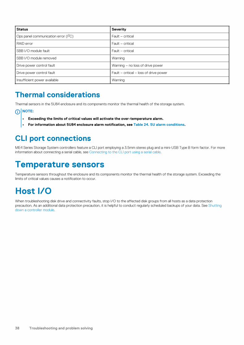
Status Severity
Ops panel communication error (I2C) Fault – critical
RAID error Fault – critical
SBB I/O module fault Fault – critical
SBB I/O module removed Warning
Drive power control fault Warning – no loss of drive power
Drive power control fault Fault – critical – loss of drive power
Insufficient power available Warning
Thermal considerationsThermal sensors in the 5U84 enclosure and its components monitor the thermal health of the storage system.
NOTE:
• Exceeding the limits of critical values will activate the over-temperature alarm.
• For information about 5U84 enclosure alarm notification, see Table 24. 5U alarm conditions.
CLI port connectionsME4 Series Storage System controllers feature a CLI port employing a 3.5mm stereo plug and a mini-USB Type B form factor. For more information about connecting a serial cable, see Connecting to the CLI port using a serial cable.
Temperature sensorsTemperature sensors throughout the enclosure and its components monitor the thermal health of the storage system. Exceeding the limits of critical values causes a notification to occur.
Host I/OWhen troubleshooting disk drive and connectivity faults, stop I/O to the affected disk groups from all hosts as a data protection precaution. As an additional data protection precaution, it is helpful to conduct regularly scheduled backups of your data. See Shutting down a controller module.
38 Troubleshooting and problem solving

Module removal and replacement
ESD precautionsBefore you begin any of the procedures, consider the following precautions and preventive measures.
Preventing electrostatic dischargeTo prevent electrostatic discharge (ESD) from damaging the system, be aware of the precautions to consider when setting up the system or handling parts. A discharge of static electricity from a finger or other conductor may damage system boards or other static-sensitive devices. This type of damage may reduce the life expectancy of the device.
CAUTION: Parts can be damaged by electrostatic discharge. Follow these precautions:
• Avoid hand contact by transporting and storing products in static-safe containers.
• Keep electrostatic-sensitive parts in their containers until they arrive at static-protected workstations.
• Place parts in a static-protected area before removing them from their containers.
• Avoid touching pins, leads, or circuitry.
• Always be properly grounded when touching a static-sensitive component or assembly.
• Remove clutter (plastic, vinyl, foam) from the static-protected workstation.
Grounding methods to prevent electrostatic dischargeSeveral methods are used for grounding. Adhere to the following precautions when handling or installing electrostatic-sensitive parts.
CAUTION: Parts can be damaged by electrostatic discharge. Use proper anti-static protection:
• Keep the replacement CRU in the ESD bag until needed; and when removing a CRU from the enclosure, immediately
place it in the ESD bag and anti-static packaging.
• Wear an ESD wrist strap connected by a ground cord to a grounded workstation or unpainted surface of the
computer chassis. Wrist straps are flexible straps with a minimum of 1 megohm (± 10 percent) resistance in the
ground cords. To provide proper ground, wear the strap snug against the skin.
• If an ESD wrist strap is unavailable, touch an unpainted surface of the chassis before handling the component.
• Use heel straps, toe straps, or boot straps at standing workstations. Wear the straps on both feet when standing on
conductive floors or dissipating floor mats.
• Use conductive field service tools.
• Use a portable field service kit with a folding static-dissipating work mat.
If you do not have any of the suggested equipment for proper grounding, have an authorized technician install the part. For more information about static electricity or assistance with product installation, contact customer support. For additional information, see www.dell.com/support.
Dealing with hardware faultsEnsure that you have obtained a replacement module of the same type before removing any faulty module.
CAUTION:
• If the enclosure system is powered up and you remove any module, replace it immediately. If the enclosure system
operates for too long with a module removed, the enclosures can overheat, causing power failure and potential data
loss. Such use may invalidate the warranty.
3
Module removal and replacement 39

• Observe applicable/conventional ESD precautions when handling modules and components, as described in
Replacing controller modules in a dual-controller module enclosure. Avoid contact with midplane components,
module connectors, leads, pins, and exposed circuitry.
Firmware updatesAfter installing the hardware and powering on the storage system components for the first time, verify that the controller modules, expansion modules, and disk drives are using the current firmware release. Periodically, ensure that the firmware versions used in the enclosure modules are compatible.
Configuring partner firmware updateIn a dual-controller system in which partner firmware update (PFU) is enabled, when you update firmware on one controller, the system automatically updates the partner controller. Disable PFU only if requested by a service technician. Use the PowerVault Manager or CLI to change the PFU setting.
NOTE:
• See the topic about updating firmware in the Dell EMC PowerVault ME4 Series Storage System Administrator’s Guide before performing a firmware update.
• The PowerVault Manager and CLI provide an option for enabling or disabling PFU for the partner controller as
described in the Dell EMC PowerVault ME4 Series Storage System Administrator’s Guide. To enable or disable the
setting via the CLI, use the set advanced-settings command, and set the partner-firmware-upgrade parameter. See
the Dell EMC PowerVault ME4 Series Storage System CLI Guide for more information about command parameter
syntax.
Continuous operation during replacementYour hardware or software enclosure management application determines the capability for replacing a failed disk without the loss of access to any file system on the enclosure. Enclosure access and use during this period is uninterrupted. If an enclosure is equipped with redundant PCMs or PSU, sufficient power is provided to the system while the faulty module is replaced.
NOTE: ME4 Series Storage System enclosures support hot-plug replacement of redundant controller modules, power
supplies, and expansion modules. Hot-add replacement of expansion enclosures is also supported.
Shutting down attached hostsTo replace modules in a 2U controller enclosure that has one controller module, you must shut down all of the attached hosts before shutting down the controller module.
To replace the sideplane in a 5U84 enclosure, you must shut down all of the attached hosts before shutting down the controller modules.
CAUTION: The sideplanes on the enclosure drawers are not hot swappable or customer serviceable.
Shutting down a controller moduleShutting down the controller module in an enclosure ensures that a proper failover sequence is used, which includes stopping all I/O operations and writing any data in write cache to disk. Perform a shut down before you remove a controller module from an enclosure, or before you power off an enclosure for maintenance, repair, or a move.
Using the PowerVault Manager1. Sign-in to the PowerVault Manager.
2. In the System panel in the banner, click Restart System.The Controller Restart and Shut Down panel opens.
3. Select the Shut Down operation, which automatically selects the controller type Storage.
4. Select the controller module to shut down: A, B, or both.
40 Module removal and replacement

5. Click OK. A confirmation panel appears.
6. ClickYes to continue; otherwise, click No. If you clicked Yes, a message describes shutdown activity.
NOTE:
• If an iSCSI port is connected to a Microsoft Windows host, the following event is recorded in the Windows event log:
Initiator failed to connect to the target.
• See the Dell EMC PowerVault ME4 Series Storage System Administrator’s Guide for additional information.
Using the CLI1. Log-in to the CLI.
2. In your dual-controller system, verify that the partner controller is online by running the command: show controllers
3. Shut down the failed controller—A or B—by running the command: shutdown a or shutdown bThe blue OK to Remove LED (back of enclosure) illuminates to indicate that the controller module can be safely removed.
4. Illuminate the white Identify LED of the enclosure that contains the controller module to remove by running the command: set led enclosure 0 onThe Display LED on the Ops panel located on the enclosure left ear will be blinking green when theset led enclosure 0 on command is invoked.
NOTE: See the Dell EMC PowerVault ME4 Series Storage System CLI Guide for additional information.
Verifying component failureSelect from the following methods to verify component failure:
• Use the PowerVault Managerto check the health icons/values of the system and its components to either ensure that everything is okay, or to drill down to a problem component. The PowerVault Manager uses health icons to show OK, Degraded, Fault, or Unknown status for the system and its components. If you discover a problem component, follow the actions in its Recommendation field to resolve the problem.
• As an alternative to using the PowerVault Manager, you can run the CLI show system command to view the health of the system and its components. If any component has a problem, the system health will be Degraded, Fault, or Unknown. If you discover a problem component, follow the actions in its Health Recommendations field to resolve the problem.
• Monitor event notification — With event notification configured and enabled, use the PowerVault Manager to view the event log, or run the CLI show events detail command to see details for events.
• Check Fault LED (back of enclosure on controller module or IOM face plate): Amber = Fault condition.• Check that the OK LED (back of enclosure) is off.
Customer-replaceable units (CRUs)NOTE: See 2U enclosure core product and 5U84 enclosure core product for views of controller module and IOM CRUs
used in the different enclosure form factors supported by ME4 Series storage systems.
Table 25. ME4 Series enclosure models
ME4 Series: 4–port controller enclosure matrix - 2U
2.5" (SFF) 24-drive controller enclosures
Model Description Form Description Form
ME4024 Fibre Channel (16Gb/s) SFP1,3 2U24 Fibre Channel (16Gb/s) SFP1,3 2U12
ME4024 Internet SCSI (10GbE) SFP2,3 2U24 Internet SCSI (10GbE) SFP2,3 2U12
ME4024 HD mini-SAS (12Gb/s)4 2U24 HD mini-SAS (12Gb/s)4 2U12
ME4024 iSCSI 10Gbase-T (10Gb/s or 1Gb/s)5 2U24 iSCSI 10Gbase-T (10Gb/s or 1Gb/s)5 2U12
1-This model uses a qualified FC SFP option within the CNC ports (used for host connection). When in FC mode, the SFPs must be a qualified 16Gb fiber-optic option. A 16Gb/s SFP can run at 16Gb/s, 8Gb/s, 4Gb/s, or auto-negotiate its link speed.
Module removal and replacement 41

2-This model uses a qualified 10GbE iSCSI option within the controller module CNC ports (used for host connection).
3-CNC ports support same-type or mixed-type SFPs in combination.
4-This model uses SFF-8644 connectors and qualified cable options for host connection.
5-This model supports 10Gb/s or 1Gb/s speeds (used for iSCSI host connection).
Table 26. High-density ME4 Series enclosure models
High-density 4-port controller enclosure matrix–5U
ME4 Series (2.5"/3.5") 84-drive controller enclosures
Model Description Form
ME4084 Fibre Channel (16Gb/s) SFP1,3 5U84
ME4084 Internet SCSI (10GbE) SFP2,4 5U84
ME4084 HD mini-SAS (12Gb/s)4 5U84
ME4084 iSCSI 10Gbase-T (10Gb/s or 1Gb/s)5 5U84
1-This model uses a qualified FC SFP option within the CNC ports (used for host connection). When in FC mode, the SFPs must be a qualified 16Gb fiber-optic option. A 16Gb/s SFP can run at 16Gb/s, 8Gb/s, 4Gb/s, or auto-negotiate its link speed.
2-This model uses a qualified 10GbE iSCSI option within the controller module CNC ports (used for host connection).
3-CNC ports support same-type or mixed-type SFPs in combination.
4-This model uses SFF-8644 connectors and qualified cable options for host connection.
5-This model supports 10Gb/s or 1Gb/s speeds (used for iSCSI host connection).
Attach or remove the front bezel of a 2U enclosureThe following figure shows a partial view of a 2U12 enclosure:
Figure 37. Attaching or removing the 2U enclosure front bezel
To attach the front bezel to the 2U enclosure:
1. Locate the bezel, and while grasping it with your hands, face the front panel of the 2U12 or 2U24 enclosure.2. Hook the right end of the bezel onto the right ear cover of the storage system.3. Insert the left end of the bezel into the securing slot until the release latch snaps in place.4. Secure the bezel with the keylock as shown in Attaching or removing the 2U enclosure front bezel.
To remove the bezel from the 2U enclosure, reverse the order of the preceding steps.
NOTE: See Enclosure variants for details about various enclosure options.
Replacing a drive carrier module in a 2U enclosureThe section describes how to replace a drive carrier module in a 2U enclosure.
A drive carrier module consists of a disk drive that is installed in a carrier module. Drive carrier modules are hot-swappable, which means they can be replaced without halting I/O to the disk groups, or powering off the enclosure. The new disk drive must be of the same type
42 Module removal and replacement

of drive and contain a capacity equal to or greater than the drive being replaced. Otherwise, the storage system cannot use the new disk drive to reconstruct the disk group.
CAUTION:
• Removing a drive carrier module impacts the airflow and cooling ability of the enclosure. If the internal temperature
exceeds acceptable limits, the enclosure may overheat and automatically shut down or restart.
• When removing a drive carrier module, wait 30 seconds after unseating the drive carrier module to allow the disk
drive to stop spinning.
NOTE:
• Familiarize yourself with full disk encryption (FDE) considerations relative to disk drive installation and replacement.
• When moving FDE-capable disk drives for a disk group, stop I/O to the disk group before removing the drive carrier
modules. Import the keys for the disk drives so that the drive content becomes available. See the Dell EMC PowerVault ME4 Series Storage System Administrator’s Guide or Dell EMC PowerVault ME4 Series Storage System CLI Guide for more information.
Before you begin any of the procedures, see the ESD precautions.
Replacing an LFF drive carrier moduleThe replacement procedures for LFF drive carrier modules are the same for SFF modules, except that the LFF drive carrier modules are mounted horizontally.
Removing an LFF drive carrier modulePerform the following steps to remove an LFF drive carrier module from a 2U enclosure:
1. Press the latch on the drive module carrier to open the handle.
Figure 38. Removing an LFF drive carrier module (1 of 2)
2. Gently move the drive carrier module approximately 25 mm (1 in.), and then wait 30 seconds for the drive to spin down.
Module removal and replacement 43
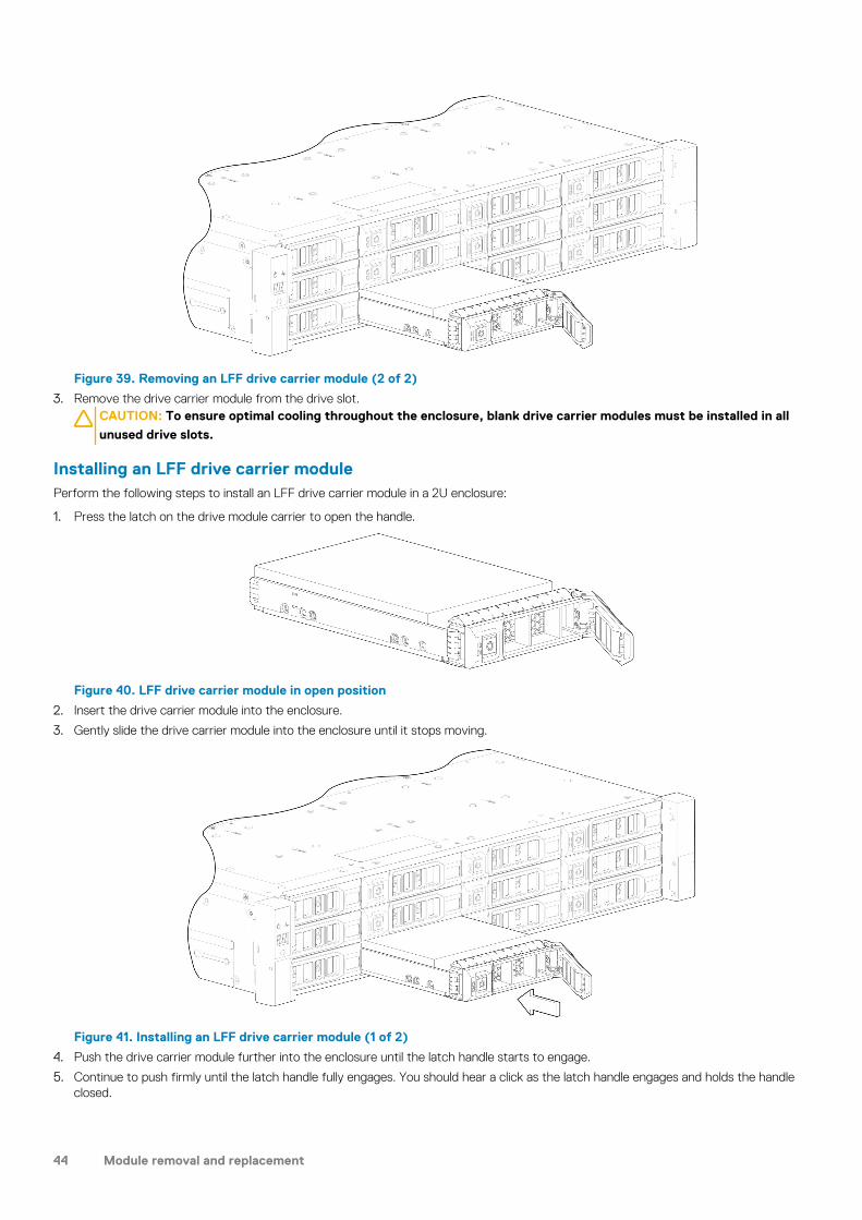
Figure 39. Removing an LFF drive carrier module (2 of 2)
3. Remove the drive carrier module from the drive slot.CAUTION: To ensure optimal cooling throughout the enclosure, blank drive carrier modules must be installed in all
unused drive slots.
Installing an LFF drive carrier modulePerform the following steps to install an LFF drive carrier module in a 2U enclosure:
1. Press the latch on the drive module carrier to open the handle.
Figure 40. LFF drive carrier module in open position
2. Insert the drive carrier module into the enclosure.
3. Gently slide the drive carrier module into the enclosure until it stops moving.
Figure 41. Installing an LFF drive carrier module (1 of 2)
4. Push the drive carrier module further into the enclosure until the latch handle starts to engage.
5. Continue to push firmly until the latch handle fully engages. You should hear a click as the latch handle engages and holds the handle closed.
44 Module removal and replacement

Figure 42. Installing an LFF drive carrier module (2 of 2)
6. Use the PowerVault Manager or CLI to verify the following:
• Health of the new disk drive is OK• Green Disk Activity LED is on/blinking• Ops panel states show no amber module faults
Replacing an SFF drive carrier moduleThe replacement procedures for SFF drive carrier modules are the same for LFF modules, except that the SFF drive carrier modules are mounted vertically.
Removing an SFF drive carrier modulePerform the following steps to remove an SFF drive carrier module from a 2U enclosure:
1. Press the latch on the drive module carrier to open the handle.
Figure 43. Removing an SFF drive module carrier (1 of 2)
2. Gently move the drive carrier module approximately 25 mm (1 in.), and then wait 30 seconds for the drive to spin down.
Module removal and replacement 45

Figure 44. Removing an SFF drive module carrier (2 of 2)
3. Remove the drive carrier module from the drive slot.CAUTION: To ensure optimal cooling throughout the enclosure, blank drive carrier modules must be installed in all
unused drive slots.
Installing an SFF drive carrier modulePerform the following steps to install an SFF drive carrier module in a 2U enclosure:
1. Press the latch on the drive module carrier to open the handle.
Figure 45. SFF drive carrier module in open position
2. Insert the drive carrier module into the enclosure.
3. Gently slide the drive carrier module into the enclosure until it stops moving.
Figure 46. Installing an SFF drive carrier module (1 of 2)
46 Module removal and replacement

4. Push the drive carrier module further into the enclosure until the latch handle starts to engage.
5. Continue to push firmly until the latch handle fully engages. You should hear a click as the latch handle engages and holds the handle closed.
Figure 47. Installing an SFF drive carrier module (2 of 2)
6. Use the PowerVault Manager or CLI to verify the following:
• Health of the new disk drive is OK• Green Disk Activity LED is on/blinking• Ops panel states show no amber module faults
Replacing a blank drive carrier moduleEnsure optimal cooling throughout the enclosure by installing blank drive carrier modules into all unused drive slots.
To remove a blank drive carrier module, press the latch on the module and pull the module out of the drive slot.
To install a blank drive carrier module, insert the module into the drive slot and push the module into the drive slot to secure it in place.
Replacing a DDIC in a 5U enclosureThe section describes how to replace a Disk Drive in Carrier (DDIC) in a 5U enclosure.
A DDIC consists of a disk drive that is installed in a carrier module. DDICs are hot-swappable, which means they can be replaced without halting I/O to the disk groups, or powering off the enclosure. The new disk drive must be of the same type of drive and contain a capacity equal to or greater than the drive being replaced. Otherwise, the storage system cannot use the new disk drive to reconstruct the disk group.
CAUTION:
• Removing a DDIC impacts the airflow and cooling ability of the enclosure. If the internal temperature exceeds
acceptable limits, the enclosure may overheat and automatically shut down or restart.
• When removing a DDIC, wait 30 seconds after unlocking the DDIC from its seated position to allow the disk drive to
stop spinning.
NOTE:
• Familiarize yourself with full disk encryption (FDE) considerations relative to disk drive installation and replacement.
• When moving FDE-capable disk drives for a disk group, stop I/O to the disk group before removing the DDICs.
Import the keys for the disk drives so that the drive content becomes available. See the Dell EMC PowerVault ME4 Series Storage System Administrator’s Guide or Dell EMC PowerVault ME4 Series Storage System CLI Guide for
more information.
Before you begin any of the procedures, see the ESD precautions.
Module removal and replacement 47

Accessing the drawers of a 5U84 chassisThe replacement procedure for DDICs must be completed within two minutes of opening a drawer.
Opening a drawer
1. Verify that the anti-tamper locks are not engaged. The red arrows on the locks point inwards if the locks are disengaged as shown in the following figure. If necessary, unlock them by rotating counter-clockwise using a Torx T20 bit.
Figure 48. Drawer front panel details
1. Left side 2. Right side
3. Anti-tamper lock 4. Sideplane OK/Power Good
5. Drawer Fault 6. Logical Fault
7. Cable Fault 8. Drawer Activity
9. Drawer pull handle
2. Push the drawer latches inward and hold them as shown in the following figure.
Figure 49. Opening a drawer (1 of 2)
3. Pull the drawer outward until it locks at the drawer stops as shown in the following figure.The drawer is shown empty, which is how the enclosure is delivered. A drawer slide rail latch detail is inset.
48 Module removal and replacement

Figure 50. Opening a drawer (2 of 2)
NOTE: The drawer must not remain open for more than two minutes while the enclosure is powered on.
Closing a drawer
1. Press and hold the black latches on the sides of the open drawer in each extended top rail.The previous diagram shows a magnified detail of a slide latch, which resides on the left and right drawer rails.
2. Push the drawer in slightly.
3. Release the drawer latches.
4. Push the drawer all the way into the enclosure, making sure that it clicks home.
Removing a DDIC from a 5U enclosureRemove a DDIC only if a replacement DDIC is available.
NOTE: Closing a drawer with one or more DDICs missing can potentially cause cooling problems. See Populating
drawers.
1. Determine which drawer contains the disk drive to remove.
• If the slot number is known, see Figure 20. 5U84 enclosure system - plan view of drawer accessed from front panel, which provides a view of a drawer that is dual-indexed with top drawer (left integer) and bottom drawer (right integer) slot numbering.
• If the disk drive has failed, a fault LED is lit on the front panel of the affected drawer.• If the disk drive has failed, the Drive Fault LED on the DDIC is lit amber.
2. Open the drawer that contains the DDIC to remove.
3. Unlock the DDIC from its seated position in the slot by pushing the latch button in the direction shown in the following figure:
Figure 51. Removing a DDIC (1 of 2)
4. Pull the DDIC upwards and out of the drawer slot.
Module removal and replacement 49
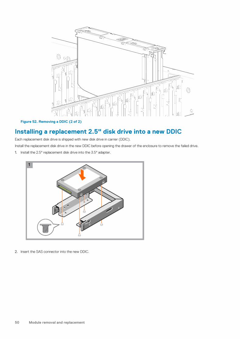
Figure 52. Removing a DDIC (2 of 2)
Installing a replacement 2.5" disk drive into a new DDICEach replacement disk drive is shipped with new disk drive in carrier (DDIC).
Install the replacement disk drive in the new DDIC before opening the drawer of the enclosure to remove the failed drive.
1. Install the 2.5" replacement disk drive into the 3.5" adapter.
2. Insert the SAS connector into the new DDIC.
50 Module removal and replacement

3. Insert the 3.5" adapter with the 2.5" disk drive into the new DDIC and connect the disk drive to the SAS connector.
4. Attach the bottom bracket to the new DDIC.
Module removal and replacement 51

5. Secure the disk drive in the new DDIC using the four screws shipped with the new DDIC.
6. Attach the appropriate disk drive size label to the top of the new DDIC.
Installing a replacement 3.5" disk drive into a new DDICEach replacement disk drive is shipped with new disk drive in carrier (DDIC).
Install the replacement disk drive in the new DDIC before opening the drawer of the enclosure to remove the failed drive.
1. Remove the protective plastic from the new DDIC.
52 Module removal and replacement

2. Insert the SAS connector into the new DDIC.
3. Insert the disk drive into the new DDIC and connect the disk drive to the SAS connector. .
Module removal and replacement 53

4. Attach the bottom bracket to the new DDIC.
5. Secure the disk drive in the new DDIC using the four screws shipped with the new DDIC.
54 Module removal and replacement

6. Attach the appropriate disk drive size label to the top of the new DDIC.
Installing a DDIC in a 5U enclosureFailed disk drives must be replaced with approved disk drives. Contact your service provider for details.
1. Align the DDIC with the target drive slot as shown in Figure 52. Removing a DDIC (2 of 2) and insert it into the drive slot.
2. Lower the DDIC into the drive slot.
a) Push the DDIC downwards and hold it down.b) Move the slide latch in the direction shown in the following figure:
Figure 53. Installing a DDIC
a. Slide latch (slides left)b. Latch button (shown in locked position)
Module removal and replacement 55

c. Drive Fault LED
3. Verify the following:
a) The latch button is in the locked position.b) The Drive Fault LED is not lit.
4. Close the drawer.
Populating drawersThe general guidelines for populating a drawer with DDICs are provided in the Dell EMC PowerVault ME4 Series Storage System Deployment Guide. Additional guidelines are provided for replacing disk drives in previously populated drawers, or populating enclosures delivered with the half-populated enclosure configuration option.
PreparationDisk drives are shipped in expansion packages of 42 drives. Customers with multiple enclosures may spread the 42 disk drives of an expansion package across multiple enclosures, provided that the DDICs are installed 14 at a time to completely fill empty rows. The installation pattern providing the best airflow and thermal performance is described in this section.
The drawers must be populated with DDICs in whole rows. Each drawer contains 3 rows of 14 DDICs. Rules and assumptions are listed:
• The minimum number of DDICs in an enclosure is 28.• The number of rows must not differ by more than 1 between the top and bottom drawers.• The rows should be populated from the front of the drawer to the rear of the drawer• If a second expansion package of disk drives is shipped to a customer, the disk drives of the second expansion package must match
the disk drives that were originally shipped with the 5U84 enclosure. Both groups of disk drives must share the same model type and capacity.
NOTE: Part numbers for expansion packages are not listed because they change over time when disk drives ship with
new firmware, or new disk drive models become available. Contact your account manager for part numbers.
• If the two groups of disk drives have different firmware, all disk drives must be updated with current/compatible firmware. See the Dell EMC PowerVault ME4 Series Storage System Administrator’s Guide or online help for additional information about updating firmware.
Installation guidelines
The recommended order for partially populating disk drives in the 5U84 enclosure optimizes the airflow through the chassis. Figure 19. 5U84 enclosure—front panel components shows the location and indexing of drawers accessed from the enclosure front panel.
The 5U84 ships with drawers installed in the chassis. However, to avoid shock and vibration issues during transit, the enclosure does not ship with DDICs installed in the drawers. An enclosure is configured with either 42 disk drives (half-populated) or 84 disk drives (fully populated) for customer delivery. If half-populated, the rows containing disk drives should be populated with a full complement of DDICs (no blank slots in the row). The following list identifies rows in drawers that should contain DDICs when the enclosure is configured as half-populated:
• Top drawer–front row• Top drawer–middle row• Bottom drawer–front row
If additional disk drives are incrementally installed into a half-populated enclosure, the DDICs must be added one complete row at a time (no blank slots in row) in the sequence listed:
• Bottom drawer–middle row• Top drawer–back row• Bottom drawer–back row
Replacing a controller module or IOM in a 2U or 5U enclosureThis section provides procedures for removing and installing a controller module or IOM in a 2U or 5U enclosure.
The 2U enclosures support single or dual-controller module configurations. The 5U84 enclosures support only dual-controller module configurations.
If a controller module fails, the controller will fail over and run on a single controller module until the redundancy is restored. For 2U enclosures, an controller module must be installed in slot A, and either a controller module or controller blank must be installed in slot B to ensure sufficient air flow through the enclosure during operation. For 5U84 enclosures, an controller module must be installed in both slots.
56 Module removal and replacement

In a dual-controller module configuration, controller modules and IOMs are hot-swappable, which means you can replace one module without halting I/O to disk groups, or powering off the enclosure. In this case, the second controller module takes over operation of the storage system until you install the new module.
You might need to replace a controller module or IOM when:
• The Fault LED is illuminated• Health status reporting in the PowerVault Managerindicates a problem with the module• Events in thePowerVault Manager indicate a problem with the module• Troubleshooting indicates a problem with the module
The figure in the following sections show controller module replacement for the top slot (A) of the enclosure. To replace a controller module or IOM in the bottom slot (B), rotate the module 180º so that it properly aligns with its connectors on the back of the midplane.
Replacing controller modules in a dual-controller module enclosureRemoving a controller module from an operational enclosure significantly changes air flow within the enclosure. Slot openings must be populated by controller modules for the enclosure to cool properly. Leave the controller modules in the enclosure until you are ready to install a replacement controller module.
When two controller modules are installed in an enclosure, the controller modules must be the same model type.
CAUTION: When replacing a controller module, ensure that less than 10 seconds elapse between inserting it into a slot
and fully latching it in place. Not doing so might cause the controller to fail. If it is not latched within 10 seconds,
remove the controller module from the slot, and repeat the process.
Follow these guidelines when replacing one controller module in an operational enclosure:
1. Record the controller module settings before replacing the controller modules.2. Remove the controller module from the enclosure.3. Install the replacement controller module in the enclosure.4. Wait 30 minutes, then use the PowerVault Manager or CLI to check the system status and event logs to verify that the system is
stable.NOTE: If the Partner Firmware Update (PFU) feature is not enable, update the firmware on the replacement
controller module.
Follow these guidelines when replacing both controller modules in an operational enclosure:
1. Record the controller module settings before replacing the controller modules.2. Remove one controller module from the enclosure.3. Install the replacement controller module in the enclosure.4. Wait 30 minutes, then use the PowerVault Manager or CLI to check the system status and event logs to verify that the system is
stable.NOTE: If the Partner Firmware Update (PFU) feature is not enable, update the firmware on the replacement
controller module. For more information updating the firmware, see the Dell EMC PowerVault ME4 Series Storage System Administrator's Guide.
5. Remove the second controller module from the enclosure.6. Install the replacement controller module in the enclosure.7. Wait 30 minutes, then use the PowerVault Manager or CLI to check the system status and event logs to verify that the system is
stable.NOTE: If the Partner Firmware Update (PFU) feature is not enable, update the firmware on the replacement
controller module. For more information updating the firmware, see the Dell EMC PowerVault ME4 Series Storage System Administrator's Guide.
Removing a controller module from a dual-controller module enclosurePerform the following steps to remove a controller module from a dual-controller module enclosure:
Before you begin any procedure, see ESD precautions.NOTE:
• You may hot-swap a single controller module in an operational enclosure, provided you first shut down the controller
module using the PowerVault Manager or the CLI.
• Do not remove a faulty controller module unless its replacement is on-hand. All controller modules must be in place
when the system is in operation.
Module removal and replacement 57

1. Verify that you have successfully shut down the controller module using the PowerVault Manager or the CLI.
2. Locate the enclosure with a UID LED that is illuminated.
3. Within the enclosure, locate the controller module with an OK to Remove LED that is blue.
4. Disconnect any cables connected to the controller module.Label each cable to facilitate re-connection to the replacement controller module.
5. Grasp the module latch between the thumb and forefinger, and squeeze the flange and handle together to release the latch handle, and swing the latch handle out to release the controller module from its seated position.
Figure 54. Removing a controller module from an enclosure
NOTE: Removing a controller module shows a 4-port SAS controller module. However, all of the controller modules
use the same latching mechanism.
6. Swing the latch handle open, then grip the latch handle and ease the controller module forward from the slot.
7. Place both hands on the controller module body, and pull it straight out of the enclosure such that the controller module remains level during removal.
Installing a controller module in a dual-controller module enclosurePerform the following steps to install a controller module in a dual-controller module enclosure:
Before you begin any procedure, see ESD precautions.
1. Examine the controller module for damage, and closely inspect the interface connector. Do not install the controller module if the pins are bent.
2. Grasp the controller module using both hands, and with the latch in the open position, orient the controller module and align it for insertion into the target slot.
3. Ensuring that the controller module is level, slide it into the enclosure until it stops.A controller module that is only partially seated will prevent optimal performance of the controller enclosure. Verify that the controller module is fully seated before continuing.
4. Secure the controller module in position by manually closing the latch.You should hear a click as the latch handle engages and secures the controller module to its connector on the back of the midplane.
58 Module removal and replacement

5. Reconnect the cables.
CAUTION: If passive copper cables are connected to the controller module, the cable must not have a connection to
a common ground/earth point.
6. Update the firmware on the controller module.NOTE: In a dual-controller module system in which PFU is enabled, the system automatically updates the firmware
on a replacement controller module.
Removing an IOMBefore you begin any procedure, see ESD precautions.
NOTE: Considerations for removing IOM:
• Expansion enclosures are equipped with two IOMs. You may hot-swap a single IOM in an operational enclosure.
• If replacing both IOMs,—and the expansion enclosure is online—you can hot-swap the IOM in slot “A”, and then
hot-swap the IOM slot “B”, verifying each module is recognized by the controller.
• Do not remove a faulty IOM unless its replacement is on-hand. All IOMs must be in place when the system is in
operation.
1. Locate the expansion enclosure containing the IOM that must be replaced. On the enclosure front panel, check for an amber fault condition on the enclosure Ops panel. On the enclosure rear panel, look for amber illumination of the IOM Fault LED.
2. Disconnect any cables connected to the IOM.Label each cable to facilitate re-connection to the replacement IOM.
3. Grasp the module latch between the thumb and forefinger, and squeeze the flange and handle together to release the latch handle, and swing the latch handle out to release the IOM from its seated position.
Figure 55. Removing an IOM from an enclosure
4. NOTE: Figure 55. Removing an IOM from an enclosure shows a 4-port SAS controller module instead of an IOM.
However, an IOM uses the same latching mechanism as the controller module.
5. Swing the latch handle open, then grip the latch handle and ease the IOM forward from the slot.
Module removal and replacement 59

6. Place both hands on the IOM body, and pull it straight out of the enclosure such that the IOM remains level during removal.
Installing an IOMBefore you begin any procedure, see ESD precautions.
1. Examine the IOM for damage, and closely inspect the interface connector. Do not install the IOM if the pins are bent.
2. Grasp the IOM using both hands, and with the latch in the open position, orient the IOM and align it for insertion into the target slot.
3. Ensuring that the IOM is level, slide it into the enclosure as far as it will go.An IOM that is only partially seated will prevent optimal performance of the expansion enclosure. Verify that the IOM is fully seated before continuing.
4. Secure the IOM in position by manually closing the latch.
You should hear a click as the latch handle engages and secures the IOM to its connector on the back of the midplane.
5. Reconnect the cables.
Replacing a power supply unit (PSU) in a 5U enclosureThis section provides procedures for removing and installing a PSU in a 5U enclosure.
The images in the PSU removal and installation procedures show rear panel views of the 5U enclosure.
Before you begin any procedure, see ESD precautions.
Removing a PSUBefore removing the PSU, disconnect the power from the PSU by either the mains switch (where present) or by physically removing the power source in order to ensure your system has warning of imminent power shutdown. Make sure that you correctly identify the faulty PSU before beginning the step procedure.
CAUTION: Removing a power supply unit significantly disrupts the enclosure’s airflow. Do not remove the PSU until you
have received the replacement module. It is important that all slots are filled when the enclosure is in operation.
1. Stop all I/O from hosts to the enclosure. See Shutting down a controller module.
NOTE: This step is not required for hot-swapping. However, it is required when replacing both PSUs at once.
2. Use management software to shut down any other system components necessary.
NOTE: This step is not required for hot-swapping. However, it is required when replacing both PSUs at once.
3. Verify the Power OK LED is lit, then switch off the faulty PSU, and disconnect the power supply cable.
4. If replacing a single PSU via hot-swap, proceed to step 6.
5. If replacing both PSUs, verify that the enclosure was shut down using management interfaces, and that the enclosure is powered off.
6. Verify that the power cable is disconnected.
7. Push the release latch to the right and hold it in place (detail No.1).
8. With your other hand, grasp the handle and pull the PSU outward (detail No.2).
Figure 56. Removing a PSU (1 of 2)
60 Module removal and replacement

Figure 57. Removing a PSU (2 of 2)
9. While supporting the PSU with both hands, remove it from the enclosure.
10. If replacing both PSUs, repeat steps 5 through 9.
NOTE: The PSU slot must not be empty for more than 2 minutes while the enclosure is powered.
Installing a PSUIf replacing both PSUs, the enclosure must be powered off via an orderly shutdown using the management interfaces.
1. Make sure that the PSU is switched off.
2. Orient the PSU for insertion into the target slot on the enclosure rear panel, as shown in Figure 57. Removing a PSU (2 of 2).
3. Slide the PSU into the slot until the latch clicks home.
4. Connect the AC power cord.
5. Move the PSU power switch to the On position.
6. Wait for the Power OK LED on the newly inserted PSU to illuminate green. See Figure 25. Power supply unit (PSU).
• If the Power OK LED does not illuminate, verify that the PSU is properly inserted and seated in the slot.• If properly seated, the module may be defective. Check the PowerVault Manager and the event logs for more information.• Using the management interfaces (the PowerVault Manager or CLI), determine if the health of the new PSU is OK. Verify that the
Power OK LED is green, and that the Ops panel states show no amber module faults.
7. If replacing both PSUs, repeat steps 1 through 6.
Replacing a fan cooling module (FCM) in a 5U enclosureThis section provides procedures for removing and installing an FCM in a 5U enclosure.
The images in the FCM removal and installation procedures show rear panel views of the 5U enclosure.
Before you begin any procedure, see ESD precautions.
Removing an FCMYou can change all fan cooling modules as long as they are removed and inserted one at a time. We recommend that you shut down the unit before removing two or more fans.
CAUTION: Removing an FCM significantly disrupts the enclosure’s airflow. Do not remove the FCM until you have
received the replacement module. It is important that all slots are filled when the enclosure is in operation.
1. Identify the fan cooling (FCM) module to be removed. If the FCM module has failed, the Fan Fault LED will illuminate amber. See Figure 26. Fan cooling module (FCM).
2. Push the release latch down and hold it in place (detail No.1).
3. With your other hand, grasp the handle and pull the FCM outward (detail No.2).
Module removal and replacement 61

Figure 58. Removing an FCM (1 of 2)
4. While supporting the FCM with both hands, remove it from the enclosure.
Figure 59. Removing an FCM (2 of 2)
NOTE: The FCM slot must not be empty for more than 2 minutes while the enclosure is powered.
Installing an FCMYou can hotswap the replacement of a single FCM; however, if replacing multiple FCMs, the enclosure must be powered off using an orderly shutdown using the management interfaces.
1. Orient the FCM for insertion into the target slot on the enclosure rear panel, as shown in Figure 59. Removing an FCM (2 of 2).
2. Slide the FCM into the slot until the latch clicks home.The enclosure should automatically detect and make use of the new module.
3. Wait for the Module OK LED on the newly inserted FCM to illuminate green. See Figure 26. Fan cooling module (FCM).
• If the Module OK LED does not illuminate, verify that the FCM is properly inserted and seated in the slot.• If properly seated, the module may be defective. Check the PowerVault Manager and the event logs for more information.• Using the management interfaces (the PowerVault Manager or CLI), determine if the health of the new FCM is OK. Verify that the
Module OK LED is green, and that the Ops panel states show no amber module faults.
4. If replacing multiple FCMs, repeat steps 1 through 4.
Replacing a power cooling module (PCM) in a 2U enclosureThis section provides procedures for removing and installing a PCM in a 2U enclosure.
The images in the PCM removal and installation procedures show rear panel views of the 2U enclosure.
A single PCM is sufficient to maintain operation of the enclosure. You need not halt operations and completely power-off the enclosure when replacing only one PCM; however, a complete orderly shutdown is required if replacing both units simultaneously.
62 Module removal and replacement

CAUTION: Do not remove the cover from the PCM due to danger from electric shock inside. Return the PCM to your
supplier for repair.
Before you begin any of the procedures, see the ESD precautions.
NOTE: The figures show PCM module replacement within the right slot as you view the enclosure rear panel. To replace
a PCM in the left slot, rotate the module 180º so that it properly aligns with its connectors on the back of the midplane.
Removing a PCMCAUTION: Removing a power supply unit significantly disrupts the enclosure’s airflow. Do not remove the PCM until you
have received the replacement module. It is important that all slots are filled when the enclosure is in operation.
Before removing the PCM, disconnect the power from the PCM by either the mains switch (where present) or by physically removing the power source in order to ensure your system has warning of imminent power shutdown. Ensure that you correctly identify the faulty PCM before beginning the step procedure.
1. Stop all I/O from hosts to the enclosure. See Shutting down attached hosts.
NOTE: This step is not required for hot-swapping. However, it is required when replacing both PCMs at once.
2. Use management software to shut down any other system components necessary.
NOTE: This step is not required for hot-swapping. However, it is required when replacing both PCMs at once.
3. Switch off the faulty PCM, and disconnect the power supply cable.
4. If replacing a single PCM using hot-swap, proceed to step 6.
5. If replacing both PCMs, verify that the enclosure was shut down using management interfaces, and that the enclosure is powered off.
6. Verify that the power cable is disconnected.
7. Grasp the latch and the side of the PCM handle between thumb and forefinger, squeeze together and open the handle to cam the PCM out of the enclosure as shown in the following figure.
Figure 60. Removing a PCM (1 of 2)
8. Grip the handle and withdraw the PCM, taking care to support the base of the module with both hands as you remove it from the enclosure as shown in the following figure.
Module removal and replacement 63

Figure 61. Removing a PCM (2 of 2)
NOTE: The remove PCM illustrations show a chassis configured as a 4-port FC/iSCSI controller enclosure. The
procedure applies to all 2U controller enclosures and expansion enclosures.
9. If replacing two PCMs, repeat steps 5 through 8.
Installing a PCMRefer to Figure 60. Removing a PCM (1 of 2) and Figure 61. Removing a PCM (2 of 2) when performing this procedure, but ignore the directional arrows—since you will insert the module into the slot rather than extract.
NOTE: Handle the PCM carefully, and avoid damaging the connector pins. Do not install the PCM if any pins appear to
be bent.
1. Check for damage, especially to all module connectors.
2. With the PCM handle in the open position, slide the module into the enclosure, taking care to support the base and weight of the module with both hands.
3. Cam the module home by manually closing the PCM handle. You should hear a click as the latch handle engages and secures the PCM to its connector on the back of the midplane.
4. Connect the power cable to the power source and the PCM.
5. Secure the strain relief bales.
6. Using the management interfaces (the PowerVault Manager or CLI), verify whether the health of the new PCM is OK. Verify that the green PCM OK LED is on/blinking per Table 11. PCM LED states. Verify that cooling fans are spinning with no fail states. Verify that Ops panel states show no amber module faults.
7. If replacing two PCMs, repeat steps 1 through 5.
Completing the component installation processThis section provides a procedure for ensuring that the components installed in the replacement controller enclosure chassis function properly.
1. Reconnect data cables between devices, as needed, to return to the original cabling configuration:
• Between cascaded storage enclosures.• Between the controller and peripheral or SAN devices.• Between the controller enclosure and the host.
2. Reconnect power cables to the storage enclosures.
Verifying component operation1. Restart system devices by moving the power switch on the power supply to the On position in the following sequence:
a) Expansion enclosures first.b) Controller enclosure next.
64 Module removal and replacement

c) Data host last (if powered down for maintenance purposes).
Allow time for each device to complete its Power On Self Tests (POST) before proceeding.
2. Perform a rescan to force a fresh discovery of all expansion enclosures connected to the controller enclosure. This step clears the internal SAS layout information, reassigns enclosure IDs, and ensures the enclosures are displayed in the proper order. Use the CLI or PowerVault Manager to perform the rescan:
To perform a rescan using the CLI, enter the following command: rescanTo perform a rescan using the PowerVault Manager:
a) Verify that both controllers are operating normally.b) In the System topic, select Action > Rescan Disk Channels.c) Select Rescan.
Using LEDsThis section describes the LEDs used to verify component operation. These LEDs are located on the enclosure front and rear panels.
Verify front panel LEDsFront panel LEDs reside on the Ops panel located on the left ear flange. Disk LEDs are located on the carrier modules.
• Verify that the System Power On/Standby LED is illuminated green, and that the Module Fault LED is not illuminated.• Verify that the enclosure ID LED located on the left ear is illuminated green.• Verify that the disk module's LED is green or blinking green, and is not amber.
Verify rear panel LEDsRear panel LEDs are located on controller module, IOM, and PCM face plates.
• For controller modules and IOMs, verify that the OK LED is illuminated green, indicating that the module has completed initializing, and is online.
• For PCMs, verify that the PCM OK LED is illuminated green on each PCM.
Using management interfacesIn addition to viewing LEDs as previously described, you can use management interfaces to monitor the health status of the system and its components, provided you have configured and provisioned the system, and enabled event notification.
Select from the following methods to verify component operation:
• Use the PowerVault Manager to check the health icons/values of the system and its components, or to drill down to a problem component. The PowerVault Manager uses health icons to show OK, Degraded, Fault, or Unknown status for the system and its components. If you discover a problem component, follow the actions in its Recommendation field to resolve the problem.
• As an alternative to using the PowerVault Manager, you can run the show system command in the CLI to view the health of the system and its components. If any component has a problem, the system health will be Degraded, Fault, or Unknown. If you discover a problem component, follow the actions in its Health Recommendations field to resolve the problem.
• Monitor event notification — With event notification configured and enabled, you can view event logs to monitor the health of the system and its components. If a message recommends that you check whether an event has been logged, or to view information about an event in the log, you can do so using the PowerVault Manager or the CLI. Using the PowerVault Manager, view the event log and then hover over the event message to see detail about that event. Using the CLI, run the show events detail command with additional parameters to filter the output to see the detail for an event. See the CLI Reference Guide for more information about command parameters and syntax.
Performing updates in PowerVault Manager after replacing an FC or SAS HBAAfter replacing an FC or SAS HBA in an attached host, perform the following tasks:
1. For an FC HBA, update the zoning if a switch is used, then update the host/initiator grouping in PowerVault Manager.
2. For a SAS HBA, update the host/initiator grouping in PowerVault Manager.
Module removal and replacement 65

For details about managing hosts and host groups in PowerVault Manager, see the Dell EMC PowerVault ME4 Series Storage System Administrator’s Guide.
66 Module removal and replacement

Events and event messagesWhen an event occurs in a storage system, an event message is recorded in the system event log. Depending on the event notification settings of the system, the event message can also be sent to users (using email) and host-based applications (using SNMP or SMI-S).
NOTE: A best practice is to enable notifications to be sent for events having a severity Warning and higher.
Each event has a numeric code that identifies the type of event that occurred, and has one of the following severities:
• Critical: A failure occurred that might cause a controller to shut down. Correct the problem immediately.• Error: A failure occurred that might affect data integrity or system stability. Correct the problem as soon as possible.• Warning: A problem occurred that might affect system stability but not data integrity. Evaluate the problem and correct it if necessary.• Informational: A configuration or state change occurred, or a problem occurred that the system corrected. No immediate action is
required. In this document, this severity is abbreviated as “Info.”• Resolved: The condition that caused an event to be logged has been resolved.
An event message might specify an associated error code or reason code, which provides additional detail for technical support. Error codes and reason codes are outside the scope of this guide.Topics:
• Event descriptions• Events• Events (continued)• Events (continued)• Removed events• Events sent as indications to SMI-S clients• Using the trust command
Event descriptionsThis section describes the event messages that may be reported during system operation and specifies any actions recommended in response to an event.
Depending on your system model and firmware version, some events described in this document may not apply to your system. The event descriptions should be considered as explanations of events that you do see. They should not be considered as descriptions of events that you should have seen but did not. In such cases those events probably do not apply to your system.
In this section:
• The term disk group refers to either a vdisk for linear storage or a virtual disk group for virtual storage.• The term pool refers to either a single vdisk for linear storage or a virtual pool for virtual storage.
For a summary of storage events and corresponding SMI-S indications, see Events sent as indications to SMI-S clients.
EventsNumber Severity Description/Recommended actions
1 Critical This event severity has the following variants:
1. The disk group is online and cannot tolerate another disk failure, and no spare of the proper size and type is present to automatically reconstruct the disk group.
If the indicated disk group is RAID 6, it is operating with degraded health due to the failure of two disks. If the indicated disk group is not RAID 6, it is operating with degraded health due to the failure of one disk.
For linear disk groups, if an available disk of the proper type and size is present and the dynamic spares feature is enabled, that disk is used to automatically reconstruct the disk group and event 37 is logged.
4
Events and event messages 67

Number Severity Description/Recommended actions
2. The disk group is online and cannot tolerate another disk failure. If the indicated disk group is RAID 6, it is operating with degraded health due to the failure of two disks. If the indicated disk group is not RAID 6, it is operating with degraded health due to the failure of one disk.
Recommended actions:
• If event 37 was not logged, a spare of the proper type and size was not available for reconstruction. Replace the failed disk with one of the same type and the same or greater capacity and, if necessary, designate it as a spare. Confirm this by checking that events 9 and 37 are logged.
• Otherwise, reconstruction automatically started and event 37 was logged. Replace the failed disk and configure the replacement as a dedicated (linear only) or global spare for future use.
• For continued optimum I/O performance, the replacement disk should have the same or better performance.
• Confirm that all failed disks have been replaced and that there are sufficient spare disks configured for future use.
Warning The disk group is online but cannot tolerate another disk failure.
• If the indicated disk group is RAID 6, it is operating with degraded health due to the failure of two disks.• If the indicated disk group is not RAID 6, it is operating with degraded health due to the failure of one disk.
A dedicated spare or global spare of the proper size and type is being used to automatically reconstruct the disk group. Events 9 and 37 are logged to indicate this.
Recommended actions:
• If event 37 was not logged, a spare of the proper type and size was not available for reconstruction. Replace the failed disk with one of the same type and the same or greater capacity and, if necessary, designate it as a spare. Confirm this by checking that events 9 and 37 are logged.
• Otherwise, reconstruction automatically started and event 37 was logged. Replace the failed disk and configure the replacement as a dedicated (linear only) or global spare for future use.
• For continued optimum I/O performance, the replacement disk should have the same or better performance.
• Confirm that all failed disks have been replaced and that there are sufficient spare disks configured for future use.
3 Error The indicated disk group went offline.
One disk failed for RAID 0 or NRAID, three disks failed for RAID 6, or two disks failed for other RAID levels. The disk group cannot be reconstructed. This is not a normal status for a disk group unless you have done a manual dequarantine.
For virtual disk groups in the Performance tier, when a disk failure occurs the data in the disk group that uses that disk will be automatically migrated to another available disk group if space is available, so no user data is lost. Data will be lost only if multiple disk failures occur in rapid succession so there is not enough time to migrate the data, or if there is insufficient space to fit the data in another tier, or if failed disks are not replaced promptly by the user.
Recommended actions:
• The CLI trust command might be able to recover some of the data in the disk group. See the CLI help for the trust command. Contact technical support for help to determine if the trust operation applies to your situation and for help to perform it.
• If you choose to not use the trust command, perform these steps:
• Replace the failed disk or disks. (Look for event 8 in the event log to determine which disks failed and for advice on replacing them.)
• Delete the disk group (CLI remove disk-groups command).
• Re-create the disk group (CLI add disk-group command).
To prevent this problem in the future, use a fault-tolerant RAID level, configure one or more disks as spare disks, and replace failed disks promptly.
4 Info. The indicated disk had a bad block which was corrected.
Recommended actions:
68 Events and event messages

Number Severity Description/Recommended actions
• Monitor the error trend and whether the number of errors approaches the total number of bad-block replacements available.
5 Info. Controller restart completed.
Recommended actions:
• No action is required.
6 Warning A failure occurred during initialization of the indicated disk group. This was probably caused by the failure of a disk drive. The initialization may have completed but the disk group probably has a status of FTDN (fault tolerant with a down disk), CRIT (critical), or OFFL (offline), depending on the RAID level and the number of disks that failed.
Recommended actions:
• Look for another event logged at approximately the same time that indicates a disk failure, such as event 55, 58, or 412. Follow the recommended actions for that event.
Info. Either:
• Disk group creation completed successfully.• Disk group creation failed immediately. The user was given immediate feedback that it failed at the time
they attempted to add the disk group.
Recommended actions:
• No action is required.
7 Error In a testing environment, a controller diagnostic failed and reports a product-specific diagnostic code.
Recommended actions:
• Perform failure analysis.
8 Warning One of the following conditions has occurred:
• A disk that was part of a disk group is down. The indicated disk in the indicated disk group failed and the disk group probably has a status of FTDN (fault tolerant with a down disk), CRIT (critical), or OFFL (offline), depending on the RAID level and the number of disks that failed. If a spare is present and the disk group is not offline, the controller automatically uses the spare to reconstruct the disk group. Subsequent events indicate the changes that happen to the disk group. When the problem is resolved, event 9 is logged.
• Reconstruction of a disk group failed. The indicated disk was being used as the target disk for reconstructing the indicated disk group. While the disk group was reconstructing, another disk in the disk group failed and the status of the disk group went to OFFL (offline). The indicated disk has a status of LEFTOVR (leftover).
• An SSD that was part of a disk group has reported that it has no life remaining. The indicated disk in the indicated disk group failed and the disk group probably has a status of FTDN (fault tolerant with a down disk), CRIT (critical), or OFFL (offline), depending on the RAID level and the number of disks that failed. If a spare is present and the disk group is not offline, the controller automatically uses the spare to reconstruct the disk group. Subsequent events indicate the changes that happen to the disk group. When the problem is resolved, event 9 is logged.
Recommended actions:
• If a disk that was part of a disk group is down:
• If the indicated disk failed for one of these reasons—excessive media errors, imminent disk failure, possible hardware failure, disk is not supported, too many controller-recoverable errors, illegal request, due to being degraded, or due to being too slow—replace the disk with one of the same type (SSD, enterprise SAS, or midline SAS) and the same or greater capacity. For continued optimum I/O performance, the replacement disk should have performance that is the same as or better than the one it is replacing.
• If the indicated disk failed because a user forced the disk out of the disk group, RAID-6 initialization failed, or for an unknown reason:
Events and event messages 69

Number Severity Description/Recommended actions
• If the associated disk group is offline or quarantined, contact technical support.• Otherwise, clear the disk’s metadata to reuse the disk.
• If the indicated disk failed because a previously detected disk is no longer present:
• Reinsert the disk or insert a replacement disk of the same type (SSD, enterprise SAS, or midline SAS) and the same or greater capacity as the one that was in the slot. For continued optimum I/O performance, the replacement disk should have performance that is the same as or better than the one it is replacing.
• If the disk then has a status of leftover (LEFTOVR), clear the metadata to reuse the disk.• If the associated disk group is offline or quarantined, contact technical support.
• If reconstruction of a disk group failed:
• If the associated disk group is online, clear the indicated disk's metadata so that the disk can be re-used.
• If the associated disk group is offline, the CLI trust command may be able to recover some or all of the data in the disk group. However, trusting a partially reconstructed disk may lead to data corruption. See the CLI help for the trust command. Contact technical support for help to determine if the trust operation applies to your situation and for help to perform it.
• If the associated disk group is offline and you do not want to use the trust command, perform these steps:
• Delete the disk group (CLI remove disk-groups command).
• Clear the indicated disk’s metadata so the disk can be re-used (CLI clear disk-metadata command).
• Replace the failed disk or disks. (Look for other instances of event 8 in the event log to determine which disks failed).
• Re-create the disk group (CLI add disk-group command).• If an SSD that was part of a disk group has reported that it has no life remaining, replace the disk with one
of the same type and the same or greater capacity. For continued optimum I/O performance, the replacement disk should have performance that is the same as or better than the one it is replacing.
9 Info. The indicated spare disk has been used in the indicated disk group to bring it back to a fault-tolerant status.
Disk group reconstruction starts automatically. This event indicates that a problem reported by event 8 is resolved.
Recommended actions:
• No action is required.
16 Info. The indicated disk has been designated a global spare.
Recommended actions:
• No action is required.
18 Error Disk group reconstruction completed with errors.
When a disk fails, reconstruction is performed using a spare disk. However, this operation failed. Some of the data in the other disk(s) in the disk group is unreadable (uncorrectable media error), so part of the data cannot be reconstructed.
Recommended actions:
• If you do not have a backup copy of the data, take a backup.• Look for another event logged at approximately the same time that indicates a disk failure, such as event
8, 55, 58, or 412. Follow the recommended actions for that event.
Info. Disk group reconstruction completed.
For the ADAPT disk group that completed partially, either there is no available spare space, or the spare space cannot be used because of ADAPT fault-tolerant requirements.
Recommended actions:
• No action is required.
19 Info. A rescan has completed.
70 Events and event messages

Number Severity Description/Recommended actions
Recommended actions:
• No action is required.
20 Info. Storage Controller firmware update has completed.
Recommended actions:
• No action is required.
21 Error Disk group verification completed. Errors were found but not corrected.
Recommended actions:
• No action is required.
Warning Disk group verification did not complete because of an internally detected condition such as a failed disk. If a disk fails, data may be at risk.
Recommended actions:
• Resolve any non-disk hardware problems, such as a cooling problem or a faulty controller module, expansion module, or power supply.
• Check whether any disks in the disk group have logged SMART events or unrecoverable read errors.
• If so, and the disk group is a non-fault-tolerant RAID level (RAID 0 or non-RAID), copy the data to a different disk group and replace the faulty disks.
• If so, and the disk group is a fault-tolerant RAID level, check the current state of the disk group. If it is not FTOL then back up the data as data may be at risk. If it is FTOL then replace the indicated disk. If more than one disk in the same disk group has logged a SMART event, back up the data and replace each disk one at a time. In virtual storage it may be possible to remove the affected disk group, which will drain its data to another disk group, and then re-add the disk group.
Info. Disk group verification failed immediately, was aborted by a user, or succeeded.
Recommended actions:
• No action is required.
23 Info. Disk group creation has started.
Recommended actions:
• No action is required.
25 Info. Disk group statistics were reset.
Recommended actions:
• No action is required.
28 Info. Controller parameters have been changed.
This event is logged when general configuration changes are made. For example, utility priority, remote notification settings, user interface passwords, and network port IP values. This event is not logged when changes are made to disk group or volume configuration.
Recommended actions:
• No action is required.
31 Info. The indicated disk is no longer designated as a spare.
Recommended actions:
• No action is required.
32 Info. Disk group verification has started.
Recommended actions:
• No action is required.
33 Info. Controller time/date has been changed.
Events and event messages 71

Number Severity Description/Recommended actions
This event is logged before the change happens, so the timestamp of the event shows the old time. This event may occur often if NTP is enabled.
Recommended actions:
• No action is required.
34 Info. The controller configuration has been restored to factory defaults.
Recommended actions:
• No action is required.
37 Info. Disk group reconstruction has started. When complete, event 18 is logged.
Recommended actions:
• No action is required.
38 Info. A temperature, voltage, or current measurement changed from error or warning to OK.
Recommended actions:
• No action is required.
39 Warning The sensors monitored a temperature or voltage in the warning range. When the problem is resolved, event 47 is logged for the component that logged event 39.
If the event refers to a disk sensor, disk behavior may be unpredictable in this temperature range.
Check the event log to determine if more than one disk has reported this event.
• If multiple disks report this condition there could be a problem in the environment.• If one disk reports this condition, there could be a problem in the environment or the disk has failed.
Recommended actions:
• Check that the storage system’s fans are running.• Check that the ambient temperature is not too warm. The controller enclosure operating range is 5°C to
35°C (41°F to 95°F). The expansion enclosure operating range is 5°C to 40°C (41°F to 104°F).• Check for any obstructions to the airflow.• Check that there is a module or blank plate in every module slot in the enclosure.• If none of these explanations apply, replace the disk or controller module that logged the error.
40 Error The sensors monitored a temperature or voltage in the failure range. When the problem is resolved, event 47 is logged for the component that logged event 40.
Recommended actions:
• Check that the storage system’s fans are running.• Check that the ambient temperature is not too warm. The controller enclosure operating range is 5°C to
35°C (41°F to 95°F). The expansion enclosure operating range is 5°C to 40°C (41°F to 104°F).• Check for any obstructions to the airflow.• Check that there is a module or blank plate in every module slot in the enclosure.• If none of these explanations apply, replace the disk or controller module that logged the error.
41 Info. The indicated disk has been designated a spare for the indicated disk group.
Recommended actions:
• No action is required.
43 Info. The indicated disk group has been deleted.
Recommended actions:
• No action is required.
44 Warning The controller contains cache data for the indicated volume but the corresponding disk group is not online.
Recommended actions:
72 Events and event messages

Number Severity Description/Recommended actions
• Determine the reason that the disks comprising the disk group are not online.• If an enclosure is down, determine corrective action.• If the disk group is no longer needed, you can clear the orphan data. This will result in lost data.• If the disk group is missing and was not intentionally removed, see Troubleshooting and problem solving.
47 Info. An error detected by the sensors has been cleared. This event indicates that a problem reported by event 39 or 40 is resolved.
Recommended actions:
• No action is required.
48 Info. The indicated disk group has been renamed.
Recommended actions:
• No action is required.
49 Info. A lengthy SCSI maintenance command has completed. (This typically occurs during disk firmware update.)
Recommended actions:
• No action is required.
50 Error A correctable ECC error occurred in cache memory more than 10 times during a 24-hour period, indicating a probable hardware fault.
Recommended actions:
• Replace the controller module that logged this event.
Warning A correctable ECC error occurred in cache memory.
This event is logged with Warning severity to provide information that may be useful to technical support, but no action is required now. It will be logged with Error severity if it is necessary to replace the controller module.
Recommended actions:
• No action is required.
51 Error An uncorrectable ECC error occurred in cache memory more than once during a 48-hour period, indicating a probable hardware fault.
Recommended actions:
• Replace the controller module that logged this event.
Warning An uncorrectable ECC error occurred in cache memory.
This event is logged with Warning severity to provide information that may be useful to technical support, but no action is required now. It will be logged with Error severity if it is necessary to replace the controller module.
Recommended actions:
• No action is required.
52 Info. Disk group expansion has started.
This operation can take days, or weeks in some cases, to complete. Allow adequate time for the expansion to complete.
When complete, event 53 is logged.
Recommended actions:
• No action is required.
53 Warning Too many errors occurred during disk group expansion to allow the expansion to continue.
Recommended actions:
Events and event messages 73

Number Severity Description/Recommended actions
• If the expansion failed because of a disk problem, replace the disk with one of the same type (SSD, enterprise SAS, or midline SAS) and the same or greater capacity. For continued optimum I/O performance, the replacement disk should have performance that is the same as or better than the one it is replacing. If disk group reconstruction starts, wait for it to complete and then retry the expansion.
Info. Disk group expansion either completed, failed immediately, or was aborted by a user.
Recommended actions:
• If the expansion failed because of a disk problem, replace the disk with one of the same type (SSD, enterprise SAS, or midline SAS) and the same or greater capacity. For continued optimum I/O performance, the replacement disk should have performance that is the same as or better than the one it is replacing. If disk group reconstruction starts, wait for it to complete and then retry the expansion.
54 Info. Battery needs replacing.
The battery provides backup power for the real-time (date/time) clock. In the event of a power failure, the date and time will revert to 1980-01-01 00:00:00.
Recommended actions:
• Replace the controller module that logged this event.
55 Warning The indicated disk reported a SMART event.
A SMART event indicates impending disk failure.
Recommended actions:
• Resolve any non-disk hardware problems, especially a cooling problem or a faulty power supply.• If the disk is in a disk group that uses a non-fault-tolerant RAID level (RAID 0 or non-RAID), copy the data
to a different disk group and replace the faulty disk.• If the disk is in a disk group that uses a fault-tolerant RAID level, check the current state of the disk
group. If it is not FTOL then back up the data as data may be at risk. If it is FTOL then replace the indicated disk. If more than one disk in the same disk group has logged a SMART event, back up the data and replace each disk one at a time. In virtual storage it may be possible to remove the affected disk group, which will drain its data to another disk group, and then re-add the disk group.
56 Info. A controller has powered up or restarted.
Recommended actions:
• No action is required.
58 Error A disk drive detected a serious error, such as a parity error or disk hardware failure.
Recommended actions:
• Replace the failed disk with one of the same type (SSD, enterprise SAS, or midline SAS) and the same or greater capacity. For continued optimum I/O performance, the replacement disk should have performance that is the same as or better than the one it is replacing.
Warning A disk drive reset itself due to an internal logic error.
Recommended actions:
• The first time this event is logged with Warning severity, if the indicated disk is not running the latest firmware, update the disk firmware.
• If this event is logged with Warning severity for the same disk more than five times in one week, and the indicated disk is running the latest firmware, replace the disk with one of the same type (SSD, enterprise SAS, or midline SAS) and the same or greater capacity. For continued optimum I/O performance, the replacement disk should have performance that is the same as or better than the one it is replacing.
Info. A disk drive reported an event.
Recommended actions:
• No action is required.
59 Warning The controller detected a parity event while communicating with the indicated SCSI device. The event was detected by the controller, not the disk.
74 Events and event messages

Number Severity Description/Recommended actions
Recommended actions:
• If the event indicates that a disk or an expansion module is bad, replace the indicated device.
Info. The controller detected a non-parity error while communicating with the indicated SCSI device. The error was detected by the controller, not the disk.
Recommended actions:
• No action is required.
61 Error The controller reset a disk channel to recover from a communication error. This event is logged to identify an error trend over time.
Recommended actions:
• If the controller recovers, no action is required.• View other logged events to determine other action to take.
62 Warning The indicated dedicated spare disk or global spare disk has failed.
Recommended actions:
• Replace the disk with one of the same type (SSD, enterprise SAS, or midline SAS) and the same or greater capacity. For continued optimum I/O performance, the replacement disk should have performance that is the same as or better than the one it is replacing.
• If the failed disk was a global spare, configure the new disk as a global spare.• If the failed disk was a dedicated spare, configure the new disk as a dedicated spare for the same disk
group.
65 Error An uncorrectable ECC error occurred in cache memory on startup.
The controller is automatically restarted and its cache data are restored from the partner controller’s cache.
Recommended actions:
• Replace the controller module that logged this event.
68 Info. The controller that logged this event is shut down, or both controllers are shut down.
Recommended actions:
• No action is required.
71 Info. The controller has started or completed failing over.
Recommended actions:
• No action is required.
72 Info. After failover, recovery has either started or completed.
Recommended actions:
• No action is required.
73 Info. The two controllers are communicating with each other and cache redundancy is enabled.
Recommended actions:
• No action is required.
74 Info. The FC loop ID for the indicated disk group was changed to be consistent with the IDs of other disk groups. This can occur when disks that constitute a disk group are inserted from an enclosure having a different FC loop ID.
This event is also logged by the new owning controller after disk group ownership is changed.
Recommended actions:
• No action is required.
Events and event messages 75

Number Severity Description/Recommended actions
75 Info. The indicated volume’s LUN (logical unit number) has been unassigned because it conflicts with LUNs assigned to other volumes. This can happen when disks containing data for a mapped volume have been moved from one storage system to another.
Recommended actions:
• If you want hosts to access the volume data in the inserted disks, map the volume with a different LUN.
76 Info. The controller is using default configuration settings. This event occurs on the first power up, and might occur after a firmware update.
Recommended actions:
• If you have just performed a firmware update and your system requires special configuration settings, you must make those configuration changes before your system will operate as before.
77 Info. The cache was initialized as a result of power up or failover.
Recommended actions:
• No action is required.
78 Warning The controller could not use an assigned spare for a disk group because the spare’s capacity is too small.
This occurs when a disk in the disk group fails, there is no dedicated spare available and all global spares are too small or, if the dynamic spares feature is enabled, all global spares and available disks are too small, or if there is no spare of the correct type. There may be more than one failed disk in the system.
Recommended actions:
• Replace each failed disk with one of the same type (SSD, enterprise SAS, or midline SAS) and the same or greater capacity. For continued optimum I/O performance, the replacement disk should have performance that is the same as or better than the one it is replacing.
• Configure disks as dedicated spares or global spares.
• For a dedicated spare, the disk must be of the same type as the other disks in the disk group and at least as large as the smallest-capacity disk in the disk group, and it should have the same or better performance.
• For a global spare, it is best to choose a disk that is as big as or bigger than the largest disk of its type in the system and of equal or greater performance. If the system contains a mix of disk types (SSD, enterprise SAS, or midline SAS), there should be at least one global spare of each type (unless dedicated spares are used to protect every disk group of a given type).
79 Info. A trust operation has completed for the indicated disk group.
Recommended actions:
• Be sure to complete the trust procedure as documented in the CLI help for the trust command.
80 Info. The controller enabled or disabled the indicated parameters for one or more disks.
Recommended actions:
• No action is required.
81 Info. The current controller has unkilled the partner controller. The other controller will restart.
Recommended actions:
• No action is required.
82 Info. Disk channel ID conflict.
Recommended actions:
• No action is required.
83 Info. The partner controller is changing state (shutting down or restarting).
Recommended actions:
• No action is required.
76 Events and event messages

Number Severity Description/Recommended actions
84 Warning The current controller that logged this event forced the partner controller to fail over.
Recommended actions:
• Download the debug logs from your storage system and contact technical support. A service technician can use the debug logs to determine the problem.
86 Info. Host-port or disk-channel parameters have been changed.
Recommended actions:
• No action is required.
87 Warning The mirrored configuration retrieved by this controller from the partner controller has a bad cyclic redundancy check (CRC). The local flash configuration will be used instead.
Recommended actions:
• Restore the default configuration by using the restore defaults command, as described in the CLI Reference Guide.
88 Warning The mirrored configuration retrieved by this controller from the partner controller is corrupt. The local flash configuration will be used instead.
Recommended actions:
• Restore the default configuration by using the restore defaults command, as described in the CLI Reference Guide.
89 Warning The mirrored configuration retrieved by this controller from the partner controller has a configuration level that is too high for the firmware in this controller to process. The local flash configuration will be used instead.
Recommended actions:
• The current controller that logged this event probably has down-level firmware. Update the firmware in the down-level controller. Both controllers should have the same firmware versions.
When the problem is resolved, event 20 is logged.
90 Info. The partner controller does not have a mirrored configuration image for the current controller, so the current controller's local flash configuration is being used.
This event is expected if the other controller is new or its configuration has been changed.
Recommended actions:
• No action is required.
91 Error In a testing environment, the diagnostic that checks hardware reset signals between controllers in Active-Active mode failed.
Recommended actions:
• Perform failure analysis.
95 Error Both controllers in an Active-Active configuration have the same serial number. Non-unique serial numbers can cause system problems. For example, WWNs are determined by serial number.
Recommended actions:
• Remove one of the controller modules and insert a replacement, then return the removed module to be reprogrammed.
96 Info. Pending configuration changes that take effect at startup were ignored because customer data might be present in cache.
Recommended actions:
• If the requested configuration changes did not occur, make the changes again and then use a user-interface command to shut down the Storage Controller and then restart it.
103 Info. The name has been changed for the indicated volume.
Recommended actions:
Events and event messages 77

Number Severity Description/Recommended actions
• No action is required.
104 Info. The size has been changed for the indicated volume.
Recommended actions:
• No action is required.
105 Info. The default LUN (logical unit number) has been changed for the indicated volume.
Recommended actions:
• No action is required.
106 Info. The indicated volume has been added to the indicated pool.
Recommended actions:
• No action is required.
107 Error A serious error has been detected by the controller. In a single-controller configuration, the controller will restart automatically. In an Active-Active configuration, the partner controller will kill the controller that experienced the error.
Recommended actions:
• Download the debug logs from your storage system and contact technical support. A service technician can use the debug logs to determine the problem.
108 Info. The indicated volume has been deleted from the indicated pool.
Recommended actions:
• No action is required.
109 Info. The statistics for the indicated volume have been reset.
Recommended actions:
• No action is required.
110 Info. Ownership of the indicated disk group has been given to the other controller.
Recommended actions:
• No action is required.
111 Info. The link for the indicated host port is up.
This event indicates that a problem reported by event 112 is resolved. For a system with FC ports, this event also appears after loop initialization
Recommended actions:
• No action is required.
112 Warning The link for the indicated host port has unexpectedly gone down. This can affect host mappings.
Recommended actions:
• Look for corresponding event 111 and monitor excessive transitions indicating a host-connectivity or switch problem. If this event occurs more than 8 times per hour, it should be investigated.
• This event is probably caused by equipment outside of the storage system, such as faulty cabling or a faulty switch.
• If the problem is not outside of the storage system, replace the controller module that logged this event.
Info. The link for the indicated host port has gone down because the controller is starting up.
Recommended actions:
• No action is required.
114 Info. The link for the indicated disk-channel port is down. Note that events 114 and 211 are logged whenever a user-requested rescan occurs and do not indicate an error.
78 Events and event messages

Number Severity Description/Recommended actions
Recommended actions:
• Look for corresponding event 211 and monitor excessive transitions indicating disk problems. If more than 8 transitions occur per hour, see Troubleshooting and problem solving.
116 Error After a recovery, the partner controller was killed while mirroring write-back cache data to the controller that logged this event. The controller that logged this event restarted to avoid losing the data in the partner controller’s cache, but if the other controller does not restart successfully, the data will be lost.
Recommended actions:
• To determine if data might have been lost, check whether this event was immediately followed by event 56 (Storage Controller booted up), closely followed by event 71 (failover started). The failover indicates that the restart did not succeed.
117 Warning This controller module detected or generated an error on the indicated host channel.
Recommended actions:
• Restart the Storage Controller that logged this event.• If more errors are detected, check the connectivity between the controller and the attached host.• If more errors are generated, shut down the Storage Controller and replace the controller module.
118 Info. Cache parameters have been changed for the indicated volume.
Recommended actions:
• No action is required.
127 Warning The controller has detected an invalid disk dual-port connection. This event indicates that a controller host port is connected to an expansion port, instead of to a port on a host or a switch.
Recommended actions:
• Disconnect the host port and expansion port from each other and connect them to the proper devices.
136 Warning Errors detected on the indicated disk channel have caused the controller to mark the channel as degraded.
Recommended actions:
• Determine the source of the errors on the indicated disk channel and replace the faulty hardware.
When the problem is resolved, event 189 is logged.
139 Info. The Management Controller (MC) has powered up or restarted.
Recommended actions:
• No action is required.
140 Info. The Management Controller is about to restart.
Recommended actions:
• No action is required.
141 Info. This event is logged when the IP address used for management of the system has been changed by a user or by a DHCP server (if DHCP is enabled). This event is also logged during power up or failover recovery, even when the address has not changed.
Recommended actions:
• No action is required.
152 Warning The Management Controller (MC) has not communicated with the Storage Controller (SC) for 15 minutes and may have failed.
This event is initially logged as Informational severity. If the problem persists, this event is logged a second time as Warning severity and the MC is automatically restarted in an attempt to recover from the problem. Event 156 is then logged.
Recommended actions:
Events and event messages 79

Number Severity Description/Recommended actions
• If this event is logged only one time as Warning severity, no action is required.• If this event is logged more than one time as Warning severity, do the following:
• Check the version of the controller firmware and update to the latest firmware if needed.• If the latest firmware is already installed, the controller module that logged this event probably has a
hardware fault. Replace the module.• If you are not able to access the management interfaces of the controller that logged this event, do the
following:
• Shut down that controller and reseat the module.• If you are then able to access the management interfaces, check the version of the controller
firmware and update to the latest firmware if needed.• If the problem recurs, replace the module.
Info. The Management Controller (MC) has not communicated with the Storage Controller (SC) for 160 seconds.
If communication is restored in less than 15 minutes, event 153 is logged. If the problem persists, this event is logged a second time as Warning severity.
NOTE: It is normal for this event to be logged as Informational severity during firmware update.
Recommended actions:
• Check the version of the controller firmware and update to the latest firmware if needed.• If the latest firmware is already installed, no action is required.
153 Info. The Management Controller (MC) has re-established communication with the Storage Controller (SC).
Recommended actions:
• No action is required.
156 Warning The Management Controller (MC) has been restarted from the Storage Controller (SC) for the purpose of error recovery.
Recommended actions:
• See the recommended actions for event 152, which is logged at approximately the same time.
Info. The Management Controller (MC) has been restarted from the Storage Controller (SC) in a normal case, such as when initiated by a user.
Recommended actions:
• No action is required.
157 Error A failure occurred when trying to write to the Storage Controller (SC) flash chip.
Recommended actions:
• Replace the controller module that logged this event.
158 Error A correctable ECC error occurred in Storage Controller CPU memory more than once during a 12-hour period, indicating a probable hardware fault.
Recommended actions:
• Replace the controller module that logged this event.
Warning A correctable ECC error occurred in Storage Controller CPU memory.
This event is logged with Warning severity to provide information that may be useful to technical support, but no action is required now. It will be logged with Error severity if it is necessary to replace the controller module.
Recommended actions:
• No action is required.
161 Info. One or more enclosures do not have a valid path to an enclosure management processor (EMP).
80 Events and event messages

Number Severity Description/Recommended actions
All enclosure EMPs are disabled.
Recommended actions:
• Download the debug logs from your storage system and contact technical support. A service technician can use the debug logs to determine the problem.
162 Warning The host WWNs (node and port) previously presented by this controller module are unknown. In a dual-controller system this event has two possible causes:
• One or both controller modules have been replaced or moved while the system was powered off.• One or both controller modules have had their flash configuration cleared (this is where the previously
used WWNs are stored).
The controller module recovers from this situation by generating a WWN based on its own serial number.
Recommended actions:
• If the controller module was replaced or someone reprogrammed its FRU ID data, verify the WWN information for this controller module on all hosts that access it.
163 Warning The host WWNs (node and port) previously presented by the partner controller module, which is currently offline, are unknown.
This event has two possible causes:
• The online controller module reporting the event was replaced or moved while the system was powered off.
• The online controller module had its flash configuration (where previously used WWNs are stored) cleared.
The online controller module recovers from this situation by generating a WWN based on its own serial number for the other controller module.
Recommended actions:
• If the controller module was replaced or someone reprogrammed its FRU ID data, verify the WWN information for the other controller module on all hosts that access it.
166 Warning The RAID metadata level of the two controllers does not match, which indicates that the controllers have different firmware levels.
Usually, the controller at the higher firmware level can read metadata written by a controller at a lower firmware level. The reverse is typically not true. Therefore, if the controller at the higher firmware level failed, the surviving controller at the lower firmware level cannot read the metadata in disks that have failed over.
Recommended actions:
• If this occurs after a firmware update, it indicates that the metadata format changed, which is rare. Update the controller with the lower firmware level to match the firmware level in the other controller.
167 Warning A diagnostic test at controller bootup detected an abnormal operation, which might require a power cycle to correct.
Recommended actions:
• Download the debug logs from your storage system and contact technical support. A service technician can use the debug logs to determine the problem.
170 Info. The last rescan detected that the indicated enclosure was added to the system.
Recommended actions:
• No action is required.
171 Info. The last rescan detected that the indicated enclosure was removed from the system.
Recommended actions:
• No action is required.
172 Error or Warning
The indicated disk group was quarantined for one of the following reasons:
Events and event messages 81

Number Severity Description/Recommended actions
• Not all of its disks are accessible. While the disk group is quarantined, in linear storage any attempt to access its volumes in the disk group from a host will fail. In virtual storage, all volumes in the pool will be forced read-only. If all of the disks become accessible, the disk group will be dequarantined automatically with a resulting status of FTOL. If not all of the disks become accessible but enough become accessible to allow reading from and writing to the disk group, it will be dequarantined automatically with a resulting status of FTDN or CRIT. If a spare disk is available, reconstruction will begin automatically. When the disk group has been removed from quarantine, event 173 is logged. For a more detailed discussion of dequarantine, see the SMC or CLI documentation.
CAUTION:
• Avoid using the manual dequarantine operation as a recovery method when event 172 is logged because this causes data recovery to be more difficult or impossible.
• If you clear unwritten cache data while a disk group is quarantined or offline, that data will be permanently lost.
• It contains data in a format that is not supported by this system. The controller does not support linear disk groups.
Recommended actions:
• If the disk group was quarantined because not all of its disks are accessible:
• If event 173 has subsequently been logged for the indicated disk group, no action is required. The disk group has already been removed from quarantine.
• Otherwise, perform the following actions:
• Check that all enclosures are powered on.• Check that all disks and I/O modules in every enclosure are fully seated in their slots and that their
latches are locked.• Reseat any disks in the quarantined disk group that are reported as missing or failed in the user
interface. (Do NOT remove and reinsert disks that are not members of the disk group that is quarantined.)
• Check that the SAS expansion cables are connected between each enclosure in the storage system and that they are fully seated. (Do NOT remove and reinsert the cables because this can cause problems with additional disk groups.)
• Check that no disks have been removed from the system unintentionally.• Check for other events that indicate faults in the system and follow the recommended actions for
those events. But, if the event indicates a failed disk and the recommended action is to replace the disk, do NOT replace the disk at this time because it may be needed later for data recovery.
• If the disk group is still quarantined after performing the steps, shut down both controllers and then power down the entire storage system. Power it back up, beginning with any disk enclosures (expansion enclosures), then the controller enclosure.
• If the disk group is still quarantined after performing these recommended actions, contact technical support.
• If the disk group was quarantined because it contains data in a format that is not supported by this system:
• Recover full support and manageability of the quarantined disk groups and volumes by replacing your controllers with controllers that support this type of disk group.
• If you are sure that the data on this disk group is not needed, simply remove the disk group, and thus the volumes, using the currently installed controllers.
173 Info. The indicated disk group has been removed from quarantine.
Recommended actions:
• No action is required.
174 Info. Enclosure or disk firmware update has succeeded, been aborted by a user, or failed.
If the firmware update fails, the user will be notified about the problem immediately and should take care of the problem at that time, so even when there is a failure, this event is logged as Informational severity.
Recommended actions:
• No action is required.
82 Events and event messages

Number Severity Description/Recommended actions
175 Info. The network-port Ethernet link has changed status (up or down) for the indicated controller.
Recommended actions:
• If this event is logged indicating the network port is up shortly after the Management Controller (MC) has booted up (event 139), no action is required.
• Otherwise, monitor occurrences of this event for an error trend. If this event occurs more than 8 times per hour, it should be investigated.
• This event is probably caused by equipment outside of the storage system, such as faulty cabling or a faulty Ethernet switch.
• If this event is being logged by only one controller in a dual-controller system, swap the Ethernet cables between the two controllers. This will show whether the problem is outside or inside the storage system.
• If the problem is not outside of the storage system, replace the controller module that logged this event.
176 Info. The error statistics for the indicated disk have been reset.
Recommended actions:
• No action is required.
177 Info. Cache data was purged for the indicated missing volume.
Recommended actions:
• No action is required.
181 Info. One or more configuration parameters associated with the Management Controller (MC) have been changed, such as configuration for SNMP, SMI-S, email notification, and system strings (system name, system location, etc.).
Recommended actions:
• No action is required.
182 Info. All disk channels have been paused. I/O will not be performed on the disks until all channels are unpaused.
Recommended actions:
• If this event occurs in relation to disk firmware update, no action is required. When the condition is cleared, event 183 is logged.
• If this event occurs and you are not performing disk firmware update, see Troubleshooting and problem solving.
183 Info. All disk channels have been unpaused, meaning that I/O can resume. An unpause initiates a rescan, which when complete is logged as event 19.
This event indicates that the pause reported by event 182 has ended.
Recommended actions:
• No action is required.
185 Info. An enclosure management processor (EMP) write command has completed.
Recommended actions:
• No action is required.
186 Info. Enclosure parameters have been changed by a user.
Recommended actions:
• No action is required.
187 Info. The write-back cache has been enabled.
Event 188 is the corresponding event that is logged when write-back cash is disabled.
Recommended actions:
Events and event messages 83

Number Severity Description/Recommended actions
• No action is required.
188 Info. Write-back cache has been disabled.
Event 187 is the corresponding even that is logged when write-back cache is disabled.
Recommended actions:
• No action is required.
189 Info. A disk channel that was previously degraded or failed is now healthy.
Recommended actions:
• No action is required.
190 Info. The controller module's supercapacitor pack has started charging.
This change met a condition to trigger the auto-write-through feature, which has disabled write-back cache and put the system in write-through mode. When the fault is resolved, event 191 is logged to indicate that write-back mode has been restored.
Recommended actions:
• If event 191 is not logged within 5 minutes after this event, the supercapacitor has probably failed and the controller module should be replaced.
191 Info. The auto-write-through trigger event that caused event 190 to be logged has been resolved.
Recommended actions:
• No action is required.
192 Info. The controller module's temperature has exceeded the normal operating range.
This change met a condition to trigger the auto-write-through feature, which has disabled write-back cache and put the system in write-through mode. When the fault is resolved, event 193 is logged to indicate that write-back mode has been restored.
Recommended actions:
• If event 193 has not been logged since this event was logged, the over-temperature condition probably still exists and should be investigated. Another over-temperature event was probably logged at approximately the same time as this event (such as event 39, 40, 168, 307, 469, 476, or 477). See the recommended actions for that event.
193 Info. The auto-write-through trigger event that caused event 192 to be logged has been resolved.
Recommended actions:
• No action is required.
194 Info. The Storage Controller in the partner controller module is not up.
This indicates that a trigger condition has occurred that has caused the auto-write-through feature to disable write-back cache and put the system in write-through mode. When the fault is resolved, event 195 is logged to indicate that write-back mode has been restored.
Recommended actions:
• If event 195 has not been logged since this event was logged, the other Storage Controller is probably still down and the cause should be investigated. Other events were probably logged at approximately the same time as this event. See the recommended actions for those events.
195 Info. The auto-write-through trigger event that caused event 194 to be logged has been resolved.
Recommended actions:
• No action is required.
198 Info. A power supply has failed.
84 Events and event messages

Number Severity Description/Recommended actions
This indicates that a trigger condition has occurred that has caused the auto-write-through feature to disable write-back cache and put the system in write-through mode. When the fault is resolved, event 199 is logged to indicate that write-back mode has been restored.
Recommended actions:
• If event 199 has not been logged since this event was logged, the power supply probably does not have a health of OK and the cause should be investigated. Another power-supply event was probably logged at approximately the same time as this event (such as event 168). See the recommended actions for that event.
199 Info. The auto-write-through trigger event that caused event 198 to be logged has been resolved.
Recommended actions:
• No action is required.
200 Info. A fan has failed.
This indicates that a trigger condition has occurred that has caused the auto-write-through feature to disable write-back cache and put the system in write-through mode. When the fault is resolved, event 201 is logged to indicate that write-back mode has been restored.
Recommended actions:
• If event 201 has not been logged since this event was logged, the fan probably does not have a health of OK and the cause should be investigated. Another fan event was probably logged at approximately the same time as this event (such as event 168). See the recommended actions for that event.
201 Info. The auto-write-through trigger event that caused event 200 to be logged has been resolved.
Recommended actions:
• No action is required.
202 Info. An auto-write-through trigger condition has been cleared, causing write-back cache to be re-enabled. The environmental change is also logged at approximately the same time as this event (event 191, 193, 195, 199, 201, and 241.)
Recommended actions:
• No action is required.
203 Warning An environmental change occurred that allows write-back cache to be enabled, but the auto-write-back preference is not set. The environmental change is also logged at approximately the same time as this event (event 191, 193, 195, 199, 201, or 241).
Recommended actions:
• Manually enable write-back cache.
204 Error An error occurred with either the NV device itself or the transport mechanism. The system may attempt to recover itself.
The CompactFlash card is used for backing up unwritten cache data when a controller goes down unexpectedly, such as when a power failure occurs. This event is generated when the Storage Controller (SC) detects a problem with the CompactFlash as it is booting up.
Recommended actions:
• Restart the Storage Controller that logged this event.• If this event is logged again, shut down the Storage Controller and replace the CompactFlash.• If this event is logged again, shut down the Storage Controller and replace the controller module.
Warning The system has started and found an issue with the NV device. The system will attempt to recover itself.
The CompactFlash card is used for backing up unwritten cache data when a controller goes down unexpectedly, such as when a power failure occurs. This event is generated when the Storage Controller (SC) detects a problem with the CompactFlash as it is booting up.
Recommended actions:
Events and event messages 85

Number Severity Description/Recommended actions
• Restart the Storage Controller that logged this event.• If this event is logged again, shut down the Storage Controller and replace the controller module.
Info. The system has come up normally and the NV device is in a normal expected state.
This event will be logged as an Error or Warning event if any user action is required.
Recommended actions:
• No action is required.
205 Info. The indicated volume has been mapped or unmapped.
Recommended actions:
• No action is required.
206 Info. Disk group scrub has started.
The scrub checks disks in the disk group for the following types of errors:
• Data parity errors for a RAID 3, 5, 6, or 50 disk group.• Mirror verify errors for a RAID 1 or RAID 10 disk group.• Media errors for all RAID levels including RAID 0 and non-RAID disk groups.
When errors are detected, they are automatically corrected.
When the scrub is complete, event 207 is logged.
Recommended actions:
• No action is required.
207 Error Disk group scrub completed and found an excessive number of errors in the indicated disk group.
This event is logged as Error severity when more than 100 parity or mirror mismatches are found and corrected during a scrub or when 1 to 99 parity or mirror mismatches are found and corrected during each of 10 separate scrubs of the same disk group.
For non-fault-tolerant RAID levels (RAID 0 and non-RAID), media errors may indicate loss of data.
Recommended actions:
• Resolve any non-disk hardware problems, such as a cooling problem or a faulty controller module, expansion module, or power supply.
• Check whether any disks in the disk group have logged SMART events or unrecoverable read errors.
• If so, and the disk group is a non-fault-tolerant RAID level (RAID 0 or non-RAID), copy the data to a different disk group and replace the faulty disks.
• If so, and the disk group is a fault-tolerant RAID level, check the current state of the disk group. If it is not FTOL then back up the data as data may be at risk. If it is FTOL then replace the indicated disk. If more than one disk in the same disk group has logged a SMART event, back up the data and replace each disk one at a time. In virtual storage it may be possible to remove the affected disk group, which will drain its data to another disk group, and then re-add the disk group.
Warning Disk group scrub did not complete because of an internally detected condition such as a failed disk. If a disk fails, data may be at risk.
Recommended actions:
• Resolve any non-disk hardware problems, such as a cooling problem or a faulty controller module, expansion module, or power supply.
• If so, and the disk group is a non-fault-tolerant RAID level (RAID 0 or non-RAID), copy the data to a different disk group and replace the faulty disks.
• If so, and the disk group is a fault-tolerant RAID level, check the current state of the disk group. If it is not FTOL then back up the data as data may be at risk. If it is FTOL then replace the indicated disk. If more than one disk in the same disk group has logged a SMART event, back up the data and replace each disk one at a time. In virtual storage it may be possible to remove the affected disk group, which will drain its data to another disk group, and then re-add the disk group.
Info. Disk group scrub completed or was aborted by a user.
86 Events and event messages

Number Severity Description/Recommended actions
This event is logged as Informational severity when fewer than 100 parity or mirror mismatches are found and corrected during a scrub.
For non-fault-tolerant RAID levels (RAID 0 and non-RAID), media errors may indicate loss of data.
Recommended actions:
• No action is required.
208 Info. A scrub-disk job has started for the indicated disk. The result will be logged with event 209.
Recommended actions:
• No action is required.
209 Error A scrub-disk job logged with event 208 has completed and found one or more media errors, SMART events, or hard (non-media) errors. If this disk is used in a non-fault-tolerant disk group, data may have been lost.
Recommended actions:
• Replace the disk with one of the same type (SSD, enterprise SAS, or midline SAS) and the same or greater capacity. For continued optimum I/O performance, the replacement disk should have performance that is the same as or better than the one it is replacing.
Warning A scrub-disk job logged with event 208 has been aborted by a user, or has reassigned a disk block. These bad-block replacements are reported as "other errors". If this disk is used in a non-fault-tolerant disk group, data may have been lost.
Recommended actions:
• Monitor the error trend and whether the number of errors approaches the total number of bad-block replacements available.
Info. A scrub-disk job logged with event 208 has completed and found no errors, or a disk being scrubbed (with no errors found) has been added to a disk group, or a user has aborted the job.
Recommended actions:
• No action is required.
210 Info. All snapshots have been deleted for the indicated parent volume when using virtual storage.
Recommended actions:
• No action is required.
211 Warning SAS topology has changed. No elements are detected in the SAS map. The message specifies the number of elements in the SAS map, the number of expanders detected, the number of expansion levels on the native (local controller) side and on the partner (partner controller) side, and the number of device PHYs.
Recommended actions:
• Perform a rescan to repopulate the SAS map.• If a rescan does not resolve the problem, then shut down and restart both Storage Controllers.• If the problem persists, see Troubleshooting and problem solving.
Info. SAS topology has changed. The number of SAS expanders has increased or decreased. The message specifies the number of elements in the SAS map, the number of expanders detected, the number of expansion levels on the native (local controller) side and on the partner (partner controller) side, and the number of device PHYs.
Recommended actions:
• No action is required.
212 Info. All master volumes associated with a snap pool were deleted.
Recommended actions:
• No action is required.
213 Info. A master volume was converted to a standard volume or a standard volume was converted to a master volume
Events and event messages 87

Number Severity Description/Recommended actions
Recommended actions:
• No action is required.
214 Info. The creation of snapshots is complete. The number of snapshots is indicated.
Additional events give more information for each snapshot.
Recommended actions:
• No action is required.
215 Info. Snapshots that were previously created are now committed and ready for use. Additional events give more information for each snapshot.
Recommended actions:
• No action is required.
216 Info. An uncommitted snapshot has been deleted. Removal of the indicated snapshot completed successfully.
Recommended actions:
• No action is required.
217 Error A supercapacitor failure occurred in the controller.
Recommended actions:
• Replace the controller module that logged this event.
218 Warning The supercapacitor pack is near end of life.
Recommended actions:
• Replace the controller module reporting this event.
219 Info. Utility priority has been changed by a user.
Recommended actions:
• No action is required.
220 Info. Roll back of data in the indicated volume to data in the indicated snapshot has been started by a user.
Recommended actions:
• No action is required.
221 Info. Snapshot reset has completed.
Recommended actions:
• No action is required.
222 Info. Snap-pool policy was set. The policy for the snap pool has been changed by a user. A policy specifies the action for the system to automatically take when the snap pool reaches the associated threshold level.
Recommended actions:
• No action is required.
223 Info. Snap-pool threshold levels were set. The threshold level for the snap pool has been changed by a user. Each snap pool has three threshold levels that notify you when the snap pool is reaching decreasing capacity. Each threshold level has an associated policy that specifies system behavior when the threshold is reached.
Recommended actions:
• No action is required.
224 Info. Roll back of data in the indicated volume to data in the indicated snapshot has completed.
Recommended actions:
• No action is required.
88 Events and event messages
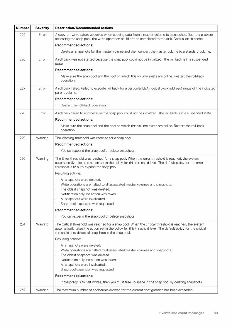
Number Severity Description/Recommended actions
225 Error A copy-on-write failure occurred when copying data from a master volume to a snapshot. Due to a problem accessing the snap pool, the write operation could not be completed to the disk. Data is left in cache.
Recommended actions:
• Delete all snapshots for the master volume and then convert the master volume to a standard volume.
226 Error A roll back was not started because the snap pool could not be initialized. The roll back is in a suspended state.
Recommended actions:
• Make sure the snap pool and the pool on which this volume exists are online. Restart the roll-back operation.
227 Error A roll back failed. Failed to execute roll back for a particular LBA (logical block address) range of the indicated parent volume.
Recommended actions:
• Restart the roll-back operation.
228 Error A roll back failed to end because the snap pool could not be initialized. The roll back is in a suspended state.
Recommended actions:
• Make sure the snap pool and the pool on which this volume exists are online. Restart the roll-back operation.
229 Warning The Warning threshold was reached for a snap pool.
Recommended actions:
• You can expand the snap pool or delete snapshots.
230 Warning The Error threshold was reached for a snap pool. When the error threshold is reached, the system automatically takes the action set in the policy for this threshold level. The default policy for the error threshold is to auto-expand the snap pool.
Resulting actions:
• All snapshots were deleted.• Write operations are halted to all associated master volumes and snapshots.• The oldest snapshot was deleted.• Notification only; no action was taken.• All snapshots were invalidated.• Snap-pool expansion was requested
Recommended actions:
• You can expand the snap pool or delete snapshots.
231 Warning The Critical threshold was reached for a snap pool. When the critical threshold is reached, the system automatically takes the action set in the policy for this threshold level. The default policy for the critical threshold is to delete all snapshots in the snap pool.
Resulting actions:
• All snapshots were deleted.• Write operations are halted to all associated master volumes and snapshots.• The oldest snapshot was deleted.• Notification only; no action was taken.• All snapshots were invalidated.• Snap-pool expansion was requested
Recommended actions:
• If the policy is to halt writes, then you must free up space in the snap pool by deleting snapshots.
232 Warning The maximum number of enclosures allowed for the current configuration has been exceeded.
Events and event messages 89

Number Severity Description/Recommended actions
The platform does not support the number of enclosures that are configured. The enclosure indicated by this event has been removed from the configuration.
Recommended actions:
• Reconfigure the system.
233 Warning The indicated disk type is invalid and is not allowed in the current configuration.
All disks of the disallowed type have been removed from the configuration.
Recommended actions:
• Replace the disallowed disks with ones that are supported.
234 Error A snap pool had a fatal error and is no longer useable.
Recommended actions:
• All the snapshots associated with this snap pool are invalid and you may want to delete them. However, the data in the master volume can be recovered by converting it to a standard volume.
235 Error An enclosure management processor (EMP) detected a serious error.
Recommended actions:
• Replace the indicated controller module or expansion module.
Info. An enclosure management processor (EMP) reported an event.
Recommended actions:
• No action is required.
236 Error A special shutdown operation has started. These special shutdown types indicate an incompatible feature.
Recommended actions:
• Replace the indicated controller module with one that supports the indicated feature.
Info. A special shutdown operation has started. These special shutdown types are used as part of the firmware-update process.
Recommended actions:
• No action is required.
237 Error A firmware update attempt was aborted because of either general system health issues, or unwritable cache data that would be lost during a firmware update.
Recommended actions:
• Resolve before retrying a firmware update. For health issues, issue the CLI show system command to determine the specific health issues. For unwritten cache data, use the CLI show unwritable-cache command
Info. A firmware update has started and is in progress. This event provides details of the steps in a firmware-update operation that may be of interest if you have problems updating firmware.
Recommended actions:
• No action is required.
238 Warning An attempt to install a licensed feature failed due to an invalid license.
Recommended actions:
• Check the license for what is allowed for the platform, make corrections as appropriate, and reinstall.
239 Warning A timeout occurred while flushing the CompactFlash.
Recommended actions:
• Restart the Storage Controller that logged this event.• If this event is logged again, shut down the Storage Controller and replace the CompactFlash.
90 Events and event messages

Number Severity Description/Recommended actions
240 Warning A failure occurred while flushing the CompactFlash.
Recommended actions:
• Restart the Storage Controller that logged this event.• If this event is logged again, shut down the Storage Controller and replace the CompactFlash.• If this event is logged again, shut down the Storage Controller and replace the controller module.
241 Info. The auto-write-through trigger event that caused event 242 to be logged has been resolved.
Recommended actions:
• No action is required.
242 Error The CompactFlash card in the controller module has failed.
This change met a condition to trigger the auto-write-through feature, which has disabled write-back cache and put the system in write-through mode. When the fault is resolved, event 241 is logged to indicate that write-back mode has been restored.
Recommended actions:
• If event 241 has not been logged since this event was logged, the CompactFlash probably does not have health of OK and the cause should be investigated. Another CompactFlash event was probably logged at approximately the same time as this event (such as event 239, 240, or 481). See the recommended actions for that event.
243 Info. A new controller enclosure has been detected. This happens when a controller module is moved from one enclosure to another and the controller detects that the midplane WWN is different from the WWN it has in its local flash.
Recommended actions:
• No action is required.
245 Info. An existing disk channel target device is not responding to SCSI discovery commands.
Recommended actions:
• Check the indicated target device for bad hardware or bad cable, then initiate a rescan.
246 Warning The coin battery is not present, is not properly seated, or has reached end-of-life.
The battery provides backup power for the real-time (date/time) clock. In the event of a power failure, the date and time will revert to 1980-01-01 00:00:00.
Recommended actions:
• Replace the controller module that logged this event.
247 Warning The FRU ID SEEPROM for the indicated field replaceable unit (FRU) cannot be read. FRU ID data might not be programmed.
FRU ID data includes the worldwide name, serial numbers, firmware and hardware versions, branding information, etc. This event is logged once each time a Storage Controller (SC) is started for each FRU that is not programmed.
Recommended actions:
• Return the FRU to have its FRU ID data reprogrammed.
248 Info. A valid feature license was successfully installed. See event 249 for details about each licensed feature.
Recommended actions:
• No action is required.
249 Info. After a valid license is installed, this event is logged for each licensed feature to show the new license value for that feature. The event specifies whether the feature is licensed, whether the license is temporary, and whether the temporary license is expired.
Recommended actions:
Events and event messages 91

Number Severity Description/Recommended actions
• No action is required.
250 Warning A license could not be installed.
The license is invalid or specifies a feature that is not supported on your product.
Recommended actions:
• Review the readme file that came with the license. Verify that you are trying to install the license in the system that the license was generated for.
251 Info. A volume-copy operation has started for the indicated source volume.
Do not mount either volume until the copy is complete (as indicated by event 268).
Recommended actions:
• No action is required.
252 Info. Data written to a snapshot after it was created has been deleted.
The snapshot now represents the state of the parent volume when the snapshot was created.
Recommended actions:
• No action is required.
253 Info. A license was uninstalled.
Recommended actions:
• No action is required.
255 Info. The PBCs across controllers do not match as PBC from controller A and PBC from controller B are from different vendors.
This may limit the available configurations.
Recommended actions:
• No action is required.
256 Info. A snapshot was created for a volume but it has not been committed yet.
An internal snapshot was created for a virtual replication volume but it has not been committed yet.
This can occur when a snapshot is taken by an application, such as the VSS hardware provider, that is timing-sensitive and needs to take a snapshot in two stages. After the snapshot is committed and event 258 is logged, the snapshot can be used.
Recommended actions:
• No action is required.
257 Info. The indicated snapshot has been prepared and committed and is ready for use.
Recommended actions:
• No action is required.
258 Info A snapshot was committed for a volume. The snapshot is now ready for use.
Recommended actions:
• No action is required.
259 Info. In-band CAPI commands have been disabled.
Recommended actions:
• No action is required.
260 Info. In-band CAPI commands have been enabled.
Recommended actions:
92 Events and event messages

Number Severity Description/Recommended actions
• No action is required.
261 Info. In-band SES commands have been disabled.
Recommended actions:
• No action is required.
262 Info. In-band SES commands have been enabled.
Recommended actions:
• No action is required.
263 Warning The indicated spare disk is missing. Either it was removed or it is not responding.
Recommended actions:
• Replace the disk with one of the same type (SSD, enterprise SAS, or midline SAS) and the same or greater capacity.
• Configure the disk as a spare.
266 Info. A volume-copy operation for the indicated master volume has been aborted by a user.
Recommended actions:
• No action is required.
267 Error A volume-copy operation completed with a failure.
This event has two variants:
1. If the source volume is a master volume, you can remount it. If the source volume is a snapshot, do not remount it until the copy is complete (as indicated by event 268).
2. Possible causes are the pool running out of available space and crossing the high threshold, volumes being unavailable, or general I/O errors.
Recommended actions:
• For variant 1: No action is required.• For variant 2: Look for other events logged at approximately the same time that indicate a pool space or
volume failure. Follow the recommended actions for those events.
268 Info. A volume-copy operation for the indicated volume has completed.
Recommended actions:
• No action is required.
269 Error A partner firmware update operation could not be performed.
This event has these variants:
1. System health is insufficient to support firmware partner update.2. System has unwritable cache data present.3. Unable to determine if unwritable cache data is present.4. Incompatible firmware versions in the controller modules.5. Incompatible firmware is present in the system.
Recommended actions:
• For variant 1, 2, or 3: You must resolve this condition before the firmware update will proceed. Log into the system and run the show system command to identify unhealthy components and find recommendations for restoring system health. The check firmware-upgrade-health command can be used to verify that the system is ready for firmware upgrade. For unwritten cache data, use the CLI show unwritable-cache command.
• For variant 4: This feature can be manually re-enabled after both controller modules are running compatible firmware.
• For variant 5: The controller modules should be updated to the latest version of firmware.
Events and event messages 93
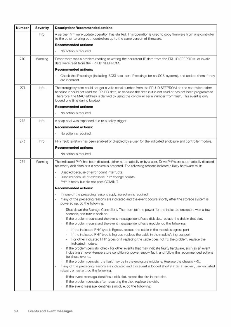
Number Severity Description/Recommended actions
Info. A partner firmware update operation has started. This operation is used to copy firmware from one controller to the other to bring both controllers up to the same version of firmware.
Recommended actions:
• No action is required.
270 Warning Either there was a problem reading or writing the persistent IP data from the FRU ID SEEPROM, or invalid data were read from the FRU ID SEEPROM.
Recommended actions:
• Check the IP settings (including iSCSI host-port IP settings for an iSCSI system), and update them if they are incorrect.
271 Info. The storage system could not get a valid serial number from the FRU ID SEEPROM on the controller, either because it could not read the FRU ID data, or because the data in it is not valid or has not been programmed. Therefore, the MAC address is derived by using the controller serial number from flash. This event is only logged one time during bootup.
Recommended actions:
• No action is required.
272 Info. A snap pool was expanded due to a policy trigger.
Recommended actions:
• No action is required.
273 Info. PHY fault isolation has been enabled or disabled by a user for the indicated enclosure and controller module.
Recommended actions:
• No action is required.
274 Warning The indicated PHY has been disabled, either automatically or by a user. Drive PHYs are automatically disabled for empty disk slots or if a problem is detected. The following reasons indicate a likely hardware fault:
• Disabled because of error count interrupts• Disabled because of excessive PHY change counts• PHY is ready but did not pass COMINIT
Recommended actions:
• If none of the preceding reasons apply, no action is required.• If any of the preceding reasons are indicated and the event occurs shortly after the storage system is
powered up, do the following:
• Shut down the Storage Controllers. Then turn off the power for the indicated enclosure wait a few seconds, and turn it back on.
• If the problem recurs and the event message identifies a disk slot, replace the disk in that slot.• If the problem recurs and the event message identifies a module, do the following:
• If the indicated PHY type is Egress, replace the cable in the module's egress port• If the indicated PHY type is Ingress, replace the cable in the module's ingress port• For other indicated PHY types or if replacing the cable does not fix the problem, replace the
indicated module.• If the problem persists, check for other events that may indicate faulty hardware, such as an event
indicating an over-temperature condition or power supply fault, and follow the recommended actions for those events.
• If the problem persists, the fault may be in the enclosure midplane. Replace the chassis FRU.• If any of the preceding reasons are indicated and this event is logged shortly after a failover, user-initiated
rescan, or restart, do the following:
• If the event message identifies a disk slot, reseat the disk in that slot.• If the problem persists after reseating the disk, replace the disk.• If the event message identifies a module, do the following:
94 Events and event messages

Number Severity Description/Recommended actions
• If the indicated PHY type is Egress, replace the cable in the module's egress port.• If the indicated PHY type is Ingress, replace the cable in the module's ingress port.• For other indicated PHY types or if replacing the cable does not fix the problem, replace the
indicated module.• If the problem persists, check for other events that may indicate faulty hardware, such as an event
indicating an over-temperature condition or power supply fault, and follow the recommended actions for those events.
• If the problem persists, the fault may be in the enclosure midplane. Replace the chassis FRU.
275 Info. The indicated PHY has been enabled.
Recommended actions:
• No action is required.
276 Info. A mirror set was created.
Recommended actions:
• No action is required.
277 Info. A mirror set was deleted.
Recommended actions:
• No action is required.
278 Info. A mirror set was verified.
Recommended actions:
• No action is required.
279 Info. A mirror component break command completed.
Recommended actions:
• No action is required.
280 Info. A mirror component split command completed.
Recommended actions:
• No action is required.
281 Info. A mirror set join command completed.
Recommended actions:
• No action is required.
282 Info. A mirror component rejoin command completed.
Recommended actions:
• No action is required.
283 Info. A mirror component resilver command completed.
Recommended actions:
• No action is required.
284 Info. A mirror component of a mirror set was deleted.
Recommended actions:
• No action is required.
285 Info. A scoreboard store is no longer usable.
Recommended actions:
• No action is required.
Events and event messages 95

Number Severity Description/Recommended actions
286 Info. Verify was started for a mirror component.
Recommended actions:
• No action is required.
287 Info. Verify completed for a mirror component.
Recommended actions:
• No action is required.
288 Info. Verify was aborted for a mirror component.
Recommended actions:
• No action is required.
289 Info. Verify failed for mirror component.
Recommended actions:
• No action is required.
290 Info. An I/O error occurred for a mirror component.
Recommended actions:
• No action is required.
291 Info. Silvering was started for a mirror component.
Recommended actions:
• No action is required.
292 Info. ilvering completed for a mirror component.
Recommended actions:
• No action is required.
293 Info. Silvering was aborted for a mirror component.
Recommended actions:
• No action is required.
294 Info. A break command completed for a mirror component.
Recommended actions:
• No action is required.
295 Info. A split command completed.
Recommended actions:
• No action is required.
296 Info. A join command completed.
Recommended actions:
• No action is required.
297 Info. A rejoin command completed.
Recommended actions:
• No action is required.
298 Warning The real-time clock (RTC) setting on the controller is invalid.
This event will most commonly occur after a power loss if the real-time clock battery has failed. The time may have been set to a time that is up to 5 minutes before the power loss occurred, or it may have been reset to 1980-01-01 00:00:00.
96 Events and event messages

Number Severity Description/Recommended actions
Recommended actions:
• Check the system date and time. If either is incorrect, set them to the correct date and time.• Also look for event 246 and follow the recommended action for that event.
When the problem is resolved, event 299 is logged.
299 Info. The RTC setting on the controller was successfully recovered.
This event will most commonly occur after an unexpected power loss.
Recommended actions:
• No action is required, but if event 246 is also logged, follow the recommended action for that event.
300 Info. CPU frequency has changed to high.
Recommended actions:
• No action is required.
301 Info. CPU frequency has changed to low.
Recommended actions:
• No action is required.
302 Info. DDR memory clock frequency has changed to high.
Recommended actions:
• No action is required.
303 Info. DDR memory clock frequency has changed to low.
Recommended actions:
• No action is required.
304 Info. The controller has detected I2C errors that may have been fully recovered.
Recommended actions:
• No action is required.
305 Info. A serial number in Storage Controller (SC) flash memory was found to be invalid when compared to the serial number in the controller-module or midplane FRU ID SEEPROM. The valid serial number has been recovered automatically.
Recommended actions:
• No action is required.
306 Info. The controller-module serial number in Storage Controller (SC) flash memory was found to be invalid when compared to the serial number in the controller-module FRU ID SEEPROM. The valid serial number has been recovered automatically.
Recommended actions:
• No action is required.
307 Critical A temperature sensor on a controller FRU detected an over-temperature condition that caused the controller to shut down.
Recommended actions:
• Check that the storage system’s fans are running.• Check that the ambient temperature is not too warm. The controller enclosure operating range is 5°C to
35°C (41°F to 95°F). The expansion enclosure operating range is 5°C to 40°C (41°F to 104°F).• Check for any obstructions to the airflow.• Check that there is a module or blank plate in every module slot in the enclosure.
If the problem persists, replace the controller module that logged the error.
Events and event messages 97

Number Severity Description/Recommended actions
309 Info. Normally when the Management Controller (MC) is started, the IP data is obtained from the midplane FRU ID SEEPROM where it is persisted. If the system is unable to write it to the SEEPROM the last time it changed, a flag is set in flash memory. This flag is checked during startup, and if set, this event is logged and the IP data that is in flash memory is used. The only time that this would not be the correct IP data would be if the controller module was swapped and then whatever data are in the controller’s flash memory is used.
Recommended actions:
• No action is required.
310 Info. After a rescan, back-end discovery and initialization of data for at least one EMP (Enclosure Management Processor) has completed. This event is not logged again when processing completes for other EMPs in the system.
Recommended actions:
• No action is required.
311 Info. This event is logged when a user initiates a ping of a host using the iSCSI interface.
Recommended actions:
• If the ping operation failed, check connectivity between the storage system and the remote host.
312 Info. This event is used by email messages and SNMP traps when testing notification settings. This event is not recorded in the event log.
Recommended actions:
• No action is required.
313 Error The indicated controller module has failed. This event can be ignored for a single-controller configuration.
Recommended actions:
• If this is a dual-controller system, replace the failed controller module. The module’s Fault/Service Required LED will be illuminated (not blinking).
314 Error The indicated FRU has failed or is not operating correctly. This event follows some other FRU-specific event indicating a problem.
Recommended actions:
• To determine whether the FRU needs to be replaced, see the topic about verifying component failure in your product's Hardware Installation and Maintenance Guide.
315 Critical This IOM is incompatible with the enclosure in which it is inserted.
Recommended actions:
• Replace this IOM with an IOM that is compatible with this enclosure.
316 Warning The temporary license for a feature has expired.
Any components created with the feature remain accessible but new components cannot be created.
Recommended actions:
• To continue using the feature, purchase a permanent license.
Info. The temporary license for a feature will expire in 10 days. Any components created with the feature will remain accessible but new components cannot be created.
Recommended actions:
• To continue using the feature after the trial period, purchase a permanent license.
317 Error A serious error has been detected on the Storage Controller disk interface. The controller will be killed by its partner.
Recommended actions:
• Visually trace the cabling between the controller modules and expansion modules.
98 Events and event messages

Number Severity Description/Recommended actions
• If the cabling is OK, replace the controller module that logged this event.• If the problem recurs, replace the expansion module that is connected to the controller module.
319 Warning The indicated available disk has failed.
Recommended actions:
• Replace the disk with one of the same type (SSD, enterprise SAS, or midline SAS) and the same or greater capacity. For continued optimum I/O performance, the replacement disk should have performance that is the same as or better than the one it is replacing.
322 Warning The controller has an older Storage Controller (SC) version than the version used to create the CHAP authentication database in the controller’s flash memory.
The CHAP database cannot be read or updated. However, new records can be added, which will replace the existing database with a new database using the latest known version number.
Recommended actions:
• Upgrade the controller firmware to a version whose SC is compatible with the indicated database version.
• If no records were added, the database becomes accessible and remains intact.• If records were added, the database becomes accessible but contains only the new records.
352 Info. Expander Controller (EC) assert data or stack-dump data are available.
Recommended actions:
• No action is required.
353 Info. Expander Controller (EC) assert data and stack-dump data have been cleared.
Recommended actions:
• No action is required.
354 Warning SAS topology has changed on a host port. At least one PHY has gone down. For example, the SAS cable connecting a controller host port to a host has been disconnected.
Recommended actions:
• Check the cable connection between the indicated port and the host.• Monitor the log to see if the problem persists.
Info. SAS topology has changed on a host port. At least one PHY has become active. For example, the SAS cable connecting a controller host port to a host has been connected.
Recommended actions:
• No action is required.
356 Warning This event can only result from tests that are run in the manufacturing environment.
Recommended actions:
• Follow the manufacturing process.
357 Warning This event can only result from tests that are run in the manufacturing environment.
Recommended actions:
• Follow the manufacturing process.
358 Critical All PHYs are down for the indicated disk channel. The system is degraded and is not fault tolerant because all disks are in a single-ported state.
Recommended actions:
• Turn off the power for the controller enclosure, wait a few seconds, and turn it back on.• If event 359 has been logged for the indicated channel, indicating the condition no longer exists, no
further action is required.
Events and event messages 99

Number Severity Description/Recommended actions
• If the condition persists, this indicates a hardware problem in one of the controller modules or in the controller enclosure midplane. For help identifying which FRU to replace, see Troubleshooting and problem solving.
Warning Some, but not all, PHYs are down for the indicated disk channel.
Recommended actions:
• Monitor the log to see whether the condition persists.• If event 359 has been logged for the indicated channel, indicating the condition no longer exists, no
further action is required.• If the condition persists, this indicates a hardware problem in one of the controller modules or in the
controller enclosure midplane. For help identifying which FRU to replace, see Troubleshooting and problem solving.
359 Info. All PHYs that were down for the indicated disk channel have recovered and are now up.
Recommended actions:
• No action is required.
360 Info. The speed of the indicated disk PHY was renegotiated.
Recommended actions:
• No action is required.
361 Critical, Error, or Warning
The scheduler experienced a problem with the indicated schedule.
Recommended actions:
• Take appropriate action based on the indicated problem.
Info. A scheduled task was initiated.
Recommended actions:
• No action is required.
362 Critical, Error, or Warning
The scheduler experienced a problem with the indicated task.
Recommended actions:
• Take appropriate action based on the indicated problem.
Info. The scheduler experienced a problem with the indicated task.
Recommended actions:
• No action is required.
363 Error When the Management Controller (MC) is restarted, firmware versions that are currently installed are compared against those in the bundle that was most recently installed. When firmware is updated, it is important that all components are successfully updated or the system may not work correctly. Components checked include the CPLD, Expander Controller (EC), Storage Controller (SC), and MC.
Recommended actions:
• Reinstall the firmware bundle.
Info. When the Management Controller (MC) is restarted, firmware versions that are currently installed are compared against those in the bundle that was most recently installed. If the versions match, this event is logged as Informational severity. Components checked include the CPLD, Expander Controller (EC), Storage Controller (SC), and MC.
Recommended actions:
• No action is required.
364 Info. The broadcast bus is running as generation 1.
Recommended actions:
100 Events and event messages

Number Severity Description/Recommended actions
• No action is required.
365 Error An uncorrectable ECC error occurred in Storage Controller CPU memory more than once, indicating a probable hardware fault.
Recommended actions:
• Replace the controller module that logged this event.
Warning An uncorrectable ECC error occurred in Storage Controller CPU memory.
This event is logged with Warning severity to provide information that may be useful to technical support, but no action is required now. It will be logged with Error severity if it is necessary to replace the controller module.
Recommended actions:
• No action is required.
Events (continued)Number Severity Description/Recommended actions
400 Info. The indicated log has filled to a level at which it needs to be transferred to a log-collection system.
Recommended actions:
• No action is required.
401 Warning The indicated log has filled to a level at which diagnostic data will be lost if not transferred to a log-collection system.
Recommended actions:
• Transfer the log file to the log-collection system.
402 Error The indicated log has wrapped and has started to overwrite its oldest diagnostic data.
Recommended actions:
• Investigate why the log-collection system is not transferring the logs before they are overwritten. For example, you might have enabled managed logs without configuring a destination to send logs to.
412 Warning One disk in the indicated RAID-6 disk group failed. The disk group is online but has a status of FTDN (fault tolerant with a down disk).
If a dedicated spare (linear only) or global spare of the proper type and size is present, that spare is used to automatically reconstruct the disk group. Events 9 and 37 are logged to indicate this. If no usable spare disk is present, but an available disk of the proper type and size is present and the dynamic spares feature is enabled, that disk is used to automatically reconstruct the disk group and event 37 is logged.
Recommended actions:
RAID-6:
• If event 37 was not logged, a spare of the proper type and size was not available for reconstruction. Replace the failed disk with one of the same type and the same or greater capacity and, if necessary, designate it as a spare. Confirm this by checking that events 9 and 37 are logged.
• Otherwise, reconstruction automatically started and event 37 was logged. Replace the failed disk and configure the replacement as a dedicated spare (linear only) or global spare for future use.
• For continued optimum I/O performance, the replacement disk should have the same or better performance.
• Confirm that all failed disks have been replaced and that there are sufficient spare disks configured for future use.
ADAPT:
Events and event messages 101

Number Severity Description/Recommended actions
• If event 37 was not logged, spare space was not available for reconstruction. Replace the failed disk with one of the same type and the same or greater capacity. Reconstruction should start and event 37 should be logged automatically.
• For continued optimum I/O performance, the replacement disk should have the same or better performance.
• Confirm that all failed disks have been replaced for future fault tolerance.
413 Info. A request to create a replication set completed successfully.
Recommended actions:
• No action is required.
414 Error A request to create a replication set failed.
This operation is not permitted if the specified volume is already in a replication set or is not a master volume.
Recommended actions:
• If the volume is a master volume and is not in a replication set, retry the operation.
415 Info. A request to delete a replication set completed successfully.
Recommended actions:
• No action is required.
416 Error A request to delete a replication set failed.
This can occur if an invalid identifier was specified for the replication set, or if the specified primary volume is not in the local system.
Recommended actions:
• Repeat the deletion using a valid replication-set identifier, or on the local system for the primary volume.
417 Info. A snapshot was deleted.
• To make space for a remote snapshot proxy volume.• To make space for a new snapshot.• While changing a secondary volume to a primary volume.• To make space for a new snapshot because the maximum number of snapshots per volume was reached.• To make space for a new snapshot because the maximum number of replication snapshots per system
was reached.• To make space for an unknown reason.
A virtual snapshot was deleted because the user-specified snapshot space limit was exceeded.
Recommended actions:
• No action is required.
418 Warning A remote snapshot operation failed.
• Because the remote pool volume limit was reached.• Because the remote controller volume limit was reached.• Because the remote pool volume limit was reached.• Because of an unknown reason.
A replication operation cannot complete because it needs to create a proxy volume and a replication snapshot in the secondary pool, but the maximum number of volumes exists for that pool or its owning controller and the pool contains no suitable snapshot to automatically delete.
This event is logged in the secondary volume's system only.
Recommended actions:
• To enable the replication operation to continue, delete at least one unneeded volume from the destination pool or from another pool owned by the same controller. After performing the above action, if the
102 Events and event messages

Number Severity Description/Recommended actions
replication fails for the same reason and becomes suspended, events 431 and 418 will be logged. Repeat the above action and resume the replication.
• To allow additional volumes to be created in the future (standard volumes, replication volumes, or snapshots), delete any unneeded volumes.
419 Info. A request to add a secondary volume started.
Recommended actions:
• No action is required.
420 Error A request to add a secondary volume failed.
This can occur for several reasons, such as:
• The volume is already a replication volume.• The volume is not local to the system.• The communication link is busy or experienced an error.• The volume is not the same size as the existing volume or is no longer in the set.• The volume record is not up to date.• Replication is not licensed or the license limit would be exceeded.
Recommended actions:
• If any of the above problems exist, resolve them. Then repeat the add operation with a valid volume.
421 Info. A request to add a secondary volume completed successfully.
Recommended actions:
• No action is required.
422 Info. A request to remove a secondary volume completed successfully.
Recommended actions:
• No action is required.
423 Error A request to remove a secondary volume failed.
This can occur for several reasons, such as:
• The volume record is not found.• The volume record is not yet available.• A primary volume conflict exists.• You cannot delete the volume from a remote system.• You cannot remove the volume because it is the primary volume.
Recommended actions:
• If any of the above problems exist, resolve them. Then repeat the remove operation with a valid volume.
424 Info. A request to modify a secondary volume completed successfully.
Recommended actions:
• No action is required.
425 Info. A replication started.
Recommended actions:
• No action is required.
426 Info. A replication completed successfully.
Recommended actions:
• No action is required.
427 Warning • An attempt by a primary volume to send a local configuration tag to a remote volume failed.
Events and event messages 103
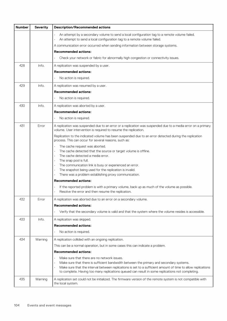
Number Severity Description/Recommended actions
• An attempt by a secondary volume to send a local configuration tag to a remote volume failed.• An attempt to send a local configuration tag to a remote volume failed.
A communication error occurred when sending information between storage systems.
Recommended actions:
• Check your network or fabric for abnormally high congestion or connectivity issues.
428 Info. A replication was suspended by a user.
Recommended actions:
• No action is required.
429 Info. A replication was resumed by a user.
Recommended actions:
• No action is required.
430 Info. A replication was aborted by a user.
Recommended actions:
• No action is required.
431 Error A replication was suspended due to an error or a replication was suspended due to a media error on a primary volume. User intervention is required to resume the replication.
Replication to the indicated volume has been suspended due to an error detected during the replication process. This can occur for several reasons, such as:
• The cache request was aborted.• The cache detected that the source or target volume is offline.• The cache detected a media error.• The snap pool is full.• The communication link is busy or experienced an error.• The snapshot being used for the replication is invalid.• There was a problem establishing proxy communication.
Recommended actions:
• If the reported problem is with a primary volume, back up as much of the volume as possible.• Resolve the error and then resume the replication.
432 Error A replication was aborted due to an error on a secondary volume.
Recommended actions:
• Verify that the secondary volume is valid and that the system where the volume resides is accessible.
433 Info. A replication was skipped.
Recommended actions:
• No action is required.
434 Warning A replication collided with an ongoing replication.
This can be a normal operation, but in some cases this can indicate a problem.
Recommended actions:
• Make sure that there are no network issues.• Make sure that there is sufficient bandwidth between the primary and secondary systems.• Make sure that the interval between replications is set to a sufficient amount of time to allow replications
to complete. Having too many replications queued can result in some replications not completing.
435 Warning A replication set could not be initialized. The firmware version of the remote system is not compatible with the local system.
104 Events and event messages

Number Severity Description/Recommended actions
Recommended actions:
• Update the firmware on one or both systems so they are running the same version.• Check your network or fabric for abnormally high congestion or connectivity issues.
436 Warning Firmware in the remote system is incompatible with firmware in the local system so they cannot communicate with each other to perform replication operations.
Recommended actions:
• Update the firmware on one or both systems so they are running the same version.
437 Info. A request by a user to change the primary volume of a replication set was started.
Recommended actions:
• No action is required.
438 Info. A request by a user to change the primary volume of a replication set completed successfully.
Recommended actions:
• No action is required.
439 Error A request to change a primary volume failed.
This can occur for several reasons, such as:
• The volume is not in the replication set.• Configuration tag or configuration data not found.• The retry limit has been reached.
Recommended actions:
• Verify that the specified volume is part of the replication set.• Verify that there are no network issues preventing communication between the local and remote storage
systems.
440 Warning A replication is being retried due to an error in the secondary volume.
This can occur for several reasons, such as:
• The cache request was aborted.• The cache detected that the source or target volume is offline.• The cache detected a media error.• The snap pool is full.• The communication link is busy or experienced an error.• The snapshot being used for the replication is invalid.• There was a problem establishing proxy communication.• The replication is being automatically retried according to policies in place. If the issue is resolved before
retries are exhausted, the replication will continue on its own. Otherwise, it will go into a suspended state unless the policy is set up to retry forever.
Recommended actions:
• If any of the above problems exist, resolve them.
441 Error A request to add a secondary volume failed. User intervention is needed to remove the volume from the set.
Recommended actions:
• Remove the indicated secondary volume from the replication set.
442 Warning Power-On Self Test (POST) diagnostics detected a hardware error in a UART chip.
Recommended actions:
• Replace the controller module that logged this event.
443 Error The firmware for the indicated enclosure is not supported in this configuration.
Events and event messages 105

Number Severity Description/Recommended actions
The firmware for the indicated enclosure does not support this enclosure for use as an expansion chassis. Its firmware supports this enclosure only as a direct attached JBOD.
Recommended actions:
• Replace the indicated enclosure. It is not supported.
444 Info. A snap pool is running out of space.
A snap pool reached a capacity threshold and the associated policy completed successfully:
• Delete snapshots• Halt writes• Delete oldest snapshot• Notify only• Invalidate snapshots• Auto expand• Unknown policy
For example, the snap pool was expanded successfully, or the oldest snapshot was deleted, or all snapshots were deleted. If the policy is Delete Oldest Snapshot, the serial number of the deleted snapshot is reported.
Recommended actions:
• No action is required.
Warning A snap pool is running out of space.
A snap pool reached a capacity threshold and the associated Auto Expand policy failed because there is not enough available space in the disk group.
Recommended actions:
• Increase the available space in the disk group either by expanding the disk group or by removing any unneeded volumes.
449 Info. A roll back was aborted because of an error or other internally detected condition.
This can occur if a roll back is in progress and a user selects to roll back a different volume, which will abort the first roll back and start a new roll back. A user can't explicitly abort a roll back because that would corrupt the parent volume.
Recommended actions:
• No action is required.
450 Warning The status of a remote volume changed from online to offline.
This can occur for several reasons, such as:
• The communication link is busy or experienced an error.• The local initiator experienced an error.
Recommended actions:
• Verify that there are no network issues preventing communication between the local and remote storage systems.
451 Info. The status of a remote volume changed from offline to online.
Recommended actions:
• No action is required.
452 Info. A remote volume was successfully detached from a replication set.
The volume can now be physically moved to another storage system.
Recommended actions:
• No action is required.
453 Info. A remote volume was successfully reattached to a replication set.
106 Events and event messages
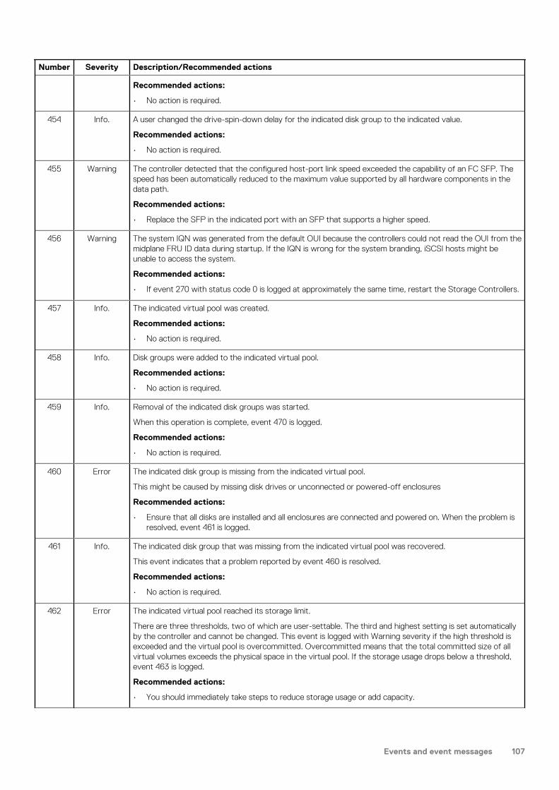
Number Severity Description/Recommended actions
Recommended actions:
• No action is required.
454 Info. A user changed the drive-spin-down delay for the indicated disk group to the indicated value.
Recommended actions:
• No action is required.
455 Warning The controller detected that the configured host-port link speed exceeded the capability of an FC SFP. The speed has been automatically reduced to the maximum value supported by all hardware components in the data path.
Recommended actions:
• Replace the SFP in the indicated port with an SFP that supports a higher speed.
456 Warning The system IQN was generated from the default OUI because the controllers could not read the OUI from the midplane FRU ID data during startup. If the IQN is wrong for the system branding, iSCSI hosts might be unable to access the system.
Recommended actions:
• If event 270 with status code 0 is logged at approximately the same time, restart the Storage Controllers.
457 Info. The indicated virtual pool was created.
Recommended actions:
• No action is required.
458 Info. Disk groups were added to the indicated virtual pool.
Recommended actions:
• No action is required.
459 Info. Removal of the indicated disk groups was started.
When this operation is complete, event 470 is logged.
Recommended actions:
• No action is required.
460 Error The indicated disk group is missing from the indicated virtual pool.
This might be caused by missing disk drives or unconnected or powered-off enclosures
Recommended actions:
• Ensure that all disks are installed and all enclosures are connected and powered on. When the problem is resolved, event 461 is logged.
461 Info. The indicated disk group that was missing from the indicated virtual pool was recovered.
This event indicates that a problem reported by event 460 is resolved.
Recommended actions:
• No action is required.
462 Error The indicated virtual pool reached its storage limit.
There are three thresholds, two of which are user-settable. The third and highest setting is set automatically by the controller and cannot be changed. This event is logged with Warning severity if the high threshold is exceeded and the virtual pool is overcommitted. Overcommitted means that the total committed size of all virtual volumes exceeds the physical space in the virtual pool. If the storage usage drops below a threshold, event 463 is logged.
Recommended actions:
• You should immediately take steps to reduce storage usage or add capacity.
Events and event messages 107

Number Severity Description/Recommended actions
Warning The indicated virtual pool exceeded its high threshold for allocated pages, and the virtual pool is overcommitted.
There are three thresholds, two of which are user-settable. The third and highest setting is set automatically by the controller and cannot be changed. This event is logged with Warning severity if the high threshold is exceeded and the virtual pool is overcommitted. Overcommitted means that the total committed size of all virtual volumes exceeds the physical space in the virtual pool. If the storage usage drops below a threshold, event 463 is logged.
Recommended actions:
• You should immediately take steps to reduce storage usage or add capacity.
Info. The indicated virtual pool exceeded one of its thresholds for allocated pages.
There are three thresholds, two of which are user-settable. The third and highest setting is set automatically by the controller and cannot be changed. This event is logged with Warning severity if the high threshold is exceeded and the virtual pool is overcommitted. Overcommitted means that the total committed size of all virtual volumes exceeds the physical space in the virtual pool. If the storage usage drops below a threshold, event 463 is logged.
Recommended actions:
• No action is required for the low and mid thresholds. However, you may want to determine if your storage usage is growing at a rate that will result in the high threshold being crossed in the near future. If this will occur, either take steps to reduce storage usage or purchase additional capacity.
• If the high threshold is crossed, you should promptly take steps to reduce storage usage or add capacity.
463 Info. The indicated virtual pool has dropped below one of its thresholds for allocated pages.
This event indicates that a condition reported by event 462 is no longer applicable.
Recommended actions:
• No action is required.
464 Warning A user inserted an unsupported cable or SFP into the indicated controller host port.
Recommended actions:
• Replace the cable or SFP with a supported type.
465 Info. A user removed an unsupported cable or SFP from the indicated controller host port.
Recommended actions:
• No action is required.
466 Info. The indicated virtual pool was deleted.
Recommended actions:
• No action is required.
467 Info. Addition of the indicated disk group completed successfully.
Recommended actions:
• No action is required.
468 Info. FPGA temperature has returned to the normal operating range and the speed of buses connecting the FPGA to downstream adapters has been restored. The speed was reduced to compensate for an FPGA over-temperature condition.
This event indicates that a problem reported by event 469 is resolved.
Recommended actions:
• No action is required.
469 Warning The speed of buses connecting the FPGA to downstream adapters has been reduced to compensate for an FPGA over-temperature condition.
The storage system is operational but I/O performance is reduced.
108 Events and event messages

Number Severity Description/Recommended actions
Recommended actions:
• Check that the storage system’s fans are running.• Check that the ambient temperature is not too warm. The controller enclosure operating range is 5°C to
35°C (41°F to 95°F). The expansion enclosure operating range is 5°C to 40°C (41°F to 104°F).• Check for any obstructions to the airflow.• Check that there is a module or blank plate in every module slot in the enclosure.• If none of these recommended actions resolve the issue, replace the controller module that logged the
error.
When the problem is resolved, event 468 is logged.
470 Warning Removal of the indicated disk groups completed with failure.
Removal of disk groups can fail for several reasons, and the specific reason for this failure is included with the event. Removal most often fails because there is no longer room in the remaining pool space to move data pages off of the disks in the disk group.
Recommended actions:
• Resolve the issue specified by the error messaging included with this event and re-issue the request to remove the disk group.
Info. Removal of the indicated disk groups completed successfully.
Recommended actions:
• No action is required.
471 Error A replication was queued because the secondary volume is detached.
Recommended actions:
• To allow the replication to proceed, reattach the secondary volume and then resume the replication.
473 Info. The indicated volume is using more than its threshold percentage of its virtual pool.
This is an indication that the storage usage crossed the user-specified threshold for this volume. If the storage usage drops below the threshold, event 474 is logged.
Recommended actions:
• No action is required. How this information is utilized is left to the discretion of the user.
474 Info. The indicated volume is no longer using more than its threshold percentage of its virtual pool.
This event indicates that the condition reported by event 473 is no longer applicable.
Recommended actions:
• No action is required.
475 Info. Replication was queued because the secondary volume is in an offline state.
Recommended actions:
• To allow the replication to proceed, resolve the problem that is preventing access to the secondary volume.
476 Warning The CPU temperature exceeded the safe range so the CPU entered its self-protection state. IOPS were reduced.
The storage system is operational but I/O performance is reduced.
Recommended actions:
• Check that the storage system’s fans are running.• Check that the ambient temperature is not too warm. The controller enclosure operating range is 5°C to
35°C (41°F to 95°F). The expansion enclosure operating range is 5°C to 40°C (41°F to 104°F).• Check for any obstructions to the airflow.• Check that there is a module or blank plate in every module slot in the enclosure.
Events and event messages 109

Number Severity Description/Recommended actions
• If none of these recommended actions resolve the issue, replace the controller module that logged the error.
When the problem is resolved, event 478 is logged.
477 Info. The CPU temperature exceeded the normal range so the CPU speed was reduced. IOPS were reduced.
The storage system is operational but I/O performance is reduced.
Recommended actions:
• Check that the storage system’s fans are running.• Check that the ambient temperature is not too warm. The controller enclosure operating range is 5°C to
35°C (41°F to 95°F). The expansion enclosure operating range is 5°C to 40°C (41°F to 104°F).• Check for any obstructions to the airflow.• Check that there is a module or blank plate in every module slot in the enclosure.• If none of these recommended actions resolve the issue, replace the controller module that logged the
error.
When the problem is resolved, event 478 is logged.
478 Info. A problem reported by event 476 or 477 is resolved.
Recommended actions:
• No action is required.
479 Error The controller reporting this event was unable to flush data to or restore data from non-volatile memory.
This mostly likely indicates a CompactFlash failure, but it could be caused by some other problem with the controller module. The Storage Controller that logged this event will be killed by its partner controller, which will use its own copy of the data to perform the flush or restore operation.
Recommended actions:
• If this is the first time this event has been logged, restart the killed Storage Controller.• If this event is then logged again, replace the CompactFlash.• If this event is then logged again, shut down the Storage Controller and replace the controller module.
480 Error An IP address conflict was detected for the indicated iSCSI port of the storage system. The indicated IP address is already in use.
Recommended actions:
• Contact your data-network administrator to help resolve the IP address conflict.
481 Error The periodic monitor of CompactFlash hardware detected an error. The controller was put in write-through mode, which reduces I/O performance.
Recommended actions:
• Restart the Storage Controller that logged this event.• If this event is logged again, shut down the Storage Controller and replace the CompactFlash.• If this event is logged again, shut down the Storage Controller and replace the controller module.
482 Warning One of the PCIe buses is running with fewer lanes than it should.
This event is the result of a hardware problem that has caused the controller to use fewer lanes. The system works with fewer lanes, but I/O performance is degraded.
Recommended actions:
• Replace the controller module that logged this event.
483 Error An invalid expansion-module connection was detected for the indicated disk channel. An egress port is connected to an egress port, or an ingress port is connected to an incorrect egress port.
Recommended actions:
• Visually trace the cabling between enclosures and correct the cabling.
110 Events and event messages

Number Severity Description/Recommended actions
484 Warning No compatible spares are available to reconstruct this disk group if it experiences a disk failure. Only disk groups that have dedicated or suitable global spares will start reconstruction automatically.
This situation puts data at increased risk because it will require user action to configure a disk as a dedicated or global spare before reconstruction can begin on the indicated disk group if a disk in that disk group fails in the future.
If the last global spare has been deleted or used for reconstruction, ALL disk groups that do not have at least one dedicated or global spare are at increased risk. Note that even though there may be global spares still available, they cannot be used for reconstruction of a disk group if that disk group uses larger-capacity disks or a different type of disk. Therefore, this event may be logged even when there are unused global spares. If the dynamic spares feature is enabled, this event will be logged even if there is an available disk that may be used for reconstruction.
Recommended actions:
• Configure disks as dedicated spares or global spares.
• For a dedicated spare, the disk must be of the same type as the other disks in the linear disk group and at least as large as the smallest-capacity disk in the linear disk group, and it should have the same or better performance.
• For a global spare, it is best to choose a disk that is as big as or bigger than the largest disk of its type in the system and of equal or greater performance. If the system contains a mix of disk types (SSD, enterprise SAS, or midline SAS), there should be at least one global spare of each type (unless dedicated spares are used to protect every disk group of a given type, which will only apply to a linear storage configuration).
485 Warning The indicated disk group was quarantined to prevent writing invalid data that may exist in the controller that logged this event.
This event is logged to report that the indicated disk group has been put in the quarantined offline state (status of QTOF) to prevent loss of data. The controller that logged this event has detected (using information saved in the disk group metadata) that it may contain outdated data that should not be written to the disk group. Data may be lost if you do not follow the recommended actions carefully. This situation is typically caused by removal of a controller module without shutting it down first, then inserting a different controller module in its place. To avoid having this problem occur in the future, always shut down the Storage Controller in a controller module before removing it. This situation may also be caused by failure of the CompactFlash card, as indicated by event 204.
Recommended actions:
• If event 204 is logged, follow the recommended actions for event 204.• If event 204 is NOT logged, perform the following recommended actions:
• If event 486 is not logged at approximately the same time as event 485, reinsert the removed controller module, shut it down, then remove it again.
• If events 485 and 486 are both logged at approximately the same time, wait at least 5 minutes for the automatic recovery process to complete. Then sign in and confirm that both controller modules are operational. (You can determine if the controllers are operational with the CLI show controllers command or with the SMC.) In most cases, the system will come back up and no further action is required. If both controller modules do not become operational in 5 minutes, data may have been lost. If both controllers are not operational, follow this recovery process:
• Remove the controller module that first logged event 486.• Turn off the power for the controller enclosure, wait a few seconds, then turn it back on.• Wait for the controller module to restart, then sign in again.• Check the status of the disk groups. If any of the disk groups have a status of quarantined offline
(QTOF), dequarantine those disk groups.• Reinsert the previously removed controller module. It should now restart successfully
486 Warning A recovery process was initiated to prevent writing invalid data that may exist in the controller that logged this event.
The controller that logged this event has detected (using information saved in the disk group metadata) that it may contain outdated data that should not be written to the disk groups. The controller will log this event, restart the partner controller, wait 10 seconds, then kill itself. The partner controller will then unkill this
Events and event messages 111

Number Severity Description/Recommended actions
controller and mirror the correct cache data to it. This procedure will, in most cases, allow all data to be correctly written without any loss of data and without writing any outdated data.
Recommended actions:
• Wait at least 5 minutes for the automatic recovery process to complete. Then sign in and confirm that both controller modules are operational. (You can determine if the controllers are operational with the CLI show redundancy-mode command.) In most cases, the system will come back up and no action is required.
• If both controller modules do not become operational in 5 minutes, see the recommended actions for event 485, which will be logged at approximately the same time.
487 Info. Historical performance statistics were reset.
Recommended actions:
• No action is required.
488 Info. Creation of a volume group started.
Recommended actions:
• No action is required.
489 Info. Creation of a volume group completed.
Recommended actions:
• No action is required.
490 Info. Creation of a volume group failed.
Recommended actions:
• No action is required.
491 Info. Creation of a volume group started.
Recommended actions:
• No action is required.
492 Info. The volumes in a volume group were ungrouped.
Recommended actions:
• No action is required.
493 Info. A volume group was modified.
Recommended actions:
• No action is required.
494 Info. Reinitialization of a snap pool completed.
Recommended actions:
• No action is required.
495 Warning The algorithm for best-path routing selected the alternate path to the indicated disk because the I/O error count on the primary path reached its threshold.
The controller that logs this event indicates which channel (path) has the problem. For example, if the B controller logs the problem, the problem is in the chain of cables and expansion modules connected to the B controller module.
Recommended actions:
• If this event is consistently logged for only one disk in an enclosure, perform the following actions:
• Replace the disk.• If that does not resolve the problem, the fault is probably in the enclosure midplane. Replace the
chassis FRU for the indicated enclosure.
112 Events and event messages
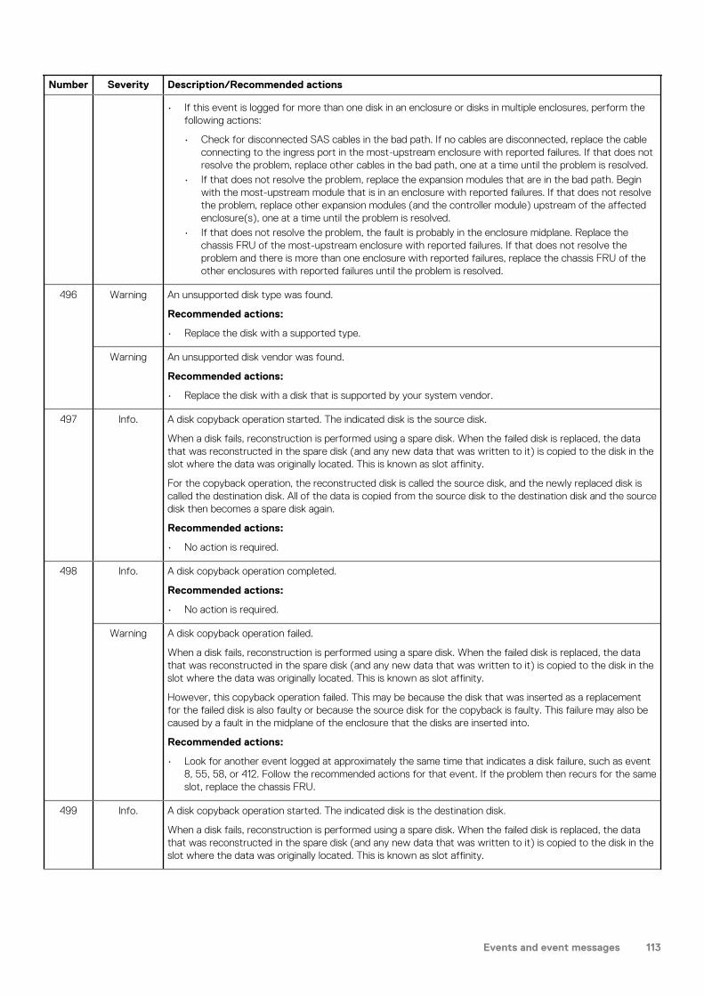
Number Severity Description/Recommended actions
• If this event is logged for more than one disk in an enclosure or disks in multiple enclosures, perform the following actions:
• Check for disconnected SAS cables in the bad path. If no cables are disconnected, replace the cable connecting to the ingress port in the most-upstream enclosure with reported failures. If that does not resolve the problem, replace other cables in the bad path, one at a time until the problem is resolved.
• If that does not resolve the problem, replace the expansion modules that are in the bad path. Begin with the most-upstream module that is in an enclosure with reported failures. If that does not resolve the problem, replace other expansion modules (and the controller module) upstream of the affected enclosure(s), one at a time until the problem is resolved.
• If that does not resolve the problem, the fault is probably in the enclosure midplane. Replace the chassis FRU of the most-upstream enclosure with reported failures. If that does not resolve the problem and there is more than one enclosure with reported failures, replace the chassis FRU of the other enclosures with reported failures until the problem is resolved.
496 Warning An unsupported disk type was found.
Recommended actions:
• Replace the disk with a supported type.
Warning An unsupported disk vendor was found.
Recommended actions:
• Replace the disk with a disk that is supported by your system vendor.
497 Info. A disk copyback operation started. The indicated disk is the source disk.
When a disk fails, reconstruction is performed using a spare disk. When the failed disk is replaced, the data that was reconstructed in the spare disk (and any new data that was written to it) is copied to the disk in the slot where the data was originally located. This is known as slot affinity.
For the copyback operation, the reconstructed disk is called the source disk, and the newly replaced disk is called the destination disk. All of the data is copied from the source disk to the destination disk and the source disk then becomes a spare disk again.
Recommended actions:
• No action is required.
498 Info. A disk copyback operation completed.
Recommended actions:
• No action is required.
Warning A disk copyback operation failed.
When a disk fails, reconstruction is performed using a spare disk. When the failed disk is replaced, the data that was reconstructed in the spare disk (and any new data that was written to it) is copied to the disk in the slot where the data was originally located. This is known as slot affinity.
However, this copyback operation failed. This may be because the disk that was inserted as a replacement for the failed disk is also faulty or because the source disk for the copyback is faulty. This failure may also be caused by a fault in the midplane of the enclosure that the disks are inserted into.
Recommended actions:
• Look for another event logged at approximately the same time that indicates a disk failure, such as event 8, 55, 58, or 412. Follow the recommended actions for that event. If the problem then recurs for the same slot, replace the chassis FRU.
499 Info. A disk copyback operation started. The indicated disk is the destination disk.
When a disk fails, reconstruction is performed using a spare disk. When the failed disk is replaced, the data that was reconstructed in the spare disk (and any new data that was written to it) is copied to the disk in the slot where the data was originally located. This is known as slot affinity.
Events and event messages 113

Number Severity Description/Recommended actions
For the copyback operation, the reconstructed disk is called the source disk, and the newly replaced disk is called the destination disk. All of the data is copied from the source disk to the destination disk and the source disk then becomes a spare disk again.
Recommended actions:
• No action is required.
500 Info. A disk copyback operation completed. The indicated disk was restored to being a spare.
When a disk fails, reconstruction is performed using a spare disk. When the failed disk is replaced, the data that was reconstructed in the spare disk (and any new data that was written to it) is copied to the disk in the slot where the data was originally located. This is known as slot affinity.
For the copyback operation, the reconstructed disk is called the source disk, and the newly replaced disk is called the destination disk. All of the data is copied from the source disk to the destination disk and the source disk then becomes a spare disk again.
Recommended actions:
• No action is required.
501 Error The enclosure hardware is not compatible with the I/O module firmware.
The Expander Controller firmware detected an incompatibility with the midplane type. As a preventive measure, disk access was disabled in the enclosure.
Recommended actions:
• If using a supported enclosure, update the storage system to the latest firmware. If using an unsupported enclosure, replace the unsupported enclosure with a supported one.
502 Warning The indicated SSD has 5% or less of its life remaining.
This event will be logged again as the device approaches and reaches its end of life.
Recommended actions:
• Be sure you have a spare SSD of the same type and capacity available.• If a spare is available, replace the SSD now.
Info. The indicated SSD has 20% or less of its life remaining.
This event will be logged again with a severity of Warning as the SSD further approaches its end of life.
Recommended actions:
• Obtain a replacement SSD of the same type and capacity if you do not already have one available.
503 Info. The Intelligent BackEnd Error Monitor (IBEEM) has discovered that continuous errors are being reported for the indicated PHY.
IBEEM logged this event after monitoring the PHY for 30 minutes.
Recommended actions:
504 Info. Service debug access to the system has been enabled or disabled
• No action is required.
by a user. Allowing service debug access may have security implications. After the diagnosis is complete you may want to disallow such access.
Recommended actions:
• No action is required.
505 Warning The indicated virtual pool was created with a size smaller than 500 GB, which can lead to unpredictable behavior.
The storage system may not perform correctly.
Recommended actions:
• Add disk groups to the virtual pool to increase the size of the pool.
114 Events and event messages

Number Severity Description/Recommended actions
506 Info. Addition of the indicated disk group was started.
When this operation is complete, event 467 is logged.
Recommended actions:
• No action is required.
507 Info. The link speed of the indicated disk does not match the link speed that the enclosure is capable of.
This event is logged when the auto-negotiated link speed is less than the maximum speed that the enclosure supports. The disk is functional, but I/O performance is reduced. This event may be logged for one disk channel or for both disk channels.
Recommended actions:
• If the disk is a member of a non-fault-tolerant disk group (RAID 0 or non-RAID), move the data to a different disk group.
• Replace the disk with one of the same type (SSD, enterprise SAS, or midline SAS) and the same or greater capacity. For continued optimum I/O performance, the replacement disk should have performance that is the same as or better than the one it is replacing.
508 Error The indicated virtual pool went offline. All of its volumes also went offline.
All data in the virtual pool has been lost. This condition can be caused by corrupt or inaccessible virtual pool metadata.
Recommended actions:
• Check for other events that indicate faults in the system and follow the recommended actions for those events.
• Re-create the virtual pool.• Restore the data from a backup, if available.
509 Error The metadata volume for the indicated virtual pool went offline. Volume mappings and persistent reservations are inaccessible or lost.
Recommended actions:
• Check for other events that indicate faults in the system and follow the recommended actions for those events.
• Create new mappings for the volumes. Persistent reservations will be restored by host systems automatically.
510 Info. The FDE lock key has been set or changed by a user.
Recommended actions:
• Be sure to record the lock key passphrase and the new lock ID.
511 Info. The FDE import lock key has been set by a user.
This is normally used to import into the system an FDE disk that was locked by another system.
Recommended actions:
• Ensure that the imported disks are integrated into the system.
512 Info. The system was set to the FDE secured state by a user.
Full Disk Encryption is now enabled. Disks removed from this system will not be readable unless they are imported into another system.
Recommended actions:
• No action is required.
513 Info. The system was set to the FDE repurposed state by a user.
All disks have been repurposed and set to their initial factory states. FDE is no longer enabled on the system.
Recommended actions:
• No action is required.
Events and event messages 115

Number Severity Description/Recommended actions
514 Info. The FDE lock key and import key were cleared by a user.
I/O operations may continue as long as the system is not restarted.
Recommended actions:
• If the system is restarted and access to data is intended, the lock key must be reinstated.
515 Info. An FDE disk was repurposed by a user.
The disk was reset to its original factory state.
Recommended actions:
• No action is required.
516 Error An FDE disk has been placed in the unavailable state.
The related event message 518, which indicates that a disk operation failed, may provide additional information.
Recommended actions:
• See the recommended action specified in the event message.
517 Info. A disk that was formerly in the FDE unavailable state is no longer unavailable.
The disk has returned to normal operations.
Recommended actions:
• No action is required.
518 Error An FDE disk operation has failed.
This event provides detail about the operation that failed.
Recommended actions:
• The disk may need to be removed, imported, repurposed, or replaced.
519 Error The system changed to the Full Disk Encryption degraded state.
Typically a disk-related condition has occurred.
Recommended actions:
• One or more disks may need to be removed, imported, repurposed, or replaced.
520 Info. The system that was in the Full Disk Encryption degraded state is no longer degraded.
The system has returned to normal operations.
Recommended actions:
• No action is required.
521 Error An error occurred while accessing the midplane SEEPROM to store or fetch Full Disk Encryption keys.
The midplane memory is used to store the FDE lock key.
Recommended actions:
• The midplane may need to be replaced if the error persists.
522 Warning A scrub-disk-group job encountered an error at the indicated logical block address.
The event message always includes the disk group name and the logical block address of the error within that disk group. If the block with an error falls within the LBA range used by a volume, the event message also includes the volume name and the LBA within that volume.
Recommended actions:
• Examine event 207 that was logged previously to this event. Follow the recommended actions for that event.
116 Events and event messages

Number Severity Description/Recommended actions
523 Info. This event provides additional details associated with a scrub-disk-group job, expanding on the information in event 206, 207, or 522.
Recommended actions:
• Follow the recommended actions for the associated event.
524 Error A temperature or voltage sensor reached a critical threshold.
A sensor monitored a temperature or voltage in the critical range. When the problem is resolved, event 47 is logged for the component that logged event 524.
If the event refers to a disk sensor, disk behavior may be unpredictable in this temperature range.
Check the event log to determine if more than one disk has reported this event.
• If multiple disks report this condition there could be a problem in the environment.• If one disk reports this condition, there could be a problem in the environment or the disk has failed.
Recommended actions:
• Check that the storage system’s fans are running.• Check that the ambient temperature is not too warm. The controller enclosure operating range is 5°C to
35°C (41°F to 95°F). The expansion enclosure operating range is 5°C to 40°C (41°F to 104°F).• Check for any obstructions to the airflow.• Check that there is a module or blank plate in every module slot in the enclosure.• If none of these recommended actions resolve the issue, replace the disk or controller module that logged
the error.
525 Info. A drawer has been stopped by a user.
The drawer has powered down and may be safely removed. A rescan must complete before the updated drawer information will be available.
Recommended actions:
• Restart the drawer using the start drawer command, or remove the drawer for replacement.
526 Info. A drawer has been started by a user.
The drawer has powered up. Disks in the drawer may take a few minutes to spin up. A rescan must complete before the updated drawer information will be available.
Recommended actions:
• No action is required.
527 Error Expander Controller (EC) firmware is incompatible with the enclosure.
As a preventative measure, the Expander Controller (EC) disabled all PHYs and reported the short enclosure status page in the supported diagnostic list.
Recommended actions:
• Upgrade the controller module to the latest supported bundle version.
528 Error Expander Controller firmware detected that the partner Expander Controller (EC) firmware is incompatible with the enclosure.
As a preventative measure, the Expander Controller (EC) disabled all PHYs and reported the short enclosure status page in the supported diagnostic list.
Recommended actions:
• Upgrade the partner controller module to the latest supported bundle version.
529 Error The local Expander Controller (EC) is incompatible with the enclosure.
As a preventative measure, the Expander Controller (EC) disabled all PHYs and reported the short enclosure status page in the supported diagnostic list.
Recommended actions:
• Replace the controller module with one that is compatible with the enclosure.
Events and event messages 117

Number Severity Description/Recommended actions
530 Error The local Expander Controller (EC) firmware detected a level of incompatibility with the partner Expander Controller (EC). This incompatibility could be due to unsupported hardware or firmware.
As a preventative measure, the local Expander Controller (EC) is holding the partner Expander Controller (EC) in a reset loop.
Recommended actions:
• Remove the partner controller module from the enclosure. Boot the partner controller module in single-controller mode in a separate enclosure (without the controller module that reported this event). Load the latest compatible bundle version. If the version fails to load, replace the partner controller module.
531 Error The indicated controller module was unable to recover from a stall. The system will need to be manually recovered.
Recommended actions:
• Download the debug logs from your storage system and contact technical support. A service technician can use the debug logs to determine the problem.
Warning The indicated controller module detected a stall. The system will perform corrective actions.
Recommended actions:
• No action is required.
532 Warning The partner controller module was killed due to encountering a protection information error during a write operation to disk.
If retries are successful after failover, the controller is deemed at fault. Otherwise, the disk is the likely cause of failure.
Recommended actions:
• Replace the killed controller if retry is successful after failover. Otherwise (if disk errors are encountered), replace the disk and bring the controller back into operation.
533 Error This event provides details about the result of the MC test of the indicated component.
If the test succeeded, the message says the component is present and operational. If the test failed, the message says the component is unavailable.
Recommended actions:
• If the event indicates the test failed, replace the controller module that logged this event.
Info. This event provides details about the result of the MC test of the indicated component.
Recommended actions:
• No action is required.
534 Info. The system determined that the indicated disk is degraded because it experienced a number of disk errors in excess of a configured threshold.
The indicated disk experienced a number of disk errors in excess of a configured threshold. Because the disk is part of a non-fault tolerant disk group, the system has set the disk status to degraded instead of failed.
Recommended actions:
• Monitor the disk.
Warning The system determined that the indicated disk is degraded because it experienced a number of disk errors in excess of a configured threshold.
The indicated disk experienced a number of disk errors in excess of a configured threshold. Because the disk is part of a non-fault tolerant disk group, the system has set the disk status to degraded instead of failed.
Recommended actions:
• Monitor the disk.
535 Warning A disk was placed into a FAILED state after the controller detected a protection information error.
118 Events and event messages

Number Severity Description/Recommended actions
Recommended actions:
• Replace the failed disk and return the other controller to operation.
536 Info. A disk protection information error was detected by the controller, but retries were successful. No further recovery action was necessary.
Recommended actions:
• No action is required.
537 Warning A disk was placed into a FAILED state after the disk reported a protection information error.
Recommended actions:
• Replace the failed disk.
538 Info. A protection information error was reported by the disk, but retries were successful. No further recovery action was necessary.
Recommended actions:
• No action is required.
539 Info. For the indicated disk group, which was corrupted, the 'recreate' step of the group recovery was not successful or the 'recreate' step of the disk group recovery succeeded.
Recommended actions:
• Verify that expected volumes have been recovered.• If the expected volumes were not recovered, the "recover volume" command may be used.• After verifying volume recovery, complete disk group recovery by running the 'recover disk-group
complete' command.
540 Info. The indicated volume, which was corrupted, has been recovered.
Recommended actions:
• After verifying volume recovery, complete disk group recovery by running the 'recover disk-group complete' command.
541 Info. For the indicated disk group, which was corrupted, the 'complete' step of the disk group recovery succeeded.
Recommended actions:
• No action is required.
542 Critical A data block was fenced by the controller due to lost data.
Event 543 will also be logged to describe volume information for the fenced data block.
Recommended actions:
• Perform recovery procedures, which may include restoring from backups.
543 Critical A data block in a volume was fenced by the controller due to lost data.
This event describes volume information for a fenced data block. It is logged in conjunction with event 542, which describes disk group and disk information for the data block.
Recommended actions:
• Perform recovery procedures, which may include restoring from backups.
544 Info. A disk group scrub operation exceeded its duration goal by 20%.
The system will attempt to meet the scrub duration goals by adjusting system resources, but factors such as the amount of data or abnormally high host activity may cause scrub operations to exceed the requested duration.
Recommended actions:
• If this event occurs repeatedly, the scrub duration goal should be increased to increase the likelihood that the goal can be met.
Events and event messages 119

Number Severity Description/Recommended actions
545 Warning A controller module is connected to a legacy enclosure midplane, resulting in degraded performance.
Recommended actions:
• To achieve better performance, replace the enclosure’s legacy chassis FRU with the latest version of the FRU.
546 Error The controller that logged this event killed the partner controller which has an incompatible host port configuration.
Recommended actions:
• Replace the killed controller module with a controller module that has the same host port configuration as the surviving controller module.
547 Warning The system determined that the indicated disk is degraded because it experienced a number of disk errors in excess of a configured threshold. The system has failed the disk, as specified by the configured policy.
Recommended actions:
• Replace the failed disk.
548 Warning Disk group reconstruction failed.
When a disk fails, reconstruction is performed using a spare disk. In this case, the reconstruction operation failed because unreadable data (uncorrectable media error) exists in at least one other disk in the disk group. Because of this, a portion of the data cannot be reconstructed.
Recommended actions:
• If you do not have a backup copy of the data in the disk group, make a backup.• Note the configuration of the disk group, such as its size and host mappings.• Look for another event logged at approximately the same time that indicates a disk failure, such as event
8, 55, 58, or 412. Follow the recommended actions for that event.• Remove the disk group.• Re-add the disk group.• Restore the data from the backup to a new disk group.
549 Critical The indicated controller module detected that it recovered from an internal processor fault.
Recommended actions:
• Replace the controller module.
Events (continued)Number Severity Description/Recommended actions
550 Critical The read data path between the Storage Controller and the disk drives was detected to be unreliable. The Storage Controller took action to correct this.
Recommended actions:
• Replace the controller.
551 Error An EMP reported one of the following for a power supply unit (PSU):
• The PSU is unable to communicate with the EMP.• The PSU in an enclosure does not have power supplied to it or has a hardware failure.• The PSU is running with corrupted firmware.
Recommended actions:
• If the EMP is unable to communicate with the indicated PSU:
• Wait for at least 10 minutes and check if the error resolves.• If the error persists, check that all modules in the enclosure are fully seated in their slots and that their
latches, if any, are locked.
120 Events and event messages

Number Severity Description/Recommended actions
• If this does not resolve the issue, note down the PSU. Ensure the partner PSU is not degraded. If the partner PSU is degraded, contact technical support.
• If the partner PSU is not degraded, remove and reinsert the indicated PSU..• If this does not resolve the issue, the indicated FRU has probably failed and should be replaced.
• If one of the PSUs in an enclosure does not have power supplied to it or has a hardware failure:
• Check that the indicated PSU is fully seated in its slot and that the PSU's latches, if any, are locked.• Check that each PSU has its switch turned on (if equipped with a switch).• Check that each power cable is firmly plugged into both the PSU and a functional electrical outlet.• If none of these recommended actions resolve the issue, the indicated PSU has probably failed and
should be replaced.• If a PSU is running with corrupted firmware:
• The indicated PSU has failed and should be replaced.
When the problem is resolved, an event with the same code will be logged with Resolved severity.
Warning An EMP reported that a power supply unit (PSU) has been uninstalled.
Recommended actions:
• Check that the indicated PSU is in the indicated enclosure.• If the PSU is not in the enclosure, install a PSU immediately.• If the PSU is in the enclosure, ensure that the power supply is fully seated in its slot and that its latch is
locked.• If none of these recommended actions resolves the issue, the indicated FRU has failed and should be
replaced.
When the problem is resolved, an event with the same code will be logged with Resolved severity.
Resolved A SES alert for a power supply in the indicated enclosure has been resolved.
Recommended actions:
• No action is required.
552 Error An EMP reported an alert condition.
• A hardware failure has been detected and all fans in the indicated FRU have failed.• The fan is unable to communicate with the EMP.
Recommended actions:
• If a hardware failure has been detected and all fans in the indicated FRU have failed.
• Inspect the system health information to determine which FRU contains the affected fans. Event 551 or 558 should give further information on the containing FRUs.
• Replace the containing FRUs.• If the fan is unable to communicate with the EMP.
• Wait for at least 10 minutes and check if the error resolves.• If the error persists, check that all modules in the enclosure are fully seated in their slots and that their
latches, if any, are locked.• If this does not resolve the issue, note down the FRU. Ensure the partner FRU is not degraded. If the
partner FRU is degraded, contact technical support.• If the partner FRU is not degraded, remove and reinsert the indicated FRU.• If these recommended actions do not resolve the issue, the indicated FRU has probably failed and
should be replaced
When the problem is resolved, an event with the same code will be logged with Resolved severity.
Warning An EMP reported one of the following:
• A fan in the indicated FRU has been uninstalled.• A fan in the indicated FRU has failed and fan redundancy for the FRU has been lost.
Recommended actions:
• If a fan in the indicated FRU has been uninstalled:
Events and event messages 121
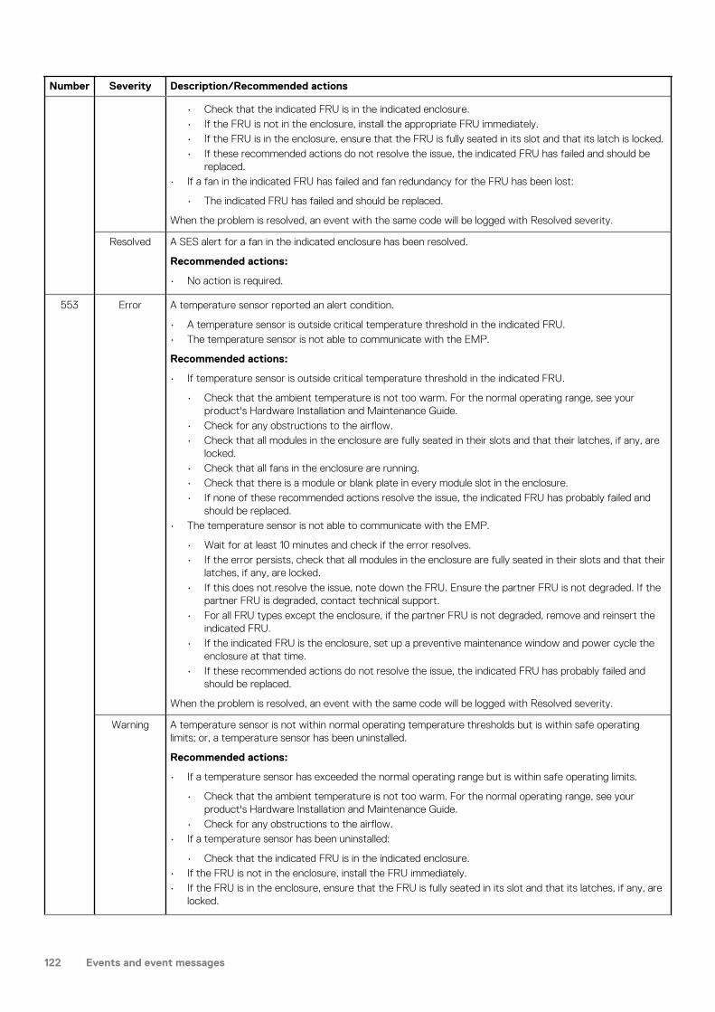
Number Severity Description/Recommended actions
• Check that the indicated FRU is in the indicated enclosure.• If the FRU is not in the enclosure, install the appropriate FRU immediately.• If the FRU is in the enclosure, ensure that the FRU is fully seated in its slot and that its latch is locked.• If these recommended actions do not resolve the issue, the indicated FRU has failed and should be
replaced.• If a fan in the indicated FRU has failed and fan redundancy for the FRU has been lost:
• The indicated FRU has failed and should be replaced.
When the problem is resolved, an event with the same code will be logged with Resolved severity.
Resolved A SES alert for a fan in the indicated enclosure has been resolved.
Recommended actions:
• No action is required.
553 Error A temperature sensor reported an alert condition.
• A temperature sensor is outside critical temperature threshold in the indicated FRU.• The temperature sensor is not able to communicate with the EMP.
Recommended actions:
• If temperature sensor is outside critical temperature threshold in the indicated FRU.
• Check that the ambient temperature is not too warm. For the normal operating range, see your product's Hardware Installation and Maintenance Guide.
• Check for any obstructions to the airflow.• Check that all modules in the enclosure are fully seated in their slots and that their latches, if any, are
locked.• Check that all fans in the enclosure are running.• Check that there is a module or blank plate in every module slot in the enclosure.• If none of these recommended actions resolve the issue, the indicated FRU has probably failed and
should be replaced.• The temperature sensor is not able to communicate with the EMP.
• Wait for at least 10 minutes and check if the error resolves.• If the error persists, check that all modules in the enclosure are fully seated in their slots and that their
latches, if any, are locked.• If this does not resolve the issue, note down the FRU. Ensure the partner FRU is not degraded. If the
partner FRU is degraded, contact technical support.• For all FRU types except the enclosure, if the partner FRU is not degraded, remove and reinsert the
indicated FRU.• If the indicated FRU is the enclosure, set up a preventive maintenance window and power cycle the
enclosure at that time.• If these recommended actions do not resolve the issue, the indicated FRU has probably failed and
should be replaced.
When the problem is resolved, an event with the same code will be logged with Resolved severity.
Warning A temperature sensor is not within normal operating temperature thresholds but is within safe operating limits; or, a temperature sensor has been uninstalled.
Recommended actions:
• If a temperature sensor has exceeded the normal operating range but is within safe operating limits.
• Check that the ambient temperature is not too warm. For the normal operating range, see your product's Hardware Installation and Maintenance Guide.
• Check for any obstructions to the airflow.• If a temperature sensor has been uninstalled:
• Check that the indicated FRU is in the indicated enclosure.• If the FRU is not in the enclosure, install the FRU immediately.• If the FRU is in the enclosure, ensure that the FRU is fully seated in its slot and that its latches, if any, are
locked.
122 Events and event messages

Number Severity Description/Recommended actions
When the problem is resolved, an event with the same code will be logged with Resolved severity.
Resolved A SES alert for a temperature sensor in the indicated enclosure has been resolved.
Recommended actions:
• No action is required.
554 Error A voltage sensor reported an alert condition.
• A voltage sensor is outside a critical voltage threshold in the indicated FRU.• A voltage sensor is not able to communicate with the EMP.
Recommended actions:
• If a voltage sensor is outside a critical voltage threshold in the indicated FRU:
• Check that all modules in the enclosure are fully seated in their slots and that their latches, if any, are locked.
• If this does not resolve the issue, the indicated FRU has probably failed and should be replaced.• If the voltage sensor is not able to communicate with the EMP:
• Wait for at least 10 minutes and check if the error resolves.• If the error persists, check that all modules in the enclosure are fully seated in their slots and that their
latches, if any, are locked.• If this does not resolve the issue, ensure the partner FRU is not degraded. If the partner FRU is
degraded, contact technical support.• For all FRU types except the enclosure, if the partner FRU is not degraded, remove and reinsert the
indicated FRU.• If the indicated FRU is the enclosure, set up a preventive maintenance window and power cycle the
enclosure at that time.• If these recommended actions do not resolve the issue, the indicated FRU has probably failed and
should be replaced.
When the problem is resolved, an event with the same code will be logged with Resolved severity.
Warning A voltage sensor is not within the normal operating range but is within safe operating limits; or, a voltage sensor has been removed.
Recommended actions:
• If a voltage sensor has exceeded the normal operating range but is within safe operating limits:
• Check that all modules in the enclosure are fully seated in their slots and that their latches are locked.• If this does not resolve the issue, the indicated FRU has probably failed and should be replaced.
• If a voltage sensor has been removed:
• Check that the indicated FRU is in the indicated enclosure.• If the FRU is not in the enclosure, install the FRU immediately.• If the FRU is in the enclosure, ensure that the FRU is fully seated in its slot and that its latches are
locked.• If these recommended actions do not resolve the issue, the indicated FRU has probably failed and
should be replaced.
When the problem is resolved, an event with the same code will be logged with Resolved severity.
Resolved A SES alert for a voltage sensor in the indicated enclosure has been resolved.
Recommended actions:
• No action is required.
555 Error The local Expander Controller firmware has detected a level of incompatibility with the partner Expander Controller firmware or hardware. As a preventive measure, the local Expander Controller may disable all the PHYs.
Recommended actions:
• Check that both the Expander Controllers have the correct firmware revision.
Events and event messages 123

Number Severity Description/Recommended actions
• If both Expander Controllers have different firmware versions, upgrade the partner controller module to the appropriate firmware that is compatible with the enclosure.
• If these recommended actions do not resolve the issue, replace the partner controller module.
When the problem is resolved, an event with the same code will be logged with Resolved severity.
Warning An expander in a controller module, expansion module, or drawer is mated but is not responding; or, an expander in an expansion module has been removed.
Recommended actions:
• Check that the indicated FRU is in the indicated enclosure.• If the FRU is not in the enclosure, install the appropriate FRU immediately.• If the FRU is in the enclosure, ensure that the FRU is fully seated in its slot and that its latches, if any, are
locked.• If these recommended actions do not resolve the issue, the indicated FRU has failed and should be
replaced.
When the problem is resolved, an event with the same code will be logged with Resolved severity,
Resolved A SES alert for an expander in the indicated enclosure has been resolved.
Recommended actions:
• No action is required.
556 Error An alert condition was detected on a root expander or drawer expander element.
Recommended actions:
• Replace the module that contains the indicated expander. This could be an IOM, sideplane or a drawer. Contact technical support for replacement of the module containing the drawer expander.
CAUTION: The sideplanes on the enclosure drawers are not hot swappable or customer serviceable.
• If these recommended actions do not resolve the issue, contact technical support. The enclosure must be replaced.
When the problem is resolved, an event with the same code will be logged with Resolved severity.
Warning An alert condition was detected on a root expander or drawer expander element.
Recommended actions:
• If uninstalled, the expander associated with the sideplane or drawer will have to be installed. Contact technical support. Otherwise, replace the module that contains the indicated expander. This could be a sideplane or a drawer. Contact technical support for replacement of the module containing the drawer expander.
CAUTION: The sideplanes on the enclosure drawers are not hot swappable or customer serviceable.
• If these recommended actions do not resolve the issue, contact technical support. The enclosure must be replaced.
When the problem is resolved, an event with the same code will be logged with Resolved severity.
Resolved A SES alert for an expander in the indicated enclosure has been resolved.
Recommended actions:
• No action is required.
557 Error An Enclosure Management Processor (EMP) reported an alert condition on a current sensor.
• The EMP is unable to communicate with the indicated current sensor.• The current sensor is outside critical threshold values.
Recommended actions:
• If the EMP is unable to communicate with the indicated current sensor:
• Wait for at least 10 minutes and check if the error resolves.
124 Events and event messages

Number Severity Description/Recommended actions
• If the error persists, check that all modules in the enclosure are fully seated in their slots and that their latches, if any, are locked.
• If this does not resolve the issue, ensure the partner FRU is not degraded. If the partner FRU is degraded, contact technical support.
• For all FRU types except the enclosure, if the partner FRU is not degraded, remove and reinsert the indicated FRU.
• If the indicated FRU is the enclosure, set up a preventive maintenance window and power cycle the enclosure at that time.
• If these recommended actions do not resolve the issue, the indicated FRU has probably failed and should be replaced.
• If the current sensor is outside critical threshold values:
• Check that all modules in the enclosure are fully seated in their slots and that their latches, if any, are locked.
• If these recommended actions do not resolve the issue, the indicated FRU has probably failed and should be replaced.
When the problem is resolved, an event with the same code will be logged with Resolved severity.
Warning An Enclosure Management Processor (EMP) reported an alert condition on a current sensor.
• A current sensor is outside the defined warning threshold values.• A current sensor has been uninstalled.
Recommended actions:
• If a current sensor has exceeded the defined warning threshold values:
• Check that all modules in the enclosure are fully seated in their slots and that their latches, if any are locked.
• If this does not resolve the issue, the indicated FRU has probably failed and should be replaced.• If a current sensor has been uninstalled:
• Check that the indicated FRU is in the indicated enclosure.• If the FRU is not in the enclosure, install the FRU immediately.• If the FRU is in the enclosure, ensure that the FRU is fully seated in its slot and that its latches, if any,
are locked.• If these recommended actions do not resolve the issue, the indicated FRU has probably failed and
should be replaced.
When the problem is resolved, an event with the same code will be logged with Resolved severity.
Resolved A SES alert for a current sensor in the indicated enclosure has been resolved.
Recommended actions:
• No action is required.
558 Error An Enclosure Management Processor (EMP) reported an alert condition on a fan control module.
A fan module in the enclosure has failed.
Recommended actions:
• Replace the fan module.
Warning An Enclosure Management Processor (EMP) reported an alert condition on a fan control module.
The hot swap circuit in the indicated fan module has failed. The fan will continue to operate. However, it is unsafe to remove this FRU while the enclosure is powered up.
Recommended actions:
• -Check that the indicated fan control module is in the indicated enclosure.• If the fan control module is not in the enclosure, install a fan control module FRU immediately.• If the fan control module is in the enclosure, ensure that the fan control module is fully seated in its slot
and that its latch is locked. If the fan control module is fully seated and the Fault/Service Required LEDs for the fan control module and for the enclosure are on, replace the fan control module FRU immediately. If that does not resolve the problem, replace the chassis FRU immediately.
Events and event messages 125
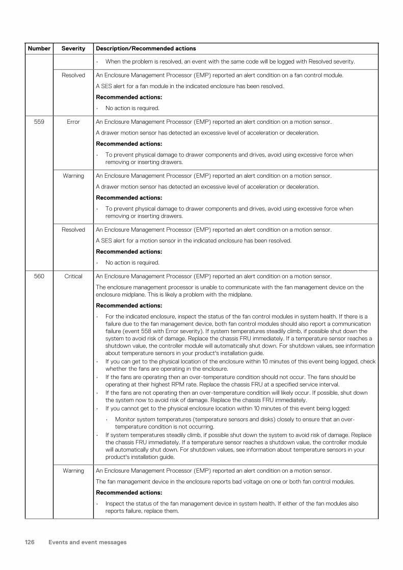
Number Severity Description/Recommended actions
• When the problem is resolved, an event with the same code will be logged with Resolved severity.
Resolved An Enclosure Management Processor (EMP) reported an alert condition on a fan control module.
A SES alert for a fan module in the indicated enclosure has been resolved.
Recommended actions:
• No action is required.
559 Error An Enclosure Management Processor (EMP) reported an alert condition on a motion sensor.
A drawer motion sensor has detected an excessive level of acceleration or deceleration.
Recommended actions:
• To prevent physical damage to drawer components and drives, avoid using excessive force when removing or inserting drawers.
Warning An Enclosure Management Processor (EMP) reported an alert condition on a motion sensor.
A drawer motion sensor has detected an excessive level of acceleration or deceleration.
Recommended actions:
• To prevent physical damage to drawer components and drives, avoid using excessive force when removing or inserting drawers.
Resolved An Enclosure Management Processor (EMP) reported an alert condition on a motion sensor.
A SES alert for a motion sensor in the indicated enclosure has been resolved.
Recommended actions:
• No action is required.
560 Critical An Enclosure Management Processor (EMP) reported an alert condition on a motion sensor.
The enclosure management processor is unable to communicate with the fan management device on the enclosure midplane. This is likely a problem with the midplane.
Recommended actions:
• For the indicated enclosure, inspect the status of the fan control modules in system health. If there is a failure due to the fan management device, both fan control modules should also report a communication failure (event 558 with Error severity). If system temperatures steadily climb, if possible shut down the system to avoid risk of damage. Replace the chassis FRU immediately. If a temperature sensor reaches a shutdown value, the controller module will automatically shut down. For shutdown values, see information about temperature sensors in your product's installation guide.
• If you can get to the physical location of the enclosure within 10 minutes of this event being logged, check whether the fans are operating in the enclosure.
• If the fans are operating then an over-temperature condition should not occur. The fans should be operating at their highest RPM rate. Replace the chassis FRU at a specified service interval.
• If the fans are not operating then an over-temperature condition will likely occur. If possible, shut down the system now to avoid risk of damage. Replace the chassis FRU immediately.
• If you cannot get to the physical enclosure location within 10 minutes of this event being logged:
• Monitor system temperatures (temperature sensors and disks) closely to ensure that an over-temperature condition is not occurring.
• If system temperatures steadily climb, if possible shut down the system to avoid risk of damage. Replace the chassis FRU immediately. If a temperature sensor reaches a shutdown value, the controller module will automatically shut down. For shutdown values, see information about temperature sensors in your product's installation guide.
Warning An Enclosure Management Processor (EMP) reported an alert condition on a motion sensor.
The fan management device in the enclosure reports bad voltage on one or both fan control modules.
Recommended actions:
• Inspect the status of the fan management device in system health. If either of the fan modules also reports failure, replace them.
126 Events and event messages

Number Severity Description/Recommended actions
Resolved An Enclosure Management Processor (EMP) reported an alert condition on a motion sensor.
A SES alert for a fan management device in the indicated enclosure has been resolved.
Recommended actions:
• No action is required.
561 Error An Enclosure Management Processor (EMP) reported an alert condition on the front panel ear LED.
The EMP is unable to communicate with the front panel ear LED.
Recommended actions:
• Replace the chassis-and-midplane FRU for the indicated enclosure.• When the problem is resolved, an event with the same code will be logged with Resolved severity.
Info. An Enclosure Management Processor (EMP) reported an alert condition on the front panel ear LED.
Recommended actions:
• No action is required.
Resolved An Enclosure Management Processor (EMP) reported an alert condition on the front panel ear LED.
A SES alert for a front panel ear LED in the indicated enclosure has been resolved.
Recommended actions:
• No action is required.
562 Info. Virtual pool statistics have been reset.
Recommended actions:
• No action is required.
563 Info. A disk has been restarted.
Recommended actions:
• No action is required.
564 Error An Enclosure Management Processor (EMP) reported an alert condition in a drawer of the enclosure.
The EMP reported an alert condition in a drawer of the enclosure:
• The drawer power is bad.• Both drawer slices are in reset or are not responding.
Recommended actions:
• Contact technical support.• When the problem is resolved, an event with the same code will be logged with Resolved severity.
Warning An Enclosure Management Processor (EMP) reported an alert condition in a drawer of the enclosure.
The EMP reported an alert condition in a drawer of the enclosure. One of the slices in the drawer is in reset or is not responding.
Recommended actions:
• Contact technical support.• When the problem is resolved, an event with the same code will be logged with Resolved severity.
Resolved An Enclosure Management Processor (EMP) reported an alert condition in a drawer of the enclosure.
A SES alert for a drawer in the indicated enclosure has been resolved.
Recommended actions:
• No action is required.
565 Warning One of the PCIe buses is running at less than optimal speed.
Events and event messages 127

Number Severity Description/Recommended actions
This event is the result of a hardware problem that has caused the controller to run slower than expected. The system works, but I/O performance is degraded.
Recommended actions:
• Restart the controller that logged the event. If the problem persists, replace the controller module.
566 Info. One of the DDR ports has been busy for at least 5 minutes.
This event is the result of a speed compensation while handling short data blocks. The system is operational but I/O performance is degraded.
Recommended actions:
• No action is required.
568 Info. A disk group has mixed physical sector size disks (for example 512n and 512e disks in the same disk group).
This event is the result of the user selecting disks with sector formats that do not match or a global spare replacement with a different sector format than the disk group. This could result in degraded performance for some workloads.
Recommended actions:
• No action is required.
569 Warning A SAS host cable mismatch has been detected for port. The indicated alternate PHYs have been disabled.
For example, a fan-out cable is connected to a controller module host port but the port is configured to use standard SAS cables, or vice versa.
Recommended actions:
• To use the connected cable, use the CLI 'set host-parameters' command to configure ports to use the proper cable type.
• Otherwise, replace the cable with the type of cable that the port is configured to use.• When the problem is resolved, an event with the same code will be logged with Resolved severity.
Resolved A previously detected SAS host cable mismatch has been resolved for port.
The proper cable type has been connected.
Recommended actions:
• No action is required.
571 Error Allocated snapshot space exceeded the configured percentage limit of the virtual pool.
If the snapshot space limit policy is set to delete snapshots, the system will begin to delete snapshots according to the snapshot retention priority setting until the snapshot space usage drops below the configured limit. Otherwise, the system will begin to use general pool space for snapshots until snapshots are manually deleted. If the storage usage drops below a threshold, event 572 is logged.
Recommended actions:
• If the snapshot space limit policy is set to notify only, you should immediately take steps to reduce snapshot space usage or add storage capacity.
• If the snapshot space policy is set to delete, the system will reduce snapshot space automatically, or log event 573 if no snapshots can be deleted.
Warning Allocated snapshot space exceeded the high snapshot space threshold.
The high threshold setting indicates that the pool is nearly out of snapshot space. The threshold settings are intended to indicate that the pool is using a significant portion of configured snapshot space and should be monitored. If the storage usage drops below any threshold, event 572 is logged.
Recommended actions:
• Reduce the snapshot space usage by deleting snapshots that are no longer needed.
Info. Allocated snapshot space exceeded either the low or middle snapshot space threshold.
128 Events and event messages
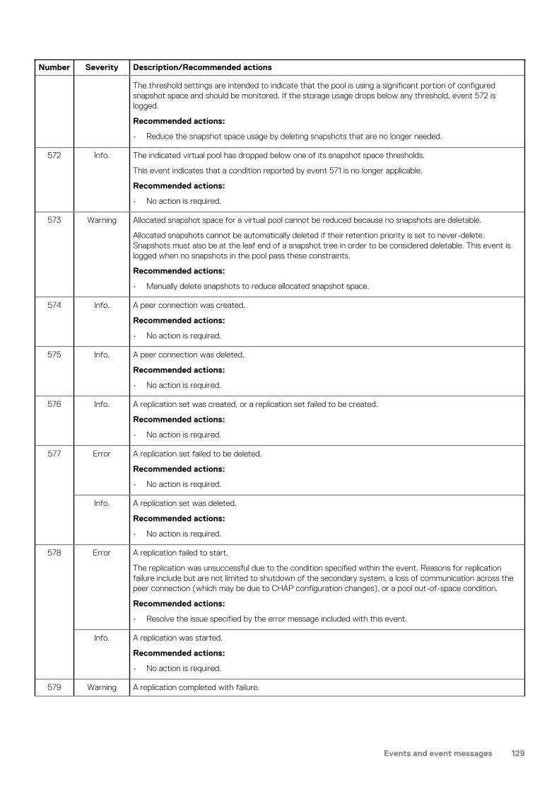
Number Severity Description/Recommended actions
The threshold settings are intended to indicate that the pool is using a significant portion of configured snapshot space and should be monitored. If the storage usage drops below any threshold, event 572 is logged.
Recommended actions:
• Reduce the snapshot space usage by deleting snapshots that are no longer needed.
572 Info. The indicated virtual pool has dropped below one of its snapshot space thresholds.
This event indicates that a condition reported by event 571 is no longer applicable.
Recommended actions:
• No action is required.
573 Warning Allocated snapshot space for a virtual pool cannot be reduced because no snapshots are deletable.
Allocated snapshots cannot be automatically deleted if their retention priority is set to never-delete. Snapshots must also be at the leaf end of a snapshot tree in order to be considered deletable. This event is logged when no snapshots in the pool pass these constraints.
Recommended actions:
• Manually delete snapshots to reduce allocated snapshot space.
574 Info. A peer connection was created.
Recommended actions:
• No action is required.
575 Info. A peer connection was deleted.
Recommended actions:
• No action is required.
576 Info. A replication set was created, or a replication set failed to be created.
Recommended actions:
• No action is required.
577 Error A replication set failed to be deleted.
Recommended actions:
• No action is required.
Info. A replication set was deleted.
Recommended actions:
• No action is required.
578 Error A replication failed to start.
The replication was unsuccessful due to the condition specified within the event. Reasons for replication failure include but are not limited to shutdown of the secondary system, a loss of communication across the peer connection (which may be due to CHAP configuration changes), or a pool out-of-space condition.
Recommended actions:
• Resolve the issue specified by the error message included with this event.
Info. A replication was started.
Recommended actions:
• No action is required.
579 Warning A replication completed with failure.
Events and event messages 129

Number Severity Description/Recommended actions
The replication was unsuccessful due to the condition specified within the event. Reasons for replication failure include but are not limited to shutdown of the secondary system, a loss of communication across the peer connection (which may be due to CHAP configuration changes), or a pool out of space condition.
Recommended actions:
• Resolve the issue specified by the error message included with this event.
Info. A replication completed successfully.
Recommended actions:
• No action is required.
580 Info. A replication was aborted.
Recommended actions:
• No action is required.
581 Warning A replication was suspended internally by the system.
The system will suspend the replication internally if it detects an error condition in the replication set and replications cannot continue for any reason. This includes but is not limited to shutdown of the secondary system, a loss of communication across the peer connection (which may be due to CHAP configuration changes), or a pool out-of-space condition.
Recommended actions:
• The replication will automatically resume once the condition described in this event is cleared.
Info. A replication was suspended by the user.
Recommended actions:
• No action is required.
582 Info. A replication has queued behind the active replication.
Recommended actions:
• No action is required.
583 Error The replication set was not reversed due to a failure.
During the Failback Restore operation, the replication direction for a replication set was not reversed due to a failure.
Recommended actions:
• If an issue with the peer connection was reported, check that appropriate interface cables are connected to the host ports defined in the peer connection.
• If the appropriate cables are connected, check the cables and any network switches for problems.• Otherwise, check the peer connection for invalid configuration.
Info. The replication direction for a replication set was reversed. Secondary is now primary. Primary is now secondary.
During the Failback Restore operation, the replication direction for a replication set was reversed.
Recommended actions:
• No action is required.
584 Info. A peer connection was modified.
Recommended actions:
• No action is required.
585 Info. A replication set was modified.
Recommended actions:
130 Events and event messages

Number Severity Description/Recommended actions
• No action is required.
586 Error Resuming the replication was unsuccessful due to the condition specified within the event. Reasons for replication failure include but are not limited to shutdown of the secondary system, a loss of communication across the peer connection (which may be due to CHAP configuration changes), or a pool out-of-space condition.
Recommended actions:
• Resolve the issue specified by the error message included with this event.
Info. A replication was resumed.
Recommended actions:
• No action is required.
587 Info. A pending replication was removed from the queue.
Recommended actions:
• No action is required.
588 Info. A replication set was failed over.
During the Failback Restore operation, a replication set was failed over
Recommended actions:
• No action is required.
589 Info. A replication set completed the Failback No Restore operation or failed to complete the Failback No Restore operation.
Recommended actions:
• No action is required.
590 Error A disk group has been quarantined.
This condition resulted from a controller flush/restore failure.
Recommended actions:
• To restore the disk group, use the CLI dequarantine command to dequarantine the disk group. If more than one disk group is quarantined you must individually dequarantine each disk group, whether it is fault tolerant or not. When dequarantine is complete, the disk group will return to the state it was in before being quarantined. For example, if the disk group was reconstructing before being quarantined, the disk group will resume reconstructing where it stopped
• For a linear disk group, if you want to find where parity is incorrect, use the CLI scrub vdisk command with the fix parameter disabled. This step is optional and not required to fix data integrity issues
• For a fault tolerant disk group, run either scrub disk-groups for a virtual disk group or scrub vdisk with the fix parameter enabled for a linear disk group. This step will make the parity consistent with the existing user data, and is required to fix data integrity issues.
• For a reconstructing disk group, let reconstruction finish, then run either scrub disk-groups for a virtual disk group or scrub vdisk with the fix parameter enabled for a linear disk group. This step will make the parity consistent with the existing user data, and is required to fix data integrity issues.
• Restore the data to the disk group from a backup copy.
591 Error A controller module has been fenced because of a failure or a controller module has been unfenced.
The indicated controller module is malfunctioning and has been isolated from the system. When the problem is resolved, an event with the same code will be logged with Informational severity.
Recommended actions:
• Replace the controller module that logged this event.
Resolved A controller module has been fenced because of a failure or a controller module has been unfenced.
Events and event messages 131

Number Severity Description/Recommended actions
A malfunction that caused the indicated controller module to be fenced has been resolved, and the controller module has been returned to service.
Recommended actions:
• No action is required.
593 Info. A PCIe bus has transitioned to a different speed.
Recommended actions:
• No action is required.
594 Info. The indicated disk in the indicated disk group is missing and the disk group is quarantined. While the disk group is quarantined, in linear storage any attempt to access its volumes from a host will fail. In virtual storage, all volumes in the pool will be forced read-only. If all of the disks become accessible, the disk group will be dequarantined automatically with a resulting status of FTOL. If not all of the disks become accessible but enough become accessible to allow reading from and writing to the disk group, it will be dequarantined automatically with a resulting status of FTDN or CRIT. If a spare disk is available, reconstruction will begin automatically. When the disk group has been removed from quarantine, event 173 is logged. For a more detailed discussion of dequarantine, see the PowerVault Manager or CLI documentation.
CAUTION:
• Avoid using the manual dequarantine operation as a recovery method when event 172 is logged because this causes data recovery to be more difficult or impossible.
• If you clear unwritten cache data while a disk group is quarantined or offline, that data will be permanently lost.
Recommended actions:
• If event 173 has subsequently been logged for the indicated disk group, no action is required. The disk group has already been removed from quarantine.
• Otherwise, perform the following actions:
• Check that all enclosures are powered on.• Check that all disks and I/O modules in every enclosure are fully seated in their slots and that their
latches are locked.• Reseat any disks in the quarantined disk group that are reported as missing or failed in the user
interface. (Do NOT remove and reinsert disks that are not members of the disk group that is quarantined.)
• Check that the SAS expansion cables are connected between each enclosure in the storage system and that they are fully seated. (Do NOT remove and reinsert the cables because this can cause problems with additional disk groups.)
• Check that no disks have been removed from the system unintentionally.• Check for other events that indicate faults in the system and follow the recommended actions for
those events. But, if the event indicates a failed disk and the recommended action is to replace the disk, do NOT replace the disk at this time because it may be needed later for data recovery.
• If the disk group is still quarantined after performing the preceding steps, shut down both controllers and then power down the entire storage system. Power it back up, beginning with any disk enclosures (expansion enclosures), then the controller enclosure.
• If the disk group is still quarantined after performing the preceding steps, contact technical support.
595 Info. This event reports the serial number of each controller module in this system.
Recommended actions:
• No action is required.
596 Warning Enclosure fault protection has been compromised for the indicated disk group.
To replace the failed disk, the system was unable to find a spare that met requirements to minimize the risk of data loss in the event of enclosure failure, so the system had to select a spare that did not meet the requirements. For a RAID-6 disk group, this means that more than two member disks are in the same enclosure. For other RAID levels, this means that more than one member disk is in the same enclosure.
Recommended actions:
132 Events and event messages

Number Severity Description/Recommended actions
• Replace the indicated failed disk in the indicated enclosure to restore enclosure fault protection.
597 Warning Drawer fault protection has been compromised for the indicated disk group.
To replace the failed disk, the system was unable to find a spare that met requirements to minimize the risk of data loss in the event of drawer failure, so the system had to select a spare that did not meet the requirements. For a RAID-6 disk group, this means that more than two member disks are in the same drawer. For other RAID levels, this means that more than one member disk is in the same drawer.
Recommended actions:
• Replace the indicated failed disk in the indicated enclosure to restore drawer fault protection.
598 Warning, Info.
Drive has failed a performance measurement.
Recommended actions:
• Monitor the disk.
599 Error The firmware has yet to retrieve Enclosure Power control status.
The Enclosure Power element provides enclosure level power control. This could occur shortly after a reboot or module insertion. It should only be treated as an error if it persists for more than 30 seconds after a reset.
Recommended actions:
• Contact technical support.• When the problem is resolved, an event with the same code will be logged with Resolved severity.
Warning, Resolved
The firmware has yet to retrieve Enclosure Power control status.
The Enclosure Power element provides enclosure level power control.
Recommended actions:
• No action is required.
602 Error, Warning
An alert condition was detected on a Midplane Interconnect element.
The Midplane Interconnect element reports status associated with the interface between the SBB I/O module and the midplane. This is typically some form of communication problem on the midplane interconnect.
Recommended actions:
• Contact technical support. Provide logs to technical support personnel for analysis.• When the problem is resolved, an event with the same code will be logged with Resolved severity.
Resolved A previous Warning or Error condition for the Midplane Interconnect element has been resolved.
The Midplane Interconnect element reports status associated with the interface between the SBB I/O module and the midplane.
Recommended actions:
• No action is required.
603 Error, Warning
An alert condition for a SAS Connector element has been detected.
The SAS Connector element report status information for both external and internal SAS port connectors.
Recommended actions:
• Contact technical support.• When the problem is resolved, an event with the same code will be logged with Resolved severity.
Info., Resolved
An alert condition for a SAS Connector element has been detected.
The SAS Connector element report status information for both external and internal SAS port connectors.
Recommended actions:
• No action is required.
Events and event messages 133

Number Severity Description/Recommended actions
604 Warning A replication snapshot was attempted and failed.
A replication-set has been configured to retain snapshots of the volume. An error is possible if the snapshot fails.
Recommended actions:
• Monitor the health of the local system, the replication-set, the volume, and the peer-connection. A full storage pool may be the cause of this fault.
• Check the peer-connection system health and state.• Ensure that the Maximum Licensable Snapshots limit (shown by the CLI show license command)
was not exceeded.
605 Warning Inactive processing core.
The controller module has multiple processing cores. The system has enough active cores to operate but performance is degraded.
Recommended actions:
• Attempt to restart all the processing cores as follows:
• Shut down the controller module that logged this event.• Remove the controller module, wait 30 seconds, and then reinsert the controller module.
• If this event is logged again, contact technical support.
606 Error A controller contains unwritten cache data for a volume, and its supercapacitor has failed to charge.
Due to the supercapacitor failure, if the controller loses power, it will not have backup power to flush the unwritten data from cache to CompactFlash.
Recommended actions:
• Verify that the cache-write policy is write-through for all volumes.• Contact technical support for information about replacing the controller module.
607 Warning The local controller is rebooting the other controller.
Recommended actions:
• No action is required.
608 Error A back-end cabling error was detected.
Recommended actions:
• If the message says both controllers are connected with a undefined error type, one of the cables is incorrectly connected to a controller egress port forming a loop in the SAS topology. Check back-end cabling from each controller egress port to determine the incorrect connection.
• If the message says controller egress ports are connected to each other, one of the cables is incorrectly connected to a controller egress port forming a loop in the SAS topology. Check back-end cabling and make sure that SAS cables are connected to the correct ports for the port specified.
• If the message says an EBOD loop has been created, one of the cables is incorrectly connected to an expansion enclosure egress port forming a loop in the SAS topology. Check back-end cabling and make sure that SAS cables are connected to the correct ports for the port specified.
• If the message says a cable is connected to the middle port but that port is not supported, check back-end cabling and make sure that SAS cables are connected to the correct ports for the port specified. Move the cable from the middle port of the IOM to the left or right port, as appropriate.
609 Error An alert condition was detected on a door lock element. The door lock element reports status associated with the enclosure drawer. The drawer has been reporting as open for a long period of time. This may reduce cooling, potentially causing the enclosure to overheat.
Recommended actions:
• Check that the drawer is fully closed and latched.
When the problem is resolved, an event with the same code will be logged with Resolved severity.
134 Events and event messages

Number Severity Description/Recommended actions
Info. An alert condition was detected on a door lock element. The door lock element reports status associated with the enclosure drawer. The drawer sensor is reporting uninstalled.
Recommended actions:
• No action is required.
Resolved A previous Informational or Error condition for the door lock element has been resolved.
Recommended actions:
• No action is required.
610 Error An alert condition was detected on a sideplane element.
Recommended actions:
• Check the drawer that the indicated sideplane is fully closed and latched.CAUTION: The sideplanes on the enclosure drawers are not hot swappable or customer serviceable.
• If this does not resolve the issue, contact technical support. The enclosure must be replaced.
Warning An alert condition was detected on a sideplane element.
Recommended actions:
• The sideplane associated with the drawer must be installed. Contact technical support.CAUTION: The sideplanes on the enclosure drawers are not hot swappable or customer serviceable.
Resolved A previous Warning or Error condition for the sideplane element has been resolved.
Recommended actions:
• No action is required.
611 Error Email notification failed due to either:
• An unreachable SMTP server or a difference between the sender and SMTP server domains.• Improper configuration.
Recommended actions:
• Verify the configured parameters and ask the recipients to confirm that they received the message.
Info. Email notification sent successfully. Please ask the recipients to confirm that they received the message.
Recommended actions:
• Verify the configured parameters and ask the recipients to confirm that they received the message.
612 Info. An alert condition was detected on an internal chassis SAS connector.
The event message specifies the location of the internal SAS connector in the chassis.
Recommended actions:
• No action is required.
613 Error An alert condition was detected on an IOM.
Recommended actions:
• Either install the indicated IOM or attempt to reseat it.• If the problem persists, replace the IOM.
Warning An alert condition was detected on an IOM.
Recommended actions:
• If uninstalled, install the indicated IOM otherwise attempt to reseat it.• If the problem persists, replace the IOM.
Info. An IOM was uninstalled.
Events and event messages 135

Number Severity Description/Recommended actions
Recommended actions:
• No action is required.
Resolved A previous Warning or Error condition for the IOM has been resolved.
Recommended actions:
• No action is required.
615 Info. A rebalance operation for an ADAPT disk group has started.
Recommended actions:
• No action is required.
616 Warning A rebalance operation for an ADAPT disk group has completed partially.
Recommended actions:
• No action is required.
Info. A rebalance operation for an ADAPT disk group has completed.
Recommended actions:
• No action is required.
617 Warning The spare capacity goal is not met.
This event indicates that the available space in the system is insufficient to provide the level of full fault tolerance that is specified by the target spare capacity. Spare capacity availability can be influenced by operations that require available space in the system, such as reconstructing data from a failed disk.
Recommended actions:
• Add disks to the disk group, or replace any disks that may have failed. The system will automatically increase the spare capacity to meet the requirements placed on the system by the target spare capacity.
618 Resolved The spare capacity goal is met.
Recommended actions:
• No action is required.
619 Info. The controller has been injected with a fault to introduce a broadcast receiver (BR) link error.
Recommended actions:
• No action is required.
620 Error Expander zoning is enabled, which may limit disk access.
Disk access will change depending on the port used to connect to the expander.
Recommended actions:
• Load a valid firmware bundle to disable zoning.
Resolved Expander zoning has been disabled for the indicated enclosure.
Recommended actions:
• No action is required.
621 Info. Degraded ADAPT rebalance operation started. This operation takes fault tolerant stripe zones and makes them degraded so critical stripe zones can be made degraded.
Recommended actions:
• No action is required.
622 Info. Degraded ADAPT rebalance operation completed. This operation takes fault tolerant stripe zones and makes them degraded so critical stripe zones can be made degraded.
Recommended actions:
136 Events and event messages

Number Severity Description/Recommended actions
• No action is required.
623 Info. Management Controller configuration parameters were set.
One or more configuration parameters associated with the Management Controller (MC) have been changed, such as configuration for SNMP, SMI-S (not supported on the ME4084), email notification, and system strings (system name, system location, etc.).
Recommended actions:
• No action is required.
624 Warning The Top Level Assembly data was changed.
Recommended actions:
• No action is required.
625 Warning The system brand was changed.
Recommended actions:
• No action is required.
626 Info. Detected an unsupported TPID (midplane Type ID).
Recommended actions:
• No action is required.
627 Info. Detected an unknown TPID (midplane Type ID).
Recommended actions:
• No action is required.
628 Error A firmware mismatch has been identified for the expansion enclosure.
A firmware mismatch could result from attaching an enclosure configured as a JBOD (instead of an EBOD) or installing a new IOM FRU with incompatible firmware.
Recommended actions:
• Update the firmware to the appropriate level for connecting your expansion enclosures to the controller enclosure.
• If you receive this event when no new enclosures or IOMs have been added, please contact support.
646 Info. Indicates any of the following changes to SupportAssist:
• State changed• Contact information changed• Proxy settings changed or cleared• Operation mode changed• Settings changed
Recommended actions:
• No action is required.
647 Error This Storage Controller is restarting due to an internal error.
This Storage Controller experienced a management-interface hang and will restart to recover.
Recommended actions:
• Please collect logs and contact technical support for further action.
648 Error Failed to upload SupportAssist logs or CloudIQ configuration or performance data.
Recommended actions:
• No action is required.
649 Warning A controller firmware update is available for your system.
Events and event messages 137

Number Severity Description/Recommended actions
Recommended actions:
• Go to https://www.dell.com/support, enter your service tag and download the update. You can then use the Update Firmware function in PowerVault Manager to perform the update.
650 Warning A disk firmware update is available for your system.
Recommended actions:
• Go to https://www.dell.com/support, enter your service tag and download the update. You can then use the Update Firmware function in PowerVault Manager to perform the update.
Removed eventsThe following table lists events that have been removed and specifies events that the system reports instead:
NOTE: If you have scripts that reference the removed events, update the scripts with the replacement events.
Table 27. Removed events
Removed event Replacement event
154 237
155 237
Events sent as indications to SMI-S clientsIf the storage system SMI-S interface is enabled, the system will send events as indications to SMI-S clients so that SMI-S clients can monitor system performance.
The following event categories pertain to FRU assemblies and certain FRU components:
FRU/Event category
Corresponding SMI-S class Operation status values that would trigger alert conditions
Controller DHS_Controller Down, Not Installed, OKHard Disk Drive DHS_DiskDrive Unknown, Missing, Error, Degraded, OKFan DHS_PSUFan Error, Stopped, OKPower Supply DHS_PSU Unknown, Error, Other, Stressed, Degraded, OKTemperature Sensor DHS_OverallTempSensor Unknown, Error, Other, Non-Recoverable Error,
Degraded, OKBattery/SuperCap DHS_SuperCap Unknown, Error, OKFC Port DHS_FCPort Stopped, OKSAS Port DHS_SASTargetPort Stopped, OKiSCSI Port DHS_ISCSIEthernetPort Stopped, OK
Using the trust commandUse the CLI trust command only as a last step in a disaster recovery situation.
Do not use the trust command if a disk group with a single disk is in a leftover or failed condition. The trust command may cause permanent data loss and unstable operation of the disk group. Only use the trust command if the disk group is in an Offline state.
A disk that has failed or is in a leftover state due to multiple errors should be replaced with a new disk. Assign the new disk back to the disk group as a spare. Then allow reconstruction to complete to return the disk group to a fault tolerant state.
138 Events and event messages

The trust command attempts to resynchronize leftover disks to make any leftover disk an active member of the disk group. The trust command may be needed when a disk group is offline because there is no data backup. The trust command may also be needed as a last attempt to recover the data on a disk group. In this case, the trust command may work, but only if the leftover disk continues to operate. When the "trusted" disk group is back online, backup all data on the disk group and verify all data to ensure it is valid. Then delete the trusted disk group, add a new disk group, and restore data from the backup to the new disk group.
NOTE: Using trust on a disk group is only a disaster-recovery measure. The disk group has no tolerance for another
failure and should never be put back into a production environment.
CAUTION: Before trusting a disk group, carefully read the cautions and procedures for using the trust command in the
Dell EMC PowerVault ME4 Series Storage System CLI Reference Guide and online help. If you are uncertain whether to
use this command, contact technical support for assistance.
Once the trust command has been issued on a disk group, further troubleshooting steps may be limited towards disaster recovery. If you are unsure of the correct action to take, contact technical support for further assistance.
Events and event messages 139
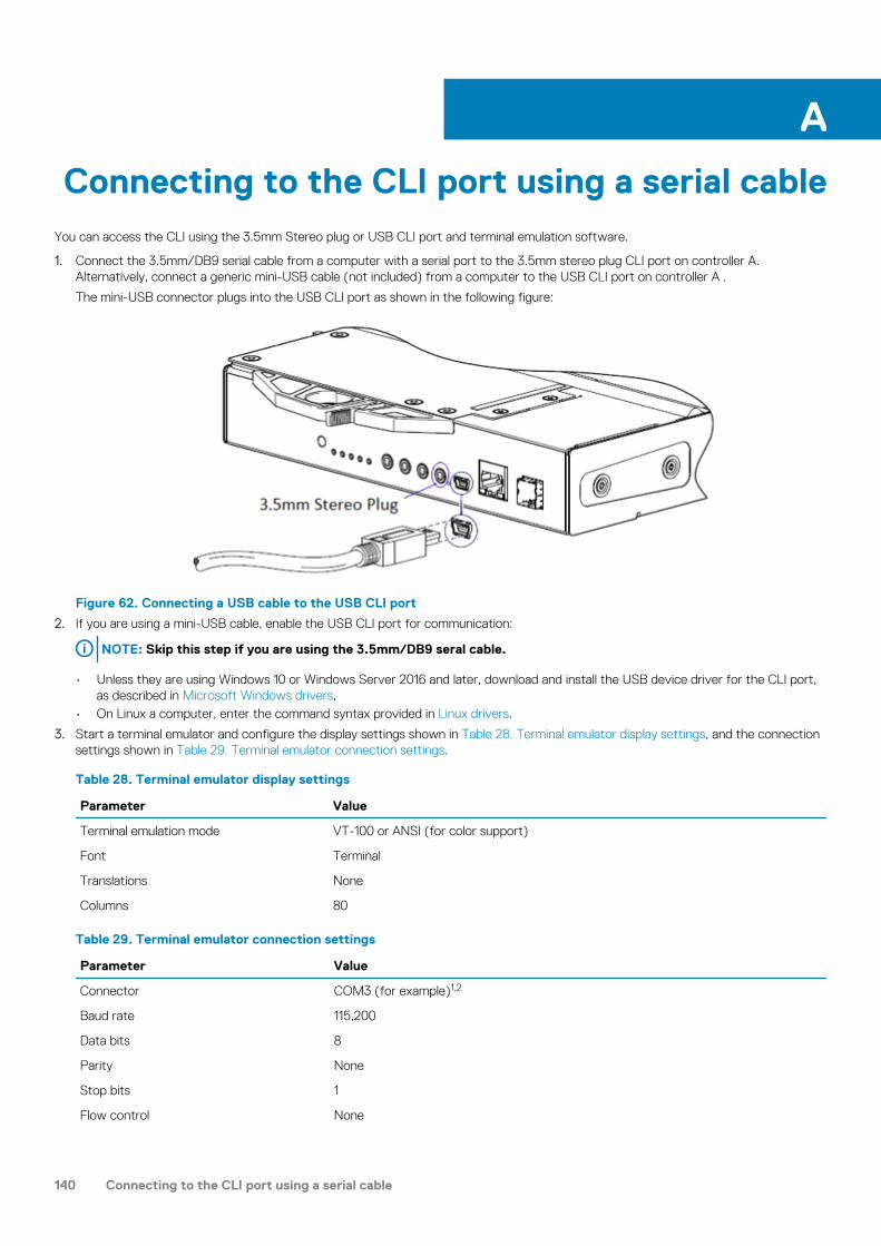
Connecting to the CLI port using a serial cableYou can access the CLI using the 3.5mm Stereo plug or USB CLI port and terminal emulation software.
1. Connect the 3.5mm/DB9 serial cable from a computer with a serial port to the 3.5mm stereo plug CLI port on controller A. Alternatively, connect a generic mini-USB cable (not included) from a computer to the USB CLI port on controller A .
The mini-USB connector plugs into the USB CLI port as shown in the following figure:
Figure 62. Connecting a USB cable to the USB CLI port
2. If you are using a mini-USB cable, enable the USB CLI port for communication:
NOTE: Skip this step if you are using the 3.5mm/DB9 seral cable.
• Unless they are using Windows 10 or Windows Server 2016 and later, download and install the USB device driver for the CLI port, as described in Microsoft Windows drivers,
• On Linux a computer, enter the command syntax provided in Linux drivers.
3. Start a terminal emulator and configure the display settings shown in Table 28. Terminal emulator display settings, and the connection settings shown in Table 29. Terminal emulator connection settings.
Table 28. Terminal emulator display settings
Parameter Value
Terminal emulation mode VT-100 or ANSI (for color support)
Font Terminal
Translations None
Columns 80
Table 29. Terminal emulator connection settings
Parameter Value
Connector COM3 (for example)1,2
Baud rate 115,200
Data bits 8
Parity None
Stop bits 1
Flow control None
A
140 Connecting to the CLI port using a serial cable

1 Your computer configuration determines which COM port is used for the Disk Array USB Port.
2 Verify the appropriate COM port for use with the CLI.
4. If necessary, press Enter to display login prompt.
a) Type the user name of a user with the manage role at the login prompt and press Enter.b) Type the password for the user at the Password prompt and press Enter.
Topics:
• Mini-USB Device Connection
Mini-USB Device ConnectionThe following sections describe the connection to the mini-USB port:
Emulated serial portWhen a computer is connected to a controller module using a mini-USB serial cable, the controller presents an emulated serial port to the computer. The name of the emulated serial port is displayed using a customer vendor ID and product ID. Serial port configuration is unnecessary.
NOTE: Certain operating systems require a device driver or special mode of operation to enable proper functioning of
the USB CLI port. See also Device driver/special operation mode.
Supported host applicationsThe following terminal emulator applications can be used to communicate with an ME4 Series controller module:
Table 30. Supported terminal emulator applications
Application Operating system
PuTTY Microsoft Windows (all versions)
Minicom Linux (all versions)
Command-line interfaceWhen the computer detects a connection to the emulated serial port, the controller awaits input of characters from the computer using the command-line interface. To see the CLI prompt, you must press Enter.
NOTE: Directly cabling to the mini-USB port is considered an out-of-band connection. The connection to the mini-USB
port is outside of the normal data paths to the controller enclosure.
Device driver/special operation modeCertain operating systems require a device driver or special mode of operation. The following table displays the product and vendor identification information that is required for certain operating systems:
USB identification code type Code
USB Vendor ID 0x210c
USB Product ID 0xa4a7
Connecting to the CLI port using a serial cable 141

Microsoft Windows driversDell EMC provides an ME4 Series USB driver for use in Windows environments.
Obtaining the USB driverNOTE: If you are using Windows 10 or Windows Server 2016, the operating system provides a native USB serial driver
that supports the mini-USB port. However, if you are using an older version of Windows, you should download and
install the USB driver.
1. Go to Dell.com/support and search for ME4 Series USB driver.
2. Download the ME4 Series Storage Array USB Utility file from the Dell EMC support site.
3. Follow the instructions on the download page to install the ME4 Series USB driver.
Known issues with the CLI port and mini-USB cable on Microsoft WindowsWhen using the CLI port and cable for setting network port IP addresses, be aware of the following known issue on Windows:
Problem
The computer might encounter issues that prevent the terminal emulator software from reconnecting after the controller module restarts or the USB cable is unplugged and reconnected.
Workaround
To restore a connection that stopped responding when the controller module was restarted:
1. If the connection to the mini-USB port stops responding , disconnect and quit the terminal emulator program.
a. Using Device Manager, locate the COMn port that is assigned to the mini-USB portb. Right-click on the Disk Array USB Port (COMn) port, and select Disable device.
2. Right-click on the Disk Array USB Port (COMn) port, and select Enable device.3. Start the terminal emulator software and connect to the COM port.
NOTE: On Windows 10 or Windows Server 2016, the XON/XOFF setting in the terminal emulator software must be
disabled to use the COM port.
Linux driversLinux operating systems do not require the installation of an ME4 Series USB driver. However, certain parameters must be provided during driver loading to enable recognition of the mini-USB port on an ME4 Series controller module.
• Type the following command to load the Linux device driver with the parameters that are required to recognize the mini-USB port:
# modprobe usbserial vendor=0x210c product=0xa4a7 use_acm=1
NOTE: Optionally, this information can be incorporated into the /etc/modules.conf file.
142 Connecting to the CLI port using a serial cable

Technical specifications
Enclosure dimensionsTable 31. 2U enclosure dimensions
Specification Metric units Imperial units
Overall enclosure height (2U) 87.9 mm 3.46 in
Width across mounting flange (located on front of chassis)
483 mm 19.01 in
Width across body of enclosure 443 mm 17.44 in
2U12 – Depth from face of mounting flange to back of enclosure body
576.8 mm 22.71 in
2U24 – Depth from face of mounting flange to back of enclosure body
526 mm 20.71 in
2U12 – Depth from face of mounting flange to rear most enclosure extremity
602.9 mm 23.74 in
2U24 – Depth from face of mounting flange to rear most enclosure extremity
552.2 mm 21.74 in
2U12 – Depth from face of Ops panel to rear most enclosure extremity
629.6 mm 24.79 in
2U24 – Depth from face of Ops panel to rear most enclosure extremity
578.9 mm 22.79 in
NOTE:
• The 2U24 enclosure uses 2.5" SFF disks.
• The 2U12 enclosure uses 3.5" LFF disks.
Table 32. 5U84 enclosure dimensions
Specification Metric units Imperial units
Overall enclosure height (2U) 222.3 mm 3.46 in
Width across mounting flange (located on front of chassis)
483 mm 19.01 in
Width across body of enclosure 443 mm 17.44 in
Depth from face of mounting flange to back of enclosure body
892.2 mm 35.12 in
Depth from face of mounting flange to rearmost enclosure extremity
974.7 mm 38.31 in
Depth from face of Ops panel to rearmost enclosure extremity
981 mm 38.62 in
NOTE: The 5U84 uses 3.5" LFF disks in the DDIC carrier. It can also use 2.5" SFF disks with 3.5" adapter in the DDIC.
B
Technical specifications 143

Enclosure weightsCRU/component 2U12 (kg/lb) 2U24 (kg/lb) 5U84 (kg/lb)
Storage enclosure (empty) 4.8/10.56 4.8/10.56 64/141
Disk drive carrier 0.9/1.98 0.3/0.66 0.8/1.8
Blank disk drive carrier (air management sled)
0.05/0.11 0.05/0.11 —
Power Cooling Module (PCM) 3.5/7.7 3.5/7.7 —
Power Supply Unit (PSU) — — 2.7/6
Fan Cooling Module (FCM) — — 1.4/3
SBB controller module (maximum weight) 2.6/5.8 2.6/5.8 2.6/5.8
SBB expansion module 1.5/3.3 1.5/3.3 1.5/3.3
RBOD enclosure (fully populated with modules: maximum weight)
32/71 30/66 135/298
EBOD enclosure (fully populated with modules: maximum weight)
28/62 25/55 130/287
NOTE:
• Weights shown are nominal, and subject to variances.
• 2U rail kits add between 2.8 kg (6.2 lb) and 3.4 kg (7.4 lb) to the aggregate enclosure weight. 5U84 rail kits add
significantly more weight.
• Weights may vary due to different controller modules, IOMs, and power supplies; and differing calibrations between
scales.
Weights may also vary due to the actual number and type of disk drives (SAS or SSD) and air management modules
installed.
Environmental requirementsTable 33. Ambient temperature and humidity
Specification Temperature range Relative humidity Max. Wet Bulb
Operating RBOD: 5ºC to 35ºC (41ºF to 95ºF)
EBOD: 5ºC to 40ºC (41ºF to 104ºF)
20% to 80% non-condensing
28ºC
Non-operating (shipping) -40ºC to +70ºC (-40ºF to +158ºF)
5% to 100% non-precipitating
29ºC
Specification Measurement/description
Airflow System must be operated with low pressure rear exhaust installation.
Back pressure created by rack doors and obstacles not to exceed 5Pa (0.5 mm H2O)
Altitude, operating 2U enclosures: 0 to 3,000 meters (0 to 10,000 feet)
Maximum operating temperature is de-rated by 5ºC above 2,133 meters (7,000 feet)
5U84 enclosures: -100 to 3,000 meters (-330 to 10,000 feet)
Maximum operating temperature is de-rated by 1ºC above 900 meters (3,000 feet)
144 Technical specifications

Specification Measurement/description
Altitude, non-operating -100 to 12,192 meters (-330 to 40,000 feet)
Shock, operating 5.0 g, 10 ms, ½ sine pulses, Y-axis
Shock, non-operating 2U enclosures: 30.0 g, 10 ms, ½ sine pulses
5U84 enclosures: 30.0 g, 10 ms, ½ sine pulses (Z-axis); 20.0 g, 10 ms, ½ sine pulses
(X- and Y-axes)
Vibration, operating 0.21 Grms 5 Hz to 500 Hz random
Vibration, non-operating 1.04 Grms 2 Hz to 200 Hz random
Vibration, relocation 0.3 Grms 2 Hz to 200 Hz 0.4 decades per minute
Acoustics Operating sound power
2U enclosures: ≤ LWAd 6.6 Bels (re 1 pW) @ 23ºC
5U84 enclosures: ≤ LWAd 8.0 Bels (re 1 pW) @ 23ºC
Orientation and mounting: 19" rack mount (2 EIA units; 5 EIA units)
Rack rails To fit 800 mm depth racks compliant with the SSI server rack specification
Rack characteristics Back pressure not exceeding 5Pa (~0.5 mm H20)
Power cooling moduleSpecifications for the PCM are provided in the following table.
Table 34. 2U Power cooling module specifications
Specification Measurement/description
Dimensions (size) 84.3 mm high x 104.5 mm wide x 340.8 mm long:
• X-axis length: 104.5 mm (4.11 in)
• Y-axis length: 84.3 mm (3.32 in)
• Z-axis length: 340.8 mm (37.03)
Maximum output power 580 W
Voltage range 100–200 VAC rated
Frequency 50–60 Hz
Voltage range selection Auto-ranging: 90–264 VAC, 47–63 Hz
Maximum inrush current 20A
Power factor correction ≥ 95% @ nominal input voltage
Efficiency 115 VAC/60 Hz 230 VAC/50 Hz
> 80% @ 10% load > 80% @ 10% load
> 87% @ 20% load > 88% @ 20% load
> 90% @ 50% load > 92% @ 50% load
> 87% @ 100% load > 88% @ 100% load
> 85% @ surge > 85% @ surge
Harmonics Meets EN61000-3-2
Output +5 V @ 42A, +12 V @ 38A, +5 V standby voltage @ 2.7A
Technical specifications 145

Specification Measurement/description
Operating temperature 0 to 57ºC (32ºF to +135ºF)
Hot pluggable Yes
Switches and LEDs AC mains switch and four status indicator LEDs
Enclosure cooling Dual axial cooling fans with variable fan speed control
Power supply unitTable 35. 5U84 Power supply unit specifications
Specification Measurement/description
Maximum output power 2,214 W maximum continuous output power at high line voltage
Voltage +12 V at 183 A (2,196 W)
+5 V standby voltage at 2.7 A
Voltage range 200–240 VAC rated
Frequency 50–60 Hz
Power factor correction ≥ 95% @ 100% load
Efficiency 82% @ 10% load
90% @ 20% load
94% @ 50% load
91% @ 100% load
Holdup time 5 ms from ACOKn high to rails out of regulation (see SBB v2 specification)
Main inlet connector IEC60320 C20 with cable retention
Weight 3 kg (6.6 lb)
Cooling fans 2 stacked fans: 80x80x38 mm
146 Technical specifications

Standards and regulations
International standardsThe enclosure system complies with the requirements of the following agencies and standards:
• CE to EN 60950-1• CB report to IEC 60950-1• UL & cUL to UL 60950-1 second edition
Potential for radio frequency interferenceUSA Federal Communications Commission (FCC)
NOTE: This equipment has been tested and found to comply with the limits for a class A digital device, pursuant to Part
15 of the FCC rules. These limits are designed to provide reasonable protection against harmful interference when the
equipment is operated in a commercial environment. This equipment generates, uses, and can radiate radio frequency
energy, and if not installed and used in accordance with the instruction manual, may cause harmful interference to radio
communications. Operation of this equipment in a residential area is likely to cause harmful interference, in which case
the user will be required to correct the interference at his or her expense.
Properly shielded and grounded cables and connectors must be used in order to meet FCC emission limits. The supplier is not responsible for any radio or television interference caused by using other than recommended cables and connectors or by unauthorized changes or modifications to this equipment. Unauthorized changes or modifications could void the user’s authority to operate the equipment.
This device complies with Part 15 of the FCC Rules. Operation is subject to the following two conditions: (1) this device may not cause harmful interference, and (2) this device must accept any interference received, including interference that may cause undesired operation.
European regulationsThis equipment complies with European Regulations EN 55022 Class A: Limits and Methods of Measurement of Radio Disturbance Characteristics of Information Technology Equipment and EN50082-1: Generic Immunity.
Safety complianceTable 36. Safety compliance specifications
System product type approval Specification
Safety compliance UL 60950-1 second edition
IEC 60950-1
EN 60950-1
Dell EMC complianceTable 37. Dell EMC compliance specifications
System product type approval Specification
Conducted emissions limit levels CFR47 Part 15B Class A
C
Standards and regulations 147

System product type approval Specification
EN55022 Class A
CISPR Class A
Radiated emissions limit levels CFR47 Part 15B Class A
EN55022 Class A
CISPR Class A
Harmonics and flicker EN61000-3-2/3
Immunity limit levels EN55024
AC power cable specifications1. United States of America – Must be NRTL Listed (National Recognized Test Laboratory – e.g., UL):
Chassis form factor 2U12/2U24 5U84
Cable type SV or SVT, 18 AWG minimum, 3 conductor,
2.0M max length
SJT or SVT, 12 AWG minimum, 3 conductor
Plug (AC source) NEMA 5–15P grounding-type attachment
plug rated 120V 10A
or
IEC 320, C-14, 250V, 10A
IEC 320, C-20, 250V, 20A
or
A suitable plug rated 250V, 20A
Socket IEC 320, C-13, 250V, 10A IEC 320, C-19, 250V, 20A
2. Europe and others – General requirements:
Chassis form factor 2U12/2U24 5U84
Cable type Harmonized, H05-WF-3G1.0 Harmonized, H05-WF-3G2.5
Plug (AC source) IEC 320, C-20, 250V, 16A
or
A suitable plug rated 250V, 16A
Socket IEC 320, C-13, 250V, 10A IEC 320, C-19, 250V, 16A
NOTE: The plug and the complete power cable assembly must meet the standards appropriate to the country, and must
have safety approvals acceptable in that country.
Recycling of Waste Electrical and Electronic Equipment (WEEE)At the end of the product’s life, all scrap/waste electrical and electronic equipment should be recycled in accordance with national regulations applicable to the handling of hazardous/toxic electrical and electronic waste materials.
Contact your supplier for a copy of the Recycling Procedures applicable to your country.NOTE: Observe all applicable safety precautions detailed in the preceding chapters (weight restrictions, handling
batteries and lasers, and so on) when dismantling and disposing of this equipment.
148 Standards and regulations