Embed Size (px)
Citation preview

Dell EMC Configuration and Deployment Guide
Dell EMC Networking – PowerEdge MX7000 vSAN Ready Node Deployment Guide MX7000 networking guide for single chassis vSAN deployments
Abstract This guide provides step-by-step instructions to deploy VMware vSAN using a single MX7000 chassis. The basic vSAN deployment examples include switch configuration, virtual network settings, and server setup. October 2018

Dell EMC Configuration and Deployment Guide
Revisions Date Description
October 2018 Initial release
The information in this publication is provided “as is.” Dell Inc. makes no representations or warranties of any kind with respect to the information in this publication, and specifically disclaims implied warranties of merchantability or fitness for a particular purpose. Use, copying, and distribution of any software described in this publication requires an applicable software license. © 2018 Dell Inc. or its subsidiaries. All Rights Reserved. Dell, EMC, Dell EMC, and other trademarks are trademarks of Dell Inc. or its subsidiaries. Other trademarks may be trademarks of their respective owners. Dell believes the information in this document is accurate as of its publication date. The information is subject to change without notice.

3 Dell EMC Networking – PowerEdge MX7000 vSAN Ready Node Deployment Guide
Table of contents Revisions............................................................................................................................................................................. 2
1 Introduction ................................................................................................................................................................... 5
1.1 Typographical conventions ................................................................................................................................. 5
1.2 Attachments ........................................................................................................................................................ 5
2 Hardware overview ....................................................................................................................................................... 6
2.1 Dell EMC PowerEdge MX7000 .......................................................................................................................... 6
2.1.1 Dell EMC PowerEdge MX7000 (back) ............................................................................................................... 7
2.2 Dell EMC Networking MX9116n Fabric Switching Engine ................................................................................. 7
2.3 Dell EMC Networking MX5108n Ethernet switch ............................................................................................... 8
2.4 Dell EMC PowerEdge MX5000s SAS module ................................................................................................... 9
2.5 Dell EMC PowerEdge MX9002m module ........................................................................................................ 10
2.6 Dell EMC PowerEdge MX740c (vSAN Ready Node) ....................................................................................... 10
2.7 Dell EMC PowerEdge MX5016s storage Sled ................................................................................................. 11
3 Topology overview ..................................................................................................................................................... 13
3.1 Data Center-in-a-box (Example 1).................................................................................................................... 13
3.2 Chassis in leaf-spine (Example 2) .................................................................................................................... 14
4 Example 1 – Data Center-in-a-box ............................................................................................................................. 17
4.1 Chassis setup requirements ............................................................................................................................. 17
4.2 vSAN networking recommendations ................................................................................................................ 17
4.3 Switch configuration ......................................................................................................................................... 18
4.3.1 Check switch operating system version ........................................................................................................... 18
4.3.2 Factory default configuration (optional) ............................................................................................................ 18
4.3.3 Switch management settings (GUI) .................................................................................................................. 18
4.3.4 Switch configuration (CLI) ................................................................................................................................ 19
4.3.5 VLT configuration.............................................................................................................................................. 20
4.3.6 VLAN configuration ........................................................................................................................................... 21
4.3.7 Node-facing configuration ................................................................................................................................. 21
4.3.8 Switch pair uplinks ............................................................................................................................................ 22
4.4 VMware vSAN deployment ............................................................................................................................... 22
4.4.1 Server setup ..................................................................................................................................................... 22
4.4.2 vCenter install with vSAN ................................................................................................................................. 24
4.4.3 Configure hosts – assign disks from storage sled ............................................................................................ 26
4.4.4 Add hosts to vSAN cluster ................................................................................................................................ 27
4.4.5 Configure virtual networking ............................................................................................................................. 28
5 Example 2 – Chassis in Leaf-Spine ........................................................................................................................... 41
4 Dell EMC Networking – PowerEdge MX7000 vSAN Ready Node Deployment Guide
5.1 Chassis setup requirements ............................................................................................................................. 41
5.2 vSAN networking recommendations ................................................................................................................ 41
5.3 Switch configuration ......................................................................................................................................... 42
5.3.1 Check switch operating system version ........................................................................................................... 42
5.3.2 Factory default configuration (optional) ............................................................................................................ 42
5.3.3 Switch management settings (GUI) .................................................................................................................. 42
5.3.4 Switch configuration (CLI) ................................................................................................................................ 43
5.3.5 VLT configuration.............................................................................................................................................. 44
5.3.6 VLAN configuration ........................................................................................................................................... 45
5.3.7 Node-facing configuration ................................................................................................................................. 46
5.3.8 Switch pair uplinks ............................................................................................................................................ 47
5.4 VMware vSAN deployment ............................................................................................................................... 47
5.4.1 Server setup ..................................................................................................................................................... 48
5.4.2 Create a vCenter datacenter and vSAN cluster ............................................................................................... 49
5.4.3 Add hosts to vCenter cluster ............................................................................................................................ 50
5.4.4 Configure virtual networking ............................................................................................................................. 50
6 Alternative HW configurations .................................................................................................................................... 59
6.1 MX9116n Fabric Switching Engine................................................................................................................... 59
6.2 MX5016s Storage Sled ..................................................................................................................................... 59
6.3 MX vSAN Ready Nodes ................................................................................................................................... 59
A Validated components ................................................................................................................................................ 60
B Support and feedback ................................................................................................................................................ 61
B.1 Related resources............................................................................................................................................. 61

Dell EMC Configuration and Deployment Guide
1 Introduction The new Dell EMC PowerEdge MX, a unified, high-performance data center infrastructure, provides the agility, resiliency, and efficiency to optimize a wide variety of traditional and new, emerging data center workloads and applications. With its kinetic architecture and agile management, PowerEdge MX dynamically configures compute, storage, and fabric, increases team effectiveness and accelerates operations. Its responsive design and delivers the innovation and longevity customers of all sizes need for their IT and digital business transformations.
This document provides examples for deployment of MX vSAN Ready Nodes using MX Ethernet switches in full switch mode.
The steps in this document were validated using the specified networking switches and operating systems in Appendix A. The steps can be applied to comparable Dell EMC MX switch models using the same networking operating system version, or later.
MX7000 vSAN Ready Node Deployment Guide – is/is not
Is Is not
• Step-by-step instructions of network configuration for deployment purposes
• Step-by-step installation of VMware vSphere configuration for vSAN deployment
• Network configuration for performance optimization
• VMware vSAN settings for performance, fault domain, or sizing
• Production user manual • Production configuration guide
1.1 Typographical conventions
The CLI and GUI examples in this document use the following conventions:
Monospace Text CLI examples
Underlined Monospace Text CLI examples that wrap the page
Bold Monospace Text Commands entered at the CLI prompt, or to highlight information in CLI output
Bold text UI elements and information that is entered in the GUI
1.2 Attachments This document in .pdf format includes switch configuration file attachments. To access attachments in Adobe Acrobat Reader, click the icon in the left pane halfway down the page, and then click the icon.

6 Dell EMC Networking – PowerEdge MX7000 vSAN Ready Node Deployment Guide
2 Hardware overview This section briefly describes the hardware that is associated with this solution, including the models that are used to validate the deployment example in this document. Appendix A contains a complete listing of hardware and software that is validated for this guide.
2.1 Dell EMC PowerEdge MX7000 Figure 1 shows the front view of the PowerEdge MX7000 chassis. The left side of the chassis has one of three control panel options:
• LED status light panel • Touch screen LCD panel • Touch screen LCD panel equipped with Dell EMC PowerEdge iDRAC Quick Sync 2
The bottom of Figure 1 shows six hot-pluggable, redundant, 3,000-watt power supplies. Above the power supplies, eight compute and storage sleds are available. In the example below, the sleds contain: (MX7000 HW configuration shown for information only, not representative of deployment example)
• Four Dell EMC PowerEdge MX740c sleds in slots one through four • One Dell EMC PowerEdge MX840C sled in slots five and six (not used in examples) • Two Dell EMC PowerEdge MX5016s sleds in slots seven and eight
Dell EMC PowerEdge MX7000 – front

7 Dell EMC Networking – PowerEdge MX7000 vSAN Ready Node Deployment Guide
2.1.1 Dell EMC PowerEdge MX7000 (back) The MX7000 includes three I/O fabrics. Fabric A and B for Ethernet and future I/O module connectivity, and Fabric C for SAS and Fibre Channel (FC) connectivity. Each fabric provides two slots to provide redundancy. Figure 2 shows the back of the PowerEdge MX7000 chassis. From top to bottom, the chassis is configured with: (MX7000 HW configuration shown for information only, not representative of deployment example)
• One Dell EMC Networking MX9116n Fabric Switching Engine (FSE) installed in fabric slot A1 (not used in examples)
• One Dell EMC Networking MX7116n Fabric Expander Module (FEM) installed in fabric slot A2 (not used in examples)
• Two Dell EMC Networking MX5108n Ethernet switches installed in fabric slots B1 and B2 • Two Dell EMC Networking MXG610s Fibre Channel switches installed in fabric slots C1 and C2
(not used in examples) • Two Dell EMC PowerEdge MX9002m modules that are installed in management slots MM1 and
MM2
Dell EMC PowerEdge MX7000 – back
2.2 Dell EMC Networking MX9116n Fabric Switching Engine The Dell EMC Networking MX9116n Fabric Switching Engine (FSE) is a scalable, high-performance, low latency 25 Gbps Ethernet switch purpose-built for the PowerEdge MX platform. The MX9116n FSE provides enhanced capabilities and cost-effectiveness for the enterprise, mid-market, Tier 2 cloud, and NFV service providers with demanding compute and storage traffic environments.
In addition to 16 internal 25 GbE ports, the MX9116n FSE provides:
• Two 100 GbE QSFP28 ports • Two 100 GbE QSFP28 unified ports • Twelve 200 GbE QSFP28-Double Density (DD) ports

8 Dell EMC Networking – PowerEdge MX7000 vSAN Ready Node Deployment Guide
The QSFP28 ports can be used for Ethernet connectivity, and the unified ports support SAN connectivity supporting both NPIV Proxy Gateway (NPG) and direct attach FC capabilities.
The QSFP28-DD ports provide capacity for more uplinks, VLTi links, connections to rack servers at 10 GbE or 25 GbE using breakout cables. Also, the QSFP28-DD ports provide fabric expansion connections for up to nine extra MX7000 chassis using the MX7116n Fabric Expander Module. An MX7000 chassis supports up to four MX9116n FSEs in Fabric A and/or B.
Dell EMC Networking MX9116n FSE
The following MX9116n FSE components are labeled in Figure 3:
1. Express service tag 2. Storage USB port 3. Micro-B USB console port 4. Power and indicator LEDs 5. Handle release 6. Two QSFP28 ports 7. Two QSFP28 unified ports 8. 12 QSFP28-DD ports
Note: The MX9116n is not used in the validation of the deployment examples. However, the MX9116n can be substituted for the MX5108n to take advantage of its enhanced capabilities and port options.
2.3 Dell EMC Networking MX5108n Ethernet switch The Dell EMC Networking MX5108n Ethernet switch is targeted at small PowerEdge MX7000 deployments of one or two chassis. While not a scalable switch, it still provides high-performance and low latency with a nonblocking switching architecture. The MX5108n provides line-rate 25 Gbps Layer 2 and Layer 3 forwarding capacity to all connected servers with no oversubscription.
Besides the eight internal 25 GbE ports, the MX5108n provides:
• One 40 GbE QSFP+ port • Two 100 GbE QSFP28 ports • Four 10 GbE RJ45 BASE-T ports
The ports can be used to provide a combination of network uplink, VLT interconnect (VLTi), or for FCoE connectivity. The MX5108n supports FCoE FIP Snooping Bridge (FSB) mode but does not support NPG or
9 Dell EMC Networking – PowerEdge MX7000 vSAN Ready Node Deployment Guide
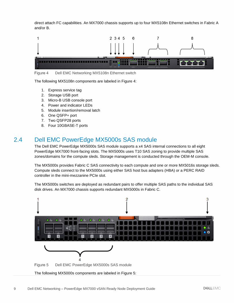
direct attach FC capabilities. An MX7000 chassis supports up to four MX5108n Ethernet switches in Fabric A and/or B.
Dell EMC Networking MX5108n Ethernet switch
The following MX5108n components are labeled in Figure 4:
1. Express service tag 2. Storage USB port 3. Micro-B USB console port 4. Power and indicator LEDs 5. Module insertion/removal latch 6. One QSFP+ port 7. Two QSFP28 ports 8. Four 10GBASE-T ports
2.4 Dell EMC PowerEdge MX5000s SAS module The Dell EMC PowerEdge MX5000s SAS module supports a x4 SAS internal connections to all eight PowerEdge MX7000 front-facing slots. The MX5000s uses T10 SAS zoning to provide multiple SAS zones/domains for the compute sleds. Storage management is conducted through the OEM-M console.
The MX5000s provides Fabric C SAS connectivity to each compute and one or more MX5016s storage sleds. Compute sleds connect to the MX5000s using either SAS host bus adapters (HBA) or a PERC RAID controller in the mini-mezzanine PCIe slot.
The MX5000s switches are deployed as redundant pairs to offer multiple SAS paths to the individual SAS disk drives. An MX7000 chassis supports redundant MX5000s in Fabric C.
Dell EMC PowerEdge MX5000s SAS module
The following MX5000s components are labeled in Figure 5:

10 Dell EMC Networking – PowerEdge MX7000 vSAN Ready Node Deployment Guide
1. Express service tag 2. Module insertion/removal latch 3. Power and indicator LEDs 4. Six SAS ports
2.5 Dell EMC PowerEdge MX9002m module The Dell EMC MX9002m module controls overall chassis power, cooling, and hosts the OpenManage Enterprise - Modular Edition (OME-M) console. Two external Ethernet ports are provided to allow management connectivity and to connect additional MX7000 chassis in a single logical chassis. An MX7000 supports two MX9002m modules for redundancy. Figure 6 shows a single MX9002m module and its components.
Dell EMC PowerEdge MX9002m module
The following MX9002m module components are labeled in Figure 6:
1. Handle release 2. Gigabit Ethernet port 1 3. Gigabit Ethernet port 2 4. ID button and health status LED 5. Power status LED 6. Micro-B USB port
2.6 Dell EMC PowerEdge MX740c (vSAN Ready Node) The PowerEdge MX740c is a two-socket, full-height, single-width compute sled offering impressive performance and scalability. It is ideal for dense virtualization environments and can serve as a foundation for collaborative workloads. An MX7000 chassis supports up to eight MX740c sleds.
PowerEdge MX740c key features include:
• Single-width slot design • Two CPU sockets • 24 DIMM slots of DDR4 memory

11 Dell EMC Networking – PowerEdge MX7000 vSAN Ready Node Deployment Guide
• Boot options include BOSS-S1 or IDSDM • Up to six SAS/SATA SSD/HDD and NVMe PCIe SSDs • Two PCIe mezzanine card slots for connecting to network Fabric A and B • One PCIe mini-mezzanine card slot for connecting to storage Fabric C • iDRAC9 with Lifecycle Controller
Dell EMC PowerEdge MX740c sled with six 2.5-inch SAS drives
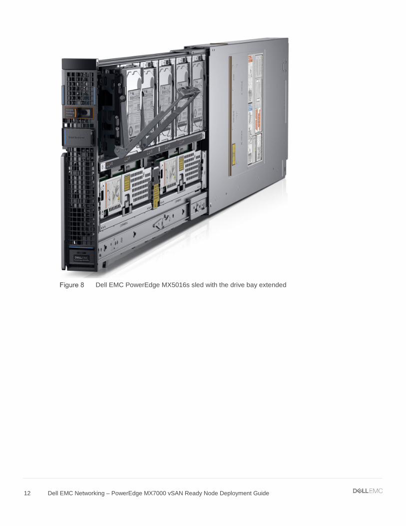
2.7 Dell EMC PowerEdge MX5016s storage Sled The PowerEdge MX5016s sled delivers scale-out, shared storage within the PowerEdge MX architecture. The MX5016s provides customizable 12 Gb/s direct-attached SAS storage with up to 16 HDDs/SSDs. Both the MX740c and the MX840c sleds can share drives with the MX5016s using the dedicated PowerEdge MX5000s SAS module. Internal server drives may be combined with up to seven MX5016s sleds in one chassis for extensive scalability. An MX7000 chassis supports up to seven MX5016s storage sleds.
12 Dell EMC Networking – PowerEdge MX7000 vSAN Ready Node Deployment Guide
Dell EMC PowerEdge MX5016s sled with the drive bay extended
13 Dell EMC Networking – PowerEdge MX7000 vSAN Ready Node Deployment Guide
3 Topology overview This section provides information about the two solutions that are used in this document. Both topologies use a single chassis to deploy vSAN Ready Nodes. The first topology is suited for small scale deployments where most of the networking, storage, and compute is located within the chassis. The second topology is suited for larger scale deployments where the chassis is part of a data center network with more racks of storage and compute resources.
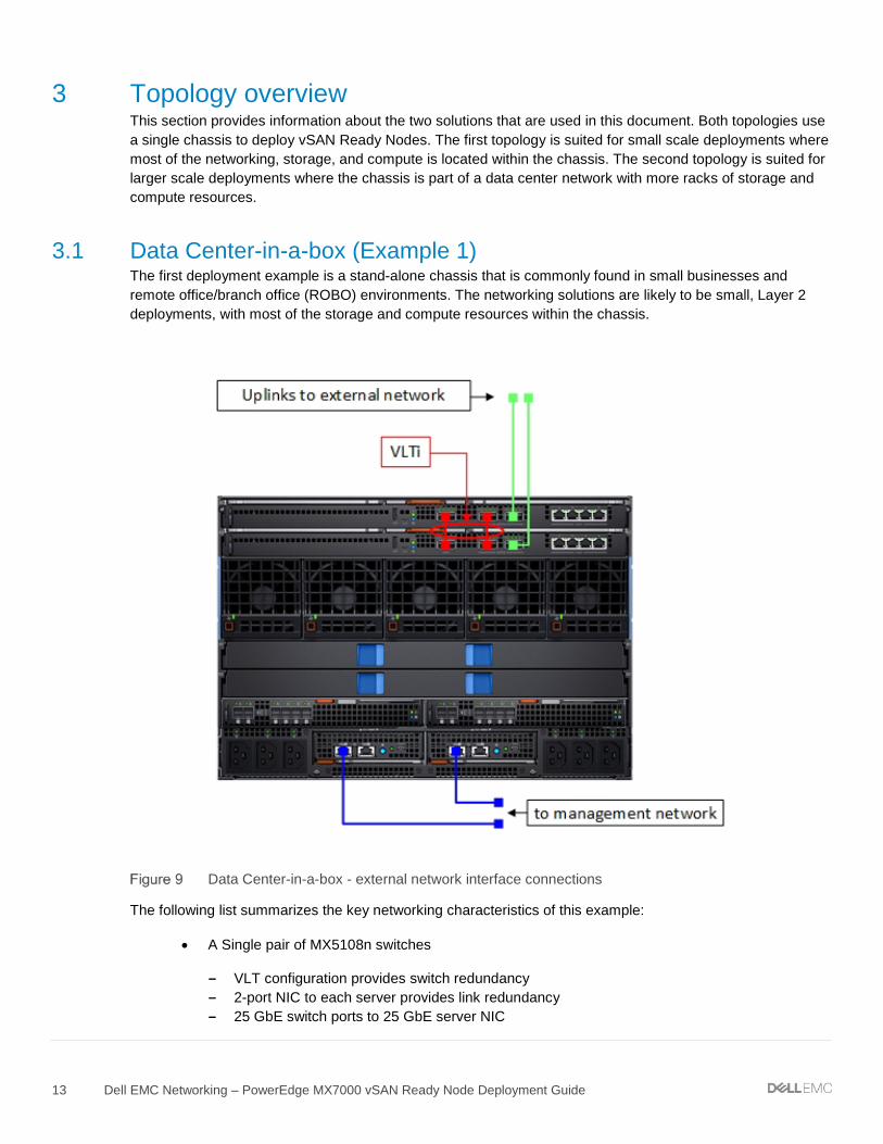
3.1 Data Center-in-a-box (Example 1) The first deployment example is a stand-alone chassis that is commonly found in small businesses and remote office/branch office (ROBO) environments. The networking solutions are likely to be small, Layer 2 deployments, with most of the storage and compute resources within the chassis.
Data Center-in-a-box - external network interface connections
The following list summarizes the key networking characteristics of this example:
• A Single pair of MX5108n switches
- VLT configuration provides switch redundancy - 2-port NIC to each server provides link redundancy - 25 GbE switch ports to 25 GbE server NIC

14 Dell EMC Networking – PowerEdge MX7000 vSAN Ready Node Deployment Guide
- 100 GbE switch uplink port per switch to an external network
• vSAN considerations
- vSAN, management, vMotion, and all compute traffic on the same link
• Storage
- MX5016s Storage Sled provides up to 16 extra SAS drives - MX5000s SAS module enables the use of storage sled and external SAS storage (not
shown)
Figure 10 shows the connections of a single server internal to the MX7000 chassis. This diagram is to help in understanding the types of traffic present on the links from the server to the MX switches. The combination of MX switch configuration and virtual networking settings within vSphere controls the traffic types.
A logical representation of a server to switch networking for Data Center-in-a-box example
3.2 Chassis in leaf-spine (Example 2) The second deployment example is a stand-alone chassis that is found in medium to large data center environments. This topology is suited for customers that want to deploy a stand-alone chassis into an established network such as a leaf-spine network commonly found in large data centers. This solution can be modified to deploy into a Layer 2 or Layer 3 leaf-spine.

15 Dell EMC Networking – PowerEdge MX7000 vSAN Ready Node Deployment Guide
Chassis in leaf-spine – external network connections
The following list summarizes the key networking characteristics of this example:
• Two pairs of MX5108n switches
- VLT configuration provides switch redundancy - Two 2-port NICs on each server provides link redundancy to each switch - 25 GbE switch ports to 25 GbE server NICs - 100 GbE switch uplink port per switch to an external network - The second switch is used to segregate and provide dedicated links for vSAN storage traffic
• vSAN considerations
- vSAN storage traffic on dedicated links and switch - Management, vMotion, and all compute traffic on a separate link and switch
The following logical diagram shows the connections of a single server internal to the MX7000 chassis. This diagram is to help in understanding the types of traffic present on the links from the server to the MX switches. The combination of MX switch configuration and virtual networking settings within vSphere controls the traffic types.

16 Dell EMC Networking – PowerEdge MX7000 vSAN Ready Node Deployment Guide
A logical representation of server to switch networking for Chassis in leaf-spine example

17 Dell EMC Networking – PowerEdge MX7000 vSAN Ready Node Deployment Guide
4 Example 1 – Data Center-in-a-box This section provides step-by-step instruction on configuration of networking related settings to deploy a vSAN within the MX7000 chassis. Topology diagrams and information about this example are in Section 3.1
4.1 Chassis setup requirements This section provides initial conditions of the chassis, servers, and storage sled before beginning network configuration. The installation and setup of the chassis and servers are not within the scope of this document.
Initial MX7000 chassis and server conditions:
• MX7000 chassis installed and powered on (includes two MX9002m modules) • MX740c vSAN Ready Node servers (4qty) installed in chassis • MX5016s storage sled installed in chassis • MX5108n switches installed in fabric A1 and A2 • MX5000s Storage I/O modules installed in fabric C1 and C2 • MX7000 chassis management access configured (IP addresses assigned to chassis
management) • MX5016s HDD/SSD disks are assigned to appropriate servers • Best practice- Update all associated firmware and software
Note: This document does not provide steps to configure management access to the MX7000 chassis. Access to the switch command line can be accomplished through the MX9002m on a management network, or through the USB serial port on the front panel of the switch. Instructions on setting MX9002m and MX switch management IP addresses can be found in the Dell EMC OpenManage Enterprise-Modular Edition Version 1.00.01 for PowerEdge MX Chassis User's Guide or Dell EMC PowerEdge MX Ethernet Networking Deployment Guide.
4.2 vSAN networking recommendations This section lists the networking recommendations that are used in vSAN clusters. These recommendations can be found in the VMware Validated Design for Software-Defined Data Center (SDDC) documentation at VMware Validated Design Documentation. These recommendations are listed here for reference only.
The following recommendations do not encompass the entire set of design decisions for the SDDC:
• CSDDC-PHY-NET-003: Use two ToR switches for each rack to provide redundancy • CSDDC-PHY-NET-004: Use VLANs to segment physical network functions • CSDDC-PHY-NET-008: Configure the MTU size to at least 9000 bytes (jumbo frames) on the
physical switch ports and distributed switch port groups that support vSAN and vMotion traffic • CSDDC-VI-NET-001: Use vSphere Distributed Switch (vDS) • CSDDC-VI-NET-003: Use the route that is based on the physical NIC load teaming algorithm for
all port groups except for ones that carry VXLAN traffic. VTEP kernel ports and VXLAN traffic use route based on SRC-ID
• CSDDC-VI-Storage-SDS-001: Use only 10 GbE or higher for vSAN traffic • CSDDC-VI-Storage-SDS-003: Configure jumbo frames on the VLAN dedicated to vSAN traffic

18 Dell EMC Networking – PowerEdge MX7000 vSAN Ready Node Deployment Guide
• CSDDC-VI-Storage-SDS-004: Use a dedicated VLAN for vSAN traffic for each vSAN enabled cluster
• Administering VMware vSAN (VMware vSAN 6.7) recommends the using the teaming algorithm Route based on physical network adapter load, the recommended failover configuration is Active/Active
4.3 Switch configuration This section provides steps to configure Dell EMC Networking MX5108n switches running Dell Networking operating system 10.4.0E (R3S). The process requires basic familiarity with OS10 configuration and network switches.
4.3.1 Check switch operating system version Use the following command to verify that the operating system version on the switch is 10.4.0E (R3S) or later: If not, go to www.force10networks.com or www.dell.com/support/software to download the latest operating system version for the switch.
OS10# show version Dell EMC Networking OS10 Enterprise Copyright (c) 1999-2018 by Dell Inc. All Rights Reserved. OS Version: 10.4.0E.R3S Build Version: 10.4.0E.R3S.268 Build Time: 2018-07-12T00:29:26-0700 System Type: MX5108N-ON Architecture: x86_64 Up Time: 2 days 00:43:49
4.3.2 Factory default configuration (optional) Enter the following commands to set the switch to factory defaults:
OS10# delete startup-configuration Proceed to delete startup-configuration [confirm yes/no(default)]:yes OS10# reload System configuration has been modified. Save? [yes/no]:no Continuing without saving system configuration Proceed to reboot the system? [confirm yes/no]: yes
The switch reboots with factory default settings and is ready to configure using the default username and password of admin/admin.
4.3.3 Switch management settings (GUI) Ensure that the MX chassis and switches are powered on and operational, and management access has been established.
To configure the IOM-A1 switch, use the OpenManage Enterprise Modular GUI and select the IO Modular Slot A1 device. The following figure shows the IOM-A1 network settings page on the OpenManage Enterprise Modular GUI:

19 Dell EMC Networking – PowerEdge MX7000 vSAN Ready Node Deployment Guide
Note: The default configuration for switch management is DHCP. Figure 13 shows an example of a configuration using static IP address settings.
IOM-A1 management network settings
4.3.4 Switch configuration (CLI) MX switches operate in one of two modes, Full Switch or SmartFabric. Ensure that the switch is operating in Full Switch mode for these examples. For additional information about switch modes, see Dell EMC PowerEdge MX Network Architecture Guide.
OS10# show switch-operating-mode Switch-Operating-Mode: Full Switch Mode
Table 2 contains example VLAN and IP address information. Use the addresses in Table 2 throughout the switch configuration steps.
Table 2 VLAN and IP addresses used in example configurations
Purpose VLAN IOM-A1 IOM-A2 VRRP (gateway)
OOB switch management NA 100.67.164.171 100.67.164.172 NA
ESXi management 2030 172.20.30.251 /24 172.20.30.252 /24 172.20.30.253
vMotion 2031 172.20.31.251 /24 172.20.31.252 /24 172.20.31.253
vSAN 2032 172.20.32.251 /24 172.20.32.252 /24 172.20.32.253
Note: IP addresses are provided in the example configuration commands throughout this document. The addresses are used in a lab setting and are not intended as a recommendation for production use.
Configure the hostnames on the switches:
20 Dell EMC Networking – PowerEdge MX7000 vSAN Ready Node Deployment Guide
1. Access the command line of both MX5108n switches, IOM-A1 and IOM-A2. 2. Configure a hostname of IOM-A1:
OS10# configure terminal OS10(config)# hostname IOMA1 IOMA1(config)#
3. Repeat step 2 for IOM-A2.
Configure the interface breakout settings used for the VLTi links. This setting configures the combination of speed and breakout interfaces of the front-panel Ethernet port.
1. Configure the VLTi interfaces:
IOMA1(config)# interface breakout 1/1/9 map 40g-1x IOMA1(config)# interface breakout 1/1/10 map 40g-1x
2. Repeat step 1 for IOM-A2.
Note: The uplink interface (port 1/1/11) can also be configured for the desired interface breakout setting. The uplink interface is not documented in this example. A single 100 GbE or 2 x 50 GbE is recommended, depending on the redundancy requirements and infrastructure available. Four 10GBASE-T ports are also available.
4.3.5 VLT configuration In this example, configure the VLT interconnect (VLTi) between the two Dell EMC MX5108n switches. VLT synchronizes Layer 2 table information between the switches and enables them to display as a single logical unit from outside the VLT domain.
Use VRRP for gateway redundancy with vSAN and management VLANs. VRRP` is an active/standby first hop redundancy protocol (FHRP). When used among VLT peers, it becomes active/active. Both VLT peers have the VRRP virtual MAC address in their FIB table as the local destination address. This enables the backup VRRP router to forward intercepted frames whose destination MAC address matches the VRRP virtual MAC address.
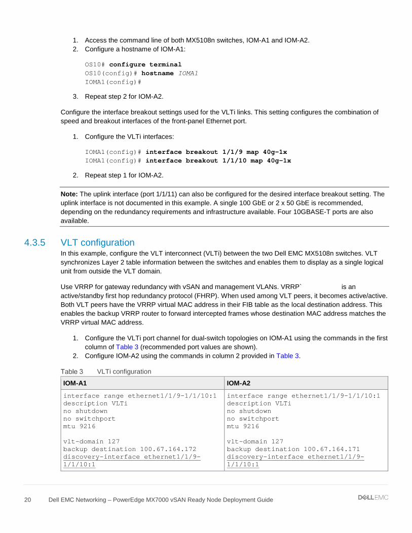
1. Configure the VLTi port channel for dual-switch topologies on IOM-A1 using the commands in the first column of Table 3 (recommended port values are shown).
2. Configure IOM-A2 using the commands in column 2 provided in Table 3.
VLTi configuration
IOM-A1 IOM-A2
interface range ethernet1/1/9-1/1/10:1 description VLTi no shutdown no switchport mtu 9216 vlt-domain 127 backup destination 100.67.164.172 discovery-interface ethernet1/1/9-1/1/10:1
interface range ethernet1/1/9-1/1/10:1 description VLTi no shutdown no switchport mtu 9216 vlt-domain 127 backup destination 100.67.164.171 discovery-interface ethernet1/1/9-1/1/10:1

21 Dell EMC Networking – PowerEdge MX7000 vSAN Ready Node Deployment Guide
Note: If implementing Layer 3 routing on the switch (not shown), use the command peer-routing within the vlt-domain configuration.
4.3.6 VLAN configuration Configure the VLAN interfaces and Virtual Router Redundancy Protocol (VRRP). VRRP is used as a secondary form of redundancy.
VLAN configuration
IOM-A1 IOM-A2
interface vlan2030 description ESXimanagement no shutdown mtu 9216 ip address 172.20.30.251/24 vrrp-group 30 virtual-address 172.20.30.253 interface vlan2031 description vMotion no shutdown mtu 9216 ip address 172.20.31.251/24 vrrp-group 31 virtual-address 172.20.31.253 interface vlan2032 description vSAN no shutdown mtu 9216 ip address 172.20.32.251/24 vrrp-group 32 virtual-address 172.20.32.253
interface vlan2030 description ESXimanagement no shutdown mtu 9216 ip address 172.20.30.252/24 vrrp-group 30 virtual-address 172.20.30.253 interface vlan2031 description vMotion no shutdown mtu 9216 ip address 172.20.31.252/24 vrrp-group 31 virtual-address 172.20.31.253 interface vlan2032 description vSAN no shutdown mtu 9216 ip address 172.20.32.252/24 vrrp-group 32 virtual-address 172.20.32.253
4.3.7 Node-facing configuration Configure the vSAN node-facing interfaces with the following steps.
Node-facing configuration
IOM-A1 IOM-A2
interface ethernet1/1/1 description "vSAN node 1 Port 1" no shutdown switchport mode trunk switchport access vlan 2030 switchport trunk allowed vlan 2031-2032 mtu 9216 spanning-tree port type edge interface ethernet1/1/2 description "vSAN node 2 Port 1” no shutdown switchport mode trunk switchport access vlan 2030
interface ethernet1/1/1 description "vSAN node 1 Port 2” no shutdown switchport mode trunk switchport access vlan 2030 switchport trunk allowed vlan 2031-2032 mtu 9216 spanning-tree port type edge interface ethernet1/1/2 description "vSAN node 2 Port 2” no shutdown switchport mode trunk switchport access vlan 2030
22 Dell EMC Networking – PowerEdge MX7000 vSAN Ready Node Deployment Guide
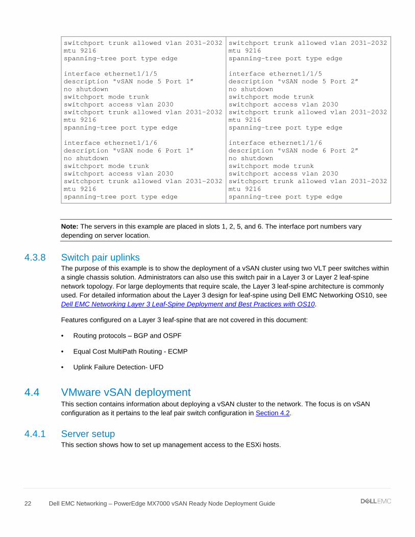
switchport trunk allowed vlan 2031-2032 mtu 9216 spanning-tree port type edge interface ethernet1/1/5 description "vSAN node 5 Port 1” no shutdown switchport mode trunk switchport access vlan 2030 switchport trunk allowed vlan 2031-2032 mtu 9216 spanning-tree port type edge interface ethernet1/1/6 description "vSAN node 6 Port 1” no shutdown switchport mode trunk switchport access vlan 2030 switchport trunk allowed vlan 2031-2032 mtu 9216 spanning-tree port type edge
switchport trunk allowed vlan 2031-2032 mtu 9216 spanning-tree port type edge interface ethernet1/1/5 description "vSAN node 5 Port 2” no shutdown switchport mode trunk switchport access vlan 2030 switchport trunk allowed vlan 2031-2032 mtu 9216 spanning-tree port type edge interface ethernet1/1/6 description "vSAN node 6 Port 2” no shutdown switchport mode trunk switchport access vlan 2030 switchport trunk allowed vlan 2031-2032 mtu 9216 spanning-tree port type edge
Note: The servers in this example are placed in slots 1, 2, 5, and 6. The interface port numbers vary depending on server location.
4.3.8 Switch pair uplinks The purpose of this example is to show the deployment of a vSAN cluster using two VLT peer switches within a single chassis solution. Administrators can also use this switch pair in a Layer 3 or Layer 2 leaf-spine network topology. For large deployments that require scale, the Layer 3 leaf-spine architecture is commonly used. For detailed information about the Layer 3 design for leaf-spine using Dell EMC Networking OS10, see Dell EMC Networking Layer 3 Leaf-Spine Deployment and Best Practices with OS10.
Features configured on a Layer 3 leaf-spine that are not covered in this document:
• Routing protocols – BGP and OSPF
• Equal Cost MultiPath Routing - ECMP
• Uplink Failure Detection- UFD
4.4 VMware vSAN deployment This section contains information about deploying a vSAN cluster to the network. The focus is on vSAN configuration as it pertains to the leaf pair switch configuration in Section 4.2.
4.4.1 Server setup This section shows how to set up management access to the ESXi hosts.

23 Dell EMC Networking – PowerEdge MX7000 vSAN Ready Node Deployment Guide
To configure the management interface on the ESXi hosts:
1. Access the console through the iDRAC on the server. 2. Log in to ESXi. 3. Select Configure Management Network. 4. Select Network Adapters. 5. Choose vmnic0 Mezzanine 1A.
ESXi Network Adapter setting
6. Press the Enter key. 7. Select IPv4 Configuration. 8. Select Set static IPv4 address and network configuration. 9. Enter IPv4 Address 172.20.30.101 10. Enter Subnet Mask 255.255.255.0 11. Enter Default Gateway 172.20.30.253
ESXi IPv4 Configuration
24 Dell EMC Networking – PowerEdge MX7000 vSAN Ready Node Deployment Guide
12. Press the Enter key. 13. Select DNS Configuration. 14. Select Use the following DNS server addresses and hostname. 15. Enter a Primary DNS Server (example: 172.16.11.5). 16. (Optional) Enter an Alternate DNS Server. 17. Enter a Hostname (example: MXvSAN01). 18. Press the Enter key. 19. Press the Esc key to exit. 20. Apply changes and restart the network. 21. Repeat the steps in this section for servers 2,3, and 4.
Note: A Windows Server 2016 DNS service is accessible by all hosts in this deployment example. Host (A) records for forward lookup zones, and Pointer (PTR) records for reverse lookup zones are configured for each ESXi host and the vCenter appliance. DNS server administration and installation are not within the scope of this document. DNS is a requirement for the vCenter Server Appliance.
4.4.2 vCenter install with vSAN This section details the installation of vCenter Server and vSAN using the vCSA installation GUI.
1. Download the appropriate vCSA ISO at https://my.vmware.com 2. Using the vCenter Server Appliance Installer GUI, run the installer on a workstation that can reach
the management network of the ESXi hosts.
Note: To access the management network of the ESXi hosts, a server is used as a jump box, or a workstation can be used. Configure the external network uplink or use a 10GBASE-T interface on the MX5108n switches. (not shown)
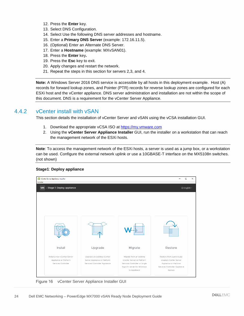
Stage1: Deploy appliance
vCenter Server Appliance Installer GUI

25 Dell EMC Networking – PowerEdge MX7000 vSAN Ready Node Deployment Guide
1. Click Install. 2. Click NEXT 3. Review the information provided within the license agreement and if you accept the terms listed, click
NEXT. 4. Keep default selection of Embedded Platform Services Controller, then click NEXT. 5. Enter the required information for hostname, User name, and Password, then click NEXT. 6. Enter the required VM name and root password, then click NEXT. 7. Pick an appropriate deployment size, then click NEXT.
Note: This example uses Deployment size of Tiny and Storage size of Default.
8. Select Install a new vSAN cluster containing the target host and enter the appropriate information for Datacenter name and Cluster name, then click NEXT.
9. To claim disks for vSAN, select the remaining disks, and set them as Capacity tier. 10. Set the remaining disk as Cache tier, then click NEXT.
Claim disks for vSAN
Note: The screenshot in Figure 17 is not a production example and is used to demonstrate the installation process. The disk configuration for production models can change. Use vSAN cache and capacity guidelines when designing a production ready vSAN cluster. See Administering VMware vSAN.
11. Enter the appropriate information for the network, FQDN, IP address, mask, gateway, and DNS, and then click NEXT.
12. Click FINISH. The vSAN Datastore is created, and the first stage of vCenter deploys.
26 Dell EMC Networking – PowerEdge MX7000 vSAN Ready Node Deployment Guide
Stage 2: Set up vCenter Server Appliance
1. Continue within the installer, or access using a web browser. 2. Appliance configuration, confirm, and modify as needed, Click NEXT. 3. SSO configuration, enter a password, Click NEXT. 4. Configure CEIP, Click NEXT. 5. Review Ready to complete, Click FINISH.
4.4.3 Configure hosts – assign disks from storage sled This section details steps to assign drives from the MX5016s storage sled to the vSAN Ready Nodes. This step can be done at any time before adding these drives to the vSAN cluster.
Note: The storage sled is optional. If a storage sled is not used, go to the next section.
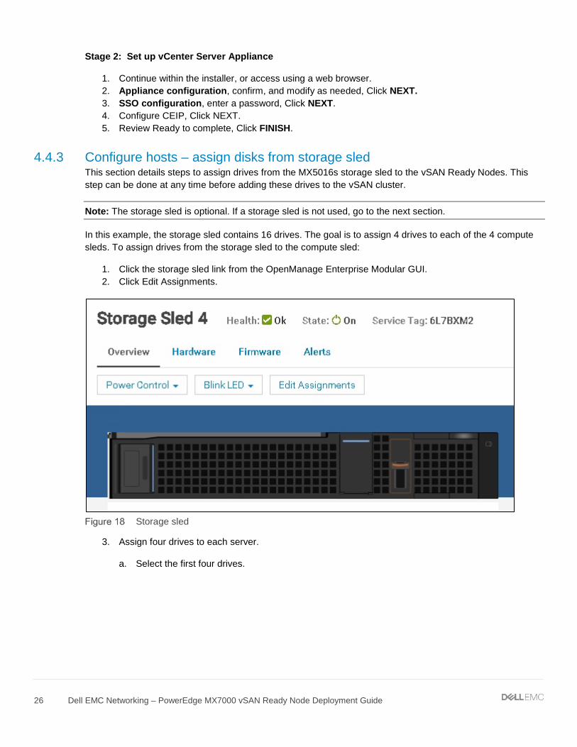
In this example, the storage sled contains 16 drives. The goal is to assign 4 drives to each of the 4 compute sleds. To assign drives from the storage sled to the compute sled:
1. Click the storage sled link from the OpenManage Enterprise Modular GUI. 2. Click Edit Assignments.
Storage sled
3. Assign four drives to each server.
a. Select the first four drives.

27 Dell EMC Networking – PowerEdge MX7000 vSAN Ready Node Deployment Guide
Select four drives
b. Click Assign Drive to Slot. c. Select Sled-1 server. d. Click Assign.
Assigning drives to slot
4. Repeat step 3 for the next four drives, assign to Sled-2. 5. Repeat step 3 for the next four drives, assign to Sled-5. 6. Repeat step 3 for the last four drives, assign to Sled-6.
Note: In the GUI screenshots, servers are shown in slots 1, 2, 5, and 6. The example uses these locations throughout the deployment steps.
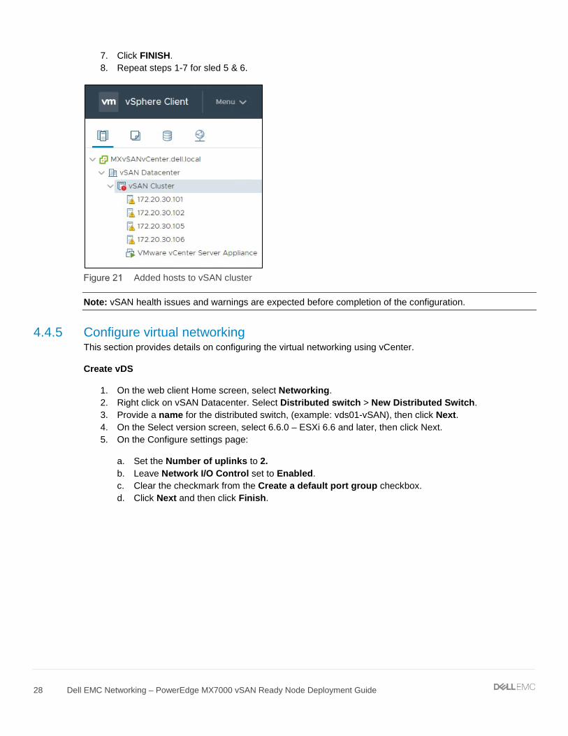
4.4.4 Add hosts to vSAN cluster This section details adding hosts to the vSAN cluster.
To add hosts to the vSAN cluster created during the vCenter install:
1. Right click on the vSAN Cluster, select Add Host. 2. Enter the Hostname or IP address of sled 2, click NEXT. 3. Enter the username and password, click NEXT. 4. Review summary, click NEXT. 5. Assign a license, click NEXT. 6. Select desired lockdown mode, keep as disabled for now, click NEXT.
28 Dell EMC Networking – PowerEdge MX7000 vSAN Ready Node Deployment Guide
7. Click FINISH. 8. Repeat steps 1-7 for sled 5 & 6.
Added hosts to vSAN cluster
Note: vSAN health issues and warnings are expected before completion of the configuration.
4.4.5 Configure virtual networking This section provides details on configuring the virtual networking using vCenter.
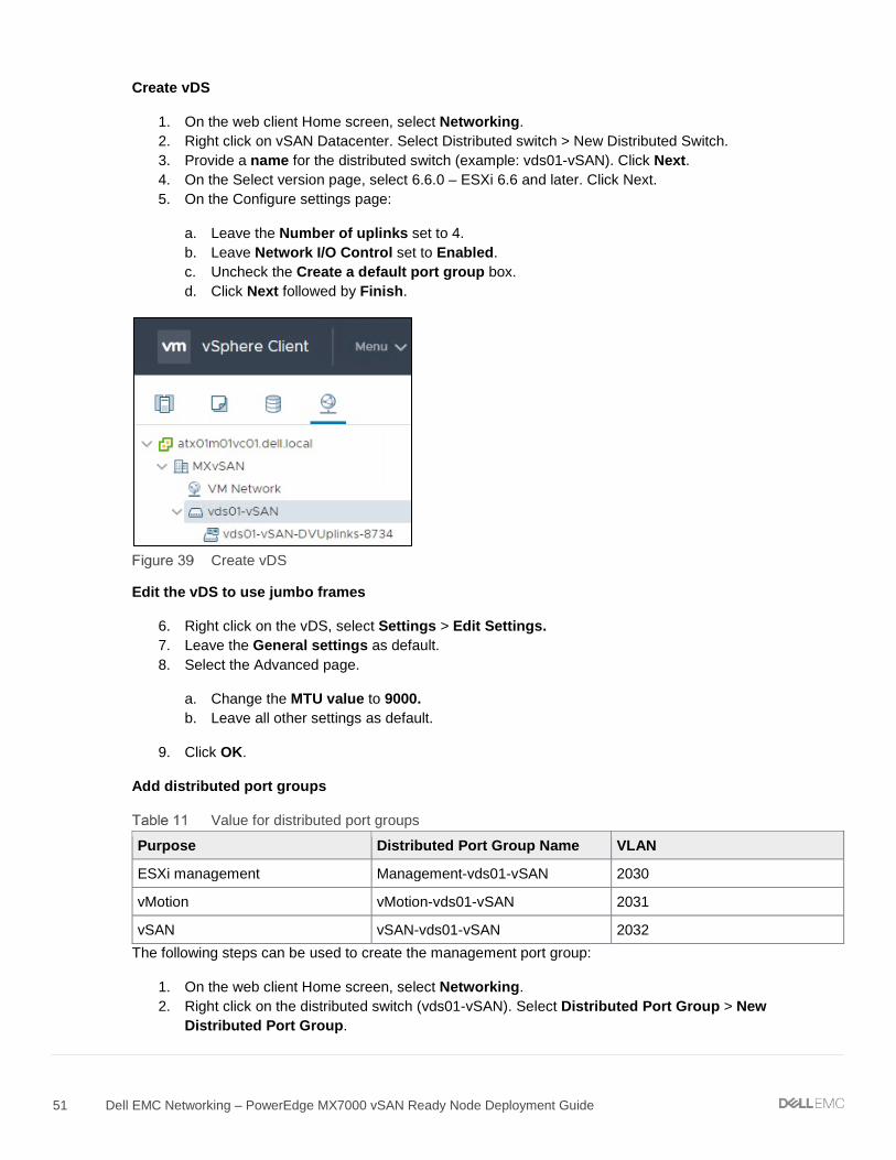
Create vDS
1. On the web client Home screen, select Networking. 2. Right click on vSAN Datacenter. Select Distributed switch > New Distributed Switch. 3. Provide a name for the distributed switch, (example: vds01-vSAN), then click Next. 4. On the Select version screen, select 6.6.0 – ESXi 6.6 and later, then click Next. 5. On the Configure settings page:
a. Set the Number of uplinks to 2. b. Leave Network I/O Control set to Enabled. c. Clear the checkmark from the Create a default port group checkbox. d. Click Next and then click Finish.

29 Dell EMC Networking – PowerEdge MX7000 vSAN Ready Node Deployment Guide
Create vDS
Edit the vDS to use jumbo frames
1. Right click on the vDS, select Settings > Edit Settings. 2. Leave the General settings as default. 3. Select the Advanced page.
a. Change the MTU value to 9000. b. Leave all other settings as default.
Click OK.
Add distributed port groups
Values for distributed port groups
Purpose Distributed Port Group Name VLAN
ESXi management Management-vds01-vSAN 2030
vMotion vMotion-vds01-vSAN 2031
vSAN vSAN-vds01-vSAN 2032
The following steps can be used to create the management port group:
1. On the web client Home screen, select Networking. 2. Right click on the distributed switch (vds01-vSAN). 3. Select Distributed Port Group and then select New Distributed Port Group. 4. On the Select name and location page, provide a Name for the distributed port group (example:
Management-vds01-vSAN). Click Next. 5. On the Configure settings page, keep all values as default, leaving VLAN type as None. Click
Next. (VLAN 2030 is not assigned on this port group since it’s the default access VLAN on the switch interfaces).
6. Click Finish.

30 Dell EMC Networking – PowerEdge MX7000 vSAN Ready Node Deployment Guide
The following steps can be used to create the vMotion and vSAN port groups:
1. On the web client Home screen, select Networking. 2. Right click on the distributed switch (vds01-vSAN). Select Distributed Port Group > New
Distributed Port Group. 3. On the Select name and location page, provide a Name for the distributed port group (example:
vMotion-vds01-vSAN). Click Next. 4. On the Configure settings page, set the VLAN type as VLAN, enter the appropriate VLAN ID
(2031). Click Next. 5. Click Finish. 6. Create the final Distributed Port Group (vSAN-vds01-vSAN) using the values in Table 6.
After creating the distributed port groups (using example values), the configuration looks like Figure 23.
Distributed Port Groups
Configure teaming and failover on uplinks
1. On the web client Home screen, select Networking. 2. Right click on the distributed switch, and then select Distributed Port Group > Manage Distributed
Port Groups. 3. Select only the Teaming and failover check box, and then click Next. 4. Click Select distributed port groups. Check the top box to select all three port groups and click Next. 5. On the Teaming and failover page:
a. For Load balancing, select Route based on physical NIC load. b. For Failover order, confirm Uplink 1 and Uplink 2 are both under the Active uplinks section.
Leave other settings at their defaults. An example is shown in Figure 24.
6. Click Next, then Finish to apply the settings.

31 Dell EMC Networking – PowerEdge MX7000 vSAN Ready Node Deployment Guide
Teaming and failover settings for distributed port groups
Add and manage hosts to the vDS
1. On the web client Home screen, select Networking. 2. Right-click on the distributed switch and select Add and Manage Hosts. 3. On the Select task page, verify that Add hosts is selected, and then click Next. 4. On the Select hosts page, click New hosts, and then select the check box next to each host in the
vSAN cluster. 5. Click OK, and then click Next. 6. On the Manage physical network adapters page, each host is listed with its vmnics beneath it.
a. vmnic0 is in use by vSwitch0 and is currently used for management.
Note: Do not change settings for vmnic0 at this time. This will cause the tasks executed by the wizard to fail and leads to a disconnected ESXi host.
b. Select vmnic1 on the first host and click c. Select Uplink 2 and then click OK. d. Repeat sub steps a through d to configure the remaining hosts, and then click Next.

32 Dell EMC Networking – PowerEdge MX7000 vSAN Ready Node Deployment Guide
Manage physical adapters
7. On the Manage VMkernel network adapters page, each host is listed with its VMkernel adapters beneath it. Only the default ESXi management VMkernel (vmk0) is present.
a. Leave all settings as default. Click NEXT.
Note: The management kernel will be migrated in another step.
8. On the Migrate VM networking page, the vCenter Server Appliance is listed.
a. Leave all settings as default. The VM network is migrated in another step. Click NEXT.
9. Review the Ready to complete summary. Click Finish.
Migrate VM networking for vCenter Appliance Server
1. On the web client Home screen, select Networking. 2. Right-click the distributed switch and select Add and Manage Hosts. 3. On the Select task page, make sure Manage host networking is selected, then click NEXT. 4. On the Select hosts page, click Attached hosts, and then select the check box next to the host that
has the vCenter VM (example: host 172.20.30.101). 5. Click OK, then click Next. 6. On the Manage physical adapters page, make no changes, click NEXT. 7. On the Manage VMkernel adapters page, make no changes, click NEXT. 8. On the Migrate VM networking page, the vCenter Server Appliance is listed,
a. Select Network adapter 1 and click on b. Select the Management-vds01-vSAN port group, Click OK.

33 Dell EMC Networking – PowerEdge MX7000 vSAN Ready Node Deployment Guide
c. Click NEXT.
Migrate VM networking
9. Review the Ready to complete summary. Click Finish.
Move management kernel to vDS for each host
1. On the web client Home screen, select Networking. 2. Right-click on the distributed switch and select Add and Manage Hosts. 3. On the Select task page, make sure Manage host networking selected, then click Next. 4. On the Select hosts page, click Attached hosts, then select the check box next to each host in the
vSAN cluster. 5. Click OK, then click Next. 6. On the Manage physical adapters page, make no changes, click NEXT. 7. On the Manage VMkernel adapters page migrate the management kernel.
a. Select the ESXi management VMkernel adapter, vmk0, on the first host and click
b. Choose the management port group (example: Management-vds01-vSAN). Click OK. c. Repeat steps 7.a. - 7.b. for each of the remaining hosts in the vSAN cluster.

34 Dell EMC Networking – PowerEdge MX7000 vSAN Ready Node Deployment Guide
Manage VMkernel adapters
8. Click NEXT. 9. On the Migrate VM networking page, make no changes, click NEXT. 10. Review the Ready to complete summary. Click Finish.
Move vmnic0 from vSwitch0 to vDS Uplink1.
1. On the web client Home screen, select Networking. 2. Right-click on the distributed switch and select Add and Manage Hosts. 3. On the Select task page, make sure Manage host networking selected, then click NEXT. 4. On the Select hosts page, click Attached hosts, then select the check box next to each host in the
vSAN cluster. 5. Click OK, then click NEXT. 6. On the Manage physical adapters page, each host is listed with its vmnics beneath it.
a. Select vmnic0 on the first host and click b. Select Uplink1 then click OK. c. vmnic1 was configured in the previous set of steps and is in its final configuration state. Do not
change settings for vmnic1.
7. Repeat sub steps a through d to configure the remaining hosts, then click NEXT.

35 Dell EMC Networking – PowerEdge MX7000 vSAN Ready Node Deployment Guide
Migrate vmnic0
8. On the Manage VMkernel adapters page, make no changes, click NEXT. 9. On the Migrate VM networking page, make no changes, click NEXT. 10. Review the Ready to complete summary. Click Finish.
Add VMkernels to vSAN port group
1. On the web client Home screen, select Networking. 2. Right-click on the vSAN-vds01-vSAN port group. 3. Select Add VMkernel Adapters. 4. On the Select hosts page, click Attached hosts, then select the check box next to each host in the
vSAN cluster. 5. Click OK, then click NEXT. 6. On the Configure VMkernel adapter page:
a. Set the MTU to Custom and enter a value of 9000. b. For Available Services, check the vSAN box. c. Click NEXT.
7. On the IPv4 settings page:
a. Select Use static IPv4 settings. b. Enter in an IPv4 address for each host. (example: 172.20.32.101 255.255.255.0, etc…) c. For Gateway, choose Configure on VMkernel adapters, and enter a gateway. (example:
172.20.32.253). d. Click NEXT.

36 Dell EMC Networking – PowerEdge MX7000 vSAN Ready Node Deployment Guide
Add vSAN VMkernel
8. Review the Ready to complete summary. Click Finish.
Add VMkernels to vMotion port group
1. On the web client Home screen, select Networking. 2. Right-click on the vMotion-vds01-vSAN port group. 3. Select Add VMkernel Adapters. 4. On the Select hosts page, click Attached hosts, then select the check box next to each host in the
vSAN cluster. 5. Click OK, then click NEXT. 6. On the Configure VMkernel adapter page:
a. Set the MTU to Custom and enter a value of 9000. b. For Available Services, check the vMotion box. c. Click NEXT.
7. On the IPv4 settings page:
a. Select Use static IPv4 settings. b. Enter in a IPv4 address for each host. (example: 172.20.31.101 255.255.255.0, etc…) c. For Gateway, choose Configure on VMkernel adapters, and enter a gateway (example:
172.20.31.253). d. Click NEXT.

37 Dell EMC Networking – PowerEdge MX7000 vSAN Ready Node Deployment Guide
Add vMotion VMkernel
8. Review the Ready to complete summary. Click Finish.
Add Disk Groups to vSAN
1. Click on the vSAN Cluster and select the Configure tab. 2. Under vSAN, select Disk Management. 3. A single Disk group was configured during the vCenter installation and can be seen in Figure 31.

38 Dell EMC Networking – PowerEdge MX7000 vSAN Ready Node Deployment Guide
vSAN Disk group initial view
4. Click on the host 2 row (172.20.30.102) listed in the Disk Group column.
5. Click the Create a new disk group icon above the table. 6. For this example, configure a disk group in each host using the disks installed on the servers:
a. Select a single disk to use as Cache in the first table. b. Select 5 disks to use as Capacity in the second table. c. Click CREATE.

39 Dell EMC Networking – PowerEdge MX7000 vSAN Ready Node Deployment Guide
Create a disk group
7. Repeat steps 4-6 on the remaining hosts. 8. All hosts should now have a single disk group.
Note: The first host with the vCenter Appliance server already has a disk group created during the vCenter installation process.
Add additional disk groups using disks assigned from the MX5016s storage sled.
1. Click on the vSAN Cluster and select the Configure tab. 2. Under vSAN, select Disk Management. 3. Click on the host 1 row (172.20.30.101) listed in the Disk Group column.
4. Click the Create a new disk group icon above the table. 5. For this example, configure a disk group in each host using the disks assigned to the servers:
a. Select a single disk to use as Cache in the first table. b. Select 3 disks to use as Capacity in the second table. c. Click CREATE.
Note: For production deployments, design the vSAN cluster in accordance with Administering VMware vSAN. Ensure the disk types in the storage sled comply with the disk groups in the vSAN cluster. Mixing disk group types is not supported. Disk groups must be all-flash or hybrid.
6. Repeat steps 3-5 on the remaining hosts. 7. All hosts should now have an additional disk group using the disks from the MX5016s storage sled.

40 Dell EMC Networking – PowerEdge MX7000 vSAN Ready Node Deployment Guide
Second disk group

41 Dell EMC Networking – PowerEdge MX7000 vSAN Ready Node Deployment Guide
5 Example 2 – Chassis in Leaf-Spine This section provides step-by-step instruction on the configuration of networking related settings to deploy a vSAN within the MX7000 chassis. Topology diagrams and information about this example are in Section 3.2.
5.1 Chassis setup requirements This section provides initial conditions of the chassis, servers, and storage sled before beginning network configuration. The installation and setup of the chassis and servers are not within the scope of this document.
Initial MX7000 chassis and server conditions:
• MX7000 chassis installed and powered on (includes MX9002m modules) • MX740c vSAN Ready Node servers (4qty) installed in chassis • MX5108n switches installed in fabric A1, A2, B1, and B2 • MX7000 chassis management access configured (IP addresses assigned to chassis
management) • Best practice - Update all associated firmware and software
Note: This document does not provide steps to configure management access to the MX7000 chassis. Access to the switch command line can be accomplished through the MX9002m on a management network, or through the USB serial port on the front panel of the switch. Instructions on setting MX9002m and MX switch management IP addresses can be found in the Dell EMC OpenManage Enterprise-Modular Edition Version 1.00.01 for PowerEdge MX Chassis User's Guide or Dell EMC PowerEdge MX Ethernet Networking Deployment Guide.
5.2 vSAN networking recommendations This section lists the networking recommendations that are used in vSAN clusters. These recommendations can be found in the VMware Validated Design for Software-Defined Data Center (SDDC) documentation at VMware Validated Design Documentation. These recommendations are listed here for reference only.
The following recommendations do not encompass the entire set of design decisions for the entire SDDC:
• CSDDC-PHY-NET-003: Use two ToR switches for each rack to provide redundancy • CSDDC-PHY-NET-004: Use VLANs to segment physical network functions • CSDDC-PHY-NET-008: Configure the MTU size to at least 9000 bytes (jumbo frames) on the
physical switch ports and distributed switch port groups that support vSAN and vMotion traffic • CSDDC-VI-NET-001: Use vSphere Distributed Switch (vDS) • CSDDC-VI-NET-003: Use the route that is based on the physical NIC load teaming algorithm for
all port groups except for ones that carry VXLAN traffic. VTEP kernel ports and VXLAN traffic use route based on SRC-ID
• CSDDC-VI-Storage-SDS-001: Use only 10 GbE or higher for vSAN traffic • CSDDC-VI-Storage-SDS-003: Configure jumbo frames on the VLAN dedicated to vSAN traffic • CSDDC-VI-Storage-SDS-004: Use a dedicated VLAN for vSAN traffic for each vSAN enabled
cluster
42 Dell EMC Networking – PowerEdge MX7000 vSAN Ready Node Deployment Guide
• Administering VMware vSAN (VMware vSAN 6.7) recommends using the teaming algorithm Route based on physical network adapter load, the recommended failover configuration is Active/Active
5.3 Switch configuration This section provides steps to configure Dell EMC Networking MX5108n switches running Dell Networking OS 10.4.0E (R3S). The process requires basic familiarity with OS10 configuration and network switches.
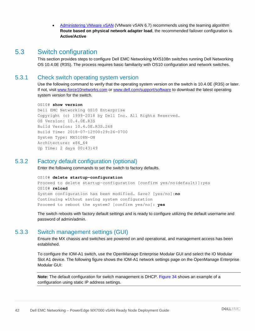
5.3.1 Check switch operating system version Use the following command to verify that the operating system version on the switch is 10.4.0E (R3S) or later. If not, visit www.force10networks.com or www.dell.com/support/software to download the latest operating system version for the switch.
OS10# show version Dell EMC Networking OS10 Enterprise Copyright (c) 1999-2018 by Dell Inc. All Rights Reserved. OS Version: 10.4.0E.R3S Build Version: 10.4.0E.R3S.268 Build Time: 2018-07-12T00:29:26-0700 System Type: MX5108N-ON Architecture: x86_64 Up Time: 2 days 00:43:49
5.3.2 Factory default configuration (optional) Enter the following commands to set the switch to factory defaults.
OS10# delete startup-configuration Proceed to delete startup-configuration [confirm yes/no(default)]:yes OS10# reload System configuration has been modified. Save? [yes/no]:no Continuing without saving system configuration Proceed to reboot the system? [confirm yes/no]: yes
The switch reboots with factory default settings and is ready to configure utilizing the default username and password of admin/admin.
5.3.3 Switch management settings (GUI) Ensure the MX chassis and switches are powered on and operational, and management access has been established.
To configure the IOM-A1 switch, use the OpenManage Enterprise Modular GUI and select the IO Modular Slot A1 device. The following figure shows the IOM-A1 network settings page on the OpenManage Enterprise Modular GUI:
Note: The default configuration for switch management is DHCP. Figure 34 shows an example of a configuration using static IP address settings.

43 Dell EMC Networking – PowerEdge MX7000 vSAN Ready Node Deployment Guide
IOM-A1 management network settings
5.3.4 Switch configuration (CLI) MX switches operate in one of two modes, Full Switch or SmartFabric. Ensure the switch is operating in Full Switch mode for these examples. For additional information on switch modes, see Dell EMC PowerEdge MX Network Architecture Guide.
OS10# show switch-operating-mode Switch-Operating-Mode : Full Switch Mode
Table 7 contains example VLAN and IP address information. The addresses below will be used throughout the switch configuration steps.
Table 2 VLAN and IP addresses used in example configurations
Purpose VLAN IOM-A1 IOM-A2 VRRP (gateway)
OOB switch management NA 100.67.164.171 100.67.164.172 NA
ESXi management 2030 172.20.30.251 /24 172.20.30.252 /24 172.20.30.253
vMotion 2031 172.20.31.251 /24 172.20.31.252 /24 172.20.31.253
Purpose VLAN IOM-B1 IOM-B2 VRRP (gateway)
OOB switch management NA 100.67.164.173 100.67.164.174 NA
vSAN 2032 172.20.32.251 /24 172.20.32.252 /24 172.20.32.253
Note: IP addresses are provided in the example configuration commands throughout this document. The addresses are used in a lab setting and are not intended as a recommendation for production use.
Configure the hostnames on the switches:
1. Access the command line of all MX5108n switches, IOM-A1, IOM-A2, IOM-B1, IOM-B2.
44 Dell EMC Networking – PowerEdge MX7000 vSAN Ready Node Deployment Guide
2. Configure a hostname of IOM-A1:
OS10# configure terminal OS10(config)# hostname IOMA1 IOMA1(config)#
3. Repeat step 2 for IOM-A2, IOM-B1, IOM-B2.
Configure the interface breakout settings used for the VLTi links. This setting configures the combination of speed and breakout interfaces of the front-panel Ethernet port.
4. Configure the VLTi interfaces:
IOMA1(config)# interface breakout 1/1/9 map 40g-1x IOMA1(config)# interface breakout 1/1/10 map 40g-1x
5. Repeat step 1 for IOM-A2, IOM-B1, IOM-B2.
Note: The uplink interface (port 1/1/11) can also be configured for the desired interface breakout setting. The uplink interface is not documented in this example. A single 100 GbE or 2 x 50GbE is recommended, depending on the redundancy requirements and infrastructure available. Four 10GBASE-T ports are also available.
5.3.5 VLT configuration In this example, configure the VLTi interconnect between the two Dell EMC MX5108n switches. The VLTi synchronizes Layer 2 table information between the switches and enables them to appear as a single logical unit from outside the VLT domain.
Use VRRP for gateway redundancy with vSAN and management VLANs. VRRP is an active/standby first hop redundancy protocol (FHRP). When used among VLT peers, it becomes active/active. Both VLT peers have the VRRP virtual MAC address in their FIB table as the local destination address. This allows the backup VRRP router to forward intercepted frames whose destination MAC address matches the VRRP virtual MAC address.
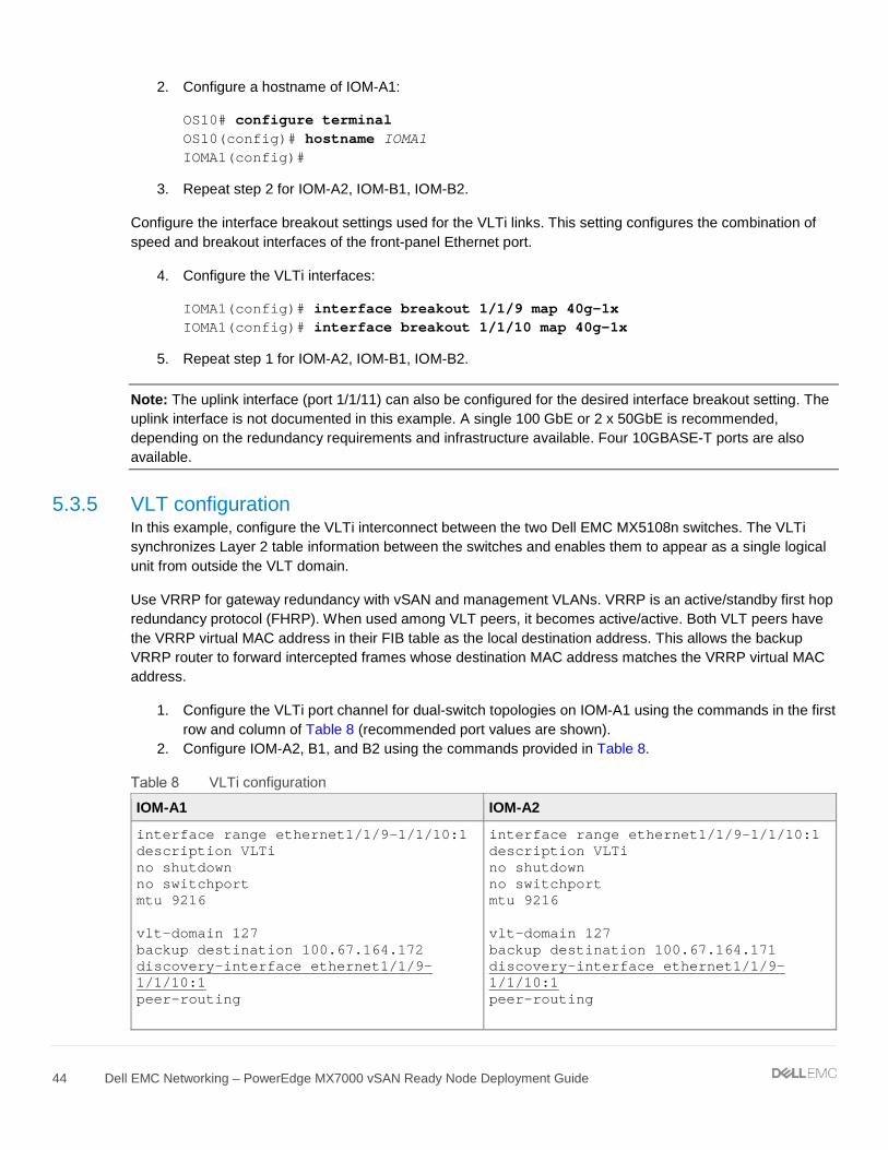
1. Configure the VLTi port channel for dual-switch topologies on IOM-A1 using the commands in the first row and column of Table 8 (recommended port values are shown).
2. Configure IOM-A2, B1, and B2 using the commands provided in Table 8.
VLTi configuration
IOM-A1 IOM-A2
interface range ethernet1/1/9-1/1/10:1 description VLTi no shutdown no switchport mtu 9216 vlt-domain 127 backup destination 100.67.164.172 discovery-interface ethernet1/1/9-1/1/10:1 peer-routing
interface range ethernet1/1/9-1/1/10:1 description VLTi no shutdown no switchport mtu 9216 vlt-domain 127 backup destination 100.67.164.171 discovery-interface ethernet1/1/9-1/1/10:1 peer-routing

45 Dell EMC Networking – PowerEdge MX7000 vSAN Ready Node Deployment Guide
IOM-B1 IOM-B2
interface range ethernet1/1/9-1/1/10:1 description VLTi no shutdown no switchport mtu 9216 vlt-domain 127 backup destination 100.67.164.172 discovery-interface ethernet1/1/9-1/1/10:1
interface range ethernet1/1/9-1/1/10:1 description VLTi no shutdown no switchport mtu 9216 vlt-domain 127 backup destination 100.67.164.171 discovery-interface ethernet1/1/9-1/1/10:1
Note: When implementing Layer 3 routing on the IOM-A1 and A2 switches (not shown), use the command peer-routing within the vlt-domain configuration.
5.3.6 VLAN configuration Configure the VLAN interfaces and Virtual Router Redundancy Protocol (VRRP). VRRP is used as a secondary form of redundancy.
VLAN configuration
IOM-A1 IOM-A2
interface vlan2030 description ESXimanagement no shutdown mtu 9216 ip address 172.20.30.251/24 vrrp-group 30 virtual-address 172.20.30.253 interface vlan2031 description vMotion no shutdown mtu 9216 ip address 172.20.31.251/24 vrrp-group 31 virtual-address 172.20.31.253
interface vlan2030 description ESXimanagement no shutdown mtu 9216 ip address 172.20.30.252/24 vrrp-group 30 virtual-address 172.20.30.253 interface vlan2031 description vMotion no shutdown mtu 9216 ip address 172.20.31.252/24 vrrp-group 31 virtual-address 172.20.31.253
IOM-B1 IOM-B2
interface vlan2032 description vSAN no shutdown mtu 9216 ip address 172.20.32.251/24 vrrp-group 32 virtual-address 172.20.32.253
interface vlan2032 description vSAN no shutdown mtu 9216 ip address 172.20.32.252/24 vrrp-group 32 virtual-address 172.20.32.253

46 Dell EMC Networking – PowerEdge MX7000 vSAN Ready Node Deployment Guide
5.3.7 Node-facing configuration Configure the vSAN node-facing interfaces with the following steps.
Node-facing configuration
IOM-A1 IOM-A2
interface ethernet1/1/1 description "vSAN node 1 Port 1" no shutdown switchport mode trunk switchport access vlan 2030 switchport trunk allowed vlan 2031 mtu 9216 spanning-tree port type edge interface ethernet1/1/2 description "vSAN node 2 Port 1” no shutdown switchport mode trunk switchport access vlan 2030 switchport trunk allowed vlan 2031 mtu 9216 spanning-tree port type edge interface ethernet1/1/5 description "vSAN node 5 Port 1” no shutdown switchport mode trunk switchport access vlan 2030 switchport trunk allowed vlan 2031 mtu 9216 spanning-tree port type edge interface ethernet1/1/6 description "vSAN node 6 Port 1” no shutdown switchport mode trunk switchport access vlan 2030 switchport trunk allowed vlan 2031 mtu 9216 spanning-tree port type edge
interface ethernet1/1/1 description "vSAN node 1 Port 2” no shutdown switchport mode trunk switchport access vlan 2030 switchport trunk allowed vlan 2031 mtu 9216 spanning-tree port type edge interface ethernet1/1/2 description "vSAN node 2 Port 2” no shutdown switchport mode trunk switchport access vlan 2030 switchport trunk allowed vlan 2031 mtu 9216 spanning-tree port type edge interface ethernet1/1/5 description "vSAN node 5 Port 2” no shutdown switchport mode trunk switchport access vlan 2030 switchport trunk allowed vlan 2031 mtu 9216 spanning-tree port type edge interface ethernet1/1/6 description "vSAN node 6 Port 2” no shutdown switchport mode trunk switchport access vlan 2030 switchport trunk allowed vlan 2031 mtu 9216 spanning-tree port type edge
IOM-B1 IOM-B2
interface ethernet1/1/1 description "vSAN node 1 Port 1" no shutdown switchport mode trunk switchport access vlan 1 switchport trunk allowed vlan 2032 mtu 9216 spanning-tree port type edge interface ethernet1/1/2 description "vSAN node 2 Port 1” no shutdown switchport mode trunk
interface ethernet1/1/1 description "vSAN node 1 Port 2” no shutdown switchport mode trunk switchport access vlan 1 switchport trunk allowed vlan 2032 mtu 9216 spanning-tree port type edge interface ethernet1/1/2 description "vSAN node 2 Port 2” no shutdown switchport mode trunk

47 Dell EMC Networking – PowerEdge MX7000 vSAN Ready Node Deployment Guide
switchport access vlan 1 switchport trunk allowed vlan 2032 mtu 9216 spanning-tree port type edge interface ethernet1/1/5 description "vSAN node 5 Port 1” no shutdown switchport mode trunk switchport access vlan 1 switchport trunk allowed vlan 2032 mtu 9216 spanning-tree port type edge interface ethernet1/1/6 description "vSAN node 6 Port 1” no shutdown switchport mode trunk switchport access vlan 1 switchport trunk allowed vlan 2032 mtu 9216 spanning-tree port type edge
switchport access vlan 1 switchport trunk allowed vlan 2032 mtu 9216 spanning-tree port type edge interface ethernet1/1/5 description "vSAN node 5 Port 2” no shutdown switchport mode trunk switchport access vlan 1 switchport trunk allowed vlan 2032 mtu 9216 spanning-tree port type edge interface ethernet1/1/6 description "vSAN node 6 Port 2” no shutdown switchport mode trunk switchport access vlan 1 switchport trunk allowed vlan 2032 mtu 9216 spanning-tree port type edge
Note: The servers in this example are placed in slots 1, 2, 5, and 6. The interface port numbers will vary depending on server location.
5.3.8 Switch pair uplinks The purpose of this example is to show the deployment of a vSAN cluster using two VLT peer switches within a single chassis solution. Administrators can also use this switch pair in a Layer 3 or Layer 2 leaf-spine network topology. For large deployments that require scale, the Layer 3 leaf-spine architecture is commonly used. For detailed information on the Layer 3 design for leaf-spine using Dell EMC Networking OS10, see Dell EMC Networking Layer 3 Leaf-Spine Deployment and Best Practices with OS10.
Features configured on a Layer 3 leaf-spine that are not covered in this document:
• Routing protocols – BGP and OSPF • Equal Cost Multi-Path Routing - ECMP • Uplink Failure Detection- UFD
5.4 VMware vSAN deployment This section contains information on deploying a vSAN cluster to the network. The focus is on vSAN configuration as it pertains to the leaf pair switch configuration in Section 5.2. High level information on server preparation, ESXi, and vCenter will be provided with references for additional support.

48 Dell EMC Networking – PowerEdge MX7000 vSAN Ready Node Deployment Guide
5.4.1 Server setup This section shows how to set up management access to the ESXi hosts.
Follow the steps below to configure the management interface on the ESXi hosts:
1. Access the console through the iDRAC on the server. 2. Log into ESXi. 3. Select Configure Management Network. 4. Select Network Adaptors. 5. Choose vmnic0 Mezzanine 1A.
ESXi Network Adapter setting
6. Select <Enter> OK. 7. Select IPv4 Configuration. 8. Select Set static IPv4 address and network configuration. 9. Enter IPv4 Address 172.20.30.101 10. Enter Subnet Mask 255.255.255.0 11. Enter Default Gateway 172.20.30.253
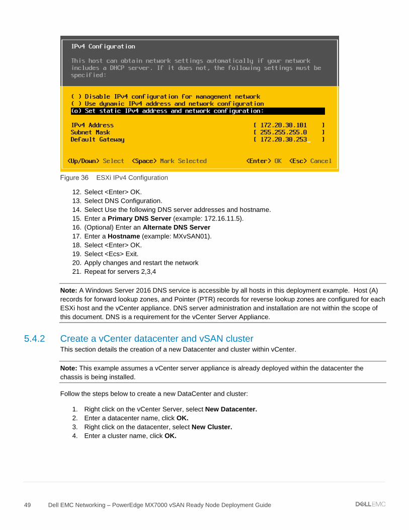
49 Dell EMC Networking – PowerEdge MX7000 vSAN Ready Node Deployment Guide
ESXi IPv4 Configuration
12. Select <Enter> OK. 13. Select DNS Configuration. 14. Select Use the following DNS server addresses and hostname. 15. Enter a Primary DNS Server (example: 172.16.11.5). 16. (Optional) Enter an Alternate DNS Server 17. Enter a Hostname (example: MXvSAN01). 18. Select <Enter> OK. 19. Select <Ecs> Exit. 20. Apply changes and restart the network 21. Repeat for servers 2,3,4
Note: A Windows Server 2016 DNS service is accessible by all hosts in this deployment example. Host (A) records for forward lookup zones, and Pointer (PTR) records for reverse lookup zones are configured for each ESXi host and the vCenter appliance. DNS server administration and installation are not within the scope of this document. DNS is a requirement for the vCenter Server Appliance.
5.4.2 Create a vCenter datacenter and vSAN cluster This section details the creation of a new Datacenter and cluster within vCenter.
Note: This example assumes a vCenter server appliance is already deployed within the datacenter the chassis is being installed.
Follow the steps below to create a new DataCenter and cluster:
1. Right click on the vCenter Server, select New Datacenter. 2. Enter a datacenter name, click OK. 3. Right click on the datacenter, select New Cluster. 4. Enter a cluster name, click OK.

50 Dell EMC Networking – PowerEdge MX7000 vSAN Ready Node Deployment Guide
Create Datacenter and Cluster
5.4.3 Add hosts to vCenter cluster This section details adding hosts to the vSAN cluster.
Follow the steps below to add hosts to the vSAN cluster created in the last section:
1. Right click on the cluster, select Add Host. 2. Enter IP address sled 1, Click NEXT. 3. Enter username and password, click NEXT. 4. Review summary, click NEXT. 5. Assign license, click NEXT. 6. Select desired lockdown mode, keep as disabled for now, click NEXT. 7. Click FINISH. 8. Repeat for sled 2, 5, and 6.
Added hosts to vSAN cluster
Note: vSAN Health issues and Warnings are expected
5.4.4 Configure virtual networking This section provides details on configuring the virtual networking using vCenter.
51 Dell EMC Networking – PowerEdge MX7000 vSAN Ready Node Deployment Guide
Create vDS
1. On the web client Home screen, select Networking. 2. Right click on vSAN Datacenter. Select Distributed switch > New Distributed Switch. 3. Provide a name for the distributed switch (example: vds01-vSAN). Click Next. 4. On the Select version page, select 6.6.0 – ESXi 6.6 and later. Click Next. 5. On the Configure settings page:
a. Leave the Number of uplinks set to 4. b. Leave Network I/O Control set to Enabled. c. Uncheck the Create a default port group box. d. Click Next followed by Finish.
Create vDS
Edit the vDS to use jumbo frames
6. Right click on the vDS, select Settings > Edit Settings. 7. Leave the General settings as default. 8. Select the Advanced page.
a. Change the MTU value to 9000. b. Leave all other settings as default.
9. Click OK.
Add distributed port groups
Value for distributed port groups
Purpose Distributed Port Group Name VLAN
ESXi management Management-vds01-vSAN 2030
vMotion vMotion-vds01-vSAN 2031
vSAN vSAN-vds01-vSAN 2032 The following steps can be used to create the management port group:
1. On the web client Home screen, select Networking. 2. Right click on the distributed switch (vds01-vSAN). Select Distributed Port Group > New
Distributed Port Group.

52 Dell EMC Networking – PowerEdge MX7000 vSAN Ready Node Deployment Guide
3. On the Select name and location page, provide a Name for the distributed port group (example: Management-vds01-vSAN). Click Next.
4. On the Configure settings page, keep all values as default, leaving VLAN type as None. Click Next. 5. Click Finish.
The following steps can be used to create the vMotion and vSAN port groups:
1. On the web client Home screen, select Networking. 2. Right click on the distributed switch (vds01-vSAN). Select Distributed Port Group > New
Distributed Port Group. 3. On the Select name and location page, provide a Name for the distributed port group (example:
vMotion-vds01-vSAN). Click Next. 4. On the Configure settings page, set the VLAN type as VLAN, enter the appropriate VLAN ID
(2031). Click Next. 5. Click Finish. 6. Create the final Distributed Port Group (vSAN) using the value in Table 11.
After creating the distributed port groups (using example values) your configuration would look like Figure 40.
Distributed Port Groups
Configure teaming and failover on management and vMotion port groups:
1. On the web client Home screen, select Networking. 2. Right click on the distributed switch, then select Distributed Port Group > Manage Distributed Port
Groups. 3. Select only the Teaming and failover checkbox, then click Next. 4. Select the management and vMotion port groups. 5. Click Next. 6. On the Teaming and failover page:
a. For Load balancing, select Route based on physical NIC load. b. For Failover order, confirm Uplink 1 and Uplink 2 are both under the Active uplinks section.
Move Uplink 3 and Uplink 4 to Unused uplinks. Leave other settings at their defaults. An example is shown in Figure 41.

53 Dell EMC Networking – PowerEdge MX7000 vSAN Ready Node Deployment Guide
7. Click Next, then Finish to apply the settings.
Teaming and failover settings for distributed port groups
Configure teaming and failover on vSAN port group:
1. On the web client Home screen, select Networking. 2. Right click on the distributed switch, then select Distributed Port Group > Manage Distributed Port
Groups. 3. Select only the Teaming and failover checkbox, then click Next. 4. Select the vSAN port group. 5. Click Next. 6. On the Teaming and failover page:
a. For Load balancing, select Route based on physical NIC load. b. For Failover order, confirm Uplink 3 and Uplink 4 are both under the Active uplinks section.
Move Uplink 1 and Uplink 2 to Unused uplinks. Leave other settings at their defaults. c. Click Next, then Finish to apply the settings.
Add and manage hosts to the vDS:
1. On the web client Home screen, select Networking. 2. Right-click on the distributed switch and select Add and Manage Hosts. 3. On the Select task page, make sure Add hosts is selected, then click Next. 4. On the Select hosts page, click New hosts, then select the check box next to each host in the vSAN
cluster. 5. Click OK, then click Next.
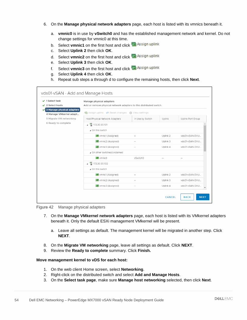
54 Dell EMC Networking – PowerEdge MX7000 vSAN Ready Node Deployment Guide
6. On the Manage physical network adapters page, each host is listed with its vmnics beneath it.
a. vmnic0 is in use by vSwitch0 and has the established management network and kernel. Do not change settings for vmnic0 at this time.
b. Select vmnic1 on the first host and click c. Select Uplink 2 then click OK. d. Select vmnic2 on the first host and click e. Select Uplink 3 then click OK. f. Select vmnic3 on the first host and click g. Select Uplink 4 then click OK. h. Repeat sub steps a through d to configure the remaining hosts, then click Next.
Manage physical adapters
7. On the Manage VMkernel network adapters page, each host is listed with its VMkernel adapters beneath it. Only the default ESXi management VMkernel will be present.
a. Leave all settings as default. The management kernel will be migrated in another step. Click NEXT.
8. On the Migrate VM networking page, leave all settings as default. Click NEXT. 9. Review the Ready to complete summary. Click Finish.
Move management kernel to vDS for each host:
1. On the web client Home screen, select Networking. 2. Right-click on the distributed switch and select Add and Manage Hosts. 3. On the Select task page, make sure Manage host networking selected, then click Next.
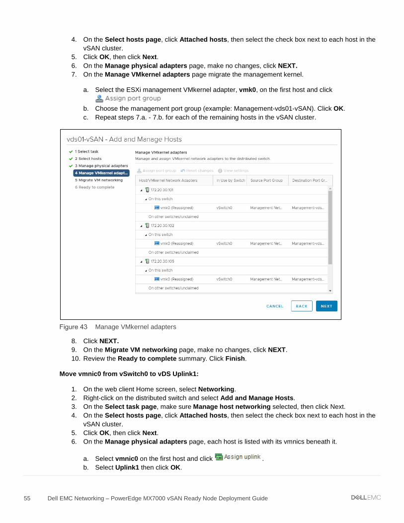
55 Dell EMC Networking – PowerEdge MX7000 vSAN Ready Node Deployment Guide
4. On the Select hosts page, click Attached hosts, then select the check box next to each host in the vSAN cluster.
5. Click OK, then click Next. 6. On the Manage physical adapters page, make no changes, click NEXT. 7. On the Manage VMkernel adapters page migrate the management kernel.
a. Select the ESXi management VMkernel adapter, vmk0, on the first host and click
b. Choose the management port group (example: Management-vds01-vSAN). Click OK. c. Repeat steps 7.a. - 7.b. for each of the remaining hosts in the vSAN cluster.
Manage VMkernel adapters
8. Click NEXT. 9. On the Migrate VM networking page, make no changes, click NEXT. 10. Review the Ready to complete summary. Click Finish.
Move vmnic0 from vSwitch0 to vDS Uplink1:
1. On the web client Home screen, select Networking. 2. Right-click on the distributed switch and select Add and Manage Hosts. 3. On the Select task page, make sure Manage host networking selected, then click Next. 4. On the Select hosts page, click Attached hosts, then select the check box next to each host in the
vSAN cluster. 5. Click OK, then click Next. 6. On the Manage physical adapters page, each host is listed with its vmnics beneath it.
a. Select vmnic0 on the first host and click . b. Select Uplink1 then click OK.

56 Dell EMC Networking – PowerEdge MX7000 vSAN Ready Node Deployment Guide
c. vmnic1,2, and 3 were configured in the previous set of steps and is in their final configuration state. Do not change settings for vmnic1, 2, or 3.
7. Repeat sub steps a through c to configure the remaining hosts, then click Next.
Migrate vmnic0
8. On the Manage VMkernel adapters page, make no changes, click NEXT. 9. On the Migrate VM networking page, make no changes, click NEXT. 10. Review the Ready to complete summary. Click Finish.
Add VMkernels to vSAN port group
1. On the web client Home screen, select Networking. 2. Right-click on the vSAN-vds01-vSAN port group. 3. Select Add VMkernel Adapters. 4. On the Select hosts page, click Attached hosts, then select the check box next to each host in the
vSAN cluster. 5. Click OK, then click Next. 6. On the Configure VMkernel adapter page:
a. Set the MTU to Custom and enter a value of 9000. b. For Available Services, check the vSAN box. c. Click Next.
7. On the IPv4 settings page:
a. Select Use static IPv4 settings. b. Enter in a IPv4 address for each host. (example: 172.20.32.101 255.255.255.0, etc…)

57 Dell EMC Networking – PowerEdge MX7000 vSAN Ready Node Deployment Guide
c. For Gateway, choose Configure on VMkernel adapters, and enter a gateway (example: 172.20.32.253).
d. Click NEXT.
Add vSAN VMkernel
8. Review the Ready to complete summary. Click Finish.
Note: The network configuration examples in this document are designed for flexibility. Most vSAN deployments are Layer 2 and therefore do not require use of gateways on vSAN VMkernel adapters. Use of the gateways and VRRP on the switch configurations will not interfere with operation of Layer 2 deployments. Administrators that require Layer 3 and more advanced vSAN stretched cluster designs can use these example configurations in their deployment.
Add VMkernels to vMotion port group
1. On the web client Home screen, select Networking. 2. Right-click on the vMotion-vds01-vSAN port group 3. Select Add VMkernel Adapters. 4. On the Select hosts page, click Attached hosts, then select the check box next to each host in the
vSAN cluster. 5. Click OK, then click Next. 6. On the Configure VMkernel adapter page:
a. Set the MTU to Custom and enter a value of 9000. b. For Available Services, check the vMotion box c. Click Next.
7. On the IPv4 settings page:
a. Select Use static IPv4 settings. b. Enter in a IPv4 address for each host. (example: 172.20.31.101 255.255.255.0, etc…) c. For Gateway, choose Configure on VMkernel adapters, and enter a gateway (example:
172.20.31.253).

58 Dell EMC Networking – PowerEdge MX7000 vSAN Ready Node Deployment Guide
d. Click NEXT.
Add vMotion VMkernel
8. Review the Ready to complete summary. Click Finish.
Enable and configure vSAN
1. From Hosts and Clusters, click on the vSAN cluster and select the Configure tab
a. Navigate to vSAN > Services.
2. Click opposite the notification vSAN is Turned OFF 3. Choose Single Site cluster, click NEXT. 4. For Services, leave all settings as default, click NEXT. 5. For Claim Disks, change the Group by: to Host
a. Under each host select a disk for the cache tier. b. Under each host select the remaining disks for the capacity tier. If any disks are to be left out of
the vSAN, mark as Do not claim. c. Ensure an equal number of cache and capacity disks are used for each host. The configuration
notification at the bottom should show d. Click NEXT.
6. For fault domains, leave all settings as default, click NEXT. 7. Review the Ready to complete page and click FINISH.
Note: Configuration of fault domains and performance-based settings for vSAN is not within the scope of this document. For further information on completing the vSAN configuration, reference the vSAN administrators guide.

59 Dell EMC Networking – PowerEdge MX7000 vSAN Ready Node Deployment Guide
6 Alternative HW configurations This section summarizes additional hardware options that can be used with this guide with small modifications.
6.1 MX9116n Fabric Switching Engine The MX9116n FSE switch shown in Section 2.2 is a high-performance switch capable of serving as a TOR switch for up to 10 chassis. This switch can be used in either example in this document to increase the bandwidth to external networks. Both the MX5108n and MX9116n use OS10 Enterprise Edition.
Example #1 – Data Center-in-a-box
• Replace the two MX5108n switches with two MX9116n switches • Configuration of global and server facing ports remains unchanged, apart from the interface port
numbering scheme • Configure external network uplinks as desired (not shown) • No change to virtual networking configuration
Example #2 – Chassis in leaf-spine
• Option 1
- Replace the two MX5108n switches in fabric A1/A2 with two MX9116n switches - Keep the two MX5108n switches in fabric B1/B2 if designated vSAN links desired - Configuration of global and server facing ports remains unchanged - Configure external network uplinks as desired (not shown)
• Option 2
- Replace the two MX5108n switches in fabric A1/A2 with two MX9116n switches - Remove the two MX5108n switches from B1/B2 (solution loses dedicated vSAN links) - Configure the MX9116n as shown in example #1 - Configure the virtual networking as shown in example #1 - Configure external network uplinks as desired (not shown)
6.2 MX5016s Storage Sled The MX5016s storage sled can be used on any of the two examples in this document. If there is space in the chassis, additional MX5016s sleds can be utilized.
6.3 MX vSAN Ready Nodes This document uses a MX740c vSAN Ready Node for validation of all network configs. Any MX vSAN Ready Node model can be used in place of the MX740c model with no change in networking deployment steps. Choose the model of MX vSAN Ready Node to fit your compute and storage performance requirements.

Validated components
Dell EMC Choose an item.
A Validated components The following tables include the hardware, software, and firmware used to configure and validate the examples in this document.
Dell EMC PowerEdge MX740c: AF-8-DELLEMC-MX740c
Chassis Information
Qty Item Version
1 PowerEdge MX7000 1.00.01
I/O Modules
Qty Item Version
2 (example #1) 4 (example #2)
Dell EMC Networking MX5108n 10.4.0.E(R3S)
2 (example #1) PowerEdge MX5000s 0.3.8.1
PowerEdge MX740c server details (4qty)
Qty / per server Item Version
2 Intel(R) Xeon(R) Gold 6126 CPU @ 2.60GHz N/A
1 BIOS 1.0.2
1 Storage Controller BOSS-S1 2.6.13.3011
1 Storage Controller HBA330 MMZ 15.17.09.08
2 Network adapter QLogic FastLinQ QL41000 2x25GbE
14.07.07
1 iDRAC 3.20.20.20
1 VMware ESXi 6.5.0
PowerEdge MX5016s Storage Sled (1qty)
Qty Item Version
1 Firmware 2.40
16 HDD/SSD drive slot count N/A
vCenter Server Appliance Information
Qty Item Version
1 vCenter Sever Appliance 6.7.0
Support and feedback
61 Dell EMC Networking – PowerEdge MX7000 vSAN Ready Node Deployment Guide
B Support and feedback Contacting Technical Support
Support Contact Information Web: http://www.dell.com/support
Telephone: USA: 1-800-945-3355
Feedback for this document
We encourage readers to provide feedback on the quality and usefulness of this publication by sending an email to [email protected]
B.1 Related resources Dell EMC Networking Guides
• Dell EMC PowerEdge MX Ethernet Networking Deployment Guide • Dell EMC PowerEdge MX Network Architecture Guide • Dell EMC Networking Layer 3 Leaf-Spine Deployment and Best Practices with OS10
PowerEdge MX7000 manuals and documents
• Dell EMC OpenManage Enterprise-Modular Edition Version 1.00.01 for PowerEdge MX Chassis User's Guide
• Dell EMC PowerEdge MX Getting Started Guide
VMware Validated Design Documentation
Administering VMware vSAN
VMware vSAN Compatibility Guide