Embed Size (px)
Citation preview
37C I V I L e n g I n e e r I n g
http://dx.doi.org/10.1680/cien.2011.164.6.37
The UK olympic Stadium, which will host athletic events and the opening and closing ceremonies of the London 2012 olympic and Paralympic Games, is designed to be converted to a home for British athletics. An innovative use of permanent and temporary forms was developed to meet the 80 000 games capacity and 25 000 legacy capacity, with the final structuring consisting of a permanent sunken concrete bowl and a removable upper seating tier. To save space and drive efficiencies, the majority of spectator facilities were moved outside the structure and the upper seating tier rakes outwards, resulting in the lightest stadium of its size in the world. The rapid delivery of the stadium in just 34 months was achieved through a strategy of prefabrication of concrete and steel elements and just-in-time delivery, supported by a strong collaborative team-working ethic.
Delivering London 2012: the Olympic stadium
Ian CrockfordBEng(Hons), MBA
is project sponsor at the olympic Delivery Authority
Mike Breton MSc, CEng, MICE
is project manager at Sir Robert McAlpine
Fergus McCormickMSc, MA, CEng, MIStructE, MSt
is engineering leader at Buro Happold
Philip Johnson BA, DipArch, Riba
is project architect at Populous
keywordsbuildings, structures & design;
infrastructure planning; olympics
proceedings of IceCivil engineering 164 November 2011
Pages 37–43 Paper 11-00032
The Olympic Stadium is located in the south of the Olympic Park and will be host to athletic events as well as the prestigious opening and closing ceremo-nies of the London 2012 Olympic and Paralympic Games. After the games, the stadium will create a high-class athletics venue for communities within London and beyond and has the capacity to be used for other major legacy sporting uses.
The challenge for the Olympic Delivery Authority (ODA) was to deliver venues and infrastructure that met long-term regeneration ambitions while also deliver-ing intensive short-term needs and unique technical requirements for the games.
Permanent venues were only built where clear legacy needs were identified and sporting and business plans had been developed for their use after the games. This thinking resulted in the brief for an 80 000 capacity stadium in games time that had the flexibility to be converted to a 25 000 capacity venue in legacy.
Brief: a world first
The ODA brief approved by the Olympic Board was composed of two parts
n a stadium of 80 000 capacity for the games
n Flexibility to transform into a smaller capacity venue of 25 000 in legacy.
This proved a real design challenge as converting stadia on this scale was a world first. The designers had to consider the very different requirements for the two modes. The games-time venue was required to use materials and components that could be reused, relocated or recycled to meet ODA’s sustainability objectives whereas the legacy venue was required to be built for durability, low maintenance and low energy costs.
The brief was supplemented by an Olympic venue requirement document that detailed internal room layouts for
Downloaded by [ GEORGIA TECH LIBRARY] on [06/03/17]. Copyright © ICE Publishing, all rights reserved.

38 PRoCeeDINGS oF THe INSTITUTIoN oF CIVIL eNGINeeRS – CIVIL ENGINEERING, 2011, 164, No. Ce6 ISSN 0965 089 X
CRoCKFoRD, BReToN, MCCoRMICK AND JoHNSoN
athletes’ and officials’ accommodation, such as athletic doping control and medical areas, a media centre and steward meeting rooms.
Following the games, the brief was for a 25 000 capacity London athletics venue. The responsibility for seeking a legacy end-user was with the Olympic Park Legacy Company (OPLC) that came into being in 2009. Flexibility of the tem-porary elements was therefore critical to enable OPLC to secure a financially viable legacy business use.
Development of the concept
Team Stadium – a consortium led by Sir Robert McAlpine as main contractor with Buro Happold as engineer, Populous as architect and Hyland Edgar Driver as landscape architect – was appointed in April 2008 as the integrated design and construction team for the London 2012 Olympic Stadium. Development of the concept involved considered responses of all elements of the brief, but appraisal of the site, seating bowl, stadium size and roof were crucial in developing the overall form (Crockford et al., 2011a).
The site within the Olympic Park is bounded by waterways, which effectively create an island site (Figure 1). This posed challenges for the design team in being able to fit the stadium into the site. As such, the final structure is extremely compact and intimate in form, and sub-stantially smaller than past Olympic stadia such as those in Sydney or Beijing.
The single most important decision in the design development was to ‘embrace the temporary’ and remove the majority of spectator facilities from within the struc-ture to locate them in pods on the podium around the stadium. Pulling the facili-ties out of the main body of the stadium enabled a dramatic reduction in the scale and mass of the building as well as the embodied energy of construction with, for example, far fewer heavy concrete con-courses. The solution enabled the stadium to fit on the island site with sufficient cir-culation around it.
The architect developed a seating bowl section for the stadium games and legacy modes consisting of two triangles, with 25 000 permanent seats in a lower tier and 55 000 seats in a demountable upper
tier. The solution offered simplicity and clarity to the process of understanding the conversion. Concrete was utilised as the conventional material for the lower bowl, offering a durable permanent solution.
Early engineering concepts were sketched for a temporary ‘dismantle-able’ upper tier. This led to solutions such as a scaffold-type support to the upper tier and a number of discussions were held with temporary seating suppliers to develop this approach. However, renting tempo-rary solutions for 55 000 seats was found not to be feasible and thus these options had no advantage, in sustainable terms, when compared with a bespoke system.
Scaffold solutions were also inappropri-ate from a structural viewpoint for such a large seating tier and compromised circulation space at podium and ground level. Simple systems offered by a number of temporary suppliers were also inher-ently ill-equipped to deal with an elliptical geometry. A first-principles structural design was therefore the most attractive solution.
The perimeter section and columns of the stadium became steeply inclined, rak-ing upwards, to reduce the footprint and make the structure even more compact, allowing clear circulation around the sta-dium perimeter on the island site. In some circulation pinch-points on the island, extra area was reclaimed using strength-ened earth embankments (Crockford et al., 2011b).
The venue is the most accessible major sports stadium developed with ease of
entry and egress to the venue along with simple access to all facilities. The loca-tion of accessible wheelchair seating and seating for less ambulant spectators is the result of extensive consultation with user groups. It includes innovative use of expandable additional provision if needed, such as during the Paralympic Games.
The team examined carefully the need, if at all, for a roof for such a temporary event venue and the notion of any cover-ing and its size was the subject of much debate. The engineer undertook a study on wind speed at track and field level for the athletes and a three-dimensional virtual wind tunnel was developed to evaluate the wind performance against a number of parameters. The study consid-ered winds exceeding 2 m/s, a level that would invalidate records and create dis-comfort for both athletes and spectators.
The results showed that a partial roof covering was significant in attenuating wind speeds at track level, although the proposed outer fabric wrap was found not to impact the results. A partial roof was therefore chosen with its main purpose being to minimise wind on the track, rather than to shield spectators from rain. The roof’s provenance and design is there-fore a direct result of wind engineering (Crockford et al., 2011b).
Final concepts
The final concept was an innovative lightweight stadium that could be reduced in size through designed-in
Figure 1. Final concept submitted for planning approval, showing the sporting arena on the constrained island site with spectator facilities located in pods outside the main structure
Downloaded by [ GEORGIA TECH LIBRARY] on [06/03/17]. Copyright © ICE Publishing, all rights reserved.
39ISSN 0965 089 X PRoCeeDINGS oF THe INSTITUTIoN oF CIVIL eNGINeeRS – CIVIL ENGINEERING, 2011, 164, No. Ce6
DeLIVeRING LoNDoN 2012: THe oLYMPIC STADIUM
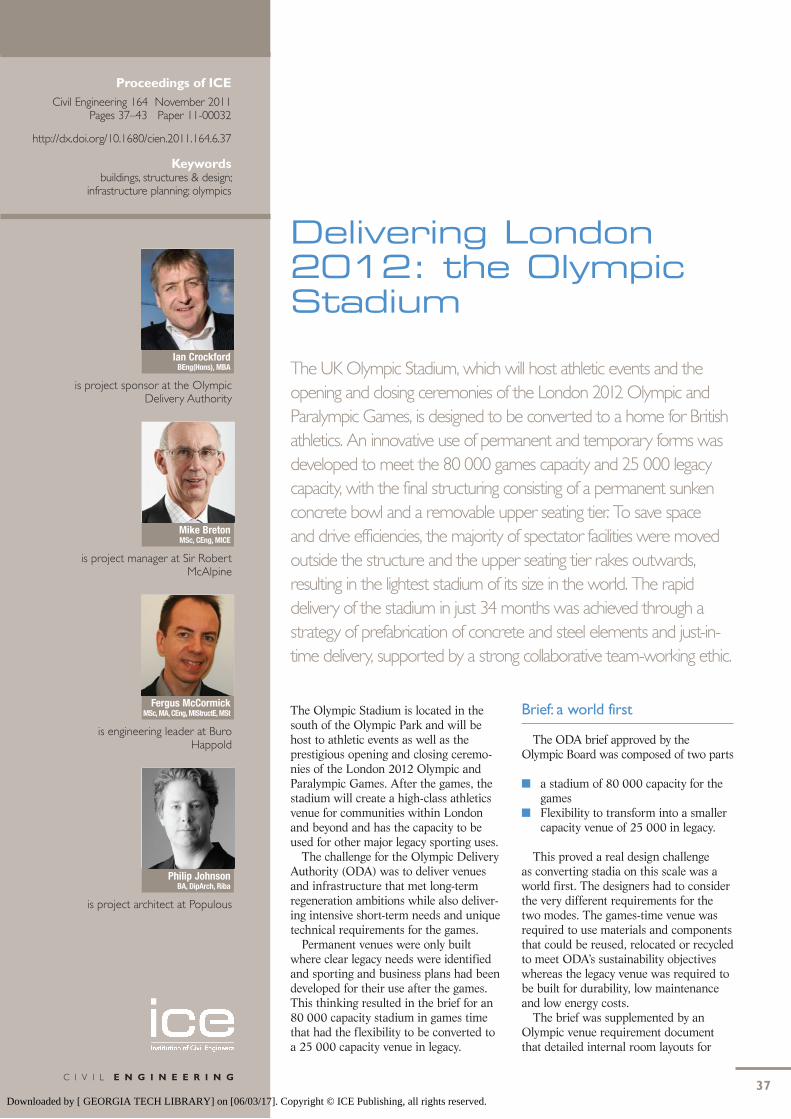
demountability. The design response fitted the challenging brief in an unusual, distinct and elegant way and kept options open for a wide range of legacy uses (Figure 2).
The permanent lower elliptical bowl was sunk into the existing site, with capacity for 25 000 spectators, athletics events as well as an array of other sports uses. It is founded on 5000 piles up to 20 m deep, with a mixture of driven cast in situ piles, continuous flight auger piles and vibro concrete columns. Above is a lightweight temporary, raked, single-tier structure – measuring 315 m long, 256 m wide and 60 m high – to provide the seating needs for the 55 000 additional games-time spectators. All general specta-tor facilities are on podium level.
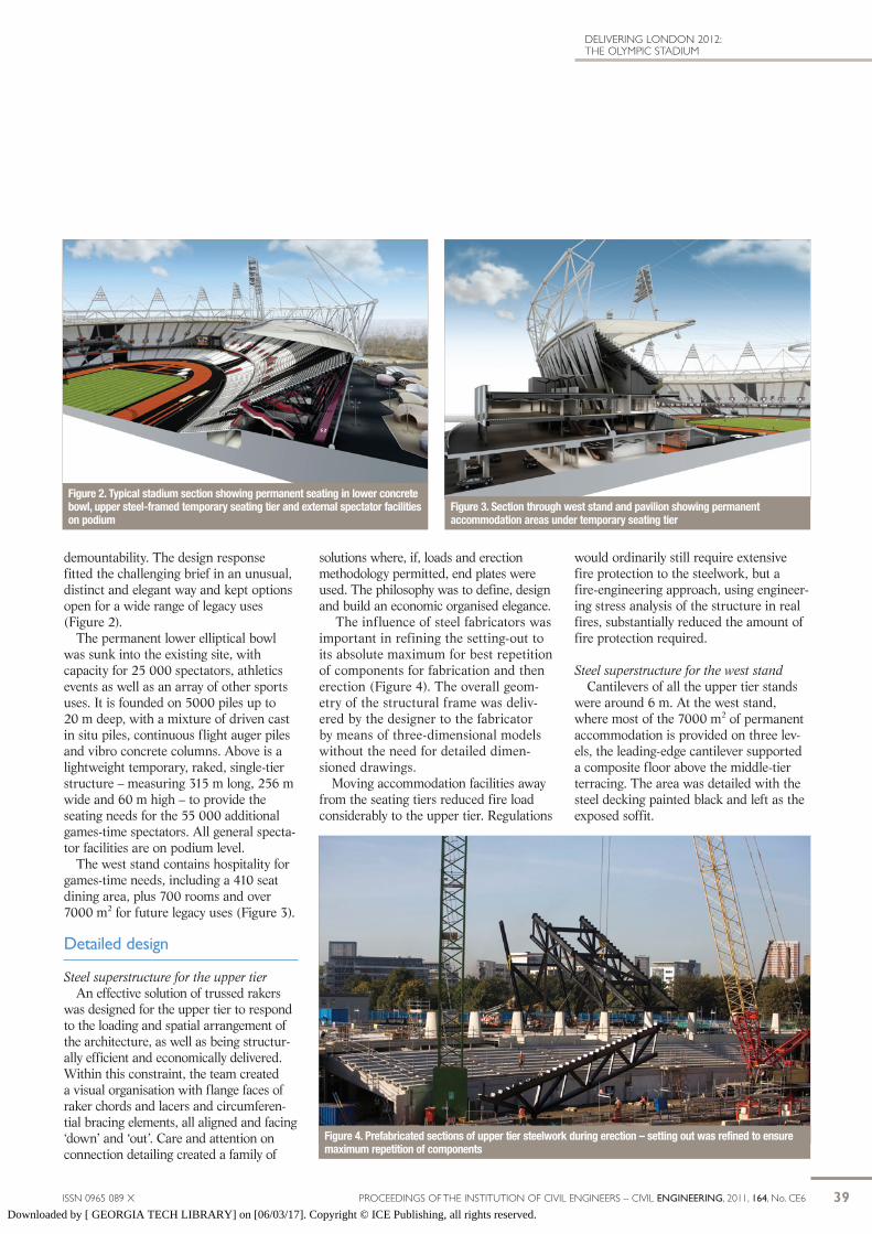
The west stand contains hospitality for games-time needs, including a 410 seat dining area, plus 700 rooms and over 7000 m2 for future legacy uses (Figure 3).
Detailed design
Steel superstructure for the upper tierAn effective solution of trussed rakers
was designed for the upper tier to respond to the loading and spatial arrangement of the architecture, as well as being structur-ally efficient and economically delivered. Within this constraint, the team created a visual organisation with flange faces of raker chords and lacers and circumferen-tial bracing elements, all aligned and facing ‘down’ and ‘out’. Care and attention on connection detailing created a family of
solutions where, if, loads and erection methodology permitted, end plates were used. The philosophy was to define, design and build an economic organised elegance.
The influence of steel fabricators was important in refining the setting-out to its absolute maximum for best repetition of components for fabrication and then erection (Figure 4). The overall geom-etry of the structural frame was deliv-ered by the designer to the fabricator by means of three-dimensional models without the need for detailed dimen-sioned drawings.
Moving accommodation facilities away from the seating tiers reduced fire load considerably to the upper tier. Regulations
would ordinarily still require extensive fire protection to the steelwork, but a fire-engineering approach, using engineer-ing stress analysis of the structure in real fires, substantially reduced the amount of fire protection required.
Steel superstructure for the west standCantilevers of all the upper tier stands
were around 6 m. At the west stand, where most of the 7000 m2 of permanent accommodation is provided on three lev-els, the leading-edge cantilever supported a composite floor above the middle-tier terracing. The area was detailed with the steel decking painted black and left as the exposed soffit.
Figure 3. Section through west stand and pavilion showing permanent accommodation areas under temporary seating tier
Figure 4. Prefabricated sections of upper tier steelwork during erection – setting out was refined to ensure maximum repetition of components
Figure 2. Typical stadium section showing permanent seating in lower concrete bowl, upper steel-framed temporary seating tier and external spectator facilities on podium
Downloaded by [ GEORGIA TECH LIBRARY] on [06/03/17]. Copyright © ICE Publishing, all rights reserved.

40 PRoCeeDINGS oF THe INSTITUTIoN oF CIVIL eNGINeeRS – CIVIL ENGINEERING, 2011, 164, No. Ce6 ISSN 0965 089 X
CRoCKFoRD, BReToN, MCCoRMICK AND JoHNSoN
This is another example where the finish to the building was formed of simple raw engineering components, with care and attention to detailing within a strategic sim-ple architectural colour palette giving an economic, effective and dramatic aesthetic.
Structural dynamic analysisIt is well known that a simple solution
to vertical dynamic issues for grand-stands can be achieved by high-frequency tuning of the structure above around 6 Hz. However, experience with other stadia and other arena indicates that this can be conservative, so a bespoke dynamic analysis of accelerations was undertaken and this enabled significant savings in the steelwork to be achieved.
Figure 5 shows a diagrammatic com-parison between the heavy structural solution required to attain a 6 Hz criteria
and the actual engineered solution with lower frequency justified by detailed acceleration analysis.
Vomitory stairsA series of vomitory stairs carries
spectators to the upper tiers (Figure 6). The stair barriers are formed of glass incorporating a strategy of 56 differ-ent colours from a specially designed palette (McCormack and Knapp, 2010). Lights over the stairs are supported by an elegant arrangement of fine stainless steel suspension cables and rolled steel channels.
Roof designThe structural design of the roof
evolved as a primary cable net to meet the design drivers and also to meet goals of a lightweight, demountable, transform-able roof. The 900 m circumference with 36 m projection roof was designed with the minimal number of elements by employing straight cables with flattish fabric (Figure 7)
Phthalate-free polyvinyl chloride (PVC) was considered as part of the ODA’s PVC reduction policy, however the prod-uct was not sufficiently developed in time for its use on the stadium. PVC fabric was chosen as an economic covering for
a large area and offered an appropriate aesthetic for a temporary summer event. The final design, which was driven by wind engineering, has the effect of cov-ering 68% of spectators in the seating bowl – similar to roof coverings used in the recent Athens and Sydney games.
Compression truss and roof column connections were all bolted for rapid assembly on site and potential future dis-assembly. Bolts were left exposed to view, appropriate for an economic temporary building. Inner circumferential walkways were erected with the main tension ring and integrated services to reduce later high-level building operations.
Arrangements for the opening and closing ceremonies were integrated early into design considerations and the team developed an inner secondary cable net to support the required rigging (Crockford et al., 2011c; McCormick and Birchall, 2011).
Lighting designThe stadium lights were designed to
ensure the best lighting angles for the latest television broadcast requirements. Construction of the fourteen 30 m high, 34 t light units was a significant chal-lenge: it involved an initial lift into the air of the pyramidal lighting unit to allow
Figure 5. Comparison of upper tier structures for a standard 6 Hz performance (top) and with engineering dynamic analysis (bottom)
Figure 7. The 900 m circumference roof consists of PVC fabric supported by a cable net structure – its primary purpose is to reduce wind speeds at track level
Figure 6. Podium concourse under completed upper tier showing vomitory stairs with coloured glass barriers and toilet pods
Downloaded by [ GEORGIA TECH LIBRARY] on [06/03/17]. Copyright © ICE Publishing, all rights reserved.

41ISSN 0965 089 X PRoCeeDINGS oF THe INSTITUTIoN oF CIVIL eNGINeeRS – CIVIL ENGINEERING, 2011, 164, No. Ce6
DeLIVeRING LoNDoN 2012: THe oLYMPIC STADIUM
assembly, to its underneath, of the 12 m long legs and, to its rear, a temporary prop (Figure 8). A double-hook lift was used with a 650 t crane inside the sta-dium to lift and track the whole assem-bly to its correct location 70 m above the field of play. Once all lights were located, permanent stabilising cables were installed and the temporary props removed.
Implementation
The delivery team was engaged under an NEC3 Engineering and Construction Contract (ICE, 2005). Using option C, the sharing mechanism (pain and gain) was negotiated between ODA and the team. Both parties adopted the ethos of the contract, which encourages a collabo-rative, open-book approach to execution of the work.
The contract enabled a large overlap of design and construction, which realised a significant reduction in the overall programme. For example, the major early subcontractors for packages such as concrete (undertaken by Byrne Brothers), precast concrete (undertaken by Tarmac precast terracing) and steelwork (under-taken by Watson Steelwork) were able to be procured at the end of concept design. Working collaboratively with the supply chain enabled the delivery team to control the design development cost risk.
The team’s strategy was to implement a significant amount of prefabrica-tion of concrete and steel elements to protect programme, quality and safety. Achievements included delivering the steelwork geometry wholly through three-dimensional modelling, where information from architect and engineer to contractor was freely shared at an early stage.
Much of the reinforcement for the concrete slabs and columns was formed of prefabricated, welded cages. This allowed just-in-time delivery and rapid assembly on site due to reduced labour time. The early design and procurement plus prefabrication resulted in the stadi-um structure up to the roof compression truss being completed within 14 months of starting on site.
Following selection of a preferred bidder, ODA assessed best-practice
timelines for achieving a concept design and then subsequently going from concept design to start on site. Both these periods are typically 16 or 17 months. The Olympic Stadium concept, however, was developed in just 10 months and the period to start on site was achieved in only 6·5 months. Furthermore, from the start of piling works in May 2008, the project achieved contract completion ahead of the June
2011 scheduled date, in March 2011 (Figure 9).
The anticipated final cost is £486 mil-lion (including legacy transformation works).
Sustainability
ODA’s objectives for sustainability were embedded into the stadium pro-curement process (Epstein et al., 2011).
Figure 9. The stadium was completed on schedule and within budget in March 2011 – note prototype ‘wrap’ panels in foreground, west stand pavilion to lower right and initial external pods
Figure 8. The 14 pyramidal light units weighed 34 t each and required a 650 t crane to be hoisted 70 m to roof level
Downloaded by [ GEORGIA TECH LIBRARY] on [06/03/17]. Copyright © ICE Publishing, all rights reserved.

42 PRoCeeDINGS oF THe INSTITUTIoN oF CIVIL eNGINeeRS – CIVIL ENGINEERING, 2011, 164, No. Ce6 ISSN 0965 089 X
CRoCKFoRD, BReToN, MCCoRMICK AND JoHNSoN
Reduced embodied carbon dioxideCarbon dioxide content embraces both
the in-use carbon dioxide emissions of the stadium released during the operational lifetime of the building and the embodied carbon dioxide content in its construction. In a stadium for which much of the build-ing above podium level had a potential short lifespan – covering warm-up events and 5 weeks of the games – it is the embodied carbon dioxide that is the most significant part. However, the delivery team challenged both parts of the carbon dioxide emissions equation.
The stadium contains 10 700 t of steel, which is approximately one quar-ter of that used in the Beijing stadium, illustrating the reduced carbon dioxide of the London 2012 stadium design (Figure 10). Large-diameter tubes for the roof were reused material from a gas pipeline project.
By far the most significant decisions influencing embodied carbon dioxide are those associated with the designer’s acknowledgement to ‘embrace the tem-porary’, enabling a compact design and lightweight construction throughout. The requirement for temporary seating drove lightweight middle and upper sections of the stadium structure through efficient use of materials and optimisation of the design.
ODA and the delivery team carefully interrogated the required roof coverage and optimised a lightweight, low-car-bon-dioxide solution having a minimum area to respond to wind-engineering issues. Dynamic studies enabled sig-nificant carbon dioxide savings for the bespoke design compared with a design adopting default criteria recommended by standard industry guidance.
Embodied carbon dioxide was also reduced through using low-carbon-diox-ide concrete. The average percentage of cement substitutions (pulverised-fuel ash and ground granulated blast-furnace slag) was raised to 32% from the UK average of 18%. ODA set targets of 25% average recycled aggregate for the games – the stadium podium topping exceeded this with 100% coarse aggre-gate replacement.
A number of key performance indi-cators were developed to consider the carbon dioxide savings achieved – total carbon dioxide mass, carbon dioxide
mass per seat, carbon dioxide mass per unit floor area and carbon dioxide mass per unit roof area. These were consid-ered to monitor internal design develop-ment and progress through the project and also to allow benchmarking in rela-tion to other venues and other Olympic stadia (ODA, 2009; Sheard, 2010).
Energy and water efficiency
For the stadium, ODA specified a 15% improvement on the standard 2006 Building Regulations part L requirements and a 40% reduction in water consumption. This was applied to the legacy portion of the stadium, which was mostly the accommodation in the west stand, providing 7000 m2 of athletes’ and officials’ accommodation. This was achieved by careful design and utilising the power and heat from the Olympic Park’s infrastructure while generating cooling on site.
Biodiversity and green edgesEarly concepts for the stadium con-
sidered the legacy mode as a stadium within the park and strove to maximise the natural potential for soft landscap-ing around the island site. Furthermore, there was a desire to try and deliver this into the construction process early, as a significant part of the project, to
give trees and other vegetation time to mature and bed-in before the games.
A major part of the project concerned the design of new river edges to the east of the stadium. New land was required to provide sufficient circulation in games mode and also to allow high load-ings from construction traffic for the erection and assembly of the stadium. Strengthened soft earth embankments were conceived instead of hard-engi-neered structural embankment edges as part of the aspiration to make London 2012 a ‘green’ games with continuous pathways for biodiversity (Figure 11).
The engineers developed the strength-ened embankments as reinforced earth walls. The number of geometric and topographic constraints combined to create a challenge to this realisation. Additionally, the system included some low-level, embedded-pile-supported load-transfer systems to limit changes to loading of the existing river walls.
Legacy transformation and use
The method in which the roof and upper tiers are planned to be dismantled is the direct opposite sequence in which they were erected. All upper-tier ter-racing can be removed, leaving a series of columns on podium level that will
Outline ofLondon stadium
Outline ofBejing stadium
Figure 10. London 2012 stadium section (blue) overlaid on the Beijing 2004 stadium (red) – the latter used four times more steel than the London stadium
Downloaded by [ GEORGIA TECH LIBRARY] on [06/03/17]. Copyright © ICE Publishing, all rights reserved.

43ISSN 0965 089 X PRoCeeDINGS oF THe INSTITUTIoN oF CIVIL eNGINeeRS – CIVIL ENGINEERING, 2011, 164, No. Ce6
DeLIVeRING LoNDoN 2012: THe oLYMPIC STADIUM
take a roof structure appropriate for a 25 000 capacity legacy athletic stadium. Spectator facilities suitable for the lega-cy use would then also have to be added on the podium level.
In 2010, the UK government appoint-ed OPLC to reconsider all aspects of the Olympic venues after the games. This resulted in the stadium site and building being offered to bidders, allowing recon-sideration of the original legacy plan for the stadium to be reduced to a 25 000 venue for the home of British athletics.
The consortium of West Ham United FC and the London Borough of Newham were chosen as the preferred bidder for the legacy use of the Olympic Stadium. The West Ham bid is founded on the cre-ation of a multi-use venue at the heart of the community with many stakeholders. The aspirations of the long-term legacy of a living stadium thus look like being ful-filled without the need for any significant reduction in capacity.
acknowledgements
The authors acknowledge the contri-butions of Paul Westbury, Philip John-son, Paul Hulme and John Hyland to the preparation of this paper and Adam Wilson for photography. Key members of the project team were as follows.
n Olympic Delivery Authority (client)n CLM (delivery partner/project
manager)n Olympic Park Legacy Company,
Lea Valley Regional Park Authority, London Boroughs of Hackney, Newham, Tower Hamlets and Waltham Forest, London Development Agency (land ownership), Sport England, UK Athletics (stakeholders)
n Team Stadium (integrated design and construction team) formed of Sir Robert McAlpine (main contractor), Populous (architect), Buro Happold (structural, civil, fabric membrane, building services, fire, wind, sustainability, inclusive design, security, acoustics and engineering) and Hyland Edgar Driver (landscape architect)
n Keltbray (groundwork), Keller (piling), Byrne Brothers (in situ and precast concrete), Tarmac (pre-cast concrete), Seele (roof fabric membrane supplier), Bridon Cables (cable supplier), Fagioli Ltd (strand jacking), BMT (wind tunnel testing), McGrath and Lee Warren (bowl steelwork), (Tensar) earth reinforcement, Careys (topping), CMF (steel stairs), Watson Steel Limited (steelwork subcontractor).
What do you think?If you would like to comment on this paper, please email up to 200 words to the editor at [email protected].
If you would like to write a paper of 2000 to 3500 words about your own experience in this or any related area of civil engineering, the editor will be happy to provide any help or advice you need.
referencesCrockford I, et al. (2011a) The London 2012 Olympic
Stadium: Part 1: Concept and philosophy. Proceedings of the 35th International Symposium on Bridge and Struc-ture Engineering, London. IaBSE/IaSS, London, UK.
Crockford I, et al. (2011b) The London 2012 Olympic Stadium: Part 2: The detailed design and construc-tion of the seating bowl and civil works. Proceedings of the 35th International Symposium on Bridge and Struc-ture Engineering, London. IaBSE/IaSS, London, UK
Crockford I, et al. (2011c) The London 2012 Olympic Stadium: Part 3: The detailed design and construc-tion of the roof. Proceedings of the 35th International Symposium on Bridge and Structure Engineering, London. IaBSE/IaSS, London, UK
Epstein D, Jackson R and Braithwaite P (2011) Delivering London 2012: sustainability strategy. Proceedings of the Institution of Civil Engineers – Civil Engineering 164(5): 27–33, http://dx.doi.org/10.1680/cien.2011.164.5.27.
ICE (Institution of Civil Engineers)(2005) NEC3 Engi-neering and Construction Contract Option C. Thomas Telford, London, UK.
mcCormick F and Birchall m (2011) Large fabric cov-erings for arenas and stadia and structure–wind interactions. Proceedings of Tens-Mvd, IV Latin American Symposium of Tensile Structures, Montevideo, Uruguay.
ODa (Olympic Delivery authority) (2009) Towards a One Planet 2012. http://www.london2012.com/making-it-happen/sustainability/index.php (accessed 29/07/2011).
Sheard R (2010) a Different Kind of Olympic Stadium. www.bbc.co.uk/news/uk-11418422 (accessed 12/08/2011).
Figure 11. Strengthened earth embankments provide soft green edges around the stadium
Downloaded by [ GEORGIA TECH LIBRARY] on [06/03/17]. Copyright © ICE Publishing, all rights reserved.