Embed Size (px)
Citation preview

Project funded by the European Commission within the Seventh Framework Programme (2007 – 2013)
Collaborative Project
LOD2 – Creating Knowledge out of Interlinked Data
Deliverable 6.1.3
Final Release of Integrated LOD2 Stack
UI Components Dissemination Level Public
Due Date of Deliverable M48, 31/08/2014
Actual Submission Date M48, 31/08/2014
Work Package WP6, Interface, Component Integration and LOD2 Stack
Task T6.1
Type Prototype
Approval Status Approved
Version 1.0
Number of Pages 53
Filename D6.1.3_final.doc|pdf
Abstract: This report presents the UI software components being contributed to the LOD2 stack. These components either support the integration between components or are UI widgets, which offer the necessary functionality for a targeted domain.
The information in this document reflects only the author’s views and the European Community is not liable for any
use that may be made of the information contained therein. The information in this document is provided “as is”
without guarantee or warranty of any kind, express or implied, including but not limited to the fitness of the
information for a particular purpose. The user thereof uses the information at his/ her sole risk and liabilit y.
Project Number: 257943 Start Date of Project: 01/09/2010 Duration: 48 months

D6.1.3: v1.0
Page 2
History
Version Date Reason Revised by
1.0 10 aug 2014 Ready to review TenForce, et al
1.1 25 aug 2014 Internal review ULEI
1.2 31 aug 2014 Final version TenForce
Author List
Organisation Name Contact Information
TenForce Bert Van Nuffelen [email protected]
ULEI Michael Martin [email protected]
DERI Stephane Campinas [email protected]
ULEI Sebastian Tramp [email protected]
Tenforce Aad Versteden [email protected]
Tenforce Niels Vandekeybus [email protected]
Tenforce Paul Massey [email protected]
ULEI Sandro Athaide Coelho [email protected]
IMP Uros Milosevic [email protected]
ULEI Lorenz Bühmann [email protected]
I2G Tomas Knap [email protected]
D6.1.3: v1.0
Page 3
Executive Summary
The LOD2 stack is a collection of components that support the Linked Data Publishing cycle. To ease the installation and setup of those components on Linux (Debian/Ubuntu) systems, they are distributed through the LOD2 stack Debian package repository.
In this deliverable, making Linked Data accessible via an Interface is described. This extends the work of improving access to Linked Data components. The work in Task 6.1 is targeted at the User Interfaces required to access those components, but in this Deliverable, user interface is taken in a broader context. Extensions to the web-based UI applications are outlines and a new example application is described (which has changed together other components).

D6.1.3: v1.0
Page 4
Abbreviations and Acronyms
IC Integrity Constraint
LOD Linked Open Data
DGS Data Graph Summary
API Application Programming Interface
UI User Interface
NLP Natural Language Processing
REST Representational state transfer
SPARQL SPARQL Protocol and RDF Query Language
SQL Structured Query Language
RDF Resource Description Framework
RDFa Resource Description Framework in Attributes
GUI Graphical User Interface
CSS Cascading Style Sheets
W3C World Wide Web Consortium
XML Extensible Markup Language
JSON JavaScript Object Notation
URI Uniform Resource Identifier
URL Uniform Resource Locator
Regex Regular expression
D6.1.3: v1.0
Page 5
Table of Contents
1. INTRODUCTION ................................................................................................................... 9
2. LOD2 UI INTEGRATION.................................................................................................... 10
2.1 USER INTERFACES ...................................................................................................... 10
2.2 FORMS OF INTEGRATION .......................................................................................... 10
2.3 LOD2 COMPONENTS ................................................................................................... 12
2.4 WEB-BROWSER WIDGET STATUS ............................................................................ 13
3. AVAILABLE WEB-BROWSER UI APPLICATIONS ....................................................... 14
3.1 ROZETA ......................................................................................................................... 14
3.1.1 Dictionary management.............................................................................. 15
3.1.2 Dictionary editor ........................................................................................ 16
3.1.3 Text annotation & enrichment .................................................................... 18
3.1.4 Document similarity search ........................................................................ 19
3.2 CONTEXT ...................................................................................................................... 21
3.2.1 What is conTEXT? ..................................................................................... 21
3.2.2 How does it work?...................................................................................... 22
3.2.3 Where to find it and Future directions ......................................................... 23
3.3 ORE ................................................................................................................................ 24
3.3.1 Logical Debugging ..................................................................................... 25
3.3.2 Schema Enrichment.................................................................................... 27
3.3.3 Naming Issue Detection and Repair ............................................................ 29
3.3.4 Constraint Based Validation ....................................................................... 31
4. SPARK – AN EXAMPLE APPLICATION ......................................................................... 32
4.1 WHAT IS SPARK? ......................................................................................................... 32
4.2 SPARK'S HIGH-LEVEL ARCHITECTURE ................................................................... 36
4.3 APPLICATION LOGIC WITH LINKED DATA ............................................................ 37
4.3.1 Making the model linked-data aware .......................................................... 38
4.3.2 Coping with language types........................................................................ 39
4.3.3 Synchronizing the model state with the database ........................................ 39
4.4 CONSTRUCTING USER INTERFACES FOR LINKED DATA .................................... 41
4.4.1 Context aware components - Spark............................................................. 41
4.5 FINAL COMMENTS ...................................................................................................... 42
5. REPEATABLE REPORTING USING SPARQL ................................................................ 42

D6.1.3: v1.0
Page 6
5.1 INTRODUCTION ........................................................................................................... 42
5.2 WHAT IS REQUIRED TO START................................................................................. 43
5.3 USING ORG-MODE ....................................................................................................... 43
5.4 USE-CASES.................................................................................................................... 44
5.4.1 UC1: Data QA report creation .................................................................... 44
5.4.2 UC2: Documenting the Mapping Discovery ............................................... 46
5.4.3 What is shown ............................................................................................ 48
5.5 SOME FINAL POINTS ................................................................................................... 50
6. LESSONS LEARNT AND CONCLUSIONS ....................................................................... 52
7. REFERENCES ...................................................................................................................... 53
D6.1.3: v1.0
Page 7
List of Figures
Figure 1: Integration Types ........................................................................................................... 10
Figure 2: Rozeta - Welcome screen............................................................................................... 14
Figure 3: Rozeta - Building a dictionary........................................................................................ 15
Figure 4: Rozeta - Selecting a dictionary....................................................................................... 16
Figure 5: Rozeta - Dictionary editor .............................................................................................. 17
Figure 6: Rozeta - Link discovery (SPARQL/Sindice) .................................................................. 18
Figure 7: Rozeta - Link discovery results ...................................................................................... 18
Figure 8: Rozeta - Text annotation & enrichment .......................................................................... 19
Figure 9: Rozeta - Document similarity search.............................................................................. 20
Figure 10: Rozeta - Document similarity search results ................................................................. 20
Figure 11: conTEXT - Screenshot of the faceted browsing view ................................................... 21
Figure 12: conTEXT - architecture ............................................................................................... 23
Figure 13: conTEXT - Interface Usage ......................................................................................... 24
Figure 14: Ore - Debugging view for OWL ontologies. ................................................................. 26
Figure 15: Ore - Enrichment view for SPARQL knowledge bases. ................................................ 28
Figure 16: Ore - Confidence score explanation in enrichment view for SPARQL knowledge bases.
............................................................................................................................................................ 29
Figure 17: Ore - Naming issue detection and repair view. ............................................................. 30
Figure 18: Ore - Constraint validation view. ................................................................................. 32
Figure 19: Spark - Application Data Flow ..................................................................................... 33
Figure 20: Spark – Location based search interface ....................................................................... 34
Figure 21: Spark – Company Overview ........................................................................................ 35
Figure 22: Spark – Importing Data ................................................................................................ 36
Figure 23: Spark – High-Level connections .................................................................................. 36
Figure 24: Spark – Components and Used Technologies ............................................................... 37
Figure 25: Org-Mode – Sample Gnuplot Results ........................................................................... 46
Figure 26: Org-Mode – outline view ............................................................................................. 48
Figure 27: Org-Mode - Simple example ........................................................................................ 49
Figure 28: Org-Mode - Example Results/Graph ............................................................................ 49
Figure 29: Org-Mode - Exported to Open-Office .......................................................................... 50

D6.1.3: v1.0
Page 8
List of Tables
Table 1 - LOD2 Component Integration Type Summary ............................................................... 12
Table 2: Spark – Backbone.js extensions ...................................................................................... 38
Table 3: Spark – Backend Storage Calls ........................................................................................ 40
Table 4: Spark – extended backend storage calls ........................................................................... 40
D6.1.3: v1.0
Page 9
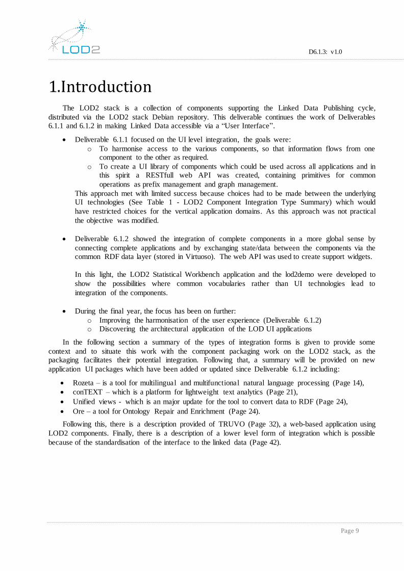
1. Introduction The LOD2 stack is a collection of components supporting the Linked Data Publishing cycle,
distributed via the LOD2 stack Debian repository. This deliverable continues the work of Deliverables 6.1.1 and 6.1.2 in making Linked Data accessible via a “User Interface”.
Deliverable 6.1.1 focused on the UI level integration, the goals were:
o To harmonise access to the various components, so that information flows from one component to the other as required.
o To create a UI library of components which could be used across all applications and in this spirit a RESTfull web API was created, containing primitives for common
operations as prefix management and graph management.
This approach met with limited success because choices had to be made between the underlying UI technologies (See Table 1 - LOD2 Component Integration Type Summary) which would
have restricted choices for the vertical application domains. As this approach was not practical
the objective was modified.
Deliverable 6.1.2 showed the integration of complete components in a more global sense by
connecting complete applications and by exchanging state/data between the components via the common RDF data layer (stored in Virtuoso). The web API was used to create support widgets.
In this light, the LOD2 Statistical Workbench application and the lod2demo were developed to
show the possibilities where common vocabularies rather than UI technologies lead to
integration of the components.
During the final year, the focus has been on further:
o Improving the harmonisation of the user experience (Deliverable 6.1.2) o Discovering the architectural application of the LOD UI applications
In the following section a summary of the types of integration forms is given to provide some
context and to situate this work with the component packaging work on the LOD2 stack, as the packaging facilitates their potential integration. Following that, a summary will be provided on new
application UI packages which have been added or updated since Deliverable 6.1.2 including:
Rozeta – is a tool for multilingual and multifunctional natural language processing (Page 14),
conTEXT – which is a platform for lightweight text analytics (Page 21),
Unified views - which is an major update for the tool to convert data to RDF (Page 24),
Ore – a tool for Ontology Repair and Enrichment (Page 24).
Following this, there is a description provided of TRUVO (Page 32), a web-based application using
LOD2 components. Finally, there is a description of a lower level form of integration which is possible
because of the standardisation of the interface to the linked data (Page 42).

D6.1.3: v1.0
Page 10
2. LOD2 UI integration 2.1 User Interfaces
Although, light web-based applications are the standard these days, there are many other user
interface forms which are still useful - mobile, command-line, native, fat clients, etc. The central questions, as always, remaining:
Who is the intended user? Knowledge engineer1, NLP specialist, Integrator, Data QA, etc.?
What are they expected to do with the interface?
How are they expected to interact (mobile, desktop, etc.)?
Restricting the view of an interface to one type (e.g. GUI) tends to exclude other equally valid
alternative user interfaces. For instance, lack of command line tools often means that frequently performed actions cannot be automated. Although often easier from a development point of view, such
restrictions can become irritating once the user becomes more familiar with the system. So user
interfaces need to be considered from the viewpoint of several different user levels and types (which will take time). These choices also impact on the forms of integration which are possible and the future
integration possibilities.
Whatever level of the user interface, ‘relatively’ consistent needs to be considered, so similar
actions are performed in the same way across the whole user-level interface (but are not dependent on
the tool being user or how the tool is used). Using common vocabularies helps in making the data interfaces more consistent and the data more shareable and reliable.
2.2 Forms of Integration
Typically, applications can be integrated at a number of different levels; database, business logic
and UI [AppInt1, AppInt2]. This is being visualised in the following diagram (which is a variant of that in found in AppInt1), where integration starts at the lowest levels at the database levels and moved
steadily higher with the intention that at the highest levels, all services can be chosen, customised and modified by the interface user:
Figure 1: Integration Types
This shows that as the application integration level moves up (from Integration type 1 to 3), then
individual system components become more disconnected and the need for a more standardised data
exchange format becomes more critical (i.e. common vocabularies become more critical). As described
1 ORE (page 24).
D6.1.3: v1.0
Page 11
in D6.2.3, integration of sets of components together within a vertical domain area (for examples, the Statistical Workbench or the lod2 demo) is shown (Integration type 3, which denotes plugin
architectures). These components are complete applications which are co-ordinated using a specifically
designed framework or meta-application, each component has its own business logic and interface, but they share results via the configured data storages.
In the final integration type (4) the interface becomes a very thin layer, but with the interface
allowing completely different services/tracks to be used (only the signature of the components will need to be compatible and indeed the selection of the component would be via an ontology lookup2). For
example, the means of logging in could be customisable or the interface view would be configurable, the data sources configurable, etc. The biggest challenge then becomes in addressing/defining the
component interfaces, creating a repository of such component descriptions and then
querying/recovering from that repository when a component is requested. The more fine grained the component interfaces the more they can be reused or alternative interfaces can be provided/used to
achieve the same result…
In many ways, a pre-requisite to this work is to have the components available and accessible for integration. The LOD2 stack tackles this deployment problem at two different levels (See D6.2.2 and
D6.1.3):
1. Complete components are packaged and can be automatically installed on a machine, with the packages being able to indicate dependencies and/or make recommendations when required.
2. Java components can be converted into individual Debian binary packages (jar2deb, war2deb), which can then be used within Java based web-applications (maven and similar tools can be
used for the combining and deployment of java libraries).
Component deployment is achieved in the LOD2 stack via the use of Debian packages, which have dependencies expressed allowing components to be integrated at the system level. Such an approach
means it is possible to break up larger systems into smaller individually configurable parts when can
then be recombined, with the packaging system making sure all the required parts are present when deployed. The flipside of this is that the component owners have to work in a specific way and
restructure their code – something which may only be possible once the applications design and quality has reached a sufficient level of maturity.
A further approach for allowing applications to be extended, enhanced and manipulated is via a
plugin like architecture, where the system units are isolated and combined by the user as required (and allowed by the interface between the components). This is in many ways similar to the UNIX/LINUX
system where the shell provides the means to combine the available tools and the tools themselves have
a specific purpose (e.g. sed, awk, cat, wget, etc.).
Additionally, the definition of REST interfaces improves the ease of reusing the services and their
facilities. REST services then provide the role of the UNIX targeted tool (single purpose, good at just
that, focussed, etc.). Likewise, SPARQL end-points, which allow access to RDF data very easily, can very easily be combined with gnuplot for graph plotting [GPLT]. The combining point (UI) could just
as easily be shell level tools, GNU-Emacs/org-mode [GORG], a website or a custom native GUI. The advantages of using smaller, more focussed tools, over the monolithic single interface approach, are
2 In many ways this is similar to reasoning/objectives behind the development of the eTOM and SID models in the telecom area [TM Forum] - it should be possible to replace “components/services” easily based on their signatures and the selection of the component
should be abstracted and flexible enough so that business processes can be easily and dynamically changed.
D6.1.3: v1.0
Page 12
clear and in LOD2 these are supported via the potential of the packaging scheme (which is only a potential because the component owner is still responsible for creating the interface facilities).
The issues described above are not new and are essentially the same as for developing any software
component in a reusable fashion. The issues of software reuse are well known [Reuse1], achieving reuse costs time and effort. In parts this depends on the domain and objectives of the developers/organisation
and the processes they have in place. In LOD2, it is not just reuse of the software, but also the
vocabularies. In the following section the LOD2 components are summarised with a view to the component type and reuse potential (and the types of interface).
2.3 LOD2 Components
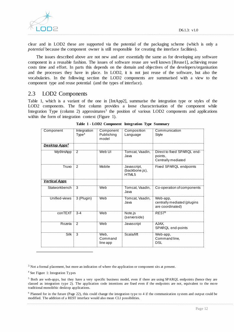
Table 1, which is a variant of the one in [IntApp2], summarise the integration type or styles of the LOD2 components. The first column provides a loose characterisation of the component while
Integration Type (column 2) approximates3 the position of various LOD2 components and applications
within the form of integration context (Figure 1).
Table 1 - LOD2 Component Integration Type Summary
Component Integration Type4
Component Publishing model
Composition Language
Communication Style
Desktop Apps5
Wp9IntApp 2 Web UI Tomcat, Vaadin, Java
Direct to fixed SPARQL end-points, Centrally mediated
Truvo 2 Mobile Javascript, (backbone.js), HTML5
Fixed SPARQL endpoints
Vertical Apps
Statworkbench 3 Web Tomcat, Vaadin, Java
Co-operation of components
Unified-views 3 (Plugin) Web Tomcat, Vaadin, Java
Web-app, centrally mediated (plugins are coordinated)
conTEXT 3-4 Web Note.js (serverside)
REST6
Rozeta 2 Web Javascript AJAX, SPARQL end-points
Silk 3 Web, Command line app
Scala/lift Web-app, Command line, DSL
3 Not a formal placement, but more an indication of where the application or component sits at present.
4 See Figure 1: Integration Types
5 Both are web-apps, but they have a very specific business model, even if there are using SPARQL endpoints (hence they are
classed as integration type 2). The application code intentions are fixed even if the endpoints are not, equivalent to the more
traditional monolithic desktop applications.
6 Planned for in the future (Page 22), this could change the integration type to 4 if the communication system and output could be
modified. The addition of a REST interface would also mean CLI possibilities.

D6.1.3: v1.0
Page 13
Web Services
edcat 3 (Plugin) REST API Tomcat, Spring, Java (DCAT)
Web-app, REST
didicat 3 REST API, Web
Ruby, Rails, emberjs
Web-app, REST
Virtuoso composer
2 Web Web-app, Fixed SPARQL end-point (can allow federated)
Web Maskups
Ontowiki, 3 Web Php/javascript
Lod2demo n/a7 Web Tomcat, Vaadin, Java
Co-operation of components
Widgets
webapi Web Java, tomcat
rdfAuthor 2 Web Javascript
SPARQLed 2 Web Java Web-app, SPARQL end-point
Web portlets and portals
ckan 2 Web Python Centrally mediated,
limes 2 Web
Ore 2 Web Tomcat, Vaadin, Java
2.4 Web-Browser Widget Status
In D6.1.2, SPARQLEd, RDFAuthor, semantic-spatial-browser, CubeViz and Facete were
described. There current status is as follows:
Cubeviz has been updated (part of ontowiki/statistical workbench),
Facete8 has been renamed facate2,
SPARQLEd has been repackaged and is now 0.9.5,
RDFAuthor is still at version 0.9.7, no change.
In D6.1.1, the web API was described as an approach to realize a harmonized interaction with the common data layer at the GUI level. The web API provides a REST interface and, on top of this,
widgets for the Vaadin UI framework widgets were developed. The web API was updated with graph deletion capabilities in D6.2.2 but since then there has been limited progress. The limited progress was
in parts due to lack of further adoption within the LOD2 stack because of its service oriented approach.
The service oriented approach comes with its own dependencies and these put it at odds with the requirements of the developers.
7 Lod2demo is simply a web-app providing a pointer to the other lod2 components and applications.
8 Previously semantic-spatial-browser (semmap), see Deliverable 6.1.2.

D6.1.3: v1.0
Page 14
Since the previous review more emphasis has been placed on improving the available packages to allow reuse and further integration, than on creating new widgets. There are additional services which
have been added (e.g. Rozeta, conText and Ore) as well as many updates and fixes to the vertical
applications (e.g. LOD2 Statistical Workbench and UnifiedViews). In particular the LOD2 Statistical Workbench has integrated a number of new components which are described in D6.2.3. The new
interface for UnifiedViews is also described in D6.1.3.
3. Available Web-Browser UI Applications This section describes the updated domain application UI components, together with the new
components which have been added since D6.1.2 (Year 3).
3.1 Rozeta Rozeta is described in more detail in D3.6.1 and for more details that deliverable should be checked.
This section will focus on the UI aspects only. Rozeta is a multilingual and multifunctional Natural Language Processing (NLP) and Linked Data tool wrapped around STRUTEX. STRUTEX is a structured text knowledge representation technique, which is used to extract words and phrases (from natural language documents) and represent them in a structured form. Its web-based environment provides: automatic extraction of STRUTEX dictionaries in Linked Data form; semantic enrichment through link discovery services; a manual revision and authoring component; a document similarity search tool and an automatic document classifier. The tool aims to be a clean, uncluttered and straightforward user interface for beginners, intermediate and advanced users alike.
The backend store is initially empty and the first time a user starts up Rozeta, they will be taken to the dictionary management module, where the welcome screen will immediately suggest building a dictionary (Figure 2 (1)). Access to the four major modules (i.e. dictionary construction, dictionary management, document similarity search and text annotation / enrichment) is provided in the top right corner (Figure 2 (2)). Additionally, short tips on each of the modules are provided on the right hand side of their respective pages (Figure 2 (3)).
Figure 2: Rozeta - Welcome screen
D6.1.3: v1.0
Page 15
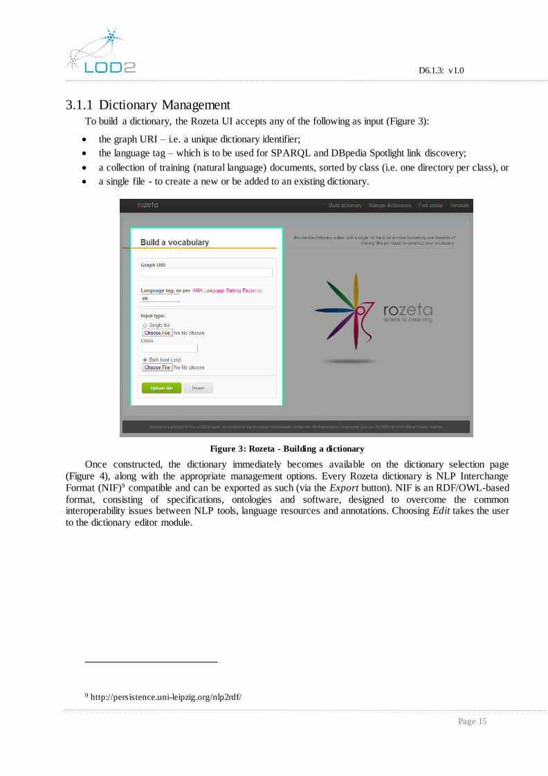
3.1.1 Dictionary Management To build a dictionary, the Rozeta UI accepts any of the following as input (Figure 3):
the graph URI – i.e. a unique dictionary identifier;
the language tag – which is to be used for SPARQL and DBpedia Spotlight link discovery;
a collection of training (natural language) documents, sorted by class (i.e. one directory per class), or
a single file - to create a new or be added to an existing dictionary.
Figure 3: Rozeta - Building a dictionary
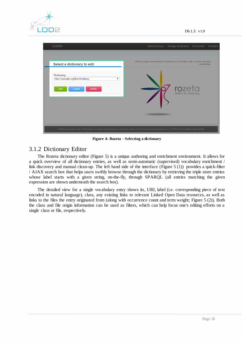
Once constructed, the dictionary immediately becomes available on the dictionary selection page (Figure 4), along with the appropriate management options. Every Rozeta dictionary is NLP Interchange Format (NIF)9 compatible and can be exported as such (via the Export button). NIF is an RDF/OWL-based format, consisting of specifications, ontologies and software, designed to overcome the common interoperability issues between NLP tools, language resources and annotations. Choosing Edit takes the user to the dictionary editor module.
9 http://persistence.uni-leipzig.org/nlp2rdf/
D6.1.3: v1.0
Page 16
Figure 4: Rozeta - Selecting a dictionary
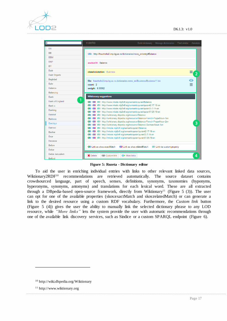
3.1.2 Dictionary Editor The Rozeta dictionary editor (Figure 5) is a unique authoring and enrichment environment. It allows for
a quick overview of all dictionary entries, as well as semi-automatic (supervised) vocabulary enrichment / link discovery and manual clean-up. The left hand side of the interface (Figure 5 (1)) provides a quick-filter / AJAX search box that helps users swiftly browse through the dictionary by retrieving the triple store entries whose label starts with a given string, on-the-fly, through SPARQL (all entries matching the given expression are shown underneath the search box).
The detailed view for a single vocabulary entry shows its, URI, label (i.e. corresponding piece of text encoded in natural language), class, any existing links to relevant Linked Open Data resources, as well as links to the files the entry originated from (along with occurrence count and term weight; Figure 5 (2)). Both the class and file origin information can be used as filters, which can help focus one's editing efforts on a single class or file, respectively.
D6.1.3: v1.0
Page 17
Figure 5: Rozeta - Dictionary editor
To aid the user in enriching individual entries with links to other relevant linked data sources,
Wiktionary2RDF10 recommendations are retrieved automatically. The source dataset contains crowdsourced language, part of speech, senses, definitions, synonyms, taxonomies (hyponyms,
hyperonyms, synonyms, antonyms) and translations for each lexical word. These are all extracted
through a DBpedia-based open-source framework, directly from Wiktionary11 (Figure 5 (3)). The user can opt for one of the available properties (skos:exactMatch and skos:relatedMatch) or can generate a
link to the desired resource using a custom RDF vocabulary. Furthermore, the Custom link button
(Figure 5 (4)) gives the user the ability to manually link the selected dictionary phrase to any LOD resource, while “More links” lets the system provide the user with automatic recommendations through
one of the available link discovery services, such as Sindice or a custom SPARQL endpoint (Figure 6).
10 http://wiki.dbpedia.org/Wiktionary
11 http://www.wiktionary.org
D6.1.3: v1.0
Page 18
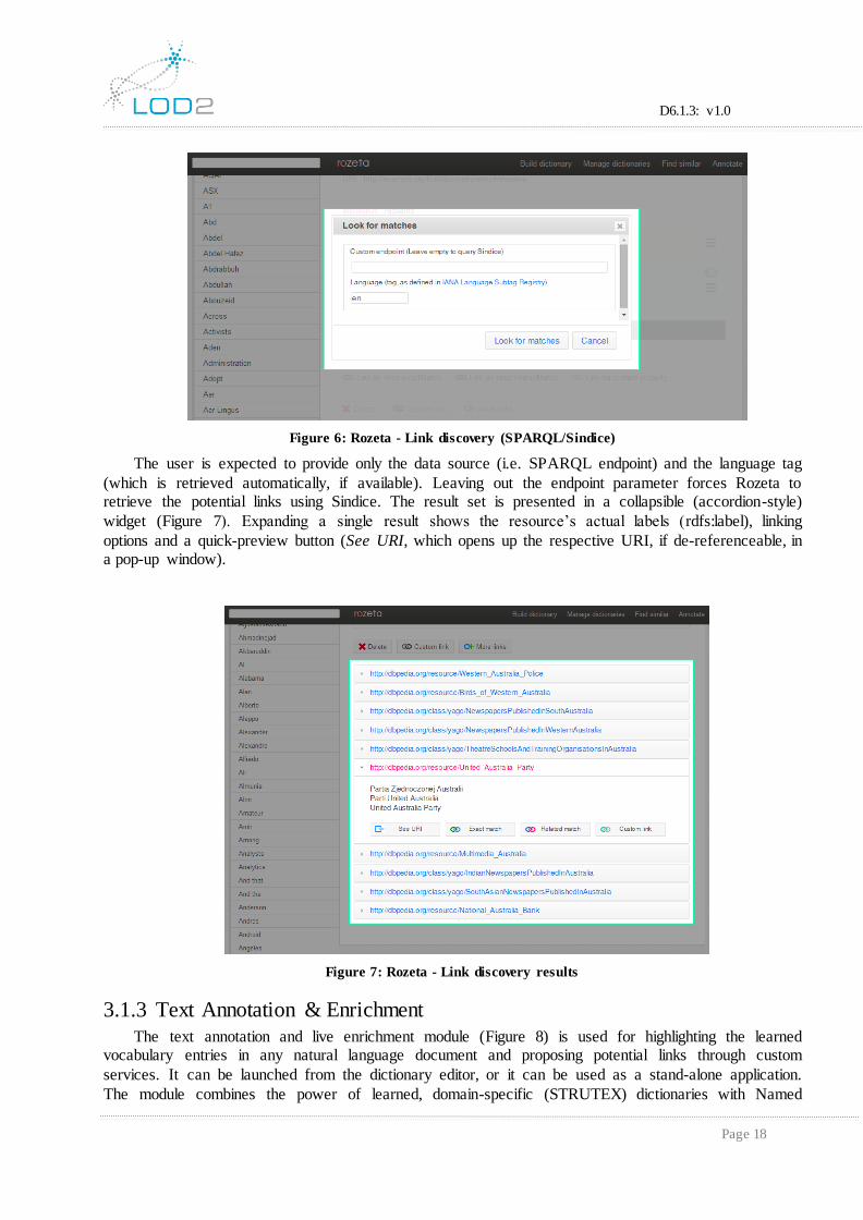
Figure 6: Rozeta - Link discovery (SPARQL/Sindice)
The user is expected to provide only the data source (i.e. SPARQL endpoint) and the language tag
(which is retrieved automatically, if available). Leaving out the endpoint parameter forces Rozeta to retrieve the potential links using Sindice. The result set is presented in a collapsible (accordion-style)
widget (Figure 7). Expanding a single result shows the resource’s actual labels (rdfs:label), linking
options and a quick-preview button (See URI, which opens up the respective URI, if de-referenceable, in a pop-up window).
Figure 7: Rozeta - Link discovery results
3.1.3 Text Annotation & Enrichment
The text annotation and live enrichment module (Figure 8) is used for highlighting the learned vocabulary entries in any natural language document and proposing potential links through custom
services. It can be launched from the dictionary editor, or it can be used as a stand-alone application.
The module combines the power of learned, domain-specific (STRUTEX) dictionaries with Named

D6.1.3: v1.0
Page 19
Entity Recognition (DBpedia Spotlight) and SPARQL-based link discovery mechanisms to highlight the relevant words and phrases in a given piece of text.
The highlighted words and phrases hold links to the corresponding dictionary entry pages, as well
as linking recommendations from DBpedia Spotlight, or custom SPARQL endpoints (retrieved on-the-fly Figure 8 (1); sources are easily managed through an accompanying widget; Figure 8 (2)). The pager
widget (Figure 8 (3)) provides control of the amount of processed text, which can be useful for non-
ASCII encoded languages. The pop-up widget also generates quick-link buttons (skos:exactMatch12 and skos:relatedMatch) for linking the related entries to recommended Linked Open Data resources. Figure
8 shows the live linking recommendation tooltip suggesting multiple potential links for the highlighted entry (Israel) relying on DBpedia Spotlight, as well as Wiktionary2RDF, DBpedia and New York
Times SPARQL endpoints, which were added manually, by the user.
Figure 8: Rozeta - Text annotation & enrichment
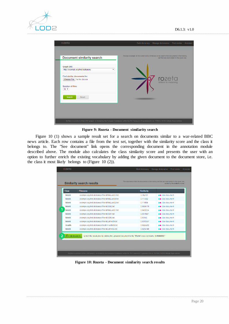
3.1.4 Document Similarity Search
The document similarity search module (Figure 9) calculates the similarity scores between the given document and all other documents in the test set, for a given piece of text and a graph URI that
represents a dictionary/knowledge graph.
12 http://www.w3.org/2004/02/skos/
D6.1.3: v1.0
Page 20
Figure 9: Rozeta - Document similarity search
Figure 10 (1) shows a sample result set for a search on documents similar to a war-related BBC
news article. Each row contains a file from the test set, together with the similarity score and the class it belongs to. The "See document" link opens the corresponding document in the annotation module
described above. The module also calculates the class similarity score and presents the user with an
option to further enrich the existing vocabulary by adding the given document to the document store, i.e. the class it most likely belongs to (Figure 10 (2)).
Figure 10: Rozeta - Document similarity search results
D6.1.3: v1.0
Page 21
3.2 conTEXT
3.2.1 What Is conTEXT?
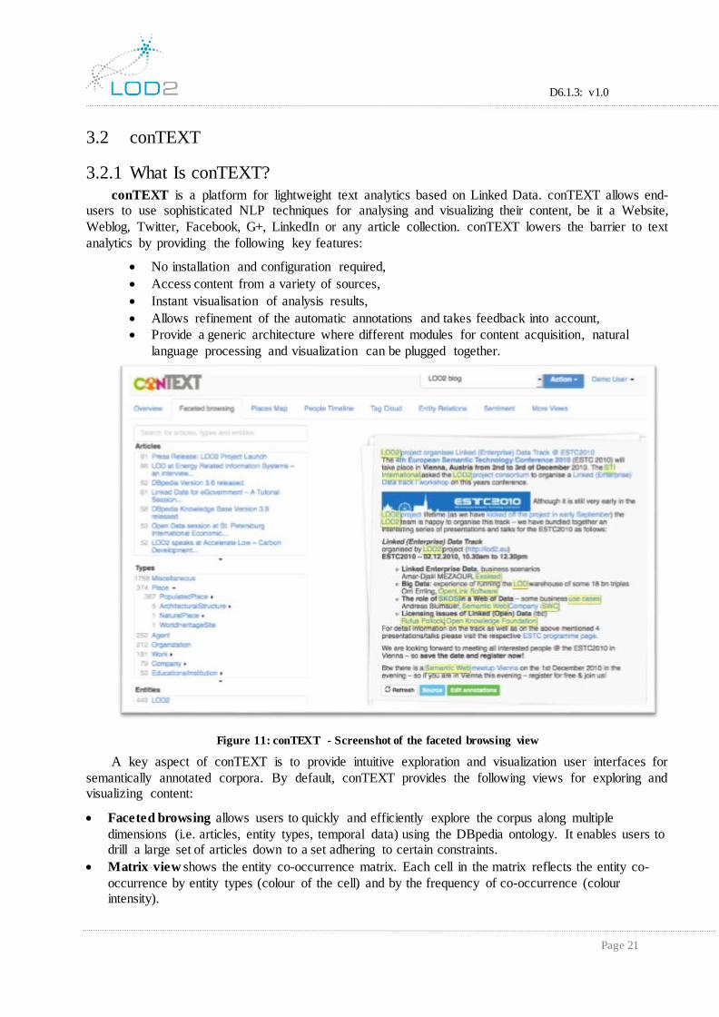
conTEXT is a platform for lightweight text analytics based on Linked Data. conTEXT allows end-users to use sophisticated NLP techniques for analysing and visualizing their content, be it a Website,
Weblog, Twitter, Facebook, G+, LinkedIn or any article collection. conTEXT lowers the barrier to text
analytics by providing the following key features:
No installation and configuration required,
Access content from a variety of sources,
Instant visualisation of analysis results,
Allows refinement of the automatic annotations and takes feedback into account,
Provide a generic architecture where different modules for content acquisition, natural
language processing and visualization can be plugged together.
Figure 11: conTEXT - Screenshot of the faceted browsing view
A key aspect of conTEXT is to provide intuitive exploration and visualization user interfaces for
semantically annotated corpora. By default, conTEXT provides the following views for exploring and visualizing content:
Faceted browsing allows users to quickly and efficiently explore the corpus along multiple
dimensions (i.e. articles, entity types, temporal data) using the DBpedia ontology. It enables users to drill a large set of articles down to a set adhering to certain constraints.
Matrix view shows the entity co-occurrence matrix. Each cell in the matrix reflects the entity co-
occurrence by entity types (colour of the cell) and by the frequency of co-occurrence (colour intensity).

D6.1.3: v1.0
Page 22
Trend view shows the occurrence frequency of entities in the corpus over the times. The trend view
requires a corpus with articles having a timestamp (such as blog posts or tweets).
Image view shows a picture collage created from the entities Wikipedia images. This is an
alternative for tag cloud, which reflects the frequent entities in the corpora by using different image
sizes.
Tag cloud shows entities found in the corpus in different sizes depending on their prevalence. The
tag cloud helps to quickly identify the most prominent entities in the corpora.
Chordal graph view shows the relationships among the different entities in a corpus. The relationships are extracted based on the co-occurrence of the entities and their matching to a set of
predefined natural language patterns.
Places map shows the locations and the corresponding articles in the corpus. This view allows users to quickly identify the spatial distribution of locations referred to in the corpus.
People timeline shows the temporal relations between people mentioned in the corpus. For that
purpose, references to people found in the corpus are enriched with birth and death days found in DBpedia.
3.2.2 How Does It Work?
conTEXT exploits Semantic Web and Linked Data technologies in the following ways:
The linked-data aware Natural Language Interchange format (NIF) is used for integrating various
NLP tools.
Linked Data based disambiguations based on FOX and DBpedia Spotlight work with real-world entities rather than surface forms.
Linked Data background knowledge is used to enrich the result of the analysis and provide upper-
level ontological knowledge for facilitating the exploration.
Semantic annotations are encoded in RDFa and can be re-integrated back into the original data
sources.
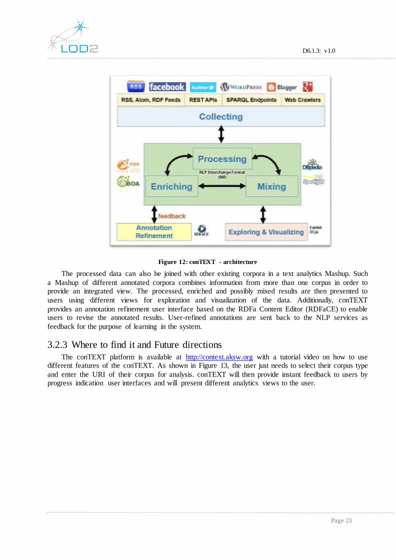
Figure 12, shows the process of text analytics in conTEXT. The process starts by collecting
information from the web or social web. conTEXT utilizes standard information access methods and protocols such as RSS/ATOM feeds, SPARQL endpoints and REST APIs as well as customized
crawlers for SlideWiki, WordPress, Blogger and Twitter to build a corpus of information relevant for a
certain user. The assembled text corpus is then processed by NLP services. While conTEXT can integrate virtually any NLP service, it currently implements interfaces for DBpedia Spotlight and the
Federated knOwledge eXtraction Framework (FOX). The processed corpus is further enriched by two
mechanisms:
1. DBpedia URIs of the found entities are de-referenced in order to add more specific information to
the discovered named entities (e.g. longitude and latitudes for locations, birth and death dates for people etc.).
2. Entity co-occurrences are matched with pre-defined natural-language patterns for DBpedia predicates provided by BOA (BOotstrapping linked datA) in order to extract possible relationships
between the entities.
D6.1.3: v1.0
Page 23
Figure 12: conTEXT - architecture
The processed data can also be joined with other existing corpora in a text analytics Mashup. Such
a Mashup of different annotated corpora combines information from more than one corpus in order to provide an integrated view. The processed, enriched and possibly mixed results are then presented to
users using different views for exploration and visualization of the data. Additionally, conTEXT
provides an annotation refinement user interface based on the RDFa Content Editor (RDFaCE) to enable users to revise the annotated results. User-refined annotations are sent back to the NLP services as
feedback for the purpose of learning in the system.
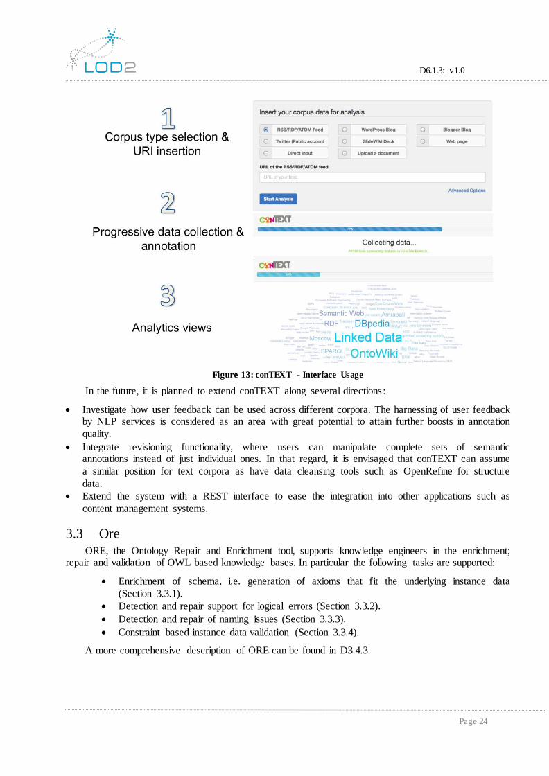
3.2.3 Where to find it and Future directions
The conTEXT platform is available at http://context.aksw.org with a tutorial video on how to use different features of the conTEXT. As shown in Figure 13, the user just needs to select their corpus type
and enter the URI of their corpus for analysis. conTEXT will then provide instant feedback to users by progress indication user interfaces and will present different analytics views to the user.
D6.1.3: v1.0
Page 24
Figure 13: conTEXT - Interface Usage
In the future, it is planned to extend conTEXT along several directions :
Investigate how user feedback can be used across different corpora. The harnessing of user feedback by NLP services is considered as an area with great potential to attain further boosts in annotation
quality.
Integrate revisioning functionality, where users can manipulate complete sets of semantic annotations instead of just individual ones. In that regard, it is envisaged that conTEXT can assume
a similar position for text corpora as have data cleansing tools such as OpenRefine for structure
data.
Extend the system with a REST interface to ease the integration into other applications such as
content management systems.
3.3 Ore
ORE, the Ontology Repair and Enrichment tool, supports knowledge engineers in the enrichment; repair and validation of OWL based knowledge bases. In particular the following tasks are supported:
Enrichment of schema, i.e. generation of axioms that fit the underlying instance data
(Section 3.3.1).
Detection and repair support for logical errors (Section 3.3.2).
Detection and repair of naming issues (Section 3.3.3).
Constraint based instance data validation (Section 3.3.4).
A more comprehensive description of ORE can be found in D3.4.3.

D6.1.3: v1.0
Page 25
3.3.1 Logical Debugging
An increasingly large number of OWL ontologies become available on the Semantic Web and the descriptions in the ontologies become more complicated. While the expressiveness of OWL is indeed a
strong feature, it can also lead to a misunderstanding and misuse of particular types of constructs in the
language. In turn this can lead to modelling errors in the ontology, i.e. inconsistency or unsatisfiable classes.
Inconsistency, in simple terms, is a logical contradiction in the knowledge base, which makes it
impossible to derive any meaningful information by applying standard OWL reasoning techniques.
Unsatisfiable classes are usually a fundamental modelling error, in that they cannot be used to
characterize any individual which in turn means they cannot have an individual.
Both kinds of modelling errors are quite easy to detect by standard OWL reasoners, however,
determining why the errors hold can be a considerable challenge even for experts in the formalism and
in the domain, even for modestly sized ontologies. The problem worsens significantly as the number and complexity of axioms of the ontology grows. Clearly, only with the understanding of why such an
undesired entailment holds, it is possible to get rid of the errors, i.e. to repair the ontology.
In the area of ontology debugging, a specific type of explanation called justifications was introduced by the research community, which is basically a minimal subset of the ontology that is
sufficient for the entailment to hold.
The set of axioms corresponding to the justification is minimal in the sense that if an axiom is removed from the set, the remaining axioms no longer support the entailment. One such justification
could for example be
metal EquivalentTo chemical and (atomic-number some integer) and (atomic-number exactly 1 Thing)
nonmetal EquivalentTo chemical and (atomic-number some integer) and (atomic-number exactly 1 Thing)
metal DisjointWith nonmetal
which gives an explanation for why the class metal is unsatisfiable.
D6.1.3: v1.0
Page 26
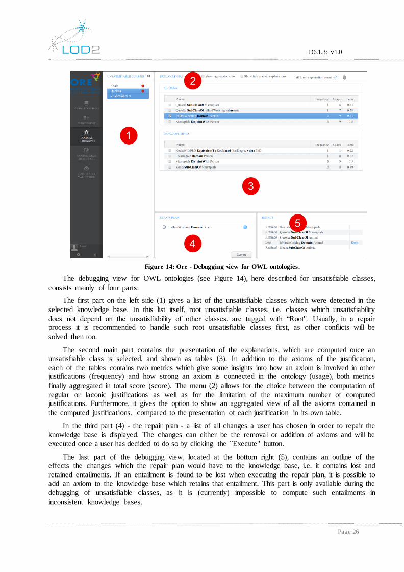
Figure 14: Ore - Debugging view for OWL ontologies.
The debugging view for OWL ontologies (see Figure 14), here described for unsatisfiable classes,
consists mainly of four parts:
The first part on the left side (1) gives a list of the unsatisfiable classes which were detected in the
selected knowledge base. In this list itself, root unsatisfiable classes, i.e. classes which unsatisfiability
does not depend on the unsatisfiability of other classes, are tagged with “Root''. Usually, in a repair process it is recommended to handle such root unsatisfiable classes first, as other conflicts will be
solved then too.
The second main part contains the presentation of the explanations, which are computed once an unsatisfiable class is selected, and shown as tables (3). In addition to the axioms of the justification,
each of the tables contains two metrics which give some insights into how an axiom is involved in other justifications (frequency) and how strong an axiom is connected in the ontology (usage), both metrics
finally aggregated in total score (score). The menu (2) allows for the choice between the computation of
regular or laconic justifications as well as for the limitation of the maximum number of computed justifications. Furthermore, it gives the option to show an aggregated view of all the axioms contained in
the computed justifications, compared to the presentation of each justification in its own table.
In the third part (4) - the repair plan - a list of all changes a user has chosen in order to repair the knowledge base is displayed. The changes can either be the removal or addition of axioms and will be
executed once a user has decided to do so by clicking the `̀ Execute'' button.
The last part of the debugging view, located at the bottom right (5), contains an outline of the effects the changes which the repair plan would have to the knowledge base, i.e. it contains lost and
retained entailments. If an entailment is found to be lost when executing the repair plan, it is possible to add an axiom to the knowledge base which retains that entailment. This part is only available during the
debugging of unsatisfiable classes, as it is (currently) impossible to compute such entailments in
inconsistent knowledge bases.

D6.1.3: v1.0
Page 27
3.3.2 Schema Enrichment
The Semantic Web has recently seen a rise in the availability and usage of knowledge bases, as can be observed within the Linking Open Data Initiative, the TONES and Protégé ontology repositories, or
the Watson search engine. Despite this growth, there is still a lack of knowledge bases that consist of
sophisticated schema information and instance data adhering to this schema. Several knowledge bases, e.g. in the life sciences, only consist of schema information, while others are, to a large extent, a
collection of facts without a clear structure, e.g. information extracted from data bases or texts. The
combination of sophisticated schema and instance data would allow powerful reasoning, consistency checking, and improved querying possibilities. Schema enrichment allows to create a sophisticated
schema base based on existing data (sometimes referred to as `̀ grass roots'' approach or `̀ after the fact'' schema creation).
As an example, consider a knowledge base containing a class Capital and instances of this class,
e.g. London, Paris, Washington, Canberra, etc. A machine learning algorithm could, then,
suggest that the class Capital may be equivalent to one of the following OWL class expressions in
Manchester OWL syntax13:
City and isCapitalOf min 1 GeopoliticalRegion
City and isCapitalOf min 1 Country
Both suggestions could be plausible: The first one is more general and includes cities that are
capitals of states, whereas the latter one is stricter and limits the instances to capitals of countries. A knowledge engineer can decide which one is more appropriate, i.e. a semi-automatic approach is used,
and the machine learning algorithm should guide her by pointing out which one fits the existing
instances better. Assuming the knowledge engineer decides for the latter, an algorithm can show her
whether there are instances of the class Capital which are neither instances of City nor related via the
property isCapitalOf to an instance of Country.14
The knowledge engineer can then continue to look at those instances and assign them to a different class as well as provide more complete information; thus improving the quality of the knowledge base.
After adding the definition of Capital an OWL reasoner can compute further instances of the class which have not been explicitly assigned before.
13 http://www.w3.org/TR/owl2-manchester-syntax/
14 This is not an inconsistency under the standard OWL open world assumption, but rather a hint towards a
potential modelling error.

D6.1.3: v1.0
Page 28
Figure 15: Ore - Enrichment view for SPARQL knowledge bases.
The enrichment view for SPARQL knowledge bases (see Figure 15), can be subdivided into two
main parts:
The first part on the left side (1) allows for configuring the enrichment process and currently
provides the following options:
Resource URI denotes the entity for which schema axioms are generated.
Resource type can be used to define whether the entity is of type class, object property or
data property. Additionally, it's possible to detect the type automatically by getting the type
information from the knowledge base.
Max. execution time is used to set a fixed maximum execution time for the learning
process for each chosen axiom type.
Max. returned axioms limits the number of return axioms per axiom type computed and shown to the user.
Threshold can be used to filter out axiom suggestion that have a confidence score lower
than the chosen value.
Axiom types are used to declare for which types of axioms suggestions are generated.
The second part on the right side (2) shows the generated axiom suggestions as well as their
confidence score for each chosen axiom type in forms of tables. Additionally, it is possible to get some more details about the confidence score by clicking on the question mark symbol (?)

D6.1.3: v1.0
Page 29
Figure 16: Ore - Confidence score explanation in enrichment view for SPARQL knowledge bases.
This shows up a new dialogue as shown in Figure 16. The dialogue gives some natural language
based explanation about the score depending on the axiom type. Moreover, positive and negative examples (if exist) according to the axiom are shown, thus, giving some more detailed insights in how
the axiom fits the data of the knowledge base.
3.3.3 Naming Issue Detection and Repair
During the decades of knowledge engineering research, there has been recurrent dispute on how the
natural language structure influences the structure of formal knowledge bases and vice versa. A large
part of the community seems to recognise that the content expressed in formal representation languages, such as the Semantic Web ones, should be accessible not only to logical reasoning machines but also to
humans and NLP procedures, and thus resemble the natural language as much as possible. It is quite
common in ontologies that a subclass has the same head noun as its parent class.15
By an earlier study it was estimated that in ontologies for technical domains this simple pattern is
verified in 50-80% of class-subclass pairs such that the subclass name is a multi-token one. This number
further increases if one considers thesaurus correspondence (synonymy and hypernymy) rather than literal string equality. In fact, the set-theoretic nature of taxonomic path entails that the correspondence
of head nouns along this path should be close to 100% in principle; the only completely innocent
15 The head noun is typically the last token, but not always, in particular due to possible prepositional constructions, as, e.g., in “HeadOfDepartment''.

D6.1.3: v1.0
Page 30
deviations from it should be those caused by incomplete thesauri. In other words, any violation of head noun correspondence may potentially indicate a (smaller or greater) problem in the ontology.
Prototypical situations are:
Inadequate use of class-subclass relationship, typically in the place of whole-part or class-instance relationship, i.e., a conceptualisation error frequently occurring in novice
ontologies.
Name shorthanding, typically manifested by use of adjective, such as “State-Owned'' (subclass of “Company'').
While the former requires complex refactoring of the ontology fragment, the latter can be healed by
propagation of the parent name down to the child name.
Figure 17: Ore - Naming issue detection and repair view.
Naming issue detection and repair in ORE is supported by the integration of the PatOMat framework16. The whole process is basically done in three succeeding steps, all of them visualized in a
single view shown in Figure 17. Here the user can select a naming pattern in the leftmost list (1).
PatOMat then detects instances of the selected pattern in the currently loaded ontology, e.g., [?OP1 P=Contribution;?OP1 A=Poster] (2). For the selected pattern instances the user will be provided a list of
renaming instructions (3), for example to rename the class Poster to PosterContribution, which can then be used to transform the ontology and solve the detected naming issues.
16 PatOMat framework: http://patomat.vse.cz/
D6.1.3: v1.0
Page 31
3.3.4 Constraint-Based Validation
Integrity constraints provide a mechanism for ensuring that data conforms to guidelines specified by the defined schema. The demand for validating instance data as in relational databases or XML tools
also holds for knowledge modelled in languages of the Semantic Web. In some use cases and for some
requirements, OWL users assume and intend OWL axioms to be interpreted as Integrity Constraints (IC). However, the direct semantics of OWL17 does not interpret OWL axioms in this way; thus, the
consequences that one can draw from such ontologies differ from the ones that some users intuitively
expect and require. In other words, some users want to use OWL as a validation or constraint language for RDF instance data, but that is not possible using OWL based tools that correctly implement the
standard semantics of OWL.
To see the nature of the problem, consider an OWL ontology for a book store and the requirement
to impose the following IC on the data:
Each book must have an ISBN.
This constraint could be interpreted in the following way:
Whenever an instance bookX of Book is added to the ontology, a check should be
performed to verify whether the ISBN of bookX has been specified; if not, the update should be rejected.
Indeed, this constraint can be concisely and unambiguously represented as OWL axiom:
Class: Book
SubClassOf: hasISBN some xsd:string
However, this axiom will not be interpreted as check by tools which implement the standard OWL semantics. In fact, according to the standard OWL semantics, the following is the case:
Having a book without an ISBN in the ontology does not raise an error, but leads to the
inference that the book in question has an unknown ISBN.
In some cases, users want these inferences; but in others, users want integrity constraint violations
to be detected, reported, repaired, etc.
One approach for using OWL as an expressive schema language is to apply an alternative semantics such that OWL axioms can be used as ICs. The idea behind it is to interpret OWL axioms
with Closed World Assumption (CWA) and a weak form of Unique Name Assumption (UNA). Assuming a CWA interpretation basically means that an assertion is false if it's not explicitly known it is
true or false. Weak UNA means that if two individuals are not inferred to be the same, then they will be
assumed to be distinct. Based on these assumptions, translating an OWL axiom into one or more SPARQL queries is suggested to validate the given constraint. This approach is integrated in ORE, thus,
it's possible to define and validate ICs by reusing OWL as language.
17 http://www.w3.org/TR/owl2-d irect-semantics/
D6.1.3: v1.0
Page 32
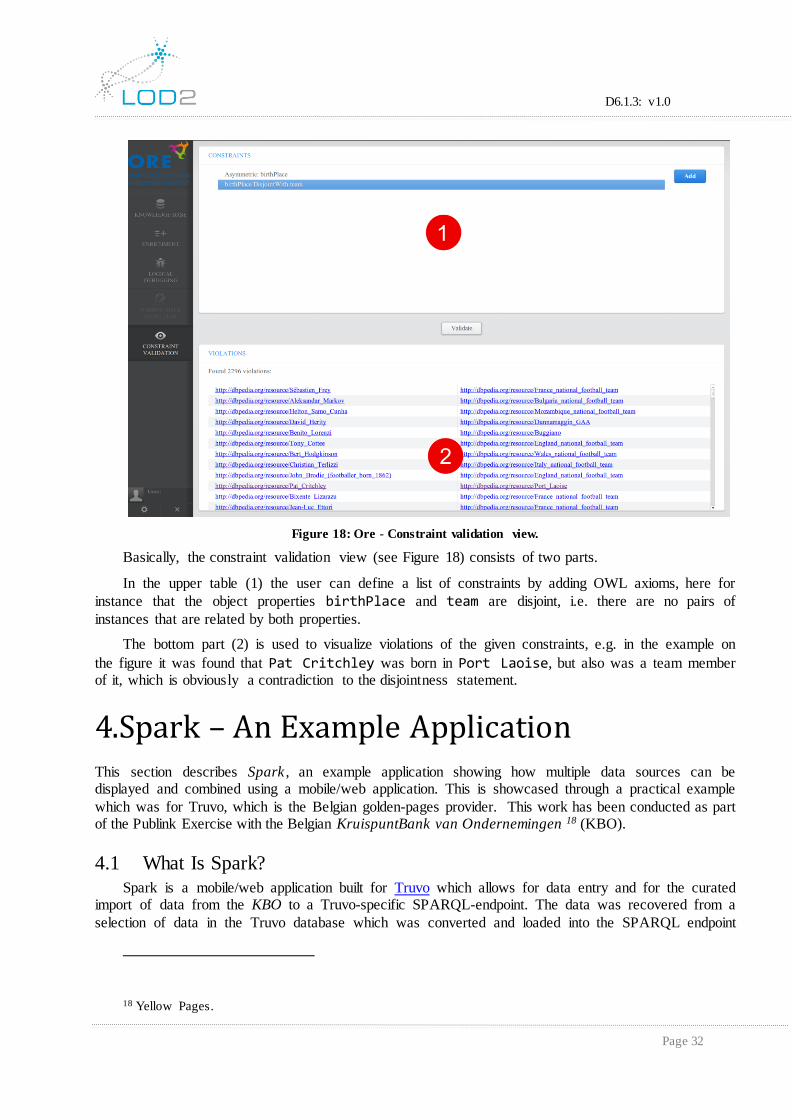
Figure 18: Ore - Constraint validation view.
Basically, the constraint validation view (see Figure 18) consists of two parts.
In the upper table (1) the user can define a list of constraints by adding OWL axioms, here for
instance that the object properties birthPlace and team are disjoint, i.e. there are no pairs of
instances that are related by both properties.
The bottom part (2) is used to visualize violations of the given constraints, e.g. in the example on
the figure it was found that Pat Critchley was born in Port Laoise, but also was a team member of it, which is obviously a contradiction to the disjointness statement.
4. Spark – An Example Application This section describes Spark , an example application showing how multiple data sources can be displayed and combined using a mobile/web application. This is showcased through a practical example
which was for Truvo, which is the Belgian golden-pages provider. This work has been conducted as part of the Publink Exercise with the Belgian KruispuntBank van Ondernemingen 18 (KBO).
4.1 What Is Spark?
Spark is a mobile/web application built for Truvo which allows for data entry and for the curated import of data from the KBO to a Truvo-specific SPARQL-endpoint. The data was recovered from a
selection of data in the Truvo database which was converted and loaded into the SPARQL endpoint
18 Yellow Pages.
D6.1.3: v1.0
Page 33
using the lod-manager19 (the prov, org and vCard vocabularies where used with the initial SPARQL queries developed/defined using the approach described in Section 0). Discovery of entries to import
and validate happens through browsing a location-based mobile or web interface as shown in Figure 20.
Displaying data is shown in Figure 21 and data import is shown in Figure 22: Spark – Importing Data.
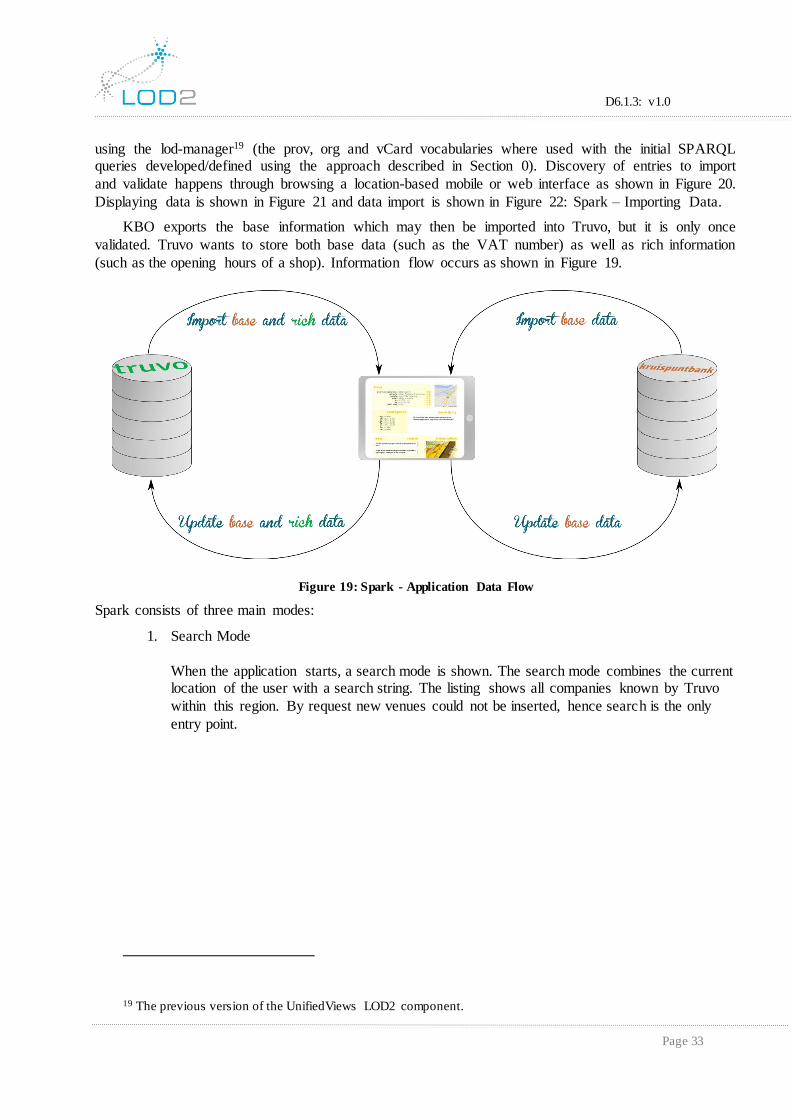
KBO exports the base information which may then be imported into Truvo, but it is only once
validated. Truvo wants to store both base data (such as the VAT number) as well as rich information
(such as the opening hours of a shop). Information flow occurs as shown in Figure 19.
Figure 19: Spark - Application Data Flow
Spark consists of three main modes:
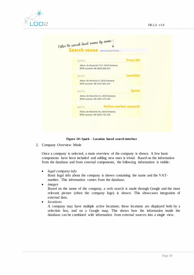
1. Search Mode
When the application starts, a search mode is shown. The search mode combines the current location of the user with a search string. The listing shows all companies known by Truvo
within this region. By request new venues could not be inserted, hence search is the only
entry point.
19 The previous version of the UnifiedViews LOD2 component.
D6.1.3: v1.0
Page 34
Figure 20: Spark – Location based search interface
2. Company Overview Mode
Once a company is selected, a main overview of the company is shown. A few basic
components have been included and adding new ones is trivial. Based on the information from the database and from external components, the following information is visible:
legal company info Basic legal info about the company is shown containing the name and the VAT-
number. This information comes from the database.
images Based on the name of the company, a web search is made through Google and the most
relevant picture (often the company logo) is shown. This showcases integration of
external data.
locations
A company may have multiple active locations; these locations are displayed both by a
selection box, and on a Google map. This shows how the information inside the database can be combined with information from external sources into a single view.

D6.1.3: v1.0
Page 35
Figure 21: Spark – Company Overview
3. Edit Mode multiple levels of editing are possible. In the edit mode, the base KBO information can be
imported, forming the start of the new information. Existing data can also be edited. The interface for this is based on the requested type of entry and on the type of information to
enter (see this topic for more info).

D6.1.3: v1.0
Page 36
Figure 22: Spark – Importing Data
4.2 Spark's High-Level Architecture
From a high-level point of view, Spark consists of a web/mobile html5 application which connects to two (possibly curated) SPARQL endpoints. One of these endpoints must have SPARQL update
semantics enabled and should support Virtuoso 7's geo-support and search functionality.
Figure 23: Spark – High-Level connections
As a base application framework on the frontend, Backbone.js – a simple Web-MVC framework –
is used to drive the application. The location is retrieved through the HTML5 geolocation API. The
implementation of this API is either supplied by the browser (for desktop use) or by Phonegap/Cordova (for mobile web apps). For the general style of the application, Twitter Bootstrap v3 was used with
theming based on Truvo's inhouse Twitter Bootstrap v2 style guide. For brevity and clarity, code was written using coffeescript, a language which compiles back to javascript.

D6.1.3: v1.0
Page 37
Figure 24: Spark – Components and Used Technologies
An overview of the architecture is shown in Figure 19. In order to demonstrate that a semantic data model can be used at all levels of application development, it is necessary to show that it is sufficient for
the most expressive layer, this being the frontend and without unreasonable effort. This means that the
model layer of the javascript application uses SPARQL queries to update the data model on the server side and the model is built on top of that. An interface may be offered at any level for added security,
which means that the necessary SPARQL endpoints would move to that layer. At which place access
security is best enforced is application specific. A Ruby on Rails layer exists through which all SPARQL queries pass and which could be used to enforce constraints on the allowed queries and
updates. Security was not a focus for this project.
4.3 Application Logic with Linked Data
The model layer of modern web applications needs extending in order to interoperate easily with
linked data.
Current best practices for web applications often base themselves on a model-view-controller architecture. The interpretation of this architecture tends to differ between frameworks, but the general
concepts can nearly always be identified. In this architecture, the model layer contains the business
logic, the view layer displays content and accepts user input, and the controller layer connects both of them together by parsing the user requests and altering the model accordingly. The model layer is used
to keep the content in sync with the content of the database. Hence the classes in the model layer need to
map to the content of the database. A synchronization layer to import linked data into the objects of a model layer was not found.
D6.1.3: v1.0
Page 38
Mapping the content of linked data to a traditional model yields a few problems. Assumptions in Backbone.js’s core model layer (similar can be found in nearly all related frameworks) are incompatible with the model of linked data. One of the core assumptions is that a property in the model has a single value; another is that variables have 'simple' names instead of URIs. A last problem is that some values lie close to language primitives, but aren't (e.g: a URI is a lot like a String, but it isn't). This section describes how these problems were tackled for the Truvo application. Although the solutions chosen here are certainly not the only viable options, the patterns which can be derived from this can be ported to other applications, frameworks or even languages.
4.3.1 Making the Model Linked-Data Aware
For the Truvo application, the Backbone.js Model layer has been extended to support multiple values for each property. The extension offers a transitional interface, so layers which aren't aware of
this change still behave as expected.
In linked data the assumption is made that each predicate could –in general– have more than one value for a given subject. Constraints can be placed on the model, but this is not the case by default. In traditional programming, the properties of a model are –in general– assumed to contain only a single value. The assumption that each property in the model has a single value ripples through to the controller and the view layer. Ideally, one would only want to extend the model layer and let previous assumptions hold as a default case in the other layers. Only extending on it where the use of multiple values could have an added benefit. The core backbone model was extended to support this use in the NamespacedObject class. The general construction could be repeated in other frameworks or languages.
Much of the power of linked data arises by attaching new content to known objects. By using URIs as properties it is possible to attach new information to objects without interfering with the already known information. Especially in mobile applications, where data from multiple sources is expected to be shown and imported, support for such features is important. The main downside of this is that URIs tend to be rather long and that languages often don't have support for such strings. A variable name in javascript may not contain a % or colon, to name a few issues. Many modern javascript frameworks use getter and setter functions which use a string as an identifier, hence URIs can be specified. For Truvo, the support for using URIs with prefixes has been extended, as known from SPARQL queries, which makes the usage of this extended model clear and intuitive.
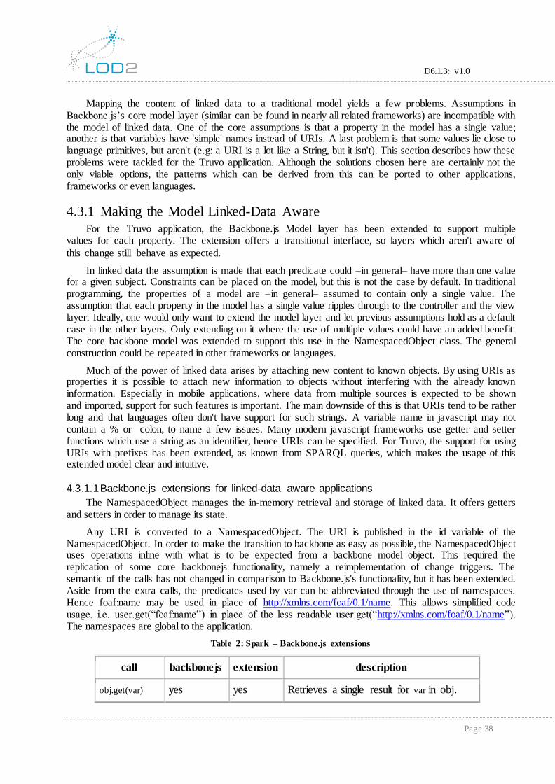
4.3.1.1 Backbone.js extensions for linked-data aware applications
The NamespacedObject manages the in-memory retrieval and storage of linked data. It offers getters and setters in order to manage its state.
Any URI is converted to a NamespacedObject. The URI is published in the id variable of the NamespacedObject. In order to make the transition to backbone as easy as possible, the NamespacedObject uses operations inline with what is to be expected from a backbone model object. This required the replication of some core backbonejs functionality, namely a reimplementation of change triggers. The semantic of the calls has not changed in comparison to Backbone.js's functionality, but it has been extended. Aside from the extra calls, the predicates used by var can be abbreviated through the use of namespaces. Hence foaf:name may be used in place of http://xmlns.com/foaf/0.1/name. This allows simplified code usage, i.e. user.get(“foaf:name”) in place of the less readable user.get(“http://xmlns.com/foaf/0.1/name”). The namespaces are global to the application.
Table 2: Spark – Backbone.js extensions
call backbonejs extension description
obj.get(var) yes yes Retrieves a single result for var in obj.

D6.1.3: v1.0
Page 39
call backbonejs extension description
obj.getAll(var) no yes Retrieves all values var has in obj.
obj.set(var,val) yes yes Stores the value for var in obj, removing all other values.
obj.add(var,val) no yes Adds val to the list of values obj has for
var.
obj.longKeys() no yes Retrieves all variables stored in obj,
expanding all namespaces.
obj.shortKeys() no yes Retrieves all variables stored in obj, compacting all namespaces.
4.3.2 Coping with Language Types
Another issue lies in the creation and display of linked data primitive values. URIs look a lot like strings, and we'd prefer to treat them similarly, but they aren’t the same thing. How this can be tackled is
heavily dependent on the underlying programming language.
Some languages, like Ruby, allow the extension of core classes with new functionality. In these classes the core String class could be extended to represent a URI. Other languages don't allow users to
extend primitive values at all, like Java. In these languages a separate class with necessary String-like
support has to be rebuilt entirely. Javascript lies somewhere between these approaches. Although javascript is a prototype-based language, some objects are considered primitives and cannot be
extended. Strings lie somewhere in between a primitive value and a prototype based object.
For example, it is not possible to extend a string and treat it as a native string. It is, however, trivial
to wrap a string in a prototype object and add properties to that prototype. This is the approach used for
URIs in this implementation. This approach allows additional properties to be added to the string and still have it behave mostly like a string. Some operations aren't clean, namely:
string comparison
As these are new instances, standard string comparison does not work as expected.
printing
When a string is printed in the console, it is printed as an array of characters, rather than as
a nice string.
concatenation
String concatenation does not propagate the custom properties.
Although it is possible to extend strings, and it's not even particularly complex, the syntax towards
the programmer isn't as pretty as could be hoped for. Few issues have been encountered with the current
approach as the differences have been hidden wherever possible, but it does clutter the code in the backend.
4.3.3 Synchronizing the Model State with the Database
Given a model that is linked-data aware, synchronization is to be tackled. The construction for this
application required the information of the model to be retrieved from multiple sources and the model
D6.1.3: v1.0
Page 40
itself to be written to a single source. An implementation was built which, given the URI of an object, reads the triples from the store and builds the model from there on onward. Once a model has been
retrieved, it may be retrieved from another source, which yields a new object with the content of the
other source. Information can easily be copied and saved across applications.
4.3.3.1 Lessons learnt
The Technical realization of consists of the synchronization on one end and coping with multiple
graphs/sources on the other end.
1. Synchronizing the model state with the database
Objects are identified by their URI. All triples accessible through this triple in a forward-referencing manner are maintained by the model object.
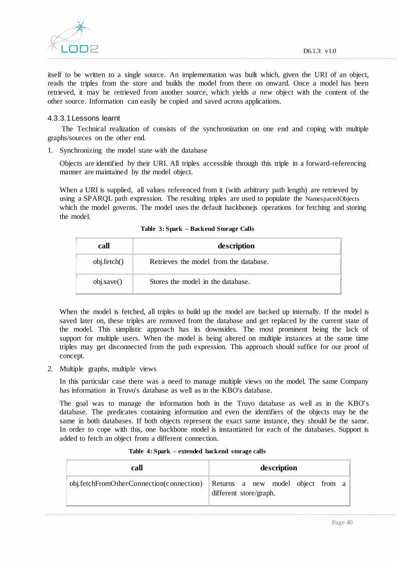
When a URI is supplied, all values referenced from it (with arbitrary path length) are retrieved by using a SPARQL path expression. The resulting triples are used to populate the NamespacedObjects
which the model governs. The model uses the default backbonejs operations for fetching and storing
the model.
Table 3: Spark – Backend Storage Calls
call description
obj.fetch() Retrieves the model from the database.
obj.save() Stores the model in the database.
When the model is fetched, all triples to build up the model are backed up internally. If the model is
saved later on, these triples are removed from the database and get replaced by the current state of the model. This simplistic approach has its downsides. The most prominent being the lack of
support for multiple users. When the model is being altered on multiple instances at the same time triples may get disconnected from the path expression. This approach should suffice for our proof of
concept.
2. Multiple graphs, multiple views
In this particular case there was a need to manage multiple views on the model. The same Company
has information in Truvo's database as well as in the KBO's database.
The goal was to manage the information both in the Truvo database as well as in the KBO's database. The predicates containing information and even the identifiers of the objects may be the
same in both databases. If both objects represent the exact same instance, they should be the same. In order to cope with this, one backbone model is instantiated for each of the databases. Support is
added to fetch an object from a different connection.
Table 4: Spark – extended backend storage calls
call description
obj.fetchFromOtherConnection(connection) Returns a new model object from a
different store/graph.
D6.1.3: v1.0
Page 41
Storing and retrieving works through fetch and save as on any backbone model. Importing
information from one database to another is done by copying the NamespacedObject from one
object to the other.
4.4 Constructing User Interfaces for Linked Data
The technical challenge of constructing linked data information in the model needs to be overcome
in order to build user interfaces with greater expressivity than what's common. Much of the power of linked data lies in treating data as content with a semantic meaning. As the model layer keeps all
semantic content present, the user interface can use the semantic model to generate the required views.
The construction works similarly to context oriented programming, in which both the context as subject decide how a particular operation or view is supposed to behave.
For example: consider the intention to render a lot of objects in a listing. For a person, the full name
of the person is a clean representation in the list. For an address, the street name and number, city and country could be sufficient. If a list should be rendered containing both addresses and names, then this
should be possible as well.
The construction of views becomes a lot more declarative by defining the way an instance should
be rendered based on the type of the object and the form of display. There is no need to consider what
should happen when the two of them collide. Yet knowledge of the domain can still be relied upon when this is necessary.
Consider, for instance, the entry of an address field. Although it is not important that the address is
shown in a list with other objects, there might still be solid knowledge about what should be filled in about the address. It is possible – for instance– to assume that the street name is a string.
4.4.1 Context-Aware Components - Spark
To provide a system which derives the correct views to render based on the information available in the application, SmartView and ActiveEditor definitions where developed (see below). Both generate
the correct view based on both the data in the database, as well as the code which has been specified to
handle them. They are defined in more detail below.
In all occasions, it took a while to wrap around these meta-systems. However, the code is easy to
look at, and the automated part seldomly contains errors. In a proof-of-concept, like Spark, it is hard to
justify an extensive use of meta-programming in terms of development speed. Yet the lessons learned can be ported to other applications. Even in moderately-sized applications, it may pay off in
development time and the resulting code is expected to contain much less errors due to oversights.
1. SmartView
The SmartView renders a set of views based on the triples available in the store. What is available in the detailed view of a Company may depend on what type of company it is and which extra
attributes have been specified on it. A company may have many enabled views, for each of these
views the correct backbone view is instantiated automatically. The main task of the frontend programmer thus becomes the implementation of the right views, they needn't be bothered with
which views will be shown in which situations anymore. Which views are to be rendered has
become a business decision with rules stored in the database and enforced by the SmartView.
2. ActiveEditor
D6.1.3: v1.0
Page 42
The ActiveEditor is shown when editing a company's locations. In this view, a single predicate of a single object is always being edited. However, these predicates may have multiple values, hence
lists need to be shown. Various objects may be stored in these lists, and the tree structure governing
them may be deeply nested. A programmer should not be bothered with the type of instances which may potentially be supplied as the value for an attribute, it would quickly become too complex and
would be error-prone. What may be specified in the database should be enforced in the model layer,
it should not be relied on by the frontend if it is not necessary.
The ActiveEditor allows the user to specify renderers for objects based on their type and a facet. The
facet indicates the type of rendering for the object. The "list"-facet, for instance, indicates that the object will be shown in a list of similar objects. The specification of a renderer is done through a
factory method which limits the code the programmer needs to write, but still allows the
programmer to override any automatically-generated functionality. The view is still a fully functional backbone view and thus has all the freedom to render and update the model as it would be
with a full manual specification. However, now it may use the rendering system to discover and
display the views of its children. In some occasions the definition of a renderer is little more than specifying the template which should be rendered.
4.5 Final Comments
This proof of concept has showcased two major features:
1. By using well-defined models, data from multiple sources can easily be integrated with one another.
2. With the right base construction, flexible and expressive applications can be built on top of linked data.
It has also been shown that this can be accomplished using mostly traditional frameworks, although
some extensions were required. There were some issues with backbone.js as a base framework and would use a more modern framework if this exercise were to be repeated. This approach shows great
promise for mobile web applications based on linked data.
5. Repeatable Reporting Using SPARQL 5.1 Introduction
Org-Mode is a very well-known major mode for GNU/Emacs, providing personal organisational facilities for developers and power-editor users20. It has a large number of configuration possibilities,
but the only ones described here, will be those related to the two simple use-cases outlined below21.
These were selected to show the potential of lower-level possibilities for UI integration which can still be practically interesting.
Integrating data from different sources, discussing transformations, mappings and ontologies often requires a document trace of the decisions and status of the work. One problem is that typically, the
SPARQL queries are not always documented in a visible fashion and in a way where changes in the
20 Power-users in the sense that they are comfortable using keyboard control sequences, rather than menu selections (as in word or
open-office).
21 These examples are summaries of real usages, but which came about because of the need to document not just the SPARQL
queries, but how it was arrived at.

D6.1.3: v1.0
Page 43
models can be described. The main requirements for the LOD2 stack components (D6.2.3) are that the data is in RDF and that it should be accessible via a SPARQL end-point(s). These requirements opened
up the possibility to use org-mode to document such mappings because of its “literate programming” 22support (which was investigated and described very briefly here).
In the following it is shown how org-mode supports these users, via its “literate programming”
facilities to improve the specification, development, refinement and testing of the SPARQL queries and
transformations. To illustrate the usage of org-mode two use-cases which are described which come from existing usages23:
1. The first is that of a Linked Data producer who wishes to define a QA report for the RDF data
available. 2. The second is that of a user designing the mapping rules to be used by a tool such as the lod-
manager (previous version of UnifiedViews).
The examples are taken from the Open Data Support (ODS) project24 in which all the meta data of the available national open data portal is aggregated into a harmonized view.
5.2 What Is Required to Start
The minimal requirements for setting up to use this are to install the following (all of which are
open-source components):
GNU/Emacs (23.3.5 or later),
Org-Mode (latest version from 25),
Roqet (rasqal package) to be installed,
load-library the “ob-roqet.el”(which is a trivially modified variant of the awk script
5.3 Using Org-Mode
The following is not an introduction to org-mode, but just a summary intended to show the
potential which is present because of the use of SPARQL and the common vocabularies (for more information there are many good org-mode tutorials available). Org-mode is purely text-based with
GNU/Emacs functions operating on the text when requested by the document editor (e.g. refresh results,
or export the file in a requested format).
The main integration (or configuration) point is a modification which simply calls the command
line tool ‘roqet’ on the provided SPARQL end-point (and puts the results in the document being edited and if needed in the document to eventually be exported). The textual form of this in the file has the
form below where the SPARQL commands are surrounded by #+BEGIN_SRC:.. #+END_SRC.26
22 Literate programming is a way of developing/document code which focusses a great deal on the documentation of the source code (both the source code and the documentation being maintained in the same text file). The weaving of the text files then extracts the
source code files and the readable forms of the documents.
23 KBO data migration and the dataset recovery for the ODS project.
24 See http://data.opendatasupport.eu
25 http://orgmode.org/
26 :endpoint <sparql-endpoint> is the sparql end point to access to execute the query (here a local URI was used for
a local endpoint, but any accessible end point can be used).

D6.1.3: v1.0
Page 44
Listing 2.2.1:
#+NAME: results1
#+BEGIN_SRC roqet :endpoint http://192.168.33.33/sparql
SELECT
COUNT(DISTINCT ?g) AS ?graphs
COUNT(DISTINCT ?s) AS ?subjects
COUNT(DISTINCT ?p) AS ?predicates
WHERE {
graph ?g {
?s ?p ?o .
} } #+END_SRC
When evaluation of this SRC block is requested, this calls the ‘roqet’ command line tool which,
using the SPARQL end-point, evaluates the query. The results are returned CSV line and represented in the document as a table (As can be seen in Figure 28: Org-Mode - Example Results/Graph). These
results can in turn be fed into other command line tools (as they can in UNIX/linux) or snippets of code
for summarising further the results or for plotting graphs (e.g. gnuplot).
5.4 Use Cases
5.4.1 UC1: Data QA Report Creation
Here the requirement is often, to access the 'data', execute queries and then report on the 'state' of
the data, which could include such things as:
the number of concepts,
the number of properties which not used,
changes in the data volumes27,
the validation of the data and potentially the identification of transformation problems:
o which might well mean recording the query and results which caused the problem.
o rerunning the same query later when the problem has been 'fixed'.
With all of these, the problem is that once the SPARQL query is posted in a bug-reporting system it
becomes 'inactive' to a certain extent or the discussion moves away and gets summarised elsewhere.
The purpose of this sort of QA usage can equally well be to investigate or to understand the data.
From this understanding changes can be recommended, bug reports can be made, etc.
The following is a simple example of a query made on the RDF data which can be found at
htpp://opendatsupport.eu/sparql28. This initial RDF data is produce via the use of the lod-manager (i.e.
previous version of UnifiedViews). This is then mapped to a new form via a sequence of plugins, resulting RDF triples using DCAT and other vocabularies:
27 This would require time stamping the data recovered and storing the recovered instances across calls so that they
can be compared.
28 Internal copy of it.
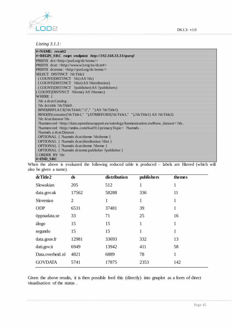
D6.1.3: v1.0
Page 45
Listing 3.1.1:
#+NAME: result2
#+BEGIN_SRC roqet :endpoint http://192.168.33.33/sparql
PREFIX dct:<http://purl.org/dc/terms/>
PREFIX dcat: <http://www.w3.org/ns/dcat#>
PREFIX dcterms: <http://purl.org/dc/terms/>
SELECT DISTINCT ?dcTitle2
( COUNT(DISTINCT ?ds) AS ?ds)
( COUNT(DISTINCT ?dist) AS ?distribution)
( COUNT(DISTINCT ?publisher) AS ?publishers)
( COUNT(DISTINCT ?theme) AS ?themes)
WHERE {
?dc a dcat:Catalog .
?dc dct:title ?dcTitle0 .
BIND(REPLACE(?dcTit le0,"\\|"," ") AS ?dcTitle1)
BIND(IF(contains(?dcTitle1," "),STRBEFORE(?dcTit le1," "),?dcTitle1) AS ?dcTitle2)
?dc dcat:dataset ?ds .
?harmrecord <http://data.opendatasupport.eu/ontology/harmonisation.owl#raw_dataset> ?ds .
?harmrecord <http://xmlns.com/foaf/0.1/primaryTopic> ?harmds .
?harmds a dcat:Dataset .
OPTIONAL { ?harmds dcat:theme ?dstheme }
OPTIONAL { ?harmds dcat:distribution ?dist }
OPTIONAL { ?harmds dcat:theme ?theme }
OPTIONAL { ?harmds dcterms:publisher ?publisher }
} ORDER BY ?dc #+END_SRC
When the above is evaluated the following reduced table is produced – labels are filtered (which will also be given a name).
dcTitle2 ds distribution publishers themes
Slowakian 205 512 1 1
data.gov.uk 17562 58288 336 11
Slovenian 2 1 1 1
ODP 6531 37481 39 1
öppnadata.se 33 71 25 16
álogo 15 15 1 1
segundo 15 15 1 1
data.gouv.fr 12981 33693 332 13
dati.gov.it 6949 13942 411 58
Data.overheid.nl 4821 6889 78 1
GOVDATA 5741 17875 2353 142
Given the above results, it is then possible feed this (directly) into gnuplot as a form of direct visualisation of the status .
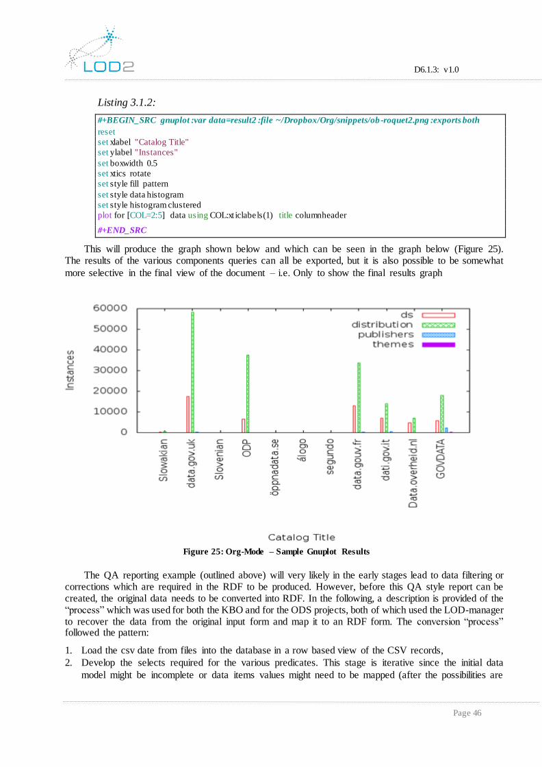
D6.1.3: v1.0
Page 46
Listing 3.1.2:
#+BEGIN_SRC gnuplot :var data=result2 :file ~/Dropbox/Org/snippets/ob -roquet2.png :exports both
reset
set xlabel "Catalog Title"
set ylabel "Instances"
set boxwidth 0.5
set xtics rotate
set style fill pattern
set style data histogram
set style histogram clustered
plot for [COL=2:5] data using COL:xt iclabels(1) title columnheader
#+END_SRC
This will produce the graph shown below and which can be seen in the graph below (Figure 25). The results of the various components queries can all be exported, but it is also possible to be somewhat
more selective in the final view of the document – i.e. Only to show the final results graph
5.4.2 UC2: Documenting the Mapping Discovery The QA reporting example (outlined above) will very likely in the early stages lead to data filtering or
corrections which are required in the RDF to be produced. However, before this QA style report can be created, the original data needs to be converted into RDF. In the following, a description is provided of the “process” which was used for both the KBO and for the ODS projects, both of which used the LOD-manager to recover the data from the original input form and map it to an RDF form. The conversion “process” followed the pattern:
1. Load the csv date from files into the database in a row based view of the CSV records,
2. Develop the selects required for the various predicates. This stage is iterative since the initial data
model might be incomplete or data items values might need to be mapped (after the possibilities are
Figure 25: Org-Mode – Sample Gnuplot Results

D6.1.3: v1.0
Page 47
identified). Example queries could then be (note: orig in the sample query below refers to the original data namespace):
Listing 3.2.1:
#+BEGIN_SRC roqet :endpoint http://192.168.33.33/sparql
PREFIX dcat: <http://www.w3.org/ns/dcat#>
PREFIX dct: <http://purl.org/dc/terms/>
PREFIX orig: <http://www.data.gouv.fr/predicate/>
SELECT DISTINCT ?ds ?o
WHERE {
?ds a dcat:Dataset .
?ds orig:title ?o . } LIMIT 10 #+END_SRC
Which will when evaluated, result in the following:
ds o
http://www.data.gouv.fr/dataset/communication-dp Communication
http://www.data.gouv.fr/dataset/cadastre-mtn Cadastre
http://www.data.gouv.fr/dataset/monuments-mtn Monuments
http://www.data.gouv.fr/dataset/monuments Monuments
http://www.data.gouv.fr/dataset/te-1 Test
http://www.data.gouv.fr/dataset/te-2 Test
http://www.data.gouv.fr/dataset/population Population
http://www.data.gouv.fr/dataset/populati-1 Population
http://www.data.gouv.fr/dataset/populati-0 Population
http://www.data.gouv.fr/dataset/pensions-dp Pensions
3. Test and check that the results are as clean as possible, very likely recording any results which are not clear or where the results are ambiguous,
4. Finally, develop the necessary INSERT statement required for inclusion in the LOD-manager (which
should be the same as the select statement, but with additional management mappings). For example:
Listing 3.2.2:
#+BEGIN_SRC roqet :endpoint http:// http://192.168.33.33/sparql
PREFIX orig: <http://www.data.gouv.fr/predicate/>
PREFIX dcat: <http://www.w3.org/ns/dcat#>
PREFIX dct: <http://purl.org/dc/terms/>
INSERT {
?harmds dct:title ?title
} WHERE {
?harmrecord <http://data.opendatasupport.eu/ontology/harmonisation.owl#raw_dataset> ?ds .
?harmrecord <http://xmlns.com/foaf/0.1/primaryTopic> ?harmds .
?ds a dcat:Dataset .
?ds orig:title ?title .
}
#+END_SRC
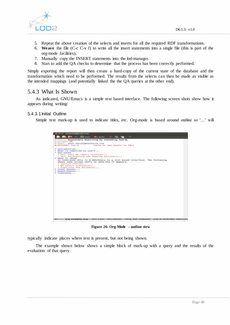
D6.1.3: v1.0
Page 48
5. Repeat the above creation of the selects and inserts for all the required RDF transformations. 6. Weave the file (C-c C-v f) to write all the insert statements into a single file (this is part of the
org-mode facilities),
7. Manually copy the INSERT statements into the lod-manager. 8. Start to add the QA checks to determine that the process has been correctly performed.
Simply exporting the report will then create a hard-copy of the current state of the database and the
transformation which need to be performed. The results from the selects can then be made as visible as the intended mappings (and potentially linked the the QA queries at the other end).
5.4.3 What Is Shown
As indicated, GNU/Emacs is a simple text based interface. The following screen shots show how it appears during writing/
5.4.3.1 Initial Outline
Simple text mark-up is used to indicate titles, etc. Org-mode is based around outline so '…' will
typically indicate places where text is present, but not being shown.
The example shown below shows a simple block of mark-up with a query and the results of the evaluation of that query.
Figure 26: Org-Mode – outline view

D6.1.3: v1.0
Page 49
Figure 27: Org-Mode - Simple example
5.4.3.2 Simple graph
The screenshot below shows the sample file.
Figure 28: Org-Mode - Example Results/Graph

D6.1.3: v1.0
Page 50
5.4.3.3 Exporting the documents
Exporting the documents is one of the basic functions of org-mode, and there are several format
available (e.g. ODT, markdown or PDF), but the screenshot below is for Libre-Office (ODT).
One thing of interest, is that when the document is exported or a gnuplot picture refreshed then any
results on which that block is dependent are recomputed (so all SPARQL queries which are required to
compute the graphs, tables, etc. would be (re)evaluated to produce their results). The document would then be completely up-to-date.
5.5 Some Final Points
This development process has been used in the KBO and ODS29 projects to document the translation and to define the SPARQL queries required in the data migration. The GNU/Emacs org-
mode has very impressive support for making the documents more ‘active’, with relatively easy updates
to one of the open-source modules for configuring it for interacting with SPARQL.
The same approach could be used with a RDBMS, but it is not typical for a RDBMS to be made
available over the internet (security, etc.). SPARQL read-only end-points are intended to be made
available on the web and start from that point of view. Even if an RDBMS based database is made available, the database schema would still have to be published and that is often not available. In this
area the use of standard linked data vocabularies means that the queries can be written which use
multiple SPARQL end-points.
29 Both projects at Tenforce.
Figure 29: Org-Mode - Exported to Open-Office

D6.1.3: v1.0
Page 51
However, the main point is that making the data available via a SPARQL end-point and with clearly defined and shared vocabularies allows this sort of use/process, without the need to create a new
GUI for each required function. Sometimes, simple configuration and tools, can lead to improved
results. This was a practical usage which was not anticipated, which simply started from the requirement to document the SPARQL queries, and for which almost everything was already available (just finding
the configuration possibilities was required).
D6.1.3: v1.0
Page 52
6. Lessons Learnt and Conclusions In this section, the lessons learnt from D6.1.1, D6.1.2 and the final year are summarised, with a
view to indicating a route which should be taken for simplifying the development of future systems. The main points being:
UI Integration is a multi-facetted operation which takes a great deal of time and effort and it is
important to not be too restrictive in the definition of what is a user interface:
Web UI components are just one form of interface and component description, which needs to
be abstracted,
Command-line interfaces are also user interfaces and it’s just the user type that is different,
Simpler forms of integration can sometime lead to improved processes for certain use-cases
(Page 44).
Opening up access to lower levels can often reduce the need for changes at the UI level.
Using common vocabularies and SPARQL improves greatly the integration possibilities since it:
can open up the data to unintended and more traditional toolsets (Page 42),
facilitates the potential to glue together multiple data sources (Page 42) without having to resort
to migrating/mapping the data (there will always be differences in data quality, etc.)
The use of a global packaging system (described D6.2.3) improves greatly the accessibility of the
various components and the potential for integration, but
Does not guarantee that a package component will be reused (as was the case with the web API facilities),
Component reuse follows the normal reuse patterns, local reuse first and remote reuse later
Packages can change frequently, become orphaned or obsoleted.
The Deliverable has focussed on the User Interfaces, from the GUI to the purely text-based
integrations. Three additional web-based UI interfaces have been described along with an example
application which was built to demonstrate the possibilities on a Mobile platform. All these have some aspect which will be usable in the future, but that will be dictated by the application user requirements.

D6.1.3: v1.0
Page 53
7. References [D6.1.1] Deliverable 6.1.1 - Initial Release of Integrated LOD2 Stack UI Components
[D6.1.2] Deliverable 6.1.2 – Intermediate Release of Integrated LOD2 Stack UI Components
[D6.2.2] Deliverable 6.2.2 – Intermediate Release of the LOD2 Stack
[AppInt1] Application Integration on the User Interface Level: an Ontology-Based Approach, http://www.heikopaulheim.com/docs/dke_2010.pdf, Heiko Paulheim and Fabian Probst,
SAP Research Centere Darmstadt.
[AppInt2] Understanding UI Integration: A survey of problems, technologies and opportunities, Florian Daniel et al.
[Reuse1] http://www.cse.wustl.edu/~schmidt/reuse-lessons.html
[GPLT] Gnuplot, http://www.gnuplot.info/
[GORG] Org-Mode, http://orgmode.org/