Embed Size (px)
Citation preview
FP7-Security EULER
Deliverable 3.5 – Waveform and Spectrum management specification Public report 1/91
EULER
Deliverable 3.5
High-data-rate spectrum aware radio access technique definition
Version 1.0
Deliverable manager Contributors Checked by
Mr Delmas Serge (EADS DS)
Ms Helias-Foret Christine (EADS DS)
Mr Gyozo Godor (University of Budapest) Ms Lehtomäki Janne (Center of
wireless communication) Ms Vartiainen Johanna (Center of wireless communication)
Mr Braysy Timo (Center of
wireless communication) Mr Schmidt Sami (Elektrobit)

FP7-Security EULER
Deliverable 3.5 – Waveform and Spectrum management specification Public report 2/91
Document lifecycle
Revision number
Date Contributor Evolution
1.0 November, 2010 see front page Document creation

FP7-Security EULER
Deliverable 3.5 – Waveform and Spectrum management specification Public report 3/91
Table of contents
1 ACRONYMS.................................................................................................................... 5
2 DEFINITIONS................................................................................................................ 5
3 EXECUTIVE SUMMARY .................................................................................................. 6
4 INTRODUCTION............................................................................................................ 7
4.1 PROJECT SCOPE ............................................................................................................7 4.2 PURPOSE OF THE DOCUMENT.............................................................................................7
5 SPECTRUM ACCESS IN CURRENT MOBILE WIRELESS NETWORKS .............................. 7
5.1 LICENSE-EXEMPT WIMAX SYSTEM RESUME ...........................................................................7 5.2 WIFI SYSTEM ...............................................................................................................9 5.3 IDEAS INTERESTING FOR EULER......................................................................................10
6 EULER PMR MOBILE BROADBAND NETWORK DESCRIPTION .................................... 10
6.1 EULER NETWORK DESCRIPTION ......................................................................................11 6.2 RELAY STATIONS IN AN EULER PMR MOBILE BROADBAND NETWORK .........................................12
6.2.1 Entry of a Relay Station in an EULER PMR Mobile Broadband network : Dynamic Frequency Selection (DFS)................................................................................................13 6.2.2 Mobile station services..........................................................................................13
6.3 MOBILE STATIONS IN AN EULER PMR MOBILE BROADBAND NETWORK .......................................14 6.3.1 Mobile Stations declaration....................................................................................14 6.3.2 Mobile Stations entry in an EULER PMR Mobile Broadband network............................15 6.3.3 User services .......................................................................................................15 6.3.4 Relay station services ...........................................................................................16
6.4 EULER PMR MOBILE BROADBAND SYSTEMS INTERCONNECTION ...............................................16 6.4.1 Use of specific terminals : the Relay Station interconnection terminals .......................16 6.4.2 Information exchanged between EULER PMR Mobile Broadband systems ...................17
6.5 EULER SPECTRUM DESCRIPTION......................................................................................18 6.5.1 EULER radio element definition..............................................................................18 6.5.2 EULER radio block definition..................................................................................18 6.5.3 EULER radio frame definition.................................................................................19
6.6 DYNAMIC SPECTRUM MANAGEMENT ...................................................................................19 6.6.1 Radio block sensing..............................................................................................19 6.6.2 Radio resource mapping .......................................................................................20 6.6.3 Radio resource allocation ......................................................................................20 6.6.4 Radio block allocation...........................................................................................22 6.6.5 Flow-chart of a dynamic spectrum management algorithm........................................24
7 SPECIFICATION OF CORRESPONDING APPLICATION PROGRAMMING INTERFACES (API) ................................................................................................................................... 24
7.1 EULER RADIO BLOCKS OCCUPANCY MAP FACTORY .................................................................25 7.2 EULER RADIO BLOCK MEASUREMENT SCHEDULER ..................................................................26 7.3 EULER RADIO BLOCK ALLOCATION SCHEDULER.....................................................................28 7.4 DATA DESCRIPTION OF THE RADIO BLOCKS OCCUPANCY MAPPING................................................30
8 APPLICATION OF THE EULER NETWORK TO EXISTING BROADBAND NETWORKS.... 30
8.1 APPLICABILITY OF THE EULER NETWORK TO IEEE 802.16M NETWORK.......................................30 8.1.1 IEEE 802.16m frame structure...............................................................................31 8.1.2 IEEE 802.16m synchronization and system information broadcast..............................32 8.1.3 Mobile station initialization and registration .............................................................33 8.1.4 Radio resources management in IEEE 802.16m.......................................................34

FP7-Security EULER
Deliverable 3.5 – Waveform and Spectrum management specification Public report 4/91
8.1.5 Reference Signals.................................................................................................36 8.1.6 Conclusion ..........................................................................................................37
8.2 APPLICABILITY OF THE EULER NETWORK TO LTE NETWORK ....................................................37 8.2.1 LTE frame structure .............................................................................................37 8.2.2 LTE synchronization and system information broadcast ............................................39 8.2.3 Mobile station registration.....................................................................................46 8.2.4 Radio resources management in LTE......................................................................49 8.2.5 Reference Signals.................................................................................................52 8.2.6 Conclusion ..........................................................................................................54
9 SIMULATION OF THE SPECTRUM SHARING IN AN EULER NETWORK........................ 54
9.1 SIMULATION HYPOTHESES ..............................................................................................54 9.1.1 LTE frame configuration........................................................................................54 9.1.2 Link budget simulation..........................................................................................55 9.1.3 Transmit Power Control configuration.....................................................................57 9.1.4 Power measurements ...........................................................................................58 9.1.5 Radio Block allocation...........................................................................................58 9.1.6 Collisions and interferences ...................................................................................58 9.1.7 Radio Block change function..................................................................................59 9.1.8 Simulated normalized traffic unit............................................................................59 9.1.9 Geographical repartition of the Stations ..................................................................60 9.1.10 Simulation scenario ..........................................................................................61
9.2 SIMULATION RESULTS ...................................................................................................62 9.2.1 The 4 Relay Stations activated...............................................................................62 9.2.2 Comparison with a network with only one active Relay Station ..................................76 9.2.3 Comparison of the results : 4 Relay Stations active / 1 Relay Station active ................79
10 SECURITY ANALYSIS .............................................................................................. 80
10.1 SECURITY ISSUES OF THE DYNAMIC SPECTRUM MANAGEMENT ....................................................80 10.1.1 Security considerations .....................................................................................82 10.1.2 Requirements ..................................................................................................83 10.1.3 Security threats in a Cognitive Radio Network......................................................83
11 CONLUSION............................................................................................................. 90
12 REFERENCES ........................................................................................................... 90

FP7-Security EULER
Deliverable 3.5 – Waveform and Spectrum management specification Public report 5/91
1 Acronyms
ABS BCH Broadcast Channel
AMC Adaptative Modulation and Coding AMS Advanced Mobile Station API Application Programming Interface
BS Base Station DFS Dynamic Frequency Selection DL DownLink FDD Frequency Division Duplex
GPS Global Positioning System HARQ Hybrid Automatic Repeat reQuest LTE Long Term Evolution
MISO Multiple Intputs, Single Output MS Mobile Station OFDM Orthogonal Frequency Division Multiplexing OFDMA Orthogonal Frequency-Division Multiple Access
PMR Private Mobile Radiocommunications QoS Quality of Service RS Relay Station
SDR Software Defined Radio SIMO Single Intput, Multiple Outputs SISO Single Intput, Single Output TDD Time Division Duplex
TDMA Time Division Multiple Access TETRA TErrestrial Trunked RAdio TPC Transmit Power Control
UL UpLink WiMAX Worldwide Interoperability for Microwave Access
2 Definitions
Coexistence Effective common use of a spectrum at the same time and location without harmful interference
Network Set of systems.
System A Base Station or Relay Station and its Mobile Stations.

FP7-Security EULER
Deliverable 3.5 – Waveform and Spectrum management specification Public report 6/91
3 Executive summary
EULER aims is to define and demonstrate how the benefits of SDR can be leveraged in order to drastically enhance interoperability and fast deployment in case of crisis needed to be jointly resolved.
The Task 3.5 (T3.5) proposes a rapidly deployable emergency telecommunication system for public safety responders to increase rapidity and effectiveness interventions of security forces in a crisis. The proposed system must be secured and permit, on a crisis field, on field rescues teams end devices to
share in a cooperative way a common broadband spectrum and to communicate together thanks to standard broadband standardized technologies.
Section 5, a theorical study presents briefly the License-Exempt WiMAX or 802.16h standard and the WiFi standard. The interesting ideas of those two standards, we want to apply to the EULER project are then exposed.
The principes and the topology of an EULER PMR Mobile broadband network are described in section 6. The EULER PMR Mobile broadband network is a wireless on-field communication backbone, made up of nodes which are either intermediate nodes (Relay Stations) or ending nodes (Mobile Stations),
allowing full end-to-end voice and data communications. Thanks to their capability to sense and understand their radio environment, Relay Stations cooperatively maintain network connectivity and share the available spectrum according to the Mobile Stations needs. All the participants of an EULER
PMR Mobile Broadband network will coexist and share a common spectrum band, without interworking nor interfering. An EULER PMR Mobile Broadband network will rely on the following basics :
• a known radio frame structure (section 6.5) and the Relay Stations synchronization and • the sensing of shared radio media (or radio resources) and a common spectrum management
policy (section 6.6). Section 7 presents the Application Programming Interfaces (API) applicable to the spectrum
management. An EULER PMR Mobile Broadband network may be built from existing broadband networks, as IEEE 802.16m or LTE network. The scope of the section 8 is to assess the system aspects the both
broadband standards and to validate their applicabilities to an EULER PMR Mobile Broadband network. The spectrum sharing of an EULER PMR Mobile broadband network has been simulated in LTE thanks
to MATLAB. The simulation scenarii and the associated simulation results are presented section 9. Finally, section 10 presents the conclusion.

FP7-Security EULER
Deliverable 3.5 – Waveform and Spectrum management specification Public report 7/91
4 Introduction
4.1 Project scope
The EULER project will propose solutions to increase rapidity and effectiveness interventions of mixed security forces in a major civil international crisis.
One topic of the project is the study of a new waveform and spectrum management specification.
4.2 Purpose of the document
The EULER SP3 Mobile system is a rapidly deployable wireless mobile communication network, based
on broadband technology as WiMAX or LTE. Because, in some crisis situations, an existing fixed public safety land mobile radio network
infrastructure may not be available, the EULER PMR Mobile Broadband network shall work as a standalone network within emergency response hot spots. Moreover, to efficiently share the available broadband spectrum, dynamic spectrum access shall be
used.
5 Spectrum access in current mobile wireless networks
In the traditional mobile wireless cellular networks as LTE or WiMAX in broadband or as PMR networks, i.e. TETRA or TETRAPOL, in narrow band, are made of Base Stations to which Mobile Stations register. A specific frequency band is allocated to the mobile wireless cellular network
operator. The operator shares by configuration the allocated frequency band between the Base Stations of the wireless network according to the frequency reuse factor which guarantees that a predefined number of interferences between cells in the same geographical area will not be exceeded.
In these kinds of network, the size of the spectrum band allocated by cell is fixed; at the Base Station initialization, the operator sets its allocated spectrum band. In a geographical area, the Base Stations will have an exclusive access to its specific frequency band, Base Stations cannot exchange radio
resources. In 2002, the FCC’s Spectrum Policy Task Force Report [1] identified that public safety community have
significant variability in their spectrum use. Much of the public safety allocated spectrum lies fallow during non-peak periods, but while the peak usage, the entire spectrum band is required.
Our aim is to build a wireless cellular network composed of cells or systems, based on broadband standardized technologies, which will share a common spectrum in a same geographical area. Some standards provide this kind of network. Here are succinctly described :
• in broadband, the License-Exempt WiMAX or 802.16h standard and
• the WiFi standard.
5.1 License-Exempt WiMAX system resume
The License-Exempt WiMAX or 802.16h standard, [6], consists of a 802.16e system to which a form of
spectrum management features have been included. It allows up to three License-Exempt WiMAX Base Stations, in the same geographical area, to share a common frequency band without interfere. This sharing is reliant upon a known frame allocation and network synchronization.

FP7-Security EULER
Deliverable 3.5 – Waveform and Spectrum management specification Public report 8/91
The License-Exempt WiMAX or 802.16h standard is composed of uncoordinated coexistence mechanisms and coordinated coexistence mechanisms :
1. The uncoordinated coexistence mechanisms enable License-Exempt WiMAX systems to coexist. No inter-system communication is needed.
2. The coordinated coexistence mechanisms enable exchange of parameters between License-
Exempt WiMAX system to improve the radio resource allocation while reducing interference. • Information between all the systems of the License-Exempt WiMAX network are
exchanged thanks to a common coexistence control channel, with no need of direct inter-
system communication. • Nevertheless, an inter-system protocol enables License-Exempt WiMAX Base Stations to
dialog via a Mobile Station located under the both coverage. In particular, the inter-
system protocol enables one Base Station to borrow radio resource from another Base Station.
All the License-Exempt WiMAX Base Stations shall be synchronized for example, thanks to a GPS clock.
The License-Exempt WiMAX or 802.16h standard is based on the TDD WiMAX frame structure. A basic License-Exempt WiMAX frame also called CX-frame (coexistence frame) is composed of four WiMAX frames.
The CX-Frame (see Figure 1) is composed of Master, Slave and Shared sub-frames, which can be used for DL or for UL and the optional Common sub-frame which may be used in DL only.
1. During the Common and the Shared sub-frames, communications not affected by interference
may be scheduled. All the systems may operate in parallel. The operation during this sub-frame may require limitations on the transmit power.
2. During the Master sub-frames, a specific system, the Master system, operates. Systems equally share the role of Master system on a rotating basis. No system is allowed to claim
more than one Master sub-frame1. The maximum number of Master systems allowed in a License-Exempt WiMAX network is equal to three.
3. During the Slave sub-frames, the systems, other than the Master system, may operate in the
License-Exempt WiMAX network on condition that they will not interfere the Master system. The Slave sub-frames are only allowed in a License-Exempt WiMAX network when the systems can exchange information thanks to the coordinated coexistence mechanisms. So,
the Master system may, at any time, allow, limit or forbid transmission on Slave sub-frame.
1 Not yet occupied Master sub-frames are considered as shared sub-frames.

FP7-Security EULER
Deliverable 3.5 – Waveform and Spectrum management specification Public report 9/91
Figure 1 shows one CX-frame of a License-Exempt WiMAX filled with three systems. Each system shall be the Master system every four sub-frames.
Master Master Com. Shared Shared Slave Slave Com. Slave Slave Com. CX-frame seen from System 1
Slave Slave Com. Shared Shared Master Master Com. Slave Slave Com.
Slave Slave Com. Shared Shared Slave Slave Com. Master Master Com.
DL DL DL DL UL UL UL UL
Sub-frame 4N - 1 Sub-frame 4N Sub-frame 4N + 1 Sub-frame 4N + 2
CX-frame
Preample, FCH, MAP Time
• System 1 claimed sub_frame 4N, as Master sub_frame of the System 1, • System 2 claimed sub_frame 4N + 1, as Master sub_frame of the System 2, • System 3 claimed sub_frame 4N + 2, as Master sub_frame of the System 3,
CX-frame seen from System 2
CX-frame seen from System 3
Figure 1: License-Exempt WiMAX frame structure
So, thanks to distributed mechanisms, a License-Exempt WiMAX Base Station may set up in a License-Exempt WiMAX network and shall, in a common frequency band, coexist with the other License-Exempt WiMAX Base Stations located on the same geographical area.
But, despite of these qualities, License-Exempt WiMAX standard shows some drawbacks :
1. The number of Base Stations is limited to three per License-Exempt WiMAX frequency band in an area. When the number of Base Stations is superior, another License-Exempt WiMAX
frequency band is needed. 2. The same fixed amount of spectrum is allocated to each Base Station whatever the number of
Base Stations sharing the spectrum band. A Base Station may borrow radio resources from
another Base Station but the negotiations, via a Mobile Station, may last a quite long time, compared to the radio resources allocation in its own channel.
Moreover, a License-Exempt WiMAX network ensures base stations, belonging to different and rival
telecommunication companies, located on the same geographical area, to share a common broadband spectrum without interfering. The access of the radio resources between the base stations is fixed by the License-Exempt WiMAX standard; each base station accesses in an exclusive way to some radio
resources, which does not depend on its real-time needs. So, the base stations, sharing a common license-Exempt WiMAX network, are competing, not cooperating.
Furthermore, even if the entry of a system in a License-Exempt WiMAX network is automatic, the standard has been designed for fixed base stations; base stations in a License-Exempt WiMAX network are not supposed to move in the geographical area.
5.2 WiFi system
A WiFi system is made of stations able to transmit data on the same wireless medium without
interfering nor dialoguing about the medium occupancy.

FP7-Security EULER
Deliverable 3.5 – Waveform and Spectrum management specification Public report 10/91
A WiFi system relies on the Carrier Sense Multiple Access With Collision Avoidance (CSMA/CA) mechanism. When a station wants to transmit information on the medium, it first listens to the
medium for a fixed amount of time. It checks the activity on it. • If the station detects no activities on the medium then it starts its transmission on the
medium. • If the station detects activity on the medium then it waits until medium becomes free.
5.3 Ideas interesting for EULER
The License-Exempt WiMAX and the WiFi standards implement interesting ideas, which could be applied for EULER.
The uncoordinated License-Exempt WiMAX standard relies on a known frame allocation and on system synchronization, but unfortunately the number of License-Exempt WiMAX systems in a
network is fixed and moreover, the size of the radio medium allocated per system is fixed, whatever the loads and the real number of systems cohabitating in the License-Exempt WiMAX network. The idea is to apply a known frame format and a known system synchronization to the EULER network. By listening to the allowed spectrum, an EULER station, in charge of the resources
allocations, will be able to know whether other EULER stations are present in the EULER PMR Mobile Broadband network, if it can set up or not in the network and if yes, where to transmit its own synchronization.
The WiFi standard relies on a listening of a shared medium. The sharing of the medium in a WiFi
network does not request any dialogues between the stations. Each station, according to its needs, transmits on the medium without interfering. The radio resource sharing is made in the collaborative way. A broadband medium can be split in frequency, in many small media : the radio resource.
The idea is to apply the Carrier Sense Multiple Access With Collision Avoidance (CSMA/CA) mechanism, to the EULER network. The EULER stations, in charge of the resources allocations, will measure radio activities of each radio resource of the shared broadband medium :
• When no activity is detected on a radio resource, the station may allocate the radio resource to a transmission,
• If the station detects activity on a radio resource, the station cannot use it for its one's
transmission.
6 EULER PMR Mobile Broadband network description
EULER project includes the realization of a wireless on-field communication backbone, allowing full end-to-end communications.
An EULER PMR Mobile Broadband network will facilitate, in a crisis field, the capability for on-field rescue teams to:
1. communicate together via voice and data services,
2. access on field databases and 3. access on field data application servers.
Moreover, all the participants of the EULER PMR Mobile Broadband network will coexist and share a common spectrum band, without interworking nor interfering.
An EULER PMR Mobile Broadband network will rely on the following basics : • a known frame allocation and systems synchronization as in a License-Exempt WiMAX
network (see §5.1) and
• the listening of shared media (or radio resources) as in WiFi system (see §5.2).

FP7-Security EULER
Deliverable 3.5 – Waveform and Spectrum management specification Public report 11/91
6.1 EULER network description
RS3
Relay Stations (RS)
Mobile Stations (MS)
Radio connection
Legend
Figure 2: An EULER PMR Mobile Broadband network
Mobile Stations (MS)
Relay Stations (RS)
Radio connection
Legend
Figure 3: Cells repartition in the EULER PMR Mobile Broadband network of the Figure 2
An EULER PMR Mobile Broadband network (see Figure 2) is a cellular network (see Figure 3), made up
of nodes which are either intermediate nodes or ending nodes : 1. The intermediate nodes (or Relay Stations – RS - ) are semi-mobile equipments, carried by
parked vehicles (like fire trucks) or located on top of buildings. They route information in the Mobile Broadband System from and to Mobile Nodes. They can contain servers and
databases. 2. Ending nodes (or Mobile Stations – MS - ) are mobile equipments carried by pedestrians. They
can be mobile phones, laptop computers, notebooks, Personal Digital Assistants (PDA), …
Servers and other end-user applications are hosted on either intermediate nodes or ending nodes.
The EULER PMR Mobile Broadband network is a point-to-multipoint network, each Mobile Station must connect to a central location, the Relay Station. The EULER PMR Mobile Broadband network is not linked to a fixed network infrastructure.

FP7-Security EULER
Deliverable 3.5 – Waveform and Spectrum management specification Public report 12/91
The EULER PMR Mobile Broadband network is a self organizing network in which Relay Stations cooperatively maintain network connectivity and share the available spectrum. Relay Stations in the
Euler network have the capability to sense and understand their radio environment. A Relay Station may change its mode of operation as needed.
A common pool of radio resources is shared, in cooperative way, by all the Relay Stations of the EULER PMR Mobile Broadband network. Each Relay Station allocates radio resources according to its needs without interfering. No dialogues between Relay Stations are needed ; the radio resource allocation is based on a known format frame and on radio electric measurements.
All Relay Stations shall be synchronized, for example, to GPS clock.
Connections between Relay Stations and Mobile Stations in an EULER PMR Mobile Broadband network are based on a standardized wireless broadband protocol as WiMAX or LTE. Indeed, most of the mechanisms present in the broadband standards, as random access, Mobile Station registration, QoS
management, handover, etc, apply to an EULER PMR Mobile Broadband network. The EULER system can be in downlink a SISO or a MISO system and in uplink a SISO or a SIMO system. The antennas number can be :
• 1 or 2 in a Relay Station and • 1 in a Mobile Station.
Most of the EULER changes, due to the specific radio resource allocation, take place in the broadband Relay Stations, few should be in the broadband Mobile Stations.
6.2 Relay Stations in an EULER PMR Mobile Broadband network Each EULER Relay Station makes up an EULER PMR Mobile Broadband system (see Figure 4).
Mobile Stations (MS)
Relay Stations (RS)
Radio connection
Legend
Figure 4: An EULER PMR Mobile Broadband system
A Relay Station is associated to a Relay Station identifier unique in the EULER PMR Mobile Broadband network.
A relay Station is in charge of the radio links with all the Mobile Stations registered to it : the Relay Station allocates uplink and downlink radio resources to Mobile Stations according to their application
needs, while avoiding co-channel interference among nearby Stations. Relay Stations may be considered as stationnary while transmitting.

FP7-Security EULER
Deliverable 3.5 – Waveform and Spectrum management specification Public report 13/91
6.2.1 Entry of a Relay Station in an EULER PMR Mobile Broadband network : Dynamic Frequency Selection (DFS)
When an operator provides a list of available spectrum ranges to the Relay Station that it may use,
the Relay Station shall sense all the frequency bands and shall dynamically select the less used frequency band for it channel of operation. The frequency band selection shall be done thanks to the Dynamic Frequency Selection (DFS) protocol.
The DFS mechanism is a "Listen before talk" mechanism. It consists of listening or sensing spectrum to detect whether other transmitters are operating in the area before starting transmitting on it.
DFS mechanism is a completely distributed mechanism. Moreover, it requires no message passing between Relay Stations. At the entry of the Relay Station in the network, the sensing function examines each frequency band.
It merely has to measure the received power in the frequency band. The Relay Station shall select the less used frequency band to synchronize. Moreover, when the selected frequency band is partly used by other Relay Stations, the Relay Station shall detect the location of each Relay Station
synchronization in the spectrum. Then, the Relay Station shall synchronize in a free space in the frequency band. Once operating in a frequency band, the DFS may continue to “listen” for other users. At any time, a
Relay Station may decide to stop operating in a channel and switches the cell to a emptier frequency band.
Channels measurements can be done by the Relay Station itself and by Mobile Stations according to the Relay Station request.
6.2.2 Mobile station services The EULER PMR Mobile Broadband system offers services to its registered Mobile Stations.
6.2.2.1 Radio resource allocation
See §6.5
6.2.2.2 Transmit Power Control
The Transmit Power Control (TPC) mechanism is used to automatically adjust the transmission output
power. The main idea is to control the transmit power level of a device in order to obtain a correct radio transmission rate but not to bother the other radio transmissions. So, the data rate is maintained constant regardless the channel variation. TPC reduces the power level to no more than needed.
This mechanism permits to minimize the negative impact of one radio cell on the performance of its neighboring radio cells and so to limit interference between stations.
TPC shall limit the uplink transmission output power. Additionally, to limit overall interference in the system, the Relay Station could use TPC to limit transmit power from the Relay Station to the Mobile
Station. TPC shall be present in the Relay Station. The Relay Station shall transmit to a Mobile Station its output power linked to an application with the transmission parameters as modulation and protection.
The Transmit Power Control mechanism is provided by LTE and WiMAX wireless broadband standards.

FP7-Security EULER
Deliverable 3.5 – Waveform and Spectrum management specification Public report 14/91
6.2.2.3 Collision management
When several Relay Stations allocate a same radio resource to their applications, different entities will write, at the same time, in the same radio resource, user data.
The problems inherent to the collision shall be resolve thanks to the AMC (Adaptative Modulation and Coding) and the HARQ (Hybrid Automatic Repeat reQuest) mechanisms.
When user data cannot be received, the HARQ mechanism shall intervene. When the user data are not received, and so not acknowledged, the HARQ mechanism permits to repeat the user data sending (HARQ mechanism general use). The user data shall be retransmitted in the next allocated
radio resource. While after several repetitions sending, user data have not been acknowledged by the receiver, the transmitting entity shall warn the Relay Station to the transmission problems. The Relay Station shall
modify the modulation and coding scheme associated to the future user data transmission in order to increase the user data protection. Because of the radio resources allocation modification, the Relay Station shall release the allocated radio resource and shall allocate new radio resource amongst the free allowed radio resources. If the bad user data reception was due to resources allocation conflict,
there are few chances that the conflicting entities select once again the same radio resource to transmit their user data.
The Adaptative Modulation and Coding mechanism and the Hybrid Automatic Repeat reQuest mechanism are provided by LTE and WiMAX wireless broadband standards.
6.2.2.4 Mobile Station mobility : handover
Handover is controlled by the Relay Station. The Relay Station uses the Mobile Station measurements and its knowledge from the network topology to determine when to handover a Mobile Station and to
which Relay Station. The handover mechanism is provided by LTE and WiMAX wireless broadband standards.
6.3 Mobile Stations in an EULER PMR Mobile Broadband network
The EULER PMR Mobile Broadband network offers applicative services to its users.
An EULER PMR Mobile Broadband network user uses a terminal, called Mobile Station, which can be a wire or a radio terminal, connected to or included in a Relay Station.
An EULER PMR Mobile Broadband network Mobile Station is associated to a Subscriber Unit (SU). A global terminal addressing plan is defined for the entire EULER PMR Mobile Broadband network.
Each Mobile Station in an EULER PMR Mobile Broadband network is identified by a unique address.
6.3.1 Mobile Stations declaration During a crisis situation, at the end of the deployment phase of an EULER PMR Mobile Broadband network, each Mobile Station, present on the field, is defined in Mobile Station directory database of a home server, located in a Relay Station.
Each Mobile Station is declared in a home Relay Station. The attributes of the Mobile Stations declared in a Relay Station are stored in a Mobile Station
directory database. The creation of the Mobile Station directory database is done by configuration.

FP7-Security EULER
Deliverable 3.5 – Waveform and Spectrum management specification Public report 15/91
6.3.2 Mobile Stations entry in an EULER PMR Mobile Broadband network Before a user could access to any user services, its associated Mobile Station must register to an EULER PMR Mobile Broadband system.
A Mobile Station registers to a unique Relay Station : the best Relay Station according to its measured radio signals, to which the Mobile Station can synchronize.
First, the Mobile Station listens and measures the radio-electric signals in its predefined possible frequencies. The Mobile station searches the synchronization signal of a suitable Relay Station. Criteria for selecting a suitable Relay Station include at least radio power levels and may include the relay
Station identity. Then, the Mobile Station registers to the selected Relay Station. The registration procedure is triggered each time the Mobile Station becomes operational in the transport network or after a long
period of presence in the network. The registration procedure permits the network to locate a Mobile Station in the network.
When the Mobile Station is not declared in the Relay Station to which it registers, the serving Relay Station queries the home Relay Station on the Mobile Station attributes. According to the home Relay Station response, the serving Relay Station registers or not the Mobile Station.
According to the EULER PMR Mobile Broadband network configuration, when the home Relay Station cannot be joined by the serving Relay Station, the serving Relay Station may accept the Mobile Station registration with reduced rights or it may refuse it.
6.3.3 User services The EULER PMR Mobile Broadband network users may belong to different organizations and so having
different user service needs according to their organisation. An EULER PMR Mobile Broadband network shall propose a common communication network useable by all contributors whatever their needs.
A user may access via its terminal MMI to voice or data services. It may reach : • any Mobile Stations registered in the EULER PMR Mobile Broadband network, • any servers hosted in the EULER PMR Mobile Broadband network.
Basic voice services are group call services and unit-to-unit call services :
• Group call services enable several users of Mobile Stations, located in the EULER PMR Mobile Broadband network and members of the same group, to participate together in a voice
communication. • Unit-to-unit call services enable two users of Mobile Stations located in the EULER PMR Mobile
Broadband network to communicate together.
Many additional, well known, voice services, as call barring service, call intrusion service or ambience listening service for examples, can be applied to the basic voice services.
User data services are very various. For example, :
• Some user data services request a high throughput, as video service, other data services
request a few throughput, as Short Message Service (SMS). • Some user data services request a short delay of transmission, as database access service,
other data services do not care of the transmission delay as video streaming service. Thanks to the broadband transmission capabilities, an EULER PMR Mobile Broadband network gives
the opportunity to transmit any kinds of user data within the network.

FP7-Security EULER
Deliverable 3.5 – Waveform and Spectrum management specification Public report 16/91
6.3.4 Relay station services A Relay Station may request a Mobile Station to report measurement information to support the control of Mobile Station mobility and the radio resource allocation management.
Many parameters may intervene in the measurement request :
• Measurements may be request on one or several radio resources, or on neighboring cells.
• Measurements can be periodic or event triggered. • Measurements report can transmitted on conditions.
• The Relay Station shall associate to the measurement and the Mobile Station, a measurement gap. During the measurement gap, no uplink or downlink transmissions shall be scheduled to let the Mobile Station perform the measurements. A measurement gap shall last sufficient
time for a Mobile Station to switch frequency, make a measurement and switch back to the active channel. Its duration shall depend on the kind of measurement.
Once, the measurements done, the Mobile Station may sort and interpret the measurement results. The Mobile Station may report measurement results to the Relay Station to which it is registered.
6.4 EULER PMR Mobile Broadband systems interconnection
According to the EULER dynamic broadband spectrum management (see §6.6), several EULER Relay
Stations may settle in a same geographical area. Each EULER Relay Station makes up an EULER PMR Mobile Broadband system. A Mobile Station register to one EULER PMR Mobile Broadband system (see Figure 4).
When several EULER PMR Mobile Broadband systems or EULER Relay Stations communicate together they make up an EULER PMR Mobile Broadband network (see Figure 3). So, a Mobile Station registered to one Relay Station can interface with all the devices of all the interconnected EULER PMR
Mobile Broadband systems.
6.4.1 Use of specific terminals : the Relay Station interconnection terminals
To interconnect, EULER Relay Stations use specific terminals : the Relay Station interconnection terminals.
A Relay Station regularly senses spectrum and so is able to detect whether other Relay Stations are present in its neighborhood.
When the power received from a Relay Station B is sufficient, the receiving Relay Station A may request a Relay Station interconnection terminal, linked via a wire to it, to synchronize and to register to the neighbor Relay Station B. So the Relay Station interconnection terminal is wired connected to
the Relay Station A and wireless connected to the Relay Station B (see Figure 5).
FP7-Security EULER
Deliverable 3.5 – Waveform and Spectrum management specification Public report 17/91
RS interconnection terminal
Relay Station A
Radio connection
Legend
Relay Station B
Wired connection
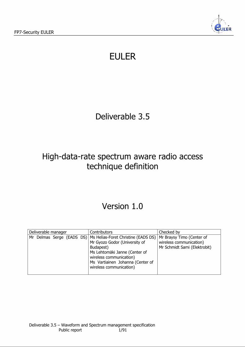
Figure 5: EULER PMR Mobile Broadband systems interconnection
Thanks to the Relay Station interconnection terminal, the both Relay Stations A and B may exchange data. The wireless data transmission may initiate either by the Relay Station A or the Relay Station B : the radio connection via the RS interconnection terminal is bidirectional.
A Relay Station interconnection terminal has the same properties than an EULER Mobile Station except it is not assigned to a subscriber. Because, a Mobile Station registers to a unique Relay Station, a Relay Station interconnection terminal supports only one radio connection with a Relay Station.
A Relay Station may support several Relay Station interconnection terminals and so may request each of them to register to a different Relay Station.
A Relay Station may access a Relay Station, via its Relay Station interconnection terminal registered to the Relay Station, it wants to reach, or via the Relay Station interconnection terminals, wired connected to the Relay Station it wants to reach, and registered to it.
Via these wireless accesses, each Relay Station may send information to its directly accessible Relay Stations and may forward information received from one directly accessible Relay Station to one or
several directly accessible Relay Stations.
6.4.2 Information exchanged between EULER PMR Mobile Broadband systems
To provide user applications to the network subscribers, as in any wireless network, Relay Stations will exchange information, as for example, Mobile Stations locations, Servers locations, Relay Stations
connections, … A solution to point out to each Relay Station to which a Mobile Station is registered or where a server is located and so to avoid to loose time at a communication establishment, is to broadcast all the
devices (Mobile Stations and servers) locations to all the interconnected Relay Stations within the network. So, when a Mobile Station registers to a Relay Station or periodically, the Relay Station may warn all
the Relay Stations within the EULER PMR Mobile Broadband network of the new location of the Mobile Station. For that, it sends a Relay Station information message containing, at least, a dating, the Relay Station
identifier and the list of all the Mobile Station registered to it, or the difference with the previous sent list to all its directly accessible Relay Stations via Relay Station interconnection terminals.

FP7-Security EULER
Deliverable 3.5 – Waveform and Spectrum management specification Public report 18/91
Upon reception of a Relay Station information message, a Relay Station shall read the dating. If the message is previous to the last received Relay Station information message for that Relay Station or
has already been received, the message is discarded. Otherwise, the receiving Relay Station modifies its tables according to the message contain and transfers the Relay Station information message to its directly accessible Relay Stations, which were not previous destinations of the message.
So, each Relay Station exactly knows to which relay Station is registered each Mobile Station. Moreover, the previous Relay Station to which the Mobile Station was registered, shall remove the Mobile Station from its tables.
Since each EULER Relay Station keeps track of each Mobile Station location, a Mobile Station may be reached anywhere in the EULER PMR Mobile Broadband network.
Moreover, the Relay Stations may exchange supplementary information to apply any management and control functions, as for example handover, or paging of a broadband standard as LTE or WiMAX.
Furthermore, the Relay Stations may send supplementary information to help the radio spectrum sharing. Because the Radio blocks allocation is done for several frames, a Relay Station may warn its
closest Relay Stations and so its most interfering Relay Stations, the list of the Radio Blocks, it has allocated and the duration of each allocation. The receiving Relay Stations may use these information when processing its radio block allocations.
6.5 EULER spectrum description Thanks to the observation of the spectrum utilization, wireless Relay Stations will be able to
coordinate spectrum usage among each other without information exchange. The sharing of radio resources is reliant upon a known radio resources definition and intermediate
nodes synchronization.
6.5.1 EULER radio element definition A radio element is the smallest indivisible part in the spectrum, defined by a set of frequencies and a fixed duration (see Figure 6).
6.5.2 EULER radio block definition A radio block is a structured data sequence, matching to the smallest radio resource which can be allocated.
It can be drawn by a rectangle of a fixed set of N consecutive radio elements in frequency to M consecutive radio elements in time (see Figure 6).
Figure 6: Radio block representation example
Frequency
Time
Radio block of NxM radio elements
Radio elements

FP7-Security EULER
Deliverable 3.5 – Waveform and Spectrum management specification Public report 19/91
6.5.3 EULER radio frame definition A radio block is a structured data sequence of a fixed duration Tframe (see Figure 7). A radio frame is composed of a fixed number of radio blocks. Each radio block shall be numbered in a
radio frame. So, a radio block shall be indexed to a logical number associated to the radio block in the radio frame and the radio frame number.
Figure 7: Radio frame representation example
6.6 Dynamic spectrum management The following mechanisms shall allow multiple Relay Stations in an EULER PMR Mobile Broadband
network to cooperate and, intelligently, share the same spectrum band in a distributed way. As seen in §6.5.3, the allowed spectrum can be divide in independent radio blocks. Each radio block contains an amount of radio resources. The radio frame notion permits to associate to a radio block a
time domain and so to associate to a radio block a periodicity. Each Relay Station may allocate in multiples of one radio block in a radio frame or periodically.
6.6.1 Radio block sensing Each Relay Station shall sense, when it can, the input power level associated to each radio block in the allowed spectrum.
In a FDD (Frequency Division Duplex) system, a Relay Station transmits and receives at the same time, so, the Relay Station, in current use, cannot measure itself the power transmitted by the other
entities of the system on frequencies on which it is transmitting. Some devices could help a Relay Station to sense the missing frequencies in the allowed spectrum. For example, a Mobile Station, close to the Relay Station may be dedicated to the Radio blocks measurement.
In a TDD (Time Division Duplex) system, a Relay Station can measure the power transmitted by the other elements of the system, when it is not transmitting. So, a Relay Station cannot sense all the radio blocks.
Time
Tframe
Frequency
Radio block j in radio frame i
Radio frame i
Allowed spectrum
Radio frame i-1 Radio frame i+1
Radio block j+1 in radio frame i
Radio block j in radio frame i+1
FP7-Security EULER
Deliverable 3.5 – Waveform and Spectrum management specification Public report 20/91
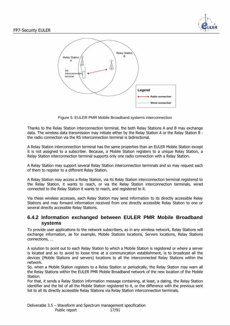
When a Relay Station cannot sense itself radio blocks, to obtain powers measurements, the Relay Station may use different solutions :
1. The Relay Station may suspend some user data transmissions, to do measurements. Before its transmission suspension, the Relay Station shall warn its neighboring Relay Stations of its intentions to avoid several neighboring Relay Station to apply the same transmission
suspension process at the same time. 2. As in a 802.22 network, the Relay Station may command some of its Mobile Stations to
measure received powers in radio blocks, in radio frames and to send it back to it.
Thanks to these sensing, each Relay Station in the EULER PMR Mobile Broadband network is able to associate a measured power to the radio block i, in the radio frame j : Pi, j.
6.6.2 Radio resource mapping By measuring the received power strength on all the allowed radio blocks, at a time, a Relay Station knows which allowed radio blocks are used and so which allowed radio blocks are unused. Therefore,
at a time, each Relay Station is able to establish a mapping of the used, unused and partly used radio resource, in the allowed spectrum bands.
Thanks to the power Pi,j, obtained by the radio block sensing (see §6.6.1), the Relay Station shall estimate the radio block occupancy rate :
• The Relay Station shall calculate over several radio frames, the average of the powers Pi,j
associated to the radio block : the mean power.
• A high mean power means that the radio block is very much used.
• A low mean power means that the radio block is very few used. • The Relay Station shall associate to each radio block an estimation to its occupancy rate.
So, a radio resource mapping is obtained. Moreover, to improve its own radio resource mapping, a Relay Station may ask its neighboring Relay
Stations in the EULER PMR Mobile Broadband network : • their radio resource mappings or • the radio resource they have allocated.
6.6.3 Radio resource allocation To allocate a radio resource to an application is to put an amount of radio blocks at the application's disposal for its user data transmission. The radio resource may be allocated, by a Relay Station for Mobile Stations use, for an uplink (from one Mobile Station to the Relay Station) or a downlink (from
the Relay Station to one or several Mobile Stations) transmission. To request radio resource, an application, located in the Relay Station or in a Mobile Station, sends at
least the following parameters to the Relay Station : 1. a transmit direction (uplink or downlink), 2. according to the transmit direction , the coordinates of the Mobile Stations involved in the
radio resource allocation : one Mobile Station (in uplink transmission), one or several Mobile
Stations (in downlink transmission), and 3. a Quality of Service (including at least, a throughput and a maximum allocation duration).
∑ Pi,j j = m to n
n-m+1
Pi =

FP7-Security EULER
Deliverable 3.5 – Waveform and Spectrum management specification Public report 21/91
According to the requested Quality of Service, the position of the involved Mobile Stations and the measured radio resource mapping, the Relay Station shall deduce the most appropriate modulation
and coding scheme between the sender and the receiver and the number of radio blocks to allocate to answer to the radio resource allocation request.
The number of radio blocks to allocate to answer to the radio resource allocation request can be greater than one : several radio blocks per radio frame are necessary to fulfill the demand or can be lower than one : the application needs only one radio block every x radio frames.
A radio resource allocation is specified by a set of radio block allocations (see Figure 8). In the example described Figure 8, the Relay Station has allocated :
• to the application 1, just one radio block : the radio block j, every two radio frames, starting radio frame i-1. The radio block allocation lasts T1 radio frames.
• to the application 2, two radio blocks.
• The first allocated radio block is the radio block k, it is allocated every radio frame and the allocation starts radio frame i. The radio block allocation lasts T2 radio frames.
• The second allocated radio block is the radio block l, it is allocated every radio frame and the allocation starts radio frame i. The radio block allocation lasts T2 radio frames.
Figure 8: Allocated radio resource representation example
To respond to one radio resource allocation request, the Relay Station may need to allocate several radio blocks. Each radio block allocation may be independent.
A Relay Station may accept or refuse a radio resource allocation request. The Relay Station shall respond to the requesting application. When the response is favorable, the Relay Station shall transmit the allocated radio blocks coordinates, according to the broadband standard procedures.
Allocated radio resources – Application 1 – Resource quantity = 1 radio block
Period = 1 radio frame over 2
Allocated radio resources – Application 2 – Resource quantity = 2 radio blocks
Period = every radio frame
Frequency
Time
Radio frame i Radio frame i+1 Radio frame i-1
j j j
l l l
kk k
Radio block
Allowed spectrum
Radio frame n
l
k
T1
T2
j

FP7-Security EULER
Deliverable 3.5 – Waveform and Spectrum management specification Public report 22/91
6.6.4 Radio block allocation A radio block allocation (see Figure 8) consists in allocating periodically (every x radio frames, where x can be equal to 1) the same logical radio block in a radio frame. The radio block logical index in the
radio frame shall be identical at each period. Radio blocks allocation shall be done in four steps :
1. the estimation of the occupancy rate, associated to each radio block,
2. the establishment of a list of radio blocks which are appropriate for the allocation, 3. the selection of the allocated radio blocks from the appropriate radio blocks list, 4. when according to the measured radio resource mapping, a selected radio bloc cannot be fully
used, the selection of the first allocated radio frame. Radio block occupancy rate estimation From the radio resource mappings (see §6.6.2) and, possibly, the information received from the other
Relay Stations or from Mobile Stations, the Relay Station shall associate to each Radio Block an occupancy rate :
• A very much used radio block has a high radio block occupancy rate.
• A very few used radio block has a low radio block occupancy rate.
Establishment of the appropriate radio blocks list To allocate radio blocks, first, the Relay Station shall establish a list of radio blocks which can be totally or partly used for the allocation : the appropriate radio blocks list.
1. The Relay Station may use radio resource already partly allocated by it : some radio frames of a radio block are allocated to one application, the unused radio frames may be allocated by the Relay Station to another application.
2. Or, the Relay Station may select new radio blocks in the allowed spectrum. According to the radio block allocation request, the Relay Station shall establish a list of radio blocks available to radio block allocation according to the spectrum management policy rules (for example, an
entity cannot transmit and receive at the same time, …). Thanks to an occupancy threshold (T_occ), the Relay Station shall select radio blocks. The occupancy threshold (T_occ) may take several values in order to optimize the radio blocks occupancy. When according to a too restrictive occupancy threshold (T_occ), the number of radio blocks in the list is not sufficient,
the Relay Station may increase the occupancy threshold (T_occ) to obtain a new list. When the appropriate radio blocks list does not contain enough unused or partly unused radio blocks,
to respond fully to the radio block allocation, the Relay Station shall refuse the radio resource allocation request. The appropriate radio blocks list shall be composed of radio blocks which shall be appropriate
according to the radio resource allocation request. Each radio block in the list is associated to an occupancy rate and so to a radio frame periodicity.
FP7-Security EULER
Deliverable 3.5 – Waveform and Spectrum management specification Public report 23/91
Radio blocks selection Secondly, when there are enough unused or partly unused radio blocks, to respond fully to the radio
resource allocation request, the Relay Station shall select from the appropriate radio blocks list, the allocated radio blocks, thanks to iterative stages :
step 1. The allocated radio blocks list is empty.
step 2. The Relay Station shall draw from the list of the appropriate radio blocks a random number.
step 3. The Relay Station shall claim the radio block pointed out by the random number allocated to the radio resource allocation request : the new allocated radio block.
step 4. The Relay Station shall introduce the new allocated radio block to the allocated radio blocks list. The Relay Station shall calculate the radio resource quantity brought by the new allocated radio block, according to its associated radio frame periodicity, and shall
compare it to the requested radio resource quantity. step 5. While the radio resource quantity allocated to the radio resource allocation request is
lower than the requested radio resource quantity, the Relay Station shall select a new
radio block and so go back to step 2. Otherwise, when the allocated radio resource quantity is greater or equal to the requested radio resource quantity, the Relay Station shall select for each allocated radio block, the first allocated radio frame.
Radio frame selection Once a radio block has been allocated, the Relay Station has to select the first radio frame in which
the radio block shall be allocated : • When the claimed radio block is measured as unused, the Relay Station shall start its radio
block allocation in any radio frame.
• When the claimed radio block is measured as partly used, the Relay Station may choose the first radio frame in which the radio block shall be allocated :
o via a random number or
o by looking at the measured powers of the radio block in the previous radio frames and trying to guess the index of the next radio frame in which the radio block is unused.
The following radio frame, in which the radio block shall be allocated, shall be calculated according to the radio block allocation periodicity. The radio frame selection must be done for each radio block in the allocated radio blocks list.
Thanks to broadband standard rules, the Relay Station shall address to each requested application the coordinates (radio block index, radio frame index) of its allocated radio blocks.

FP7-Security EULER
Deliverable 3.5 – Waveform and Spectrum management specification Public report 24/91
6.6.5 Flow-chart of a dynamic spectrum management algorithm The flow-chart of a dynamic spectrum management algorithm is shown Figure 9.
Is the number of free RB enough to provide the
Radio resource allocation request ?
Computation of the requested Radio Blocks and the Radio Block Allocation Periodicity
according to the requested QoS and the radio conditions
No Yes
Estimation of the occupancy rate of each radio block in the radio frame according to the
current Relay Station information
Measurements done by the current
Relay Station
Measurements done by Mobile
Stations
Information sent by the neighboring
Relay Stations
Radio resource allocation request
Radio resource allocation refusal
Radio resource allocation
acknowledgement
Selection of one Radio Block in the radio frame
Selection of the first selected radio frame in the selected Radio Block
Is the number of selected Radio Blocks sufficient to acknowledge the Radio resource allocation ?
Is there at least one RB available for the Radio resource allocation ?
Yes
Yes
No No
Is the Radio Block Allocation Periodicity compatible with the
selected Radio Block ?
Yes
No
Computation of the remaining Radio Blocks to select
Figure 9: Flow-chart of a dynamic spectrum management algorithm
7 Specification of corresponding Application Programming Interfaces (API)
The following application programming interfaces enable to integrate EULER functionalities to existing broadband networks. An overview of the interactions between the added EULER functionalities and a broadband network is given Figure 10.

FP7-Security EULER
Deliverable 3.5 – Waveform and Spectrum management specification Public report 25/91
Figure 10: Interfaces overview between the EULER functionalities and a broadband network
7.1 EULER Radio blocks occupancy map factory The EULER radio blocks occupancy map factory is located in the Relay Station.
The EULER radio blocks occupancy map factory dynamically provides a mapping of the occupancy rate of the radio resources use, at a given time, over the air interface.
The radio blocks occupancy map calculation is based on information coming from various sources :
• information contained in the Relay Station,
• information coming from the Mobile Stations registered to the Relay Station, • information coming from the neighboring Relay Stations, including those carrying legacy X2
eNode interface for LTE or by R8 interface for WiMAX. The output of the radio blocks occupancy mapping algorithm is a use probability linked to each radio
resource. The radio blocks occupancy mapping shall be used by the EULER scheduler to determine which radio resources it may use to transmit information. All information needed by the radio blocks occupancy map factory is passed via functions defined in
the radio blocks occupancy map factory interface (see Figure 11, Figure 12 and Figure 13).
Figure 11: EULER radio blocks occupancy map factory interfaces
EULER radio blocks occupancy map factory
Relay Station Configuration
Radio blocks measurements coming from mobile stations
Radio blocks measurements coming from the relay station
Clock
Neighboring Relay Stations
information
Radio blocks occupancy mapping
EULER radio blocks occupancy map factory
Radio blocks measurements
EULER Scheduler
EULER radio blocks measurement scheduler
Radio blocks occupancy mapping
Broadband network
Radio Blocks measurements
scheduling
Scheduler persistent allocations
Neighboring information
Radio resource request
RACH, Link Control, HARQ, UL, DL contents
DL and UL sub-frames assignment
Radio Blocks measurements
scheduling
Reset

FP7-Security EULER
Deliverable 3.5 – Waveform and Spectrum management specification Public report 26/91
Figure 12: EULER radio blocks occupancy map factory input interfaces
Figure 13: EULER radio blocks occupancy map factory interface output functions
7.2 EULER radio block measurement scheduler The EULER radio block measurement scheduler is located in the Relay Station.
The EULER radio block measurement scheduler dynamically schedules the radio blocks to measure, at a given time.
The measuring decisions are based on information coming from various sources :
• information contained in the Relay Station,
• information coming from the Mobile Stations registered to the Relay Station.
The output of the radio block measurement scheduler algorithm is the scheduling of the radio block measurement in the relay station and eventually in some mobile stations. All information needed by the radio block measurement scheduler is passed via functions defined in
the radio block measurement planner interface (see Figure 14, Figure 15 and Figure 16).
Figure 14: EULER radio block measurement scheduler interfaces
Input Function Description
MapReset Resets the EULER radio blocks occupancy map factory to its initial state.
MapRelayStationConfiguration Processes the Relay Station specific configuration :
• frame configuration (as for example, configuration, synchronization parameters), …
MapRelayStationRBMeas Processes the radio block measurements coming from the relay station.
MapMobileStationRBMeas Processes the radio block measurements coming from a mobile station.
MapNeighboringStationRB Processes the radio block use coming from the neighboring relay stations.
MapNextMapping Triggers the generation of the next mapping.
Output Function Description
MapRadioBlocksMapping The EULER radio blocks map occupancy factory sends a mapping of the radio blocks occupancy rate.
EULER radio blocks measurement
scheduler
Relay Station Configuration Mobile Station Measurements scheduling
Scheduler persistent allocations Radio Blocks measurements
scheduling in the Relay Station
Mobile Stations Setup/Removal
Clock
Reset

FP7-Security EULER
Deliverable 3.5 – Waveform and Spectrum management specification Public report 27/91
Figure 15: EULER radio block measurement scheduler input functions
Figure 16: EULER radio block measurement scheduler output functions
Input Function Description
MeaReset Resets the EULER radio block measurement scheduler to its initial state.
MeaRelayStationConfiguration Processes the Relay Station specific configuration :
• frame configuration (as for example, configuration, synchronization parameters, RACH location and period, Paging period),
• the radio block measurement configuration associated to the Relay Station (no radio block measurement, measurement only
on unused radio block, periodic radio block measurement, …), • the radio block measurement configuration associated to the
Mobile Stations registered to the Relay Station (no radio block
measurement, periodic radio block measurement, …), …
MeaMobileStationSetUp Processes the Mobile Stations setup or modification. The EULER radio block measurement scheduler stores, for each
Mobile Station registered to the Relay Station, information as : • the timing advance associated to the Mobile Station, • its availability (loads, declared presence in the network),
• its already scheduled measurements (gaps/periods, …)
MeaMobileStationRemoval Removes all the context within the EULER radio block
measurements scheduler related to the Mobile Station.
MeaPersistentRBAllocation Processes the UL and DL persistent radio block allocations to Mobile Stations.
MeaNextFrame Triggers the generation of the next radio block measurements scheduling.
Output Function Description
MeaRelayStationPlanning The EULER radio block measurements scheduler sends the list of the
Radio Blocks, the relay station shall measure next frame. The list may point out specific radio blocks and/or may indicate to select the unused DL radio blocks.
MeaMobileStationPlanning The EULER radio block measurements scheduler sends a list of mobile stations which shall provide measurements on specific Radio Blocks and their associated configuration.

FP7-Security EULER
Deliverable 3.5 – Waveform and Spectrum management specification Public report 28/91
7.3 EULER radio block allocation scheduler The EULER radio block allocation scheduler is located in the Relay Station.
The EULER radio block allocation scheduler dynamically allocates uplink and downlink radio resources, at a given time, over the air interface.
The EULER radio block allocation scheduler assigns radio resources to satisfy applications requirements, with as few as possible interferences with other Relay Stations radio resource
allocations. The scheduling decisions are based on information coming from various sources :
• information contained in the Relay Station,
• information coming from the Mobile Stations registered to the Relay Station.
The outputs of the scheduling algorithm are : • a scheduling assignment per uplink and downlink sub-frames and • persistent radio blocks allocation to Mobile Stations.
The output "Persistent radio blocks allocation to Mobile Stations" ensures the scheduling of the radio
blocks measurements by Mobile Stations. All information needed by the scheduler is passed via functions defined in the Scheduler interface (see Figure 17, Figure 18 and Figure 19).
Figure 17: EULER radio block allocation scheduler interfaces
EULER radio block allocation scheduler
Relay Station Configuration HARQ information
Scheduler frame assignments
Radio Resource Allocation requests
Random access Mobile Stations Setup/Removal
Link Control information
Radio blocks occupancy mapping
DL and UL Buffers contents
Clock Scheduler persistent allocations
Radio blocks measurement configuration
Reset

FP7-Security EULER
Deliverable 3.5 – Waveform and Spectrum management specification Public report 29/91
Figure 18: EULER radio block allocation scheduler interface input functions
Input Function Description
SchReset Resets the EULER radio block allocation scheduler to its initial
state.
SchRelayStationConfiguration Processes the Relay Station specific configuration : • frame configuration (as for example, configuration,
synchronization parameters, RACH location and period, Paging period),
• Broadcast information,
• Available user services, …
SchMobileStationSetUp Processes the Mobile Stations setup or modification. The EULER radio block allocation scheduler stores, for each Mobile Station registered to the Relay Station, information as : • the minimum Modulation and Coding Scheme to associate to
the Mobile Station, • its associated identifiers, …
SchMobileStationRemoval Removes all the context within the EULER radio block allocation scheduler related to the Mobile Station.
SchMobileStationMeasurement Informs the EULER radio block allocation scheduler a change in
Mobile Station measurements as timing measurement, or downlink channel conditions.
SchRelayStationRBMeasurement Informs the EULER radio block allocation scheduler the radio
blocks to measure by the Relay Station in the next frame.
SchMobileStationRBMeasurement Processes the Radio Block measurement setup or modification in the Mobile Stations (radio blocks measurement gaps/periods, …)
SchRadioBlocksMapping Informs the EULER radio block allocation scheduler of the mapping of the radio Blocks occupancy rate.
SchRadioBearerSetUp Establishes or modifies a radio bearer related to a Mobile Station
and stores the configuration parameters as for example : • the QoS, • the radio bearer identifier,
• the Modulation and Coding Scheme, • the transmitting power, …
SchRadioBearerSuspension Suspends a radio bearer related to a Mobile Station upon command from higher layers (radio link failure or handover)
SchRadioBearerRemoval Removes a radio bearer.
SchRACHResp Informs the EULER radio block allocation scheduler that a Random Access Response is required. Moreover, the EULER scheduler
allocates UL resource for the Mobile Stations connection requests.
SchDlBuffer Informs the EULER radio block allocation scheduler that DL buffers have data (user data, control data and UL message
acknowledgement) to send.
SchStatusReport Informs the EULER radio block allocation scheduler that a Buffer Status Report must be scheduled for a Mobile Station.
SchDlRetransmission Informs the EULER radio block allocation scheduler than a DL retransmission is required
SchUlSchedulingReq Informs the EULER radio block allocation scheduler that a
Scheduling Request (SR) has been received from a Mobile Station.
SchUlRetransmission Informs the EULER radio block allocation scheduler than an UL retransmission is required.
SchNextFrame Triggers the generation of the next frame.

FP7-Security EULER
Deliverable 3.5 – Waveform and Spectrum management specification Public report 30/91
Figure 19: EULER radio block allocation scheduler interface output functions
7.4 Data description of the radio blocks occupancy mapping Slots positioned in time and frequency constitute a radio frame. A radio block within a frame is defined
by sub-channel and symbol dimension as seen in §6.5.3. The format frame depends on the chosen broadband standard : WiMAX or LTE.
A radio blocks occupancy mapping is a set of maps describing the use of the radio blocks in the N previous radio frames, seen from the Relay Station.
The number of radio blocks occupancy maps, N, is set by configuration. Each radio block in each map is associated to a numeric value : the occupancy rate,
• When the occupancy rate is equal to zero, the associated radio block is considered not occupied.
• When the occupancy rate is equal to infinity, the associated radio block is considered fully occupied.
The N radio blocks occupancy maps should be computed, by the EULER radio blocks map occupancy factory, in each Relay Station thanks to measured data and, optionally, information coming from neighboring Relay Stations :
• when a Radio Block is allocated by a neighboring relay station, the associated occupancy rate
values are set to infinity, • when no measurement for a Radio Block is available, the associated occupancy rate values
are set to infinity, • otherwise, the occupancy rate value is calculated thanks to the radio electric measurements
(done by the Relay Station and Mobile Stations). Moreover, the EULER radio blocks map occupancy factory may deduce from the N radio blocks occupancy maps a unique map, given per each radio block a occupancy probability for the next frame.
The radio blocks occupancy mapping shall be transmitted to the EULER Scheduler.
8 Application of the EULER network to existing broadband networks
This chapter highlights the issues and functionalities of IEEE 802.16m and LTE technologies that are applicable to waveform and spectrum utilization of an EULER PMR Mobile Broadband network
specification.
8.1 Applicability of the EULER network to IEEE 802.16m network
In this section we present the main functionalities of IEEE 802.16m that comply with the EULER waveform and spectrum definition presented in section 6. The scope of this section is to assess the system aspects of IEEE 802.16m and validate the applicability to EULER network.
Output Function Description
SchFrameAssignment Upon reception of the next frame generation request, the EULER radio block allocation scheduler sends the DL and UL sub-frames assignment.
FP7-Security EULER
Deliverable 3.5 – Waveform and Spectrum management specification Public report 31/91
8.1.1 IEEE 802.16m frame structure
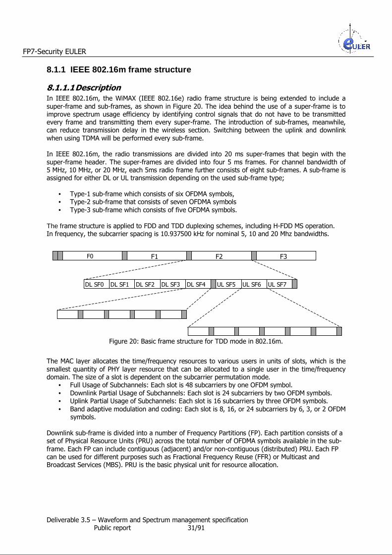
8.1.1.1 Description In IEEE 802.16m, the WiMAX (IEEE 802.16e) radio frame structure is being extended to include a
super-frame and sub-frames, as shown in Figure 20. The idea behind the use of a super-frame is to improve spectrum usage efficiency by identifying control signals that do not have to be transmitted every frame and transmitting them every super-frame. The introduction of sub-frames, meanwhile, can reduce transmission delay in the wireless section. Switching between the uplink and downlink
when using TDMA will be performed every sub-frame. In IEEE 802.16m, the radio transmissions are divided into 20 ms super-frames that begin with the
super-frame header. The super-frames are divided into four 5 ms frames. For channel bandwidth of 5 MHz, 10 MHz, or 20 MHz, each 5ms radio frame further consists of eight sub-frames. A sub-frame is assigned for either DL or UL transmission depending on the used sub-frame type;
• Type-1 sub-frame which consists of six OFDMA symbols, • Type-2 sub-frame that consists of seven OFDMA symbols
• Type-3 sub-frame which consists of five OFDMA symbols.
The frame structure is applied to FDD and TDD duplexing schemes, including H-FDD MS operation. In frequency, the subcarrier spacing is 10.937500 kHz for nominal 5, 10 and 20 Mhz bandwidths.
Figure 20: Basic frame structure for TDD mode in 802.16m.
The MAC layer allocates the time/frequency resources to various users in units of slots, which is the
smallest quantity of PHY layer resource that can be allocated to a single user in the time/frequency domain. The size of a slot is dependent on the subcarrier permutation mode.
• Full Usage of Subchannels: Each slot is 48 subcarriers by one OFDM symbol.
• Downlink Partial Usage of Subchannels: Each slot is 24 subcarriers by two OFDM symbols. • Uplink Partial Usage of Subchannels: Each slot is 16 subcarriers by three OFDM symbols.
• Band adaptive modulation and coding: Each slot is 8, 16, or 24 subcarriers by 6, 3, or 2 OFDM symbols.
Downlink sub-frame is divided into a number of Frequency Partitions (FP). Each partition consists of a set of Physical Resource Units (PRU) across the total number of OFDMA symbols available in the sub-
frame. Each FP can include contiguous (adjacent) and/or non-contiguous (distributed) PRU. Each FP can be used for different purposes such as Fractional Frequency Reuse (FFR) or Multicast and Broadcast Services (MBS). PRU is the basic physical unit for resource allocation.
F0 F1 F2 F3
DL SF0 DL SF1 DL SF2 DL SF3 DL SF4 UL SF5 UL SF6 UL SF7

FP7-Security EULER
Deliverable 3.5 – Waveform and Spectrum management specification Public report 32/91
The logical resource allocation definition for IEEE 802.16m in terms of OFDMA subcarriers is presented in Figure 21. The Resource Unit (RU) consists of 108 modulation symbols, 18 subcarriers over 6 OFDM
symbols in UL sub-frame. Each UL RU is divided into 3 tiles, which contains 6 contiguous subcarriers by 6 OFDM symbols. UL DRU includes 3 distributed tiles over whole frequency band. UL logical RU includes 3 adjacent tiles in frequency domain.
Figure 21: Resource allocation for Uplink TDD in 802.16m.
8.1.1.2 Adaptability to EULER system The IEEE 802.16m frame structure and the EULER frame structure can be considered to be
compatible. The naming and scope of the terms are little different but in overall the definitions comply with one another.
The resources in IEEE 802.16m for uplink and downlink transmissions are defined with different sub-frames and EULER system utilizing 802.16m may choose the best uplink-downlink configuration according to its needs. No common uplink-downlink configuration between the EULER systems sharing a spectrum band is necessary. Frame alignment feature for coexistence support in frame structure is
also applicable for multiple EULER system existence.
8.1.2 IEEE 802.16m synchronization and system information broadcast The Advanced Preamble (A-Preamble) is a DL physical channel which provides a reference signal for timing, frequency, and frame synchronization, RSSI estimation, channel estimation, and Advanced Base Station (ABS) identification. The A-Preamble consists of Primary Advanced Preamble (PA-
Preamble) and Secondary Advanced Preamble (SA-Preamble). As show in Figure 22. PA-Preamble is located at the first symbol of second frame in a super-frame. SA-Preamble is located at the first symbol of remaining three frames of the DL transmission.
tile
Frequency
Time

FP7-Security EULER
Deliverable 3.5 – Waveform and Spectrum management specification Public report 33/91
Figure 22: Structure of the A-Preamble.
The PA-Preamble has these properties: • Common to a group of sectors/cells
• Supports limited signaling (e.g., system bandwidth, carrier information, etc.) • Fixed number of subcarriers ( but the occupied bandwidth is less than 5MHz)
The SA-Preamble has these properties:
• Full bandwidth
• Carries cell ID information
The A-Preamble sequences are designed so that timing synchronization by autocorrelation can be done with maximum efficiency. The power of these signals can also be boosted. Frequency reuse of 1 is used for PA-Preamble and frequency reuse of 3 is used for SA-Preamble.
8.1.2.1 Adaptability to EULER system
To enter in an EULER network, a Relay Station listens to the allocated spectrum bands to listen the
synchronization signals emitted by the EULER systems already present in the network. Then, the new entry system chooses a free allocated spectrum band and starts emitting its synchronization signals. A frequency band is reserved in IEEE 802.16m for synchronization signals. In an EULER network,
several synchronization signals based on IEEE 802.16m and each associated to coexisting EULER networks can be formed and sent according to the procedures described in Section 8.2.2. In IEEE 802.16m the locations for synchronization signals reside in the super-frame or sub-frame headers
depending on the scope of the synchronization.
8.1.3 Mobile station initialization and registration The Advanced Mobile Station (AMS) in IEEE 802.16m has multiple states as in any communication system including mobile terminals. The state transition diagrame of AMS is presented in Figure 23.
Figure 23: IEEE 802.16m Mobile Station State Transition Diagram.

FP7-Security EULER
Deliverable 3.5 – Waveform and Spectrum management specification Public report 34/91
In the Initialization State, the AMS performs cell selection by scanning, synchronizing and acquiring the system configuration information before entering Access State. During this state, if the AMS
cannot properly perform the system configuration information decoding and cell selection, it falls back to perform scanning and DL synchronization. If the AMS successfully decodes the system configuration information and selects a target Advanced Base Station (ABS), it transitions to the
Access State. The AMS performs network entry with the target ABS while in the Access State. Network entry is a multi step process consisting of ranging, basic capability negotiation, authentication, authorization,
key registration with the ABS and service flow establishment. The AMS receives its Station ID and establishes at least one connection using and transitions to the Connected State. Upon failing to complete any one of the steps of network entry the AMS transitions to the Initialization State.
When in the Connected State, an AMS operates in one of three modes; Sleep Mode, Active Mode and Scanning Mode. During Connected State, the AMS maintains two connections established during
Access State. Additionally, the AMS and the ABS may establish additional transport connections. The AMS may remain in Connected State during a hand over. The AMS transitions from the Connected State to the Idle State based on a command from the ABS. Failure to maintain the connections prompts the AMS to transition to the Initialization State.
The Idle state consists of two separated modes, Paging Available Mode and Paging Unavailable Mode based on its operation and MAC message generation. During Idle State, the AMS may perform power
saving by switching between Paging Available Mode and Paging Unavailable Mode.
8.1.3.1 Adaptability to EULER system
An EULER network is constituted of several emitting EULER systems sharing the same broadband spectrum.
When a mobile station wants to register to the EULER network, the mobile station first scans the allowed spectrum bands, according to its configuration and searches for a system in the EULER network that it wants to register.
The Advanced Preamble synchronization signals with the location known by the mobile station is the key element for the synchronization process.
The IEEE 802.16m mechanisms associated to the mobile station registration may be applied to a EULER network without any major standard changes.
8.1.4 Radio resources management in IEEE 802.16m The Radio Resource Management in IEEE 802.16m adjusts radio network parameters based on traffic load, and also includes function of load control (load balancing), admission control and interference
control.
8.1.4.1 Downlink control channels
DL control channels are needed to convey information essential for system operation. In order to reduce the overhead and network entry latency, and improve robustness of the DL control channel, information is transmitted hierarchically over different time scales from the super-frame level to the
sub-frame level. Broadly speaking, control information related to system parameters and system configuration is transmitted at the super-frame level, while control and signaling related to traffic transmission and reception is transmitted at the frame/sub-frame level.
Super-Frame Header (SFH) is a control information conveying channel for IEEE 802.16m control traffic. The location of the SHF is naturally located in the beginning of each 20ms super-frame and at the beginning of the first sub-frame in that particular super-frame. The Super-Frame Header (SFH)

FP7-Security EULER
Deliverable 3.5 – Waveform and Spectrum management specification Public report 35/91
carries essential system parameters and system configuration information. The SFH is divided into two parts: Primary Super-Frame Header (P-SFH) and Secondary Super-Frame Header (S-SFH). The P-SFH
and S-SFH are transmitted using predetermined modulation and coding schemes to ease the overall demodulation and decoding process.
Essential system parameters and system configuration information carried in the S-SFH is categorized into three subpacket information elements (IE). The S-SFH Sub-Packet 1 (SP1) IE includes information needed for network re-entry. S-SFH SP2 contains information for initial network entry and network discovery. S-SFH SP3 contains remaining essential system information.
Advanced Medium Access Protocol (A-MAP) is utilized for Message-Based Control and Signaling. This unicast service control information consists of both user-specific and non-user-specific control
information. User-specific control information is further divided into assignment information, HARQ feedback
information, and power control information, and they are transmitted in the assignment A-MAP, HARQ feedback A-MAP, and power control A-MAP, respectively. Non-user-specific control information includes information required to decode the user-specific control.
Non-user specific control information that is not carried in the SFH may be included in this category. The Minimum Logical Resource Unit (MLRU) in the assignment A-MAP consists of 56 data tones. All
the A-MAPs share a region of physical resources called A-MAP region. The first IEEE 802.16m DL sub-frame of each frame contains at least one A-MAP region. An A-MAP region can include both non-user specific and user specific control information. A-MAP regions are located in every DL sub-frame. DL and UL resource assignments in an A-MAP region follow a pre-defined rule to determine the
corresponding DL and UL sub-frames in which the resources are assigned.
Information Channel Location in a frame
Synchronization information A-Preamble: PA-Preamble and SA-Preammble
PA-Preamble is located at the first symbol of second frame in a super-frame. SA-Preamble is
located at the first symbol of remaining three frames.
System configuration
information
Primary Super-Frame Header
(P-SFH) and Secondary Super-Frame Header (S-SFH)
Inside SFH
Extended system parameters
and system configuration information
Additional Broadcast
Information on Traffic Channel
Outside SFH
Control and signaling for DL Notifications
Additional Broadcast Information on Traffic Channel
Outside SFH
Control and signaling for traffic Advanced MAP Outside SFH
Figure 24: IEEE 802.16m DL control information channel allocation.
8.1.4.2 Uplink control channels The UL control channels carry multiple types of control information to support air interface
procedures. The UL sub-frame size for transmission of control information is 6 symbols. The UL control channels are:
• Uplink Fast Feedback Channel
• Uplink HARQ Feedback Channel • Uplink Sounding Channel • Ranging Channel • Bandwidth Request Channel

FP7-Security EULER
Deliverable 3.5 – Waveform and Spectrum management specification Public report 36/91
Uplink control information can be multiplexed with data on the UL data channels as MAC headers or MAC control messages. Inband control signaling can contain information such as uplink bandwidth requests or bandwidth assignment updates. The UL channel info is summarized in
Information Channel
Channel quality feedback UL Fast Feedback Channel
UL Sounding Channel
MIMO feedback UL Fast Feedback Channel UL Sounding Channel
HARQ feedback UL HARQ Feedback Channel
Synchronization UL Ranging Channel
Bandwidth request Bandwidth Request Channel
UL Inband Control Signaling UL Fast Feedback Channel
E-MBS feedback Common E-MBS Feedback Channel
Figure 25: IEEE 802.16m UL control information channel allocation.
8.1.4.3 Other IEEE 802.16m functions
The IEEE 802.16m standard provides other useful functions to develop an EULER network such as: • Power control
o The power control scheme is supported for DL and UL based on the frame structure, DL/UL control structures, and Fractional Frequency Reuse (FFR).
• Channel Quality Feedback
• Support for Relay networking o Relaying is performed using a decode and forward paradigm. The Advanced Base
Stations and Advanced Relay Stations deployed within a sector operate using either time division duplexing or frequency division duplexing of DL and UL transmissions. An Advanced Relay Station operates in time-division transmit and receive relaying mode.
8.1.4.4 Compatibility with EULER system
As specified in an EULER network, a IEEE 802.16m Base Station controls the downlink and uplink radio resources allocations in multiples of one resource block among the users at each time with the the appropriate control information requested by the EULER system.
The relaying option present in IEEE 802.16m is functional in EULER system.
8.1.5 Reference Signals Transmission of pilot subcarriers in the DL is required to enable channel estimation, channel quality measurement, frequency offset estimation, and so on. IEEE 802.16m supports both common and dedicated pilot structures. The dedicated pilots are associated with a specific Fractional-Frequency-
Reuse (FFR) group and can be used only by the mobile stations assigned to that group; therefore, they can be precoded or beamformed similarly to the data subcarriers. The pilot structure is defined for up to eight transmission streams, and there is a unified design for common and dedicated pilots.
Pilot structures for different data streams for both up and downlink are demonstrated in Figure 26.
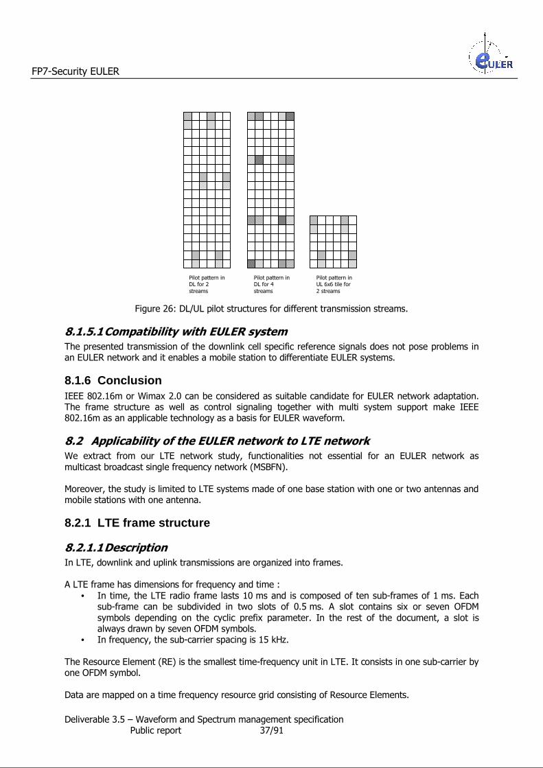
FP7-Security EULER
Deliverable 3.5 – Waveform and Spectrum management specification Public report 37/91
Figure 26: DL/UL pilot structures for different transmission streams.
8.1.5.1 Compatibility with EULER system
The presented transmission of the downlink cell specific reference signals does not pose problems in an EULER network and it enables a mobile station to differentiate EULER systems.
8.1.6 Conclusion IEEE 802.16m or Wimax 2.0 can be considered as suitable candidate for EULER network adaptation. The frame structure as well as control signaling together with multi system support make IEEE 802.16m as an applicable technology as a basis for EULER waveform.
8.2 Applicability of the EULER network to LTE network
We extract from our LTE network study, functionalities not essential for an EULER network as
multicast broadcast single frequency network (MSBFN). Moreover, the study is limited to LTE systems made of one base station with one or two antennas and mobile stations with one antenna.
8.2.1 LTE frame structure
8.2.1.1 Description
In LTE, downlink and uplink transmissions are organized into frames. A LTE frame has dimensions for frequency and time :
• In time, the LTE radio frame lasts 10 ms and is composed of ten sub-frames of 1 ms. Each sub-frame can be subdivided in two slots of 0.5 ms. A slot contains six or seven OFDM
symbols depending on the cyclic prefix parameter. In the rest of the document, a slot is always drawn by seven OFDM symbols.
• In frequency, the sub-carrier spacing is 15 kHz.
The Resource Element (RE) is the smallest time-frequency unit in LTE. It consists in one sub-carrier by one OFDM symbol.
Data are mapped on a time frequency resource grid consisting of Resource Elements.
Pilot pattern in DL for 2
streams
Pilot pattern in DL for 4
streams
Pilot pattern in UL 6x6 tile for
2 streams

FP7-Security EULER
Deliverable 3.5 – Waveform and Spectrum management specification Public report 38/91
The Resource Block (RB) is the downlink and uplink LTE transmission unit. It consists in one slot by 12
sub-carriers (180 kHz).
Figure 27: Radio resource representation in LTE
According to its allocated bandwidth, a LTE system shall be composed, in frequency, of 6 to 100
Resource Blocks. So, a radio frame shall be composed of 120 to 2 000 Resource Blocks. TDD particularity
In TDD, several uplink-downlink configurations are supported (see Figure 28).
Sub-frame number Uplink-downlink configuration
Downlink-to-Uplink Switch-point periodicity 0 1 2 3 4 5 6 7 8 9
0 5 ms D S U U U D S U U U 1 5 ms D S U U D D S U U D 2 5 ms D S U D D D S U D D 3 10 ms D S U U U D D D D D 4 10 ms D S U U D D D D D D 5 10 ms D S U D D D D D D D 6 5 ms D S U U U D S U U D
where D : Sub-frame reserved for downlink transmission,
U : Sub-frame reserved for uplink transmission, S : Special sub-frame enabling a D to U switch point
Figure 28: Uplink-downlink configurations (extracted from [3])
Time
Frequency One sub frame
0 1 2 3 4
4 5
5 6
6
9 8 7
One radio frame
One slot (0.5 ms)
One Radio Block
One Radio Element
12 sub-carriers or 180 kHz

FP7-Security EULER
Deliverable 3.5 – Waveform and Spectrum management specification Public report 39/91
8.2.1.2 Compatibility with EULER system The LTE frame structure and the EULER frame structure are fully compatible :
EULER unit Equivalent LTE unit
Radio Block Resource Block
Radio Element Resource Element
Radio Frame Frame
In LTE-TDD, the uplink-downlink configuration "1" enables an equitable sharing between the uplink
and the downlink Resource blocks. Four Resource Blocks are available in both transmission directions. Nevertheless, each EULER system, based on the LTE-TDD standard and sharing a common bandwidth, may choose the best uplink-downlink configuration according to its needs. No common
uplink-downlink configuration between the EULER systems sharing a spectrum band is necessary.
8.2.2 LTE synchronization and system information broadcast
8.2.2.1 Description A dedicated Synchronization CHannel (SCH) enables, in LTE, the transmission of two synchronization signals, the primary synchronization signals (P-SCH) and the secondary synchronization signals (S-
SCH). Within the SCH, both synchronization sequences are embedded in the central 62 sub-carriers of two OFDM symbols per frame.
The location of the synchronization signals in a frame depends of the duplexing scheme (TDD or
FDD) :
• In FDD, the P-SCH is mapped to the last OFDM symbol in slots 0 and 10, the S-SCH is mapped to the previous OFDM symbol in the same slot.
• In TDD, the P-SCH is mapped to the third OFDM symbol in slots 2 and 12, the S-
SCH is mapped to the last OFDM symbol in slots 1 and 11.
The synchronization signals are used to synchronize in time and in frequency and to transmit network parameters as the cell group identification (504 unique physical cell identities are available), and the used duplexing scheme.
So, the downlink synchronization signals are transmitted on four OFDM symbols in the central 6 Resource Blocks.
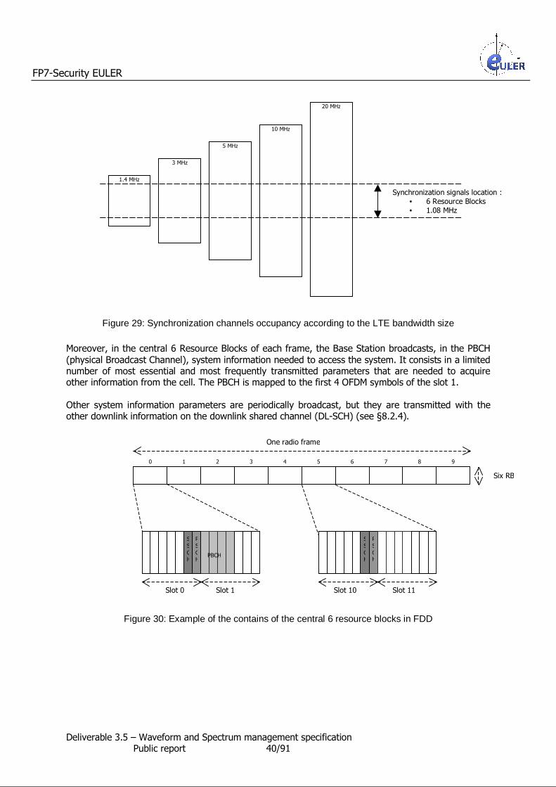
FP7-Security EULER
Deliverable 3.5 – Waveform and Spectrum management specification Public report 40/91
Figure 29: Synchronization channels occupancy according to the LTE bandwidth size
Moreover, in the central 6 Resource Blocks of each frame, the Base Station broadcasts, in the PBCH
(physical Broadcast Channel), system information needed to access the system. It consists in a limited number of most essential and most frequently transmitted parameters that are needed to acquire other information from the cell. The PBCH is mapped to the first 4 OFDM symbols of the slot 1.
Other system information parameters are periodically broadcast, but they are transmitted with the other downlink information on the downlink shared channel (DL-SCH) (see §8.2.4).
Figure 30: Example of the contains of the central 6 resource blocks in FDD
1.4 MHz
Synchronization signals location : • 6 Resource Blocks • 1.08 MHz
3 MHz
5 MHz
10 MHz
20 MHz
0 1 2 3 4 5 6 9 8 7
One radio frame
Slot 0 Slot 1 Slot 10 Slot 11
SS
CH
PBCH
PS
CH
SS
CH
PS
CH
Six RB
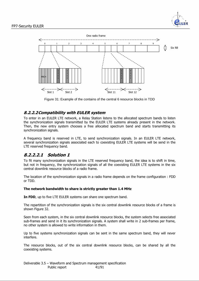
FP7-Security EULER
Deliverable 3.5 – Waveform and Spectrum management specification Public report 41/91
Figure 31: Example of the contains of the central 6 resource blocks in TDD
8.2.2.2 Compatibility with EULER system
To enter in an EULER LTE network, a Relay Station listens to the allocated spectrum bands to listen the synchronization signals transmitted by the EULER LTE systems already present in the network.
Then, the new entry system chooses a free allocated spectrum band and starts transmitting its synchronization signals.
A frequency band is reserved in LTE, to send synchronization signals. In an EULER LTE network, several synchronization signals associated each to coexisting EULER LTE systems will be send in the LTE reserved frequency band.
8.2.2.2.1 Solution 1 To fit many synchronization signals in the LTE reserved frequency band, the idea is to shift in time,
but not in frequency, the synchronization signals of all the coexisting EULER LTE systems in the six central downlink resource blocks of a radio frame. The location of the synchronization signals in a radio frame depends on the frame configuration : FDD
or TDD. The network bandwidth to share is strictly greater than 1.4 MHz
In FDD, up to five LTE EULER systems can share one spectrum band.
The repartition of the synchronization signals is the six central downlink resource blocks of a frame is shown Figure 32. Seen from each system, in the six central downlink resource blocks, the system selects free associated
sub-frames and send in it its synchronization signals. A system shall write in 2 sub-frames per frame, no other system is allowed to write information in them.
Up to five systems synchronization signals can be sent in the same spectrum band, they will never interfere. The resource blocks, out of the six central downlink resource blocks, can be shared by all the
coexisting systems.
0 1 2 3 4 5 6 9 8 7
One radio frame
PBCH
SS
CH
PS
CH
Slot 1 Slot 2
SS
CH
PS
CH
Slot 11 Slot 12
Six RB

FP7-Security EULER
Deliverable 3.5 – Waveform and Spectrum management specification Public report 42/91
The repartition of the synchronization signals is the whole bandwidth in a frame is shown Figure 33.
Figure 32: Example of the repartition of the synchronization signals in the six central downlink resource blocks, in a FDD radio frame shared by 5 coexisting LTE EULER systems
Figure 33: Example of the repartition of the 5 coexisting LTE EULER system synchronization signals in a FDD radio frame
In TDD, we choose to work with the uplink-downlink configuration "1" because, in that configuration the number of the D and U sub-frames are equal. But, another uplink-downlink configuration may be
used. In the uplink-downlink configuration "1", up to five LTE EULER systems can share one spectrum band. An example of repartition of the synchronization signals is the six central downlink resource blocks of
a frame is shown Figure 34.
P-SCH S-SCH PBCH
0 1 2 3 4 5 6 9 8 7
One radio frame
Six central RB
System 1
System 2
System 3
System 4
System 5
System 1
System 2
System 5
System 4
System 3
Downlink bandwidth
Resource blocks which can be used by any systems for the data transport
Resource blocks reserved to a system
Radio frame seen from the System 1
Radio frame seen from the System 2
Radio frame seen from the System 3
Radio frame seen from the System 4
Radio frame seen from the System 5
Sub-frame, never used by the system
The same six
central downlink blocks, seen from the
different systems of the network
0 1 2 3 4 5 6 9 8 7
One radio frame

FP7-Security EULER
Deliverable 3.5 – Waveform and Spectrum management specification Public report 43/91
Seen from each system, in the six central downlink resource blocks, the system selects free associated sub-frames and send in it its synchronization signals. A system shall write in four sub-frames per
frame : two D and two S. • The D sub-frame carrying the S-SCH and the PBCH is considered as owned by the system. Its
associated U sub-frame in the frame belongs to the system too. • Each S sub-frames shall be transmit in parallel with a D sub-frame or a U sub-frame of other
systems. A S sub-frame only carries the P-SCH. Because the location of the P-SCH of the
other system is known, the other system may avoid to interfere with it. • The D sub-frame carrying the S-SCH is considered owned by another system. The system
shall not write other information in it. Because the location of the S-SCH of the system is
known, the other system owning the D sub-frame may avoid to interfere with it. • Anyway, the P-SCH, the S-SCH and the PBCH are transmitted with robust channel coding.
Figure 34: Example of the repartition of the synchronization signals, in the six central resource blocks, in a TDD radio frame shared by 5 coexisting LTE EULER systems
One radio frame
0 1 2 3 4 5 6 9 8 7
Radio frame seen from the System 1
U sub-frame, associated to the D sub-frame carrying the PBCH
P-SCH S-SCH PBCH
Radio frame seen from the System 2
Radio frame seen from the System 3
Radio frame seen from the System 4
Radio frame seen from the System 5
Sub-frame, never used by the system
The same six central downlink
blocks, seen from the different systems of the network

FP7-Security EULER
Deliverable 3.5 – Waveform and Spectrum management specification Public report 44/91
The repartition of the D/S/U sub frames is the six central downlink resource blocks of a frame obtained according to the example Figure 34 is shown Figure 35.
To limit interferences :
• D and S sub-frames can be sent in parallel.
• U and S sub-frames can be sent in parallel. • But never a D sub-frame is sent in parallel with a U sub-frame.
Figure 35: Example of the repartition of the 5 coexisting LTE EULER systems D S U slots in a TDD radio frame
The repartition of the synchronization signals is the whole bandwidth in a frame obtained according to the example Figure 34 is shown Figure 35.
Figure 36: Example of the repartition of the 5 coexisting LTE EULER systems synchronization signals in a TDD radio frame
One radio frame
0 1 2 3 4 5 6 9 8 7
Sub-frame fully used by the system
Sub-frame, partly used by the system (carrying just one P-SCH or one
S-SCH)
Sub-frame, never used by the system
D S D S U Radio frame seen from the System 1
D S U D S Radio frame seen from the System 2
D S U S D Radio frame seen from the System 3
D S U S D Radio frame seen from the System 4
S U D S D Radio frame seen from the System 5
0 1 2 3 4 5 6 9 8 7
One radio frame
Six central RB
System 1
System 5 and 1
System 3
System 2 and 3
System 5
System 4 and 5
System 2
System 3 and 4
System 4
System 1 and 2
Bandwidth
Resource blocks which can be used by any systems for the data transport
Resource blocks reserved to a system
The same six central downlink blocks, seen
from the different systems of the network

FP7-Security EULER
Deliverable 3.5 – Waveform and Spectrum management specification Public report 45/91
Particular case : the network bandwidth to share is equal to 1.4 MHz
With a bandwidth of 1.4 MHz, the full bandwidth is completely used with the 6 central resource blocks. So, no extra resource blocks can be allocated for the data transport. To make resource blocks in the 6 central resource blocks, available to carry user data, the solution will be to reduce the number
of coexisting systems. An example of repartition of the synchronization signals of two systems in the bandwidth is shown Figure 37 and Figure 38.
Figure 37: Example of the repartition of the synchronization signals in a 1.4 MHz FDD radio frame shared by 2 coexisting LTE EULER systems
Figure 38: Example of the repartition of the synchronization signals in a 1.4 MHz TDD radio frame shared by 2 coexisting LTE EULER systems
One radio frame
0 1 2 3 4 5 6 9 8 7
U sub-frame, associated to the D sub-frame carrying the PBCH S-SCH P-SCH PBCH
Sub-frames available for a data allocation by any systems
Radio frame seen from the System 1
Radio frame seen from the System 2
P-SCH S-SCH PBCH
Sub-frame, never used by the system
0 1 2 3 4 5 6 9 8 7
One radio frame
Resource blocks which can be used by any systems for the data transport
Sub-frame, never used by the system
Radio frame seen from the System 1
Radio frame seen from the System 2
The same six central
downlink blocks, seen from the different
systems of the network
The same six central downlink blocks, seen
from the different systems of the network

FP7-Security EULER
Deliverable 3.5 – Waveform and Spectrum management specification Public report 46/91
8.2.2.2.2 Solution 2 When more than 5 LTE EULER systems wants to share on spectrum band, or the network bandwidth is strictly greater than 1.4 MHz, several LTE EULER systems may send their
synchronization signals at the same location in frequency and in time in each frame. Because the sequences contained in the synchronization signals are orthogonal, a Mobile Station shall distinguish signals and shall listen to synchronize to the most appropriate system for it. This solution applies to FDD and TDD network (see Figure 39 and Figure 40).
Figure 39: Repartition of the synchronization signals in a FDD radio frame shared by several coexisting LTE EULER systems
Figure 40: Repartition of the synchronization signals in TDD radio frame shared by several coexisting LTE EULER systems
8.2.3 Mobile station registration
8.2.3.1 Description
At its entry in a LTE network, a mobile station must perform the LTE Cell Search procedure to find a cell (i.e. a base station) to connect to. The Cell Search procedure enables a Mobile Station to detect the cell ID and frame timing of the desired cell among signals from interfering cells.
The LTE Cell Search procedure consists of : • the search of P-SCH location in frequency and in time, • once the P-SCH is acquired, the de-scrambling of the S-SCH. From both synchronization
signals, the mobile station deduces the physical cell identifier. • then, the downlink reference signals detection (see §8.2.5.1),
• finally, the PBCH decoding.
One radio frame
0 1 2 3 4 5 6 9 8 7
Several systems send their synchronizations in parallel
Sub-frames available for a data allocation by any systems
S-SCH P-SCH PBCH
DL
One radio frame
0 1 2 3 4 5 6 9 8 7
Several systems send their synchronizations in parallel
Sub-frames available for a data allocation by any systems
S-SCH P-SCH PBCH
U sub-frame, associated to the D sub-frame carrying the PBCH

FP7-Security EULER
Deliverable 3.5 – Waveform and Spectrum management specification Public report 47/91
When a mobile station desires to access for the first time to a base station (initial access or handover) or when the uplink synchronization is lost, a mobile station sent a random access preamble in the
PRACH (Physical Random Access CHannel). The registration sequence of a mobile station in a system is shown Figure 41.
PRACH is the only LTE non-synchronized uplink transmission channel. It enables a mobile station to synchronize in time with a base station. It does not carry any data. The PRACH occupies 6 resource blocks in frequency and 1 to 3 sub-frames in time according to the
preamble format (the multiple-slots format enables to increase the cell coverage). All the parameters related to the PRACH, as the preamble format, the location of the PRACH in the frame and the PRACH slot period, is transmitted in the PBCH.
The PRACH is scheduled in a reserved time-frequency zone. • In FDD, it can occur from once in 1 ms (only one PRACH per sub-frame) to once in 20 ms. • In TDD, PRACH can be multiplexed in frequency. The maximum available number of RACH
channels per U sub-frame or S sub-frame is equal to six.
Upon the preamble reception, the base station responds to the mobile station via the PSDCH with a Random Access Response. The message is addressed with a Random Access Radio Network Temporary Identifier (RA-RNTI).
The RA-RNTI unambiguously identifies the location of the PRACH which was utilized by the mobile station to transmit the Random Access preamble. Its value is calculated from the location of the first sub-frame carrying the used PRACH (time domain) and its location in the frequency domain.
So, when the mobile station access for the first time to a system, the Random Access Response contains :
• a time advance adjustment parameter,
• a temporary Cell Radio Network Temporary Identifier (C-RNTI) to use to complete the random access operation,
• the uplink resource allocation in which the mobile station shall respond.
In the allocated uplink resources, the mobile station sends a connection request message containing the mobile station identity to the base station. When the connection is acknowledged, the base station sends back to the mobile station via the
temporary C-RNTI, the C-RNTI, the mobile station shall use for the next transactions. An HARQ feedback enables the mobile station to acknowledge the message. The mobile station is registered to the system.

FP7-Security EULER
Deliverable 3.5 – Waveform and Spectrum management specification Public report 48/91
Figure 41: Mobile station registration in a LTE system
Once, a mobile station is registered in a system, it is associated to several RNTIs (coded on 16 bits) : • The C-RNTI is associated to the mobile station at its registration. It provides a unique mobile
station identification in a system. A mobile station receives another C-RNTI when it registers
to another system. Its values vary from 0x003D to 0xFFF3. • The P-RNTI enables the base station to page idle mobile stations. It is equal to 0x FFFE. • The SI-RNTI enables the base station to broadcast information to mobile stations. It is equal
to 0x FFFF.
8.2.3.2 Compatibility with EULER system
An EULER LTE network is constituted of several transmitting EULER LTE systems sharing the same broadband spectrum.
When a mobile station wants to register to the EULER LTE network, first the mobile station scans the allowed spectrum bands, according to its configuration and searches for a system in the EULER LTE
network to register. As any LTE mobile stations, the EULER LTE mobile station applies the Cell Search procedure and selects the best system according to its configuration. Then, via the PRACH, it requests for a
registration the selected EULER LTE system. Thanks to the synchronization signals, the EULER LTE mobile station knows the PRACH location. the
PRACH can be anywhere in the uplink spectrum band in shared or system dedicated uplink sub-frames. Each base station choices its PRACH locations and sizes according to the LTE configuration (in TDD, an uplink sub-frame may be dedicated to each coexisting EULER LTE system in the 6 central resource blocks (see §8.2.2), in FDD, no uplink sub-frame is dedicated to a system), to the wanted
coverage size and to its configuration. For example, in the TDD radio frame (see Figure 35), in the six central resource blocks, the U sub-frame, associated to the D sub-frame carrying the PBCH, may carry the PRACH.
The EULER LTE base station associates to each EULER LTE mobile station registered to it, a C-RNTI, unique in the system.
The LTE mechanisms associated to the mobile station registration can be applied to a EULER LTE network without any LTE standard changes.
LTE Mobile Station LTE Base Station
Random Access
Random Access Response
Connection Request
Connection Setup

FP7-Security EULER
Deliverable 3.5 – Waveform and Spectrum management specification Public report 49/91
8.2.4 Radio resources management in LTE
8.2.4.1 Description The LTE Base Station controls the downlink and uplink radio resources allocations among the users at
each time. The radio resources are allocated in multiples of one resource block.
8.2.4.1.1 Downlink channels Data downlink channels PDSCH (Physical Data Shared CHannel)
The PDSCH is used for data transport. The PDSCH carries :
• User data messages (DownLink Shared CHannel - DL-SCH) • Paging messages (Paging CHannel - PCH) • System information messages (Paging CHannel - PCH)
Control downlink channels PCFICH (Physical Control Format Indicator CHannel) The PCFICH is transmitted in every sub-frame and carries information on the number of OFDM
symbols used for control information (PDCCH and PHICH). Location and modulation of PCFICH are fixed. The location of PCFICH depends on the Physical Cell ID, which is deduced from the primary and the secondary synchronization signals.
To decode the rest of the sub-frame, a Mobile Station must read the PCFICH information. PDCCH (Physical Downlink Control CHannel)
PDCCH, transmitted in the first symbols of each sub-frame, inform the Mobile Station which uplink or downlink resource blocks are allocated to it. A mobile station shall search, in the PDCCH, information on uplink and downlink resource blocks (PDSCH and PUSCH) allocated to it. The PDCCH search space depends on its associated RNTIs.
Several PDCCH may be transmitted in a sub-frame. Its size may vary between 1 and 3 OFDM symbols (or between 2 and 4 OFDM symbols, in the 1.4 MHz bandwidth). It depends on the number of the scheduled allocations.
The size of PDCCH is given by the PCFICH. PHICH (Physical Hybrid ARQ Indicator CHannel) The PHICH is part of the OFDM symbols carrying the PDCCH. Thanks to that downlink
acknowledgement channel, the Base Station acknowledges or negatively acknowledges the uplink transmissions of Mobile Stations. The PHICH lasts one to three OFDM symbols. Its duration is transmitted via the PBCH.
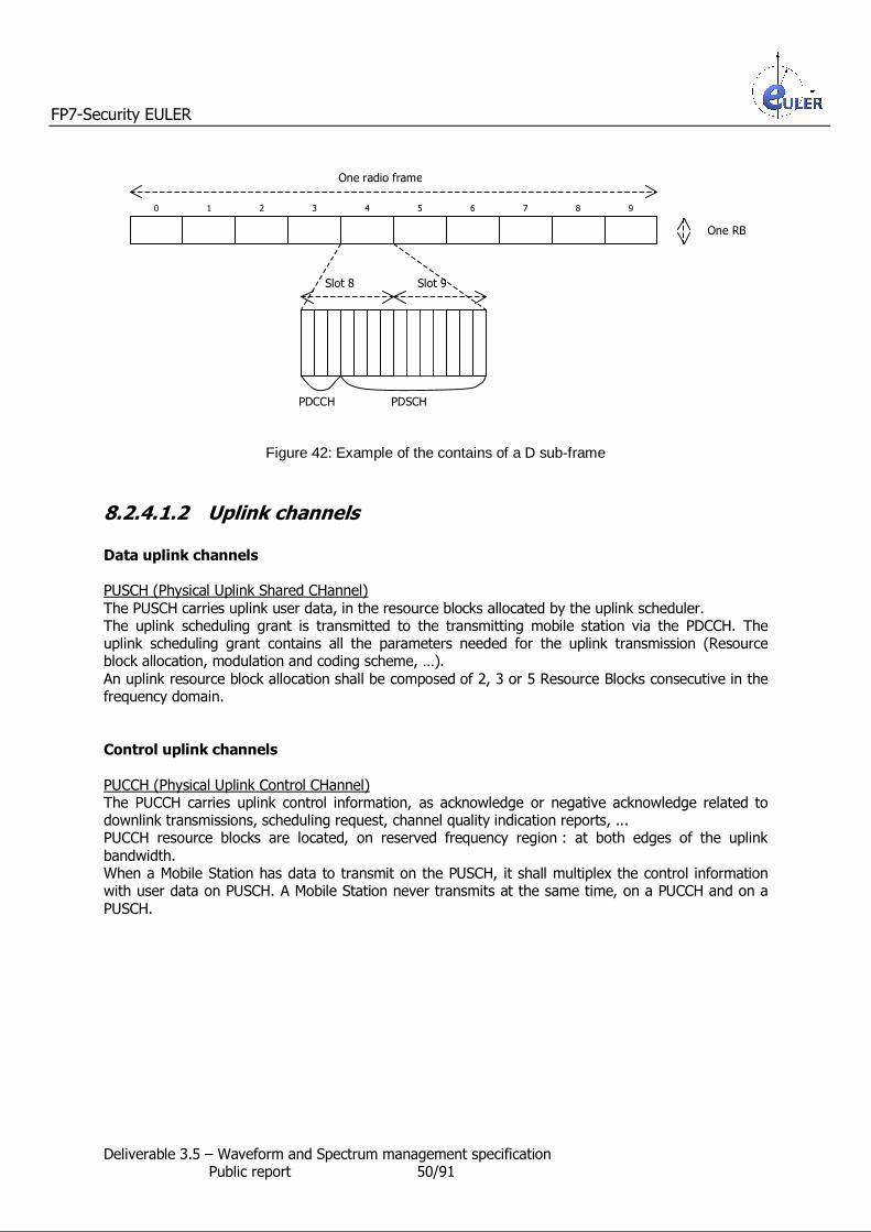
FP7-Security EULER
Deliverable 3.5 – Waveform and Spectrum management specification Public report 50/91
Figure 42: Example of the contains of a D sub-frame
8.2.4.1.2 Uplink channels
Data uplink channels PUSCH (Physical Uplink Shared CHannel)
The PUSCH carries uplink user data, in the resource blocks allocated by the uplink scheduler. The uplink scheduling grant is transmitted to the transmitting mobile station via the PDCCH. The uplink scheduling grant contains all the parameters needed for the uplink transmission (Resource block allocation, modulation and coding scheme, …).
An uplink resource block allocation shall be composed of 2, 3 or 5 Resource Blocks consecutive in the frequency domain.
Control uplink channels
PUCCH (Physical Uplink Control CHannel) The PUCCH carries uplink control information, as acknowledge or negative acknowledge related to downlink transmissions, scheduling request, channel quality indication reports, ... PUCCH resource blocks are located, on reserved frequency region : at both edges of the uplink
bandwidth. When a Mobile Station has data to transmit on the PUSCH, it shall multiplex the control information with user data on PUSCH. A Mobile Station never transmits at the same time, on a PUCCH and on a
PUSCH.
0 1 2 3 4 5 6 9 8 7
One radio frame
Slot 8 Slot 9
One RB
PDCCH PDSCH

FP7-Security EULER
Deliverable 3.5 – Waveform and Spectrum management specification Public report 51/91
Figure 43: Example of the contains of the uplink bandwidth in FDD
8.2.4.1.3 Air interface radio resource allocation In LTE, several kinds of radio resource allocation exist, they are all scheduled by the base station. Downlink resource allocation
According to applications requests in the base station, the downlink scheduler in the base station schedules the downlink resource allocation. The mobile station is warned of the downlink transmission which it is the destination by reading the PDCCH.
Uplink resource allocation The Scheduling Request (SR) is used for requesting uplink resources on the PUSCH for new transmission. According to the type of the allocated uplink resources, the mobile station shall transmit
a Scheduling Request on a specific channel (see Figure 44).
Uplink resource are available
for transmission in PUSCH
Uplink resource are available
for transmission in PUCCH
Scheduling request
transmission Channel
YES - PUSCH
NO YES PUCCH
NO NO PRACH
Figure 44: Choice of the scheduling request transmission Channel
Upon a SR reception, the uplink scheduler in the base station schedules the uplink resource allocation. The location in time and frequency of the allocated uplink resource blocks and all the parameters needed for the radio transmission as the modulation and coding scheme, are transmitted to the
mobile station via the PDCCH. Semi-persistent/Dynamic resource allocation
LTE standard enables persistent and dynamic resources allocation in uplink and downlink transmission :
• In dynamic allocation, an amount of resource blocks are allocated to a mobile station when
data have to be sent over the air. • In semi-persistent allocation, the same amount of resource blocks are periodically allocated to
a mobile station at regular interval. A semi-persistent allocation configuration is done via the
PDCCH. To distinguish in PDCCH a semi-persistent allocation from a dynamic allocation, a Semi Persistent Scheduling RNTI (SPS-RNTI) is associated to the semi-persistent allocation. A semi-persistent allocation can be reconfigured any time via the PDCCH. Between two
configurations, no information about the semi-persistent allocation is sent on the PDCCH. A
0
U bandwidth
PUCCH
PUCCH
PRACH PRACH
PRACH slot period
PUSCH
Time
Frequency
FP7-Security EULER
Deliverable 3.5 – Waveform and Spectrum management specification Public report 52/91
semi-persistent allocation can be stopped at any time. Semi-persistent uplink and downlink configurations are independent.
8.2.4.1.4 Other LTE functions The LTE standard provides other functions needed to develop an EULER LTE network as :
• Power Control. The Base Station controls the mobile station power transmission via the resource allocation mechanisms.
• Channel quality reporting. The Base Station may ask one or several to its registered mobile stations to do measurements.
• Scrambling. On the channels PDSCH, PUCCH and PUSCH, the scrambling code is generated
using the cell identifier and the RNTI related to the corresponding data transmission.
8.2.4.2 Compatibility with EULER system
As specified in an EULER network, a LTE Base Station controls the downlink and uplink radio resources allocations in multiples of one resource block among the users at each time. Moreover, the LTE uplink and downlink physical channels provide in both directions (PHICH or PUCCH or PUSCH) the HARQ mechanism, essential mechanism in an EULER network (see §6.2.2.3).
The PCFICH is present in each downlink sub-frame. It carries the size of the PDCCH. Because several EULER LTE base stations may write in one sub-frame : one in the PDCCH and one in the PDSCH. In an EULER LTE network, the PDCCH size must be part of the EULER LTE configuration and so must be
known by all the EULER LTE devices (base stations and mobile stations). So, the PDCCH shall be the same number of OFDM symbols (for example : three) in all the sub-frames. Then, the broadcast of the PCFICH is not anymore necessary.
To avoid a long search, the location of PDCCH depends on the RNTI associated to the transmission (Semi Persistent Scheduling RNTI and Cell RNTI). When a same RNTI is used by several EULER LTE
systems to access their mobile stations, then the associated channels could be used by several systems at the same time. More than 65400 values of RNTIs (Semi Persistent Scheduling RNTI and Cell RNTI) are available. One solution, to avoid multiple accesses to a channel, is to share the RNTIs between the EULER LTE systems at the EULER LTE network configuration.
The semi persistent resource allocation mechanism exactly matches to the EULER radio resource allocation described in §6.6.4.
8.2.5 Reference Signals
8.2.5.1 Description
Downlink Reference Signals For non-MBSFN transmissions with one or two antennas, one downlink reference signal enables the LTE Mobile Station to estimate the downlink channel :
• The cell-specific reference signals are used to measure downlink information as the channel quality estimation, MIMO and handoff measurements. A cell specific reference signal is transmitted in all downlink non-MBSFN sub-frames in a cell.
When the number of antennas is 1 or 2, the cell-specific reference signal is carried by four resource elements per resource block and per antenna port. In time domain, the radio element location is static on the first OFDM symbol and on the third symbol starting by the
slot end. In frequency domain, the radio element location depends on the cell identifier.

FP7-Security EULER
Deliverable 3.5 – Waveform and Spectrum management specification Public report 53/91
Figure 45: Cell-specific reference signals representation with one antenna
Uplink Reference Signals Two uplink reference signals enable the LTE Base Station to estimate the uplink channel :
• The DeModulation Reference Signals (DM RS) is used for the channel estimation for coherent
demodulation. It is present in every transmitted uplink resource block. On PUSCH, it is located on the fourth symbol starting by the slot end. On PUCCH, the DM RS location depends on the PUCCH format.
• The Sounding Reference Signals (SRS) provides uplink channel quality information for next uplink frequency scheduling. Under the Base Station control, a Mobile Station transmits,
periodically, a sounding reference signal in parts of the bandwidth (PUCCH and PUSCH). The SRS is always located in all the resource elements of the last OFDM symbol of the selected Resource Block. In LTE TDD the Sounding Reference Signal (SRS) can be transmitted in symbols of the slot S besides. The SRS transmission can be done only in the resource blocks
not allocated for uplink data transmission. A LTE system enables to switch off the SRS transmission.
8.2.5.2 Compatibility with EULER system
The transmission of the downlink cell specific reference signals does not pose problems in an EULER LTE network, because it applies on downlink sub-frames allocated to a EULER LTE system. Otherwise,
it enables a mobile station to differentiate EULER LTE systems. In the same way, the transmission of the deModulation reference signals is fully compatible with an
EULER LTE system, because it applies too on uplink sub-frames allocated to a EULER LTE system. On the other hand, the transmission of the sounding reference signals is totally impossible in an
EULER LTE network, because it applies on the uplink sub-frames shared by all the coexisting EULER LTE systems. The transmission of the sounding reference signals should request a supplementary synchronization between all the coexisting EULER LTE systems, to access the shared uplink sub-frames, which does not exist. Fortunately, the LTE standard provides for the switching off the
transmission of the sounding reference signals. The LTE mechanisms associated to the Reference Signals transmission can be applied to a EULER LTE
network without any LTE standard changes. A first approach, the transmission of the sounding reference signals shall be switched off.
Time
One sub frame
One slot (0.5 ms)
12 sub-carriers
Time
One sub frame
One slot (0.5 ms)
Frequency
Cell Id = 0, 6, 12, …, nx6 Cell Id = 3, 9, 15, …, 3+ nx6
FP7-Security EULER
Deliverable 3.5 – Waveform and Spectrum management specification Public report 54/91
8.2.6 Conclusion The LTE standard can be considered as suitable candidate for EULER network adaptation. Few changes in LTE are nevertheless necessary to make LTE as an applicable technology as a basis for
EULER waveform : • The transmission of the synchronization signals of one EULER LTE system should be in a
specific place of the frame according to its entry rank in the EULER LTE network, to permit
several EULER LTE systems to coexist, • The number of OFDM symbols in the PDCCH shall be set in an EULER network and known
from all the EULER LTE systems.
• The transmission of the sounding reference signals must be switched off.
9 Simulation of the spectrum sharing in an EULER network
From the LTE standard, we have simulated, thanks to MATLAB, the sharing of a common spectrum by several EULER systems, coexisting in a unique EULER network.
Neither the EULER systems synchronization, nor the Relay Station entry in the EULER network, nor a Mobile Station entry in an EULER system is part of the simulation. The simulation consists merely of the allocation of Radio Blocks in a pool of Radio blocks in good understanding by Relay Stations.
9.1 Simulation hypotheses
9.1.1 LTE frame configuration The simulated EULER network is a LTE-TDD network, in the uplink downlink configuration : 1 (the number of downlink and uplink resource blocks are equated). It is composed of four Relay Stations
which share a common spectrum band of 5 MHz, centralized to 700 MHz (frequency not used usually in LTE but frequently used in PMR). We have supposed that each Relay Station (system 1 to 4) transmits its synchronization in a D sub-
frame and so that the Relays Station cannot measure the D sub-frame carrying its synchronization. So, a Relay Station may only allocate, in time, up to 3 D sub-frames by radio frame. For example, if the Relay Station 1 transmits its synchronization on the sub-frame 0, it may only allocate downlink
Radio Blocks in the D sub-frames, position 4, 5 or 9 (see Figure 46). There is no restriction for a Relay Station to measure U sub-frames. So, a Relay Station may allocate, in time, up to 4 U sub-frames by radio frame.
The 5 MHz bandwidth spectrum to share contains in frequency 25 radio blocks. So, by taking off the 6 central radio blocks used to transmit the Relay Station synchronization, in frequency, the number of
radio blocks available to transmit data is equal to 19 (see Figure 47). So, in the 5 MHz bandwidth spectrum, each Relay Station may allocate :
• in downlink direction, up to 57 radio blocks over the 76 available DL radio blocks and
• in uplink direction, up to 76 radio blocks over the 76 available UL radio blocks.

FP7-Security EULER
Deliverable 3.5 – Waveform and Spectrum management specification Public report 55/91
Figure 46: Simulated EULER TDD LTE radio frame
1 2 3 4 5 6 7 8 9 10
1 D1,1 S U1,1 U2,1 D2,1 D3,1 S U3,1 U4,1 D4,1 2 D1,2 S U1,2 U2,2 D2,2 D3,2 S U3,2 U4,2 D4,2 3 D1,3 S U1,3 U2,3 D2,3 D3,3 S U3,3 U4,3 D4,3 4 D1,4 S U1,4 U2,4 D2,4 D3,4 S U3,4 U4,4 D4,4 5 D1,5 S U1,5 U2,5 D2,5 D3,5 S U3,5 U4,5 D4,5 6 D1,6 S U1,6 U2,6 D2,6 D3,6 S U3,6 U4,6 D4,6 7 D1,7 S U1,7 U2,7 D2,7 D3,7 S U3,7 U4,7 D4,7 8 D1,8 S U1,8 U2,8 D2,8 D3,8 S U3,8 U4,8 D4,8 9 D1,9 S U1,9 U2,9 D2,9 D3,9 S U3,9 U4,9 D4,9 10 11 12 13 14 15
Synchronization zone
16 D1,16 S U1,16 U2,16 D2,16 D3,16 S U3,16 U4,16 D4,16 17 D1,17 S U1,17 U2,17 D2,17 D3,17 S U3,17 U4,17 D4,17 18 D1,18 S U1,18 U2,18 D2,18 D3,18 S U3,18 U4,18 D4,18 19 D1,19 S U1,19 U2,19 D2,19 D3,19 S U3,19 U4,19 D4,19 20 D1,20 S U1,20 U2,20 D2,20 D3,20 S U3,20 U4,20 D4,20 21 D1,21 S U1,21 U2,21 D2,21 D3,21 S U3,21 U4,21 D4,21 22 D1,22 S U1,22 U2,22 D2,22 D3,22 S U3,22 U4,22 D4,22 23 D1,23 S U1,23 U2,23 D2,23 D3,23 S U3,23 U4,23 D4,23 24 D1,24 S U1,24 U2,24 D2,24 D3,24 S U3,24 U4,24 D4,24 25 D1,25 S U1,25 U2,25 D2,25 D3,25 S U3,25 U4,25 D4,25
Figure 47 : Radio blocks representation in the simulated radio frame
9.1.2 Link budget simulation The link budget simulation permits :
• a Relay Station to measure all the received powers per radio block, it can listen to, during
each sub-frame time, and so per Relay Station to constitute a set of received power maps which will be used to help the Relay Station to determine a radio block occupancy rate.
• to calculate, per radio block, when a radio block is used by several transmitting entities to
transmit information, the resulting interferences at each receiving entities.
D S U U D D S D U U
One radio frame
System 2, 3, 4
System 1, 2, 3,
4
System 1, 2, 3,
4
System 1, 3, 4
System 1, 2, 4
System 1, 2, 3
System 1, 2, 3,
4
System 1, 2, 3,
4
Six central Radio Blocks
System 2, 3, 4
System 1, 2, 3,
4
System 1, 2, 3,
4
System 1, 3, 4
System 1, 2, 4
System 1, 2, 3
System 1, 2, 3,
4
System 1, 2, 3,
4
5 MHz bandwidth
Resource blocks which can be used by systems for the data transport
Resource blocks reserved to system synchronization
one radio frame
5 MHz bandwidth

FP7-Security EULER
Deliverable 3.5 – Waveform and Spectrum management specification Public report 56/91
9.1.2.1 Link Budget basic definitions
The link budget is the accounting of all of the gains and losses from the transmitter, through the medium to the receiver.
A simple link budget equation looks like this :
Received Power (dBm) = Transmitted Power (dBm) + Gains (dB) - Losses (dB) Or might look like :
PRx = PTx + GTx - LTx - PLAvailable - ML + GRx – LRx Where
• PRx = received power (dBm)
• PTx = transmitter output power (dBm) • GTx = transmitter antenna gain (dBi)
• LTx = transmitter losses (coax, connectors, noise...) (dB) • PLAvailable = path loss(dB)
• ML = Margin losses (fast fading margin, shadowing margin, ...) (dB) • GRx = receiver antenna gain (dBi)
• LRx = receiver losses (coax, connectors, noise...) (dB)
The path loss (PLAvailable) calculation is detailed in section 9.1.2.3.
Margin losses :
• The shadowing margin ( inLogNormalML arg ) is simulated by a random number generated from
the normal distribution with mean parameter 0 and standard deviation parameter 8. A
different shadowing margin is associated to each triplet (receiver, transmitter, transmission
direction – UL or DL -). • No fast fading margin has been introduced in the MATLAB simulation.
The other parameters can be calculated from the equipments constant (see section 9.1.2.2). To the so calculated received power (PRx) shall be added, in Watt, to a thermal noise depending on
the receiver sensibility and the used channel bandwidth (see section 9.1.2.4).
9.1.2.2 Gains and losses due to equipments
Figure 48 presents gains and losses due to equipments.
Relay Station Mobile Station Maximum transmission power PTx, transmitter side
PRx, receiver side
37dBm (5 W)
30dBm (1 W)
Cable Loss LTxCable: transmitter side
LRxCable: receiver side
2 dB 2 dB
Antenna gain (omnidirectional configuration)
GTx, transmitter side GRx, receiver side
10 dbi 0 dBi
Noise figure
NFRx, receiver side
2 dB 7 dB
Height of antennas 5 m 1,5 m
Figure 48 : Link budget parameters

FP7-Security EULER
Deliverable 3.5 – Waveform and Spectrum management specification Public report 57/91
9.1.2.3 Path loss The path loss depends on the frequency carrier and the distance between the transmitter and the receiver.
The propagation models used here are the Hata and the Extended Hata Models in Sub-urban environment:
• Hata model is available for a distance smaller than 20km.
• For a distance greater than 20km, the extended Hata model is more precise. The distance between the transmitter and the receiver shall not exceed 20 km in our simulation
scenario. Hata Model:
)(log*)log*55,69,44(log*82,13log*10,2655,69 mhh hdhhfPL α−−+−+= ,
With :
• 4,5))²28/(log(*2)8,0log*56,1(*)7,0log*1,1()( ++−−−= ffhfh mmα
• f : central frequency (MHz) • hb : height of the Relay Station (m) • hm : height of the Mobile Station (m). • d : Distance between the Relay Station and the Mobile Station (km). • PL : Attenuation of the model. (dB)
9.1.2.4 Thermal Noise per Radio Block
The Thermal Noise depends on the used channel bandwidth. To one Radio Block, the Thermal Noise has been computed following the number of used sub-carriers :
)*log(*10174 SubcarrierspaceTh UsedSubN +−=
With :
• Subspace = Sub-carrier spacing : 15 kHz • Usedsub-carrier = Number of used sub-carriers in a Radio Block: 12.
So, according to the station noise figure, to each receiving station can be associated a Thermal Noise per Radio Block :
• -119.45 dBm, for a Relay Station, • -114.45 dBm, for a Mobile Station.
9.1.3 Transmit Power Control configuration The Transmit Power Control functionality permits to limit the transmitting power of the Relay Stations and the Mobile Stations, according to the geographical position of the transmitter and the receiver. The Transmit Power Control functionality has been implemented in our simulation software for the
Relay Stations and the Mobile Stations. The signal noise ratio expected by the Transmit Power Control functionality is equal to 5dB ± 1 dB.
Moreover, in a radio frame, a Relay Station may transmit information in several Radio Blocks, located on the same D sub-frame. The overall power transmitted by a Relay Station, during one D sub-frame time is limited to the maximum Relay Station transmitting power, defined Figure 48.
Finally, for the simulation, we restricted the Mobile Station transmission to one radio block per U sub-frame.

FP7-Security EULER
Deliverable 3.5 – Waveform and Spectrum management specification Public report 58/91
9.1.4 Power measurements Power measurements are only done by the Relay Stations.
Each Relay Station measures the power it receives for all the Radio Blocks it can and stores the measurements in a map. The measurement map is associated to a time. The number of measurement maps, that each Relay Station may store is, in our simulation software,
limited to 20.
9.1.5 Radio Block allocation According to the radio block measurements, a Relay Station allocates or not radio resource to an application.
A mean of its measurement maps is done by the Relay Station. To each Radio Block is so associated a mean received power.
The Radio Blocks are sorted by mean received power and per type U and D. When no measurement, at all, is available for a Radio Block in the Relay Station, the Radio Block cannot be allocated.
A Radio Block with a mean received power of - 40 dBm is supposed completely busy by the Relay Station and so cannot be allocated.
In the resting Radio Blocks, the Relay Station selects the N freest Radio Blocks available in a range of 10 dBm (N could be equal to 0).
When no Radio Block is available (N = 0), the Radio Block allocation is refused. U Radio Block allocation
The Relay Station randomly selects a U Radio Block amongst the N freest U Radio Blocks available. D Radio Block allocation As in U Radio Block allocation, the Relay Station randomly selects a D Radio Block amongst the freest
D Radio Blocks available. When several D Radio Blocks are requested at the same time, the Relay Station tries as much as possible to select all the D radio blocks on the same sub-frame.
When a Relay Station transmits, during a D sub-frame, it cannot measure at the same time. Therefore, rapidly, the 3 available D sub-frames for a Relay Station, would be unusable for a new allocation, because of the impossibility to measure them. So, in the simulation software, each time a
new D Radio Block is allocated on a sub-frame, the Relays Station tries to allocate the maximum D Radio Blocks on the selected D sub-frame, as long as the received power of the available D Radio Blocks is lower than - 40 dBm and so, to switch already allocated D Radio Blocks to the new selected D sub-frame.
9.1.6 Collisions and interferences When one radio block is used for data transmission by several Relay Stations, our simulation software shall calculate if the signals transmitted in the same Radio Blocks are interfering or not for each receiver point of view.
So, we calculate, thanks to the link budget equation, at each receiving station : • the received power of the expected signal and • the received power of the non expected signal, including the thermal noise of the receiving
station.

FP7-Security EULER
Deliverable 3.5 – Waveform and Spectrum management specification Public report 59/91
The ratio of the received powers for a radio block at a receiving station shall give the Signal to Noise
Ratio (SNR). • When the Signal to Noise Ratio is lower than 5 dB, we consider that the receiving station has
been interfered by the use of the radio block by other stations and so, that the collision is true in the Radio Block for that receiver2.
• Otherwise (the Signal to Noise Ratio is greater or equal to 5 dB), we consider that the
receiving station has not been interfered at all by the use of the radio block by other stations and so, that the collision is false in the Radio Block for that receiver2.
When, during a radio block allocation, true collisions appear several times (at least 5 times) on one
radio block, the simulation software processes the Radio Block change function.
9.1.7 Radio Block change function The Radio Block change function intervenes only when a receiving station cannot read a Radio Block in cause of too many interferences, for some time. It permits to schedule the radio block release and re-allocation.
The Radio Block change function starts by scheduling the release and re-allocation of the interfered radio block. A random number between 5 and 15 gives the number of radio frames to run before
starting the Radio Block change. Moreover, the number of true collisions associated to the Radio Block for that receiving station is reset to 0. 5 radio frames before starting the Radio Block change, the true collisions associated to the Radio
Block for that receiving station are once again counted. When the date of Radio Block change comes, if the number of the true collisions associated to the
Radio Block for that receiving station is greater or equal to 3, the Radio block allocation is released and a new Radio Block allocation is requested. Otherwise (the number of the true collisions associated to the Radio Block for that receiving station is lower than 3), no action is processed, the Radio Block
allocation is kept.
9.1.8 Simulated normalized traffic unit The chosen normalized traffic unit or throughput unit in a Relay Station is equal to two Radio Blocks in downlink and two Radio Blocks in uplink. The normalized traffic unit is generated in MATLAB via an application : an individual communication
between two Mobile Stations registered to the same Relay Station. During the simulation, first a Relay Station is randomly selected, then two Mobile Stations not already
involved in an individual communication are randomly selected. The application needs are two Radio Blocks in uplink direction (one per Mobile Station) and two Radio
Blocks in downlink direction (one per Mobile Station) in all the radio frame (see Figure 49). When, at least, one Radio Block allocation has been refused for an application, the application is immediately cancelled.
During the simulation, the number of applications per Mobile Station is limited to one. A simulated application lasts between 5 and 10 seconds (random time), so between 500 and 1 000
radio frames.
2 One Station may receive a interefered signal on a Radio Block, as on the same Radio Block, another Station may receive a not interefered signal.

FP7-Security EULER
Deliverable 3.5 – Waveform and Spectrum management specification Public report 60/91
Mobile Station (MS)
Relay Station (RS)
Radio connection
Legend
1 RB D
1 RB U 1 RB D
1 RB U
Figure 49 : Simulated individual communication
9.1.9 Geographical repartition of the Stations The 4 Relay Stations are equitably dispatch on a field. The field is a square of side equal to 2x, with x value varying from 200 m to 4 km (step 200 m). So, our simulation field is a square, which size varies
from 400 m to 8 km with a step of 400 m. A representation of the field is shown Figure 50.
300 Mobile Stations are randomly spread out over the entire field. Each Mobile Station registers to its nearest Relay Station.
Mobile Station (MS)
Relay Station (RS)
Radio connection
Legend
RS1
RS3 RS4
RS3
x x
x
x
x
x
Figure 50: Simulation : the Relay Stations positions

FP7-Security EULER
Deliverable 3.5 – Waveform and Spectrum management specification Public report 61/91
9.1.10 Simulation scenario First the Relay Stations are initiated, then the Mobile Stations.
When the Stations are ready, the simulation software processes the following actions, at each 10 ms (radio frame time) :
• Each Relay Station does its measurements (cf section 9.1.4) and so acquires a new
measurements map. • A new application is requested (cf section 9.1.8). • Each Relay Station and Mobile Station involved in an application transmits its signal on the
allocated Radio Blocks with the appropriate power (cf section 9.1.3). • Radio Block collisions are detected and Radio Block interferences are calculated (cf section
9.1.6). Eventually, Radio block changes are processed (cf section 9.1.7). At each radio frame, the MATLAB scenario measures per Relay Station :
• the number of Radio Blocks allocated by the Relay Station, • the number of collided Radio Blocks (collisions),
• the number of false collisions (not interfering collisions), • the number of true collisions (interfering collisions),
• the number of Radio Block changes, • the number of running applications.
Moreover, the MATLAB scenario counts, per application, the number of interferences (true collisions). From thanks to these numbers we can deduce, at each radio frame, the following numbers :
• The sum for the 4 Relay Stations of the numbers of Radio Blocks allocated by each Relay
Station gives the global number of the allocated Radio Blocks in the network. A Radio Block may be allocated at the same time by 1, 2, 3 or the 4 Relay stations.
• The sum for the 4 Relay Stations of the numbers of collided Radio Blocks allocated by each
Relay Station gives the global number of the collisions in the network. A collision may involve 2, 3 or the 4 Relay stations.
• The sum for the 4 Relay Stations of the numbers of false collisions in each Relay Station gives the global number of the false collisions in the network.
• The sum for the 4 Relay Stations of the numbers of true collisions in each Relay Station gives
the global number of the true collisions in the network. • The sum for the 4 Relay Stations of the Radio Block changes in each Relay Station gives the
global number of the Radio Block changes in the network. • The sum for the 4 Relay Stations of the running applications in each Relay Station gives the
global number of the running applications in the network and so the number of the individual
communications processed at the same time in the network. • Some of the applications may be disturbed : a true collision is detected on one of the Radio
Blocks transmitting information for that application. We count in the system the number of applications :
o which has not been interfered at all, o which at least 1 Radio Block has been interfered,
o which at least 5 Radio Blocks have been interfered, o which at least 20 Radio Blocks have been interfered.
No direction distinction is done on Radio Block.
The scenario lasts 9 000 radio frames, so 1 mn 30 s in real time. To avoid the beginning artifacts, the results shall be recorded on the 6 000 last radio frames (1 mn). Instant representation presented in
the following figures shows the last 1 000 last radio frames results. With a x value varying from 200 m to 4 km, each scenario has been was run 10 times.

FP7-Security EULER
Deliverable 3.5 – Waveform and Spectrum management specification Public report 62/91
9.2 Simulation results
9.2.1 The 4 Relay Stations activated During the simulation the 4 Relays Stations are activated.
9.2.1.1 Stations repartition in the field The 4 Relay Stations are equally spreads out in the field.
300 Mobile Stations are randomly spreads out in the field around the Relay Stations. Each Mobile Station registers to its nearest Relay Station.
Examples of the stations repartition, when the field is a square of 4 km x 4 km ( x = 2 km) are given in Figure 51. Relay Stations positions are set to :
• RS 1 (1 km, 1 km) or (x/2, x/2), • RS 2 (1 km, 3 km) or (x/2, 3x/2),
• RS 3 (3 km, 3 km) or (3x/2, 3x/2), • RS 4 (3 km, 1 km) or (3x/2, x/2).
Mobile Stations positions are all different.

FP7-Security EULER
Deliverable 3.5 – Waveform and Spectrum management specification Public report 63/91
X in km
Y in km
0
0.5
1
1.5
2
2.5
3
3.5
4
0 0.5 1 1.5 2 2.5 3 3.5 4
0 0.5 1 1.5 2 2.5 3 3.5 4
Legend:
+ : RS 1 : MS registered to the RS 1 + : RS 2 : MS registered to the RS 2 + : RS 3 : MS registered to the RS 3 + : RS 4 : MS registered to the RS 4
0
0.5
1
1.5
2
2.5
3
3.5
4
X in km 0 0.5 1 1.5 2 2.5 3 3.5 4 0 0.5 1 1.5 2 2.5 3 3.5 4
Y in km
Figure 51: Stations repartition examples, x = 2km
9.2.1.2 Radio block allocation Our simulated LTE radio frame, in the uplink downlink configuration 1 on 5 MHz bandwidth spectrum,
is made of 76 D Radio Blocks (used for downlink data transmission), 76 U radio Blocks (used for uplink data transmission) and 38 S Radio Blocks (not used for data transmission), because the 6 central Radio Blocks are only used for synchronization.
So per radio frame, the number of Radio Blocks useable for transmission is equal to 152. When we add all the Radio Blocks allocated by each Relay Station, we obtain the number of Radio Blocks allocated in the network.

FP7-Security EULER
Deliverable 3.5 – Waveform and Spectrum management specification Public report 64/91
By dividing this number by the number of Radio Blocks useable for transmission in a radio frame, we obtain the percentage of the Radio Blocks allocated in the network.
The following figures show during 1 000 radio frames, the evolution of :
• the percentage of the Radio Blocks allocated in the network,
• the percentage of the Radio Blocks allocated by, at least, 2 Relay Stations (Collisions) and • the percentage of Radio changes,
according to the dimension of the field. We can notice that :
• the closest are the Relay Stations, the most Radio Blocks are allocated. So in a field of 400 m2 (Figure 52), each Radio Block is allocated by about one Relay Station and half (160% of the available Radio Blocks are allocated). The percentage of the Radio Blocks allocated in the
network decreases as much the distance between the Relay Stations increases : at x = 2 km, the percentage of the Radio Blocks allocated in the network is around 100 % (Figure 54), at x = 8 km, it reaches 70 % (Figure 55).
• The percentage of the collisions curves follows the curves of percentage of the Radio Blocks allocated. The closest are the Relay Stations, the most important are the number of collisions. Collisions are detailed in §9.2.1.3.
• The percentage of Radio Block changes is negligible compare to the percentage of the Radio Blocks allocated in the network (see details in §9.2.1.3).

FP7-Security EULER
Deliverable 3.5 – Waveform and Spectrum management specification Public report 65/91
0 100 200 300 400 500 600 700 800 900 10000
20
40
60
80
100
120
140
160
180P
erce
ntag
e (/
Nb
usea
ble
DU
s)
Time in frame
Nb of RB Allocated (D, U) by BS1, BS2, BS3 and BS4
Nb of RB with CollisionsNb of RB change in BS1, BS2, BS3 and BS4 because of collisions
Figure 52: Radio Block allocation, x = 200 m
0 100 200 300 400 500 600 700 800 900 10000
20
40
60
80
100
120
140
160
Per
cent
age
(/ N
b us
eabl
e D
Us)
Time in frame
Nb of RB Allocated (D, U) by BS1, BS2, BS3 and BS4
Nb of RB with CollisionsNb of RB change in BS1, BS2, BS3 and BS4 because of collisions
Figure 53: Radio Block allocation, x = 1 km
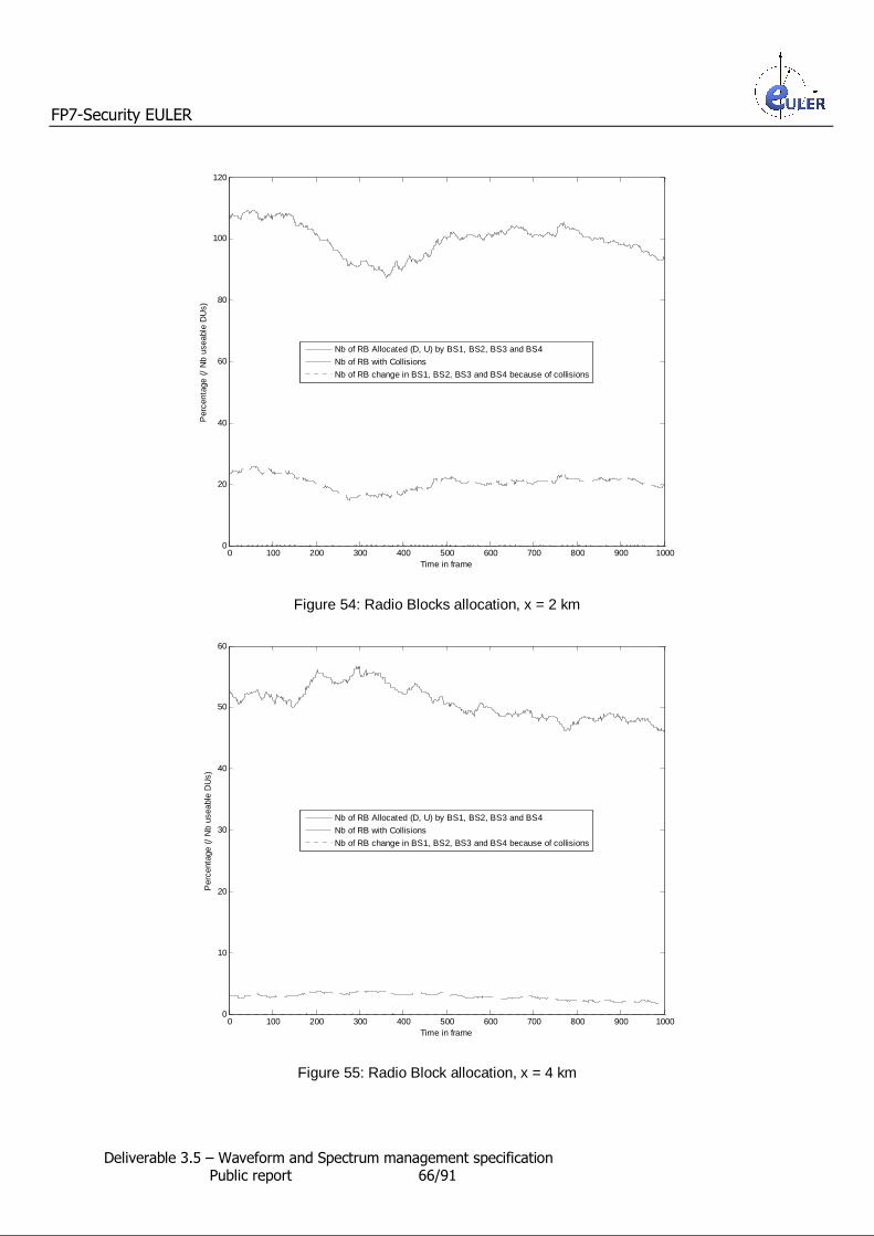
FP7-Security EULER
Deliverable 3.5 – Waveform and Spectrum management specification Public report 66/91
0 100 200 300 400 500 600 700 800 900 10000
20
40
60
80
100
120
Per
cent
age
(/ N
b us
eabl
e D
Us)
Time in frame
Nb of RB Allocated (D, U) by BS1, BS2, BS3 and BS4
Nb of RB with Collisions
Nb of RB change in BS1, BS2, BS3 and BS4 because of collisions
Figure 54: Radio Blocks allocation, x = 2 km
0 100 200 300 400 500 600 700 800 900 10000
10
20
30
40
50
60
Per
cent
age
(/ N
b us
eabl
e D
Us)
Time in frame
Nb of RB Allocated (D, U) by BS1, BS2, BS3 and BS4
Nb of RB with Collisions
Nb of RB change in BS1, BS2, BS3 and BS4 because of collisions
Figure 55: Radio Block allocation, x = 4 km

FP7-Security EULER
Deliverable 3.5 – Waveform and Spectrum management specification Public report 67/91
9.2.1.3 True/false Collision repartition
A collision is a Radio Block allocated by at least 2 Relay Stations in the same radio frame. Collisions may be false (not interfering for the receiving station) or true (interfering for the receiving station).
The collisions curves have been obtained by adding all the collisions in all the Relay Stations and dividing the number by the number of Radio Blocks useable for transmission in a radio frame.
The following figures show during 1 000 radio frames, the evolution of : • the percentage of the collisions in the network,
• the percentage of the false collisions in the network, • the percentage of the true collisions in the network and
• the percentage of Radio changes in the network, according to the dimension of the field.
We can notice that : • Most of the collisions are false. The percentage of the true collisions in the network is smaller
than 2,3 % of the useable Radio Blocks, whatever the field dimension. The number of true
collisions decreases with the field size (0,14 % of the useable Radio Blocks when x = 4 km). If we compare the number of true collisions with the number of collisions : the number of true collisions matches to a range between 2,1 % and 5,3 % of the collisions.
• The number of Radio changes is small compare to the number of the true collisions : the number of Radio Block changes match to a value between 0,4 % and 0,65 % of the number of true collisions).
0 100 200 300 400 500 600 700 800 900 10000
50
100
150
Per
cent
age
(/ N
b us
eabl
e D
Us)
Time in frame
Nb of Collisions in BS1, BS2, BS3 and BS4
Nb of False Collisions in BS1, BS2, BS3 and BS4Nb of True Collisions in BS1, BS2, BS3 and BS4
Nb of RB change in BS1, BS2, BS3 and BS4 because of collisions
Figure 56: True/false collisions repartition, x = 200 m
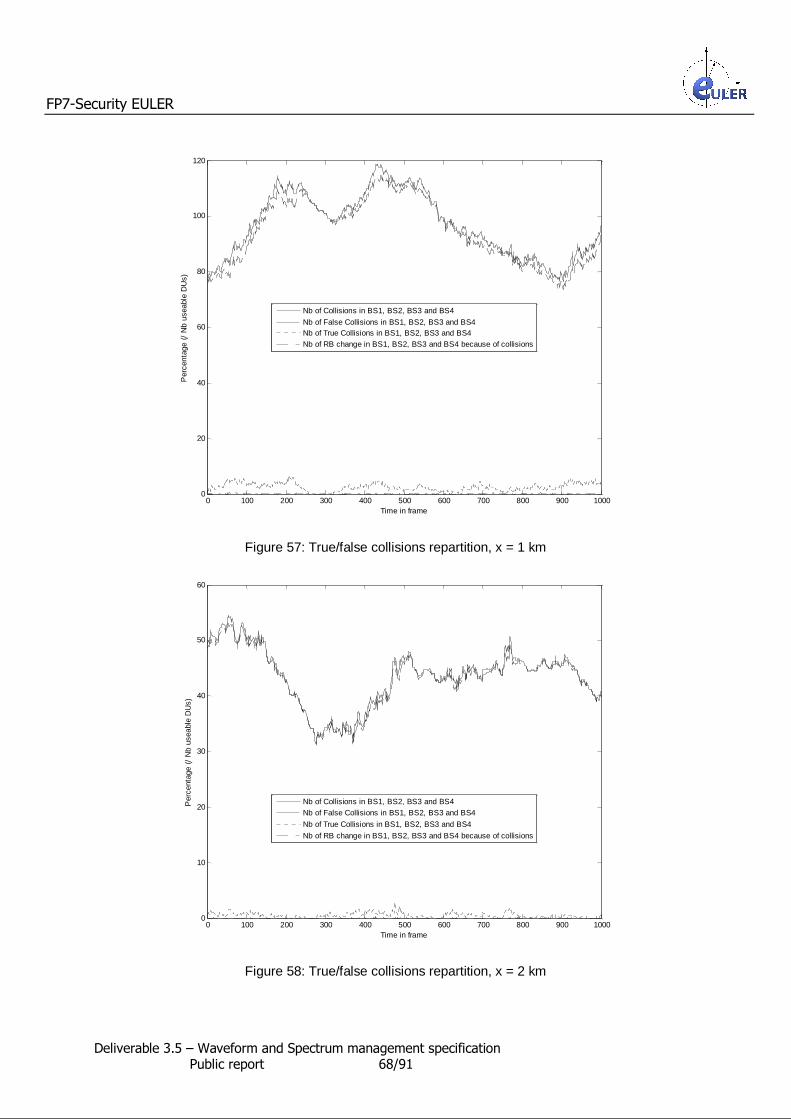
FP7-Security EULER
Deliverable 3.5 – Waveform and Spectrum management specification Public report 68/91
0 100 200 300 400 500 600 700 800 900 10000
20
40
60
80
100
120
Per
cent
age
(/ N
b us
eabl
e D
Us)
Time in frame
Nb of Collisions in BS1, BS2, BS3 and BS4
Nb of False Collisions in BS1, BS2, BS3 and BS4Nb of True Collisions in BS1, BS2, BS3 and BS4Nb of RB change in BS1, BS2, BS3 and BS4 because of collisions
Figure 57: True/false collisions repartition, x = 1 km
0 100 200 300 400 500 600 700 800 900 10000
10
20
30
40
50
60
Per
cent
age
(/ N
b us
eabl
e D
Us)
Time in frame
Nb of Collisions in BS1, BS2, BS3 and BS4Nb of False Collisions in BS1, BS2, BS3 and BS4
Nb of True Collisions in BS1, BS2, BS3 and BS4
Nb of RB change in BS1, BS2, BS3 and BS4 because of collisions
Figure 58: True/false collisions repartition, x = 2 km

FP7-Security EULER
Deliverable 3.5 – Waveform and Spectrum management specification Public report 69/91
0 100 200 300 400 500 600 700 800 900 10000
1
2
3
4
5
6
7
8
9
Per
cent
age
(/ N
b us
eabl
e D
Us)
Time in frame
Nb of Collisions in BS1, BS2, BS3 and BS4Nb of False Collisions in BS1, BS2, BS3 and BS4
Nb of True Collisions in BS1, BS2, BS3 and BS4
Nb of RB change in BS1, BS2, BS3 and BS4 because of collisions
Figure 59: True/false collisions repartition, x = 4 km
9.2.1.4 Normalized traffic unit repartition
The normalized traffic unit is represented by an individual communication involving two Mobile Stations registered to the same Relay Station. The following figures show during 1 000 radio frames, the evolution of :
• the global number of applications in the network, • the global number of interfered applications (at least one Radio Blocks has been interfered) in
the network, • the number of applications in which at least five Radio Blocks has been interfered in the
network,
• the number of applications in which at least twenty Radio Blocks has been interfered in the network.
according to the dimension of the field. We can notice that :
• The smallest is the field size, the most applications runs in the networks : from around 60
applications (x = 200 m) to around 19 applications (x = 4 km). • From x = 400 m to x = 2 km, a lot of applications are interfered (between 80 % and 90 % of
the applications). But after the interfered applications go down to 50 %.

FP7-Security EULER
Deliverable 3.5 – Waveform and Spectrum management specification Public report 70/91
0 100 200 300 400 500 600 700 800 900 10000
10
20
30
40
50
60
70
Nb
of A
pplic
atio
ns
Time in frame
Individual Call MonoRBInterfered individual Call MonoRBIndividual Call MonoRB with at least 5 interferences
Individual Call MonoRB with at least 20 interferences
Figure 60: Applications repartition, x = 200 m
0 100 200 300 400 500 600 700 800 900 10000
10
20
30
40
50
60
Nb
of A
pplic
atio
ns
Time in frame
Individual Call MonoRB
Interfered individual Call MonoRBIndividual Call MonoRB with at least 5 interferencesIndividual Call MonoRB with at least 20 interferences
Figure 61: Applications repartition, x = 1 km

FP7-Security EULER
Deliverable 3.5 – Waveform and Spectrum management specification Public report 71/91
0 100 200 300 400 500 600 700 800 900 10000
5
10
15
20
25
30
35
40
45
Nb
of A
pplic
atio
ns
Time in frame
Individual Call MonoRBInterfered individual Call MonoRB
Individual Call MonoRB with at least 5 interferencesIndividual Call MonoRB with at least 20 interferences
Figure 62: Applications repartition, x = 2 km
0 100 200 300 400 500 600 700 800 900 10000
5
10
15
20
25
Nb
of A
pplic
atio
ns
Time in frame
Individual Call MonoRB
Interfered individual Call MonoRBIndividual Call MonoRB with at least 5 interferences
Individual Call MonoRB with at least 20 interferences
Figure 63: Applications repartition, x = 4 km

FP7-Security EULER
Deliverable 3.5 – Waveform and Spectrum management specification Public report 72/91
9.2.1.5 Results synthesis
With a x equal from 200 m to 4 km, we have synthesized the results obtained by simulation.
Figure 64 shows according to x, the percentage of mean number of Radio Blocks which have been allocated in the network and the percentage of mean collided radio Blocks, compared to the number of useable Radio Blocks. The standard deviation of the allocated Radio Blocks varies between 3 % (x = 3,6 km) and 10 %
(x = 2 km).
Percentage of Radio Blocks allocated in the network per radio frame
020406080
100120140160180
0,2 0,4 0,6 0,8 1 1,2 1,4 1,6 1,8 2 2,2 2,4 2,6 2,8 3 3,2 3,4 3,6 3,8 4
x in km
% (/
D+
U u
seab
le R
Bs)
Radio BlocksD+URB withcollisions
Figure 64: Radio Block allocation
We can notice that : • much more Radio Blocks are allocated when the distance between the Relay Stations is small
or, says in an other way, when the Mobile Stations are close to the Relay Station to which they are registered. Even, when the distance between the Relay Stations becomes important, not all the useable Radio Blocks are allocated. The change appears with a x around 2 km. This can be explained thanks to the transmit power control mechanism : when the distance
between the Relay Stations is small, the distance between the Relay Station and the Mobile Stations involved in the applications is small too, so thanks to the transmit power control mechanism, the transmitting powers in uplink and downlink directions are low. In particular,
in downlink direction, the sum of the powers transmitted in a D sub-frame does not reach the maximum power a Relay Station may transmit. In the opposite, when the field covered by a Relay Station is large, some Mobile Stations are far from the Relay Station. So, the Relay Station must transmit information to them with a high power. Thus, the Relay Station is
limited in its transmission during the same D sub-frame of several D radio Blocks by its maximum transmitting power.
• the number of collisions is greater when the field size is small (from 35 % of the allocated
Radio Blocks when x = 200 m to 6 % of the allocated Radio Blocks when x = 4 km). Because of the power limitation when the field is large, less Radio Blocks are requested and so the best Radio Blocks, according to the measurements, are chosen (no D sub-frame filling).

FP7-Security EULER
Deliverable 3.5 – Waveform and Spectrum management specification Public report 73/91
Figure 65 shows according to x, the collisions splitting between the true and the false collisions.
Collision repartition in the network per radio frame
0
20
40
60
80
100
120
1 2 3 4 5 6 7 8 9 10 11 12 13 14 15 16 17 18 19 20
x in km
% (
/ col
lisio
ns)
False collisions
True collisions
Figure 65: Collisions repartition in the network per radio frame
We can notice that : • Most of the collisions are false whatever the field size (between 97,5% and 99% of the
collisions), so the number of the true collisions is very few. Figure 67 shows according to x, the percentage of the collisions and the Radio Block changes
compared to the allocated Radio Blocks.
Collisions and Radio Block changes in the network per radio frame
00,20,40,60,8
11,21,41,61,8
0,2 0,61
1,4 1,8 2,2 2,63
3,4 3,8
x in km
% (/
Allo
cate
d R
adio
Blo
cks)
True collisionRadio Block change
Figure 66: Collisions and Radio Block changes in the network per radio frame
We can notice that : • Even, if the amount of true collisions is a little bit higher when the distance between the Relay
Stations is around 1 km, it is not high compare to the number of the allocated Radio Blocks (less than 1,7 %).
• The number of Radio Block Changes per radio frame is quite few (less than 0,1 % of the
allocated Radio Blocks).

FP7-Security EULER
Deliverable 3.5 – Waveform and Spectrum management specification Public report 74/91
Figure 67 shows according to x, the Radio Block change repartition according to the true collisions.
Radio Block changes repartition in the network per radio frame
0
1
2
3
4
5
6
7
0,2 0,4 0,6 0,8 1 1,2 1,4 1,6 1,8 2 2,2 2,4 2,6 2,8 3 3,2 3,4 3,6 3,8 4
x in km
% (/
Tru
e co
llisi
on
s)
RB Change
Figure 67: Radio block changes repartition in the network per radio frame
We can notice that :
• Whatever the field size, the number of the Radio Block change is included between 4 % and 6,4 % of the number of the true collisions. As seen in the figure below; it is quite few.
Figure 68 shows according to x, the mean number of running applications in the network. The repartition of the running applications are seen Figure 69.
Number of running applications
0
10
20
30
40
50
60
70
0,2
0,6 1 1,
41,
82,
22,
6 3 3,4
3,8
x in km
Applications
Applications with at least 1Radio Block disturbed
Applications with at least 5 Radio Blocks disturbed
Applications with at least20 Radio Blocks disturbed
Figure 68: Number of running applications
We can notice that : • The number of the running applications decreases as the distance between the Relay Stations
increase.
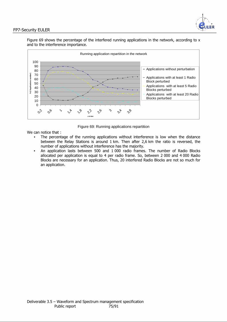
FP7-Security EULER
Deliverable 3.5 – Waveform and Spectrum management specification Public report 75/91
Figure 69 shows the percentage of the interfered running applications in the network, according to x and to the interference importance.
Running application repartition in the network
0102030405060708090
100
0,2 0,6 1 1,4 1,8 2,2 2,6 3 3,4 3,8
x in km
% (/
Ap
plic
atio
ns n
um
ber)
Applications without perturbation
Applications with at least 1 RadioBlock perturbedApplications with at least 5 RadioBlocks perturbedApplications with at least 20 RadioBlocks perturbed
Figure 69: Running applications repartition
We can notice that : • The percentage of the running applications without interference is low when the distance
between the Relay Stations is around 1 km. Then after 2,6 km the ratio is reversed, the number of applications without interference has the majority.
• An application lasts between 500 and 1 000 radio frames. The number of Radio Blocks
allocated per application is equal to 4 per radio frame. So, between 2 000 and 4 000 Radio Blocks are necessary for an application. Thus, 20 interfered Radio Blocks are not so much for an application.

FP7-Security EULER
Deliverable 3.5 – Waveform and Spectrum management specification Public report 76/91
9.2.2 Comparison with a network with only one active Relay Station In our simulation software, we des-activate all the Relay Stations and their Mobile Stations except one : the RS 4. So, the network is composed of the RS 4 and the 75 Mobile Stations registered to it.
The simulation software is run 10 times for each x value, with x varying from 200 m to 4 km.
9.2.2.1 Stations repartition in the field
The position of the Relay Station is fixed in the field (3*x/2, x/2).
75 Mobile Stations are randomly spreads out in a quarter of the field around the Relay Station 4. Each Mobile Station registers to RS 4. One example of the stations repartition, when the field is a square of 4 km x 4 km is given in Figure
70.
Y in km
Legend:
+ : RS 1 : MS registered to the RS 1 + : RS 2 : MS registered to the RS 2 + : RS 3 : MS registered to the RS 3 + : RS 4 : MS registered to the RS 4
X in km 0 1 2 3 4
0
0.
1
1.
2
2.
3
3.
Figure 70: Stations repartition examples, x = 2km

FP7-Security EULER
Deliverable 3.5 – Waveform and Spectrum management specification Public report 77/91
9.2.2.2 Radio blocks allocation
Figure 71 shows during 1 000 radio frames, the evolution of the percentage of the Radio Blocks allocated in the network, according to the dimension of the field.
We can notice that :
• Like when all Relay Stations are active, the number of allocated Radio Blocks is more
important when the Mobile Stations are close to the Relay Station.
0 100 200 300 400 500 600 700 800 900 10000
2
4
6
8
10
12
14
Time in frame
Nb
of A
pplic
atio
ns
x = 200 m
x = 1 km
x = 2 kmx = 4 km
Figure 71: Radio Blocks allocation in the unique RS 4

FP7-Security EULER
Deliverable 3.5 – Waveform and Spectrum management specification Public report 78/91
9.2.2.3 Results synthesis
With a x equal from 200 m to 4 km, we have synthesized the results obtained by simulation.
Figure 72 shows according to x, the percentage of mean number of Radio Blocks which have been allocated in the network compared to the number of useable Radio Blocks. The standard deviation of the allocated Radio Blocks varies between 1,8 % (x = 4 km) and 5,5 % (x = 2 km).
Percentage of Radio Blocks allocated in the network per radio frame (one Relay Station active)
0
10
20
30
40
50
60
0,2
0,6 1 1,
41,
82,
22,
6 3 3,4
3,8
x in km
% (
/ D+
U u
seab
le R
Bs)
Radio BlocksD+U
Figure 72: Radio Blocks allocation
We can notice that : • As previously, like when all Relay Stations are active, the number of allocated Radio Blocks is
more important when the Mobile Stations are close to the Relay Station.
• Because of the synchronization, the Relay Station cannot measure the totality of the D sub-frames (one D sub-frame is not measurable) and so it can only allocate Radio Blocks on three D sub-frames over the four. Moreover, because the simulated application requests the same
number of Radio Blocks in both directions, one fourth of the spectrum bandwidth could not be used by the Relay Station.

FP7-Security EULER
Deliverable 3.5 – Waveform and Spectrum management specification Public report 79/91
9.2.3 Comparison of the results : 4 Relay Stations active / 1 Relay Station active
By dividing the number of Radio Blocks allocated by the simulated EULER network with 4 active Relay
Stations by and the number of Radio Blocks allocated by the simulated EULER network with one active Relay Station, according to x, we obtain the use ratio of a Radio Block (Figure 73).
Figure 73: Use ratio of a Radio Block
We can notice that : • The diagram is mainly composed of three ranges,
o When the field size is quite small (x < 1,8 km), the use ratio of the allocated Radio Blocks is around 3.
o When the field size is large (x > 2,6 km), the use ratio of the allocated Radio Blocks is
near 4. o Otherwise, the ratio of the allocated Radio Blocks is around 3,5.
• The use ratio of a Radio Block is high and when the field size is high, close to its maximum.
Use ratio of a Radio Block
00,5
11,5
22,5
33,5
44,5
0,2 0,4 0,6 0,8 1 1,2 1,4 1,6 1,8 2 2,2 2,4 2,6 2,8 3 3,2 3,4 3,6 3,8 4
x in km
Ratio 4 RS active versus 1 RS active

FP7-Security EULER
Deliverable 3.5 – Waveform and Spectrum management specification Public report 80/91
10 Security analysis
10.1 Security issues of the dynamic spectrum management
The Dynamic Spectrum Management (DSM) method is used in Software Defined Radio and Cognitive Radio in order to mitigate the spectrum shortage problem. This flexible solution consists of a set of
techniques which is based on network information theory and game theory. Furthermore, the idea of DSM is also proposes principles from the fields of cross layer optimization, artificial intelligence etc. The idea of cognitive radio was proposed by Joseph Mitola in 1998 and it was a novel approach in
wireless communications. In [7] the term of cognitive radio was defined: “The term cognitive radio identifies the point at which wireless personal digital assistants (PDAs) and the related networks are sufficiently computationally intelligent about radio resources and related computer-to-computer communications to:
(a) detect user communications needs as a function of use context, and (b) to provide radio resources and wireless services most appropriate to those needs.”
• The idea of Cognitive Radio is different from the Software Defined Radio because this is a fully reconfigurable wireless black-box that automatically changes its communication variables in response to network and user demands. Nowadays, this concept comes in useful for the
efficient spectrum utilization, since most of the radio frequency spectrum is inefficiently utilized. For example cellular network bands are overloaded in most parts of the world, however, amateur radio frequencies are not. Observations are confirmed that spectrum
utilization depends on time and place. Furthermore, fixed spectrum allocation encumbers the unlicensed users in that the licensed frequency bands could be used, even when their transmissions would not interfere at all with the assigned service. That is why the utilization of licensed frequency bands by unlicensed users is allowed whenever it would not cause any
interference. DSM is a very important part of CR, which provides the ability to use or share the spectrum in an opportunistic manner. For the realization of DSM in CR systems, CR has to provide the following functions (Figure PUCCH format.
): • Spectrum sensing: detecting spectrum holes and sharing the spectrum without interfering
with other users.
• Spectrum management: selecting the best available channels for communication. • Spectrum mobility: maintaining seamless communication during the transition to better
spectrum. • Spectrum sharing: coexisting with other users in one channel.

FP7-Security EULER
Deliverable 3.5 – Waveform and Spectrum management specification Public report 81/91
Dynamic Spectrum
Management (DSM)
Spectrum management
Spectrum Mobility
Spectrum sensing
Spectrum sharing
Figure 74: Main functions of the DSM
The major principles of DSM are the followings:
• link adaptation
• bandwidth management • Multi-user MIMO
• pre-cancellation of estimated interference • combining unused channels (not pre-allocated) for a single user or bonding
In [8] the authors described the architecture of CR and proposed a classification about the existing solutions for CR networks or spectrum sharing. Figure EULER PMR Mobile Broadband network shows
three different kinds of classifications about CR networks.
CR Network
Network
architecture
Access
behaviour
Access
technology
Centralized
Cooperation
Non-Cooperation
Distributed
Underlay
Overlay
Figure 75: Classifications of CR network architecture
In the first classification of CR, the network architecture is examined. There are two different types:
one is a centralized network architecture and the other is a distributed network architecture. In case of the centralized network architecture the centralized network element (for example a base station) controls the allocation of the spectrum resources and the access procedures, or collects the spectrum
sensing information, meanwhile each sub-centralized entity transmits its measurement and other information to the central node. In the other type of network architecture, in the distributed solution each network element is responsible for the spectrum allocation and access based on decision

FP7-Security EULER
Deliverable 3.5 – Waveform and Spectrum management specification Public report 82/91
algorithms and voting mechanisms. It can be said that the centralized network architecture is more efficient, however, from the point of view of security and reliability the central node is a single point of
failure. The second classification bases on the access behavior. There are two common approaches: a cooperation and a non-cooperation solution. In case of cooperation way, the cognitive functions are
based on the coordination of the CR nodes, which exchange information in order to optimize the spectrum utilization. All the centralized network solutions are also cooperative solutions, however, there are distributed cooperative solutions, too. In contrast with the cooperative way, in a non-cooperative approach, each CR node implements its own cognitive function and there is no
information exchange between them. The cooperative solution is more reliable and more efficient than the non-cooperative one, however, in order to exchange information a common channel is needed. The third classification is the access technology. The two types of spectrum sharing are the spectrum
overlay and the spectrum underlay approach [9]. In case of overlay spectrum approach, a CR node is able to access that spectrum which has not been used by licensed users. That is why the interference to primary users is minimized. In other case, when a CR node uses underlay spectrum approach, CR
node operates below the noise level of primary users, consequently its transmit power is considered as noise by the primary user. The various CR network architectures has different level of security.
10.1.1 Security considerations In order to measure a system or application from the point of view of security a security measure is
needed. The National Security Agency (NSA) defines Information Assurance IA [10] as a set of “Measures that protect and defend information and information systems by ensuring their availability, integrity, authentication, confidentiality, and non-repudiation. These measures include providing for
restoration of information systems by incorporating protection, detection, and reaction capabilities.” Information assurance (IA) is the practice of managing risks related to the use, processing, storage, and transmission of information or data and the systems and processes used for those purposes. The
full range of IA comprises not only the digital data, but analog or physical form, too. Information assurance as a field has grown from the practice of information security which in turn grew out of practices and procedures of computer security. Three different models were defined for IA in order to describe the assurance requirements and assist
in covering all necessary aspects or attributes. The first model is the so called CIA Triad, the classic information security model. The name came from the abbreviation of the three attributes of information and information systems which are addressed:
Confidentiality, Integrity and Availability. This C-I-A model is extremely useful for teaching introductory and basic concepts of information security and assurance. The second most widely known model is the Five Pillars of IA model, proposed by the U.S. Department of Defense (DoD). Here is the definition again: “Measures that protect and defend
information and information systems by ensuring their availability, integrity, authentication, confidentiality, and non-repudiation. These measures include providing for restoration of information systems by incorporating protection, detection, and reaction capabilities.” The Five Pillars model is
sometimes criticized because authentication and non-repudiation are not attributes of information or systems. They are procedures or methods useful to assure the integrity and authenticity of information, and to protect the confidentiality of those same.
The less wildly known IA model is the third, which is used by many IA practitioners and professionals, because this model is the most complete and exact. This model is the Parkerian Hexad, which consists of the confidentiality, possession or control, integrity, authenticity, availability, and utility.
One of the most important issues is security in any kind of mobile or wireless system. Since SDR and CR networks are able to operate the existing conventional wireless systems (e.g. the adequate waveform could be implemented, the network architecture could be used etc.) the security threats,
security vulnerabilities, which revealed in these systems, could be achieved against them. However, besides these security threats, in an SDR or CR network new vulnerabilities may arise which come

FP7-Security EULER
Deliverable 3.5 – Waveform and Spectrum management specification Public report 83/91
from the reconfigurability or DSM. The dynamic installation and deinstallation of the software for the SDR devices effect the new security vulnerabilities.
10.1.2 Requirements The major requirements against CR networks and the data transferred on are the followings:
• reachability: it is necessary that the network is able to establish connections at local level
among the first responders and to connect them to headquarters and external networks • reliability: providing adequate Quality of Service for various services and maintaining the
communication is required
• robustness: in order to guarantee the stability of the various communications services the performance of the communication should not have been influenced by any kind of environmental changes or interferences
• power efficiency: in order to extend the battery life of mobile equipments power consumption mechanisms have to be used
• location-aware: for the public safety communication networks the location of sensors, user equipments or network nodes within the operative area is very important and essential
• responsiveness: forwarding the messages and data in time or setting up a communication link
in short time is essential, the network must be capable of these features • security: in a wireless environment security is very critical, there are many threats and
vulnerabilities against a common wireless platform and special threats for public safety systems
While security issues are essential in a public safety system the significant security requirements are presented in the followings:
• access control to resources: it should be controlled that only authorized users or mobile
terminals are able to use the system and get access to information or resources • confidentiality: the confidentiality of messages, packets and data should be guaranteed • integrity: the integrity of the whole system and its components and any kind of data have to
be guaranteed • Compliance to regulatory framework: the system should be able to guarantee the compliance
to the regulations active in the area, where the system operates. • non repudiation: the system should ensure that an entity cannot deny the responsibility for
any of its performed actions
• Verification of identities: a telecommunication network should provide capabilities to establish and verify the claimed identity of any actor in the telecommunication network.
10.1.3 Security threats in a Cognitive Radio Network In a CR environment there are different types of threats could be defined. As the operations of these systems are similar to conventional wireless communication systems, all of the security vulnerabilities may be available in these networks. While these systems use any kind of intelligence for the transmissions, e.g. they can adopt their transmission or reception parameters and frequencies in order
to improve the efficiency of the communication and the spectrum utilization, there are artificial intelligence behavior threats. And there are some security weaknesses which arise from the dynamic spectrum access. In the followings the artificial intelligence behavior threats and the dynamic
spectrum access threats will be presented.
10.1.3.1.1 Artificial intelligence behavior threats In these types of threats three variants could be differentiated, which are the followings: policy based weaknesses, learning threats and vulnerabilities based on various parameters.
• Policy based threats

FP7-Security EULER
Deliverable 3.5 – Waveform and Spectrum management specification Public report 84/91
In order to use the resources of CR networks more efficiently and communicate dependably and effectively, any kind of regulations, policies are required in a CR environment. The
policies may be different depending on the operating environment or the conditions. Policy threats came from two different issues: lack of policy or failure when using a policy. In that case when there is no any policy defined for a CR, a CR is not able to operate
adequately according to some certain conditions, which could be managed by feasible policies. Furthermore, in that case when a CR does not receive any policy it cannot operate satisfactorily, at worst it cannot communicate. Policies could be defined and installed at the manufacturing phase of a CR terminal, or it is possible that new policies or
extended/enhanced variants of a pre-defined one is updated or activated at any time. In a CR network a policy database could serve from which policies could be acquired. Or a CR conveys policies to other CRs. Moreover, a CR can receive locally broadcasted policies from radio
beacon. In addition, policies can be distributed in the form of certifications with a period of validity [11]. As it can be seen, receiving policies for a CR, there would be numerous possibilities, hence, it is very difficult to encumber receiving any policies. However, reduce the
chance of receiving policies, or decline required policies could affect the communication quality. For instance an attacker can preclude the effectiveness of communication by blocking the access of policies or the radio beacons, which announced policies, can also be jammed. There may be another security issue in this environment, when policies are defined, but the
usage of them is failed. This may also cause security problems. Three different types of threats could be defined, when using policies. These are the followings: modification of policies, using fake policies, and false input caused threat. In the first case policies may be
modified by an attacker. It could be achieved that an attacker obtain the control of a CR, or procure the administration or management of the policy database in order to modify the policies. In the second case when a CR uses fake policies security threats may also be evolved. For instance attackers try to inject false policies into a CR policy database or
broadcast false policies to other CRs. When a CR operates in accordance with the false policies it may cause abuse or interference. Other situations may exist when an attacker could manipulate, modify or inject policies, for example when a CR is updating its policies via radio
beacons, or when downloading policies from the policy database, or when CRs transfer policies to each other. Furthermore, if a malicious user spoofs or masks sensor information, which is the input information of policies, the changes of communication parameters may be
sub-optimal or false. In case of the third security threat the attacker is able to influence that parameters of the communication, the resources etc by which the radio’s statistics are calculated. Since these statistics operate on raw RF energy, there is no cryptographic means of securing them, as is frequently done to prevent typical communications threats. Through
manipulating to the statistics, an attacker can provide a false sensor information, and leads to sub-optimal performance or false of communication. Hence, policy management mechanisms and adequate authority levels are necessary for a CR system, these are a very important task
to the security of CRs.
• Learning threats
In case of an advanced CR network some kind of knowledge could be implemented, these CRs are designed with a capability of learning. Hence these systems can learn from the past experiences or current situations in order to foretoken prospective operational conditions and
environment, moreover to select the best communication parameters for optimal operations. Because of the learning capacity, this type of CRs are vulnerable, forasmuch past situations could be modified by an attacker, or actual conditions could be spoofed by a malicious user in order to disorder the prediction mechanism of CRs accurately. Based on the incorrect
prediction, the CR would operate sub-optimal or any kind of failure could be evolved in communication. These attacks may result in long-term effects on CRs, and realizing these types of attacks is very difficult.
In numerous contributions a learning method through Marcov chain is proposed which could foretoken whether the channel is idle or busy. It is assumed that a spectrum is composed of N channels, which are allocated to the network of primary users. The traffic statistics of the

FP7-Security EULER
Deliverable 3.5 – Waveform and Spectrum management specification Public report 85/91
primary system look like that the utilization/allocation of these N channels follows up a Marcov process with 2N states, where the state is defined as the availability (idle or busy) of each
channel. If the input of the Marcov learning process is modified by an attacker, the result may be different, and secondary users may wait for idle channel when the channel is actually idle. Meanwhile, secondary users may consider the channel is idle when actually it is busy, and
may lead to interference to primary users.
• Parameters threats
There is another type of vulnerability which is caused by altering parameters. Since a CR control a big amount of radio parameters, varying these parameters malfunction of the system or the performance degradation of communication may be resulted. As it was
mentioned earlier in both cases, when a CR has learning processes and when the operation of a CR depends on any kind of policies, CR uses parameters to control operation and measure its performance. The effects of these parameters are varied. For example some of them is used to measure the performance of a CR, some of them is the input characteristic of any
kind of functional altering based on policies. Changing these parameters sub-optimal operation or unsuitable performance can be caused. Authors of [11] introduce an example about the parameter threats. In this paper it is
supposed that a radio might have three different goals: high power, high transmission rate and secure communication. Depending on the required service, each of these three aims has different weights. Accordingly, an objective function is defined in order to derive the performance of a CR and adjust operations according to the objective function result. In this
decision function each parameter (power, transmission rate and security level) has different weights. Based on this function a given CR is capable to change the network configuration to achieve a higher security level, or higher transmission rate. However, if an attacker decides to
force a given CR to use a system with lower security level rather the more secure system, the attacker can jam the channel by which the transmission rate decrease, thus a given CR will choice the system with lower security level. In consequence of such an attack whenever a
system with higher security level is existed, the objective function of a given CR decreases, and that much secure system is never used. Moreover, an attacker can also manipulate a CR to behave malicious, and teach the CR to alter the parameters to impact the CR to operate sub-optimal.
10.1.3.1.2 Dynamic spectrum access threats In these types of threats three variants could be differentiated, which are the followings: spectrum sensing threats, spectrum management threats and spectrum mobility threats.
• Spectrum sensing threats
In case of a Dynamic Spectrum Access environment, two different types of users exist, namely the primary and the secondary users. The primary users of a given system have the permission to use the certain frequency band whenever they want. In that case when the primary users do not access the network, they do not use their spectrum, the given spectrum
is idle, and thus secondary users are able to use the available spectrum. In this instance, when secondary users want to use the spectrum, spectrum sensing algorithms are needed in order to detect the holes in them for communicating. Furthermore, CRs have the capability of
detecting the spectrum holes and the given spectrum, the channel of a given system has to be released by the CR when a primary user appears and wants to use it. There is a threat in which the attacker wants to imitate a primary user. In this instance attackers provide a feint of the channel which yields that the secondary user within range will
believe that a primary user is active, thus the channel has to be vacated. This kind of attack is the so called Primary User Emulation (PUE) attack, which was introduced in [12] and [13]. In order to achieve this kind of attack the access to the spectrum is needed by the attacker.
Nevertheless, the impact of these attacks is temporary, since in this instance when attackers

FP7-Security EULER
Deliverable 3.5 – Waveform and Spectrum management specification Public report 86/91
leave the channel or the spoofing of a primary user is terminated, secondary users could detect the channel idle and they are able to use it.
There is another kind of threat, in which false sensor information is forwarded to the CR, or CRs are prevented from receiving sensor information. In this case, if actual information about spectrum holes or existing primary users cannot be learnt by a CR, correct decisions for
communication could not be come to. In some cases sensor information is transmitted via a common control channel, which is able to be easily blocked or jamming could be effected, furthermore the unique channel could be controlled by an attacker. The above mentioned security threats are very important that is why for developing a secure and robust common
control channel these problems should be taken into consideration. In [11] authors proposed the leverage jamming example: In some CR and SDR systems the sensor and the radio share the same front-end. Even if these interfaces are separated the sensitivity of the sensor may
be impaired by a closely transmitter. That is why the transmission process and the sensing procedure should be separated in time, they are not able to operate at the same time. The radion can only operate for some fractions of time (f), hence in the remaining time the
sensing process could be run. In this case any jamming becomes leveraged by a factor of 1/f. For instance, the sensing procedure could be run only for f=70% of the whole time by the radio, thus when an attacker could achieve jamming about 35% of the time, the time for communication will reduce for 35%/f=50% of the total time. As it can be seen, achieving the
jamming attack the time of the communication could be influenced seriously. In order to avoiding the leveraged jamming attack the most important issue is to make the fraction of transmission time (f) for one, as far as possible, with which good sensing strategies are
needed.
• Spectrum management threats
As it mentioned before spectrum sensing is a process by which CR are able to detect the idle spectrum bands which could be used for communication by a second user. Each spectrum band possesses different characteristics which consist of operating frequency, bandwidth,
delay, jitter and so on. In order to choose the most suitable spectrum band for a given user and an available service spectrum management is needed. Spectrum management should have a capability of selecting that spectrum band, which meets the QoS requirements most from all available spectrum bands. The authors of [8] classified the functions of spectrum
management as spectrum analysis and spectrum decision. Spectrum analysis enables the characterization of different spectrum bands, while spectrum decision selects the appropriate spectrum band for the current transmission considering the QoS requirements and the
spectrum characteristics. In this case threats arise from the possibility of fake or false parameters of spectrum characteristic. Using these fake or false parameters the result of the spectrum analysis could be influenced, moreover, the outcome of the spectrum decision could be affected, and
erroneous selection could be obtained. In this case a sub-optimal spectrum band or a thoroughly wrong band may be selected, thus the performance of the communication could be impaired. For instance, in case of spectrum analysis spectrum characterization is focused
on the capacity estimation. In [8] a spectrum capacity estimation algorithm is proposed which takes into account the bandwidth and the feasible transmission power. Accordingly, the spectrum capacity (C) can be estimated using the following formula:
SC Blog 1
N I = + +
,
where B is the bandwidth, S is the received signal power transmitted by the user, N is the receiver noise power, and I is the interference power at the receiver which arises from the
primary transmitter. When an attacker varies one of these parameters, the result (C) would alter. The result of spectrum analysis will less accurate or even wrong, and the spectrum decision will deviate from the optimal result.
• Spectrum mobility threats

FP7-Security EULER
Deliverable 3.5 – Waveform and Spectrum management specification Public report 87/91
The object of the spectrum mobility is that a seamless handover could be guaranteed in that case when a CR leaves a given channel and moves to another. In a CR environment the
available spectrum bands are dependent on different factors such as time and place. There are some different situations when a CR has to vacate the currently used band, for example a primary user is active, or a CR moves from a given place to another one, and so on. In order
to maintain the communication smoothly as soon as possible a new corresponding spectrum band has to be chosen by the CR and the current band has to be switched to the new one. That process, when a CR vacates the current spectrum band and switches to an available band, is called spectrum handoff.
During the spectrum handoff procedure the CR is very vulnerable, various security threats could be achieved. These security threats are serious for the communication since a failed handoff process may need a long time to resume the communication. An attacker can cause a
failed handoff through different ways, such as forcing the CR to vacate the current band by masquerading a primary user; jamming in order to influence the process of the spectrum selection for a new spectrum band or to cause a communication failure etc.
For example, some CRs use common control channel on which sensor information is transmitted. It is easy that attackers could gain control of these common control channels by which the characteristic parameters of an available band could be changed or interference with primary users could be achieved. And then prevent smoothly transmission functionality of
spectrum mobility. Thus, robust and simple algorithms for seamless connection of spectrum mobility are necessary.
10.1.3.1.3 Misbehaviors and Attacks In the followings the main weaknesses and threats in cognitive radio environment will be presented.
The type of attack, the class of the threat and the type of protocols which is targeted, and the architecture will be introduced [20].
1 The AP claims that it did not receive spectrum coordination or allocation signals.
Type: Misbehaving or Selfish Category: Distributed or Centralized
2 The AP claims that it received corrupted spectrum
coordination or allocation signals
Type: Misbehaving or Selfish
Category: Distributed or Centralized
3 Assume that sharing rules are based on a rich and poοr inference (e.g., high and low channel allocation
of APs). APs exchange metrics information. Selfish APs might send false metrics claiming that they are poor. Thus, they will always claim higher priority during channel bidding.
Type: Selfish Category: Distributed or Centralized
Source: [16]
4 Assume that the rate of a channel is ‘high’ if a great number of APs bidding for its usage. APs and bid for ‘high’ rated channels. A group of M APs cooperate to
cheat the overall system. In this scenario N APs (N is a subset of M) bid for low quality channels (channels with low bit rates). This will work as a honey-pot for
the rest of the APs of the system. Thus, K=M-N APs will be able to bid for high quality channels without enough competition.
Type: Cheat Category: Distributed or Centralized Source: [16]
5 Node A is aware of high quality channels. Whenever another node uses these channels, node A transmits at the same time to cause interference. Thus, it downsizes the quality of the channel. As a result, it
will be unlikely that other APs to bid over this low quality channel giving to node A much higher to allocate it.
Type: Cheat Category: Distributed or Centralized Source: [16]

FP7-Security EULER
Deliverable 3.5 – Waveform and Spectrum management specification Public report 88/91
6 Assume that a threshold for the maximum number of channels a node can use is enforced. This threshold
is related to the number of APs and available channels. A group of M APs cooperate to cheat the overall system. Just before an AP A bids for a
channel, the remaining M-1 APs send dummy requests for bidding pretending non existing users. Threshold will be decreased and APs have to bid for fewer channels. Therefore node A will have higher
probability to use a channel
Type: Selfish Category: Distributed or Centralized
Source: [16]
7 In the existence of a Centralized Server (CS), APs send requests to CS with their needs. CS allocates
spectrum according to a policy and inform APs about the winning nodes. A spoofing attack might be launched. During the bidding phase, a node A alters
packages sent from competing APs to the CS, by modifying their needs or offers. At the end of the bidding procedure, the AP A will be selected as the winner of the competition.
Type: Cheat Category: Centralized
Source: [17]
8 Same as previous, but here the AP A highjack the packet send from the CS about the winning node, and alters the winning node in its favor.
Type: Cheat Category: Centralized Source: [17]
9 Same as previous, but here the AP A highjack the announcement packets send from the CS to the nodes for available bandwidth, and decrease this
value. Therefore, the rest of the nodes will produce demand and offers based on false input. As a result, node A will increase its probability to gain access
rights.
Type: Cheat Category: Centralized Source: [17]
10 When a negotiation for spectrum usage or bidding starts, an AP A might send its offer and
simultaneously flood the network with dummy traffic. The centralized server or the peers will receive only A’s offer; due to the flooding some of the other offers will not be delivered. Therefore, node A
increases the proba- bility to be the winning node.
Type: Selfish Category: Centralized or distributed
Source: [17]
11 When a negotiation for spectrum usage or bidding starts, the AP A sends its offer and floods the
network with dummy traffic. The centralized server will receive node’s A demand or offer but due to flooding the rest of the offers could not be delivered.
Therefore, node A increases his probability to be the winning node.
Type: Cheat Category: Centralized
Source: [17]
12 Malicious APs try to spoof the identity of an AP user
with large allocations, of an AP that recently awarded access, or a winner of a biding or competition, in order to gain access to radio.
Type: Cheat
Category: Centralized or distributed Source: [12]
13 When a central authority or guard entity is in place,
malicious APs might try to spoof the identity of this entity to mislead the central authority on judging their misbehavior or attack.
Type: Selfish
Category: Centralized or distributed Source: [18]
14 When localization is used as a proof of misbehavior, an AP may alter his signal patterns (change antenna, power, signal direction etc) in order to import errors
in the position estimation of the system.
Type: Selfish Category: Centralized or distributed Source: [18]

FP7-Security EULER
Deliverable 3.5 – Waveform and Spectrum management specification Public report 89/91
15 An AP might transmit noise (jamming) in order to downgrade the communication quality of the
neighbors. Thus, some of them may leave the frequency/channel. This will free resources and the AP will gain more spectrum.
Type: Selfish Category: Centralized or distributed
16 When spectrum sharing and scheduling is based on QoS needs, an AP might claim more demands than the actual current needs to allocate more spectrum
Type: Selfish Category: Centralized or distributed Source: [19]
17 A malicious AP may inject fake control frames inside the network. So, there may exist frames with erroneous headers SSID), misleading info about
neighbors or interfe- rence levels or other useful metrics. The network will easily become unstable and unfair in terms or resource allocation.
Type: Malicious Category: Centralized or distributed Source: [19], [14], [15]
18 An attacking AP may mimic another AP (it observes
the radio transmission patterns and control information and then it transmits using the same patterns, in the same bands). So, the victim may
become isolated, its bandwidth requests will be useless, and its spectrum usage will eventually become unfair. As a result, QoS agreements may be
broken. In the worst case scenario, the attacking AP may isolate a legitimate AP or completely overtake it.
Type: Malicious
Category: Centralized or distributed Source: [14]
19 An AP may sniff control packets and the usage
reports of any other AP for spectrum needs. Based on these information it can predict the future AP's spectrum needs and their preference to particular channels. After that it might participate in an auction
for a particular spectrum. So, the attacker AP does bids in channels that will be needed in the future by particular APs in order to increase their price and/or
reputation.
Type: Selfish
Category: Centralized or distributed Source: [14], [15]
20 An attacker may sniff control packets, observe which channels are in the verge of being allocated and
transmit (jamming) over them illegally. The applicants may be obliged to bid for a new channel and lose the paid price. The network will soon become unstable and the APs will stop trusting the
broker (centralized) or their neighbours (distributed).
Type: Malicious Category: Centralized or distributed
Source: [14], [15]
21 If an AP1 uses a channel that an AP2 wants, a malicious AP2 will cause interference to AP1 and
make this AP to handoff in order to allocate a better channel. So, the chan- nel will become available to AP1 and will be low-priced for brokering and bidding.
If AP1 win the next auction and allocate the channel, it will stop interfering.
Type: Cheat Category: Centralized or distributed
Source: [19], [14]
22 Assume that the spectrum allocation is based on a number of predefined policies. These may be stored
in a central database (singlepoint- of-failure, easy to hack) or in a more distributed way, for security or robustness issues. A malicious AP may alter the
contents of this database (centralized case) or spread false policy packets inside our network (distributed case) in order to mislead its neighbors or everyone
who asks him a defined policy.
Type: Cheat Category: Centralized or distributed
Source: [14]

FP7-Security EULER
Deliverable 3.5 – Waveform and Spectrum management specification Public report 90/91
11 Conlusion
An EULER PMR Mobile Broadband network is a a wireless on-field communication network made up of EULER PMR Mobile Broadband systems. Each EULER PMR Mobile Broadband system has the capability to sense and understand its radio environment and so to share with the other EULER PMR Mobile
Broadband systems of the network a common spectrum band, without interworking nor interfering. Our solution generalize mechanims coming from WiFi technology and goes off the License-Exempt WiMAX or 802.16h standard : the sharing of the radio resource in an EULER PMR Mobile Broadband
network and so the systems coexistence rely on sensing instead of system coordination. An EULER PMR Mobile Broadband network can be made from existing broadband technologies as IEEE
802.16m (WiMAX evolution) or LTE technologies ; it is not dependant of the broadband technology. The obtained results on the EULER spectrum sharing on frequency distributed coordination, done
thanks to MATLAB, are very prometting.
12 References
[1] ET Docket No. 02-135, "FCC’s Spectrum Policy Task Force Report", November 2002
[2] 3GPP TS 23.107 V8.0.0, "3GPP; Technical Specification Group Services and System Aspects; Quality of Service (QoS) concept and architecture ”, December 2008.
[3] 3GPP TS 36.211 V8.5.0, “3GPP; Technical Specification Group Radio Access Network; Evolved Universal Terrestrial Radio Access (E-UTRA); Physical Channels and Modulation ”,
December 2007.
[4] 3GPP TS 36.213 V9.0.1, “3GPP; Technical Specification Group Radio Access Network; Evolved Universal Terrestrial Radio Access (E-UTRA); Physical layer procedures”,
December 2009.
[5] 3GPP TS 36.300 V9.2.0, "3GPP; Technical Specification Group Radio Access Network; Evolved Universal Terrestrial Radio Access (E-UTRA) and Evolved Universal Terrestrial
Radio Access Network (E-UTRAN); Overall description", December 2009
[6] IEEE P802.16h/D9, "Part 16: Air interface for Fixed and mobile Broadband Wireless Access Systems; Improved Coexistence; Mechanisms for License-Exempt Operation", March 2009
[7] Joseph Mitola III, “Cognitive Radio -An Integrated Agent Architecture for Software Defined Radio”, Dissertation, Sweden, 8 May, 2000 http://web.it.kth.se/~maguire/jmitola/Mitola_Dissertation8_Integrated.pdf
[8] Ian F. Akyildiz, Won-Yeol Lee, Mehmet C. Vuran, Shantidev Mohanty, “NeXt generation/dynamic spectrum access/cognitive radio wireless networks: A survey, Computer Networks”, Volume 50, Issue 13, 15 September 2006, Pages 2127-2159.
[9] Q. Zhao and B. M. Sadler, “A survey of dynamic spectrum access”, Signal Processing
Magazine, IEEE, vol. 24, no. 3, pp. 79-89, 2007.
[10] National Security Assurance/Central Security Service: Information Assurance: homepage: http://www.nsa.gov/ia/
[11] T. Clancy, N. Goergen, “Security in Cognitive Radio Networks: Threats and Mitigation”, Third International Conference on Cognitive Radio Oriented Wireless Networks and Communications (CrownCom), May 2008.
[12] R. Chen and J. Park, “Ensuring trustworthy spectrum sensing in cognitive radio
networks”, IEEE Workshop on Networking Technologies for SDR 2006.
[13] R. Chen, J. Park, and J. Reed, “Defense against primary user emulation attacks in cognitive radio networks”, IEEE Journal on Selected Areas in Communications, 2007.

FP7-Security EULER
Deliverable 3.5 – Waveform and Spectrum management specification Public report 91/91
[14] T. X. Brown, and A. Sethi “Potential Cognitive Radio Denial-of-Service Vulnerabilities and Protection Countermeasures: A Multi-dimensional Analysis and Assessment”, 2nd
International Conference on Cognitive Radio Oriented Wireless Networks and Communications, CrownCom 2007
[15] K. Bian and J.-M. Park, “MAC-Layer Misbehaviors in Multi-Hop Cognitive Radio Networks”,
2006 Virginia Tech Symposium Posters
[16] L. Cao and H. Zheng, “Distributed Rule-Regulated Spectrum Sharing”, IEEE JOSAIC, vol. 26, No. 1, January 2008.
[17] O. Ileri, D. Samardzija, and N.B. Mandayam, “Demand responsive pricing and competitive
spectrum allocation via spectrum server”, IEEE DySPAN 2005
[18] W. Xu, P. Kamat, and W. Trappe “TRIESTE: A Trusted Radio Infrastructure for Enforcing SpecTrum Etiquettes”, 1st IEEE Workshop on Networking Technologies for Software
Defined Radio Networks, 2006
[19] M. M. Buddhikot, P. Kolody, S. Miller, K. Ryan, and J. Evans, “DIMSUMNet: New directions in wireless networking using coordinated dynamic spectrum access”, IEEE WoWMoM
2005
[20] S. Arkoulis, L. Kazatzopoulos, C. Delakouridis, and G. F. Marias, “Cognitive spectrum and its security issues”, Proc. IEEE 2nd Int. Conf. Next Generation Mobile Appl., Services Technol., pp. 565 2008.