Embed Size (px)
Citation preview

Delft University of Technology
Survey on Wheel Slip Control Design Strategies, Evaluation and Application to AntilockBraking Systems
Pretagostini, Francesco; Ferranti, Laura; Berardo, Giovanni; Ivanov, Valentin; Shyrokau, Barys
DOI10.1109/ACCESS.2020.2965644Publication date2020Document VersionFinal published versionPublished inIEEE Access
Citation (APA)Pretagostini, F., Ferranti, L., Berardo, G., Ivanov, V., & Shyrokau, B. (2020). Survey on Wheel Slip ControlDesign Strategies, Evaluation and Application to Antilock Braking Systems. IEEE Access, 8, 10951-10970.https://doi.org/10.1109/ACCESS.2020.2965644
Important noteTo cite this publication, please use the final published version (if applicable).Please check the document version above.
CopyrightOther than for strictly personal use, it is not permitted to download, forward or distribute the text or part of it, without the consentof the author(s) and/or copyright holder(s), unless the work is under an open content license such as Creative Commons.
Takedown policyPlease contact us and provide details if you believe this document breaches copyrights.We will remove access to the work immediately and investigate your claim.
This work is downloaded from Delft University of Technology.For technical reasons the number of authors shown on this cover page is limited to a maximum of 10.

Received December 30, 2019, accepted January 7, 2020, date of publication January 10, 2020, date of current version January 17, 2020.
Digital Object Identifier 10.1109/ACCESS.2020.2965644
Survey on Wheel Slip Control Design Strategies,Evaluation and Application to AntilockBraking SystemsFRANCESCO PRETAGOSTINI 1, LAURA FERRANTI 1, GIOVANNI BERARDO 2,VALENTIN IVANOV 3, AND BARYS SHYROKAU 11Department of Cognitive Robotics, Delft University of Technology, 2628 CD Delft, The Netherlands2Chassis Control Department, Toyota Motor Europe, B-1930, Zaventem, Belgium3Automotive Engineering Group, Technische Universität Ilmenau, 98693 Ilmenau, Germany
Corresponding author: Barys Shyrokau ([email protected])
This work was supported in part by the Development from the European Union’s Horizon 2020 Research and Innovation Programme underthe Marie Skłodowska-Curie under Agreement 734832, and in part by the the Dutch Science Foundation NWO-TTW Foundation withinthe SafeVRU Project under Grant 14667.
ABSTRACT Since their introduction, anti-lock braking systems (ABS) have mostly relied on heuristic,rule-based control strategies. ABS performance, however, can be significantly improved thanks to manyrecent technological developments. This work presents an extensive review of the state of the art to verifysuch a statement and quantify the benefits of a new generation of wheel slip control (WSC) systems.Motivated by the state of the art, as a case study, a nonlinear model predictive control (NMPC) designbased on a new load-sensing technology was developed. The proposed ABS was tested on Toyota’s high-endvehicle simulator and was benchmarked against currently applied industrial controller. Additionally, acomprehensive set of manoeuvres were deployed to assess the performance and robustness of the proposedNMPC design. The analysis showed substantial reduction of the braking distance and better steerability withthe proposed approach. Furthermore, the proposed design showed comparable robustness against externalfactors to the industrial benchmark.
INDEX TERMS Road vehicles, vehicle safety, antilock braking system, wheel slip control, model predictivecontrol.
I. INTRODUCTIONAnti-Lock Braking System (ABS) is among the most chal-lenging topics of wheel slip control (WSC) design. ABS isan active safety technology used to control wheel dynamicsduring severe braking. The system aims at maximizing brak-ing performance while keeping the vehicle’s ability to steer.The ABS control objective is achieved by the modulation ofthe applied brake pressure.
Being a safety system, ABS must satisfy a wide range ofrequirements, [1] It must:
• Maintain steering response and vehicle stability at alltimes, regardless of road conditions;
• Utilize the friction between tires and road surfacetowards maximizing the braking performance;
The associate editor coordinating the review of this manuscript and
approving it for publication was Jianyong Yao .
• Be fully functional throughout the vehicles speed range;• Allow for rapid adaptation to changes in roadfriction.
ABS design is complicated by uncertainties, measurementnoise, parameter variations, and nonlinearities [2], [3]. Forexample, relevant fundamental quantities (such as vehiclevelocity, longitudinal wheel slip, and tire-road friction coef-ficient) are highly noisy and need to be estimated. Dependingon road conditions, the maximum allowable braking forcemay vary over a wide range of values. On rough roads,the wheel slip ratio can be changed rapidly due to tire bounc-ing. Furthermore, due to variations in the disc-pad frictioncoefficient, the brake torque-pressure relation is nonlinear.In addition to this, the plant to be controlled (i.e., an elas-tically suspended wheel, a braking servo system, and actu-ators) introduce significant delays that limit the controller’sbandwidth. Lastly, the main difficulty arising in the design of
VOLUME 8, 2020 This work is licensed under a Creative Commons Attribution 4.0 License. For more information, see http://creativecommons.org/licenses/by/4.0/ 10951

F. Pretagostini et al.: Survey on WSC Design Strategies, Evaluation and Application to ABS
an ABS control law, is the strong nonlinearity of the tire (tireforce saturation).
Since the first reliable ABS applications in late 1970s,a wide variety of approaches have been proposed for vehiclesto overcome the challenges above. This paper contributesto the current literature by introducing a critical overviewand analysis of the state of the art in ABS control design(Section II). An additional contribution, is the list of key per-formance indicators (KPIs) and scenarios by which to bench-mark and validate any proposed ABS design (Section III),with the aim of providing guidelines for future researchin this area. Motivated by the conclusions of the reviewof the state of the art, a Nonlinear Model Predictive ABSController is presented and validated through the designedKPIs and compared with respect to a more classical approach(Sections IV). The novelty of the proposed controller is theusage of reconstructed wheel force information in the pre-diction horizon allowing to achieve a better tracking perfor-mance compared to the industry-used logic and the reductionof computational load.
II. SURVEY OF CONTROL STRATEGIES FORWHEEL SLIP CONTROLThe design of wheel slip control systems is highly dependenton the brake actuators characteristics. Firstly, the brake actua-tor characteristics is discussed after this, focus is given to thedifferent control approaches found in literature.
The most common brake system layout of passenger carsis Hydraulically Applied Brakes (HAB), shown in Fig. 1a.Brake servo assistance is generated by the brake booster. Thebrake booster is a hollow housing with a movable rubberdiaphragm creating two chambers, one of which is pressurevarying. The process of filling up the rear chamber withatmospheric air when the brakes are applied introduces sig-nificant delays in the brake actuation. The ABS function isrealized by controlling the on/off solenoid valves. The systemuses the volume accumulator to dump pressure and the driverforce to increase it, while the pump is only used to bring theexcess fluid back into the master cylinder reservoir (Fig. 1a).In this layout, pressure modulation is usually realized in astairway-fashion making it most suitable for threshold-based,fuzzy logic and neural-network control.
Demand on brake blending in electric vehicles is caus-ing the gradual shift from conventional hydraulic toElectro-Hydraulic Brake (EHB) systems. These systems aregenerally characterized by a faster response compared toconventional hydraulic systems and allow for continuouspressure modulation. HAB response time can be found inthe range of 200 to 400 ms [4] depending on the on thesize of the brake system and the manufacturer, while EHBresponse is between 60 to 100 ms [5]. The system’s keyelement of EHB systems is the boost valve, an electronicallycontrolled proportional valve, downstream the high-pressureaccumulator, as shown in Fig. 1b. By proportionally openingand closing this element, it is possible to achieve a specifictarget pressure. To control solenoid coil, direct current control
FIGURE 1. Brake system layouts.
or pulse width modulation (PWM) method are commonlyused [6].More advanced control methods of hydraulic systemcan be found in [7], [8].
For hybrid and electric vehicles, an electric motor can beused to generate additional brake torque demand allowingthe regenerative braking [9]. Depending on the powertrainlayout, blending between frictional brake system and electricmotor(s) can be designed in the several ways. Commonly forcentral axle location of the electric motor, high-frequencybrake demand is generated by frictional brake system, e.g.for hybrid [10] or electric [11] vehicle. The application of thesingle axle electric motor to generate high-frequency demandhas been investigated, e.g. for a hybrid sport utility vehicle(SUV) [12], an electric commercial vehicle with a pneumaticbrake system [13], passenger electric vehicle [14]. The main
10952 VOLUME 8, 2020

F. Pretagostini et al.: Survey on WSC Design Strategies, Evaluation and Application to ABS
limitation to use the single axle electric motor for wheel slipcontrol is related to dynamics of the transmission, the finalaxle and the differential.
In the case of on-board or in-wheel electric motors, thedynamics of mechanical components (e.g. half-shaft dynam-ics for on-board electric motor) have a lesser effect on theperformance of wheel torque modulation. From the per-spective of wheel slip control, due to a faster response ofthe electric motor compared to the frictional brake system,high-frequency brake demand can be more effectively real-ized by the electric motor and so, a continuous wheel slipcontrol can be achieved [15], [16].
The literature, related to the ABS control, traditionallyaddresses one of the following quantities used as the wheeldynamics parameters: (i) wheel acceleration ω and (ii) longi-tudinal wheel slip λ.On one hand, the wheel-acceleration control has the ben-
efit that the wheel acceleration, as control parameter, canbe estimated more simply than wheel slip, this can bedone by using wheel-encoder measurements. Furthermore,wheel-acceleration control allows wheel slip to keep close tothe optimal point, without explicitly using the value of thispoint.
On the other hand, assuming robust estimation of longi-tudinal wheel slip, the wheel slip control is simpler from adynamical point of view and has the feature that the appliedtorque converges to a fixed value. Hence, the controlled sys-tem shows lesser oscillations compared to wheel-accelerationcontrol designs [17], [18]. The controller, however, is highlysensitive to set-point selection. Hence, the controller requiresa set-point adaptation strategy based on the road condi-tions [19]. In addition to this, the longitudinal wheel sliprequires information about the vehicle velocity. Given thatdirect measurement of this quantity is quite expensive to beused for mass-production cars, the velocity is obtained viaestimation, making longitudinal wheel slip control highlysensitive to measurement noise [20].
Independently from the selected variant of control strat-egy, the WSC should provide reliable generation of thereference wheel slip ratio and its adaptation to driving con-ditions. But only few published studies are known in thisarea, in particular, the authors in [22] proposed reference slipestimation using the bootstrap Rao-Blackwellized particlefilter based on the signals from the wheel speed sensors,accelerometer and GPS. Estimation of the reference slip isalso discussed and validated in simulation in [23], wherewheel slip dynamics is handled as the second-order systembased on LuGre friction model. Feedback linearizing con-trol is used in [24], where the optimal wheel slip area isdetermined by the extremum seeking algorithm based onthe online optimization method, where an uncertain plantwith unknown parameters is considered. However, as it canbe concluded from the analysis of published research stud-ies, robust and real-time capable methods of the referencewheel slip estimation are mainly based on the polynomialfitting algorithms. As it was demonstrated in [25], [26], this
method allows determination of extremum position usingconventional on-board vehicle sensors and applying meth-ods requiring reasonable computational resources. However,there is limited information in relevant publications about theintegration of the slip target adaptation mechanisms [27] intothe overall control architecture.
To estimate the vehicle velocity or ABS referencevelocity [28], the problem has traditionally been tackled bypursuing one of the following approaches: (i) devising algo-rithms based on intuitive procedures linked to the physics ofproblem (e.g., underbraking the rear wheels to use them asa sensor to control the front wheels), (ii) setting up black-box approaches based on input/output data (e.g., fuzzy logicor neural networks), and (iii) stating model-based filteringproblems solved via classical identification techniques andobserver design methods (e.g. Kalman filters) [29]. The con-tinuous control system can be potentially realized with manyapproaches, starting from well-known PID algorithms up tocomplex hybrid control methods.Remark 1: In the last decade, much effort has been spent to
develop sensors or estimators to provide tire force informa-tion to improve ABS control design.Wheel force informationwould allow for easy estimation of the peak friction coeffi-cient. Additionally, the availability of the tire forces wouldbenefit model-based optimal control designs, such as modelpredictive control (MPC), from the computational point ofview. This information allows the controller to eliminate thetire model and, consequently, some nonlinearities and tedioustrigonometric functions. In this respect, load-sensing technol-ogy allow for the reconstruction of tire forces, with sufficientaccuracy and bandwidth, and so recent research is hoped tolead to commercialization in the coming decade [30], [31].The proof-of- concept of load-sensing technology to ABSapplication was demonstrated for intelligent tires [32] viasimulations and for load-sensing bearings in laboratory con-ditions using a tire test rig [33] and field testing [34].
Considering typical WSC systems requirements in termsof real-time applicability and robustness to manoeuvre-/road-related uncertainties, it is difficult to select a priori a moresuitable control technique [35], [36]. The remainder of thesection reviews the main ABS control trends proposed byresearchers and OEMs. Two macro directions are identified.The first direction (dynamic threshold-based, fuzzy-logic andneural-network controllers) achieves the control objective bydiscretelymodulating brake pressure for eachwheel. The sec-ond direction (PID, linear quadratic, sliding mode, robustand predictive controllers) assumes the possibility of continu-ously modulating brake pressure and, thus, brake torque. Theexisting control approaches are compared with the focus ontheir applicability to ABS applications.
A. THRESHOLD-BASED (RULE-BASED) CONTROLLERSLogic threshold-based controllers are widely used in ABSapplications. The advantages of these control methods comefrom the heuristic, tuneable control laws, and low hard-ware requirements (such as the HAB in Fig. 1a). Rules are
VOLUME 8, 2020 10953

F. Pretagostini et al.: Survey on WSC Design Strategies, Evaluation and Application to ABS
identified from practical experience as well as intensive simu-lation studies. The approach has good performance in practicebut requires extensive testing for fine tuning the control logic,starting from initial look-up tables values. Additionally, sincethreshold-based control uses a heuristic approach, the stabil-ity assessment by means of common stability analysis theoryis debatable. Furthermore, the robustness assessment needsto be done via experiments on the target vehicle.
FIGURE 2. Logic threshold controller (adapted from [39]).
Threshold-based algorithms (Fig. 2) can be representedusing the concept of Finite State Machines (FSM). Moststates (each state is associated with a certain control action)are defined a-priori and the jumps from one state to the otherare triggered when the control variable exceeds a predefinedthreshold. Three control actions of brake pressure are gen-erally defined: (i) apply, (ii) release, and (iii) hold. A moredetailed explanation of the working principles behind thesealgorithms can be found in [29], [37], [38].
Majority of industrial ABS systems fit in this category.Dynamical values of slip and deceleration, or a switchingsurface defined using a weighted sum of the two are com-monly used [40]. In addition, given that the road conditionsvary over a large range of friction levels, the thresholdsneed to be redefined for each of them (i.e., dry, wet, snow,etc.). As a result, the logic is adapted based on the outputof a friction estimator. Furthermore, the inclusion of rulesrelated to the functions of jerk compensation, yaw momentbuild-up delay for µ-split, braking-in-the-turn, braking onbanked roads, rough road and road disturbance detection,and many others [1] increases complexity to the finite statemachine. Consequently, the number of tuning parametersfor a real application is incredibly high. This conclusion issupported by [19], [41]. The authors present a five-phasehybrid controller [19] using wheel deceleration logic-basedswitching and evaluate the design by means of Poincare’maps and limit cycle analysis. The acceleration-based switch-ing thresholds are defined based on the analysis of the phaseplane evolution of the system. The assumption is that theµ-curve maximum (possibly unknown) remains unchanged
during the whole braking. A later study investigated the pos-sibility of a µ-transition in friction during the manoeuvre andpropose an eleven-phase strategy [41]. This approach impliesa much higher number of tuneable parameters and could notbe developed with the same mathematical soundness thatfacilitated the tuning in the simpler approach.
The authors of [17] revise the controller presented in [19](to account for previously neglected effects) and test it ona tire-in-the-loop experimental setup. The aim was to makethe algorithm robust to measurement noise without nei-ther excessively increasing the triggering thresholds (whichcauses the controller to be non-reactive) nor by just heavilyfiltering the acceleration (which introduces delays). Theyuse pressure-derivative profiles to anticipate the delays intro-duced by the processes mentioned above. This, however,introduces additional tuning parameters and the reductionof the pressure derivative, when approaching the switchingthreshold, due to time delays, is not able to prevent accelera-tion from exceeding predefined thresholds.
B. FUZZY LOGIC CONTROLLERS (FLC)The strong non-linearity of the tire behaviour, together withthe often noisy and uncertain state variables motivate theresearch on fuzzy logic for ABS control problems.
FIGURE 3. Fuzzy ABS controller (adapted from [2]).
Fig. 3 presents the structure of an ABS fuzzy controller.As the figure shows, error signals (crisp inputs) are createdand compared with predefined fuzzy sets during the fuzzi-fication process. A set of predefined logic rules create theinput-output map. Finally, the output is defuzzified, that is,the defuzzified set is translated to an exact real value (crispoutput).
Fuzzy logic can be easily blended with conventional con-trol techniques, and the fuzzy control law can be calcu-lated offline; however, the controller requires high memorystorage. The available literature in this field ranges fromfully fuzzy controllers to more traditional control strate-gies augmented by fuzzy systems. In [42], Layne et al.augmented a threshold-based controller with a fuzzy-modelreference-learning control tomaintain the desired fixedwheelslip in the presence of disturbances caused by adverse roadconditions. This study showed that the fuzzy logic evalua-tion process ensures a rapid computation of the controllercommand, requiring less time and fewer computation stepsthan controllers with adaptive identification. TheABS systemperformance has also been investigated on a quarter vehicle
10954 VOLUME 8, 2020
F. Pretagostini et al.: Survey on WSC Design Strategies, Evaluation and Application to ABS
model with nonlinear elastic suspension, and the robustnessof the overall controlled system has been evaluated for roughroad conditions and in the presence of large measurementnoise.
The work [2] by G. F. Mauer is among the most citedand discussed paper on fuzzy logic applied to ABS. Thiswork presents a digital controller combining a fuzzy logicelement and a decision logic network to identify the currentroad condition and generate a brake pressure signal basedon current and past data of the wheel slip ratio and brakepressure. The author examined the ABS system performanceon a quarter vehicle model with nonlinear elastic suspensionand investigated the robustness on rough roads, while alsoincluding the effects of measurement noise. Then, the authorbenchmarked the performance of the FLC with a discrete PIcontroller. The main drawback of the proposed approach isthat, compared to a PI controller, it requires a remarkablylarge number of parameters to be finely tuned to achieve thepresented performance.
The authors in [43] presented an ABS FLC that includesthe estimation of the tire-road friction coefficient and vehiclevelocity using a recursive least square (RLS) method. Theproposed method determines the optimal wheel slip usingfuzzy logic considering wheel slip and friction coefficient.The authors tested the controller on a steal-belt-tire test benchwith the brake system including a hydraulic pump, whichwas regulated by a proportional valve and fed a conventionalbrake piston connected with a brake calliper. No other controlstrategy was used to provide a clear performance assessmentand, although the logic convincingly prevents wheel lock,evident oscillations are present on both the fuzzy controller’soutputs.
Similar to the previous work, other FLCs have frequentlybeen proposed to tackle the problem of ABS for the unknownenvironmental parameters [44], [45]. The large number of thefuzzy rules, however, makes the analysis comparable to thethreshold controllers’ case in terms of complexity. To miti-gate this problem, some studies have proposed fuzzy-controldesign methods based on the sliding-mode control scheme(FSMC) [46], [47]. Since SMC brings a reduction of thesystem’s order, FSMC requires relatively fewer fuzzy rulescompared to FLC. Moreover, the FSMC system is morerobust against parameter variation [47].
Although FSMC is an effective way to reduce the numberof fuzzy rules, these would still be, as previously, tuned by thesame time-consuming trial-and-error procedures. To tacklethis problem, the authors in [48] combine a self-learningfuzzy sliding-mode control (with a fuzzy system mimick-ing an ideal control strategy) with a robust controller thatcompensates for the approximation errors (between the idealand fuzzy controllers). The authors use Lyapunov-based tun-ing to guarantee stability and tested the controller on twosimulation scenarios comparing its performance with SMCand FSMC designs. These simulations demonstrate that theself-learning approach requires less tuning providing similarresults compared to FSMC and FLC. They are, however,
based on oversimplifications, and it is hard to assess thecontroller behaviour in a real-life scenarious.
Lee and Zak introduced a genetic fuzzy ABS, whichincludes a non-derivative neural optimizer and fuzzy-logiccomponents [49]. Specifically, they rely on the non-derivativeoptimizer from [50] to identify the road surface and to searchfor the optimal wheel slip. Based on these estimates, the FLCcomputes the brake torques. The authors also automated thetuning of the many fuzzy membership functions using agenetic algorithm. To check the outcome of tuning process,they tested the FLC by applying randomly varying referencewheel slips. However, the final controller assessment is doneusing a simple linear vehicle simulator (neglecting tire andactuators dynamics) and only compared to the uncontrolledcase.Remark 2: In literature, extraneous to ABS, controllers
with shape-changing membership functions have been pro-posed [51], [52]. This approach allows to substantiallydecrease the number of rules. However, a large pre-definedknowledge base is still required.
C. NEURAL NETWORKS CONTROLLERS (NNC)Similar to FLCs, Neural Networks (NNs) create suitablecontrol alternative to deal with nonlinearities and variability.Different from FLCs, NN controllers use test data (rather thantuning the rules and membership functions) to train the NNand approximate the system with its nonlinearities. A hiddenlayer of neural network is tuned (for example, by usinggradient descent techniques) to match all the correspondinginput-output pairs in the training set. The network complexitycan be increased by adding more layers (deep NNs), accord-ing to the requirements of the application.
Tuning from training data is a general advantage of neu-ral networks. For WSC tasks, however, this NN featuremight result in a fundamental weakness. Neural-network-based methods have the premise that the physical systemcan be sufficiently instrumented during network training sothat the effect of control actions can be accurately evaluated.In the context of ABS application, it would be tremendouslycostly to obtain the necessary data required to exploit the fullcapabilities of neural methods.
Davis et al. in [53] present an initial simulation-based studyto determine the performance potential of a NN-type ABScontroller. The aim was to determine whether the cost ofcarrying out neural training methods on real systems can bejustified. Although the study dates back to 1992, the finalnegative answer to this query could still be considered as validtoday.
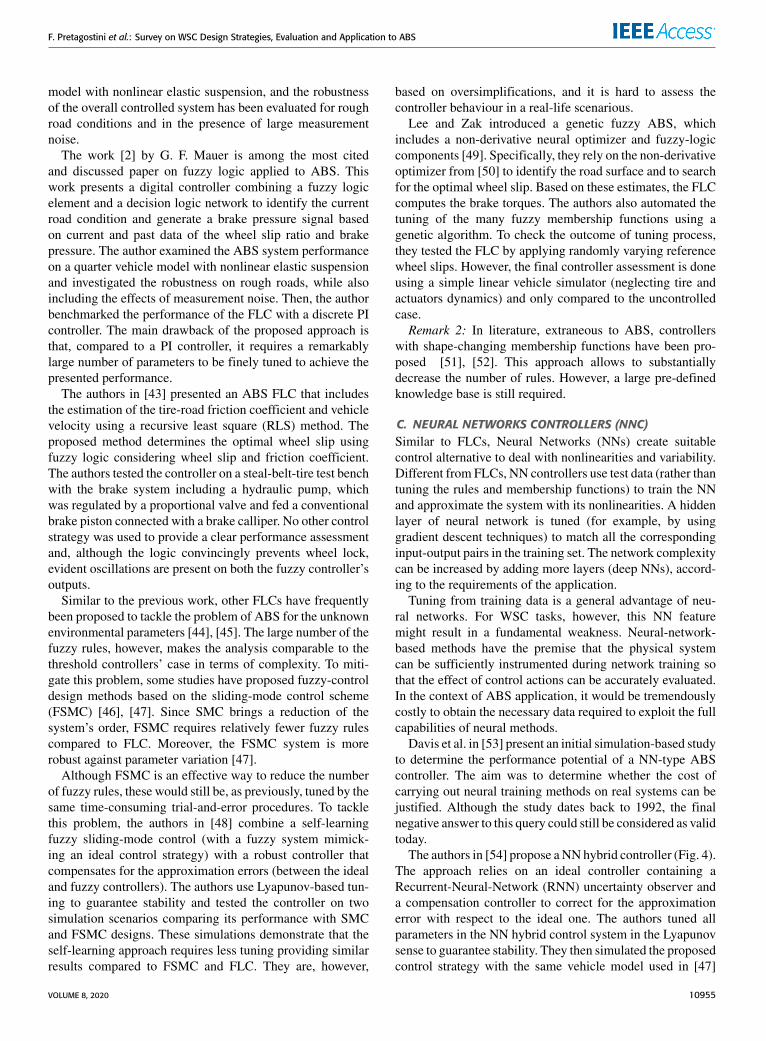
The authors in [54] propose aNNhybrid controller (Fig. 4).The approach relies on an ideal controller containing aRecurrent-Neural-Network (RNN) uncertainty observer anda compensation controller to correct for the approximationerror with respect to the ideal one. The authors tuned allparameters in the NN hybrid control system in the Lyapunovsense to guarantee stability. They then simulated the proposedcontrol strategy with the same vehicle model used in [47]
VOLUME 8, 2020 10955

F. Pretagostini et al.: Survey on WSC Design Strategies, Evaluation and Application to ABS
FIGURE 4. Neural network hybrid controller (adapted from [54]).
and compared the performance to a SMC design. In thissimplified setting, the proposed design showed good track-ing performance and robustness for various road conditions.In addition to this, the SMCoutperforms theNN-based designin terms of braking distance. Several additional studies onNNapplied to ABS can be found, for example, in [55] and [56].
D. PROPORTIONAL INTEGRAL DERIVATIVE (PID)CONTROLLERSPID controllers are among the most used controllers in theindustry. Fig. 5 details the general architecture of a PIDcontroller as applied to a generic ABS. The proportional,integral, and derivative gains can be tuned to ensure thatthe desired system performance is being achieved around adesired operating point. These controllers, however, do notgenerally provide optimal control action and might showinsufficient performance if the gains are poorly tuned (e.g.,overshoots, oscillations, or cycling around the set-point) orwhen they are in the presence of constraint saturation.
FIGURE 5. Generic ABS PID controller scheme.
PIDs are feedback controllers and do not rely on anyknowledge of the system dynamics (only input-outputbehaviour is considered). This could be an advantage in gen-eral, but it can also lead to reactive behaviour. Additionally,PID controllers do not cope well enough with nonlinearities(e.g., actuator saturation) compared to another control tech-niques, require trade-offs between regulation and responsetime, do not react to changes in the process behaviour, and hasa lag in the response to large disturbances. A further poten-tial problem is that derivative term (D) can amplify processnoise. Some of these issues can be mitigated. For example,low-pass filtering could be a solution to minimize the noiseamplification when using the derivative term. The derivativeaction and the filtering, however, could have counter-actionbehaviour. Therefore, the amount of filtering should be lim-ited, and low-noise instrumentation could be important [57].Anti-wind-up techniques can be used to deal with actuatorsaturation.
In the context of ABS regulation problem, PID controllerscould not achieve best performance under varying operatingconditions due to the aforementioned issues. In this respect,several investigations evaluated the use of PID (either insimulation or with hardware-in-the-loop tests) and supportthe conclusion of the proposed paper [43], [44]. Nevertheless,several strategies are available and can effectively improveboth performance and robustness of PID approach in ABSapplications, as discussed below.
The differential band can be turned off with a relative lossof performance but with benefit for robustness increase. Gainscheduling based on vehicle velocity allows the controller tohave high gains when the wheel dynamics is slow (higherspeeds) and low gains as it becomes faster (as the speeddecreases).
Augmenting the PI with sliding modes allows the con-troller to reduce its sensitivity to variation of road condi-tions (where oscillatory behaviour might occur). The authorsin [58] discussed this last approach proposing a sliding-modePI (SMPI). They implemented the design on a dSPACE pro-cessor board mounted on vehicle demonstrator equipped withEHB. They relied on standard wheel speed sensors and IMUfor the state and parameter estimation (i.e., vehicle speed,brake lining friction coefficient, tire forces). The algorithmsin closed-loop with the state estimator were tested. Addi-tionally, to evaluate the advantages of the developed con-trollers over state of the art solutions, the also implemented athreshold-based algorithm. Both the properly tuned PI and theSMPI were found to be superior to threshold-based control onhigh- and low-friction cases. Additionally, SMPI leads to a3-5% reduction in brake distance and a significant improve-ment in robustness compared to the PI.
Another option is to augment the PI controller (or anyother feedback-only controller) with a feedforward termto improve the bandwidth of the regulation scheme. Thisidea has been investigated on a simple quarter car modelin [59]. The authors used a cascaded wheel slip controlstrategy based on both wheel slip estimation and wheel
10956 VOLUME 8, 2020

F. Pretagostini et al.: Survey on WSC Design Strategies, Evaluation and Application to ABS
acceleration measurement. Additionally, they applied a set-point filter to smooth the response and improve control per-formance. This latest approach, however, is not always robustto sudden set point changes, which are commonly encoun-tered in real ABS scenarios. Nonetheless, it was analyti-cally demonstrated that the algorithm is able to globally andasymptotically stabilize the wheel slip around any prescribedset point.
Lastly, a mixed slip-deceleration control was introducedin [18]. The basic idea of this control approach is to select theregulated variable as a convex combination of the wheel slipand wheel deceleration. This strategy could be both powerfuland flexible as it could reduce the detrimental effects of inac-curate wheel slip estimation, while avoiding the limitationsof wheel acceleration control.
E. LQR CONTROLSimilar to PID controllers, linear quadratic regulators (LQR)are feedback controllers and are among themost popular opti-mal control approaches. Loosely speaking, they deal with theproblem of finding a state-feedback control law for a givenlinear time-invariant (LTI) system to satisfy an optimalitycriterion.
The classical LQR feedback law is given by
u (t) = −R−1BTPT x (t) . (1)
The control law is obtained by solving a quadratic opti-mization problem of the following form
min
∞∫t0
(u (t)T Ru (t)+ x (t)T Qx (t)
)dt (2)
where R is a positive-definite weighting matrix,Q is positive-semidefinite weighting matrix, and P is the solution ofthe algebraic Riccati equation associated with the systemdescribed by:
x (t) = Ax (t)+ Bu (t) , x (t0) = x0 (3)
where A and B are matrices of appropriate dimensionsdescribing LTI system of wheel slip dynamics.
This method is generally suitable to control multi-input-multi-output (MIMO) systems. MIMO systems show strongcouplings between states and, therefore, require tailoredstrategies to design the manoeuvre and achieve good perfor-mance. These systems often display significant nonlinearitiesor have non-minimum phase. Compared to PID controllers,LQR approaches require a model of the system to be con-trolled that might be complex and expensive to obtain.
Concerning ABS control, the explicit LQR approach takenby Johansen et al. is [60] of interest. Their work on thetopic extends on the previous research discussed in [40]. Thecontrol design relies on local linearization and gain schedul-ing. The proposed control law contains no explicit frictionmodel and relies on integral action, rather than adaptation,to eliminate a steady-state uncertainty. Following the LQR
theory, they formulate the optimality condition as a standardquadratic cost function resulting in the optimal control input:
u (t) = −R−1BT (v)PT︸ ︷︷ ︸K (v)
x (t) (4)
where P is the solution of the algebraic Riccati equation.The controller gain, namely K(v), depends on the speed. Gainscheduling is achieved by letting
dQ (v)dv
> 0, (5)
which reduces the gain as v → 0. This is necessary toavoid instability due to the unmodeled dynamics tending todominate as the velocity decreases and open loop wheel slipdynamics becomes faster. The authors proved that the controlstrategy is uniformly exponentially stable by using Lyapunovtheory. The vehicle implementation, however, showed funda-mental limitations on the achievable performance and maxi-mum gain that could be tolerated before becoming unstable.
This issue has been handled in [61] by discretising andaugmenting the controller with electro-mechanical brake-actuator dynamics and communication delays. The improvedmodel is used for the synthesis of gain matrices at appropriateoperating points, which are stored to provide an explicitpiece-wise linear controller that incorporates actuator rateconstraints. The controller is evaluated on various road con-ditions with different set-points. Several weak points areidentified, for example, the initial transient response was notsatisfactory due to significant modelling inaccuracies andnoise in the low-slip region. Tests on wet tarmac partiallycovered with ice-simulating material revealed the controlleris sensitive to friction coefficient variations and reacts withsignificant variability in the wheel slip error.
F. SLIDING MODE CONTROLSliding mode control (SMC) is a type of variable structurecontrol system and it is characterized by a switching controlaction, as the system crosses a certain manifold in the statespace, to force the state to reach, and thereafter to remain ona specified surface, called the sliding surface (Fig. 6). Thesystem dynamics, when confined to the sliding surface, aretermed as an ideal sliding motion and results in reduced-orderdynamics with respect to the original plant. The reductionprovides attractive advantages, such as insensitivity to param-eter variations, matched uncertainties and disturbances.
Although slidingmode control was demonstrated as a pow-erful control method for ABS application [62]–[64], it hassome disadvantages. In theory, the control action switch-ing would occur at infinitely high frequency. As a result,the trajectories of the dynamic system are moving along therestricted slidingmode subspace. In practice, it is not possibleto change the control infinitely fast because of time delays dueto software and hardware limitations. Therefore, the slidingmode control action can lead to a high frequency oscillation,or chattering, that excites unmodelled dynamics. This could
VOLUME 8, 2020 10957

F. Pretagostini et al.: Survey on WSC Design Strategies, Evaluation and Application to ABS
FIGURE 6. SMC ABS controller (adapted from [62]).
lead to energy loss, system instability, and excessive actuatorwear [65], [66].
Different techniques were introduced to reduce chatteringinABS design. Thesemethods smooth the discontinuous con-trol law to achieve a trade-off between control-bandwidth andtracking precision. The simplest method is to replace the sign-function in the hitting control part with a saturation functionor by other suitable continuous functions [67]. While thesemodifications are effective to reduce the chattering, thesechanges affect the tracking performance of the controllerand do not ensure asymptotic stability. As an alternative,the authors of [68] proposed to replace the sign-functionwith a PI-like expression in a fixed neighbourhood aroundthe switching surface. The authors of [69] proposed, instead,an improved continuous switching function that incorporatesthe state trajectory approach angle with respect to the slidingsurface. In this way, the overall SMC guarantees asymp-totic stability with a slight amount of system chattering.Harifi et al. in [70] used an integral switching surface, insteadof sign function, to reduce chattering. In this case, how-ever, the authors assume precise estimate on the bounds ofthe parametric uncertainties for the controller to work effi-ciently. Additionally, to suppress chattering conditional inte-grators [71] or offline optimization of the controller gains [72]have been also investigated.
SMC guarantees asymptotic stability in the presence ofmatched disturbances. In the case of unmatched disturbancesonly bounded stability can be guaranteed [73]. The authorsof [74] analysed the robustness to uncertainties related totire-road interaction of several SMC sliding surfaces forWSCin two-wheeled vehicles. The authors of [75] focused onthese uncertainties, as well, by using a grey systemmodellingapproach applied to SMC. This approach achieved enoughreduction of wheel slip oscillations even in cases of signifi-cant road friction variation.
The authors of [76] proposed a SMC augmented with aRadial Basis Function (RBF) NN. The RBFNN comprisesof a two-layer data processing structure, implementing amoving sliding surface. The adaptive rule is employed foronline adjustment of the RBF weights by using the reachingcondition of a specified sliding surface. Unlike conventionalSMC, the dynamic sliding surface moves to the desiredsliding surface from the initial condition, and thus the pro-posed design can achieve good tracking performance. The
strategy can eliminate the reaching phase from conventionalSMC, reduce chattering, and guarantee the system robustnessduring the whole control process. However, the approachis limited by the previously discussed drawbacks of NN inABS. The authors of [77] developed a SMC using a secondorder switching surface for wheel slip control. Second-orderSMC generalizes the basic sliding mode idea acting directlyon the second-order time derivative of the sliding variable.This method, with respect to the first-order case, provideshigher accuracy and generates continuous control actionswhile retaining the same robustness properties and a com-parable design complexity. Additionally, by means of sim-ulation, the method is proven to avoid complex stick-slipphenomena as no oscillations or overshoot take place duringthe transients. The authors claimed that it is not necessary tohave precise values for the error signals for the controller towork. However, on a real system, the approach requires thefirst and second-order derivatives of the slip signal, which isalready difficult to obtain reliably. Lastly, in contrast to first-order SMC, actuator dynamics cannot be considered.
The authors of [78] deployed a Pseudo-Sliding Modeapproach for the design of a mixed slip-deceleration con-troller, well explained in [79], as well. The SMC frame-work allows to alleviate the control sensitivity to the actuatorcharacteristic uncertainty, exhibited by the linear approachseen in [18]. The control architecture considers a morerealistic, first-order LTI system to model the behaviourof electro-mechanical brakes resulting in nonlinear brakingdynamics in contrast to [18], where a transfer function basedon the linearized model description was employed. However,the approach relies on the Burckhardt-type tire model, thatis, tire dynamics are not present, and the oversimplifiedsimulation is not representative of the controller absoluteperformance. Nonetheless, it is appropriate for showing thesuperiority of SMC over PI in both dynamic performance andnoise rejection.
The authors of [58] proposed an Integral SlidingMode (ISM) controller and demonstrated that ISM providescompensation and estimation of the perturbations with lesschattering compared to the SMPI. Compared to the switchingthreshold-based control, the approach reduces the brakingdistance by 31% and 25% with and without reference adap-tation respectively, on the low friction road surface. Theshortest stopping distance achieved by ISM control was 7%shorter than with PI and 2% shorter than SM (all with refer-ence adaptation logic in the loop). Furthermore, the authorsshowed the robustness of the system by comparing the vari-ations in braking distance of five subsequent tests: switchingthreshold-based causes deviation in 9% from the medianvalue, while for the ISM case this was reduced up to 3%. Theeffectiveness of the reference adaptation algorithm results ina reduction in braking distance of up to 2% in comparison tothe cases with pre-set reference wheel slip. This confirms thehypothesis that, during the emergency braking, the optimalarea of the λ-Fx friction curve can deviate from its initialvalue and emphasizes the importance of reference adaptation.
10958 VOLUME 8, 2020

F. Pretagostini et al.: Survey on WSC Design Strategies, Evaluation and Application to ABS
G. CLASSICAL ROBUST CONTROLH∞ control designs are robust control approaches. A robustcontrol design explicitly deals with uncertainty to achieverobust performance and stability in the presence of boundedmodelling errors. In contrast with an adaptive control, robustcontrol is designed to work in a static way, rather thanadapting to measurements of variations. An H∞ controlleris designed through optimizing the infinite norm of a perfor-mance index in H∞ space. By minimizing the sensitivity of asystem over its frequency spectrum, this design can guaranteethat the system will not greatly deviate from expected tra-jectories in the presence of disturbances. Finding an optimalH∞ controller is often both numerically and theoreticallycomplicated, as discussed in [80].
FIGURE 7. Design method based on mixed sensitivity (adapted from [81]).
Fig. 7 shows a general scheme of the approach, where r , e,n, d and y are the reference input, tracking error, measurementnoise, disturbance input and system output, respectively.W1,W2 andW3 are the weight functions of the performance of thesystem, output constraints of the controller and the systemrobustness, respectively. The H∞ mixed sensitivity controlconsists in choosing the weighting function W1, W2 and W3in the frequency domain such that condition (6) is satisfied,where Q, R, T are the transfer functions from r to e, u and yrespectively. ∥∥∥∥∥∥
W1QW2RW3T
∥∥∥∥∥∥∞
≤ 1 (6)
The authors in [81] proposed H∞ robust controllersdesigned via a simplified ABSmathematical model by mixedsensitivity method. They design the controller according tothe nominal plant model to keep the controlled system steadyand the H∞ norm of the sensitivity function small. Thecontroller is evaluated in simulation environment with a quar-ter car model. The manoeuvre represents friction transitionsuch as a µ-transition, and satisfactory performance has beenachieved.
In the context of robust control, a possible option is touse Linear Matrix Inequalities (LMIs) to approximate andsolve robust control problems in a more tractable form. In thecontext of ABS designs, the authors of [82] proposed a robustcontrol method using a Linear Parameter Varying (LPV)system representation and used LMIs to derive conditionsfor the existence of the state-feedback controller. They used
as plant model a quarter car model with Pacejka’s MagicFormula (MF).
The authors of [83] relied on a similar LMI technique toavoid the chattering effect in the design of a SMC controller.In particular, thework considers the system unmatched uncer-tainties in the design of ABS system by employing LMIs todesign a stable sliding surface. Compared to the approachesdescribed in the SMC Section, this method incorporatesuncertainties in the design phase. The proposed controller hasbeen investigated on a quarter car model showing that robuststabilisation and chattering reduction can be achieved.
H. MODEL PREDICTIVE CONTROLSimilar to optimal control, model predictive control (MPC)relies on optimization to find the optimal control input toapply to the plant. In contrast to LQR, MPC solves onlinea constrained Optimal Control Problem (OCP) over a finitetime window, called prediction horizon. An example of gen-eral OCP is described below:
min
t0+Tp∫t0
∥∥y (t)− yref (t)∥∥2Q + ∥∥u (t)− uref (t)∥∥2R+∥∥y (t0 + Tp)− yref (t0 + Tp)∥∥2P︸ ︷︷ ︸
J
x (t0) = x0 initial conditions
x (t) = f (x (t) , u (t)) plant dynamics
y (t) = g (x (t) , u (t)) output mapping
xmin ≤ x (t) ≤= xmax state constraint
umin ≤ u (t) ≤= umax actuator constraint (7)
The solution of the OCP is the result of minimizing thecost function J over the horizon Tp. Q and P are positivesemidefinite weight matrices penalizing the deviations of theoutputs y from their reference values yref and R is positivedefinite weight matrix penalizing the deviations of the inputsu from their reference values uref . The weight matrices areusually tuning parameters with a physical interpretation.
In contrast to LQR, MPC works over a finite time hori-zon to make the constrained optimization problem tractableonline (it would be computationally impossible to solve aconstrained infinite horizon problem with an infinite amountof decision variables and constraints). MPC formulates aparametric optimization problem, in which the parametersare the current states x0 of the system. Based on the currentsystem states, by using a dynamic model to describe thesystem (plant dynamics), the controller computes a sequenceof optimal control commands that minimizes J and satisfiesthe state and actuator constraints. Only the first element of theobtained control sequence is applied to the plant, accordingto the receding horizon principle. Every time the controllerreceives new measurements from the plant the process isrepeated. TheMPC problem formulation can be either convexor nonconvex and can accommodate both linear or nonlinearplant models and constraints. The general structure of a dis-crete time model predictive controller for wheel slip controlis shown in Fig. 8.
VOLUME 8, 2020 10959

F. Pretagostini et al.: Survey on WSC Design Strategies, Evaluation and Application to ABS
FIGURE 8. General structure of model predictive control.
MPC has the advantages of incorporating constraints andaccurately predicting (if an accurate model of the systemis available) the change of system dynamics along theprediction horizon. Robust MPC [84] implementations arealso possible (and involved the use of constraint-tighteningmethods [85], tubes [86], or chance-constraints [87]). Themain drawback of MPC is related to the computationalrequirements for online computation that could make theimplementation of the controller for real-time applicationschallenging or even impossible. For linear systems and poly-topic constraints, the MPC problem reduces to a quadraticprogramming problem, which can be solved efficiently.The computation load substantially increases when dealingwith nonlinear systems and non-convex constraints. Efficientonline solvers (such as IPOpt [88] and QPOASES [89]) havebeen developed for these formulations, but they only provideconvergence to local minima. In addition to this, the compu-tation time is often unpredictable, which could be a problemfor safety critical real-time applications.
Nonetheless, there have been attempts in using MPC forABS applications. Anwar et al., reiterating on what wasproposed for yaw dynamics control in [90], a generalized pre-dictive ABS control based on a Controlled Auto RegressiveIntegrated Moving Average model [91].
The authors of [92] proposed the Independent ModelGeneralized Predictive (IMGPC) control introduced byRossiter [93] for ABS control. The control system is testedon a simple linearized quarter-car model (with an unspecifiedtire model) in the presence of severe disturbances and noise.Their results showed that, with a long prediction horizon(500 samples), MPC performed better than LQR in termsof noise and disturbance rejection. The online computationalload is not mentioned in these studies.
The authors of [94] showed an optimization-based braketorque control law. The prediction model is obtained froma quarter car model equipped with Dugoff non-linear tiremodel augmented with a first-order transfer function for
the tire dynamics and first order actuator dynamics (EMB).To increase the robustness of the controller, they augmentedthe state with the integral of the wheel slip. They also anal-ysed the effect of the continuous time prediction horizon onthe tracking error. They found that, as the prediction horizonincreases the tracking error decreases up to a point, in whichthe control energy becomes oscillatory and chattering occurs.The proposed controller demonstrates better performancecompared to the controller with the SMC algorithm from [67]on dry and slippery roads including uncertainty levels of thetotal vehicle mass and the friction coefficient.
The authors of [95] took a step forward from simulationto HIL experiments. They proposed a distributed wheel-slipcontroller using MPC using a longitudinal vehicle model(a quarter car model) as prediction model assuming thateach wheel remains on the same road surface. The pre-defined longitudinal slip stiffness is used to compute thelongitudinal force. Tire relaxation dynamics is included inMPC formulation. The constrained optimal control problemis solved online with primal-dual method of the Hildreth’squadratic programming algorithm. The controller evaluationis performed on high-, mid-, and low µ surfaces and for eachof them the wheel slip error is found to be relatively smalland oscillations, although present, are confined. The mainlimitation is that longitudinal slip stiffness is predefined for agiven road surface.
The investigation [96] proposed the design of linear andnonlinear model predictive controllers (solved using ForcesPro [97]) incorporating a predefined MF tire model for wheelslip control using friction brake system and near-wheel elec-tric motors. The simulation-based assessment is performedusing an IPG/Carmaker vehicle model for various road sur-faces and µ-split braking showing accurate tracking perfor-mance and robustness against tire-road friction coefficientuncertainty. During µ variation a notable offset from thereference wheel slip is observed due to the predefined MFparameters, which requires adaptation of the internal model.
To overcome real-time capability issue related to MPC,the usage of explicit nonlinear MPC could be potential solu-tion assuming availability of a high-fidelity model on thedesign stage. The authors of [98] proposed an original explicitnonlinearMPC solution evaluated in EHBHIL test bench andIPG/Carmaker model with first-order transient tire dynamics,and compared to PID ABS. This solution outperforms PIDABS resulting in 11.4% decrease in the brake distance forlow µ conditions. The needs to update the predefined tiremodel in the controller can be considered as the limitationsimilar to the previous research.
I. DISCUSSIONBased on the state of the art, the following conclusions canbe derived:• Threshold-based (rule-based) algorithms compose thevast majority of ABS controllers found on today’s vehi-cles but are time-consuming and supplier-dependent totune due to their heuristic nature and a large list of
10960 VOLUME 8, 2020

F. Pretagostini et al.: Survey on WSC Design Strategies, Evaluation and Application to ABS
tuning parameters. Additionally, considering the recentimprovements in actuator technology and trend towardsthe coordinated chassis control, their potential is signif-icantly underused.
• Controllers based on fuzzy logic suffer from similarissues, such as the large number of tuning parameters,membership functions, and rules, which increase expo-nentially with the complexity of the application. In gen-eral, fuzzy approaches are good for those processes that,although containing uncertainty, do not present the largevariability band intrinsic to the ABS regulation problem.For a controller addressing everyday situations in accor-dance with the ABS safety requirements, thousands ofrules would be needed, and it would be extremely incon-venient, if even possible, to tune them. This conclusion iscontradictory to the conclusions performed in the surveyin 2011 [35].
• Neural networks approaches require a very large setof training data to achieve adequate performance androbustness. For the WSC tasks, this is extremely con-suming in terms of time and resources.
• PIDs struggle with nonlinearities and can become unsta-ble if countermeasures are not in place (e.g., anti-windupstrategies).
• LQRmethods are feedback controllers sensitive to mod-elling errors and do not accommodate any feedforwardaction that could be beneficial for ABS applications.
• SMC demonstrates better performance and robustnessthan the PID. SMCs combined with methods that allowto reduce chattering (e.g., the ISMC) are the best reactivewheel slip controllers in this regard. SMCs approaches,however, are still rarely validated by real-world exper-iments. Finally, similar to LQR, SMC is a feedbacktechnique and adding feedforward action is nontrivial,limiting the performance of the controller.
• Classical robust control approaches allow to dealwith disturbances and noise by design; however,the performance evaluation of ABS controllers usingthese approaches is limited compared to othermethods.
• Model predictive control is a promising approach thatoffers space for improvements in terms of performanceand robustness with respect to state of the art con-trollers. Compared to other designs, MPC also proposesa modular framework that it is intuitive to understandand maintain. The main limitation of MPC is relatedto the computational burden, especially if the con-trol problem is nonconvex. Nevertheless, the advancein microcontrollers processing power, solvers fornonconvex optimization, and the drive towards amodel-based integrated chassis control will mitigate thisdrawback.
• Several control methods such as iterative learning [99],backstepping [100], nonlinear feedback control [101]and flatness-based [102] were not considered in thispaper due to limited studies for WSC application.
TABLE 1. Summary of control strategies.
• Lastly, one of the weak-investigated directions and inthe starting point of the research in WSC is the usage ofreinforcement learning [103], [104] and deep learning.
A summary of the analysed control strategies is presentedin the Table 1 using Harvey Balls.
Based on the considerations above, MPC should be furtherinvestigated by the research community to understand itsfull capabilities. This motivates the case study proposed inSection IV. Current trends related to automated driving result-ing in the usage of on-board high-performance computationalprocessors that the major drawback of an MPC approach,computational effort, is decreasing in importance and couldbe outweighed by its performance benefits.
III. ABS TESTING AND KEY PERFORMANCE INDICATORSTo assess the controller’s performance, its behaviour shouldbe comparedwith the state of the art solutions. Demonstratingthe stability of the ABS controller is also a key point thatremains unsolved. Classical stability theory to validate suchcomplex designs is extremely difficult to apply. Traditionalapproaches can only prove closed-loop stability of the systemmodel used in the analysis and not the real plant. In theory,this would require developing high-fidelity models of thesystem in differential equation forms. In practice, derivingthese models is too difficult.
To overcome these issues, a comprehensive set of manoeu-vres should be used to empirically demonstrate the stabilityof the developed design. Moreover, a set of key performanceindicators (KPIs) is proposed to analyse and interpret theresults. Selecting the right manoeuvres and KPIs is not trivialand requires extensive evaluation of regulations and tech-nical documents. The aim of this section is to summarizethis research to simplify the future design evaluations. Theproposed manoeuvres and KPIs are discussed below.
A. ABS TESTING SCENARIOSThe goal of the manoeuvre selection is to span all pos-sible conditions that might be encountered on the road.
VOLUME 8, 2020 10961

F. Pretagostini et al.: Survey on WSC Design Strategies, Evaluation and Application to ABS
Attention is therefore focused on identifying a restricted setof manoeuvres that is representative of a much larger set ofpossible conditions. Braking scenarios were chosen basedon the guidelines given by the United Nations in Regulation13 (E/ECE/- TRANS/505/Rev.1/Add.12/Rev.8. 3. RegulationNo. 13) and Toyota’s internal knowledge.
The eight selected manoeuvres, reported in Table 2,belongs to three major groups:
TABLE 2. ABS straight-line test scenarios.
Braking on smooth roads – Three manoeuvres are targetedat evaluating the performance gain on smooth roads withconstant friction conditions. Three friction levels are selected,associated with dry asphalt, wet asphalt and packed snow.The initial speed for each of three decelerations is chosen forrelatable domains’ speed limits (e.g. high-way, freeway, etc.)and advisable maximum speed associated with the frictioncondition.Friction transition – The three µ-transition manoeuvres
(performed on smooth roads) are specifically intended forevaluation of the controller transient behaviour. Friction tran-sitions are commonly found on everyday roads and it istherefore key for the controller to be fast adapting and robustto them. To assess the controller behaviour in relation totransient conditions, two friction transitions in which the fric-tion coefficient drops and one in which it raises are typicallysimulated. The speed at which the transition happens can beselected based on typical operational conditions for a givenvehicle.Braking on rough roads – Two last manoeuvres are per-
formed on rough surface. The objective is to quantify andcompare eventual performance degradation when injectinghigh-noise levels in the sensed signals. Road irregularities,in fact, are transmitted through the vehicle and cause variableband noise on the sensor measurement. As frequency andamplitude are dependent on the road shape, it is usuallydifficult to filter the disturbance out.
Extra test procedures related to µ-split conditions are notconsidered in this paper.
B. KEY PERFORMANCE INDICATORSDifferent KPI sets have been selected for each of three groupsof manoeuvres.Steady state and transient performances, as well as human
factors and actuator wear, are evaluated on smooth roads bythe following KPIs:
ABS Index of Performance(ABSIP) – this KPI compares thebraking distance achieved by the specific controller to that ofthe case in which ABS is not present. The returned value,a brake distance reduction percentage, gives a first roughidea of how effective the controller is throughout the brakingmanoeuvre:
ABSIP =dABSdskid
(8)
Brake Distance(BD) – the KPI is calculated as the velocityintegral from the moment, at which the brake pedal is firstpressed ti, to that, in which the vehicle speed equals to the exitvelocity tf reported in Table 2. The aim is also to compareoverall braking performance but this time with an absolutebrake distance:
BD =
tf∫ti
Vxdt (9)
Mean Fully Developed Deceleration(MFDD) – this KPI issimply the mean longitudinal acceleration, ax , calculated in atime interval that goes from 90% to 5% of the vehicle speedV0 at the beginning of the braking. The MFDD is specificallydesigned for assessment the vehicle deceleration performancethroughout the entire ABS activation time.
MFDD = [ax]0.9V00.05V0
(10)
ABS efficiency(ηABS ) – this KPI is the ratio of mean lon-gitudinal acceleration to its theoretical maximum (productbetween average friction coefficient µ and gravitational con-stant g). ax is calculated from when the vehicle velocityequals 80% of its initial speed to when the vehicle is at5% of its initial speed. This KPI is specifically designedfor assessment of steady state deceleration performance. Thesteady state covers the interval after the initial weight transferup to the point at which the ABS switched to its low speedmode and pressure modulation is stopped.
ηABS =[ax]
0.8V00.05V0
µg(11)
Peak to Peak (PTP or ωpeak ) – KPI quantifies the agilityof the controller in transient conditions. This is done byfocusing only on the first control cycle after ABS activationand it is calculated in a similar fashion to a normalized sliperror except that the vehicle velocity is not needed for thecalculation and thus simulation results can be replicated moreeasily in real life. ωmax,k is the wheel angular velocity ateither ABS activation or friction transition. ωopt,k , on theother hand, is the optimal wheel speed obtained from the tiremodel. An illustration of these two wheel speeds is shownin Fig. 9.
ωpeak =∑
k
ωmax,k − ωopt,k
ωmax,kk = [FL,FR] ∧ [RL,RR] (12)
10962 VOLUME 8, 2020

F. Pretagostini et al.: Survey on WSC Design Strategies, Evaluation and Application to ABS
FIGURE 9. Illustration of the Peak to Peak KPI (PTP).
Integral Time-weighted Average of the longitudinal jerk(ITAEJx ) – KPI aims at characterizing driving comfort. Anegative influence on the driver’s perception during ABSbraking occurs owing to fluctuations in the realized brakeforce, which produces oscillations in the vehicle deceleration.Here, the lower the vehicle jerk, the better the comfort char-acteristics provided by the ABS are. Weighting the averagewith time, corresponds to taking the area between the jerksignal jx and zero (an ideal value). Additionally, taking theintegral has the important advantage of filtering out outliersand spikes (commonly originated by differentiating a noisysignal as their contribution to the area is zero). In this waythe signal does not require complex filtering.
ITAEJx =
tf∫ti
t |jx | dt (13)
Integral torque variation – Actuator wear (IACATb ) – KPIcalculates how much torque variation is prescribed by thecontroller. This is important for a first evaluation of potentialissues related to actuator wear. Large torque variation canlead to premature degradation of both brake components andvalves. Estimating how much this number should be consid-ered as critical is outside the scope of the proposed work.
IACATb =
tf∫ti
∑k
∣∣Tb,k ∣∣dtk = [FL,FR,RL,RR] (14)
Integral Pitch Variation (IPV) – this KPI relates to thehuman factors. The driver capability to estimate distance issignificantly deteriorated in the presence of excessive vehiclepitch angle ϕ [105]. Therefore, it is desirable for an ABS to beas smooth as possible during the control action. IPV is mostlyrelevant on high friction surfaces due to larger load transfercausing high variation of pitch angle.
IPV =
tf∫ti
|ϕ| dt (15)
KPIs used for the friction transitions scenarios are focusedon analysing the controller behaviour after µ-transition. Heretwo key aspects are transient performance and lateral stability.The indices are as follows:Recovery time (Trec)−− KPI quantifies how much time is
taken by the controller to recover from the friction transitionand go back to steady state conditions. The counter is startedwhen the front wheels first experience the change in surfacecondition and runs until the longitudinal acceleration is insidea certain band. The band is identified as ±5% of the meanlongitudinal accelerationax after the transition.
Trec = [t]±5%axi,jump (16)
Peak to peak at friction transition(ωpeak,jump)−− the focusis only on the first control cycle after the friction transition.Generally, the depth of the first cycle significantly affects theABS performance, and it is therefore highly important to tryminimizing this specific aspect. The metric is of particularinterest (i) for lower friction coefficients where the cycletakes significantly more time, and (ii) for under-braking, todemonstrate the recovery from the unstable part of the λ-Fxfriction curve. It is calculated in the same way as for ωpeak .Mean deceleration at friction transition (ax,jump)−− KPI
targeted at quantifying the overall deceleration performanceduring the friction transitions. The calculation starts 0.2sbefore the front wheels experience the change in friction andends 1s after the rear wheels have performed the transition.
ax,jump =
tf ,jump+1∫ti,jump
axdt (17)
Maximum yaw rate at friction transition (ψmax) − − KPIaims at quantifying the vehicle stability during the frictionµ- transition manoeuvre. It is not uncommon for a vehicleexperiencing a sudden change in friction to exhibit someyawing. Yaw angles are usually not high since the wheel pairsundergo the friction transition at the same time. Nonetheless,the velocity at which the vehicle rotate should be contained inorder to allow the driver to counter steer. The usual thresholdfor acceptability is set around a value of 1 − 1.5 deg/s.
ψmax = max[ψ]f ,jumpi,jump (18)
For rough roads, the indicators are the same as that intro-duced for smooth roads.
For the evaluation of µ-split testing, brake distance, vehi-cle deceleration, maximum yaw rate and corrective steeringangle are typically used.
IV. CASE STUDY: A NONLINEAR MODEL PREDICTIVECONTROL ABS DESIGNMotivated by the conclusions in Section II.I, the proposedcase study investigates the use of nonlinear model predictivecontrol (NMPC) for ABS applications. The paper goal is toshow the potential of this technique compared to the currentindustry-used threshold-based logic in the scenarios and with
VOLUME 8, 2020 10963

F. Pretagostini et al.: Survey on WSC Design Strategies, Evaluation and Application to ABS
the KPIs discussed in the previous section. First, to useNMPC, a model that accurately describes the dynamics ofthe system needs to be defined:
λFL =1Vx
[rwIw
(dT cmdb,FLτ + Tb,FL − Fx,FLrw
)−
1− λFL0.5mf + msaxh/2L
]λFR =
1Vx
[rwIw
(dT cmdb,FRτ + Tb,FR − Fx,FRrw
)−
1− λFR0.5mf + msaxh/2L
]λRL =
1Vx
[rwIw
(dT cmdb,RLτ + Tb,RL − Fx,RLrw
)−
1− λRL0.5mr − msaxh2L
]λRR =
1Vx
[rwIw
(dT cmdb,RRτ + Tb,RR − Fx,RRrw
)−
1− λRR0.5mr − msaxh/2L
]Tb,FL = dTb,FLTb,FR = dTb,FRTb,RL = dTb,RLTb,RR = dTb,RR
ax =(Fx,FL + Fx,FR + Fx,RL + Fx,RR
)/ms (19)
where Fx,ij is the longitudinal tire force, ax is the longitudinalacceleration, Vx is the chassis velocity, Iw is the wheel inertia,L is the the wheel base, rw is the effective rolling radius,ms is the sprung mass, mf and mr are the portions of thetotal mass resting on the front and rear axles, respectively.The first four equations describe the wheel slip dynamicsof each wheels λij. Additional four augmentation equationsTb,ij allow the MPC to control the torque rate dTb,ij insteadof the brake torque. Finally, the last equation describes thechassis longitudinal dynamics. The model also considers theeffects related to the brake actuator dynamics and longitudi-nal weight transfer. In particular, the EHB system behaviouris represented by a first-order dynamics with the time con-stant τ , and the longitudinal weight transfer is approximatedby its static part. Finally, online wheel force data is used(obtained from the load sensing bearings including accuracyand noise level [31]) to formulate a complete description ofthe tire dynamics. The state vector is given by the following:
x =[λFL , λFR, λRL , λRR,Tb,FL ,Tb,FR,Tb,RL ,Tb,RR,Vx
]T(20)
The control commands (i.e., the brake torque rates, dT cmdb,ij )can be obtained by solving the associated optimal controlproblem that includes the model described above as the pre-diction model and the constraints discussed below.
Table 3 summarizes the state and input constraints. Thesebounds were selected according to the following reasons:
TABLE 3. State and input bounds.
TABLE 4. Important controller settings.
• The lower bound for the chassis velocity is set to 0 toprevent the vehicle from going backwards, while theupper-bound is selected equal to the vehicle’s maximumspeed.
• The brake torque lower bound is 0 Nm given thatnegative numbers would mean that a driving torque isapplied. The upper bound is the system’s maximumcapability. Given the different sizing of front and rearbrakes, two values are listed in Table 3.
• Given that the EHB pressure increase rate is approx-imately 1300 bar/s and assuming the system is 30%slower in damping pressure based on the previous inves-tigations [106], the torque rate is limited for the consid-ered vehicle. For stability reasons it is advisable for rearwheels to follow the front ones in the event of a lock up.Hence, the rear-pressure increase rate of the rear axle islowered.
The tool used as modelling environment to define theoptimal control problem is ACADO Toolkit. ACADO is anopen-source software environment for dynamic optimizationwhich supports self-contained C code [107]. Its most appeal-ing features is the task scheduling of the Real Time Itera-tion (RTI) scheme which splits one iteration into two phases:a preparation phase, where the NLP is linearized, discretizedand condensed; and a feedback phase, where the condensedQP is solved. Since operations are parametric in the initialstate x0, the preparation can be done offline. In this way,the solver can achieve real-time performance within the milli-or micro-seconds range (depending on the application) [89].The NMPC problem reduces to a dense QP that ACADOsolves by using qpOASES [108]. Table 4 reports the mostrelevant settings of the solver.
As mentioned, NMPC is the key element of the proposedABS formulation. Nevertheless, other components are alsoimportant for the correct behaviour of the design under dis-cussion. Fig. 10 provides an overview of the overall controlstructure.
10964 VOLUME 8, 2020

F. Pretagostini et al.: Survey on WSC Design Strategies, Evaluation and Application to ABS
FIGURE 10. Proposed ABS controller scheme.
TABLE 5. Weight scheduling.
The reference wheel slip generator reads the longitudi-nal and normal forces (Fx,ij and Fz,ij, respectively) at eachtime step and, after calculating the friction coefficient µij,outputs the reference wheel slips λd based on a 3D-mapobtained from tire testing conducted by Toyota. The sliptarget, together with other signals coming from the vehi-cle and driver subsystems, are then passed to the activationlogic.
The activation logic is responsible for cycling throughthree possible controller states: (i) ABS Off, (ii) ABS On,and (iii) ABS On - Low Speed. A state machine selectsthe controller’s mode and target state. Whenever the ABS isinactive the NMPC acts as a driver brake request follower.Activation of the ABS controller is triggered based on somepredefined wheel deceleration thresholds for front and rearwheel pairs. In a range from 1 m/s to Vmax , the ABS operatesas a slip target follower. Below 1 m/s, where the wheeldynamics is too unstable to control, the brake torque is keptconstant to avoid any under-braking.
Based on the selected control mode, the online weightadjustment logic selects the entries of the weight matrices Q,P and R (where R is equal to Q). In this formulation Q andP are diagonal matrices containing state weights and controlweights respectively (Table 5). When the driver is in control(ABS off), theMPC is forced to track the driver demand usingthe weight entries from Table 5.
When the ABS is working in normal mode, the controlleracts as a wheel slip reference tracker. Since the vehiclevelocity acts as a time-scale factor for the slip dynamics,cost weights are defined to track the slip target with an
increasingly larger control effort to cope with the progres-sively higher slip frequency. Weight functions ff (Vx) andfr (Vx) are two monotonically decreasing functions.In low speed ABS mode, the brake torque applied to
each wheel is kept constant to prevent any unwanted under-braking. To achieve it, the brake torques and rates are beingprioritized.
The NMPC receives the current state, target state, onlineforce measurements and cost weights to calculate the opti-mal actuator commands, that are, the brake torques. Theoptimized brake torques are then used as the target forthe low-level ABS controller, which directly operates thehydraulic unit. Individual wheel pressures are then appliedto the vehicle to close the control loop.
The performance of the proposed NMPC controller wascompared to an industry-used threshold-based controller.Fig. 11 shows the high-end simulation setup used forevaluation.
FIGURE 11. Vehicle co-simulation layout.
Each of the main vehicle subsystems was developed in theappropriate simulation tool, namely, MATLAB/Simulink forthe controller, Simpack multi-body software for the vehiclemodel, Dymola multi-physics simulation software for thebrake system and Delft-Tyre MF-SWIFT (Short WavelengthIntermediate Frequency Tire) model for tire behaviour. Themodels were then interconnected to replicate full vehiclebehaviour.
The vehicle model was validated against a large set ofexperimental data collected by Toyota. The compliance ofthe flexible bodies were measured on dedicated test benches.The hydraulics of the brake system behaviour was replicatedfollowing a multi-physics approach. The pad-disc frictioncoefficient was modelled by a look-up table, whose val-ues depended on vehicle velocity, pressure and tempera-ture. The relationship was obtained by analysing test datafor friction coefficient measurement according to the SAEJ2522 standard (known as AK Master). More advancedapproaches for pad-disc interaction can be based on dynam-ical models, e.g. [109], [110], or finite element modelling,e.g. [111]–[113].
Finally, to reproduce sensor behaviour, the informationcoming from the simulation is altered to match the signalquality.
VOLUME 8, 2020 10965

F. Pretagostini et al.: Survey on WSC Design Strategies, Evaluation and Application to ABS
TABLE 6. Friction transition dry-wet – KPI values.
Eight ABS braking scenarios were evaluated according tothe test manoeuvres presented in Section III. In particular,the results are presented for (i) friction transition from dry-wet, (ii) smooth dry asphalt, and (iii) packed snow. A fullanalysis for (ii) and a spider plot summarizing the findings for(i) – (iii) are presented. More details regarding the performedanalysis is given in [114].
FIGURE 12. Friction transition dry-wet time histories – NMPC.
Fig. 12 presents the results for friction transition. As thefigure shows, once the controller becomes active, the frontbrake torques increase to take advantage of the longitudinalweight transfer, while rear ones decrease. When the vehiclestarts to pitch back, the behaviour is reversed. Steady statewould eventually be reached; however, at 2.5 s the frictiontransition occurs, and brake torques promptly reduce. Thepredictive behaviour of the NMPC controller allows (i) thesystem to limit the under-braking and (ii) the torques con-verge to their optimal value net of vehicle pitching.
The comparison between the wheel speeds and vehi-cle speed (Fig. 12) highlights the absence of the typicalthreshold-based ABS control cycles (i.e., increase, decrease,and hold pressure). The longitudinal slip distribution graph
FIGURE 13. KPIs for straight-line braking.
of the front-left wheel (bottom plots) shows how the slip iscontained in a narrow band close to its optimal value. Twodefined peaks are observed, each associated with a specific
10966 VOLUME 8, 2020

F. Pretagostini et al.: Survey on WSC Design Strategies, Evaluation and Application to ABS
friction coefficient. Moreover, limited distribution of longi-tudinal slip outside the stable area of the force-slip curve isidentified.
Using the above-mentioned KPIs, Table 6 summarizesthe obtained results. The minimum longitudinal accelerationat the transition reveals considerably less under-braking inresponse to the friction change for the NMPC controller com-pared to the threshold-based controller. Similarly, the timeneeded to regain steady state is also noticeably less. As aresult, the mean deceleration value is sizably higher. Peak-to-peak metrics show how the first control cycle after thetransition, is deeper for the benchmark. Lastly, although lat-eral stability is retained in both cases, the maximum yawrate underlines the superiority of the NMPC design over thethreshold-based one.
The summary of KPIs is shown in Fig. 13a. Front and rearpeak-to-peak indicators were 78% and 50% lower respec-tively. Less torque variations also ensure a much shortertransition time (38% shorter). Lastly, an effect to keep undercontrol regardless of the longitudinal transition performanceis themaximum yaw rate. In this case the NMPC ensures 50%more yawing stability than the benchmark.
Fig. 13b shows the relative results for the dry asphalt brak-ing from 130km/h to 0km/h. In this scenario, the NMPCmainadvantage is in the absence of first cycle overshoot, as par-ticularly evident from the peak-to-peak indicators (approx.50% better compared to the benchmark). Nevertheless, as amuch larger portion of the braking manoeuvre is spent instationary conditions, fewer percentage points of differencein steady-state performance also correspond to a remarkableimprovement. The brake distance is reduced by more than30% by the NMPC.
Jerk and pitch related indicators reveal an effect relatedto human factors (20% and 8% of the improvement corre-spondingly compared to the benchmark logic). The IACAdemonstrates reduction of actuator wear (approx. 9% of theimprovement).
Fig. 13c shows the relative results for the packed snowbraking from 40km/h to 0km/h. Steady state performanceindicators related to the proposed control were about 25%higher than the benchmark. The NMPC utilized more frictioncompared to the rule-based controller, increasing ABS effi-ciency. Jerk and pitch rate metrics are improved by approx.65% and reduction of actuator wear (IACA) is improvedby 29%.
V. CONCLUSIONBased on the presented state of the art in ABS controldesigns, it was decided to further investigate NMPC as a casestudy and compare it to the industry-used threshold-basedcontrol. To evaluate the proposed controller, a methodologysimilar to the industry-used assessment chain was applied:(i) a restricted set of manoeuvres were evaluated coveringall possible ABS control fall-backs; (ii) a comprehensiveset of key performance indicators (KPIs) was developed;(iii) a high-fidelity simulation setup (multibody vehicle
model, rigid ring tire model, brake model, brake-pad inter-action, etc.) was deployed to accurately replicates the brak-ing behaviour from the field tests both at the vehicle leveland actuator dynamics. The analysis showed that the pro-posed logic generally outperforms the threshold-based con-trol on each of the simulated manoeuvres. The improvementsare mainly due to a much smoother and precise controlaction. The NMPC destabilizes the wheel dynamics muchless than the benchmark logic with its repeated control cycles(increase, decrease, and hold pressure). Additionally, therewas a large improvement in the transient behaviour obtainedwith the NMPC controller. This was due to predictive natureof the controller. On average, the NMPC controller was ableto improve by 75%, the first ABS control cycle, compared tothe threshold-based controller. Similarly, following a transi-tion in the friction coefficient, the NMPC was approximately50% faster to recover from the friction transition. The NMPCcontroller improved the steady-state tracking by an averageof 15%. Moreover, the NMPC controller also enhanced occu-pants’ comfort up to 20% and reduced actuator wear by upto 30%. Regarding computational expenses, the proposedNMPC controller did not encounter any issues related tothe solver failing to find a solution. Only minor real-timeconcerns at the beginning of the braking manoeuvre wereobserved as well as for the first few milliseconds after a fric-tion transition occurred. Therefore, computational aspects arestill open to future investigations. Lastly, the proposed NMPCrequires a considerably lower number of tuning parameters(roughly two order of magnitude lower than the equivalentthreshold-based logic).
REFERENCES[1] K. Reif, Brakes, Brake Control and Driver Assistance Systems: Function,
Regulation and Components. Weisbaden, Germany: Springer-Vieweg,2014.
[2] G. Mauer, ‘‘A fuzzy logic controller for an ABS brakingsystem,’’ IEEE Trans. Fuzzy Syst., vol. 3, no. 4, pp. 381–388,Nov. 1995.
[3] L. Austin and D. Morrey, ‘‘Recent advances in antilock braking systemsand traction control systems,’’ Proc. Inst. Mech. Eng., D, J. AutomobileEng., vol. 214, no. 6, pp. 625–638, Jun. 2000.
[4] J. Wilkinson, C. W. Mousseau, and T. Klingler, ‘‘Brake response timemeasurement for a HIL vehicle dynamics simulator,’’ SAE Tech. Paper0148-7191, Apr. 2010.
[5] D. Wu, H. Ding, K. Guo, and Z. Wang, ‘‘Experimental research on thepressure following control of electro-hydraulic braking system,’’ SAETech. Paper 0148-7191, Apr. 2014.
[6] S. Choi, J. Lee, and I. Hwang, ‘‘New generation ABS using lin-ear flow control and motor speed control,’’ SAE Trans., pp. 237–242,2003.
[7] J. Yao and W. Deng, ‘‘Active disturbance rejection adaptive control ofhydraulic servo systems,’’ IEEE Trans. Ind. Electron., vol. 64, no. 10,pp. 8023–8032, Oct. 2017.
[8] Z. Yao, J. Yao, and W. Sun, ‘‘Adaptive RISE control of hydraulic systemswith multilayer neural-networks,’’ IEEE Trans. Ind. Electron., vol. 66,no. 11, pp. 8638–8647, Nov. 2019.
[9] Y. Gao and M. Ehsani, ‘‘Electronic braking system of EV And HEV–integration of regenerative braking, automatic braking force control andABS,’’ SAE Trans., pp. 576–582, Oct. 2010.
[10] J. Ko, S. Ko, H. Son, B. Yoo, J. Cheon, and H. Kim, ‘‘Development ofbrake system and regenerative braking cooperative control algorithm forautomatic-transmission-based hybrid electric vehicles,’’ IEEE Trans. Veh.Technol., vol. 64, no. 2, pp. 431–440, Feb. 2015.
VOLUME 8, 2020 10967

F. Pretagostini et al.: Survey on WSC Design Strategies, Evaluation and Application to ABS
[11] J. Zhang, C. Lv, J. Gou, and D. Kong, ‘‘Cooperative control of regenera-tive braking and hydraulic braking of an electrified passenger car,’’ Proc.Inst. Mech. Eng., D, J. Automobile Eng., vol. 226, no. 10, pp. 1289–1302,Oct. 2012.
[12] N. Mutoh, ‘‘Driving and braking torque distribution methods for front-and rear-wheel-independent drive-type electric vehicles on roads withlow friction coefficient,’’ IEEE Trans. Ind. Electron., vol. 59, no. 10,pp. 3919–3933, Oct. 2012.
[13] C. Lv, J. Zhang, Y. Li, and Y. Yuan, ‘‘Novel control algorithm of brakingenergy regeneration system for an electric vehicle during safety–criticaldriving maneuvers,’’ Energy Convers. Manage., vol. 106, pp. 520–529,Dec. 2015.
[14] Z. Zhang, R. Ma, L. Wang, and J. Zhang, ‘‘Novel PMSM control for anti-lock braking considering transmission properties of the electric vehicle,’’IEEE Trans. Veh. Technol., vol. 67, no. 11, pp. 10378–10386, Nov. 2018.
[15] D. Savitski, V. Ivanov, K. Augsburg, T. Emmei, H. Fuse, H. Fujimoto,and L. Fridman, ‘‘Wheel slip control for the electric vehicle with in-wheelmotors: Variable structure and sliding mode methods,’’ IEEE Trans. Ind.Electron., to be published.
[16] R. De Castro, R. E. Araújo, M. Tanelli, S. M. Savaresi, and D. Freitas,‘‘Torque blending and wheel slip control in EVs with in-wheel motors,’’Vehicle Syst. Dyn., vol. 50, no. 1, pp. 71–94, Jan. 2012.
[17] M. Gerard, W. Pasillas-Lépine, E. De Vries, and M. Verhaegen, ‘‘Adap-tation of hybrid five-phase ABS algorithms for experimental validation,’’IFAC Proc. Volumes, vol. 43, no. 7, pp. 13–18, Jul. 2010.
[18] S. M. Savaresi, M. Tanelli, C. Cantoni, D. Charalambakis, F. Previdi,and S. Bittanti, ‘‘Slip-deceleration control in anti-lock braking systems,’’IFAC Proc. Volumes, vol. 38, no. 1, pp. 103–108, 2005.
[19] W. Pasillas-Lépine, ‘‘Hybrid modeling and limit cycle analysis for a classof five-phase anti-lock brake algorithms,’’ Vehicle Syst. Dyn., vol. 44,no. 2, pp. 173–188, Feb. 2006.
[20] S. M. Savaresi andM. Tanelli, Active Braking Control Systems Design forVehicles. London, U.K.: Springer-Verlag, 2010.
[21] B. J. Ganzel, ‘‘Slip control boost braking system,’’ U.S. Patents 20080 284 242 A1 Nov. 20, 2008.
[22] K. Berntorp, ‘‘Joint wheel-slip and vehicle-motion estimation based oninertial, GPS, and wheel-speed sensors,’’ IEEE Trans. Control Syst. Tech-nol., vol. 24, no. 3, pp. 1020–1027, May 2016.
[23] W.-Y. Wang, I.-H. Li, M.-C. Chen, S.-F. Su, and S.-B. Hsu, ‘‘Dynamicslip-ratio estimation and control of antilock braking systems using anobserver-based direct adaptive fuzzy-neural controller,’’ IEEE Trans. Ind.Electron., vol. 56, no. 5, pp. 1746–1756, May 2009.
[24] D. Nesic, A. Mohammadi, and C. Manzie, ‘‘A framework for extremumseeking control of systems with parameter uncertainties,’’ IEEE Trans.Autom. Control., vol. 58, no. 2, pp. 435–448, Feb. 2013.
[25] C. Lee, K. Hedrick, and K. Yi, ‘‘Real-time slip-based estimation of max-imum tire-road friction coefficient,’’ IEEE/ASME Trans. Mechatronics,vol. 9, no. 2, pp. 454–458, Jun. 2004.
[26] Z. Qi, S. Taheri, B. Wang, and H. Yu, ‘‘Estimation of the tyre–roadmaximum friction coefficient and slip slope based on a novel tyre model,’’Vehicle Syst. Dyn., vol. 53, no. 4, pp. 506–525, Apr. 2015.
[27] V. Ivanov, B. Shyrokau, D. Savitski, J. Orus, R. Meneses,J.-M. Rodríguez-Fortún, J. Theunissen, and K. Janssen, ‘‘Designand testing of ABS for electric vehicles with individually controlledon-board motor drives,’’ SAE Int. J. Passenger Cars-Mech. Syst., vol. 7,no. 2, pp. 902–913, Aug. 2014.
[28] A. T. Van Zanten, R. Erhardt, K. Landesfeind, and G. Pfaff, ‘‘VDCsystems development and perspective,’’ SAE Trans., pp. 424–444, 1998.
[29] U. Kiencke and L. Nielsen, Automotive Control Systems: For Engine,Driveline, and Vehicle, 2nd ed. Berlin, Germany: Springer-Verlag, 2005.
[30] S. Kerst, B. Shyrokau, and E. Holweg, ‘‘Reconstruction of wheel forcesusing an intelligent bearing,’’ SAE Int. J. Passenger Cars-Electron. Elect.Syst., vol. 9, no. 1, pp. 196–203, Apr. 2016.
[31] S. Kerst, B. Shyrokau, and E. Holweg, ‘‘A model-based approach for theestimation of bearing forces and moments using outer ring deformation,’’IEEE Trans. Ind. Electron., vol. 67, no. 1, pp. 461–470, Jan. 2020.
[32] K. B. Singh, M. Ali Arat, and S. Taheri, ‘‘An intelligent tire based tire-road friction estimation technique and adaptive wheel slip controller forantilock brake system,’’ J. Dyn. Syst., Meas., Control, vol. 135, no. 3,2013, Art. no. 031002.
[33] M. Corno, M. Gerard, M. Verhaegen, and E. Holweg, ‘‘Hybrid ABScontrol using force measurement,’’ IEEE Trans. Control Syst. Technol.,vol. 20, no. 5, pp. 1223–1235, Sep. 2012.
[34] S. Kerst, B. Shyrokau, and E. Holweg, ‘‘Anti-lock braking control basedon bearing load sensing,’’ in Proc. EuroBrake, Dresden, Germany, 2015,pp. 4–6.
[35] A. A. Aly, E.-S. Zeidan, A. Hamed, and F. Salem, ‘‘An antilock-brakingsystems (ABS) control: A technical review,’’ Intell. Control Automat.,vol. 2, no. 3, p. 186, 2011.
[36] V. Ivanov, D. Savitski, and B. Shyrokau, ‘‘A survey of traction controland antilock braking systems of full electric vehicles with individuallycontrolled electric motors,’’ IEEE Trans. Veh. Technol., vol. 64, no. 9,pp. 3878–3896, Sep. 2015.
[37] R. B. GmbH., K. Reif, and K.-H. Dietsche, Automotive Handbook.Gerlingen, Germany: Robert Bosch, 2014.
[38] M. Vignati and E. Sabbioni, ‘‘Force-based braking control algorithm forvehicles with electric motors,’’ Vehicle Syst. Dyn., pp. 1–19, Jun. 2019.
[39] A. G. Ulsoy, H. Peng, and M. Çakmakci, Automotive Control Systems.Cambridge, U.K.: Cambridge Univ. Press, 2012.
[40] T. Johansen, J. Kalkkuhl, J. Ludemann, and I. Petersen, ‘‘Hybrid con-trol strategies in ABS,’’ in Proc. Amer. Control Conf., vol. 2, 2001,pp. 1704–1705.
[41] I. Ait-Hammouda and W. Pasillas-Lépine, ‘‘On a class of eleven-phaseanti-lock brake algorithms robust with respect to discontinuous tran-sitions of road characteristics,’’ IFAC Proc. Volumes, vol. 37, no. 21,pp. 551–556, Dec. 2004.
[42] J. Layne, K. Passino, and S. Yurkovich, ‘‘Fuzzy learning control forantiskid braking systems,’’ IEEE Trans. Control Syst. Technol., vol. 1,no. 2, pp. 122–129, Jun. 1993.
[43] J. Cabrera, A. Ortiz, J. Castillo, and A. Simon, ‘‘A fuzzy logic control forantilock braking system integrated in the IMMa tire test bench,’’ IEEETrans. Veh. Technol., vol. 54, no. 6, pp. 1937–1949, Nov. 2005.
[44] W. Lennon and K. Passino, ‘‘Intelligent control for brake systems,’’ IEEETrans. Control Syst. Technol., vol. 7, no. 2, pp. 188–202, Mar. 1999.
[45] V. G. Ivanov, V. B. Algin, and B. N. Shyrokau, ‘‘Intelligent control forABS application with identification of road and environmental proper-ties,’’ Int. J. Vehicle Auton. Syst., vol. 4, no. 1, p. 44, 2006.
[46] S.-W. Kim and J.-J. Lee, ‘‘Design of a fuzzy controller with fuzzy slidingsurface,’’ Fuzzy Sets Syst., vol. 71, no. 3, pp. 359–367, May 1995.
[47] C.-M. Lin and C.-F. Hsu, ‘‘Self-learning fuzzy sliding-mode control forantilock braking systems,’’ IEEE Trans. Control Syst. Technol., vol. 11,no. 2, pp. 273–278, Mar. 2003.
[48] B.-J. Choi, S.-W. Kwak, and B. K. Kim, ‘‘Design of a single-input fuzzylogic controller and its properties,’’ Fuzzy Sets Syst., vol. 106, no. 3,pp. 299–308, Sep. 1999.
[49] Y. Lee and S. Zak, ‘‘Designing a genetic neural fuzzy antilock-brake-system controller,’’ IEEE Trans. Evol. Comput., vol. 6, no. 2, pp. 198–211,Apr. 2002.
[50] S. Baglio, L. Fortuna, S. Graziani, and G. Muscato, ‘‘Membership func-tion shape and the dynamic behaviour of fuzzy systems,’’ Int. J. Adapt.Control Signal Process., vol. 8, no. 4, pp. 369–377, Jul. 1994.
[51] B. N. Shyrokau and V. G. Ivanov, ‘‘Alterable fuzzy sets in automotivecontrol applications,’’ Int. J. Model., Identificat. Control, vol. 3, no. 3,pp. 305–307, 2008.
[52] G. Kokes and T. Singh, ‘‘Adaptive fuzzy logic control of an anti-lockbraking system,’’ inProc. IEEE Int. Conf. Control Appl., vol. 1, Jan. 2003,pp. 646–651.
[53] L. Davis, G. Puskorius, F. Yuan, and L. Feldkamp, ‘‘Neural networkmodeling and control of an anti-lock brake system,’’ in Proc. Intell.Vehicles Symp., Jan. 2003, pp. 179–184.
[54] C.-M. Lin and C.-F. Hsu, ‘‘Neural-network hybrid control for antilockbraking systems,’’ IEEE Trans. Neural Netw., vol. 14, no. 2, pp. 351–359,Mar. 2003.
[55] A. Poursamad, ‘‘Adaptive feedback linearization control of antilockbraking systems using neural networks,’’ Mechatronics, vol. 19, no. 5,pp. 767–773, Aug. 2009.
[56] J. O. Pedro, O. A. Dahunsi, and O. T. Nyandoro, ‘‘Direct adaptive neuralcontrol of antilock braking systems incorporated with passive suspensiondynamics,’’ J. Mech. Sci. Technol., vol. 26, no. 12, pp. 4115–4130,Dec. 2012.
[57] Y. Li, K. H. Ang, and G. C. Y. Chomg, ‘‘PID control system analysis anddesign: Problems, remedies, and future directions,’’ IEEE Control Syst.Mag., vol. 26, no. 1, pp. 32–41, Feb. 2006.
[58] D. Savitski, D. Schleinin, V. Ivanov, and K. Augsburg, ‘‘Robust continu-ous wheel slip control with reference adaptation: Application to the brakesystem with decoupled architecture,’’ IEEE Trans. Ind. Informat., vol. 14,no. 9, pp. 4212–4223, Sep. 2018.
10968 VOLUME 8, 2020

F. Pretagostini et al.: Survey on WSC Design Strategies, Evaluation and Application to ABS
[59] T. Johansen, I. Petersen, J. Kalkkuhl, and J. Ludemann, ‘‘Gain-scheduledwheel slip control in automotive brake systems,’’ IEEE Trans. ControlSyst. Technol., vol. 11, no. 6, pp. 799–811, Nov. 2003.
[60] T. A. Johansen, I. Petersen, and O. Slupphaug, ‘‘Explicit sub-optimallinear quadratic regulation with state and input constraints,’’ Automatica,vol. 38, no. 7, pp. 1099–1111, Jul. 2002.
[61] I. Petersen, ‘‘Wheel slip control in ABS brakes using gain scheduledoptimal control with constraints,’’ Ph.D. dissertation, Norwegian Univ.Sci. Technol., Trondheim, Norway, 2003.
[62] M.-C. Wu and M.-C. Shih, ‘‘Simulated and experimental study ofhydraulic anti-lock braking system using sliding-mode PWM control,’’Mechatronics, vol. 13, no. 4, pp. 331–351, May 2003.
[63] S. Drakunov, U. Ozguner, P. Dix, and B. Ashrafi, ‘‘ABS control usingoptimum search via sliding modes,’’ IEEE Trans. Control Syst. Technol.,vol. 3, no. 1, pp. 79–85, Mar. 1995.
[64] A. Will, S. Hui, and S. Zak, ‘‘Sliding mode wheel slip controller for anantilock braking system,’’ Int. J. Vehicle Des., vol. 19, no. 4, pp. 523–539,1998.
[65] H. Sira-Ramírez, ‘‘On the sliding mode control of nonlinear systems,’’Syst. Control Lett., vol. 19, no. 4, pp. 303–312, 1992.
[66] P. Wellstead and N. Pettit, ‘‘Analysis and redesign of an antilock brakesystem controller,’’ IEE Proc.-Control Theory Appl., vol. 144, no. 5,pp. 413–426, Sep. 1997.
[67] K. R. Buckholtz, ‘‘Reference input wheel slip tracking using slidingmodecontrol,’’ SAE Trans., pp. 477–483, 2002.
[68] C. Unsal and P. Kachroo, ‘‘Sliding mode measurement feedback controlfor antilock braking systems,’’ IEEE Trans. Control Syst. Technol., vol. 7,no. 2, pp. 271–281, Mar. 1999.
[69] K. Buckholtz, ‘‘Approach angle-based switching function for slidingmode control design,’’ in Proc. Amer. Control Conf., vol. 3, May 2002,pp. 2368–2373.
[70] A. Harifi, A. Aghagolzadeh, G. Alizadeh, and M. Sadeghi, ‘‘Designinga sliding mode controller for slip control of antilock brake systems,’’Transp. Res. C, Emerg. Technol., vol. 16, no. 6, pp. 731–741, Dec. 2008.
[71] R. De Castro, R. E. Araujo, and D. Freitas, ‘‘Wheel slip control of EVsbased on sliding mode technique with conditional integrators,’’ IEEETrans. Ind. Electron., vol. 60, no. 8, pp. 3256–3271, Aug. 2013.
[72] T. Shim, S. Chang, and S. Lee, ‘‘Investigation of sliding-surface design onthe performance of sliding mode controller in antilock braking systems,’’IEEE Trans. Veh. Technol., vol. 57, no. 2, pp. 747–759, Mar. 2008.
[73] X. Han, E. Fridman, and S. Spurgeon, ‘‘Sliding-mode control of uncertainsystems in the presence of unmatched disturbances with applications,’’Int. J. Control, vol. 83, no. 12, pp. 2413–2426, Dec. 2010.
[74] M. Tanelli and A. Ferrara, ‘‘Enhancing robustness and performance viaswitched second order sliding mode control,’’ IEEE Trans. Autom. Con-trol., vol. 58, no. 4, pp. 962–974, Apr. 2013.
[75] E. Kayacan, Y. Oniz, and O. Kaynak, ‘‘A grey system modeling approachfor sliding-mode control of antilock braking system,’’ IEEE Trans. Ind.Electron., vol. 56, no. 8, pp. 3244–3252, Aug. 2009.
[76] Y. Jing, Y.-E. Mao, G. M. Dimirovski, Y. Zheng, and S. Zhang, ‘‘Adaptiveglobal sliding mode control strategy for the vehicle antilock brakingsystems,’’ in Proc. Amer. Control Conf., Jun. 2009, pp. 769–773.
[77] T. Kawabe, M. Nakazawa, I. Notsu, and Y. Watanabe, ‘‘A sliding modecontroller for wheel slip ratio control system,’’ Vehicle Syst. Dyn., vol. 27,nos. 5–6, pp. 393–408, Jun. 1997.
[78] C. Poussot-Vassal, ‘‘Discussion on: ‘Combining slip and decelerationcontrol for brake-by-wire control systems: A sliding-mode approach,’’’Eur. J. Control, vol. 13, no. 6, pp. 612–615, Jan. 2007.
[79] M. Tanelli, R. Sartori, and S. M. Savaresi, ‘‘Sliding mode slip-deceleration control for brake-by-wire control systems,’’ IFAC Proc.Volumes, vol. 40, no. 10, pp. 135–142, 2007.
[80] K. Glover and J. C. Doyle, ‘‘A state space approach to H∞ optimalcontrol,’’ in Three Decades of Mathematical System Theory. Berlin,Germany: Springer, 1989, pp. 179–218.
[81] Y. B. Yan, H. Wu, and W. Q. Wang, ‘‘Research on robust control of anti-locked braking system of vehicles,’’ Appl. Mech. Mater., vols. 543–547,pp. 1504–1509, Mar. 2014.
[82] S. Ç. Bas.lamis.li, İ. E. Köse, and G. Anlas, ‘‘Robust control of anti-lockbrake system,’’ Vehicle Syst. Dyn., vol. 45, no. 3, pp. 217–232, Mar. 2007.
[83] Y.-E. Mao, Y. Zheng, Y. Jing, G. M. Dimirovski, and S. Hang, ‘‘An LMIapproach to slip ratio control of vehicle Antilock braking systems,’’ inProc. Amer. Control Conf., Jun. 2009, pp. 3350–3354.
[84] A. Bemporad and M. Morari, ‘‘Robust model predictive control: Asurvey,’’ in Robustness in Identification and Control. London, U.K.:Springer, 1999, pp. 207–226.
[85] A. Richards and J. How, ‘‘Robust stable model predictive control withconstraint tightening,’’ in Proc. Amer. Control Conf., 2006, pp. 1–6.
[86] D. Q. Mayne, E. C. Kerrigan, E. J. Van Wyk, and P. Falugi, ‘‘Tube-based robust nonlinearmodel predictive control,’’ Int. J. Robust NonlinearControl, vol. 21, no. 11, pp. 1341–1353, Jul. 2011.
[87] F. Oldewurtel, C. N. Jones, and M. Morari, ‘‘A tractable approxi-mation of chance constrained stochastic MPC based on affine distur-bance feedback,’’ in Proc. 47th IEEE Conf. Decis. Control, Dec. 2008,pp. 4731–4736.
[88] A. Wächter and L. T. Biegler, ‘‘On the implementation of an interior-point filter line-search algorithm for large-scale nonlinear programming,’’Math. Program., vol. 106, no. 1, pp. 25–57, Mar. 2006.
[89] H. J. Ferreau, C. Kirches, A. Potschka, H. G. Bock, and M. Diehl,‘‘QpOASES: A parametric active-set algorithm for quadratic program-ming,’’Math. Program. Comput., vol. 6, no. 4, pp. 327–363, Dec. 2014.
[90] S. Anwar, ‘‘Yaw stability control of an automotive vehicle via gener-alized predictive algorithm,’’ in Proc. Amer. Control Conf., Aug. 2005,pp. 435–440.
[91] S. Anwar and B. Ashrafi, ‘‘A predictive control algorithm for an anti-lockbraking system,’’ SAE Trans., pp. 484–490, 2002.
[92] M. Hasankhansari, M. Yaghoobi, and A. Abaspour, ‘‘Independent modelgeneralized predictive controller design for antilock braking system,’’ Int.J. Comput. Appl., vol. 114, no. 1, pp. 18–23, Mar. 2015.
[93] G. Valencia-Palomo and J. Rossiter, ‘‘Programmable logic controllerimplementation of an auto-tuned predictive control based on minimalplant information,’’ ISA Trans., vol. 50, no. 1, pp. 92–100, Jan. 2011.
[94] H. Mirzaeinejad and M. Mirzaei, ‘‘A novel method for non-linear controlof wheel slip in anti-lock braking systems,’’ Control Eng. Pract., vol. 18,no. 8, pp. 918–926, Aug. 2010.
[95] D. K. Yoo and L. Wang, ‘‘Model based wheel slip control via constrainedoptimal algorithm,’’ in Proc. IEEE 22nd Int. Symp. Intell. Control,Oct. 2007, pp. 1239–1246.
[96] M. S. Basrah, E. Siampis, E. Velenis, D. Cao, and S. Longo, ‘‘Wheel slipcontrol with torque blending using linear and nonlinear model predictivecontrol,’’ Vehicle Syst. Dyn., vol. 55, no. 11, pp. 1665–1685, Nov. 2017.
[97] A. Zanelli, A. Domahidi, J. Jerez, and M. Morari, ‘‘FORCES NLP:An efficient implementation of interior-point methods for multistagenonlinear nonconvex programs,’’ Int. J. Control, vol. 93, no. 1,pp. 13–29, Jan. 2020.
[98] D. Tavernini, F. Vacca, M. Metzler, D. Savitski, V. Ivanov, P. Gruber,A. E. H. Karci, M. Dhaens, and A. Sorniotti, ‘‘An explicit nonlinear modelpredictive ABS controller for electro-hydraulic braking systems,’’ IEEETrans. Ind. Electron., to be published.
[99] C. Mi, H. Lin, and Y. Zhang, ‘‘Iterative learning control of antilockbraking of electric and hybrid vehicles,’’ IEEE Trans. Veh. Technol.,vol. 54, no. 2, pp. 486–494, Mar. 2005.
[100] J.-S. Lin and W.-E. Ting, ‘‘Nonlinear control design of anti-lock brakingsystems with assistance of active suspension,’’ IET Control Theory Appl.,vol. 1, no. 1, pp. 343–348, Jan. 2007.
[101] M. Tanelli, A. Astolfi, and S. M. Savaresi, ‘‘Robust nonlinear outputfeedback control for brake by wire control systems,’’ Automatica, vol. 44,no. 4, pp. 1078–1087, Apr. 2008.
[102] E. De Vries, A. Fehn, and D. Rixen, ‘‘Flatness-based model inversefor feed-forward braking control,’’ Vehicle Syst. Dyn., vol. 48, no. 1,pp. 353–372, Dec. 2010.
[103] M.-B. Radac and R.-E. Precup, ‘‘Data-driven model-free slip control ofanti-lock braking systems using reinforcement Q-learning,’’ Neurocom-puting, vol. 275, pp. 317–329, Jan. 2018.
[104] C. F. Verdier, R. Babuška, B. Shyrokau, and M. Mazo, Jr., ‘‘Near optimalcontrol with reachability and safety guarantees,’’ IFAC-PapersOnLine,vol. 52, no. 11, pp. 230–235, 2019.
[105] D. Cao, X. Song, andM. Ahmadian, ‘‘Editors’ perspectives: Road vehiclesuspension design, dynamics, and control,’’ Vehicle Syst. Dyn., vol. 49,nos. 1–2, pp. 3–28, Feb. 2011.
[106] B. Shyrokau, D.Wang, D. Savitski, K. Hoepping, and V. Ivanov, ‘‘Vehiclemotion control with subsystem prioritization,’’ Mechatronics, vol. 30,pp. 297–315, Sep. 2015.
[107] D. Ariens, B. Houska, H. Ferreau, and F. Logist. (2011). ACADO forMATLAB User’s Manual. Accessed: Dec. 20, 2019. [Online]. Available:http://acado.sourceforge.net/doc/pdf/acado_matlab_manual.pdf
VOLUME 8, 2020 10969

F. Pretagostini et al.: Survey on WSC Design Strategies, Evaluation and Application to ABS
[108] B. Houska, H. J. Ferreau, and M. Diehl, ‘‘An auto-generated real-timeiteration algorithm for nonlinear MPC in the microsecond range,’’ Auto-matica, vol. 47, no. 10, pp. 2279–2285, Oct. 2011.
[109] G. Ostermeyer, ‘‘On the dynamics of the friction coefficient,’’ Wear,vol. 254, no. 9, pp. 852–858, May 2003.
[110] B. Shyrokau, D. Wang, K. Augsburg, and V. Ivanov, ‘‘Vehicle dynamicswith brake hysteresis,’’ Proc. Inst. Mech. Eng., D, J. Automobile Eng.,vol. 227, no. 2, pp. 139–150, 2013.
[111] A. Belhocine and W. Z. W. Omar, ‘‘Three-dimensional finite elementmodeling and analysis of the mechanical behavior of dry contact slippingbetween the disc and the brake pads,’’ Int. J. Adv. Manuf. Technol., vol. 88,nos. 1–4, pp. 1035–1051, Jan. 2017.
[112] A. Belhocine, ‘‘FE prediction of thermal performance and stresses inan automotive disc brake system,’’ Int. J. Adv. Manuf. Technol., vol. 89,nos. 9–12, pp. 3563–3578, Apr. 2017.
[113] A. Belhocine and W. Z. W. Omar, ‘‘CFD analysis of the brake disc andthe wheel house through air flow: Predictions of Surface heat transfercoefficients (STHC) during braking operation,’’ J. Mech. Sci. Technol.,vol. 32, no. 1, pp. 481–490, Jan. 2018.
[114] F. Pretagostini, B. Shyrokau, and G. Berardo, ‘‘Anti-lock braking controldesign using a nonlinear model predictive approach and wheel informa-tion,’’ in Proc. IEEE Int. Conf. Mechatronics (ICM), vol. 1, Mar. 2019,pp. 525–530.
FRANCESCO PRETAGOSTINI received the B.Sc.degree in mechatronics from the University ofRome Tor Vergata, Italy, in 2016, and the M.Sc.degree (cum laude) in vehicle engineering fromthe Delft University of Technology, The Nether-lands, in 2018, with a focus on vehicle dynamicsand controls. He performed his thesis project inToyota Motor Europe, Belgium, on topics relatedto brake system design and advanced brake con-trollers. Since September 2018, he has been a Per-
formance Engineer with Ferrari, Italy, focusing on innovation topics relatedto advanced vehicle control, new sensor, and actuator development.
LAURA FERRANTI received the M.Sc. degree(cum laude) in control engineering from the Uni-versity of Rome Tor Vergata, Italy, in 2012, andthe Ph.D. degree in control engineering from theDelft University of Technology, The Netherlands,in 2017. She is currently an Assistant Professorwith the Cognitive Robotics Department, DelftUniversity of Technology. She has coauthored thebest paper in multirobot systems at the 2019 Inter-national Conference on Robotics and Automation
(ICRA). Her research interests include optimization and optimal control,model predictive control, embedded optimization-based control with appli-cation in flight control, maritime transportation, robotics, and automotive.
GIOVANNI BERARDO received theM.Sc. degree(cum laude) in mechanical engineering from theUniversity of Rome Tor Vergata, Italy, in 1998.In 2003, he joined Toyota Motor Europe takingvarious operational and management responsibil-ities in Europe and Japan, where he is in chargeof chassis systems of mass production vehicles.Since 2017, he has been managed the EuropeanTeam developing controls for the vehiclemotion ofconventional and automated driving vehicles. His
research interests include resistance of structures employed in oil and gastransportation, he moved to an engineering role in the automotive industry.
VALENTIN IVANOV received the Mech.Eng.,Ph.D., and D.Sc. degrees in automotive engineer-ing from the Belarusian National Technical Uni-versity, Minsk, Belarus, in 1992, 1997, and 2006,respectively, and the Dr.Ing. habil. degree in auto-motive engineering from the Technische Univer-sität Ilmenau (TUIL), Ilmenau, Germany, in 2017.From 1998 to 2007, he was an Assistant Profes-sor, an Associate Professor, and a Full Professorwith the Department of Automotive Engineering,
Belarusian National Technical University. He is currently the EuropeanProject Coordinator with the Automotive Engineering Group, TUIL. Hisresearch interests include vehicle dynamics, electric vehicles, automotivecontrol systems, and chassis design.
BARYS SHYROKAU received the Dipl.Eng.degree (cum laude) in mechanical engineeringfrom Belarusian National Technical University,Belarus, in 2004, and the joint Ph.D. degree incontrol engineering from Nanyang Technologi-cal University, Singapore, in 2015, and TechnicalUniversity Munich, Germany. He is currently anAssistant Professor with the Section of IntelligentVehicles, Department of Cognitive Robotics, DelftUniversity of Technology, The Netherlands. His
research interests are vehicle dynamics and control, motion comfort, anddriving simulator technology. He received the Scholarship and Award fromFISITA, DAAD, SINGA, ISTVS, and CADLM.
10970 VOLUME 8, 2020