Embed Size (px)
DESCRIPTION
k
Citation preview
Vehicle and Mission Control of the DELFIM Autonomous Surface Craft
J. Alves, P. Oliveira, R. Oliveira, A. Pascoal, M. Rufino, L. Sebastiao, C. SilvestreInstitute for Systems and Robotics, Instituto Superior Tecnico
Av. Rovisco Pais, 1046-001 Lisboa, Portugal{antonio, cjs, pjcro}@isr.ist.utl.pt
Abstract— DELFIM is an autonomous surface craft devel-oped at ISR/IST for automatic marine data acquisition andto serve as an acoustic relay between submerged craft and asupport vessel. The paper describes the navigation, guidance,and control systems of the vehicle, together with the missioncontrol system that allows end-users to seamlessly programand run scientific missions at sea. Practical results obtainedduring sea tests in the Atlantic, near Azores islands, are brieflysummarized and discussed.
I. I NTRODUCTION
The paper describes the vehicle and mission controlsystems of DELFIM, an autonomous surface craft (ASC)developed for automatic marine data acquisition and toserve as an acoustic relay between submerged craft and asupport vessel. The research and development effort thatled to the development of the ASC was initiated in thescope of the European MAST-III Asimov project which setforth the goal of achieving coordinated operation of theINFANTE autonomous underwater vehicle and the DELFIMASC, while ensuring fast data communications betweenthe two vehicles, see [1]. This concept is instrumental inenabling the transmission of sonar and video images througha specially developed acoustic communications channel thatis optimized to transmit in the vertical.
The DELFIM ASC can also be used as a stand-aloneunit, capable of maneuvering autonomously and performingprecise path following while carrying out automatic marinedata acquisition and transmission to an operating centerinstalled on board a support vessel or on shore. This is inline with the current trend to develop systems to lower thecosts and improve the efficiency of operating oceanographicvessels at sea. See [2], [3], [4] and the references therein.Conventional oceanographic vessels require a large supportcrew, are costly to operate, and their availability is oftenrestricted to short periods during the year. However, manyoceanographic missions consist of routine operations thatcould in principle be performed by robotic vessels capableof automatically acquiring and transmitting data to one ormore support units installed on shore. In the future, the useof multiple autonomous oceanographic vessels will allowresearchers to carry out synoptic studies of the ocean on timeand space scales appropriate to the phenomena under study.Furthermore, they will play a major role in enabling scientists
This work was supported by the Portuguese FCT POSI programme underframework QCA III and by the project MEDIRES of the AdI.
Fig. 1. The DELFIM Vehicle.
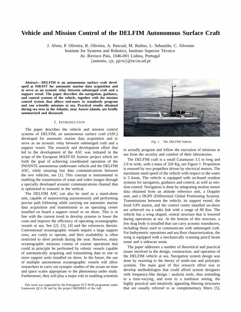
to actually program and follow the execution of missions atsea from the security and comfort of their laboratories.
The DELFIM craft is a small Catamaran 3.5 m long and2.0 m wide, with a mass of 320 Kg, see Figure 1. Propulsionis ensured by two propellers driven by electrical motors. Themaximum rated speed of the vehicle with respect to the wateris 5 knots. The vehicle is equipped with on-board residentsystems for navigation, guidance and control, as well as mis-sion control. Navigation is done by integrating motion sensordata obtained from an attitude reference unit, a Dopplerunit, and a DGPS (Differential Global Positioning System).Transmissions between the vehicle, its support vessel, thefixed GPS station, and the control centre installed on-shoreare achieved via a radio link with a range of 80 Km. Thevehicle has a wing shaped, central structure that is loweredduring operations at sea. At the bottom of this structure, alow drag body is installed that can carry acoustic transducers,including those used to communicate with submerged craft.For bathymetric operations and sea floor characterization, thewing is equipped with a mechanically scanning pencil beamsonar and a sidescan sonar.
The paper addresses a number of theoretical and practicalissues involved in the design, construction, and operation ofthe DELFIM vehicle at sea. Navigation system design wasdone by resorting to the theory of multi-rate and polytopicsystems. The main goal of this research effort was todevelop methodologies that could afford system designerswith frequency-like design / analysis tools, thus extendingto a time-varying, and even to a nonlinear setting, thehighly practical and intuitively appealing filtering structuresthat are usually referred to as complementary filters [5],
[6]. For Guidance and Control, a new methodology wasused that borrows from theory of gain-scheduled controlsystems exposed in [7], [8], [9]. At the Mission Controllevel, the work was focused on the development of softwareand hardware tools for mission programming and missionexecution of autonomous vehicles, including cooperativecontrol of surface and underwater vehicles. This work wasinstrumental in enhancing the capabilities of the Petri-netbased software application named CORAL, proprietary ofISR/IST, originally described in [1]. At the same time, hard-ware architectures were developed for distributed real-timecontrol of ocean robotic vehicles. Over the past few years,intensive series of tests at sea have shown the reliability ofthe overall Mission Control System (MCS) developed. TheDELFIM ASC has by now completed a long series of seabedmap building missions successfully, in a purely autonomousmode, under the supervision of its MSC. During a typicalmission the vehicle performs a grid survey, executing pathfollowing maneuvers in the presence of shifting sea currentsand wind, while collecting acoustic data from a sidescan anda mechanically scanning pencil beam sonar. The data arelater processed to obtain high resolution bathymetric mapsof the covered areas.
II. NAVIGATION , GUIDANCE, AND CONTROL
This section is an overview of the navigation, guidance,and control systems implemented on-board the DELFIMASC. Guidance and control system design relied on akinematic / dynamic model of the ASC. For navigationsystem design, a simple kinematic model was adopted. Theorganization of the section reflects the natural sequence ofsteps that were taken in the course of designing the abovesystems. Central to the design procedure is the developmentof a vehicle model that captures the kinematic equations ofmotion, together with inertial and hydrodynamic effects at adynamic level.
A. ASC Model
The ASC model was derived from basic principles ofphysics that borrow from the theory of rigid body motiondynamics and kinematics; see for example [8] and [10].System identification required a combination of theoreticaland experimental methods to determine the most importanthydrodynamic coefficients of the vehicle and the thrustercharacteristics. The estimated model for the DELFIM vehiclecan be found in [11], which contains a description of themethodologies used for modeling and identification.
The equations of motion for surface vehicles can beobtained from Newton-Euler laws following the classicalapproach described in [10]. A simple derivation based on ageneral set-up adopted in robotics [12] can be found in [8].Using that set-up, the equations are easily developed usinga global coordinate frame{I} and a body fixed coordinateframe{B} that moves with the ASC. The following notationis requiredp = [x, y]T - position of the origin of{B} expressed in{I}v = [u, v]T - linear velocity of the origin of{B} relative to{I} , expressed in{B}
ψ - Heading angle that describes the orientation of frame{B} with respect to{I}r - body fixed angular velocity of{B} relative to {I} ,expressed in{B}R = R(ψ) - rotation matrix from {B} to {I} ,parameterized byψ. R is orthonormal, satisfiesR = I forψ = 0 , and can be written as
R =[cos(ψ) − sin(ψ)sin(ψ) cos(ψ)
].
The extended vectorq = [u, v]T is obtained from the bodyfixed linear and angular velocity vectors. The input vectorn = [nsb, nps]T consists of the differential and commonmode of the speed of rotation of the main propellers. LetmandI be the mass and the moment of inertia of the vehicle,respectively. With this notation, the dynamics and kinematicsof the ASC can be written in condensed form as
MRB q + CRB(q) q = τ (q, q,n) (1)
p = R(ψ)v (2)
ψ = r (3)
whereτ denotes the vector of external forces and moments.The symbolsMRB andCRB denote the 2D rigid body inertiamatrix and the matrix of Coriolis and centripetal terms,respectively. The vectorτ can further be decomposed as
τ (q, q,n) = τ add(q, q) + τ body(q) + τ prop(q,n)
where τ add denotes added mass terms andτ body consistsof the hydrodynamic forces and moments acting on thevehicle’s body. The termτ prop represents the forces andmoments generated by the propellers. The effect of a constantcurrent can be simply modeled by re-writing the equationsabove in terms of relative velocity with respect to the water.In particular, the kinematic equation will yield
p = R(ψ)vw + w, (4)
wherevw is the body-axis relative velocity of the ASC withrespect to the water, andw is the water velocity in inertialframe{I} .
B. Guidance and Control
A number of missions with ASCs require the execution oftrajectory tracking (TT) and path following (PF) maneuvers.Trajectory tracking refers to the problem of making a marinevehicle track a time-parameterized reference curve in two-dimensional space. This requires that the velocity of thevehicle be controlled with respect an inertial frame. In thecase of an ASC faced with strong currents, a situationmay arise where control authority is drastically reduced.Furthermore, trajectory tracking control often leads to jerkymotions of the vehicle (in its attempt to meet stringentspatial requirements) and to considerable actuator activity.These problems are somehow attenuated when the temporalconstraints are lifted, which brings us to the problem ofpath following. By this we mean the problem of forcinga vehicle to converge to and follow a desired spatial path,without any temporal specifications. However, we will still
require that the vehicle track a desired temporal speed profile.The underlying assumption in path following control is thatthe vehicle’s forward speed tracks the desired speed profile,while the controller acts on the vehicle’s orientation to driveit to the path. Typically, smoother convergence to the path isachieved when path following strategies are used instead oftrajectory tracking control laws, and the control signals areless likely to be pushed to saturation.
1) Trajectory Tracking: In a number of aeronautical ap-plications, trajectory tracking controllers for autonomousvehicles have traditionally been designed using the followingmethodology. First, an inner loop is designed to stabilize thevehicle dynamics. Then, using time-scale separation criteria,an outer loop is designed that relies essentially on thevehicle’s kinematic model and converts trajectory trackingerrors into inner loop commands. In classical missile controlliterature this outer loop is usually referred to as a guidanceloop. Following this classical approach, the inner controlloop is designed based on vehicle dynamics, whereas theouter guidance law is essentially based on kinematic relation-ships only. During the design phase, a common rule of thumbis adopted whereby the inner control system is designedwith sufficiently large bandwidth to track the commands thatare expected from the guidance system (the so called time-scale separation principle). However, since the two systemsare effectively coupled, stability and adequate performanceof the combined systems are not guaranteed. This potentialproblem is particularly serious in the case of marine vehicles,which lack the agility of fast aircraft and thus imposetight restrictions on the closed loop bandwidths that can beachieved with any dynamic control law. Motivated by theabove considerations, a new methodology was introduced in[7], [8], [9] for the design of guidance and control systemsfor marine vehicles whereby the guidance and control aredesigned simultaneously. The design methodology builds onthe following results:
i) the trimming (equilibrium) trajectories of autonomoussurface craft correspond to circumferences (that may degen-erate into straight lines) parameterized by the vehicle’s linearspeed and yaw rate,
ii) tracking of a trimming trajectory by a vehicle is equiv-alent to driving a conveniently defined generalized trackingerror to zero. A possible choice for the error space is giventhrough the nonlinear transformation
ve = v − vc
re = r − rc
pe = p− pc
ψe = ψ − ψc
where the subscriptc refers to conditions at equilibrium(vehicle moving along the trimming trajectory).
iii) the linearization of the generalized error dynamicsabout any trimming trajectory is time invariant.
Based on the above results, the problem ofintegrateddesign of guidance and control systemsfor accurate trackingof trajectories that consist of the juxtaposition of trimmingtrajectories can be cast in the framework of gain-scheduledcontrol theory. In this context, the vehicle’s linear speed andyaw rate play the role of scheduling variables that interpolate
{C}{T}
{I}
{B}
P
pc
G
d
p
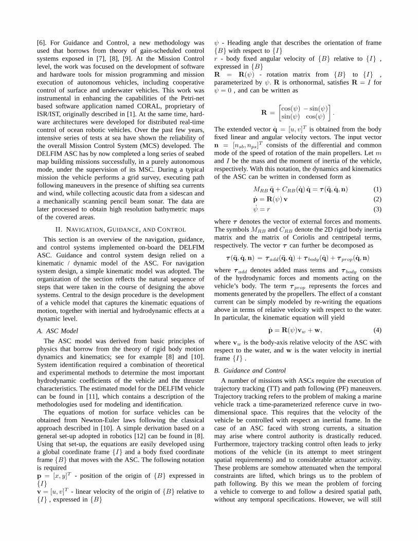
Fig. 2. Path following coordinate systems.
the parameters of linear controllers designed for a finitenumber of representative trimming trajectories. This leadsto a new class of trajectory tracking controllers that exhibittwo major advantages over classical ones: i) stability of thecombined guidance and control system is guaranteed, andii) zero steady state error is achieved about any trimmingtrajectory. Controller scheduling and implementation is doneby using so-called delta-implementation [13]. Interestinglyenough, with this strategy the structure of the final trackingcontrol law is such that the trimming values for the plantinputs and for the states variables that are not explicitlyrequired to track kinematic reference inputs are automatically”learned” during operation. The importance of this propertycan hardly be overemphasized, for it is in striking contrastwith most known methods for trajectory tracking which buildon the unrealistic assumption that all input and state variablesalong the trajectory to be followed are computed in advance.
2) Path Following: Path following is the problem ofmaking a vehicle converge to and follow a desired spatialpath while tracking a desired speed profile. The temporaland spatial goals are therefore separated. Often, it is simplyrequired that the speed of the vehicle remain constant. Inwhat follows, it is generally assumed that the path is param-eterized in terms of its length. A point on the path is thereforespecified in terms of its curvilinear abscissa, denoteds. Thesolution to the problem of path following adopted for theDELFIM ASC is rooted in the work described in [14] forwheeled robots. When extended to marine robots, the keyideas explored can be briefly explained by considering Figure2, which depicts the situation where a vehicle follows a twodimensional path denotedΓ.
A path following controller should compute i) the lengthof vectord from the vehicle’s center of mass to the closestpoint P on the path (if this distance is well defined) andii) the angle between the vehicle’s total velocity vector andthe tangent to the path atP , and reduce both to zero. Statedequivalently, the objective is to align the total velocity vectorwith xT , where the latter is tangent to the path and iseasily identified with thex− axis of so-called Serret-Frenet{T} frame at pointP (s). Clearly, xT plays the role of theflow frame of a ”virtual target vehicle” with body frame{C} that should be tracked by the flow frame of the actualvehicle. The mismatch between the two frames (as measured

by the linear distance and angle between the two) plays akey role in the definition of the error space where the pathfollowing control problem can be formulated and solved.
A solution to the problem of path following that relies ongain-scheduling control theory and on the linearization of aconveniently defined generalized error vector about trimmingpaths, akin to that previously described for trajectory track-ing, is reported in [8]. See also [7] for an application of thesame techniques to aircraft control.
C. Navigation
Navigation systems are essential to the operation of mobilerobots that perform complex missions in autonomous mode.See [15], [16], [17], [18] and the references therein fora broad view of navigation system design methodologiesin the ocean robotics area. Traditionally, navigation systemdesign is done in a stochastic setting using Kalman-Bucyfiltering theory [19]. For nonlinear systems, design solutionsare usually sought by resorting to Extended Kalman filteringtechniques.
If the sensors used in a navigation system are sampled atthe same frequency, the corresponding filter operators are lin-ear and time-invariant. This leads to a fruitful interpretationof the filters in the frequency domain. In the case of linearposition and velocity estimation, however, the characteristicsof global positioning systems such as the NAVSTAR-GPSimply that the position measurements are available at a ratethat is lower than those of the remaining sensors installed onboard. To deal with this problem a multi-rate complementaryKalman filtering design technique was developed for theDELFIM ASC. See [6] and the references therein. The ASCis equipped with the following motion sensors:
1) a NAVSTAR GPS(Global Positioning System) receiverthat computes the latitude, longitude, and altitude inthe WGS-84 datum. The GPS receiver, running ad-vanced positioning algorithms, namely the Real TimeKinematics (RTK), can achieve centimetric accuracy inthe fixed version and decimetric accuracy in the floatversion.
2) a Doppler log sonarthat provides on-board referencedmeasurementsvm
w of body-fixed relative velocity vectorvw.
3) An attitude reference that gives very accurate estimatesof yaw angleψ and respective angular velocityr.
Based on the coordinates provided by the GPS, after asuitable transformation to the local coordinate frame{I} ,the positionp = [x, y]T becomes available. The Doppler dataare simply converted from body to inertial reference frameto obtain measurements of relative velocity in{I} . Theinterrogation rates for the GPS and for the Doppler sonar are2Hz and4Hz, respectively. The following specifications forthe navigation system were set as guidelines for the designof a multi-rate complementary filter:
1) Obtain good estimates of the vehicle position andvelocity;
2) Achieve a settling time of240 s on the estimate of thewater current velocity.
3) Achieve a settling time of6s on the position estimate.
The design model for the complementary navigation filteris easily obtained from the kinematic equations of the ASC,leading to two sets of decoupled equations that correspondto the two linear coordinatesx, andy. For each coordinate,the design model is given by
x(k + 1) = A(k)x(k) + Bu(k)u(k)z(k) = Cz(k)x(k)y(k) = Cy(k)x(k),
(5)
with x =[x1 x2
]T, wherex1 represents linear coordinate
x or y andx2 is an appended state aimed at estimating thecorresponding component of the water velocity in{I} . Inthe model, the inputu = R(ψ)vm
w is the measured valueof relative velocity of the vehicle expressed in{I} , z is anartificial observation vector that shapes the performance ofthe filter, andy is the vector of periodic observations. In thepresent application,
A(k) =[
1 h0 1
], Bu(k) =
[h0
],
Cy(k) ={ [
1, 0]
if k MOD 2 = 0[0, 0
]if k MOD 2 = 1 ,
and Cz(k) =[1 0
]T. The periodic nature of the matrix
Cy(k) is obvious. For DELFIM, the observer feedbackgains were obtained by solving a periodicH2 problem usingLinear Matrix Inequalities (LMIs). The reader is referredto [6] for complete details on the design methodology thatextends classical concepts of complementary filtering to aperiodic setting.
III. M ISSION CONTROL SYSTEM
The previous sections described some of the techniquesused for ASC control and navigation. In what follows wedescribe briefly how to transition from theory to practice.To do this, two key ingredients are needed: i) a distributedcomputer architecture, and ii) a software architecture for sys-tem implementation and human-machine interfacing. Whenimplemented in a fully operational vehicle (equipped withthe systems for navigation, guidance, and control, togetherwith the remaining enabling systems for energy and scien-tific payload management, actuator control, and communi-cations), the latter is often referred to as Mission ControlSystem. For our purposes, a Mission Control System issimply viewed as a tool allowing a scientific end-user notnecessarily familiarized with the details of marine roboticsto program, execute, and follow the progress of single ormultiple vehicles at sea. With the set-up adopted at IST/ISR,mission design and mission execution are done seamlesslyby resorting to simple, intuitive human/machine interfaces.Missions are simply designed in an interactive manner byclicking and dragging over the desired target area maps andselecting items out of menus that contain a list of possiblevehicle actions. See Figure 3, which is a printout of agraphical interface for mission design. Notice the presence ofa mission map (map of the area to be covered) with obstaclesto be avoided, together with a menu of the vehicles availableto execute the mission that is being designed. Available to
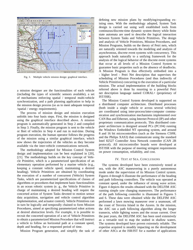
Fig. 3. Multiple vehicle mission design: graphical interface.
a mission designer are the functionalities of each vehicle(including the types of scientific sensors available), a setof mechanisms enforcing spatial / temporal multi-vehiclesynchronization, and a path planning application to help inthe mission design process (so as to meet adequate temporal/spatial / energy requirements).
The process of mission design and mission executionunfolds into four basis steps. First, the mission is designedusing the graphical interface described above. A missionprogram is automatically generated in Step 2 and compiledin Step 3. Finally, the mission program is sent to the vehicleor fleet of vehicles in Step 4 and run in real-time. Duringprogram execution, the human operator follows the progressof the mission using a similar graphical interface, whichnow shows the trajectories of the vehicles as they becomeavailable via the inter-vehicle communications network.
The methodology adopted for Mission Control Systemdesign and implementation can be best explained in [20],[21]. The methodology builds on the key concept of Vehi-cle Primitive, which is a parameterized specification of anelementary operation performed by a marine vehicle (e.g.,keeping a constant vehicle speed, maintaining a desiredheading). Vehicle Primitives are obtained by coordinatingthe execution of a number of concurrent (Vehicle) SystemTasks, which are parameterized specifications of classes ofalgorithms or procedures that implement basic functionalitiesin an ocean robotic system (e. g., the Vehicle Primitive incharge of maintaining a desired heading will require theconcerted action of System Tasks devoted to motion sensordata acquisition, navigation and vehicle control algorithmimplementation, and actuator control). Vehicle Primitives canin turn be logically and temporally chained to form MissionProcedures, aimed at specifying parameterized robot actionsat desired abstraction levels. For example, it is possible torecruit the concerted operation of a set of Vehicle Primitivesto obtain a parameterized Mission Procedure that will instructa vehicle to follow an horizontal path at a constant speed,depth and heading, for a requested period of time.
Mission Program generation, and simplify the task of
defining new mission plans by modifying/expanding ex-isting ones. With the methodology adopted, System Taskdesign is carried out using well established tools fromcontinuous/discrete-time dynamic system theory while finitestate automata are used to describe the logical interactionbetween System Tasks and Vehicle Primitives. The designand analysis of Vehicle Primitives, Mission Procedures, andMission Programs, builds on the theory of Petri nets, whichare naturally oriented towards the modeling and analysis ofasynchronous, discrete event systems with concurrency. Thisapproach leads naturally to a unifying framework for theanalysis of the logical behavior of the discrete event systemsthat occur at all levels of a Mission Control System toguarantee basic properties such as the absence of deadlocks.A Mission Program is thus effectively embodied into a- higher level - Petri Net description that supervises thescheduling of Mission Procedures (and thus indirectly ofVehicle Primitives) concurring to the execution of a particularmission. The actual implementation of the building blocksreferred above is done by resorting to a powerful Petrinet description language named CORAL+ (proprietary ofIST/ISR).
The Mission Control System developed is supported ona distributed computer architecture. Distributed processes(both inside a single vehicle or across several vehicles)are coordinated using inter-process/inter-computer commu-nication and synchronization mechanisms implemented overCAN Bus and Ethernet, using Internet Protocol (IP) and otherproprietary communication protocols. This distributed com-puter architecture is designed around PCs (PC104) runningthe Windows Embedded NT operating system, and around8 and 16 bit microcontrollers (such as the Siemens C509Land the Philips XAS3) that communicate using the standardIntel 82527 Controller Area Network controller (CAN 2Bprotocol). All microcontroller boards were developed atIST/ISR with the purpose of meeting stringent requirementson power consumption, reliability, and cost.
IV. T EST AT SEA. CONCLUSIONS
The systems developed have been extensively tested atsea, with the ASC maneuvering in a purely autonomousmode under the supervision of its Mission Control system.Figures 4 through 6 illustrate the performance of the headingand path following controllers. The vehicle was operated atconstant speed, under the influence of strong wave action.Figure 4 depicts the results obtained with the DELFIM ASCrunning simple yaw changing maneuvers. The performanceof the path following controller is illustrated in Figures 5and 6. These data were obtained while the DELFIM ASCperformed a lawn mowing maneuver over a seamount, offthe coast of Terceira Island in the Azores. In the mission,the ASC ran a path following algorithm along the longertransects, while fighting waves and the ocean current. Overthe past years, the DELFIM ASC has been used extensivelyas a versatile tool to map the seabed in shallow waters.The systems developed have proven extremely reliable. Theexpertise acquired is steadily impacting on the developmentof other ASCs at the ISR/IST for a number of applications

Fig. 4. Yaw command and vehicle response.
Fig. 5. Reference and actual vehicle paths.
that range from oceanographic surveys to the inspection ofrubblemound breakwaters.
REFERENCES
[1] A. Pascoal, P. Oliveira, C. Silvestre, L. Sebastio, M. Rufino, V. Bar-roso, J. Gomes, G. Ayela, P. Coince, M. Cardew, A. Ryan, H. Braith-waite, N. Cardew, J. Trepte, N. Seube, J. Champeau, P. Dhaussy,V. Sauce, R. Moiti, R. Santos, F. Cardigos, M. Brussieux, andP. Dando, “Advanced system integration for managing the coordinatedoperation of robotic ocean vehicles,” inProc. EurOCEAN 2000,Hamburg, Germany, Aug. 2000.
[2] J. Manley and T. Vaneck, “High fidelity hydrographic surveys usingan autonomous surface craft,” inOceans Community Conference ’98MTS Conference, Baltimore, Maryland, USA, Nov. 1998.
[3] J. Manley, A. Marsh, W. Cornforth, and C. Wiseman, “Evolution ofthe autonomous surface craft autocat,” inOceans 2000 MTS/IEEEConference, Providence, Rhode Island, USA, Nov. 2000.
[4] J. Manley, J. Curran, B. Lockyer, J. Morash, and C. Chryssostomidis,“Applying auv lessons and technologies to autonomous surface craftdevelopment,” in Oceans 2001 MTS/IEEE Conference, Honolulu,Hawaii, Nov. 2001.
[5] A. Pascoal, I. Kaminer, and P. Oliveira, “Navigation system designusing time-varying complementary filters,”IEEE Trans. Aerospace andElectronic Systems, Vol. 36, N0.4, 2000.
[6] P. Oliveira, “Periodic and nonlinear estimators with applications tothe navigation of ocean vehicles,” Ph.D. dissertation, Department ofElectrical Engineering, Instituto Superior Tcnico, Lisbon, Portugal,2002.
Fig. 6. Path following error.
[7] I. Kaminer, A. Pascoal, E. Hallberg, and C. Silvestre, “Trajectorytracking for autonomous vehicles:an integrated approach to guidanceand control,” AIAA Journal of Guidance, Control, and Dynamics,21(1): 29-38, 1998.
[8] C. Silvestre, “Multi-objective optimization theory with applications tothe integrated design of controllers / plants for autonomous vehicles,”Ph.D. dissertation, Department of Electrical Engineering, InstitutoSuperior Tcnico, Lisbon, Portugal, 2000.
[9] C. Silvestre, A. Pascoal, and I. Kaminer, “On the design of gain-scheduled trajectory tracking controllers,”International Journal ofRobust and Nonlinear Control, Vol.12, pp.797-839, 2002.
[10] M. Abkowitz, “Lectures on ship hydrodynamics - steering and ma-neuverability,” Technical University of Denmark, Hydrodynamics De-partment,Lyngby, Denmark, Tech. Rep., May 1964, technical ReportHy-5.
[11] M. Prado, “Modeling and control of an autonomous oceanographic ve-hicle,” Master’s thesis, Department of Electrical Engineering, InstitutoSuperior Tcnico, Lisbon, Portugal, 2002.
[12] J. J. Craig,Introduction to Robotics and Control: Mechanics andControl, 2nd ed. Massachusetts, USA: Addison-Wesley PublishingCompany, 1989.
[13] I. Kaminer, A. Pascoal, P. Khargonekar, and E. Coleman, “A VelocityAlgorithm for the Implementation of Gain-Scheduled Controllers,”Automatica, vol. 31, no. 8, pp. 1185–1191, 1995.
[14] C. Samson, “Path Following and Time-Varying Feedback Stabilizationof a Wheeled Mobile Robot,” inInternational Conference ICARCV’92,no. RO-13.1, Singapore, 1992.
[15] D. Fryxell, P. Oliveira, A. Pascoal, and C. Silvestre, “An integratedapproach to the design and analysis of navigation, guidance and controlsystems for auvs,” 1994.
[16] D. Jourdan, “Doppler sonar navigation error propagation and correc-tion,” Journal of the Institute of Navigation, Vol. 32, No. 1, pp. 29-56,1985.
[17] J. Stambaugh and R. Thibault, “Navigation requirements for au-tonomous underwater vehicles,”Journal of the Institute of Navigation,Vol. 39, No. 1, pp. 79-92,, 1992.
[18] D. Jourdan, “A novel method for extending gps to underwater vehi-cles,” Journal of the Institute of Navigation, Vol. 38, No. 3, pp. 263-271, 1991.
[19] R. Brown and P. Hwang,Introduction to Random Signals and AppliedKalman Filtering, Second Edition, John Wiley and Sons, New York,1992.
[20] P. Oliveira, A. Pascoal, V. Silva, and C. Silvestre, “Mission controlof the marius autonomous underwater vehicle: system design, imple-mentation, and sea trials,”International Journal of Systems Science,Special Issue on Underwater Robotics, Vol. 29, N0. 10, pp. 1065–1080,1998.
[21] R. Oliveira,Supervision and mission control of autonomous vehicles,MSc. Thesis, Department of Electrical Engineering, Instituto SuperiorTecnico, Lisbon, Portugal, 2003.