Embed Size (px)
Citation preview

Minnesota Power Systems Conference
St. Paul, MN
November 7-9, 2017
Delayed Current Zero Crossing
Phenomena During Switching of
Shunt-Compensated Lines
David K Olson Pratap G Mysore
Paul Nyombi Pratap Consulting Services
Xcel Energy

Acknowledgement
2
•American Transmission Company (ATC) study
group for bringing up DCZ issues during the line
design studies on one of the CAPX lines.
•This prompted three utilities associated with CAPX
to determine the impact of shunt reactors on their
lines and to determine mitigation methods.

Transmission Line Representation
3
• Long Transmission lines can be represented as several series connected
modules made up of series resistance, Series Inductance and Shunt
capacitance.
• Lines are also represented with Lumped parameters where the line
capacitances are split between two ends.
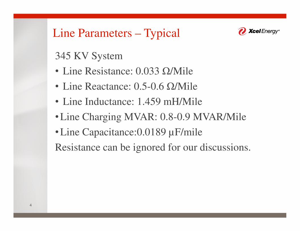
Line Parameters – Typical
4
345 KV System
• Line Resistance: 0.033 Ω/Mile
• Line Reactance: 0.5-0.6 Ω/Mile
• Line Inductance: 1.459 mH/Mile
•Line Charging MVAR: 0.8-0.9 MVAR/Mile
•Line Capacitance:0.0189 µF/mile
Resistance can be ignored for our discussions.

Transmission Line Behavior
5
•During Light load or no load conditions,
Transmission line has the same effect as
capacitance connected to the system.
•System voltage increases with the connection of
open ended transmission Lines.
•Capacitance of the line is distributed over the entire
length. Remote end voltage increases with increase
in length – Also Known as Ferranti Effect

Shunt Reactor Application
6
•To Keep System Voltage below allowable
maximum value
•System voltage needs to be within the allowable
range to prevent connected Equipment failures.
- IEEE 1312- 1993 (R2004) “IEEE Standard Preferred
Voltage Ratings for Alternating-Current Electrical Systems and
Equipment Operating at Voltages Above 230 kV Nominal”
• Installed on
–Tertiaries of transmission Transformers
– On Transmission Lines –Either at both Ends or at
only one end.
–Middle of the line

Shunt Compensated Lines
7
•Transmission Lines with shunt reactors connected.
• Total shunt reactor MVAR_R = Sum of all shunt
reactors connected on the line.
•Degree of Compensation, M = _
_
Where, MVAR_C is the Line Charging MVAR
Degree of Compensation is determined by planning
studies- Can exceed 100%

Effect of Shunt Reactors
8
• Decreases the voltage by compensating for the capacitive charging
currents.
• Reactor current, IL lags voltage by 900
• Capacitor (line charging) current, IC leads voltage by 900
• Decreases the current through the breaker current (|IC |- |IL |)
(f ile Paper1.pl4; x-v ar t) factors:
offsets:
1
0
v :I_L1 1.00E-03
0
c:I_C2 - 1
0
c:I_L1 -I_L2 1
0
c:XX0002-I_L1 1
0
0 10 20 30 40 50 60 70*10 -3
-300
-200
-100
0
100
200
300
Steady State current and Voltage phase relationship

Line Currents During Energization
9
• Voltage waveform: V Sin (ωt +φ) where φ is the
delay angle of switching on the voltage waveform
from voltage zero.
•Charging (Capacitive) Current: I Sin(ωt+φ+90)
•Reactor Current: MI [Sin (ωt+φ-90)+ Cosφ e-t/τ]
(f ile Paper1.pl4; x-v ar t) v :XX0006
0.00 0.02 0.04 0.06 0.08 0.10-300
-200
-100
0
100
200
300
*103
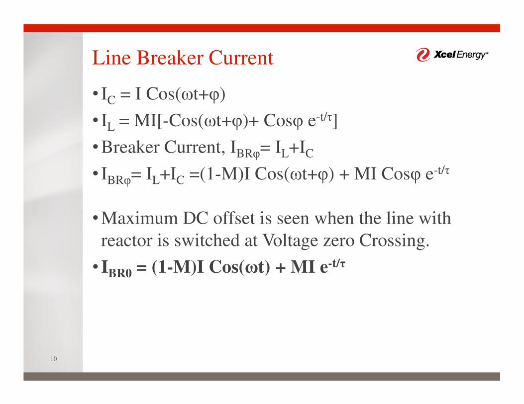
Line Breaker Current
10
• IC = I Cos(ωt+φ)
• IL = MI[-Cos(ωt+φ)+ Cosφ e-t/τ]
•Breaker Current, IBRφ= IL+IC
• IBRφ= IL+IC =(1-M)I Cos(ωt+φ) + MI Cosφ e-t/τ
•Maximum DC offset is seen when the line with
reactor is switched at Voltage zero Crossing.
• IBR0 = (1-M)I Cos(ωt) + MI e-t/τ

Line Breaker Current Components
11
•AC sinusoidal wave has a peak value of (1-M)I
•DC component is exponentially decaying with time
constant of τ sec.
• X/R of oil filled reactors are in the range of 600-
750; τ can be as high as 2 seconds (~=750/377).
•DC component will decay to less than 2% of the
initial value after 4τ time.

Line Breaker Delayed Current Zero
12
• If AC component Peak (1-M)I is greater than DC
component MI, AC waveform will always cross
current zero axis or else, Current zero occurs after
a delay.
Delayed
Current
Zero
-0.5
0
0.5
1
1.5
2
2.5
3
3.5 Delayed Current Zero (DCZ)
DC Component
Breaker Current

Criterion to Prevent DCZ during
Normal Switching
13
•Boundary Condition: (1-M)I = MI;
•M = 0.5;
•Under normal switching, the degree of
compensation, M cannot exceed 50% to prevent
Delayed Current Zero on Breaker Current.

Time to first Current Zero
14
• If the Degree of compensation is greater than 50%,
the AC waveform will cross current zero line when
the peak equals or exceeds the decayed DC
component
• (1-M) = M * e-t/τ
•Solving for t , tSeconds τln
;
0
0.2
0.4
0.6
0.8
1
1.2
0 2 4 6 8 10
Deg
ree
of
Co
mp
ensa
tio
n
Time for first current zero
Degree of Compensation VS Time to
first Current Zero (τ =2 sec)
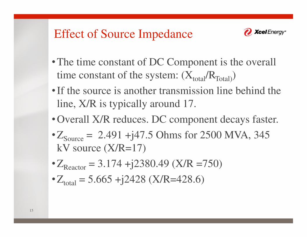
Effect of Source Impedance
15
•The time constant of DC Component is the overall
time constant of the system: (Xtotal/RTotal))
• If the source is another transmission line behind the
line, X/R is typically around 17.
•Overall X/R reduces. DC component decays faster.
•ZSource = 2.491 +j47.5 Ohms for 2500 MVA, 345
kV source (X/R=17)
•ZReactor = 3.174 +j2380.49 (X/R =750)
•Ztotal = 5.665 +j2428 (X/R=428.6)

Energizing Faulted Line
16
•Fault Location: at the shunt Reactor
•Voltage Shift on un-faulted phase is the maximum
at the fault location and is maximum for double
line to Ground Fault
•Voltage of B-Phase (PU) for A-G fault
• | VB| = |e-j240 -
| ; K=
•B-C-G fault, VA (PU) =
•For K=2.8, A-Phase voltage increases to 1.273 PU
for B-C-G fault
•B-phase voltage increases to 1.23

M Limit - Effect on DCZ due to Faults
17
•Voltage rise on un-faulted phase of the shunt
reactor results in higher DC component due to
Voltage zero switching and also due to voltage rise.
•Capacitive current doesn’t increase in the same
proportion due to distributed Capacitance of the
line.
• Is affected by inter-phase capacitance
•Transient studies are needed to determine the
reduction in M from 50% to prevent DCZ
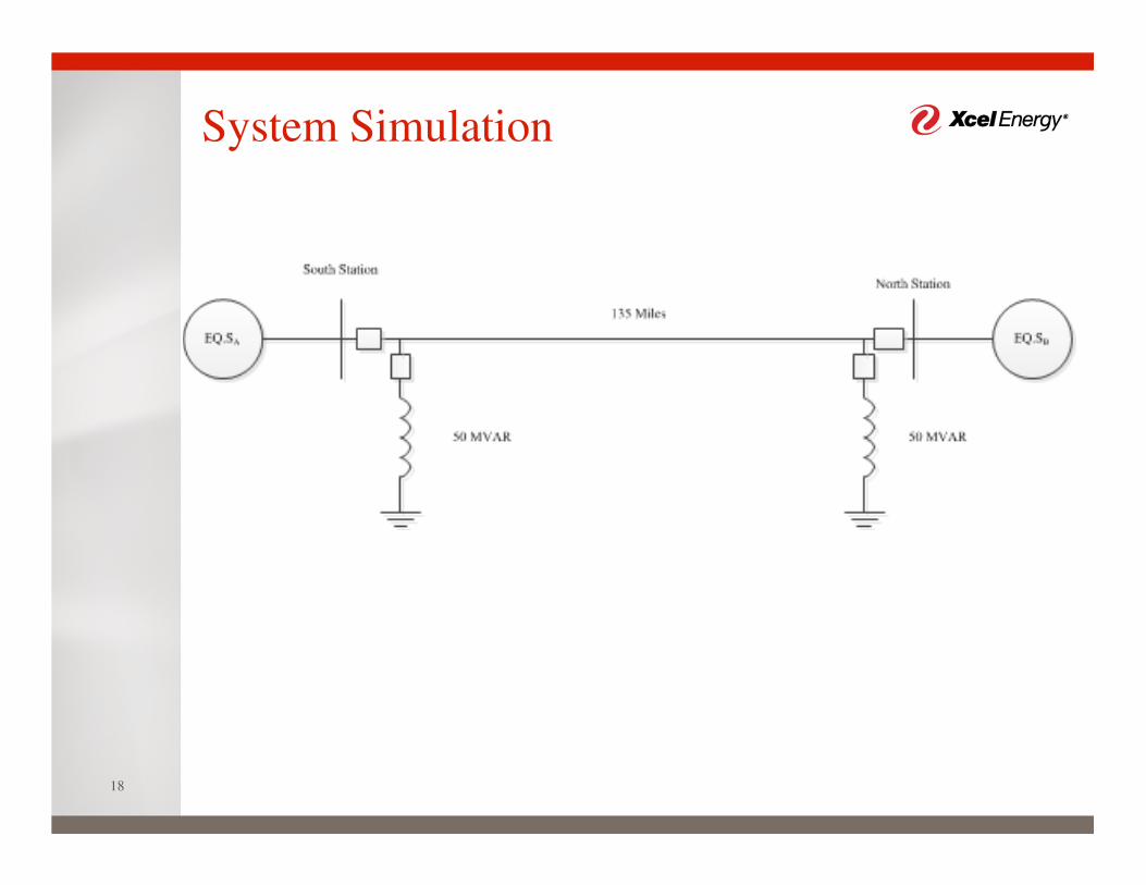
System Simulation
18
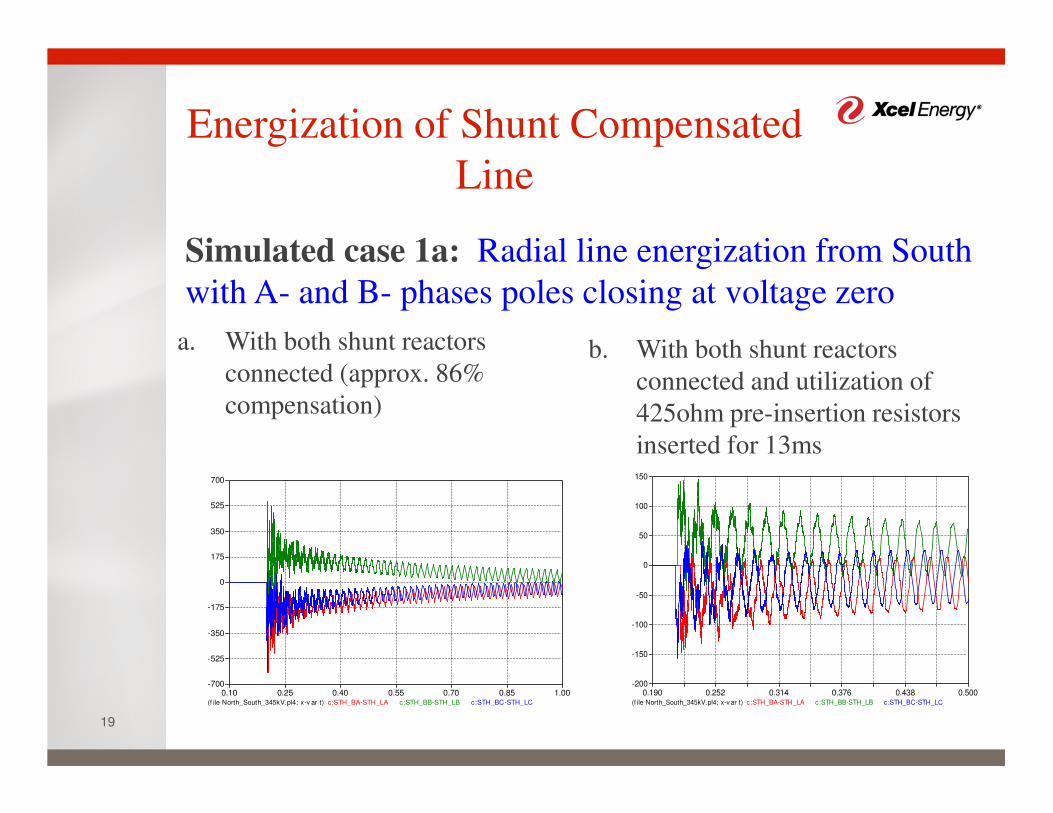
Energization of Shunt Compensated
Line
19
Simulated case 1a: Radial line energization from South
with A- and B- phases poles closing at voltage zero
a. With both shunt reactors
connected (approx. 86%
compensation)
b. With both shunt reactors
connected and utilization of
425ohm pre-insertion resistors
inserted for 13ms
(f ile North_South_345kV.pl4; x-v ar t) c:STH_BA-STH_LA c:STH_BB-STH_LB c:STH_BC-STH_LC
0.10 0.25 0.40 0.55 0.70 0.85 1.00-700
-525
-350
-175
0
175
350
525
700
(f ile North_South_345kV.pl4; x-v ar t) c:STH_BA-STH_LA c:STH_BB-STH_LB c:STH_BC-STH_LC
0.190 0.252 0.314 0.376 0.438 0.500-200
-150
-100
-50
0
50
100
150

Energization of Shunt Compensated
Line
20
Simulated case 1b: Radial line energization from South
with A- and B- poles closing at voltage zero
a. With only North line-end shunt
reactor connected (approx. 43%
compensation)
b. Energizing the transmission
line into a close-in BC-Ground
fault with only one reactor
connected. A-Phase current is
shown below
(f ile North_South_345kV.pl4; x-v ar t) c:STH_BA-STH_LA c:STH_BB-STH_LB c:STH_BC-STH_LC
0.15 0.20 0.25 0.30 0.35 0.40 0.45 0.50-600
-400
-200
0
200
400
600
(f ile North_South_345kV.pl4; x-v ar t) c:STH_BA-STH_LA
0.15 0.24 0.33 0.42 0.51 0.60-600
-450
-300
-150
0
150
300

Energization of Shunt Compensated
Line
21
Observations:
Energization of the line with only one reactor connected
eliminates DCZ – 43% shunt compensation
DCZ may also be minimized by using pre-insertion
resistors and/or increasing pre-insertion time
Several faults may need to be studied as their impact on
DCZ depends on other factors like system parameters and
line configuration. 43% compensation was found to be
adequate in this case for minimizing DCZ for all switching
scenarios.

Switching of Shunt Reactor on an
energized line
22
a. Switching South line-end shunt
reactor during limited/no
loading on the line. South line
end breaker currents are shown
below:
b. Switching of the shunt reactor
with at least 46MW flowing
from South to North
substation. DCZ on South
line-end currents is
eliminated.
(f ile North_South_345kV.pl4; x-v ar t) c:STH_BA-STH_LA c:STH_BB-STH_LB c:STH_BC-STH_LC
0.3 0.4 0.5 0.6 0.7 0.8-120
-80
-40
0
40
80
120
(f ile North_South_345kV.pl4; x-v ar t) c:STH_BA-STH_LA c:STH_BB-STH_LB c:STH_BC-STH_LC
0.38 0.40 0.42 0.44 0.46 0.48 0.50 0.52-200
-150
-100
-50
0
50
100
150
200

Switching of Shunt Reactor on an
energized line
23
Observations:
Switching of shunt reactor at voltage zero crossings creates
DC offsets at line-end breakers, with the strongest source
experiencing the greatest offset.
Line breakers experience DCZ if the offset is greater than
the capacitance from the reactor up to the breaker location.
A minimum of 46MW, power flow from South to North, is
found to be adequate in mitigating the delayed current zeros
when energizing the second shunt reactor

Switching of line/shunt reactor for
transmission line fault events
24
Simulated case 3a: South line-end A-Phase reactor current
following a close-in A-G fault on transmission line
Under this study:
A-Phase to ground fault is
considered to occur at A-Phase
voltage zero crossing
Both reactors are connected
with the line closed through
Shunt reactor current takes
several cycles to decay to zero;
X/R ~ 1.68s
(f ile North_South_345kV.pl4; x-v ar t) c:STH_LA-STH_RA
0 2 4 6 8 10-120
-80
-40
0
40
80
120

Transmission line de-energization
under no fault conditions
25
Simulated case 3b: South line-end B-Phase line voltage
following line de-energization with both reactors connected
Trapped energy in the shunt
capacitance and shunt reactors
creates high frequency transients
that may take several seconds to
decay
A- and C- Phases also do
experience voltage transients.
Only B-Phase is shown for
clarity.
(f ile North_South_345kV.pl4; x-v ar t) v :STH_LB
0 2 4 6 8 10-300
-200
-100
0
100
200
300
400
*103

Switching of line/shunt reactor for
transmission line fault events
26
Observations:
Shunt reactors should not be tripped for faults on
transmission line.
Disabling high-speed reclosing is recommended especially
for lines that have more than 50% compensation. Adequate
time may be required before safely reducing the shunt
compensation for re-energization.

Delayed Current Zero Mitigation
Methods
27
1. Use of pre-insertion resistors on line breakers
Limitations:
Breaker manufacturers do typically guarantee only 8-12ms
of pre-insertion time. Pre-insertion time of at least 13ms
was required in our case study during normal energization.
The time duration was not enough to eliminate DCZ during
faulted line energization.
Depending on the breaker closing mechanism, increasing
pre-insertion resistor size created new transients when the
main contact by-passes the pre-insertion resistor

Delayed Current Zero Mitigation
Methods
28
2. Limit degree of line compensation during line
energization
Limitations:
Reduced line compensation increases remote end line
voltages. Remote end line connected equipment must be
rated adequately – Surge Arrestors, CCVTs, etc
Delayed Current Zero Mitigation
Methods
29
3. Utilization of controlled closing on shunt reactor
breakers
Limitations:
Implementation of this may be challenging on existing
shunt reactor breakers as this may require breaker upgrade
Delayed Current Zero Mitigation
Methods
30
4. Consider moving reactors (or some of them) from
transmission line to substation buses
Limitations:
Implementation of this may be challenging for existing
substations

Tripping and reclosing considerations for
shunt compensated lines
31
Radial energization of a transmission line with less 50%
shunt compensation is recommended.
Disabling high-speed reclosing is recommended on lines
with more than 50% shunt compensation.
Tripping and reclosing considerations for
shunt compensated lines
32
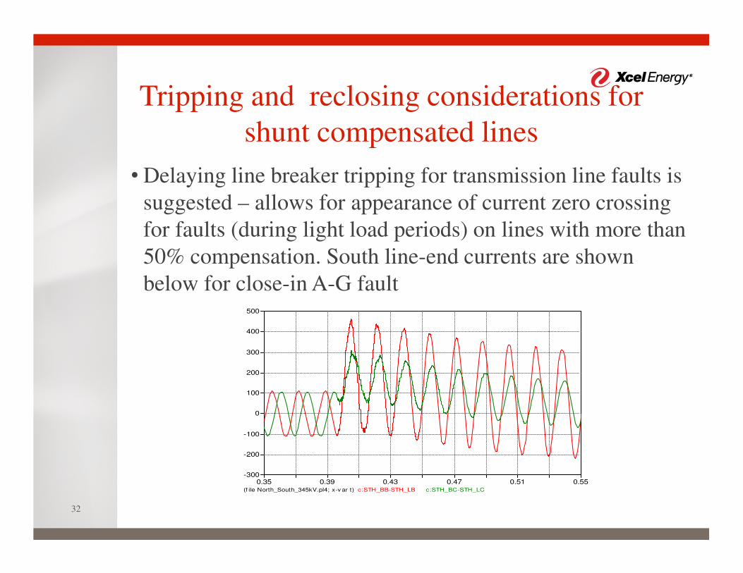
• Delaying line breaker tripping for transmission line faults is
suggested – allows for appearance of current zero crossing
for faults (during light load periods) on lines with more than
50% compensation. South line-end currents are shown
below for close-in A-G fault
(f ile North_South_345kV.pl4; x-v ar t) c:STH_BB-STH_LB c:STH_BC-STH_LC
0.35 0.39 0.43 0.47 0.51 0.55-300
-200
-100
0
100
200
300
400
500
Conclusions
33
a. On line energization to prevent DCZ:
If shunt reactor(s) on the line is not required to limit
open end voltage to acceptable level, energize the line
without shunt Reactors.
Keep Shunt Compensation below 50% during line
energization.
Energize the line through breakers equipped with pre-
insertion resistors that provide enough damping to
produce current zeros within breaker interrupting time.
This is dependent on the resistor value and duration of
insertion. It may not work under all the cases if the
degree of compensation is close to 100%.

Conclusions
34
b. On Shunt reactor energization onto energized lines,
to prevent DCZ:
Switch shunt reactors less than 50% of the total
charging current.
Switch shunt reactor at voltage maximum point on the
wave.
Switch shunt reactors if their inductive MVAR is not
greater than the minimum load on the line, in MW.
Conclusions
35
c. Tripping for line faults:
Trip only the line breakers and not shunt reactors.
Shunt reactors need to be tripped only after several
seconds delay to allow full decay of reactor current on
the faulted phase.
Total interrupting time of faults on lines with shunt
compensation greater than 50% may need to be at least
few cycles to allow presence of current zeros on healthy
phase(s) during faults. This is dependent on the zero
sequence currents flowing on the healthy phases or the
minimum load on the healthy phases.
Conclusions
36
d. Tripping for shunt reactor faults:
Trip the shunt reactors only if they are equipped with
breakers.
Conclusions
37
e. Reclosing on Lines:
Instantaneous reclose is disabled on lines where shunt
reactor switching is required to reduce the degree of
compensation.
Time delay reclose is enabled after the reactor is
switched out.
Synch-check reclosing at the other end after energizing
the line may generate offsets on the currents. DC offset
is dependent on the load picked up after restoration.

Questions
38