Embed Size (px)
Citation preview
Delamination of Z-pinned carbon fibre reinforced laminates
Denis D.R. Cartié, Manos Troulis and Ivana K. Partridge
Advanced Materials Department, Cranfield University, Cranfield, Bedford, MK43 0AL,
Abstract
The paper outlines the current status of mechanical testing, identification of failure mechanisms
and data analysis related to delamination cracking in high performance laminates made via the
prepreg/autoclave route, strengthened in the through-thickness direction by Z-pinning. The
applied loading cases under consideration are limited to Mode I and Mode II. Sample
preparation, test methodologies and applicability of data reduction schemes are considered, with
data obtained from within the range of aerospace and Formula 1 grades of carbon fibre / epoxy
composites. Micromechanisms of failure in the three dimensional tests specimens are shown to
be dependent on the architecture of the fibre reinforcement (i.e. unidirectional versus woven
fabric prepregs), particularly in the case of Mode II loading.
Keywords
Z-Fiber ® A. Polymer matrix composites (PMCs) C. Delamination
1 INTRODUCTION
The increasing use of polymer matrix composite materials in newly designed aircraft and motor
vehicles bears witness to the increasing confidence in their use. Examples of design commitment
to the use of composites in load-bearing aircraft structures are the keel beam of the Airbus A340-

600, which resulted in the required weight saving [1], and the centre wingbox of the new A380.
The new Boeing 7E7 is intended to contain a considerably higher proportion of composite in its
structure than has been used on any equivalent aircraft so far. Damage tolerant design of such
large structures must involve an understanding of crack growth management to achieve the
desired safe life and specific performance of the structure, at an acceptable cost.
In the Formula 1 industry, stiffness, strength and weight distribution are critical to the
performance of the racing car. Composites are the material of choice for their high specific
strength and stiffness but also for the short lead times in the manufacture of small numbers of
novel and relatively complex aerodynamic shapes. As in the aircraft case, the limiting factors on
most structural parts in a F1 racing car are rarely the loading conditions experienced during their
“standard” life, but more extreme loading conditions imposed by the FIA (Federation
International d’Automobile). There are stringent and increasingly demanding regulatory
conditions, to make the cars safer for the drivers and for the spectators. Any damage created
during the race must be contained and the car must be able to finish the race [2].
All composite structures contain cracks, their existence being only a matter of scale. The
management of these cracks is thus a key issue. Any modification of the composite structures
which provides reliable and reproducible means of stopping delamination cracks would be
expected to be of interest. At the present time several 3D technologies are under investigation in
this context, namely: - stitching, tufting, 3D weaving and Z-Fiber® reinforcement [3]. This
paper is concerned solely with Z-Fiber® reinforcement., thereafter referred to as Z-pinning [4].
For the measurements reported in this paper, two basic types of test specimens were prepared:
double cantilever beam specimens of dimensions within the range of the currently specified
delamination testing procedures and short beams of composite for the newly designed ‘Z-shear’

test (see section 3.4). In both cases, blocks of orthogonally inserted Z-pins are located in selected
positions along the laminate beams. The 0.28mm and 0.51 mm diameter Z-pins used in this work
have been manufactured in the form of a continuous rod-stock, by a pultrusion batch process
from 1k or 3k carbon fibre tows and cured to contain about 30% by volume of bismaleimide
(BMI) resin. The high glass transition temperature of the fully cured BMI resin ensures that the
Z-pins remain rigid throughout all subsequent manufacturing steps. Practical details of composite
sample preparation are given elsewhere [4,5], but the essence of the procedure is as follows:
- Cured carbon fibre/ BMI resin Z-pins are provided by the manufacturer in the form of
square array strips of Z-pins inserted into a double layer foam (Fig.1).
- The strip of Z-pins is placed in a selected location, on top of an uncured laminate and
pins are inserted with the aid of an ultrasonic gun [6]. The high frequency/low amplitude
oscillations of the ultrasound gun cause enough energy to be absorbed by the uncured
prepreg to allow the resin to heat up and soften. Direct pressure application onto the
insertion gun makes the orthogonal Z-pins slip easily in between the reinforcement fibres
of the laminate, causing minimal damage.
- The collapsed foam and any excess length of Z-pins left on the surface of the laminate are
sheared off by a metal tool and the laminate is bagged and cured in the normal fashion. A
good surface finish, a good bond to and a seal around the inserted Z-pins are achieved as
the resin flows during the cure process.
There is a range of preforms available, each characterised by the diameter of the Z-pins, the areal
density of Z-pinning and the initial length of Z-pins. This paper reports data from a range of
prepreg raw materials and samples reinforced to varying degrees by the Z-pinning process. All
the prepregs used in this investigation were provided by Hexcel Composites (UK), located in

Duxford nr. Cambridge; the Z-pin preforms were provided by Aztex Inc., located nr. Boston,
MA, USA.
The following code is adopted for sample identification:
- CF type/Resin type/Areal density of Z-pinning /Z-pin diameter
For the purposes of this paper, the data presentation is subdivided by the dominant applied mode
of loading on the sample, namely Mode I and Mode II.
2 RESPONSE TO MODE I LOADING
The Mode I delamination testing of composite laminated beams is facilitated by the existence of a
standard test protocol and data analysis, ISO15024. Our testing was carried out at a constant
crosshead speed of 1 mm/min. Double cantilever beam (DCB) specimens were made, containing
a block of Z-pins (at least 25mm in length) located at 5 mm beyond the end of the crack starter
film. Thus the crack initiation values obtained are identical to those obtained from control
samples of the same composite. However, thereafter, the way in which the crack propagates is
affected greatly by the presence of the Z-pins, as indicated in Fig.2. In the case of the
unidirectional IMS/924 beams the nature of the crack propagation is changed from a stable and
steady nature in the control samples to ‘stick – slip’ behaviour in the Z-pinned samples. The
crack gets stopped shortly after passing through a row of Z-pins, in a manner analogous to the
classical ‘crack-pinning’ in particulate composites. The Z-pins then act in the wake of the
delamination front, bridging the crack as they gradually debond and pull-out from the beam arms,
as the crack opening displacement increases. This is the dominant mechanism of energy
absorption associated with the presence of the Z-pins in these specimens. It should be noted that
the surface area of frictional contact, per length of crack, is greater in the case of 2%/0.28 mm
specimens than in the 2%/0.51 specimens, which explains the significant difference between the

delamination responses of these two samples. Once the crack has passed beyond the Z-pinned
area (corresponding to crack lengths between 75 and 80 mm, depending on the exact geometry of
each specimen), the resistance to crack propagation begins to fall again as the crack bridging
force created by friction between the Z-pins and the beam arms reduces in proportion to the
reducing surface area of contact.
The micrograph in Fig.3 shows three individual Z-pins, one ahead of the crack the crack tip and
two bridging a growing delamination in a Mode I specimen. The traction force exerted by a
single Z-pin has been determined experimentally [4,5,7] and used in the development of FE
models for the case of Mode I delamination in Z-pinned laminates [4,5,8,9]. The quality of the
agreement between the experimental data and a simple 2D FE model of this problem, shown in
Fig.2, is very good because the ‘a-posteriori’ model takes into account all geometrical features of
the individual specimen. Such ‘local’ FE model is intended to be used in a predictive sense for
more complex structures, where the geometry of localised Z-pinning reinforcement is fully
defined. Detailed discussion of the FEA methods and results is beyond the scope of the present
paper, and will be published in a future communication.
It is important to emphasise that the fracture toughness value in this context is not a material
property, rather a specific ‘material – structure’ attribute. Analytical models describing the crack
bridging actions of Z-pins in both Mode I and mixed Mode I / Mode II are in an advanced state of
development [10-12]. Completed models of this type and/or traction laws determined by
measurements on representative single pin specimens are needed for more ‘zonal – global’
modelling of the structural response of any Z-pin containing elements.
3 RESPONSE TO MODE II LOADING.

No internationally agreed standard is currently available for this test, although the sample
dimensions and the basics of the test follow those used in the standard Mode I tests. A particular
problem associated with the measurement is the determination of the correct position of the crack
tip [13]. The extent to which the presence of the through-the-thickness reinforcement may
invalidate any of the particular approaches to the data reduction from this test is unknown. The
Mode II toughness values quoted thereafter are termed ‘apparent’ toughness, to reflect the
uncertainty in the validity of the determination.
3.1 3 point ENF test results
The most obvious effect of the presence of Z-pins in a pre-cracked laminate beam subjected to
forward shear loading (Mode II) is shown by the load-displacement curves in Fig.4. In the
commonly used 3point Edge Notched Fracture test configuration, the control sample deforms
essentially elastically and fails in a catastrophic manner soon after reaching the maximum load.
In contrast, the delamination crack in any of the Z-pinned samples grows in a stable manner and
the specimens withstand considerably higher loads than the control before the crack runs into the
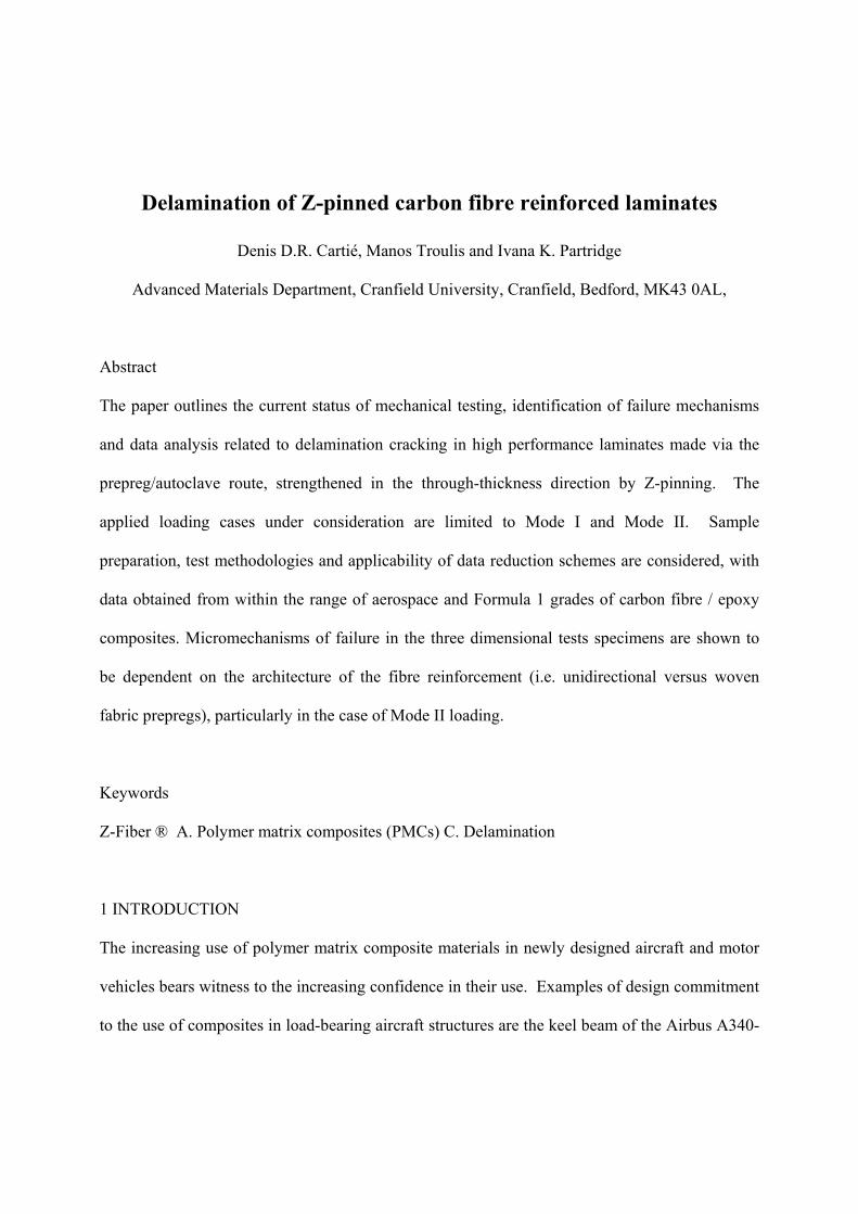
central loading pin and is stopped artificially. The data reduction scheme used to generate the R-
curves shown in Fig.5. is the so called ‘experimental compliance calibration’ method. The change
in compliance with crack length for any given specimen is determined in a separate experiment ,
prior to fracture testing. Whilst the absolute values of ‘GIIC’ cannot be used for anything other
that comparative purposes, it is apparent from these results that a much increased resistance to
crack propagation may be expected to result from the action of the Z-pins on the cracking beam
under these particular loading conditions.
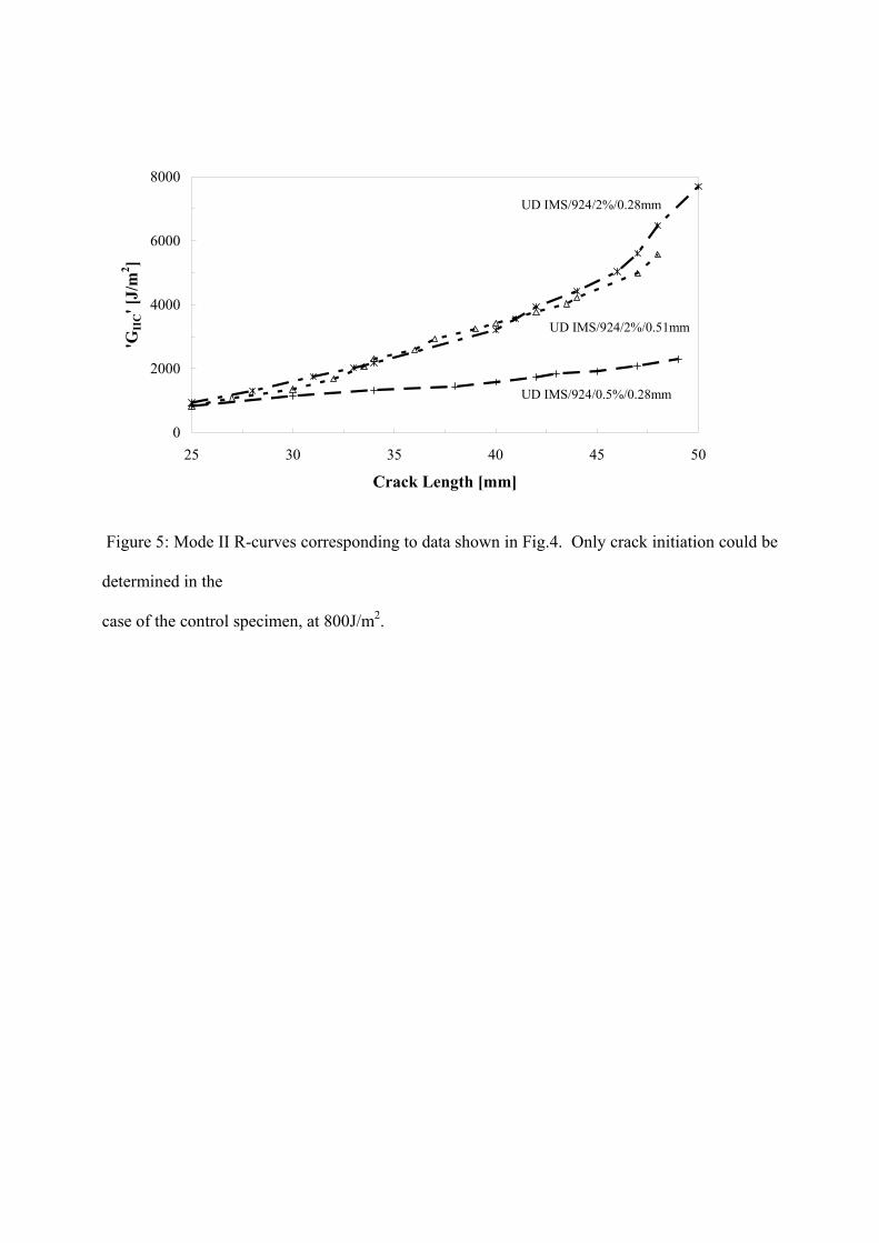
Fig. 6 is a side view of the deformation of Z-pins under load, in a miniaturised Z-pinned beam
under 3point ENF loading. The Z-pin is able to bend into an S-shape and appears to be pulling

away from the top surface of the composite arm. For this to be possible, it is assumed that the Z-
pin would have debonded from the surrounding composite. It is to be noted that an observable
opening of the delamination crack exists, indicating a significant contribution of crack opening in
the loading spectrum of this sample. This point becomes relevant in the following sections.
3.3 Double lap shear joint
A double lap shear joint, of a configuration shown in Fig.7, was made from Woven T300/M21
prepreg and the overlaps were reinforced with 2%/0.51 mm Z-pin blocks. The crack starter areas
(see Fig.7) were released by the inclusion of the same crack starter film as used in the DCB tests,
to minimise the chance of high elastic energy being stored at a blunt crack tip and subsequent
totally catastrophic failure. When tested in longitudinal tension, this type of specimen showed no
improvement over the control (unpinned) sample, in terms of the load carrying capability or of
the strain to failure. There is an obvious need to reconcile this observation with the results shown
in section 3.2.
The relatively thick (6mm) double lap shear joint has a low compliance, compared to the 3mm
thick standard DCB beams. There is clearly a considerable stress concentration at the corners
and the crack propagation has to be expected to be rapid, in comparison with the DCB tests.
Nevertheless, some effect of the bridging action of the Z-pins may have been expected.
The hypothesis is that the crack opening displacement, visible in the DCB samples of Fig. 6, is
severely limited in the thick double lap shear specimen. Thus the Z-pins may not be able to pull
out from the specimen arms and will fail by transverse shear only.
3.4 ‘Z-shear’ test

A new form of mechanical test was developed in the authors’ laboratory, designed to investigate
the above hypothesis. The essence of this new ‘Z-shear’ test is described by Fig. 8. The test rig
imposes shear loading onto a block of Z-pins contained in a composite specimen while
constraining the allowed opening displacement. The upper part of the rig is fixed to the load cell
and held in place by a steel loading pin and a locking nut. The downward motion of the lower
part introduces the shearing load. To prevent damage of the load cell, as well as any errors in the
measurement due to any unwanted lateral loads, a rolling steel cylinder is added to the upper part
of the rig supported only by contact forces against a rigid extension of the machine frame. No
additional friction forces are imposed on the load cell as the cylinder is free to move and rotate.
The sliding displacement is measured using both the crosshead extension and a clip gauge.
It is important to note that the cured specimens have an insert film in the mid- plane and are thus
held together only by the bridging Z-pins. Two different laminate fibre architectures were
investigated, using UD IM7/M21 and Woven T300/M21 prepregs. Nominal specimen thickness
is 6.6mm for Woven T300/M21, and 6mm for UD IM7/M21. The Z-pin insertion direction was
ensured to be normal to the plane of the specimen. Combinations of different Z-pin densities and
Z-pin diameters were considered. The maximum number of Z-pins contained in each specimen
was dictated by the capacity of the 5kN load cell used. The measured resistance force is
normalised by the number of pins in the presentation of the results. Representative data are
shown in Fig.9 in the form of normalised load-displacement traces. There is a striking difference
between the response obtained from unidirectionally reinforced Z-pinned specimens and woven
fabric Z-pinned specimens. The maximum load per pin which the specimen can carry is higher
for the larger diameter pins (as expected). For a given pin diameter the maximum load is about
double in the case of the woven fabric substrate samples, compared to the UD samples.

However, the lower load, carried by the UD samples, can be carried over a considerably greater
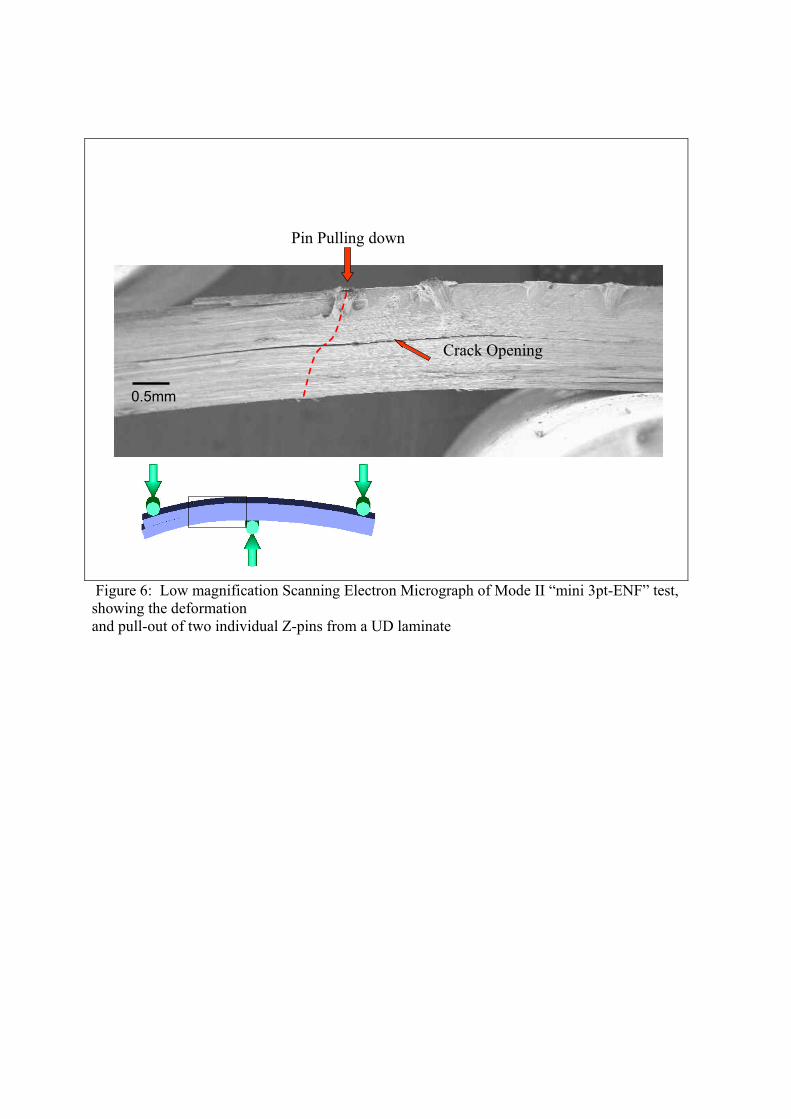
sliding displacement. Fig.10 displays SEM images of failed 0.28mm diameter Z-pins for the UD
and the woven fabric samples. The Z-pin is able to plough through the resin rich area within its
own resin pocket in a UD sample, while its movement is significantly constrained within the
woven fabric sample. Extensive internal splitting and pullout of the individual fibres constituting
the Z-pin is evident in the UD sample; a transverse shear type of failure dominates the failure of
the Z-pin in the woven fabric sample.
4 DISCUSSION
The test methods relating to the crack opening (Mode I) loading case are developed sufficiently
to provide reliable data for analytical or FE models of localised behaviour in Z-pinned structures.
A further improvement of the accompanying data analysis is underway, using lateral stress
distributions around the crack tip to mimic a distributed action by localised bridging elements
[14]. The successful treatment of the Mode I loading case is largely due to the dominance of a
single simple micromechanical mode of failure, namely Z-pin debonding and pullout, on the
energy absorption under Mode I loading conditions. This dominance is in part a consequence of
the fact that the energy associated with Mode I cracking of the resin itself is considerably lower
that the energy associated with the pin debond and pullout.
In contrast, the response of a Z-pinned laminate to shear loading (nominally Mode II) is a
complex superposition of the crack propagation resistance of the resin matrix itself (roughly five
times higher than in the Mode I case) and of a multiplicity of failure micro-mechanisms of the Z-
pins bridging the crack. From the above presented findings, it appears that the response of Z-
pinned composite specimens to (nominally) Mode II loading depends strongly upon the crack
opening displacement and on the fibre reinforcement material type. The crack opening constraint

can be expected to be dependent mainly on the testing fixture, but there is evidence to suggest
that the Z-pins themselves contribute to the crack opening displacement, by pushing the crack
faces apart.
As a more general case Fig.11 illustrates the spectrum of failure types that a single Z-pin can
undergo under shearing loading conditions. Ideally, the pair of shearing forces lies on parallel
axes marginally distanced from each other. As the distance between them increases, the ratio of
bending to shear (of the Z-pin) increases. The distance between the applied forces depends on the
ply geometry of the laminate. A resin rich area surrounds the Z-pin. The Z-pin can crush the resin
and plough into the resin rich area under lateral loading. Laminate fibres at a 0° angle relative to
the lateral displacement of the Z-pin provide little constraint, while fibres at a 90° angle provide
the most. The amount of constraint will therefore vary with fibre orientation above and below the
displacement (or delamination) plane. This would explain the significant difference in the extent
of Z-pin ‘ploughing’ noted between woven fabric and UD specimens.
The highly orthotropic properties of the Z-pins tend to favour failure in longitudinal shear
(splitting) under lateral loading. Splitting separates the Z-pin into numerous individual fibre
bundles or even individual fibres. Since the diameter of each Z-pin constituent fibre is
significantly smaller than the Z-pin diameter (7-10µm compared to 0.28 or 0.51 mm), the
bending to shear loading ratio increases further. If a debonded Z-pin undergoes initial pullout, the
change in the frictional traction on the Z-pin as it is pressed against the constraining laminate
(also called ‘snubbing’ effect [12]), will limit further pullout. Many samples show delamination
planes with failed Z-pins protruding marginally from both fractured surfaces.
In conclusion, it appears that the failure micromechanisms in Z-pinned specimens, under a
combination of lateral and longitudinal displacements, are a complex combination of Z-pin
pullout, fibre fracture, resin fracture and resin crushing. The total energy absorption involved in

the failure process then depends upon this balance. Further work is underway in the authors’
laboratory to quantify the relative contributions of each of the failure micromechanisms to the
overall delamination process.
ACKNOWLEDGEMENTS
The work reported here was funded by DTI CARAD program and by EPSRC (GR/R 90369), via
Faraday Advanced.
REFERENCES
1. Cabanac JP, La recherche composite à Aerospatiale Matra Airbus – Application sur la
poutre ventrale A340-600. 12ieme Journées Nationales sur les Composites proceedings,
Cachan, France, 2000 ; ed. O. Allix, C. Cluzel & J. Lamon.
2. McBeath S, Safety Pins. Int J. Racecar Engineering, 2002; 12: 56-62.
3. Tong L, Mouritz AP and Bannister MK, 3D Fibre Reinforced Polymer Composites.
Elsevier, 2002; ISBN 0-08-043938-1.
4. Partridge IK, Cartié DDR and Bonnington T, Manufacture and performance of Z-pinned
composites. Ch 3 in Advanced Polymeric Materials: Structure-property relationships; eds.
Advani S., Shonaike G., CRC Press, April 2003; ISBN 1-58716-047-1.
5. Cartié DDR, Effect of Z-Fibres™ in the Delamination Behaviour of Carbon Fibre / Epoxy
Laminates. PhD Thesis, Cranfield University, Advanced Materials Department, 2000.

6. www.aztex-z-fiber.com
7. Cartié DDR, Brunner AJ and Partridge IK, Effects of mesostructure of Z-pinned
laminates on their crack control characteristic. 3rd ESIS TC4 Conference on Fracture of
Plastics, Adhesives and Composites, Les Diablerets, Switzerland, 15th – 18th September
2002, ESIS Publication 32. Fracture of Polymers, Composites and Adhesives II Editors:
Blackman BRK, Pavan A & Williams JG, Elsevier Science 2003. ISBN: 0-08-044195-5.
8. Yan W, Liu HY and Mai YW, Numerical study on the mode I delamination toughness of
Z-pinned laminates. Comp Sci tech 2003; 63, 1481-1493.
9. Grassi M and Zhang X, Finite Element Analysis of mode I interlaminar delamination in
Z-fibre reinforced composite laminates. Comp Sci Tech 2003; 63(12), 1815-1832.
10. Massabó R and Cox BN, Unusual characteristics of mixed mode delamination in the
presence of large scale bridging. Mech Composite Mater. Struct 2001; 8, 61-80.
11. Rugg KL, Cox BN and Massabò R, Mixed Mode Delamination of Polymer Composite
Laminates Reinforced Through the Thickness by Z-fibers. Composites A 2002; 33, 177-
190.
12. Cox BN, Snubbing Effects in the Pullout of Fibrous Rod from a laminate. Submitted to
Composites Part A, September 2003.

13. Blackman BRK, Kinloch AJ and Paraschi M, On the Mode II loading of Adhesives
Joints, 3rd ESIS TC4 Conference on Fracture of Plastics, Adhesives and Composites, Les
Diablerets, Switzerland, 15th – 18th September 2002, ESIS Publication 32. Fracture of
Polymers, Composites and Adhesives II Editors: Blackman BRK, Pavan A & Williams
JG, Elsevier Science 2003. ISBN: 0-08-044195-5.
14. Brunner AJ, Blackman BRK and Williams JG, Deducing Bridging Stresses and Damage
from GIC Tests on Fibre Composites, 3rd ESIS TC4 Conference on Fracture of Plastics,
Adhesives and Composites, Les Diablerets, Switzerland, 15th – 18th September 2002,
ESIS Publication 32. Fracture of Polymers, Composites and Adhesives II Editors:
Blackman BRK, Pavan A & Williams JG, Elsevier Science 2003. ISBN: 0-08-044195-5.
Figure 1: Three different Z-Fiber® preforms; from left to right 0.5%, 2% and 4%.

0
2000
4000
6000
45 55 65 75 85 95
Crack Length [mm]
GIC
[J/m
2 ]
ExperimentalFEA
UD IMS/924/2%/0.28mm
UD IMS/924/0.5%/0.28mm
UD IMS/924/2%/0.51mm
UD IMS/924/Control
Figure 2: Selected R-curves from Mode I tests on control and Z-pinned DCB specimens,
compared with
corresponding Finite Element Analysis results [4].
Pin1 Pin2 Pin3
0.5mm
Figure 3: Low magnification Scanning Electron Micrograph of Mode I “mini-DCB” test,
showing the de-bonding

and pull-out of three individual Z-pins from a UD laminate.

0
400
800
1200
0 2 4 6 8
Deflection [mm]
Load
[N]
UD IMS/924/2%/0.51mm
UD IMS/924/2%/0.28mm
UD IMS/924/Control
UD IMS/924/0.5%/0.28mm
Figure 4: Load vs. Deflection traces from Mode II 3pt ENF tests on UD samples.
0
2000
4000
6000
8000
25 30 35 40 45 50
Crack Length [mm]
'GII
C' [
J/m
2 ]
UD IMS/924/2%/0.51mm
UD IMS/924/0.5%/0.28mm
UD IMS/924/2%/0.28mm
Figure 5: Mode II R-curves corresponding to data shown in Fig.4. Only crack initiation could be
determined in the
case of the control specimen, at 800J/m2.
Pin Pulling down
Crack Opening
0.5mm
Figure 6: Low magnification Scanning Electron Micrograph of Mode II “mini 3pt-ENF” test, showing the deformation and pull-out of two individual Z-pins from a UD laminate

Fig 7 Schematic of a Z-pinned double lap shear specimen (by courtesy of S. Ferrari).
Insert Film as crack initiator
Z-Fibres®

Figure 8: Schematic of the Z-shear test rig.
PTFE
Laminate
Z-pins

.
Fig
. 9: N
orm
alis
ed lo
ad-d
ispl
acem
ent r
esul
ts fr
om th
e Z-
shea
r tes
t.
020406080100
120
140
01
23
45
67
8Sp
ecim
en D
ispl
acem
ent /
Z-p
in D
iam
eter
Load per pin [N]
Wov
en T
300J
/M21
/2%
/0.5
1mm
Wov
en T
300J
/M21
/2%
/0.2
8mm
UD
IM7/
M21
/2%
/0.2
8mm
UD
IM7/
M21
/2%
/0.5
1mm
Figure 10: Scanning Electron Micrographs of failure in a 0.28 mm diameter Z-pin under
shear loading in UD IM7/M21 (top) and Woven T300/M21 specimens (bottom).

23
Pullout Transverse shear failureInternal shear failure
Figure 11: Schematic representations and actual examples of different possible failure
modes of Z-pins under shear loading.


![Pinned sites in ie9 [beta]](https://img.dokumen.tips/doc/110x75/5554bdb8b4c90503388b4c9b/pinned-sites-in-ie9-beta.jpg)