Embed Size (px)
Citation preview

'DEl4
- .,
1riUtTLL JIC VSTtM 9O-2516
(NASA) 15 1)
CSC1 22B
Unci as _11 )' '' _•)
https://ntrs.nasa.gov/search.jsp?R=19900015844 2018-05-23T06:52:55+00:00Z
Space Shuttle Avionics System
ORIGINAL CONTAINS
COLOR ILLUSTRATIONS
NASA SP-504
Space Shuttle Avionics System
John F. Hanaway Intermetrics, Inc.
Robert W. Moorehead NASA Headquarters
NASANational Aeronautics and Space Administration Office of Management Scientific and Technical Information Division Washington, DC 1989

Library of Congress Cataloging-in-Publication Data
Hanaway, John F. Space shuttle avionics system / John F. Hanaway, Robert W.
Moorehead. p. cm. -- (NASA SP ; 504)
Supt. of Docs. no. : NAS 1.21:504 1. Space shuttles--Electronic equipment. I. Moorehead, Robert
W. II. Title. III. Series. TL3025.H36 1989 629.47--dc2O 89-600316
CIP
For sale by the Superintendent of Documents, U.S Government Printing Office, Washington, DC 20402

Preface
THE SPACE SHUTTLE avionics system represents a significant advance in avionics system technology. The
system was conceived in the early 1970's, developed throughout that decade, and became operational in the 1980's. Yet even today in 1988, it remains the most sophisticated, most advanced, most integrated avionics system in operational use in the aerospace arena. Some of the more significant "firsts" achieved by the system include the following.
0 I represents the first successful attempt to incorporate a comprehensive fail operational/ fail sale concept in an avionics system.
• It pioneered the development of complex redundancy management techniques, some of which rival the expert system approaches emerging today.
• It is the first operational aerospace system to use digital data bus technology to perform flight-critical functions.
• It is the first operational system to utilize a high-order language to develop and produce onboard software.
• It is the first operational aerospace program to make extensive use of flight software program overlays from a tape memory to expand the effective size of computer memory.
• It is the first system to integrate the flight control function with the rest of the avionics functions.
• It included the first use of digital fly-by-wire technology in an operational atmospheric flight application.
• It is the first avionics system to use a multifunction cathode-ray-tube display and crew interface approach.
• It is the first avionics system to provide extensive operational services to onboard nonaviomcs systems.
Such pioneering innovations and concepts are remark-able in that they emerged in a design environment which would be considered archaic by today's standards. For instance, the data processing state of the art has turned over at least four times since the Space Shuttle design was conceived. In 1974, there were no off-the-shelf microcom-puters, large-scale integrated-circuit technology was emerging but immature, and the use of data buses for critical
functions was considered to be radical and of high risk. Prior to the Space Shuttle, aerospace systems were made up of an essentially independent collection of subsystems, organized along disciplinary lines such as flight control, guidance and navigation, communications, and instrumen-tation. Each subsystem typically had its own dedicated controls, displays, and command and signal paths. The Space Shuttle avionics system not only integrated the computational requirements of all subsystems in one central computer complex, but introduced the concept of multifunction controls, displays, and command/ data paths.
The overall system design was driven by mission requirements and vehicle constraints never before encoun-tered in a space program. Significant among these were the following.
• The requirement for multiple reuse over a 20-year period - The economic and safety-related impacts of aborting alter one failure required that the system have a two-fault-tolerant fail operational/ fail sale configuration.
• The requirement that comparison of data or performance from independent systems or components operating in parallel be the primary means of detecting and isolating failures and assessing system operational status
- To detect the second failure in a system, four parallel strings were required and baselined.
- The use of built-in test was excluded wherever possible as a less reliable fault isolation technique.
• The requirement for an unpowered landing on a runway - The stringent performance required prohibited the use of degraded backup systems.
• The autonomy requirement - Large quantities of instrumentation data, transmitted to the ground on previous programs for spacecraft functional assess-ment and subsystem management, had to be processed onboard and made available to the crew in usable forms.
• The Space Shuttle vehicle which evolved was an unstable airframe requiring sufficient control authority to cause structural failure if an erroneously applied
PRECEDING PAGE BLANK NOT FILMED

SPACE SHUTTLE AVIONICS SYSTEM
hardover control actuator command was allowed to remain in effect for as little as 10 to 400 milliseconds.
- Full-time stability augmentation was baselined, direct control modes were excluded, and digital autopilots were designated to accommodate the wide spectrum of control.
- Manual intervention or switching of active/ standby strings proved inadequate to overcome the effects of erroneous hardover commands; therefore, a system approach was baselined in which hardovers were prevented through the use of multiple, parallel-operating, synchronized processors and command paths to drive force-summing control actuators.
• The large size of the Space Shuttle vehicle resulted in the weight of wire, both signal and power, being a significant proportion of the avionics system weight.
- Multiplexed serial digital data buses were used for command and data transmission throughout the vehicle.
Solid-state remote power control devices were used to reduce the quantity of power cable needed.
A myriad of other mission, vehicle, and system require-ments influenced or dictated various aspects of the design; however, the basic system concepts were derived from those described.
The Space Shuttle avionics system which evolved features a five-computer central processing complex, which provides software services to all vehicle subsystems that require them. Each computer is connected to a network of 28 serial digital data buses, which distribute input/output commands and data to/from bus terminal units located throughout the vehicle. Dedicated hardware components, unique to the various subsystems, interface as necessary with bus terminal unit signal conditioning devices. During critical mission phases such as ascent and entry, the system is configured in four redundant, independent but synchronized strings, each controlling one-fourth of the redundant sensors and control effectors required for the operation in progress. A backup, simplex software package is installed in the filth computer to be used if a generic error causes failure of the total redundant set. During more benign mission phases such as on-orbit, the computer complex can be configured, by loading the appropriate software programs, to perform a wide variety of mission and payload support functions.
The system includes more than 270 components, depending on the mission, and uses approximately 500 000 lines of software code. Although very complex and difficult to describe or understand, the system has proven to be reliable, durable, extremely versatile, and a tribute to the multitudes who contributed to its design, development, and verification.
vi

Contents Section Page
1 INTRODUCTION Purpose of Document ..................................................................... Organization.............................................................................1 Use.....................................................................................1
THE DESIGN ENVIRONMENT Introduction............................................................................. Avionics Hardware! Software FlightControl ............................................................................ Guidance and Navigation .................................................................. Displays and Controls ..................................................................... Communications and Tracking ............................................................. Redundancy Management..................................................................
SYSTEM DESIGN EVOLUTION Introduction............................................................................. 5
Top-Level Design Drivers! Requirements ..................................................... 5
DataProcessing .......................................................................... 9 FlightControl ............................................................................ 10 BackupSystem ........................................................................... 12 Redundancy Management.................................................................. 12 Onboard System Management .............................................................. 13 Navigation............................................................................... 15 Displayand Control .................................................................. ...... 17 Communications.......................................................................... 17 USAF Requirements ...................................................................... 19 PayloadSupport.......................................................................... 19 Remote Manipulator ...................................................................... 20 PowerDistribution........................................................................ 20
SYSTEM MECHANIZATION/ OPERATION Overview................................................................................21 Avionics System Functions .................................................................22 Data Processing ..........................................................................25 Display and Control.......................................................................35 Guidance, Navigation, and Control ..........................................................38 Sequencing.............................................................................. 45
System Management/ Instrumentation .......................................................47 Communications and Tracking .............................................................49 Payload Support Operations ...............................................................54 Electrical Power Distribution and Control ....................................................56 GroundCheckout .........................................................................59
APPENDIX - ACRONYMS/ABBREVIATIONS .....................................................61
VII
SPACE SHUTTLE AVIONICS SYSTEM
Tables
Table Page
44 Data Bus Utilization ......................................................................30
4-I1 Guidance, Navigation, and Control Elements .................................................39
Figures
Figure Page 3-1 Elevon failure effects ....................................................................... 6 3-2 Four-port actuator........................................................................ 7 3-3 Baseline system approach .................................................................. 7 3-4 Active/standby approach .................................................................. 8 3-5 Parallel string approach ................................................................... 9 3-6 System management approaches ............................................................ 14 3-7 Skewed IMU approach .................................................................... 15 4-1 Avionics equipment locations............................................................... 21 4-2 Avionics functional categories .............................................................. 22 4-3 Ascent control effectors.................................................................... 23 4-4 Ascent trajectory ......................................................................... 23 4-5 Entry trajectory .......................................................................... 24 4-6 Terminal area energy management .......................................................... 25 4-7 Final approach ........................................................................... 25 4-8 Listen mode ............................................................................. 26 4-9 Memory configurations .................................................................... 27 4-10 OPS substructure ......................................................................... 27 4-11 Software architecture...................................................................... 28 4-12 GPC memory configuration ................................................................ 28 4-13 Data bus characteristics ................................................................... 29 4-14 Data bus message formats ................................................................. 29 4-15 Data bus architecture ..................................................................... 30 4-16 Multiplexer/demultiplexer block diagram ..................................................... 31 4-17 Master events controller ................................................................... 32 4-18 Engine interface unit ...................................................................... 33 4-19 Annunciator display unit .................................................................. 34 4-20 Data bus control ......................................................................... 35 4-21 Forward flight deck ....................................................................... 36 4-22 Aft flight deck............................................................................ 37 4-23 Display and control block diagram ........................................................... 38 4-24 GN&C RM configuration .................................................................. 40 4-25 Air data system........................................................................... 41 4-26 GN&C actuator configuration .............................................................. 42 4-27 Typical hydraulic actuator drive ............................................................ 43 4-28 Main engine throttle control................................................................ 44 4-29 RCS configuration ........................................................................ 45 4-30 OMS configuration ....................................................................... 46 4-31 Sequencing configuration .................................................................. 46 4-32 Instrumentation system .................................................................... 47 4-33 System management configuration .......................................................... 48 4-34 Orbital communication links ............................................................... 49 4-35 Atmospheric flight links ................................................................... 49 4-36 Hardware groupings ...................................................................... 50
vii'

CONTENTS
Figure Page
4-37 Antenna locations 50 ............................................................4-38 S-band network equipment ...................................................... 51 4-39 S-band network services ........................................................ 52 4-40 S-band payload communications .................................................. 52 4-41 Ku-band radar/ communication subsystem ........................................... 53 4-42 Audio distribution system ....................................................... 54 4-43 Navigation aids .............................................................. 54 4-44 Payload interfaces ............................................................ 55 4-45 Electrical power system (single string) .............................................. 57 4-46 Essential bus distribution (one of three) ............................................. 58 4-47 Control buses ............................................................... 59 4-48 Checkout configuration ........................................................ 59
Ix
Section 1 Introduction
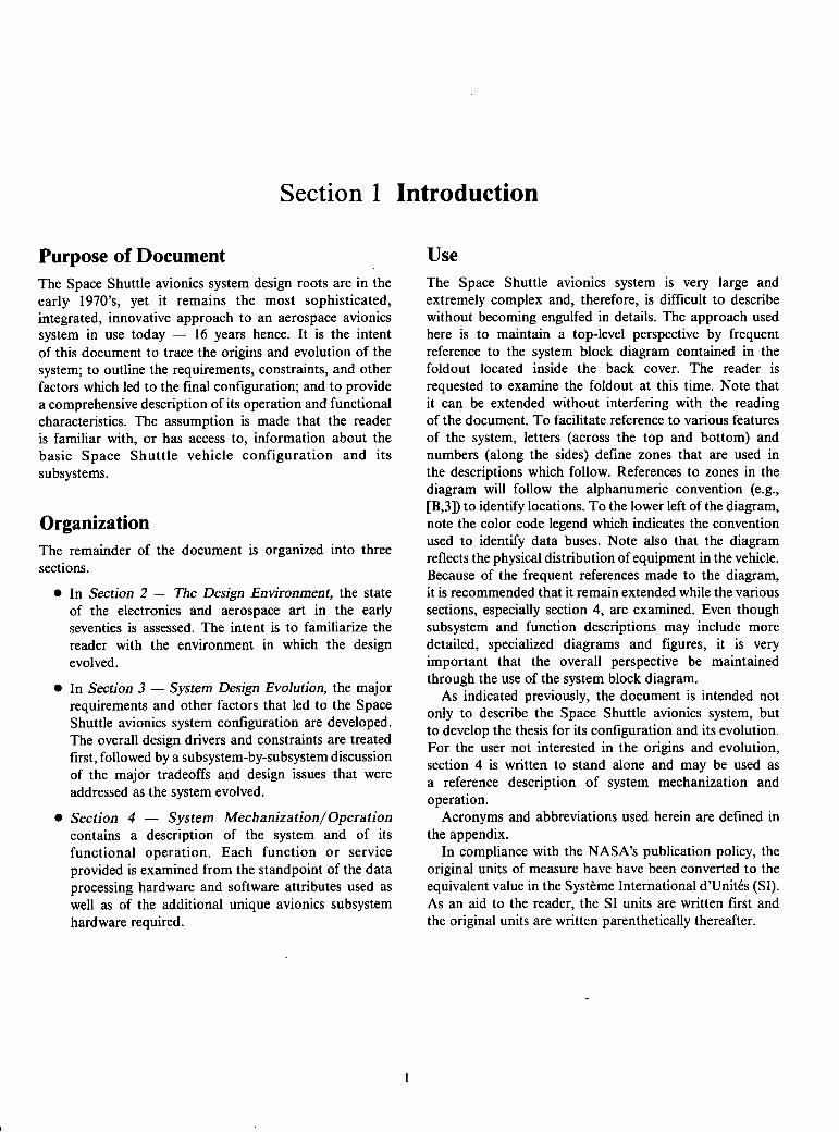
Purpose of Document The Space Shuttle avionics system design roots are in the early 1970's, yet it remains the most sophisticated, integrated, innovative approach to an aerospace avionics system in use today - 16 years hence. It is the intent of this document to trace the origins and evolution of the system; to outline the requirements, constraints, and other factors which led to the final configuration; and to provide a comprehensive description of its operation and functional characteristics. The assumption is made that the reader is familiar with, or has access to, information about the basic Space Shuttle vehicle configuration and its subsystems.
Organization The remainder of the document is organized into three sections.
• In Section 2 - The Design Environment, the state of the electronics and aerospace art in the early seventies is assessed. The intent is to familiarize the reader with the environment in which the design evolved.
• In Section 3 - System Design Evolution, the major requirements and other factors that led to the Space Shuttle avionics system configuration are developed. The overall design drivers and constraints are treated first, followed by a subsystem-by-subsystem discussion of the major tradeoffs and design issues that were addressed as the system evolved.
• Section 4 - System Mechanization/ Operation contains a description of the system and of its functional operation. Each function or service provided is examined from the standpoint of the data processing hardware and software attributes used as well as of the additional unique avionics subsystem hardware required.
Use The Space Shuttle avionics system is very large and extremely complex and, therefore, is difficult to describe without becoming engulfed in details. The approach used here is to maintain a top-level perspective by frequent reference to the system block diagram contained in the foldout located inside the back cover. The reader is requested to examine the foldout at this time. Note that it can be extended without interfering with the reading of the document. To facilitate reference to various features of the system, letters (across the top and bottom) and numbers (along the sides) define zones that are used in the descriptions which follow. References to zones in the diagram will follow the alphanumeric convention (e.g., [B,3]) to identify locations. To the lower left of the diagram, note the color code legend which indicates the convention used to identify data buses. Note also that the diagram reflects the physical distribution of equipment in the vehicle. Because of the frequent references made to the diagram, it is recommended that it remain extended while the various sections, especially section 4, are examined. Even though subsystem and function descriptions may include more detailed, specialized diagrams and figures, it is very important that the overall perspective be maintained through the use of the system block diagram.
As indicated previously, the document is intended not only to describe the Space Shuttle avionics system, but to develop the thesis for its configuration and its evolution. For the user not interested in the origins and evolution, section 4 is written to stand alone and may be used as a reference description of system mechanization and operation.
Acronyms and abbreviations used herein are defined in the appendix.
In compliance with the NASA's publication policy, the original units of measure have have been converted to the equivalent value in the Système International d'Unités (SI). As an aid to the reader, the SI units are written first and the original units are written parenthetically thereafter.
Section 2 The Design Environment
Introduction To understand the configuration and makeup of the Space Shuttle avionics system, it is necessary to understand the technological environment of the early seventies. In the approximately 16 years since the inception of the system, computers and the associated technology have undergone four generations of change. If the system designers were operating in today's environment, a much different set of design choices and options would be available and, quite possibly, a different configuration would have resulted. This section is intended to familiarize the reader with the designer's world during the formative stages of the system, with the technology available, and with the pressure of factors other than technology which influenced the result.
Although the state of technology was a major factor (and limitation) in the design of the avionics system, the effect of other factors was also significant. These include influences arising from traditional, conservative attitudes, as well as those associated with the environment in which the system was to operate. In any development program, a new approach or technique is correctly perceived to have unknown risks with potential cost and schedule implications and is to be avoided whenever possible. In addition, the designers, the flightcrew, and other operational users of the system often have a mindset, established in a previous program or experience, which results in a bias against new or different, "unconventional" approaches. Finally, the environment in which the system is to function must be considered. For instance, a new technique proposed for a system may not be viable if it requires a major change in the associated ground support complex. In the following paragraphs, a number of subsystem or functional areas are examined in the context of one or more of these factors.
Avionics Hardware! Software In the early seventies, only two avionics computers under development were considered potentially capable of performing the Space Shuttle task. These were the IBM AP-101 (a derivative of the 4n technology used in various military and NASA flight programs) and the Singer-Kearfott 5KC-2000 (then a candidate for the B-IA program). Both of these machines were judged to require extensive modification before being considered adequate.
No suitable off-the-shelf microcomputers were then available (no Z80's, 8086s, 68000's, etc.). Large-scale integrated-circuit technology was emerging but not considered mature enough for Space Shuttle use. Very little was known about the effects of lightning or radiation on high-density solid-state circuitry. Core memory was the only reasonably available choice for the Space Shuttle Orbiter computers; therefore, the memory size was limited by power, weight, and heat constraints. Data bus technology for real-time avionics systems was emerging but could not be considered operational. The U.S. Air Force (USAF) was developing MIL-STD-1553, the data bus standard, but it would not become official until 1975. All previous systems had used bundles of wires, each dedicated to a single signal or function. The use of tape units for software program mass storage in a dynamic environment was limited and suspect, especially for program overlays while in flight. Software design methodology was evolving rapidly with the emerging use of top-down, structured techniques. No high-order language tailored for aerospace applications existed, although NASA was in the process of developing a high-order software language for Shuttle (H AL! S), which subsequently become the Space Shuttle standard.
Flight Control In all manned space programs preceding the Space Shuttle (Mercury, Gemini, and Apollo), fly-by-wire control systems were used for vehicle attitude and translation control. Although digital autopilots were developed for Apollo spacecraft, analog control systems were also included and considered necessary for backup. Aircraft flight control technology, however, had not advanced beyond the use of mechanical systems, augmented with hydraulic boost on large airplanes. Most aircraft applications of electronics in the flight control system used limited-authority analog stability-augmentation devices to improve aerodynamic handling qualities. Autopilots were also analog devices and also given limited authority. Neither the stability-augmentation function nor the autopilot was considered critical for safe flight when implemented in these configura-tions. The flight control hardware and subsystems were kept functionally and electrically separate from other electronic systems to the extent possible.
PRECEDING PAGE BLANK NOT FILMED
SPACE SHUTTLE AVIONICS SYSTEM
Guidance and Navigation Sophisticated guidance and navigation schemes and algo-rithms had been developed and used in the Apollo Program; therefore, the technology base appeared adequate for the Space Shuttle in these disciplines. Although a new guidance and navigation challenge was posed by the entry through landing phase, no state-of-the-art advances were deemed necessary.
Displays and Controls The pilot input devices in general use for aircraft control were a stick or a yoke/ wheel for roll and pitch, and rudder pedals for yaw. When hydraulic boost was used, elaborate sensing devices were included to provide the correct feedback to the pilot. Hand controllers without feedback and with only electrical outputs had been used in previous manned space programs; however, the application did not involve aerodynamic flight. Switches, pushbuttons, and other input devices were typically hardwired to the function, the box, or the subsystem that required the input. Displays were also hardwired, were generally mechanical, and were dedicated to the function served. Off-the-shelf horizontal and vertical situation displays, although electronically driven, utilized a mechanical presentation. Electronic attitude and directional indicator (EADI) technology was emerging but not in common use. Heads-up displays (HUD's) were also just emerging. The concept of multifunctional displays was immature and had never been used in an aerospace application. Many of the display and control design issues associated with management of a redundant system had never been addressed.
Communications and Tracking A very capable S-band communications system had been developed for use on the Apollo Program; however, it could not serve the data rate, link margins, and coverage require-
ments forecast for Space Shuttle operations and experiment support. The NASA had led research in digital voice and sophisticated encoding and decoding techniques, but these had never been proven in an operational system. Solid-state radiofrequency (RF) amplifiers capable of power output sufficient for skin-tracking radar were emerging but also not proven. The Federal Aviation Administration (FAA) was considering an upgrade of the Instrument Landing System (ILS) to one using microwave scanning beam techniques capable of meeting Orbiter landing performance requirements, but no realistic conversion schedule existed.
Redundancy Management The use of redundant systems to enable operation in the face of failures was common in both aircraft and space applications; however, all previous approaches used primary/ backup, active/ standby techniques which relied on manual recognition of faults and crew-initiated switchover to the alternate or backup system. Very little was known about the use and management of multiple sensors or other input devices and even less about multiple output devices such as hydraulic actuators. No aerospace project had even contemplated the automation of failure detection and recovery for large systems such as the reaction control system (RCS). The RCS required complex assessments of large numbers of temperature and pressure sensors, correlation with vehicle dynamic response to digital autopilot commands, and a variety of recovery options which depended on factors such as mission phase, propellant quantity, and available thruster configuration. The system which evolved required the use of techniques which rival those of expert systems being developed today.
Section 3 System Design Evolution
Introduction The Space Shuttle avionics system is the result of a number of years of studies, analyses, design tradeoffs, and iterations conducted by NASA and the Space Shuttle contractors. The design was affected by a variety of requirements and constraints including those imposed by the Space Shuttle vehicle and its systems, the mission and associated policies under which the flights were to be conducted, the USAF, the user community, and the state of technology as described previously. Many features or aspects of the system derived from experience on previous space programs, from the results of in-house NASA and contractor advanced development projects, and, in some cases, from arbitrary choices of the design community. Programmatic aspects such as cost, schedule, and the need to settle on a baseline early in the program also had a strong influence. It is the intent in this section to lead the reader through the most significant portions of this design process. In the discussion to follow, the top-level mechanization drivers which dictated the basic system architecture and design approach are addressed first. Then, the major tradeoffs or design issues which led to the particular mechanization aspects or important features of the system are examined.
Top-Level Design Drivers/Requirements Design drivers which affected or forced the overall system architecture and approach can be grouped into two categories: mission derived and vehicle derived. In the following subsections, each of these categories is explored and linked to a particular aspect or aspects of the system.
Mission-Derived Requirements
The basic Space Shuttle mission consists of lift-off from the NASA John F. Kennedy Space Center or from Vandenberg Air Force Base, ascent and insertion into low Earth orbit, performance of operations in support of various payloads, and descent to an unpowered landing on a 4572- meter (15 000 foot) runway. The significant differences between the Space Shuttle mission and those of previous programs include the requirement for much more complex and extensive on-orbit operations in support of a much wider variety of payloads and the requirement to make precisely controlled, unpowered, runway landings. These
requirements, coupled with the longstanding NASA rule that a mission must be aborted unless at least two means of returning to Earth safely are available, had a profound effect on the design approach. In previous programs, the concept of safe return could be reduced to a relatively simple process; i.e., managing a parachute landing in the ocean in the vicinity of recovery forces. Therefore, relatively simple backup systems were devised; these systems had severely degraded performance compared to the primary operational system but complied with the mission rule. In the Space Shuttle mission, however, the entry through final approach and landing maneuvers impose a performance requirement on the onboard systems as severe as that of any mission phase; therefore, backup systems with degraded perform-ance were not feasible. Further, the economic impact of frequently aborted missions on a user-intensive program such as Space Shuttle made a system which dictated an abort after one failure completely unacceptable. Therefore, a comprehensive fail operational/ fail safe (FO/ FS) system requirement was imposed. This requirement meant that the avionics system must remain fully capable of performing the operational mission after any single failure and fully capable of returning safely to a runway landing after any two failures. The FO/ FS requirement and the incapability of degraded backup systems to achieve a safe return dictated the use of multiple avionics "strings," each independent from a reliability standpoint but each with equivalent capability.
Another design constraint, derived from experience on previous programs, severely limited the use of built-in test equipment (BITE) as a means of component failure detection. Many cases of failures in the BITE circuitry, leading to false conclusions about the operability of a unit, had been experienced. The much preferred, and Space Shuttle selected, method of fault detection was to compare actual operational data produced by a device or subsystem with similar data produced by devices or subsystems operating in parallel and performing the same function. A minimum of three strings is required to guarantee the identification of a diverging or disabled unit using this comparison process, and a fourth string is needed to accommodate a second failure in the same area. The combination of this fault detection, isolation, and reconfiguration (FDIR) approach and the FO/FS requirement led to the quadruple redundancy which is prevalent in much of the Space Shuttle avionics system.
Up Failure
EIIIIIII
C) a)
C 0 >C a)o FU
C,) 0 0.
Ce
C C) W
0 C
-10
-5
+5
+10
+15
-0.5
0
+0.5
+1 +1.5
+2
SPACE SHUTTLE AVIONICS SYSTEM
A third mission-derived requirement which had a systemwide impact was autonomous operation, mandated by the USAF and established as a design goal by NASA to decrease operational costs by reducing the dependence on ground support. To manage Space Shuttle systems onboard required that much of the subsystem telemetry data, which had been sent only to the ground on previous programs, be processed and provided to the crew in appropriate, usable forms. Because of the complexity and size of the system, many of the onboard system management functions had to be automated to a significant degree and mechanized with an appropriate mix of crew involvement, assessment, and required action, depending on the mission phase and associated workload.
Vehicle-Derived Requirements
The Space Shuttle is made up of four separate and distinct physical elements: the Orbiter (including the Space Shuttle main engines), the external tank (El'), and two solid rocket boosters (SRB's). These elements are arranged for lilt-off in a side-by-side configuration, in contrast to the vertical launch stack of the Apollo and other previous spacecraft. Because only the Orbiter is totally recoverable, most of the avionics equipment is contained in this element, although some flight control sensors and control effectors are located in the SRB's.
The Space Shuttle vehicle is an unstable airframe which cannot be flown manually even for short periods during either ascent or entry aerodynamic flight phases without full-time flight control stability augmentation. This factor excluded any possibility of unaugmented, direct flight control approaches, either mechanical or fly-by-wire. Although briefly considered for postentry aerodynamic flight control early in the program, cable/ hydraulic boost systems were quickly eliminated because of weight considerations and mechanization difficulties, and an augmented fly-by-wire approach was baselined. Analog augmentation devices were also considered early in the program, particularly for entry; however, the wide spectrum of control required and the need to readily adapt to performance changes as the vehicle evolved discouraged their use. Digital flight control systems had been used with great success in the Apollo Program, and, although no aircraft system had been flown with one at the time, NASA was well aware of the advantages of such a system and chose digital flight control as the Space Shuttle baseline. The full-time augmentation requirement, however, placed the digital flight control computation system in the safety-critical path and dictated quadruple redundancy in this area.
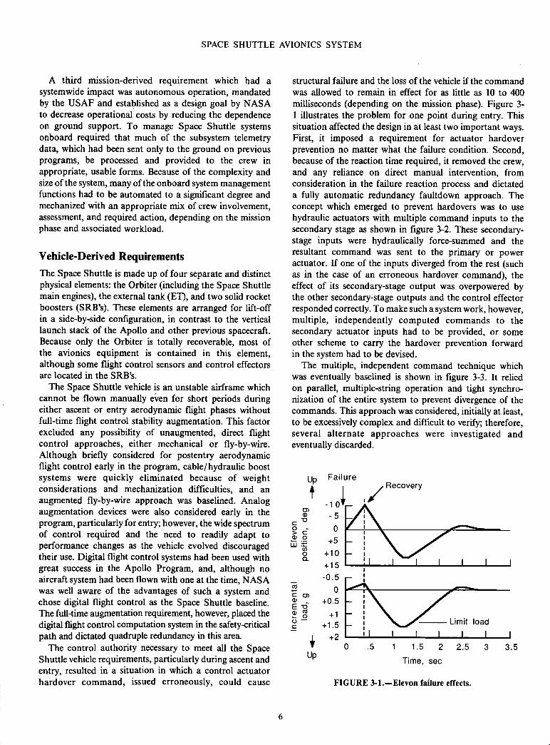
The control authority necessary to meet all the Space Shuttle vehicle requirements, particularly during ascent and entry, resulted in a situation in which a control actuator hardover command, issued erroneously, could cause
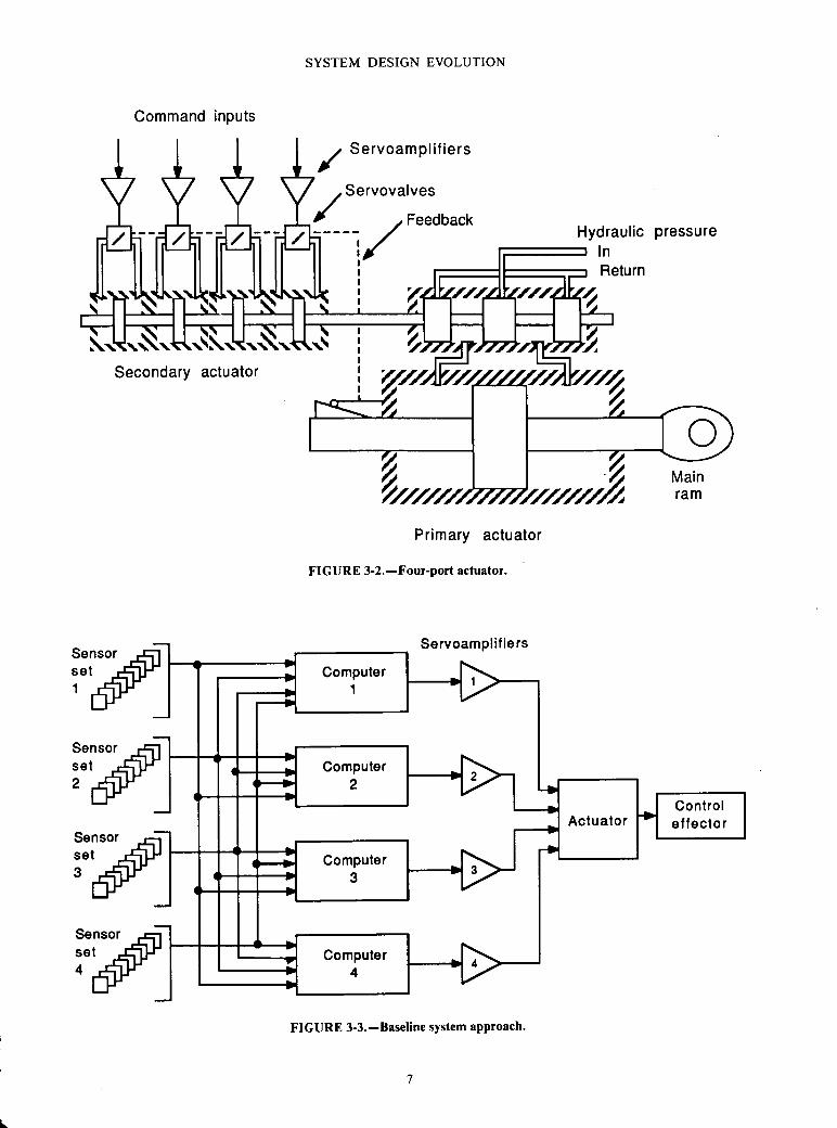
structural failure and the loss of the vehicle if the command was allowed to remain in effect for as little as 10 to 400 milliseconds (depending on the mission phase). Figure 3-I illustrates the problem for one point during entry. This situation affected the design in at least two important ways. First, it imposed a requirement for actuator hardover prevention no matter what the failure condition. Second, because of the reaction time required, it removed the crew, and any reliance on direct manual intervention, from consideration in the failure reaction process and dictated a fully automatic redundancy faultdown approach. The concept which emerged to prevent hardovers was to use hydraulic actuators with multiple command inputs to the secondary stage as shown in figure 3-2. These secondary-stage inputs were hydraulically force-summed and the resultant command was sent to the primary or power actuator. If one of the inputs diverged from the rest (such as in the case of an erroneous hardover command), the effect of its secondary-stage output was overpowered by the other secondary-stage outputs and the control effector responded correctly. To make such a system work, however, multiple, independently computed commands to the secondary actuator inputs had to be provided, or some other scheme to carry the hardover prevention forward in the system had to be devised.
The multiple, independent command technique which was eventually baselined is shown in figure 3-3. It relied on parallel, multiple-string operation and tight synchro-nization of the entire system to prevent divergence of the commands. This approach was considered, initially at least, to be excessively complex and difficult to verily; therefore, several alternate approaches were investigated and eventually discarded.
0 .5 1 1.5 2 2.5 3 3.5 Up
Time, sec
FIGURE 3-1.—Elevon failure effects.
Sensor
set4V
set
Sensor _e
Sensor
set/
Sensor
se
SYSTEM DESIGN EVOLUTION
Command inputs
Servoamplifiers
Servovalves
Feedback I;1F1;;11 /
I I
Hydraulic pressure =In = Return
Secondary actuator OF
Main ram
Primary actuator
FIGURE 3-2.—Four-port actuator.
.-_ _ __...._s:g:_.
FIGURE 3-3.—Baseline system approach.
7

SPACE SHUTTLE AVIONICS SYSTEM
One technique examined (fig. 3-4) would have used an active/standby approach with the active string supplying commands to all actuator inputs. An independent g-limiter and associated switch would be used to detect a structure-endangering situation and call for a manual or automatic switchover to a hot standby string. Several studies were conducted using this technique, which appeared promising at first, but it was eventually discarded because a number of problems were encountered. These included mechani-zation difficulty and the fact that the measurement cues varied throughout and between mission phases.
A second, also initially promising technique investigated is shown in figure 3-5. Using this approach, the independent strings would have operated in parallel, but very loosely coupled, with each operating on independent sensor data and each independently issuing commands to one of the actuator ports. Long-term divergence between systems would be prevented by periodically exchanging state vectors or other slowly varying information. Any short-term inner loop flight control command divergence would be compensated for with equalization in the actuator servomechanisms. This technique appeared feasible but was eventually discarded because its mechanization was very dependent on exact knowledge of vehicle characteristics and these, at the time, were in a constant state of flux. Further, no guarantee could be made that some future
vehicle modification would not perturb this concept unacceptably. Therefore, the current baseline endured, including multiple, active string operation with each string closely coupled and synchronized to prevent divergence of secondary actuator output commands.
Precise vehicle sequencing requirements also drove the system toward coupled, synchronized digital operation. These sequences included events such as Space Shuttle main engine (SSME) and SRB ignition, launch pad release and lift-off operations, SRB and ET stage separation, etc. These events are of the type which must occur within milliseconds of the correct time, but must absolutely be prevented from occurring at any other time. The baseline system approach, defined previously for flight control, also served the sequencing requirements for multiple, independent, simultaneous inputs and properly timed arm and fire sequences.
The large size of the vehicle also had an impact on the avionics system configuration. Because sensors, control effectors, and associated devices would be distributed all over the vehicle, the weight of the wire required to carry all the signals and commands necessary for operation of all system elements became a significant factor. Therefore, the use of multiplexed digital data buses was investigated and baselined. In addition, similar considerations led to the baselining of remote power control devices in lieu of
g - limiter switch
SenW
set I J Computer S' k 1 I I
I I I I
Sensor set
Computer
Sensor seJj Sensor se }4 ComputerJJ
Servoamplifiers
IControl Actuator effector
FIGURE 3-4.—Active/standby approach.

Sensor se
Sensor -,if
Seto
Sensor
2 8 W
Sensor set 3 01
SYSTEM DESIGN EVOLUTION
dedicated in-line circuit breakers in the crew cockpit area. In summary, the mission- and vehicle-derived require-
ments included the following.
• No degraded backup systems
• A fail operational/ fail sale approach
• Use of operational data to detect and isolate failures
• Quadruple redundancy to isolate a second failure
• Automatic failure detection and recovery for time-critical functions
• Full-time digital flight control
• Data buses and remote power control devices to save weight
• Onboard access to and analysis of subsystem data for autonomy
Data Processing As indicated in section 2, the state of technology in the early seventies severely limited the choices available in the data processing area. In the early stages of Space Shuttle development, a number of computer configurations were considered including options by which flight control was
segregated from guidance and navigation; the guidance, navigation, and control (GN&C) function was separated from other data processing system (DPS) functions; or aerodynamic ascent/entry and space-flight functions were mechanized in different machines. The considerations discussed previously, which led to a tightly coupled, synchronized FO/ FS computation requirement for flight control and sequencing functions, drove the system toward a four-machine computer complex. The difficulties involved in attempting to interconnect and operate multiple complexes of machines, possibly of different types and numbers, drove the configuration toward a single complex with central, integrated computation. A fifth machine was added in the final configuration, primarily because of uncertainty as to the future computation requirements which might be placed on the system. Initially, this computer was to be used to off-load nonessential mission applications, payload, and system management tasks from the other four. As will be seen, however, the fifth machine eventually became the host for the backup system flight software.
The size of the Space Shuttle computer memory to be baselined was significantly at issue in the beginning, with estimates running as low as 24k 32-bit words (k = 1024). Sixty-four thousand words of memory were eventually selected as the maximum which could be reasonably included considering the state of the art of computer design
State vector AxthannA
FIGURE 3-5.—Parallel string approach.
SPACE SHUTTLE AVIONICS SYSTEM
and vehicle weight, power, and thermal constraints. Memory limitations were a continuing problem throughout the early development phases and, as soon as technology permitted, the size was increased to 104k.
The program participants unanimously agreed that atop-down, structured methodology was the proper design approach for the Space Shuttle onboard software; however, the use of a high-order language and the selection of an operating system approach were subjects of significant controversy. The NASA had contracted for the develop-ment of HAL! 5, a high-order language tailored specifically for aerospace avionics applications, but the capability of it, or any other high-order language, to produce code with size, efficiency, and speed comparable to those of an assembly language program was questioned. The issue was resolved alter a competition, in which representative software routines were coded by different teams - one using HAL/S; the other, assembly language - showed that the approximate 10 percent loss in efficiency resulting from the use of the high-order language was insignificant when compared to the advantages of increased programmer productivity, program maintainability, and visibility into the software. Therefore, the use of HAL/S was baselined for all software modules except the operating system.
The operating system approaches in contention were a synchronous concept and a concept in which an asynchro-nous, priority-driven scheme was used. The synchronous approach afforded repeatability, predictability, and visibility into system operations, all attributes which ease testing and verification, but at the expense of adaptability for future growth. The asynchronous concept would readily accommodate growth but was more difficult to verify because it was not as predictable or repeatable. The concept that was finally baselined for the primary system software was a hybrid approach which incorporated a synchronous foreground executive structure and an asynchronous priority-driven background. This approach was considered to be more readily adaptable to any future requirements which might arise.
As indicated previously, data buses were baselined for Space Shuttle vehicle internal signal transmission; however, a number of design issues remained to be settled in this area. Based on advanced development work performed in NASA laboratories, a hall-duplex, biphase Manchester code, I-megabit data bus transmission technique had been selected but questions were raised as to the reliability of such a system to handle critical messages. Techniques for enhancing message correctness statistics were considered including the use of error-detecting codes such as Bose-Chaudhuri-Hocquenghen (BCH) and an echo or answering concept. Alter an analysis of the predicted word and bit error rates indicated that the basic system coding and message protocol would provide more than adequate signal reliability, an approach without additional protection was
baselined for all buses except those which interfaced with the main engine computers. (A design which used the BCH error-detecting code had already been baselined for this interface.) To ensure continued emphasis on performance in this critical area, the data buses and bus interface devices were procured as an integrated system from a single vendor. All other vendors whose subsystems used the data bus system were furnished these standard interfacing devices and required to install them in their line-replaceable units (LRU's).
The number of computer input/output (I/O) ports and associated data buses, and their functional allocation, was also the subject of much discussion in the early design phase. The total system bus traffic density could only be grossly estimated initially, and, because of the catastrophic effects on the system of reaching or exceeding the 1-Mbit/ sec bus limits, provisions for significant growth had to be included. The uncertainty in this area and the desire for functional isolation resulted in the baseline 24-bus port configuration, the maximum number which could reasonably be accommodated in the computer I/O processor. Allocation of these buses was based on a combination of factors including criticality, frequency of use, traffic density, and similarity of usage or function.
A summary of baselined requirements and approaches covered in this section includes
• A central five-computer complex
• A 64k memory size
• A top-down, structured approach to software design
• Use of HAL/S high-order software language
• An asynchronous, hybrid operating system approach
• A standardized data bus system procured as a system from a single vendor, with no Hamming-type error protection
• A 241/0 port and bus system, with functions allocated by criticality and use
Flight Control The circumstances which resulted in the choice of digital fly-by-wire control and the limitations on the use of manual direct modes have been described previously. Some other flight control areas which were at issue during the design phase included the following:
• Pilot/system response requirements and handling qualities
• Digital autopilot sampling rates and transport lags
• Sensor and actuator redundancy and location
• Entry gain scheduling, moding, and reconfiguration
• Autoland
10
SYSTEM DESIGN EVOLUTION
Specifications, requirements, and extensive treatments of response characteristics which would provide desired handling qualities for all types of aircraft were available in the Space Shuttle design era, but all dealt with conventionally powered aircraft operating in the subsonic or low-supersonic flight regimes. No specifications which treated the requirements for an unpowered aircraft operating over the entire orbital entry through landing envelope were available. In an attempt to establish an integrated set of such requirements, NASA convened a Space Shuttle Flying Qualities Symposium in early 1971 to solicit industrywide inputs and recommendations. These were subsequently published in a Space Shuttle Flying Qualities Specification and used as a guideline throughout the system development.
Some of the choices which directly affected the performance and stability of the control system included the selection of digital autopilot sampling rates and the minimum time delay or transport lag allowable between the receipt of inputs from manual controls and vehicle motion sensors and the issuance of commands to the control effectors. Because these factors were also fundamental drivers in the software design, particularly on the operating system, the selections had to be made very early in the program, well before substantive data on airframe performance and response characteristics became available. The digital autopilot experience base at the time was limited to that represented by the Apollo spacecraft, a vehicle which had no aircraft characteristics; therefore, the tendency was to take a conservative approach and set the sample rates very high —50 and 100 hertz were typical values proposed. Because rates of this order would have imposed a severe strain on the computer/ software complex, the pressure from the data processing community was to lower them as much as possible. The rate finally chosen was 25 hertz, the same as for Apollo, with a transport lag limit of 20 milliseconds, values which preliminary analysis indicated would provide for the required phase stabilization margins.
The flight control sensors installed in the Orbiter included rate gyros mounted on the aft payload bay bulkhead and body-axis-oriented accelerometers located in the forward avionics bays. The system was configured initially with three of each, with the tiebreaker in the event of a second failure to be calculated using data from the inertial measurement units (IMU's), which were located in front of the forward bays. This concept proved unworkable for the rate gyros because the distance between the IMU's and the rate gyros and the structural dynamics involved prevented accurate transfer of the inertial data. The IMU outputs were also initially baselined to break a tie between diverging signals from the body-mounted accelerometers. Again, the concept proved unworkable even though the instruments were located in the same vicinity, and a fourth string of each sensor was eventually incorporated.
It was also difficult to find an acceptable location for the rate gyros in both the Orbiter and the SRB's. An ideal location would have been at the center of gravity, mounted on structure the motion of which represented the true rigid-body rotation about that point. The nearest viable structure which reasonably approximated these conditions was the aft bulkhead of the payload bay. Therefore, the initial location of the rate gyro assembly was a mount on each of the four corners of this bulkhead, physically separated as much as possible for redundancy isolation. Subsequent ground vibration tests uncovered local resonances which made these locations unacceptable. The mounting location was changed twice before the present position at the center base of the bulkhead finally proved acceptable. The desire for physical separation of the redundant sensors was abandoned in favor of dynamically identical signals to avoid compromising the redundancy management selection logic. The rate gyro mounts in the SRB's also had to be modified after vibration tests uncovered unpredicted structural modes.
The hydraulic actuators used to position the engine gimbals and the aerodynamic control surfaces were triply redundant input port devices in the initial baseline. It proved to be very difficult to interconnect four computer-generated commands to a three-port actuator in a manner which would preserve the FO/FS requirement. The most straightforward solution was to mechanize four input ports and this configuration was eventually selected.
Design of the entry flight control system was a long and difficult process. The Orbiter requirement was unique in the high-performance aircraft development process in that the entire dynamic range of the vehicle from hypersonic through subsonic speeds would be encountered on the first orbital flight. In contrast, in the normal aircraft development approach, the flight envelope is gradually expanded in small, carefully controlled steps. The process was complicated by large data base uncertainties in predicted aerodynamic performance, including control surface effectiveness and other key parameters; in structural bending information; and in potential interaction between the RCS thrusters and the aerodynamic control surfaces. The control concept which evolved used RCS thrusters exclusively during very early entry, then gradually blended in the aerodynamic control surfaces as they became effective - first roll, then pitch, then yaw - until approximately Mach 3.5, when the thrusters were totally deactivated. Transitions between control laws, gain changes, etc., required because of the wide dynamic range, were scheduled on the assumption of best estimates of vehicle control response and performance obtained from the data base, using cues such as altitude, drag, and Mach number derived from the navigation and air data subsystems. Because of the data base uncertainties and because the systems used for cues had not yet been flight qualified (e.g., the air data
FE

SPACE SHUTTLE AVIONICS SYSTEM
system in particular was subject to large calibration uncertainties), a means for reacting in real time to off-nominal performance had to be provided to the crew. Three switches were installed for this purpose, each affording the opportunity to modify the system if anomalous performance was encountered. One switch opened the automatic guidance loop and reduced the flight control system gain by 6 decibels. Another selected a control law which did not require the use of yaw thrusters. The third provided the option of causing the transition from high to low angle of attack to occur either earlier or later than nominal.
Backup System As indicated previously, the Space Shuttle mission was not amenable to degraded backup system mechanizations, and, initially, no backup to the four-computer, four-string, FO/ FS avionics configuration was included. Eventually, however, considerations of potential generic software errors which could affect all four computers, and concern over the complexity of the primary system with its closely coupled, tightly synchronized approach forced a new look at the possibility of a backup. Constraints imposed on this investigation were that a backup system should in no way degrade the reliability or performance of the primary system, and that no significant crew training impact should result from the mechanization. The result was a concept which used the fifth computer, loaded with unique, independently developed and coded software capable of safe vehicle recovery and continuation of ascent or safe return from any mission situation. A redundant, manual switching concept was devised by which control of all required data buses, sensors, effectors, and displays was transferred to the single backup computer.
Redundancy Management The Space Shuttle Program pioneered the development of modern redundancy management techniques and concepts. Although previous space programs used backup systems, they were usually dissimilar and generally degraded in performance with respect to the prime system. The mission dynamics for the vehicles in these programs were such that active! standby operation with manual switching was adequate. Virtually all system functional assessment was performed on the ground using telemetry data. Only information required for immediate switchover decisions or other such actions was presented to the crew. The Space Shuttle system, however, presented a much different situation to the designer. The FO/ FS requirement, the drive toward onboard autonomy, and the rapid reaction times which prohibited manual assessment and switching were factors that had never before been seriously considered. In addition, the avionics system was required, for the first
time, to assess the performance and operational status of and to manage the redundancy included in nonavionics subsystems such as propulsion, environmental control, and power generation. As might be expected in such a situation, numerous design issues arose, a number of false design starts had to be overcome, and a process thought initially to be relatively simple proved to be extremely complex and troublesome. Many of these issues are discussed in other sections as part of the treatment of individual subsystems and functions. Only the more general, comprehensive topics are included here.
The initial concept for managing redundant units was simply to compare redundant data, discard any input which diverged beyond an acceptable threshold, and select the middle value if there were three good inputs (or the average if only two were available). The keyword in this sentence is "simply," for virtually nothing proved to be simple or straightforward in this process. First, measures had to be taken to ensure that the data set to be compared was time homogeneous, that each value was valid from a data bus communication aspect, and that the data were valid in the sense of a tactical air navigation (tacan) lockon. The selection process had to be capable of correctly handling four, three, two, or even single inputs, and of notifying the user modules or programs of the validity of the resultant output. The fault-detection process had to minimize the probability of false alarms while maximizing the probability of detecting a faulty signal; these two totally contradictory and conflicting requirements made the selection of the threshold of failure extremely difficult. The fault isolation and recovery logic had to be capable of identifying a faulty unit over the complete dynamic range to be experienced in the data, of accounting for any expected unique or peculiar behavior, and of using BITE when faulted down to the dual-redundancy level. Finally, the system had to accommodate transients, degrade as harmlessly as possible, and provide for crew visibility and intervention as appropriate.
It soon became apparent that each LRU, subsystem, and function would have unique redundancy management requirements and would therefore have to be treated individually. It also became apparent that, to provide the required emphasis and expertise, redundancy management would have to be treated as a function and assigned to a design group with systemwide responsibility in the area. Some of the more difficult design issues faced by this group are explored in the following paragraphs.
As indicated previously, the selection of thresholds at which to declare a device disabled proved to be a very difficult process. In an attempt to minimize false alarms, performance within 3o of normal was established as the allowable threshold level for a parameter and X 3cr as the allowable difference between compared parameters. In most cases, however, the standard deviation u had to
12

SYSTEM DESIGN EVOLUTION
be derived analytically either because of insufficient test data or because the hardware test program was not structured to produce the required information. In some other cases, the system performance requirements precluded operation with an input at the 3u level and the tolerance had to be reduced, always at the risk of increasing the false alarm rate.
Another task that proved difficult was mechanization of the fault isolation logic for system sensors such as rate gyros which, during the on-orbit phases, normally operated close to null. Under these conditions, a failure of a unit to the null position was equivalent to a latent failure and proved impossible to detect even with quadruple redun-dancy. It could subsequently result in the isolation of a functioning device, or even two functioning devices if two undetected null failures occurred.
The first remedy for this anomaly prevented the erroneous isolation but resulted in a significant increase in RCS fuel usage, caused by frequent switching between selected signals which effectively introduced noise into the flight control system. The final solution, which prevented the anomalous performance, was immensely more complex than was the original "simple" approach.
The redundancy management design process followed initially was to treat each system and function individually, tailoring the process to fit, then proceeding on to the next area. This compartmentalized approach proved inadequate in a number of areas in which the process cut across several subsystems, functions, and redundancy structures. A prime example is the RCS, which contains propellant tanks, pressurization systems, manifolds and associated electrically operated valves, and 44 thrusters used for flight control. The thrusters are divided into four groups, any two of which are sufficient to maintain vehicle control about all axes in all flight conditions. The other components (tanks, manifolds, valves, etc.) are also structured for fault tolerance. Each of the thruster groups and associated manifold valves is managed by one of the four redundant avionics strings. Layered on top of this already complex structure are the three electrical power buses, which distribute power throughout the system; the dual instrumentation system, which contains a number of the sensors that provide insight into certain aspects of system operation; and the displays and controls required for crew monitoring and management. The redundancy manage-ment logic must detect and isolate thrusters that are failed off, failed on, and leaking. Depending on the type of failure detected, the system must command appropriate manifold valves to prevent loss of propellant or any other dangerous condition.
Obviously, a compartmentalized approach to the redundancy management design would have been inade-quate for this system. Even with the comprehensive approach, employed by the task group in an attempt to
cover all aspects of system operation, the design has been repeatedly refined and augmented as ground test and flight experience uncovered obscure, unanticipated failure modes.
Onboard System Management One of the goals of the Space Shuttle Program was to lower operating costs by eventually reducing the size and scope of the ground support team required, in all previous programs, to monitor and assess spacecraft and subsystem performance and functionality. To accomplish this goal, however, meant that major portions of a task, hitherto performed by hundreds of specialized experts, would have to be performed onboard by a relatively small crew already busy with mission operations and experiment support. A major challenge facing the Space Shuttle designers, therefore, was to devise an approach which would accommodate the onboard system management require-ment but which would not overwhelm the flightcrew. Further, the design would have to provide initially for full ground support capability with an orderly transition of the function onboard as the capability became validated by flight experience.
It quickly became obvious that the only way to avoid overtaxing the crew would be to automate much of the system monitoring and assessment task. Because the computational requirements could only be grossly estimated initially, the capability of the central computer complex to assimilate the load was questioned. Therefore, a tradeoff study was conducted to determine the relative merits of an integrated approach versus a separate, independent computer dedicated to system management. A corollary issue involved the data acquisition process. On previous programs, only that information required by the crew to operate the spacecraft or to respond to emergencies was made available onboard; the rest was reduced and analyzed on the ground. The traditional approach to onboard instrumentation was to install a network of sensors, transducers, pickoffs, and signal conditioners together with a telemetry processor, which acquired, formatted, and multiplexed data for transmission to the ground. The data set thus acquired contained all of the information required to perform a system assessment, but, because the instrumentation network was overlayed on and essentially independent of the onboard operating systems, many of the measurements were accessible only on the ground. For the Space Shuttle, provisions had to be made to make all required data accessible onboard as well.
Two computation and data acquisition options were examined. (See fig. 3-6.) In alternate 1, the traditional instrumentation system was augmented with the necessary computational resources to provide an essentially independent capability. In alternate 2, the data were provided to and assimilated in the operating avionics system
13

SPACE SHUTTLE AVIONICS SYSTEM
Communication Alternate 1 system
Instrumentation Dedicated
System PCM sensors/signal display conditioners
computer u
Downlink data only
General-purpose displays
Avionics system
computers
Operational sensors/ effectors
Communication Alternate 2 H system
(Baseline) I PCM Instrumentation
master
a
sensors/signal unit conditioners
Dat buffers
Downlink.4 I
System management data data
General -purpose displays
Operational sensors! effectors
Avionics system
computers
FIGURE 3-6.—System management approaches.
14
SYSTEM DESIGN EVOLUTION
and its computer complex. The difficulties involved in integrating another computer, the associated controls, and the required displays into the system discouraged consideration of a separate approach, and the problems of providing the necessary additional data to the operating system were also difficult to resolve. The design finally chosen, alternate 2, was to install data buffers in the instrumentation telemetry processors which could be accessed by all the central computers and thereby would provide a source for those measurements not already available in the operating systems. The system management function was initially relegated to the fifth computer in the central complex, the one not included in redundant-set operations. As the system matured, however, many of the system management functions proved to be critical and were transferred to the redundant complex.
Means for assessing and condensing the information into a reasonable set which could be readily assimilated and acted on by the crew remained as another issue. Critical-function management was incorporated into the redundant set, and automatic failure detection and response were mechanized where appropriate.
Overall system monitoring was accomplished by comparing the sensed valued of selected measurements against preset upper and lower limits, and, depending on the urgency, either switching to an alternate path or annunciating the situation to the crew for appropriate action. Cathode-ray-tube (CRT) display pages devised for each subsystem provided quick and concise monitoring capability. Other crew assistance features which were considered included switch monitoring to assure that the correct system mode and configuration for a given operational situation were established, communications antenna management controllable either from the ground or onboard to ensure optimum coverage with minimum crew involvement, and an extensive caution and warning system to provide alerts for any abnormal situation.
Navigation Several issues and design choices were addressed in arriving at the Space Shuttle navigation system baseline. One of the most controversial was the selection of an inertial measurement system. The two options considered were a system with triply redundant, mechanically gimballed platforms, and a strapdown approach, which included six skewed gyro/ accelerometer pairs oriented to provide multiple fault detection and isolation capability. At the time, several gimballed systems that could meet Space Shuttle requirements with some modification were in production. Although no six-gyro strapdown systems were in production, one existing design was fairly mature, and this approach appeared to offer significant advantages from a system redundancy aspect. The final selection of
a gimballed system was based on such factors as maturity, the number of near-production designs available, and the predicted cost of the respective gyros.
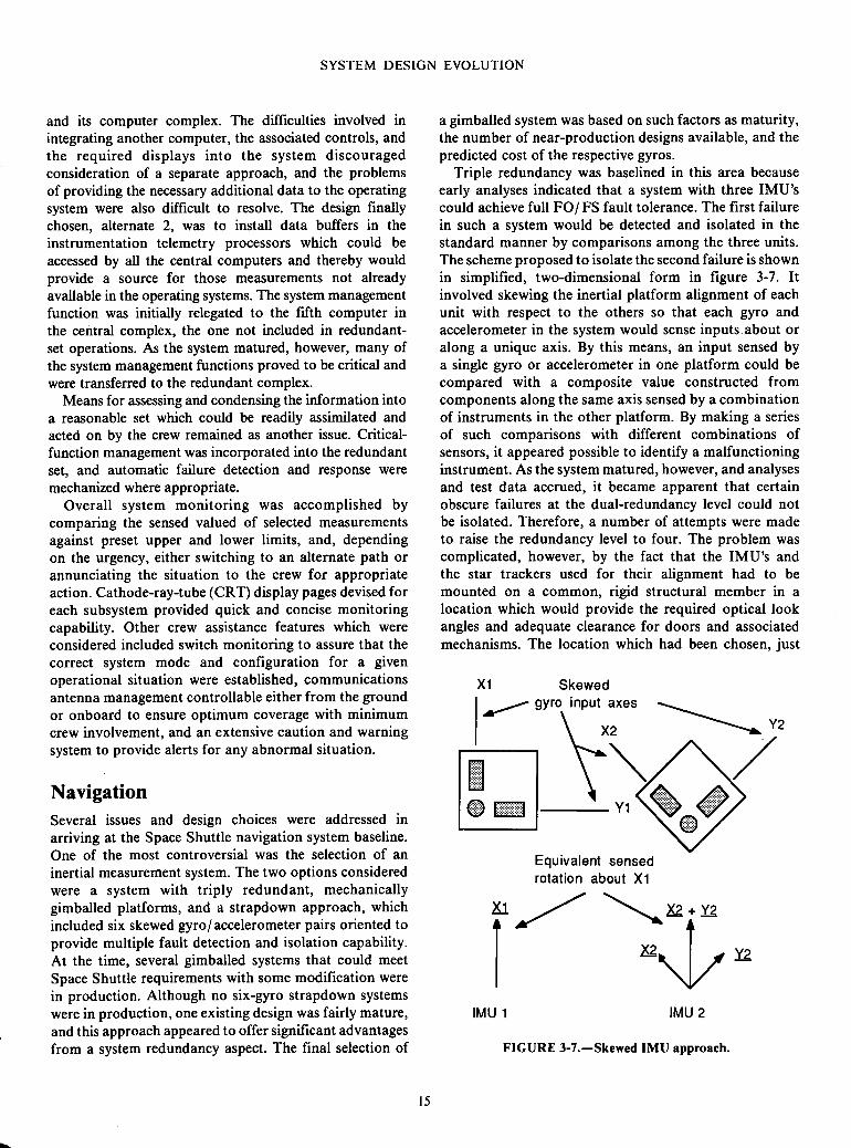
Triple redundancy was baselined in this area because early analyses indicated that a system with three IMU's could achieve full FO/ FS fault tolerance. The first failure in such a system would be detected and isolated in the standard manner by comparisons among the three units. The scheme proposed to isolate the second failure is shown in simplified, two-dimensional form in figure 3-7. It involved skewing the inertial platform alignment of each unit with respect to the others so that each gyro and accelerometer in the system would sense inputs, about or along a unique axis. By this means, an input sensed by a single gyro or accelerometer in one platform could be compared with a composite value constructed from components along the same axis sensed by a combination of instruments in the other platform. By making a series of such comparisons with different combinations of sensors, it appeared possible to identify a malfunctioning instrument. As the system matured, however, and analyses and test data accrued, it became apparent that certain obscure failures at the dual-redundancy level could not be isolated. Therefore, a number of attempts were made to raise the redundancy level to four. The problem was complicated, however, by the fact that the IMU's and the star trackers used for their alignment had to be mounted on a common, rigid structural member in a location which would provide the required optical look angles and adequate clearance for doors and associated mechanisms. The location which had been chosen, just
Equivalent sensed rotation about Xl
4r________•X2+2
X2
111^/ Y-2
IMU1 IMU2
FIGURE 3-7.—Skewed IMU approach.
15

SPACE SHUTTLE AVIONICS SYSTEM
forward of the cockpit with the star tracker door openings in the upper left area of the fuselage, was optimum but unfortunately did not contain enough volume to accommodate a fourth unit of the size then available. One alternate location, on the upper corners of the forward payload bay bulkhead, was briefly examined but discarded because of alignment problems and the difficulty in providing an adequate structural mount. Another alternative, in which an additional IMU would have been mounted inverted under the existing structure, would have forced the relocation of other equipment with excessive cost. Therefore, the decision was made to keep the triply redundant baseline but to make every attempt to reduce the probability of exposure to a second failure to an acceptable level. One measure taken was to exploit the use of IMU BITE to the maximum. This measure alone provided the capability to detect as many as 90 percent of all failures. Another technique, used during entry, was to integrate rate gyro outputs to provide an additional attitude reference. The result, when considered in terms of the relatively short periods of exposure during ascent and entry and of the remote possibility that a second failure would be of the precise type which would escape detection, was considered to be a safe and satisfactory system.
The selection of an on-orbit navigation system also proved to be a difficult process especially in view of the Orbiter autonomy requirement. No operational sensor or system which could meet accuracy, coverage, and autonomy requirements was available. The Department of Defense (DOD) Global Positioning System (GPS) was only in the initial phase of development, and no assurance could then be given that the project would be completed. Several other concepts were investigated, including one called the precision ranging system (PRS), which would have used onboard distance measuring devices operating with a network of transponders distributed on the ground at strategic locations around the world and in the vicinity of the landing sites. Several studies conducted showed that, given the required number and locations of transponders, a PRS could easily meet all Space Shuttle navigation accuracy requirements. To adopt such a system, however, meant that NASA would have to install and maintain the dedicated worldwide network.
In another concept, the RF emissions from ground-based radars located around the world would have been tracked to obtain angular data from which a state vector could have been constructed. This system also had promise but would have required the development of onboard electronics equipment which was extremely sophisticated for the time. The technique finally chosen was to make the ground-Orbiter-ground communications link coherent and thereby to provide the capability to precisely measure the Doppler shift in the carrier frequency and to obtain
an accurate time history of relative range rate between the spacecraft and a ground station. From this informa-tion, the vehicle state vector could be constructed. The system was originally mechanized so that the Doppler information could be extracted both on the ground and onboard. Later in the program, the ground was made prime for on-orbit navigation and the onboard capability was deleted. The realization of autonomous on-orbit navigation was left to the GPS.
The issues involved with rendezvous navigation concerned both performance and mechanization. No definitive rendezvous targets or their characteristics existed; therefore, radar performance requirements were difficult to specify. Finally, after much debate, it was decided that the capability should be provided to acquire range and angle data from both cooperative and uncooperative targets and that the performance should be that reasonably available from state-of-the-art solid-state devices. The mechanization finally chosen was to incorporate the radar in the Ku-band communications system, which required a high-gain directable antenna and other components which could service both radar and communications functions.
The system selected to provide navigation for the postblackout entry phase was the DOD tactical air navigation system network. This choice was made only after much deliberation because tacan performance was neither documented nor specified above 12.2 to 15.2
kilometers (40 000 to 50 000 feet) and the Space Shuttle requirement extended to an altitude of approximately 42.7 kilometers (140 000 feet). Analytic performance predic-tions and laboratory test results indicated that perform-ance would be satisfactory, however, and three off-the-shelf transceivers, modified as necessary to interface with the onboard data processing system, were baselined. Triple redundancy was considered adequate because of the short period of exposure and because the ground could provide some assistance if two failures occurred.
The predominant navigation aids in place at the time for the final approach and landing phase were the FAA ILS and the USAF ground-controlled approach (GCA) system; however, both the performance and the coverage provided by these systems were deemed inadequate for the type of approach to be flown by the Space Shuttle. The FAA was considering an upgrade to a precision microwave landing system, but no firm schedule existed. Precision microwave systems also under development by DOD would meet Space Shuttle performance and coverage requirements, and a variation of one of these was chosen, again modified to interface with the DPS. Triple redundancy was considered sufficient for this system also, both because of the short exposure and because the pilot could take over visually under most expected conditions.
FE1

SYSTEM DESIGN EVOLUTION
Display and Control The major challenge facing the designers of the Space Shuttle cockpit was to integrate all the controls and displays required for operation of the vehicle and its subsystems into the space available, within the reach and vision of the crew as appropriate for each mission phase. Some of the basic requirements imposed were
• Safe return with a single crewman from either forward station
• Normal operation, except payload management, with a crew of two
• Accessibility from the two forward stations of all controls and displays required for ascent and entry
• Provisions for manual override of automated critical functions
• Crew selection of automatic or manual flight guidance and control
• Means to annunciate faults in and to command safing of hazardous systems
In addition, the system would have to provide for both space flight and aircraft aerodynamic flight, a first in the manned space program. In the early design phases, the controls required for these two flight modes were thought to be so incompatible that consideration was given to incorporating two separate cockpits, one exclusively devoted to and equipped for aerodynamic flight, the other for space operations. The program could not afford the cost, complexity, and inefficiency of such an approach, however, and a single, integrated, two-man forward control station was baselined for both regimes. The aft portion of the upper cockpit, because of visibility advantages looking up, aft, and into the payload bay area, was equipped with controls and displays sufficient for on-orbit proximity and payload operations. Despite the integrated approach, however, dedication of some devices to one or the other flight regime could not be avoided. The preferred pilot input devices for aerodynamic flight were a traditional control stick (or yoke/wheel) and rudder pedals. For space flight, three-axis hand controllers for attitude and translation control were desired. After much deliberation and many simulations, the decision was made to adopt a variation of a side-arm controller which would provide pitch and roll input capability in the aircraft mode and pitch, roll, and yaw inputs in the spacecraft mode. These devices were located in the standard aircraft position between the pilot's and copilot's legs, situated to provide clearance for ejection, a capability included on early flights. Rudder/ brake pedals, active only in the aerodynamic mode, were included to provide yaw inputs and to apply the wheel brakes. Other devices
dedicated to aerodynamic flight included the speed brake and body flap controls. A three-axis translation controller was included to provide on-orbit maneuver capability. Most displays served a dual or universal purpose; however, some, such as air data, the radar altimeter, and those associated with navigation aids, became active only after blackout.
The display and control concepts proposed very early in the program included extensive use of multifunction CRT's, reformattable control panels, multipurpose keyboards, head-up displays, and limited use of dedicated switches and circuit breakers. The technology involved was then at the leading edge of the state of the art for aerospace systems, however, and, because it appeared that more conventional approaches would suffice, the decision was made to use off-the-shelf equipment wherever possible. The system which evolved, therefore, contains an extremely large number and variety of components. Control devices include toggle, pushbutton, thumbwheel, and rotary switches; potentiometers; keyboards; circuit breakers; and hand controllers. Displays include circular and vertical meters, tape meters, mechanical talkbacks, annunciators, flight control meters, electromechanical position and attitude indicators, digital readouts, and CRT's. The four CRT's in the final design incorporate multifunctionality but to a much smaller degree than those in the original concepts.
Communications The Space Shuttle communications design community was faced with a variety of requirements, many conflicting, and many unique to or faced for the first time in the Space Shuttle Program. The network communications system had to accommodate voice, command, and data traffic with the NASA Ground Spaceflight Tracking and Data Network (GSTDN), with the USAF Space Ground Link System (SGLS), and with NASA Tracking and Data Relay Satellites (TDRS's) in geosynchronous orbit. The downlink data to be accommodated ranged from real-time operational telemetry to television to wide-band payload/ experiment data. Because the Orbiter would operate as an aircraft in atmospheric flight, the system would have to provide for air traffic control (ATC) type interfaces from postblackout through landing. Also because of the operation in the atmosphere, all antennas had to be either flush-mounted under the thermal protection system or deployable on orbit and retractable for ascent and entry. Other factors which influenced the design included requirements for communications security, all-attitude operation, coherent Doppler for navigation, voice and data links to an extravehicular astronaut, text and graphics uplink, active and passive tracking of satellites for rendezvous, and extensive remote
17

SPACE SHUTTLE AVIONICS SYSTEM
control capability from the ground to reduce crew workload. In addition, the always overriding requirements to minimize weight, power, volume, and complexity and to use off-the-shelf equipment were present and contributed to the system configuration.
The GSTDN and SGLS networks both operate at S-band frequencies with direct ground/ spacecraft/ ground link performance requirements similar to those encoun-tered on previous low Earth orbit missions. The TDRS operates at both S-band and Ku-band frequencies but with much more stringent link performance requirements because of the distances, look angles, and dynamics involved in operations with a synchronous orbit communications terminal. Off-the-shelf S-band trans-ponders which would have allowed operation with either ground network were available, but none could meet the TDRS link margin requirements. Because the requirement existed for communications coverage during ascent, on-orbit, and entry phases when out of sight of ground stations and operating with the flush-mounted, low-gain antennas, the decision was made to develop new S-band hardware which would provide for basic operational voice/command/telemetry traffic through either ground network or the TDRS using an integrated onboard system.
The basic Space Shuttle operational network commu-nications requirement called for voice channels (up and down), an uplink command channel, a telemetry downlink channel, two-way coherent Doppler for ground naviga-tion, a ground ranging capability, and provisions for communications security. The stringent TDRS link performance requirements, exacerbated by the low-gain antennas, drove the system to an all-digital signal design using time-division multiplexing (TDM) to integrate the voice and command or data channels into a common bit stream. An adaptive delta modulation technique using a modified version of the ABATE algorithm was chosen to digitize the voice channels after extensive in-house laboratory tests showed that this method maintained high word intelligibility with reasonable voice quality at minimum sampling rates in the presence of very high channel errors. To achieve optimum performance on these digital channels, a phase modulation (PM) system was developed which included one or two voice channels multiplexed with an encoded 8-kbps command channel on the uplink or with a 128- or 64-kbps pulse code modulated (PCM) telemetry bit stream on the downlink. To maintain adequate circuit margins and bit error rates at these data rates for the Space Shuttle/TDRS link, it proved necessary to develop a 100-watt traveling wave tube power amplifier transmitter and a low-noise preamplifier receiver, both of which pushed the state of the art, and to employ sophisticated error-correcting channel-encoding techniques. After a series of tradeoff studies, convolutional encoding and Viterbi decoding were
selected to optimize the link. Phase-shift keying (PSK) was also selected to optimize channel performance with a Costas loop to provide for carrier reconstruction and data recovery on both forward and return link signals. To provide accurate Doppler data which would allow the ground control center to determine and maintain the Space Shuttle ephemeris, the S-band uplink and downlink signals were made coherent. Range tone turnaround was incorporated to provide a direct ranging capability at GSTDN stations for ascent and postblackout entry state vector determination. An additional constraint on the system was imposed by international agreements which specify the maximum allowable power flux density received at the Earth's surface from an orbiting satellite. To avoid exceeding this limit on the TDRS to Orbiter link, it proved necessary to develop a direct-sequence spread-spectrum signal design using pseudorandom noise (PN) code modulation.
The Space Shuttle/ground direct S-band link was also required to accommodate wide-band telemetry data from the main engines during ascent, data dumps from onboard recorders, payload data (analog data up to 4 megahertz, digital data up to 5 Mbps), and video from the onboard television system. Because these types of data were not amenable to incorporation into the limited-rate PCM telemetry data stream described previously, a separate S-band system was developed for this purpose using frequency modulation (FM) and an independent signal processor, transmitter, and antennas.
Initially, the communications and data requirements of the payload community were either unknown or appeared totally open ended. A major mission of the Space Shuttle was to service, deploy, or retrieve a wide, and largely unknown and unpredictable, variety of satellites. Therefore, it posed a major engineering challenge to develop a communications system with some chance of longevity which could generate commands having payload-compatible formats, data rates, and carrier frequencies; monitor telemetry signals having various standard formats, data rates, and subcarrier and carrier frequencies; and relay nonstandard telemetry to the ground without onboard subearrier demodulation and bit synchronization. A series of meetings was held in the early seventies with various involved government and commer-cial organizations in an attempt to develop a real and manageable set of requirements. This activity culminated in a major conference in 1974 at which all prospective payload developers were invited to make suggestions as to how the Space Shuttle could best serve their needs for command and data rates, formats, modulation schemes, and carrier and subcarrier frequencies. It soon became apparent that, to satisfy the entire community, the Space Shuttle would have to provide all the functions and capabilities of all the satellite ground stations and
18

SYSTEM DESIGN EVOLUTION
support networks developed to that time. Although technically feasible, the provision of an essentially open-ended service would have been prohibitively expensive; therefore, the decision was made to provide only normal baseband signal processing functions for a limited number of modulation schemes, subcarriers, bit rates, and PCM formats; and to implement a wide-band, transparent-throughput, indirect-transmission (bent pipe) capability to relay "nonstandard" payload signals through the TDRS Ku-band link for ground monitoring and analysis.
The. requirement for wide-band (50 Mbps) Ku-band data transmission through the TDRS dictated the use of a high-gain deployable antenna with tracking capability over a wide angular range. Early in the design phase, it became apparent that this antenna, its control elements, and major portions of the associated communications hardware could also serve the Orbiter-to-satellite radar tracking requirement with significant savings in weight for the inconvenience of having to interrupt wide-band TDRS communications when performing the radar function. This concept was baselined and the combined Ku-band radar/ communications system design which evolved included an antenna assembly, an antenna controller, a transmitter, a receiver, and associated microwave components common to both functions.
USAF Requirements The U.S. Air Force requirements which influenced the Space Shuttle avionics system design or which raised significant design issues included the following: autonomy, radiation hardening, and communications and data security. The autonomy requirement was defined to be the capability to conduct mission operations without dependence on ground support systems dedicated only to the Space Shuttle. As indicated in previous sections, the avionics design which evolved included provisions for onboard management of vehicle systems, and, except for the lack of an orbital navigation capability, mission operations could be conducted as desired. Incorporation of an autonomous navigation capability was deferred pending the development of the DOD GPS.
The radiation hardening requirement proved to be extremely difficult to quantify in terms of a reasonable threat and even more difficult to meet without a prohibitive weight penalty. The result was a program decision to accept the degree of hardening provided by the shielding and other measures which were incorporated to protect against lightning strikes.
The communications and data security requirements included transmission and reception of encrypted information over the various RF links; processing, storing, and general handling of classified, unencrypted data onboard the spacecraft; and denial of unfriendly access
or control while conducting classified mission operations. (Hereafter, unclassified or encrypted data are defined as "black"; classified, unencrypted data are called "red." Because classified military and unclassified civilian missions were to be interspersed, means had to be provided to purge the spacecraft of any residual red data. In addition, imposition of the Air Force Tempest Specifi-cation for prevention of compromise of classified information through spurious radiation placed unique requirements on the system design.
Several alternatives were considered, ranging from a system which integrated all USAF requirements into the basic Orbiter avionics system to one which created a red/ black data barrier between the Orbiter avionics and an essentially independent USAF system. The system baseline that evolved was a hybrid of these extremes which incorporated many of the basic requirements in the Orbiter system but segregated the unique requirements behind a red/black barrier. The transmission/ reception requirements were met, as indicated in the Communi-cations section, by incorporating encryption/ decryption devices in the communications system and by providing for the necessary authentication protocol. Power, data interfaces, and associated wiring were provided between the Orbiter system and an area in the mission specialist station in which processors, controls, displays, etc., unique to a USAF mission could be installed. Wiring dedicated to this area was subject to the full Tempest requirement. The rest of the Orbiter wiring was required to meet only the normal manned-space-flight standards for electromag-netic interference, etc. Special inhibit switches and procedures were installed and used to preclude any possibility of hostile takeover or access to classified information. Procedures and the necessary associated software were incorporated to purge memories, recorders, and other portions of the system which could possibly retain red data.
Payload Support Because the primary purpose of the Space Shuttle is to deliver, recover, and otherwise service a wide variety of payloads, high priority was given early in the program to incorporating features in the avionics system which would support such operations. As indicated in the Data Processing section, one of the five computers in the data processing complex was originally designated for payload support. Even though this machine eventually became the residence of the backup system during ascent and entry, some payload servicing functions were retained. On orbit, where the redundant set was not required and only one or two of the machines were needed for Orbiter operations, the excess computational capacity was to be made available for payload use. The payload major
19
SPACE SHUTTLE AVIONICS SYSTEM
function, one of the three major software partitions, was created to assemble all payload support programs. The intent was to store these programs in mass memory and to load them as appropriate into one of the unused computers during the on-orbit phase. Two data buses and two multiplexer/demultiplexers (MDM's) were allocated to payload services. A version of the MDM called a "flex MDM," which could easily be reconfigured, was developed especially to accommodate the unique interface requirements of various payloads.
For various reasons, these system features incorporated for payload support have not yet been fully exploited. The difficulty in deriving or distilling a reasonable set of support requirements from the payload community was discussed in the Communications section. In addition, the rigor required and the cost and lead time involved in developing and verifying flight software have discouraged any extensive tailoring of programs to specific payloads. A standard set of services, largely associated with the system management function, has evolved and is provided on each flight. These include caution and warning, limit sensing and status determination, sequencing, and command and telemetry formatting. The GNC function provides pointing information and state vector data as required.
Remote Manipulator Early in the program, the decision was made to provide for control and monitoring of the remote manipulator in the Orbiter avionics system. This device, an 18.3-meter (60 foot) arm with shoulder, elbow, and wrist joints, is designed to insert, remove, and otherwise physically manipulate payloads as heavy as 27 216 kilograms (60 000 pounds) in and about the payload bay. Because of weight constraints, the arm/joint design which evolved is a very slow moving system with rigid arm segments and joints which can be easily back-driven under load. The integrated control dynamics of the combined Orbiter/ loaded arm system, particularly the interaction between the vehicle control system and that of the manipulator, are extremely complex and presented a significant design problem. At issue was the degree of integration of the two control systems. The approaches considered ranged from a single, integrated concept to separate independent systems, with or without crosstalk. After much deliber-ation, the decision was made to make the control systems
and associated software for the Orbiter and manipulator independent and to rely on preflight simulations and operational procedures to avoid possible adverse interactions.
Another issue was the question of collision avoidance. It was possible for the arm, with or without an attached payload, to be commanded to a position which could impact and potentially damage the Orbiter; therefore, a requirement to provide collision detection and prevention measures in the software was originally imposed. Protection against all the possible combinations of arm position and payload geometry proved to be very difficult to mechanize without an unacceptable software penalty, and the requirement eventually evolved to one which called for software reasonableness tests to ascertain that no command inconsistent with the crew inputs was being transmitted.
Power Distribution The size and complexity of the Space Shuttle vehicle forced a number of changes in the approach to power distribution and control followed on previous space programs. As an example, a single-point ground standard, if imposed in the dc distribution system, would have resulted in a 2268-kilogram (5000 pound) weight penalty and, therefore, had to be relaxed. A multipoint system with structure return was used; however, isolation was maintained between primary power returns and LRU chassis and these returns were brought out to controlled points on the fore and aft payload bay bulkheads. Another example is the extensive use of remote power controllers and computer-controlled load switching, employed both to reduce weight and to reduce the crew's workload.
Other issues faced in the power area included the redundancy level of the system and the requirement for battery backup to the fuel cells. A three-bus distribution system was selected on the basis of both weight and reliability considerations. The battery issue was also resolved on the basis of weight and reliability. Even the minimum loads required for safe return would have required a prohibitively heavy battery complex. The system which evolved was two-fault tolerant, with extensive cross-tie capability and multiple feeds to critical LRU's to enhance failure tolerance and to protect against transients.
20
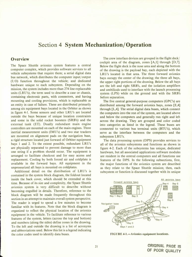
Section 4 System Mechanization/ Operation
Overview The Space Shuttle avionics system features a central computer complex, which provides software services to all vehicle subsystems that require them; a serial digital data bus network, which distributes the computer input/output (I/O) function throughout the vehicle; and dedicated hardware unique to each subsystem. Depending on the mission, the system includes more than 274 line-replaceable units (LRU's), the term used to describe a case or chassis, containing electronic parts, with connectors, and having mounting and cooling provisions, which is replaceable as an entity in case of failure. These are distributed primarily among six equipment bays located in the Orbiter as shown in figure 4-1. Some sensors and other LRU's are located outside the bays because of unique location constraints and some in the solid rocket boosters (S RB's) and the external tank (ET). Dually redundant main engine controllers are mounted on each of the main engines. Three inertial measurement units (IMU's) and two star trackers are mounted on alignment pads on the navigation base, a rigid structure located just forward of Orbiter equipment bays I and 2. To the extent possible, redundant LRU's are physically separated to prevent damage to more than one string if a problem should occur. The equipment is arranged to facilitate checkout and for easy access and replacement. Cooling by both forced air and coldplate is available in the forward bays. All equipment in the unpressurized aft bays is mounted on coldplates.
Additional detail on the distribution of LRU's is contained in the system block diagram, the foldout located inside the back cover, which should be extended at this time. Because of its size and complexity, the Space Shuttle avionics system is very difficult to describe without becoming engulfed in details. Therefore, reference to the block diagram will be made frequently throughout this section in an attempt to maintain overall system perspective. The reader is urged to spend a few minutes to become familiar with its features. Note that the block diagram is organized to reflect the physical location of the avionics equipment in the vehicle. To facilitate reference to various features of the system, letters (across the top and bottom) and numbers (along the sides) define zones in the drawing. To the left and outside the drawing is a list of acronyms and abbreviations used. Below this list is a legend indicating the color codes used to identify data buses.
The crew interface devices are grouped in the flight deck/ cockpit area of the diagram, zones [A,l] through [D,7]. Below the flight deck is the nose area and along the bottom of the drawing is the payload bay, each depicted with the LRU's located in that area. The three forward avionics bays occupy the center of the drawing; the three aft bays, the upper right portions of the drawing. Below the aft bays are the left and right SRB's, and the isolation amplifiers and umbilicals used to interface with the launch processing system (LPS) while on the ground and with the SRB's before separation.
The five central general-purpose computers (GPC's) are distributed among the forward avionics bays, zones [E,4] through [L,4]. The serial digital data buses, which connect the computers into the rest of the system, are located above and below the computers and generally run right and left across the drawing. They are grouped and color coded into categories as listed in the legend. These buses are connected to various bus terminal units (BTU's), which serve as the interface between the computers and the subsystem LRU's.
The data processing system (DPS) provides services to all of the avionics subsystems and functions as shown in figure 4-2. Each of the subsystems has unique, dedicated hardware, but all associated applications software modules are resident in the central computers and all functions use features of the DPS. In the following subsections, first, the major functions of the avionics system are described as they relate to the Space Shuttle mission; then, each subsystem or function is discussed together with its unique
Aft avionics bays Forward avionics bays
Bay 4 Bay 5
Bay 1 Bay 2 Bay 3
Bay 5Bay 6
Navigation base
MM
Bay 4
Bay 6
"Bay 3
1 and 2
FIGURE 4-1.—Avionics equipment locations.
21 ORIGINAL PAGE Is OF POOR QUALITY
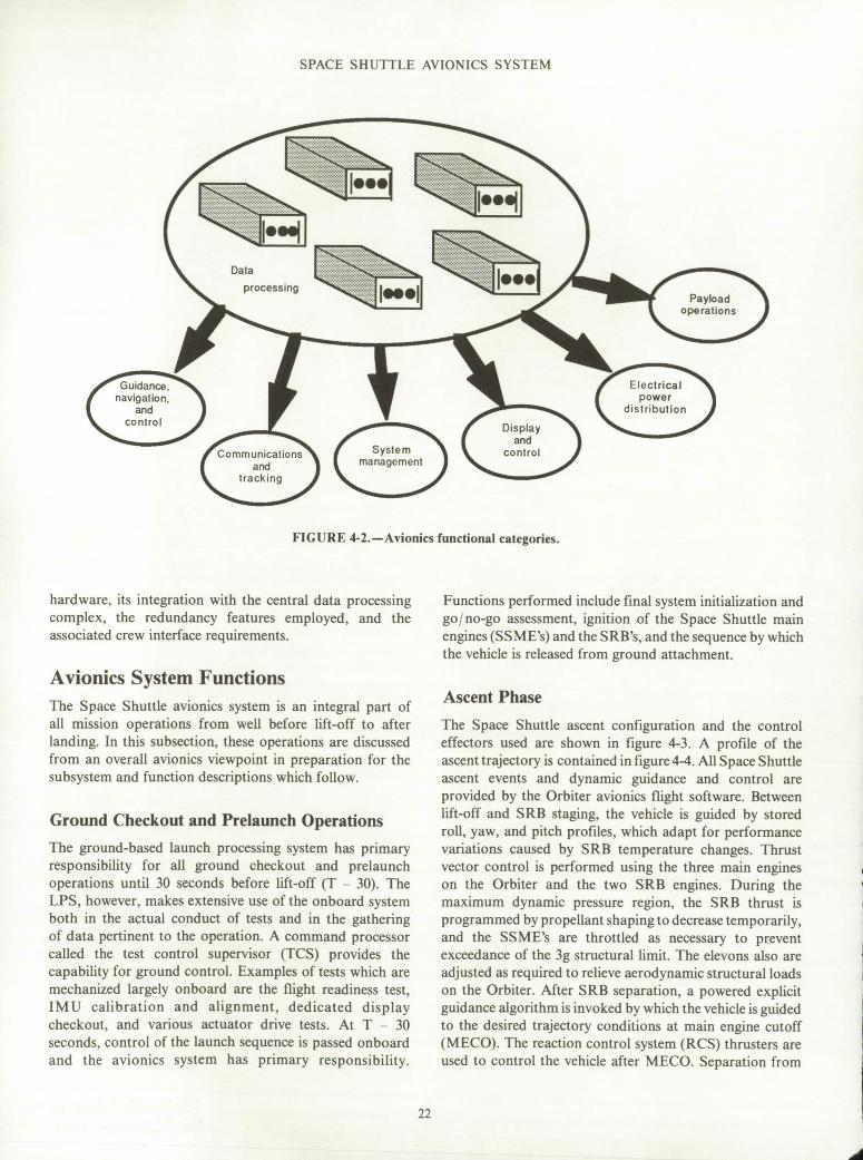
SPACE SHUTTLE AVIONICS SYSTEM
Payload operations
Electrical power
distribution Dand
System ( and Cornmurnc:tions management
controt and
FIGURE 4-2.—Avionics functional categories.
hardware, its integration with the central data processing complex, the redundancy features employed, and the associated crew interface requirements.
Avionics System Functions The Space Shuttle avionics system is an integral part of all mission operations from well before lift-off to after landing. In this subsection, these operations are discussed from an overall avionics viewpoint in preparation for the subsystem and function descriptions which follow.
Ground Checkout and Prelaunch Operations
The ground-based launch processing system has primary responsibility for all ground checkout and prelaunch operations until 30 seconds before lift-off (T - 30). The LPS, however, makes extensive use of the onboard system both in the actual conduct of tests and in the gathering of data pertinent to the operation. A command processor called the test control supervisor (TCS) provides the capability for ground control. Examples of tests which are mechanized largely onboard are the flight readiness test, IMU calibration and alignment, dedicated display checkout, and various actuator drive tests. At T - 30 seconds, control of the launch sequence is passed onboard and the avionics system has primary responsibility.
Functions performed include final system initialization and go/no-go assessment, ignition of the Space Shuttle main engines (SSME's) and the SRB's, and the sequence by which the vehicle is released from ground attachment.
Ascent Phase
The Space Shuttle ascent configuration and the control effectors used are shown in figure 4-3. A profile of the ascent trajectory is contained in figure 44. All Space Shuttle ascent events and dynamic guidance and control are provided by the Orbiter avionics flight software. Between lift-off and SRB staging, the vehicle is guided by stored roll, yaw, and pitch profiles, which adapt for performance variations caused by SRB temperature changes. Thrust vector control is performed using the three main engines on the Orbiter and the two SRB engines. During the maximum dynamic pressure region, the SRB thrust is programmed by propellant shaping to decrease temporarily, and the SSME's are throttled as necessary to prevent exceedance of the 3g structural limit. The elevons also are adjusted as required to relieve aerodynamic structural loads on the Orbiter. After SRB separation, a powered explicit guidance algorithm is invoked by which the vehicle is guided to the desired trajectory conditions at main engine cutoff (MECO). The reaction control system (RCS) thrusters are used to control the vehicle after MECO. Separation from
22
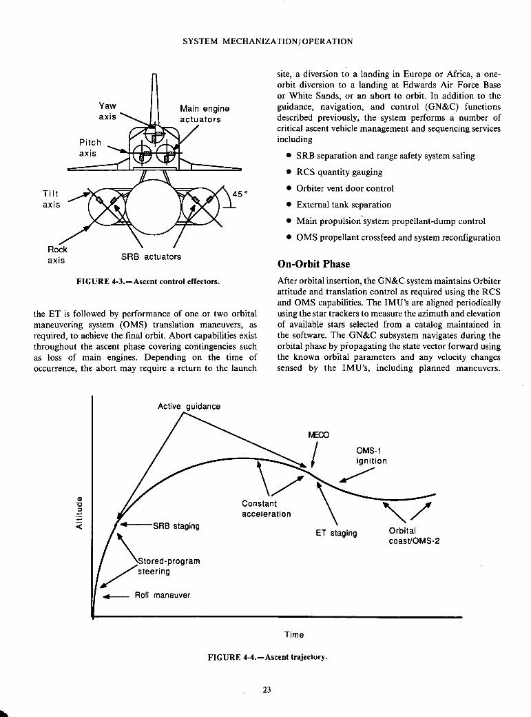
Tilt axi
Rot axis SRB actuators
E
\ Constant acceleration
/ignition
\ ET staging Orbital
coast/OMS-2 SRB staging
\stored-program steering
Roll maneuver
SYSTEM MECHANIZATION/ OPERATION
FIGURE 4-3.—Ascent control effectors.
the ET is followed by performance of one or two orbital maneuvering system (OMS) translation maneuvers, as required, to achieve the final orbit. Abort capabilities exist throughout the ascent phase covering contingencies such as loss of main engines. Depending on the time of occurrence, the abort may require a return to the launch
site, a diversion to a landing in Europe or Africa, a one-orbit diversion to a landing at Edwards Air Force Base or White Sands, or an abort to orbit. In addition to the guidance, navigation, and control (GN&C) functions described previously, the system performs a number of critical ascent vehicle management and sequencing services including
• SRB separation and range safety system safing
• RCS quantity gauging
• Orbiter vent door control
• External tank separation
• Main propulsion system propellant-dump control
• OMS propellant crossfeed and system reconfiguration
On-Orbit Phase
After orbital insertion, the GN&C system maintains Orbiter attitude and translation control as required using the RCS and OMS capabilities. The IMU's are aligned periodically using the star trackers to measure the azimuth and elevation of available stars selected from a catalog maintained in the software. The GN&C subsystem navigates during the orbital phase by propagating the state vector forward using the known orbital parameters and any velocity changes sensed by the IMU's, including planned maneuvers.
Active guidance
Time
FIGURE 4-4.—Ascent trajectory.
23
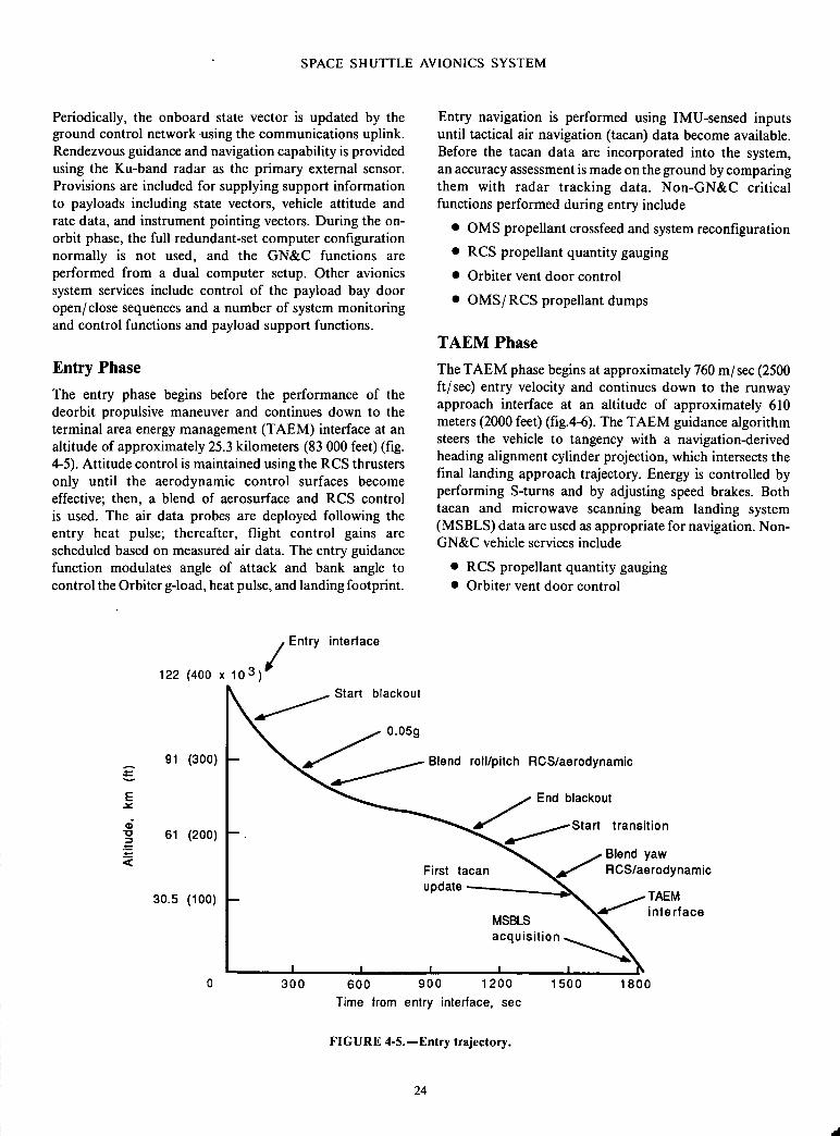
SPACE SHUTTLE AVIONICS SYSTEM
Periodically, the onboard state vector is updated by the ground control network -using the communications uplink. Rendezvous guidance and navigation capability is provided using the Ku-band radar as the primary external sensor. Provisions are included for supplying support information to payloads including state vectors, vehicle attitude and rate data, and instrument pointing vectors. During the on-orbit phase, the full redundant-set computer configuration normally is not used, and the GN&C functions are performed from a dual computer setup. Other avionics system services include control of the payload bay door open/ close sequences and a number of system monitoring and control functions and payload support functions.
Entry Phase
The entry phase begins before the performance of the deorbit propulsive maneuver and continues down to the terminal area energy management (TAEM) interlace at an altitude of approximately 25.3 kilometers (83 000 feet) (fig. 4-5). Attitude control is maintained using the RCS thrusters only until the aerodynamic control surfaces become effective; then, a blend of aerosurface and RCS control is used. The air data probes are deployed following the entry heat pulse; thereafter, flight control gains are scheduled based on measured air data. The entry guidance function modulates angle of attack and bank angle to control the Orbiter g-load, heat pulse, and landing footprint.
/ Entry interface
122 (400 xStart blackout
_. 0.05g
91 (300)
E Je
-g 61 (200)
Entry navigation is performed using IMU-sensed inputs until tactical air navigation (tacan) data become available. Before the tacan data are incorporated into the system, an accuracy assessment is made on the ground by comparing them with radar tracking data. Non-GN&C critical functions performed during entry include
• OMS propellant crossfeed and system reconfiguration
• RCS propellant quantity gauging
• Orbiter vent door control
• OMS/RCS propellant dumps
TAEM Phase
The TAEM phase begins at approximately 760 m/ sec (2500 ft/ sec) entry velocity and continues down to the runway approach interface at an altitude of approximately 610 meters (2000 feet) (fig.4-6). The TAEM guidance algorithm steers the vehicle to tangency with a navigation-derived heading alignment cylinder projection, which intersects the final landing approach trajectory. Energy is controlled by performing S-turns and by adjusting speed brakes. Both tacan and microwave scanning beam landing system (MSBLS) data are used as appropriate for navigation. Non-GN&C vehicle services include
• RCS propellant quantity gauging • Orbiter vent door control
Blend roll/pitch RCS/aerodynamic
End blackout
Start transition
300 600
Blend yaw First tan ca RCS/aerodynamic
TAEM update
MSBLS interface
acquisition
900 1200 1500 1800
30.5 (100)
Time from entry interface, sec
FIGURE 4-5.—Entry trajectory.
24

SYSTEM MECHANIZATION! OPERATION
Prellare
Runway
AcquisitionHeading alignment cylinder
(>Sturns TAEM interface (25.3 km (83 000 It))
FIGURE 4-6.—Terminal area energy management.
Approach and Landing Phase
The final approach trajectory is shown in figure 4-7. The MSBLS and the IMU's serve as the navigation sensors. Below an altitude of 1524 meters (5000 feet), radar altimeter data are displayed for monitoring purposes. Although full autoland capability is available, the normal procedure is for the crew to assume manual control before the flare maneuver leading to the shallow glideslope. When in manual mode, the system continues to compute and display steering commands to the desired flightpath. A heads-up display (HUD) is used to superimpose trajectory monitoring and dynamic flight data on the out-the-window view. Non-GN&C vehicle services include
• RCS propellant quantity gauging
• Orbiter vent door control
• Landing gear isolation valve control
General Mission Functions
In addition to the mission-phase-oriented functions described previously, a number of services which apply throughout the mission are performed by the avionics system. The instrumentation subsystem gathers data from all vehicle systems to be used by the onboard system management and caution and warning functions and/or to be telemetered to the ground support network for monitoring and performance evaluation. The communica-tions subsystem provides a number of services including two-way space/ground voice and data links, television, intercom, and extravehicular and payload links. These services are discussed in the Communications and Tracking section. The avionics system also provides distribution and control of electrical power for all vehicle systems.
Data Processing The data processing complex includes the following key features:
• Five GPC's mechanized in a parallel-redundant digital computation system
• Software programs combined in individual memory loads which provide all required subsystem, vehicle, and mission services
• Multiplexed data transmission with standardized subsystem interfaces
• Distributed I/O through remotely located multi-plexer/demultiplexer (MDM) units
• Multifunctional cathode-ray-tube (CRT) displays/ keyboards
• Mass program storage in two tape memory units
Computer Configuration
The five GPC's are identical IBM AP-10I13 machines. Each GPC is packaged in two boxes, one containing the central processing unit (CPU) and part of the memory (80k 32-bit words), the other containing the input/ output processor (lOP) and the rest of the memory (24k 32-bit words). A GPC upgrade, to the AP-I01S, is currently under way in the program. This upgrade will combine the CPU and the lOP into one package and increase the memory to 256k. All GPC's are wired alike with both discrete and serial digital I/O provisions. The discretes are used for computer moding, control, synchronization, station identification, and redundancy management. Twenty-four serial digital ports provide the interfaces with the rest of the avionics system. Each port has a bus control element (BCE), which is under software control and which can be individually enabled to transmit and receive on the respective data bus. The transmit/ receive configuration of the ports on each machine is automatically established by the resident
Autoland interface
-20° glideslope
E0 00 0 Touchdown
/
12.8 km lid (6.9 n. mi.)
FIGURE 4-7.—Final approach.
25
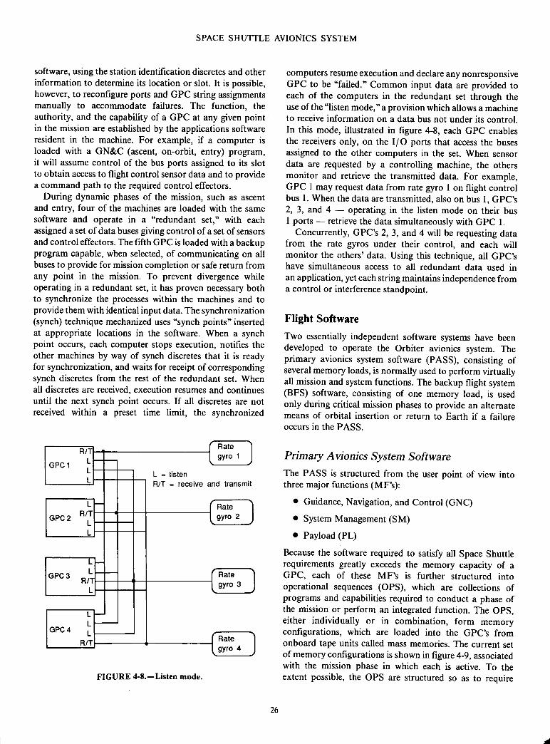
SPACE SHUTTLE AVIONICS SYSTEM
software, using the station identification discretes and other information to determine its location or slot. It is possible, however, to reconfigure ports and GPC string assignments manually to accommodate failures. The function, the authority, and the capability of a GPC at any given point in the mission are established by the applications software resident in the machine. For example, if a computer is loaded with a GN&C (ascent, on-orbit, entry) program, it will assume control of the bus ports assigned to its slot to obtain access to flight control sensor data and to provide a command path to the required control effectors.
During dynamic phases of the mission, such as ascent and entry, four of the machines are loaded with the same software and operate in a "redundant set," with each assigned a set of data buses giving control of a set of sensors and control effectors. The fifth GPC is loaded with a backup program capable, when selected, of communicating on all buses to provide for mission completion or safe return from any point in the mission. To prevent divergence while operating in a redundant set, it has proven necessary both to synchronize the processes within the machines and to provide them with identical input data. The synchronization (synch) technique mechanized uses "synch points" inserted at appropriate locations in the software. When a synch point occurs, each computer stops execution, notifies the other machines by way of synch discretes that it is ready for synchronization, and waits for receipt of corresponding synch discretes from the rest of the redundant set. When all discretes are received, execution resumes and continues until the next synch point occurs. If all discretes are not received within a preset time limit, the synchronized
Rate 7L roi
L = listen R/T = receive and transmit
Rate GPC2 R/Tfl i gyro 2
computers resume execution and declare any nonresponsive GPC to be "failed." Common input data are provided to each of the computers in the redundant set through the use of the "listen mode," a provision which allows a machine to receive information on a data bus not under its control. In this mode, illustrated in figure 4-8, each GPC enables the receivers only, on the I/O ports that access the buses assigned to the other computers in the set. When sensor data are requested by a controlling machine, the others monitor and retrieve the transmitted data. For example, GPC 1 may request data from rate gyro 1 on flight control bus 1. When the data are transmitted, also on bus 1, GPC's 2, 3, and 4 - operating in the listen mode on their bus 1 ports - retrieve the data simultaneously with GPC 1.
Concurrently, GPC's 2, 3, and 4 will be requesting data from the rate gyros under their control, and each will monitor the others' data. Using this technique, all GPC's have simultaneous access to all redundant data used in an application, yet each string maintains independence from a control or interference standpoint.
Flight Software
Two essentially independent software systems have been developed to operate the Orbiter avionics system. The primary avionics system software (PASS), consisting of several memory loads, is normally used to perform virtually all mission and system functions. The backup flight system (BFS) software, consisting of one memory load, is used only during critical mission phases to provide an alternate means of orbital insertion or return to Earth if a failure occurs in the PASS.
Primary Avionics System Software
The PASS is structured from the user point of view into three major functions (MF's):
• Guidance, Navigation, and Control (GNC)
• System Management (SM)
• Payload (PL)
GPC3 R. r Rate j if gyro 3
Because the software required to satisfy all Space Shuttle requirements greatly exceeds the memory capacity of a GPC, each of these MF's is further structured into operational sequences (OPS), which are collections of programs and capabilities required to conduct a phase of the mission or perform an integrated function. The OPS, either individually or in combination, form memory configurations, which are loaded into the GPC's from onboard tape units called mass memories. The current set of memory configurations is shown in figure 4-9, associated with the mission phase in which each is active. To the extent possible, the OPS are structured so as to require
L GPC4 L Rate
gyro 4
FIGURE 4-8.—Listen mode.
26

SYSTEM MECHANIZATION! OPERATION
Memory Preflight Ascent! On-orbit On-orbit On-orbit Mass
configuration checkout aborts G'J&C checkout system Entry memory utility management
OperationalGNG9 GNC1 PL9 sequences GNC6
• Subsystem . Terminal • Guidance, . Entry • Subsystem • Guidance, • Mass checkout launch navigation subsystem monitoring navigation memory
• IMU CAL & count & control checkout • Fault & control alignment . Ascent annunc.
Functions guidance, • P/I bay navigation door OPS & control • Antenna Abort mgmnt guidance, • Payload navigation support & control
Mission phase Ground Ascent On-orbit Entry N/A
FIGURE 4-9.—Memory configurations.
memory overlays only in quiescent, nondynamic periods. The substructure within the OPS consists of major
modes, specialist functions (SPEC's), and display functions (DISP's). Each OPS has one or more major modes, which are further substructured into blocks that segment the processes into steps or sequences. (See fig. 4-10.) The blocks are linked to CRT display pages and, therefore, establish an orderly sequence by which the crew can monitor and control the function. Sequencing from mode/block to mode/ block and internal processing can be initiated by keyboard entry from the crew or, in some cases, can be initiated automatically in response to a specific event or condition detected by the software. The SPEC function, initiated only by keyboard entry, also contains blocks that are linked to CRT pages and that establish and present the valid keyboard entry options available to the crew for controlling the operation or monitoring the process. Major modes accomplish the primary functions within an OPS, whereas SPEC's are used for secondary or background functions. The DISP functions, also initiated by keyboard input, contain no processing other than that necessary to produce the display; and are used only for monitoring data processing results.
The software architecture embodied in each PASS memory configuration is shown in figure 4-11. The application processes which make up the major functions of a given memory load are shown in the lower inner block of the diagram, essentially isolated by the system software. The control segment manages the sequencing of all processing required within an OPS, a major mode, or a SPEC, and defines the associated CRT displays and keyboard entry options. The user interface consists of three primary functions: command input processing, operations
control, and output message processing. User interfaces supported in addition to the keyboards and CRT's include the launch data bus used to communicate with the LPS while on the ground, the network signal processor used to process data and commands received by way of the radiofrequency (RF) communications links, and the intercomputer buses used to communicate between GPC's.
Operational sequence
(OPS)
Major Specialist I Display mode I function turclion
(SPEC) 1 (DISP) 1
Block B lock Blo I
i Block Block I
2 2j
II I
Bloc k Block I N NI I
Major Specialist
kfo
mode functi on function
ck(DISP) N
Block
Display
N 'f=IL^
I
)N
Block
FB=
lock
2
Block lock N N
FIGURE 4-10.—OPS substructure.
27
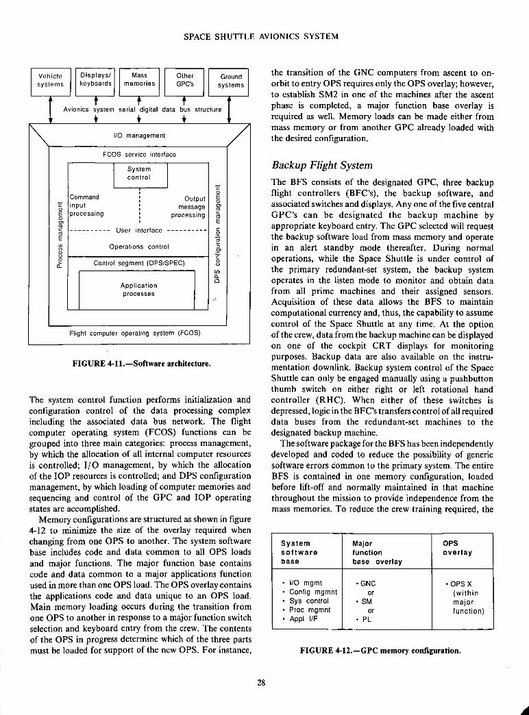
SPACE SHUTTLE AVIONICS SYSTEM
Vehicle I I Displays! I Mass I I Other I Ground systems keyboards
J
memories GPC's J
systems
Avionics system serial digital data bus structure
I/O management
FCOS service interface
I System I control
I
I Command Output I
= a) E wa) input I message CM
E ci)processing I processing I
C c C) I co
cci User interface ---------- .9 E co C,) U, a) 0
Operations control C)
Control segment (OPS/SPEC)C 0 C)
0) I a-I Application
processes
Flight computer operating system (FCOS)
FIGURE 4-11.—Software architecture.
The system control function performs initialization and configuration control of the data processing complex including the associated data bus network. The flight computer operating system (FCOS) functions can be grouped into three main categories: process management, by which the allocation of all internal computer resources is controlled; I/O management, by which the allocation of the lOP resources is controlled; and DPS configuration management, by which loading of computer memories and sequencing and control of the GPC and lOP operating states are accomplished.
Memory configurations are structured as shown in figure 4-12 to minimize the size of the overlay required when changing from one OPS to another. The system software base includes code and data common to all OPS loads and major functions. The major function base contains code and data common to a major applications function used in more than one OPS load. The OPS overlay contains the applications code and data unique to an OPS load. Main memory loading occurs during the transition from one OPS to another in response to a major function switch selection and keyboard entry from the crew. The contents of the OPS in progress determine which of the three parts must be loaded for support of the new OPS. For instance,
the transition of the GNC computers from ascent to on-orbit to entry OPS requires only the OPS overlay; however, to establish SM2 in one of the machines alter the ascent phase is completed, a major function base overlay is required as well. Memory loads can be made either from mass memory or from another GPC already loaded with the desired configuration.
Backup Flight System
The BFS consists of the designated GPC, three backup flight controllers (BFC's), the backup software, and associated switches and displays. Any one of the five central GPC's can be designated the backup machine by appropriate keyboard entry. The GPC selected will request the backup software load from mass memory and operate in an alert standby mode thereafter. During normal operations, while the Space Shuttle is under control of the primary redundant-set system, the backup system operates in the listen mode to monitor and obtain data from all prime machines and their assigned sensors. Acquisition of these data allows the BFS to maintain computational currency and, thus, the capability to assume control of the Space Shuttle at any time. At the option of the crew, data from the backup machine can be displayed on one of the cockpit CRT displays for monitoring purposes. Backup data are also available on the instru-mentation downlink. Backup system control of the Space Shuttle can only be engaged manually using a pushbutton thumb switch on either right or left rotational hand controller (RHC). When either of these switches is depressed, logic in the BFC's transfers control of all required data buses from the redundant-set machines to the designated backup machine.
The software package for the BFS has been independently developed and coded to reduce the possibility of generic software errors common to the primary system. The entire BFS is contained in one memory configuration, loaded before lift-off and normally maintained in that machine throughout the mission to provide independence from the mass memories. To reduce the crew training required, the
System Major OPS software function overlay base base overlay
• I/O mgmt • GNC . OPS X Config mgmnt or (within
• Sys control • SM major • Proc mgmnt or function) • Appi I/F • PL
FIGURE 4-12.—GPC memory configuration.
28

SYSTEM MECHANIZATION! OPERATION
BFS software is organized similarly to the PASS into operational sequences and major modes with SPEC and DISP functions; however, only OPS1 (ascent) and OPS3 (entry) are supported. Although all required guidance, navigation, flight control, sequencing, and system management functions are included, generally, only the simplest mode is mechanized. Limited on-orbit attitude stabilization is provided using the last major mode of OPS 1. The intent is to reload and return to the PASS if a stable orbit has been achieved. The system software uses a synchronous approach and, therefore, is significantly simpler than is the FCOS.
Digital Data Bus System
Twenty-eight data buses connect the GPC complex to BTU's distributed throughout the vehicle. Each data bus has a l-Mbit/sec clock rate, is formatted in Manchester II code, and provides multiple word! message correctness checks. The bus system consists of standard multiplexer interface adapters (MIA's), data bus couplers (DBC's), data bus isolation amplifiers (DBIA's), and twisted, shielded wire pairs. To ensure standardization, performance, and compatibility, the bus elements were purchased from a single manufacturer and MIA's were supplied to all BTU designers for installation in their LRU's. The major bus characteristics are listed in figure 4-13. The system operates in a command/ response mode with all bus control vested in the GPC's. The allowable data bus word configurations are shown in figure 4-14. All bus traffic is initiated by command words transmitted by the GPC's. If the intent
General - 1 Mbps clock rate - Manchester II code format - Multiple word/message Correctness checks
Multiplexer interface adapter (MIA)
- Standardized LRU interface to data bus - Converts NRZ from host to Manchester II - Generates synch bits; assigns parity bits - Checks data validity
Data bus coupler (DBC)
- Signal coupling between bus and LRU - Transformer coupling/isolation - Impedance matching
Data bus isolation amplifier (DBIA)
- In ground support equipment and SFtB interfaces - Amplification for long wire runs - Isolation for guillotined signals
FIGURE 4-13.—Data bus characteristics.
is to transmit data from a computer to a BTU, a command word is sent first as an indicator of a forthcoming data transmission, followed by the required number of data words. To obtain data from a BTU, the computer sends a command word requesting the type and amount of data. The BTU then responds with.the desired number of words. In all cases, the expected word count must be correct or the entire message is rejected. The 28 data buses are allocated by functional use, criticality, and traffic load into categories as shown in table 4-I. The data bus structure interconnecting the GPC's and the various BTU's is shown
Command I Command only word
I Commandi
I Data I I Data I I Data GPC-to-subsystem word word 1 word 2 word N transfer
Subsystem-to-GPC I Command (Command transmitted by GPC) transfer word
I (Data returned from LRU)
Data I I Data I I Data i word 1 word 2 word N
FIGURE 4-14.—Data bus message formats.
29

SPACE SHUTTLE AVIONICS SYSTEM
in figure 4-15, which is a distillation of information contained in the system block diagram. (Again, the reader is urged to maintain correspondence between the figures which are used to emphasize a feature or function of the system and the system block diagram.) The BTU's and their acronyms are listed in the lower left corner of figure 4-15. The attributes of each of these are discussed in sections to follow. The eight flight-critical buses are used for all traffic (data and commands) associated with guidance, navigation, flight control, mission sequences such as separation, and management of critical nonavionics system functions. Also included is the interface with the Space Shuttle main engine controller. Eight buses are required for these critical functions both to provide the necessary fault tolerance and to spread the traffic load. Five buses are devoted to intercomputer data transmission. Each computer acts as the bus controller on one of the five buses and is therefore capable of initiating communications with the other four machines. Two buses interconnect the five computers to the two mass memory units (MMU's). These buses are used for loading of software programs as required throughout the mission. Four buses provide the interface between the five GPC's and the general-purpose CRT display and keyboard equipment. These buses comprise the primary interface between the crew and the DPS. Five
TABLE 4-I.— Data Bus Utilization
No. of buses Function
8 Flight-critical services: guidance and navigation, flight control, sequencing, and main engine interface
5 Intercomputer data transfer 2 Mass memory interface 4 Multifunction display system 5 Pulse code modulation master unit
interface (I dedicated to each GPC) 2 System management and payload OPS 2 Ground interface and remote
manipulator
buses are used for instrumentation data. These buses are unique in that each computer has a dedicated bus connected to a port on dual pulse code modulation (PCM) master units. They are used to transmit downlink data and to acquire data gathered by the operational instrumentation (01) system needed for onboard system management and
Computer 1 Computer 2
o'u CPU
Cpu
2 data buses
Mission llrn
1 data bus
data buses
MaU Mass
memory I
Mass memory 2
IJ central processing unit J display driver unit
EBJ display electronics unit EIU engine Interface unit GPC general-purpose computer UPS launch processing system Of' input/output processor MCIU manipulator controller interface unit MOM multipleser/demultiplexer NEC master events controller Rt pulse code modulation ster
Isolation m p1 ifi era
PCM master t3c* processing
tWsystem -j I MLO2 MDMLRI
MDMOA3 ,OMl.J:u
I I i Solid rocket boosters
MLI3
Instrumentation buses (2)
FIGURE 4-15.—Data bus architecture.
30 ORIGINAL PAGE IS
OF POOR QUALITY
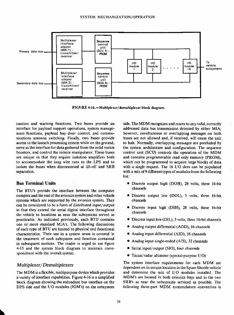
SYSTEM MECHANIZATION/ OPERATION
Prima data bus I
Multiplexer interface adapter (MIA 1) - transmitter/
I I I
I sequence I control I unit I (SCU 1) - I pci I
receiver
I I I
Multiplexer interface
I sequence I control
adapter I I unit Secondary data bus - (MIA 2)
transmitter/(SCU 2) -
PItM i receiver I I
1/0
1/0 /0 To
module module modulevehicle 1 2 is subsystems
FIGURE 4-16.—Multiplexer/demultiplexer block diagram.
caution and warning functions. Two buses provide an interface for payload support operations, system manage-ment functions, payload bay door control, and commu-nications antenna switching. Finally, two buses provide access to the launch processing system while on the ground, serve as the interface for data gathered from the solid rocket boosters, and control the remote manipulator. These buses are unique in that they require isolation amplifiers both to accommodate the long wire runs to the LPS and to isolate the buses when disconnected at lift-off and SRB separation.
Bus Terminal Units
The BTU's provide the interface between the computer complex and the rest of the avionics system and other vehicle systems which are supported by the avionics system. They can be considered to be a form of distributed input/output in that they extend the serial digital interface throughout the vehicle to locations as near the subsystems served as practicable. As indicated previously, each BTU contains one or more standard MIA's. The following discussions of each type of BTU are limited to physical and functional characteristics. Their use in a system sense is covered in the treatment of each subsystem and function contained in subsequent sections. The reader is urged to use figure 4-15 and the system block diagram to maintain corre-spondence with the overall system.
Multiplexer/Demultiplexers The MDM is a flexible, multipurpose device which provides a variety of interface capabilities. Figure 4-16 is a simplified block diagram showing the redundant bus interface on the DPS side and the I/O modules (IOM's) on the subsystem
side. The MDM recognizes and reacts to any valid, correctly addressed data bus transmission detected by either MIA; however, simultaneous or overlapping messages on both buses are not allowed and, if received, will cause the unit. to halt. Normally, overlapping messages are precluded by the system architecture and configuration. The sequence control unit (SCU) controls the operation of the MDM and contains programmable read only memory (PROM), which can be programmed to acquire large blocks of data with a single request. The 16 I/O slots can be populated with a mix of 9 different types of modules from the following list:
• Discrete output high (DOH), 28 volts, three 16-bit channels
• Discrete output low (DOL), 5 volts, three 16-bit channels
• Discrete input high (DIH), 28 volts, three 16-bit channels
• Discrete input low (DIL), 5 volts, three 16-bit channels
• Analog output differential (AOD), 16 channels
• Analog input differential (AID), 16 channels
• Analog input single-ended (AIS), 32 channels
• Serial input/output (S 10), four channels
• Tacan/ radar altimeter (special-purpose I/O)
The system interface requirements for each MDM are dependent on its unique location in the Space Shuttle vehicle and determine the mix of I/O modules installed. The MDM's are located in both avionics bays and in the two SRB's as near the subsystems serviced as possible. The following three-part MDM nomenclature convention is
31
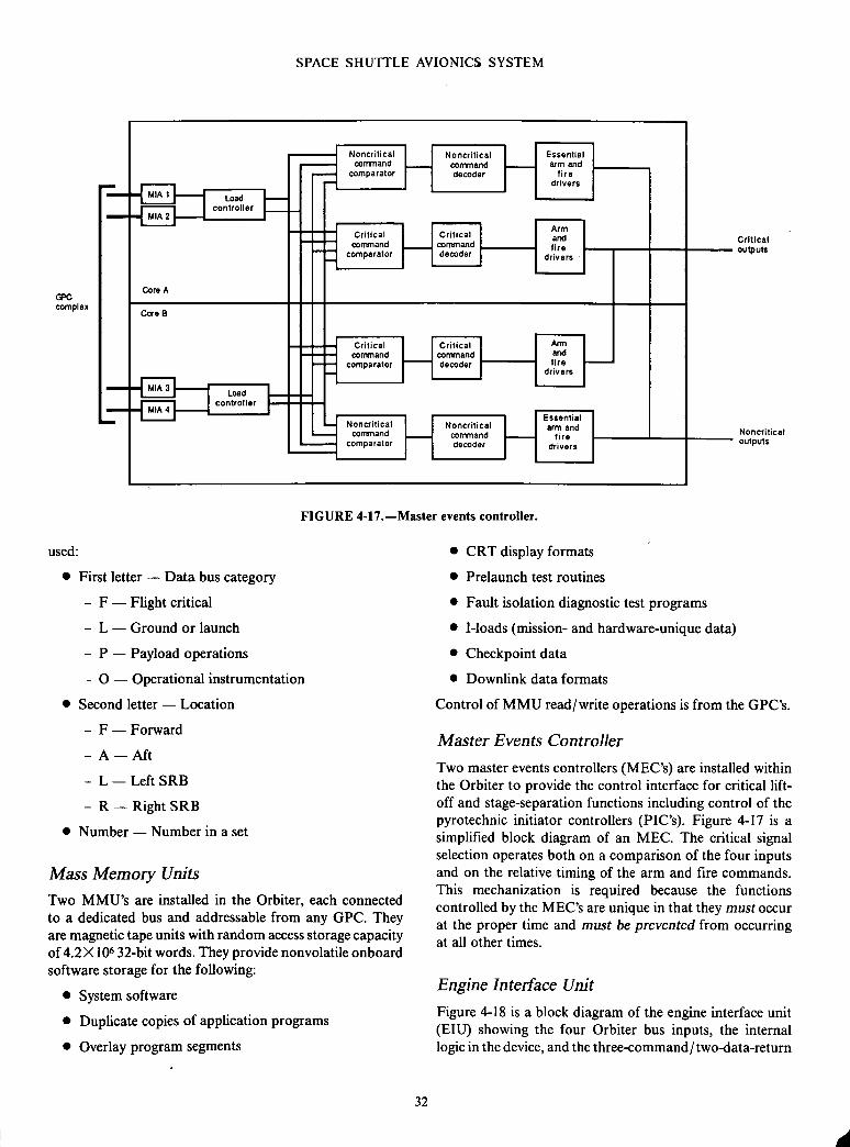
CFC complex
Critical outputs
Noncritical outputs
SPACE SHUTTLE AVIONICS SYSTEM
FIGURE 4-17.—Master events controller.
used: S CRT display formats
• First letter - Data bus category
- F - Flight critical
- L - Ground or launch
- P - Payload operations
- 0 - Operational instrumentation
S Second letter - Location
- F - Forward
- A -Aft
- L - Left SRB
- R - Right SRB
• Number - Number in a set
Mass Memory Units
Two MMU's are installed in the Orbiter, each connected to a dedicated bus and addressable from any GPC. They are magnetic tape units with random access storage capacity of4.2X 106 32-bit words. They provide nonvolatile onboard software storage for the following:
• System software
• Duplicate copies of application programs
S Overlay program segments
• Prelaunch test routines
• Fault isolation diagnostic test programs
• I-loads (mission- and hardware-unique data)
• Checkpoint data
S Downlink data formats
Control of MMU read/ write operations is from the GPC's.
Master Events Controller
Two master events controllers (MEC's) are installed within the Orbiter to provide the control interface for critical lift-off and stage-separation functions including control of the pyrotechnic initiator controllers (PlC's). Figure 4-17 is a simplified block diagram of an MEC. The critical signal selection operates both on a comparison of the four inputs and on the relative timing of the arm and fire commands. This mechanization is required because the functions controlled by the MEC's are unique in that they must occur at the proper time and must be prevented from occurring at all other times.
Engine Interface Unit
Figure 4-18 is a block diagram of the engine interface unit (EIU) showing the four Orbiter bus inputs, the internal logic in the device, and the three-command/ two-data-return
32
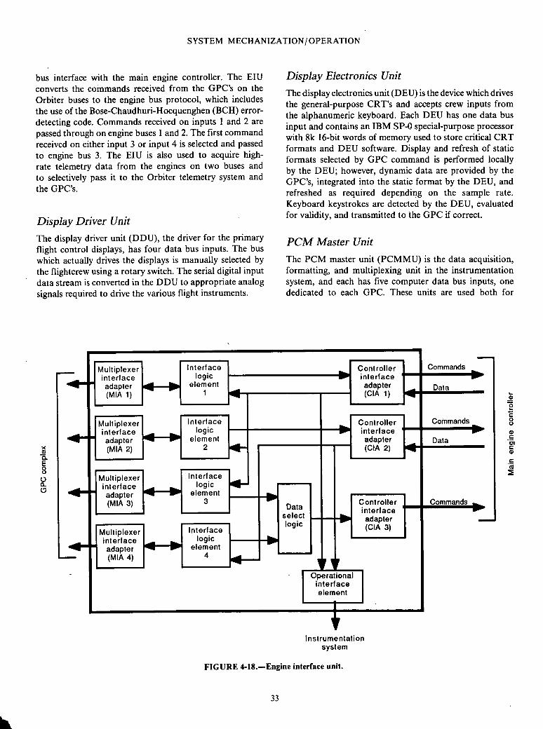
SYSTEM MECHANIZATION! OPERATION
bus interface with the main engine controller. The EIU converts the commands received from the GPC's on the Orbiter buses to the engine bus protocol, which includes the use of the Bose-Chaudhuri-Hocquenghen (BCH) error-detecting code. Commands received on inputs 1 and 2 are passed through on engine buses 1 and 2. The first command received on either input 3 or input 4 is selected and passed to engine bus 3. The EJU is also used to acquire high-rate telemetry data from the engines on two buses and to selectively pass it to the Orbiter telemetry system and the GPC's.
Display Driver Unit The display driver unit (DDU), the driver for the primary flight control displays, has four data bus inputs. The bus which actually drives the displays is manually selected by the flightcrew using a rotary switch. The serial digital input data stream is converted in the DDU to appropriate analog signals required to drive the various flight instruments.
Display Electronics Unit The display electronics unit (DEU) is the device which drives the general-purpose CRT's and accepts crew inputs from the alphanumeric keyboard. Each DEU has one data bus input and contains an IBM SP-0 special-purpose processor with 8k 16-bit words of memory used to store critical CRT formats and DEU software. Display and refresh of static formats selected by GPC command is performed locally by the DEU; however, dynamic data are provided by the GPC's, integrated into the static format by the DEU, and refreshed as required depending on the sample rate. Keyboard keystrokes are detected by the DEU, evaluated for validity, and transmitted to the GPC if correct.
PCM Master Unit
The PCM master unit (PCMMU) is the data acquisition, formatting, and multiplexing unit in the instrumentation system, and each has five computer data bus inputs, one dedicated to each GPC. These units are used both for
- Multiplexer Interface Controller Commands interface logic interface adapter k element adapter I - Data (MIA 1) 1 * (CIA 1)
Multiplexer Interface Controller I Commands interface logic interface I" adapter 40--fill,
Ielement adapter I - Data
X (MIA 2) 2_____________
(CIA 2) _
8_
o I Multiplexer Interface 0_ interface logic ______
adapter ___ element (MIA 3) 3
Data Controller Commands select interface • I L •' adapter
Multiplexer Interface L U interface logic_4J adapter 44-60
I_
element - (MIA 4) 4
[Operationalinterface element
Instrumentation system
FIGURE 4-18.—Engine interface unit.
w 0
0 U a
a C a
Wi

SPACE SHUTTLE AVIONICS SYSTEM
transmission of computer data to be incorporated into the telemetry downlink data stream and for acquisition by the GPC's of instrumentation data for use in system management and caution and warning functions. Each PCMMU also has two instrumentation data bus inputs. These interface with the OF and OA MDM's, which comprise the instrumentation network. The active PCMMU serves as the bus controller on these buses.
Manipulator Controller Interface Unit
The manipulator controller interface unit (MCIU) is the control computer for the remote manipulator system (RMS). It has one data bus port used for receipt of moding and outer loop control signals from the GPC's.
Master Timing Unit
The master timing unit (MTU) is the primary source of time and frequency information for the spacecraft. It is not, by the definition, a BTU because it provides time information through three flight-critical MDM's, but it is described here because of its intimate interface with the data processing complex. The MTU contains two independent 4.608-megahertz crystal oscillators operating in an active/ standby mode. Built-in drift detectors monitor oscillator performance and cause an automatic switchover if an out-of-limits condition occurs. Frequency dividers, counters, and accumulators are included to develop the various outputs required.
DPS Redundancy Management
The DPS, when configured in the redundant set, is designed to operate, when failures are experienced, in a manner so as to require minimal action on the part of the flightcrew. The system will maintain full operation through any single failure with no action whatever. To provide protection against subsequent failures, however, the flightcrew is required to deactivate disabled components as soon as the opportunity arises. Extensive fault detection and annun-ciation capability is provided to the flightcrew on the dedicated displays and on the multifunction CRT's. Each GPC continuously assesses its own functionality and that of the other machines in the redundant set. This assessment produces discrete outputs, which cause lights to be illuminated on the annunciator display unit (ADU) located on the front overhead panel. The ADU contains a five-by five-light matrix with a row and a column designated for each GPC as shown in figure 4-19. Each GPC controls one row of lights—the yellow (Y) is its self-assessment; the white (W) is its assessment of the other machines. The GPC's have extensive built-in test capability and will shut down automatically if failures are detected. No computer
or set of computers can cause another to shut down, however. This action must be taken by the crew, based on an evaluation of the ADU and other system information available.
The architecture of the data bus network also provides failure protection with no immediate response required by the crew. Figure 4-20 contains a view of this architecture which illustrates the multiple interconnectability of the computers and the BTU's. In this figure, the computer ports are shown configured for a nominal ascent mission phase with GPC 5 selected as the backup computer. Note that each primary GPC has control of two flight-critical buses, one flight forward and one flight aft. These buses each connect to redundant ports on one flight forward and one flight aft MDM with primary and secondary status as shown. These flight-critical MDM's, in general, provide access to one-fourth of the sensors and one-fourth of the control effectors required to fly the vehicle. With this arrangement, the system can withstand any two failures in the computers, the buses, or the MDM's and remain operational without reconfiguration, providing no failures exist in effectors in active strings. If the failure situation warrants, the system can be manually reconfigured to maximize the number and effectiveness of the available LRU's remaining. For instance, if communication is lost to one or more of the flight forward MDM's, the system can be manually reconfigured by way of keyboard input to communicate with these MDM's on the flight aft buses and the secondary ports. To keep the software sequences
GPC status
Faulty GPC 3
FIGURE 4-19.—Annunciator display unit.
V 0 2
n g
C P C
4
5
34
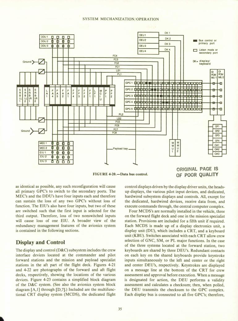
L I FF I F I F I F I F I F I FL I MP I P A AA AA F F F F CF F 1 432143211 I 1 2
U
S SS S R RA R B BB B LL LL LB LA 1212
SYSTEM MECHANIZATION/ OPERATION
00U1
DOU 2
DOU 3
Ground
DK 1 ceutOK 2 DELI Bus control or DK 3 primary port
[EU 3Listen mode or secondary port
FC4 FC3 [3<. display/ FC2 keyboard
Ground
MEC2
EIU 1Payload ba.........J
FIGURE 4-20.—Data bus control.
MM MM UU 12
ORIGINAL PAGE Is OF POOR QUALITY
as identical as possible, any such reconfiguration will cause all primary GPC's to switch to the secondary ports. The MEC's and the DDU's have four inputs each and therefore can sustain the loss of any two GPC's without loss of function. The ELU's also have four inputs, but two of these are switched such that the first input is selected for the third output. Therefore, loss of two nonswitched inputs will cause loss of one EIU. A broader view of the redundancy management features of the avionics system is contained in the following sections.
Display and Control The display and control (D&C) subsystem includes the crew interface devices located at the commander and pilot forward stations and the mission and payload specialist stations in the aft part of the flight deck. Figures 4-21 and 4-22 are photographs of the forward and aft flight decks, respectively, showing the locations of the various devices. Figure 4-23 contains a simplified block diagram of the D&C system. (See also the avionics system block diagram [A,l] through [D,7].) Included are the multifunc-tional CRT display system (MCDS), the dedicated flight
control displays driven by the display driver units, the heads-up displays, the various pilot input devices, and dedicated, hardwired subsystem displays and controls. All, except for the dedicated, hardwired devices, receive data from, and execute commands through, the central computer complex.
Four MCDS's are normally installed in the vehicle, three on the forward flight deck and one in the mission specialist station. Provisions are included for a fifth unit if required. Each MCDS is made up of a display electronics unit, a display unit (DU), which includes a CRT, and a keyboard unit (KBU). Switches associated with each CRT allow crew selection of GNC, SM, or PL major functions. In the case of the three systems located at the forward station, two keyboards are shared by three DEU's. Redundant contacts on each key on the shared keyboards provide keystroke inputs simultaneously to the left and center or the right and center DEU's, respectively. Keystrokes are displayed on a message line at the bottom of the CRT for crew assessment and approval before execution. When a message is designated for action, the DEU performs a validity assessment and calculates a checksum; then, when polled, the DEU transmits the checksum to the GPC complex. Each display bus is connected to all five GPC's; therefore,
35
IL

MAN
U U;[H
SPACE SHUTTLE AVIONICS SYSTEM
-- UN '-'-' _I 2, -- - j—'
g --
4,--
iiwri LILL Lii :
IlL T> I is (.1)11
i1
f -111
FIGURE 4-21.—Forward flight deck.
all DEU messages can be received by all computers if appropriate. All computers listening to the bus will act on the message and, depending on the major function selected, the message content, and the operation in progress, will send appropriate format information and dynamic data to the DEU for display.
Three display driver units service dedicated flight control displays for the commander, pilot, and aft stations, respectively. The data which drive these displays originate in the computer complex, are transmitted over four flight-critical data buses, and are converted and conditioned as required in the DDU. Each DDU has four data bus inputs,
36 ORIGINAL PAGE BLACK AND WHITE PHOTOGRAPI
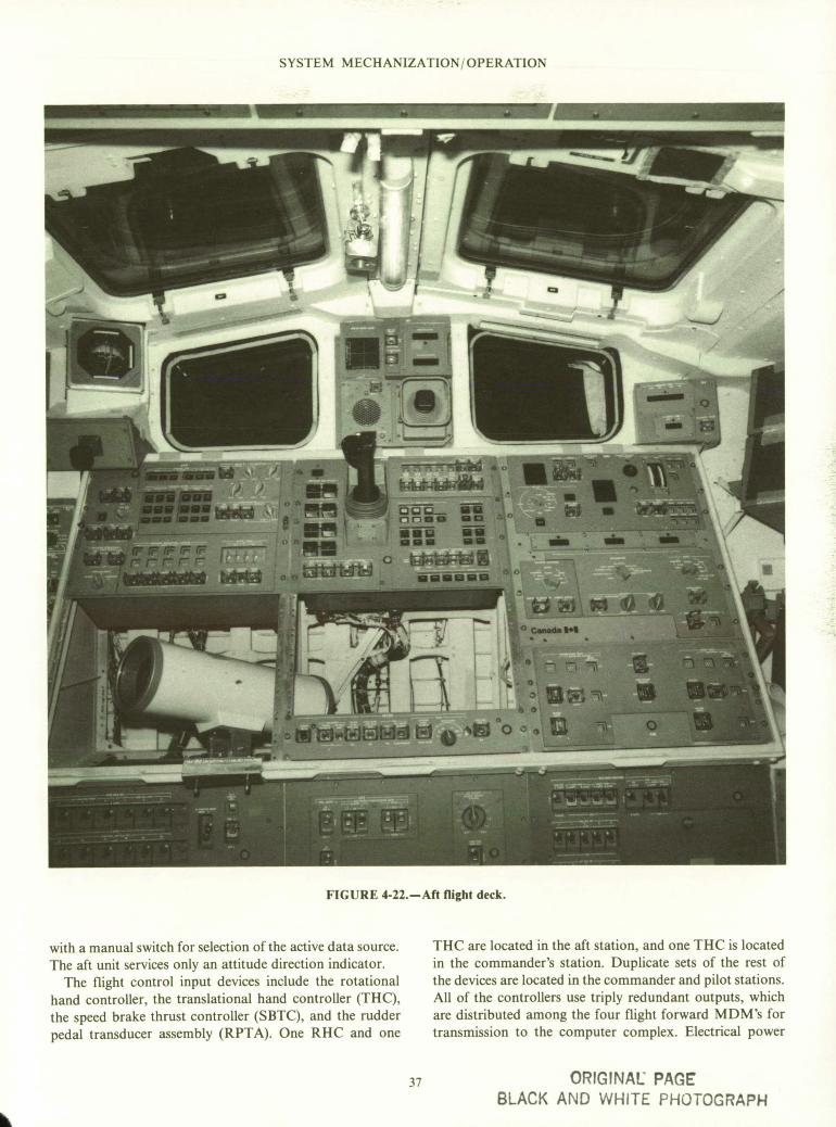
SYSTEM MECHANIZATION/ OPERATION
-= o'*
OWN ' rniSD SD
ass -
iF iF iF IF iF 55 aim
,- r r r r 0
r4#i ti1-tfl S
- . jj j 1 4/ •Q
o iI1t I I o
FIGURE 4-22.—Aft flight deck.
with a manual switch for selection of the active data source. The aft unit services only an attitude direction indicator.
The flight control input devices include the rotational hand controller, the translational hand controller (THC), the speed brake thrust controller (SBTC), and the rudder pedal transducer assembly (RPTA). One RHC and one
THC are located in the aft station, and one THC is located in the commander's station. Duplicate sets of the rest of the devices are located in the commander and pilot stations. All of the controllers use triply redundant outputs, which are distributed among the four flight forward MDM's for transmission to the computer complex. Electrical power
37 ORIGINAL PAGE
BLACK AND WHITE FHOICGRAPH
kk
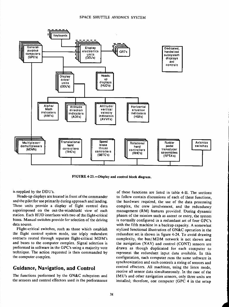
SPACE SHUTTLE AVIONICS SYSTEM
Iffi Keyboards
General- play I I Dedicated,1 purpose i I ronics I I hardwired I computers
u[JJi its
f(DEtYs) I subsystem I (GPC5) t I displays
____ I and I controls
-- Display
-
driver i U units units i displays
(ODU's) I I (HUD's)
direction situation
vertical II Alpha/ Attitude
p Altitude! II Horizontal
Mach Indicators indicators velocity indicators
(AM1's) (ADI's) indicators (HSIs) (AV V l's)
Multiplexer! I pTranslational I II Speed Rotational II Rudder - demuitiplexers I hand brake hand II pedal
(MDM's) controllers thrust controllers II transducer CrHcs) controllers (RHCs) II assemblies
(SBTCs) (RPTA's)
Avionics switches
FIGURE 4-23.—Display and control block diagram.
is supplied by the DDU's. Heads-up displays are located in front of the commander
and the pilot for use primarily during approach and landing. These units provide a display of flight control data superimposed on the out-the-windshield view of each station. Each HUD interfaces with two of the flight-critical buses. Manual switches provide for selection of the driving data source.
Flight-critical switches, such as those which establish the flight control system mode, use triply redundant contacts routed through separate flight-critical MDM's and buses to the computer complex. Signal selection is performed in software in the GPC's using a majority vote technique. The action requested is then commanded by the computer complex.
Guidance, Navigation, and Control The functions performed by the GN&C subsystem and the sensors and control effectors used in the performance
of these functions are listed in table 4-I1. The sections to follow contain discussions of each of these functions, the hardware required, the use of the data processing complex, the crew involvement, and the redundancy management (RM) features provided. During dynamic phases of the mission such as ascent or entry, the system is normally configured in a redundant set of four GPC's with the fifth machine in a backup capacity. A somewhat stylized functional illustration of GN&C operation in the redundant set is shown in figure 4-24. To avoid drawing complexity, the bus/ MDM network is not shown and the navigation (NAV) and control (CONT) sensors are drawn as though duplicated for each computer to represent the redundant input data available. In this configuration, each computer runs the same software in synchronization and each controls a string of sensors and control effectors. All machines, using the listen mode, receive all sensor data simultaneously. In the case of the IMU's and other navigation sensors, only three units are installed; therefore, one computer (GPC 4 in the setup
38

SYSTEM MECHANIZATION/ OPERATION
TABLE 4-11.— Guidance, Navigation, and Control Elements
Mission GN&C function Sensors Control effectors phase
Ascent Thrust vector control (TVC), open- IMU's (3), 2-axis SRB rate gyros Main engine! SRB TVC actuators, loop and powered explicit (2/S RB), 3-axis Orbiter rate reaction control thrusters, OMS guidance; elevon load relief; gyros (4), 2-axis body-mounted actuators, aerosurface actuators RCS/ OMS control; abort accelerometers (4) management
Orbit Attitude/ translation control; IMU IMU's, Orbiter rate gyros, body- OMS actuators, reaction control alignment; rendezvous; remote mounted accelerometers, star thrusters manipulator control; payload trackers (2), rendezvous radar services
Entry Blended RCS/ aerodynamic IMU's, Orbiter rate gyros, body- OMS actuators, reaction control control; angle of attack! bank mounted accelerometers, tacans thrusters, aerosurface actuators angle modulation; g-load, heat (3), air data transducer pulse, footprint management; assemblies (4) tacan-aided navigation; IMU alignment
Terminal area - IMU's, Orbiter rate gyros, body- Aerosurface actuators energy mounted accelerometers, tacans, management air data transducer assemblies
Approach and - IMU's, Orbiter rate gyros, body- Aerosurface actuators, nosewheel landing mounted accelerometers, tacans, steering actuators, wheel brakes
air data transducer assemblies, microwave scanning beam landing systems (3)
shown in fig. 4-24) has no sensor to control and can receive these data only by listening to the other three. Each IMU provides the sensed inertial attitude and acceleration of the vehicle. These data are compared, after individual sensor compensation (COMP) and calibration (CALIB), in fault detection and identification (FDI) algorithms which detect out-of-tolerance conditions. A navigation state vector is calculated (as indicated schematically in the diagram, by the box with the integral (INT) sign) using data from each IMU which pass the FDI test. If data from othef navigation sensors such as tacan or MSBLS are to be used (i.e., during entry), they are periodically incorporated, after passing though an FDI test, into the state vector using a Kalman filter algorithm. This update process removes or reduces any systematic state vector errors caused by IMU drift, etc. The state vector is then passed to the guidance (GUID) algorithm, where a vehicle guidance command is generated and sent to the flight control module. Here, the outer loop guidance command is combined with the inner loop commands generated in the flight control algorithm on the basis of inputs from selected flight control sensors, such as rate gyros and accelerometers. The resultant command from each computer is sent to the control effectors, where the final command selection process is conducted. The reader
should keep in mind that this discussion of GN&C operation is simplified and does not include subtle variations such as those introduced by different sample rates and extraneous uses of data.
GN&C Sensors
The physical locations of the sensors used by the GN&C system are dictated by the structural dynamics of the vehicle, the required relationship to the center of gravity, and, to some extent in the case of the tracking devices, by the associated antenna requirements. The inertial measurement unit, star tracker, rate gyro, accelerometer, and air data sensors are described in the following subsections. The others (tacan, microwave scanning beam landing system, and rendezvous radar) are discussed in the Communications and Tracking section.
Inertial Measurement Units/Star Trackers,
Three IMU's and two associated star trackers are installed on the navigation base just forward of the Orbiter lower equipment bay. The navigation base is a rigid structural beam constructed to maintain a precise angular relationship between the IMU's and the star trackers for
39
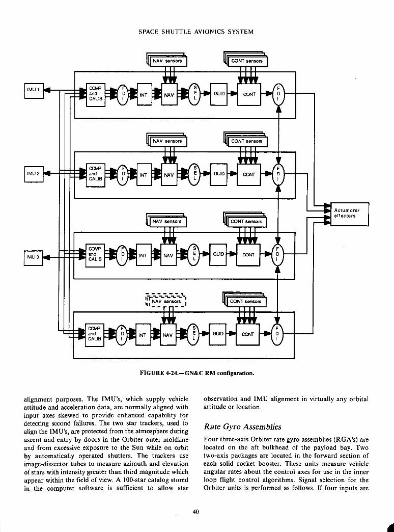
SPACE SHUTTLE AVIONICS SYSTEM
FIGURE 4-24.—GN&C RM configuration.
alignment purposes. The IMU's, which supply vehicle attitude and acceleration data, are normally aligned with input axes skewed to provide enhanced capability for detecting second failures. The two star trackers, used to align the IMU's, are protected from the atmosphere during ascent and entry by doors in the Orbiter outer moldline and from excessive exposure to the Sun while on orbit by automatically operated shutters. The trackers use image-dissector tubes to measure azimuth and elevation of stars with intensity greater than third magnitude which appear within the field of view. A 100-star catalog stored in the computer software is sufficient to allow star
observation and IMU alignment in virtually any orbital attitude or location.
Rate Gyro Assemblies
Four three-axis Orbiter rate gyro assemblies (RGA's) are located on the aft bulkhead of the payload bay. Two two-axis packages are located in the forward section of each solid rocket booster. These units measure vehicle angular rates about the control axes for use in the inner loop flight control algorithms. Signal selection for the Orbiter units is performed as follows. If four inputs are
40

SYSTEM MECHANIZATION/ OPERATION
present, the higher of the two midvalues is selected. If the input from any unit diverges from the other three beyond a preset threshold, the input is rejected, the RGA is declared inoperative, and the midvalue of the remaining three inputs is selected. A form of quadruple middle-value selection is also performed on the SRB gyros by comparing data from all four devices.
Accelerometer Assemblies
Four two-axis body-mounted accelerometer packages are located in the Orbiter forward equipment bays. These instruments measure normal and lateral acceleration and are also used in the inner loop flight control calculations. The quadruple middle-value signal selection process used is identical to that used for the Orbiter rate gyros.
Air Data
Two pitot/static probes are located on revolving doors on either side of the Orbiter forward fuselage. Each probe provides four pneumatic inputs, three ram air and one static air, in parallel to two air data transducer assemblies (ADTA's). The pneumatic pressures are measured and converted to digital signals in the ADTA's and sent by way of flight forward MDM's to the GPC's as shown in figure 4-25. The data are used to calculate altitude, airspeed, Mach number, angle of attack, etc., for display and for use in the entry navigation, guidance, and flight control systems. Redundancy management in this area
is particularly complicated in that the quadruply redundant sensor measurements provided to the GPC's are not really independent because only two probes are installed. Further, sideslip effects can cause differences in measurements from side to side that are difficult to distinguish from failure effects, and significant transients can be expected, especially during Mach I transition. Functionally, the RM logic first determines the deploy-ment status of the probes and their usability based on communication faults and other checks. The selection filter then either averages the usable inputs or selects one if only one is available - first on a side basis, then overall
and sends the output to the user process after passing it through a transient filter. Comparison tests against preset thresholds are made to detect and identify failures, again first on a side basis. If the two inputs from a side miscompare by more than the threshold, the selected value from the other side is used, after a sideslip correction is applied, to isolate the faulty unit. If no input is available from the other side, a dilemma situation is declared and annunciated to the crew.
GN&C Control Functions
Four distinctly different dynamic control functions are performed by the GN&C system during a typical mission. These include
• Hydraulic actuator control of SRB and main engine thrust vectors and Orbiter aerodynamic control surfaces during ascent and entry
FIGURE 4-25.—Air data system.
41
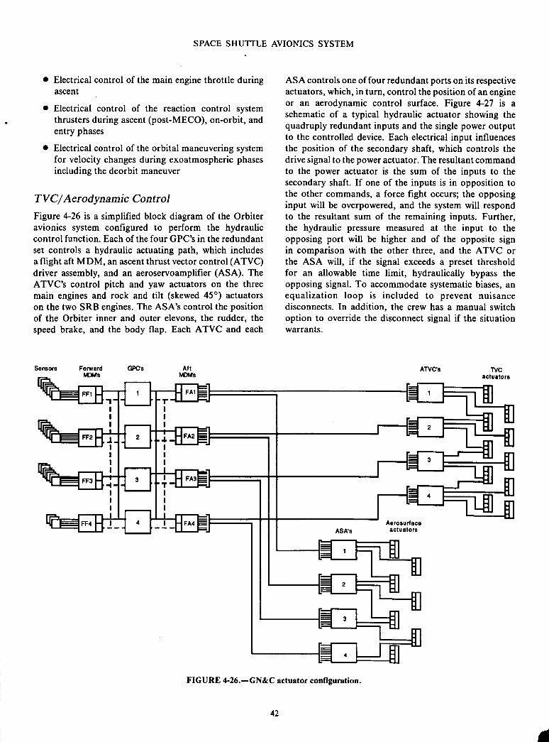
SPACE SHUTTLE AVIONICS SYSTEM
• Electrical control of the main engine throttle during ascent
• Electrical control of the reaction control system thrusters during ascent (post-MECO), on-orbit, and entry phases
• Electrical control of the orbital maneuvering system for velocity changes during exoatmospheric phases including the deorbit maneuver
TVC/Aerodynamic Control Figure 4-26 is a simplified block diagram of the Orbiter avionics system configured to perform the hydraulic control function. Each of the four GPC's in the redundant set controls a hydraulic actuating path, which includes a flight aft MDM, an ascent thrust vector control (ATVC) driver assembly, and an aeroservoamplifier (ASA). The ATVC's control pitch and yaw actuators on the three main engines and rock and tilt (skewed 45°) actuators on the two SRB engines. The ASA's control the position of the Orbiter inner and outer elevons, the rudder, the speed brake, and the body flap. Each ATVC and each
ASA controls one of four redundant ports on its respective actuators, which, in turn, control the position of an engine or an aerodynamic control surface. Figure 4-27 is a schematic of a typical hydraulic actuator showing the quadruply redundant inputs and the single power output to the controlled device. Each electrical input influences the position of the secondary shaft, which controls the drive signal to the power actuator. The resultant command to the power actuator is the sum of the inputs to the secondary shaft. If one of the inputs is in opposition to the other commands, a force fight occurs; the opposing input will be overpowered, and the system will respond to the resultant sum of the remaining inputs. Further, the hydraulic pressure measured at the input to the opposing port will be higher and of the opposite sign in comparison with the other three, and the ATVC or the ASA will, if the signal exceeds a preset threshold for an allowable time limit, hydraulically bypass the opposing signal. To accommodate systematic biases, an equalization loop is included to prevent nuisance disconnects. In addition, the crew has a manual switch option to override the disconnect signal if the situation warrants.
Sensors Forward GPCs Aft ATVCs TVC MWS Mfltts
FIGURE 4-26.—GN&C actuator configuration.
42
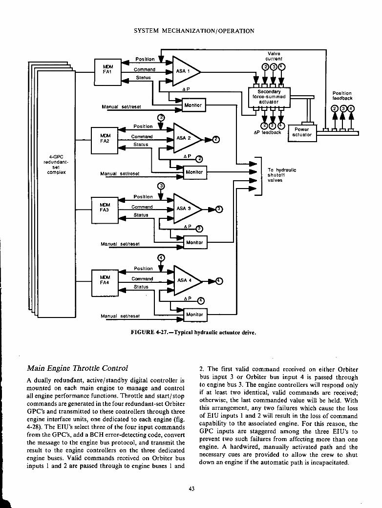
SYSTEM MECHANIZATION/ OPERATION
FIGURE 4-27.—Typical hydraulic actuator drive.
Main Engine Throttle Control
A dually redundant, active/standby digital controller is mounted on each main engine to manage and control all engine performance functions. Throttle and start/ stop commands are generated in the four redundant-set Orbiter GPC's and transmitted to these controllers through three engine interface units, one dedicated to each engine (fig. 4-28). The EIU's select three of the four input commands from the GPC's, add a BCH error-detecting code, convert the message to the engine bus protocol, and transmit the result to the engine controllers on the three dedicated engine buses. Valid commands received on Orbiter bus inputs 1 and 2 are passed through to engine buses 1 and
2. The first valid command received on either Orbiter bus input 3 or Orbiter bus input 4 is passed through to engine bus 3. The engine controllers will respond only if at least two identical, valid commands are received; otherwise, the last commanded value will be held. With this arrangement, any two failures which cause the loss of EIU inputs 1 and 2 will result in the loss of command capability to the associated engine. For this reason, the GPC inputs are staggered among the three EIU's to prevent two such failures from affecting more than one engine. A hardwired, manually activated path and the necessary cues are provided to allow the crew to shut down an engine if the automatic path is incapacitated.
43
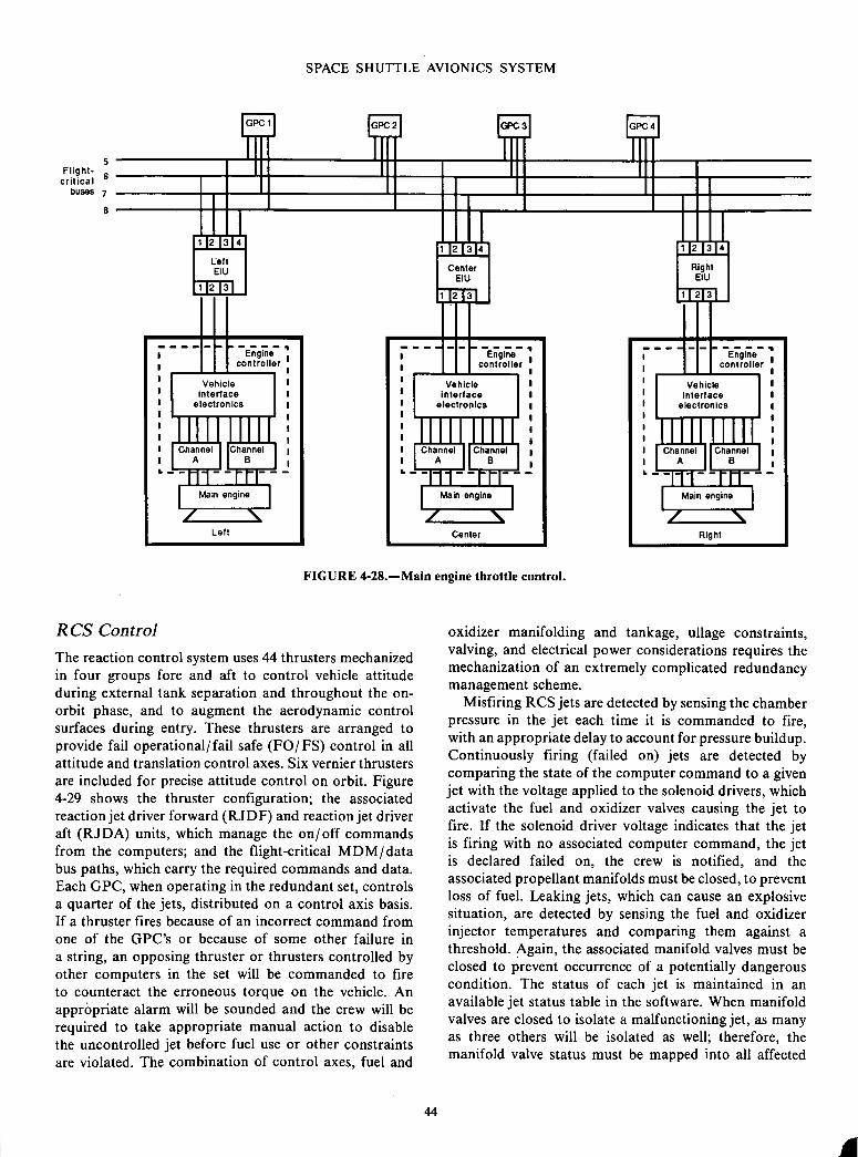
SPACE SHUTTLE AVIONICS SYSTEM
GPC1I IGPC2
Left I'Center I
EI I Right E1 U
- I ElU I I U
I rrEnge Engine -controller I I Controller controller
Vehicle 1 Vehicle I I lntertace I interlace I e I
I electronics I electronics I I cs
1J__ Eng e
iiiChannel Channel Channel Channel p I hannel
A B I A B B
--- " ''Main engine Main engine
___ine
Left Center Right
FIGURE 4-28.—Main engine throttle control.
Flight. critical
buses
RCS Control
The reaction control system uses 44 thrusters mechanized in four groups fore and aft to control vehicle attitude during external tank separation and throughout the on-orbit phase, and to augment the aerodynamic control surfaces during entry. These thrusters are arranged to provide fail operational/ fail safe (FO/FS) control in all attitude and translation control axes. Six vernier thrusters are included for precise attitude control on orbit. Figure 4-29 shows the thruster configuration; the associated reaction jet driver forward (RJDF) and reaction jet driver aft (RJDA) units, which manage the on/off commands from the computers; and the flight-critical MDM/data bus paths, which carry the required commands and data. Each GPC, when operating in the redundant set, controls a quarter of the jets, distributed on a control axis basis. If a thruster fires because of an incorrect command from one of the GPC's or because of some other failure in a string, an opposing thruster or thrusters controlled by other computers in the set will be commanded to fire to counteract the erroneous torque on the vehicle. An appropriate alarm will be sounded and the crew will be required to take appropriate manual action to disable the uncontrolled jet before fuel use or other constraints are violated. The combination of control axes, fuel and
oxidizer manifolding and tankage, ullage constraints, valving, and electrical power considerations requires the mechanization of an extremely complicated redundancy management scheme.
Misfiring RCS jets are detected by sensing the chamber pressure in the jet each time it is commanded to fire, with an appropriate delay to account for pressure buildup. Continuously firing (failed on) jets are detected by comparing the state of the computer command to a given jet with the voltage applied to the solenoid drivers, which activate the fuel and oxidizer valves causing the jet to fire. If the solenoid driver voltage indicates that the jet is firing with no associated computer command, the jet is declared failed on, the crew is notified, and the associated propellant manifolds must be closed, to prevent loss of fuel. Leaking jets, which can cause an explosive situation, are detected by sensing the fuel and oxidizer injector temperatures and comparing them against a threshold. Again, the associated manifold valves must be closed to prevent occurrence of a potentially dangerous condition. The status of each jet is maintained in an available jet status table in the software. When manifold valves are closed to isolate a malfunctioning jet, as many as three others will be isolated as well; therefore, the manifold valve status must be mapped into all affected
44
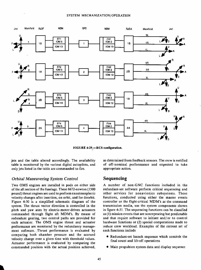
Fjf! -
U rR F
E
FF I II I ___
I ____________ I
IiIOM
FA I
2
lB
I I
IOMIO 1L
I
______ ______
LR
1A
I FF2 I10M5II II
I I ___
' '
I I FA2 I2B[ 3R
10M 132 I 112I 10M 10
3L _______ 4D?^R A
do R
.4" 5
2B
I FF3II
I _______ I I I 2R
A 4 I 2L 1CM 13 I I _______ M
L
4A
SYSTEM MECHANIZATION/ OPERATION
Jet Manifold RiDE Pvtivi GPC MM RJDA Manifold Jet
L+D
DV
L
FIGURE 4-29.—RCS configuration.
jets and the table altered accordingly. The availability table is monitored by the various digital autopilots, and only jets listed in the table are commanded to fire.
Orbital Maneuvering System Control
Two OMS engines are installed in pods on either side of the aft section of the fuselage. These 6672-newton (1500 pound) thrust engines are used to perform exoatmospheric velocity changes after insertion, on orbit, and for deorbit. Figure 4-30 is a simplified schematic diagram of the system. The thrust vector direction is controlled in the pitch and yaw axes by electric-motor-driven actuators commanded through flight aft MDM's. By means of redundant gearing, two control paths are provided for each actuator. The OMS engine thrust and actuator performance are monitored by the redundancy manage-ment software. Thrust performance is evaluated by comparing both chamber pressure and the accrued velocity change over a given time with threshold values. Actuator performance is evaluated by comparing the commanded position with the actual position achieved,
as determined from feedback sensors. The crew is notified of off-nominal performance and expected to take appropriate action.
Sequencing A number of non-GNC functions included in the redundant-set software perform critical sequencing and other services for nonavionics subsystems. These functions, conducted using either the master events controller or the flight-critical MDM's as the command transmission media, use the system components shown in figure 4-31. The sequencing functions can be classified as (1) mission events that are nonrepeating but predictable and that require software to initiate and/or to control hardware functions or (2) special computations made to reduce crew workload. Examples of the current set of such functions include
• Redundant-set launch sequence which controls the final count and lift-off operations
• Main propulsion system data and display sequence
45

SPACE SHUTTLE AVIONICS SYSTEM
MDMI ' ktMI
FA1 1FA21
d- Fuel Oxidizer
^ —i —i _g
Primary rimary yaw pitch
actuator actuator
econdary Secondary yaw pitch
actuator actuator
Left OMS engine
FA3 FA4
dFuel Oxidizer
^ — ^ — 9 gg Primary
yaw actuator
Secondary yaw
actuator
Right OMS engine
Primary pitch
actuator
Secondary pitch
actuator
FIGURE 4-30.—OMS configuration.
• SRB MDM data acquisition
• Main engine operations sequence
• SRB separation sequence
• Main propulsion system propellant-dump sequence
• Abort control sequence
• Abort OMS/ RCS interconnect
• Orbiter vent door control
• Landing gear isolation valve control
• RCS/ RCS crossfeed and reconfiguration
• RCS quantity monitor
• Orbit OMS/RCS interconnect
• OMS firing sequence
• OMS to RCS propellant gauging
• Master events controller subsystem operating program
• Main engine subsystem operating program
1t111 Master L] Critical I 144—I events I 1 pyrotechnic
controller events
GPC1
Master Noncritical events IEC
controller events GPC2 2
MDM A E31— (typ)
Dual command
events E4
MDM B (typ)
Flight-critical
buses
FIGURE 4-31.—Sequencing configuration.
46
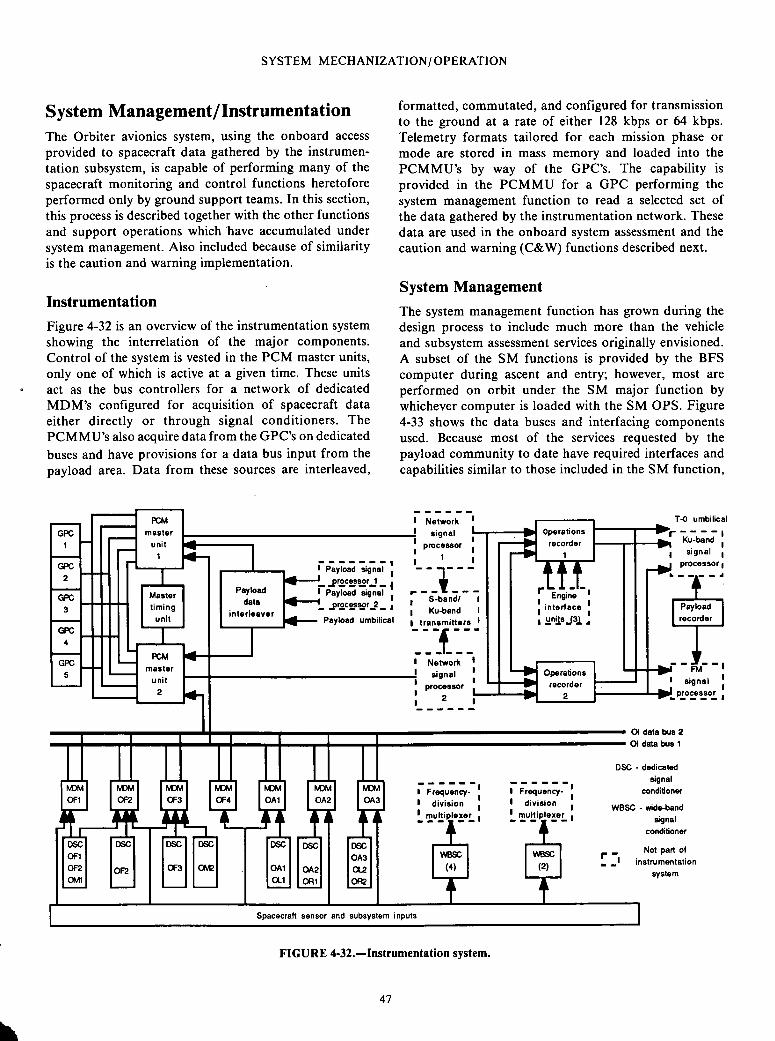
SYSTEM MECHANIZATION! OPERATION
System Management/ Instrumentation The Orbiter avionics system, using the onboard access provided to spacecraft data gathered by the instrumen-tation subsystem, is capable of performing many of the spacecraft monitoring and control functions heretofore performed only by ground support teams. In this section, this process is described together with the other functions and support operations which have accumulated under system management. Also included because of similarity is the caution and warning implementation.
Instrumentation
Figure 4-32 is an overview of the instrumentation system showing the interrelation of the major components. Control of the system is vested in the PCM master units, only one of which is active at a given time. These units act as the bus controllers for a network of dedicated MDM's configured for acquisition of spacecraft data either directly or through signal conditioners. The PCMMU's also acquire data from the GPC's on dedicated buses and have provisions for a data bus input from the payload area. Data from these sources are interleaved,
formatted, commutated, and configured for transmission to the ground at a rate of either 128 kbps or 64 kbps. Telemetry formats tailored for each mission phase or mode are stored in mass memory and loaded into the PCMMU's by way of the GPC's. The capability is provided in the PCMMU for a GPC performing the system management function to read a selected set of the data gathered by the instrumentation network. These data are used in the onboard system assessment and the caution and warning (C&W) functions described next.
System Management
The system management function has grown during the design process to include much more than the vehicle and subsystem assessment services originally envisioned. A subset of the SM functions is provided by the BFS computer during ascent and entry; however, most are performed on orbit under the SM major function by whichever computer is loaded with the SM OPS. Figure 4-33 shows the data buses and interfacing components used. Because most of the services requested by the payload community to date have required interfaces and capabilities similar to those included in the SM function,
PcM I Network 1 T-O umbilical
1 unit I •
VEngiZ
Ku-band
processor • ___ I ___ GPC Payload ;
I signal
2
__ Master Payload signal - - - - 3
processor
- processor 1 fd
___Payload
GPC master I proc
L Ipi __ ----
timing - 3 Ku-band I in
S-bandl I dat. intert.aver
cy r terface I Payload I I unit Payload umbilical transmitters I I nj8J3 recorder
GC
5 I signal Operations GPC I Network PcM master FM
unit - recorder I signal 2 processor L...... 2
or
:--------
01 data bus 2 01 data bus 1 DSC - dedicated
signal KM NUM kum WIVI I- I Frequency- conditioner
I • I division u WBSC - wide-band OF1 0F2
If
division '
instrumentation (2) 4
multip lexer DSC DSC OSC DSC I DSC er mu lt ip le xer signal conditioner
oft0F2 0F3 Cfv OAI 0A2
JDSC
I WB I I W9 I r 0F2
- Not part of
ORII I system
()I
-
I Spacecraft sensor and subsystem inputs I
FIGURE 4-32.—Instrumentation system.
47
hk
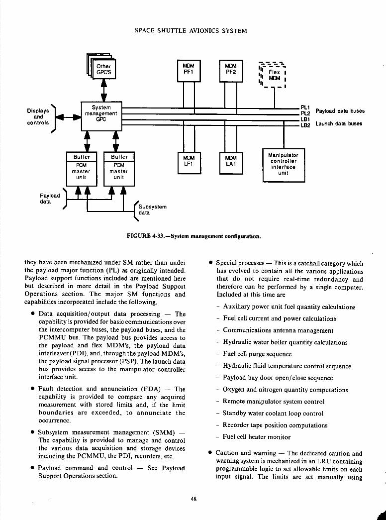
Displays and
controls
System management
GPC
PL1 PL2 Payload data buses
LB1 LB2 Launch data buses
SPACE SHUTTLE AVIONICS SYSTEM
Other
MOM MOM •:.
GPCS
PF1 PF2
Flex I MDA
______
I_________ MOM
ii Manipulator Buffer Buffer I I
FM FM LF1 LA1controller
master masterinterface
unit unitunit
Payload data
Subsystem data
FIGURE 4-33.—System management configuration.
they have been mechanized under SM rather than under the payload major function (PL) as originally intended. Payload support functions included are mentioned here but described in more detail in the Payload Support Operations section. The major SM functions and capabilities incorporated include the following.
• Data acquisition/ output data processing - The capability is provided for basic communications over the intercomputer buses, the payload buses, and the PCMMU bus. The payload bus provides access to the payload and flex MDM's, the payload data interleaver (PDI), and, through the payload MDM's, the payload signal processor (PSP). The launch data bus provides access to the manipulator controller interface unit.
• Fault detection and annunciation (FDA) - The capability is provided to compare any acquired measurement with stored limits and, if the limit boundaries are exceeded, to annunciate the occurrence.
• Subsystem measurement management (SMM) - The capability is provided to manage and control the various data acquisition and storage devices including the PCMMU, the PDI, recorders, etc.
• Payload command and control - See Payload Support Operations section.
• Special processes - This is a catchall category which has evolved to contain all the various applications that do not require real-time redundancy and therefore can be performed by a single computer. Included at this time are
- Auxiliary power unit fuel quantity calculations
- Fuel cell current and power calculations
- Communications antenna management
- Hydraulic water boiler quantity calculations
- Fuel cell purge sequence
- Hydraulic fluid temperature control sequence
- Payload bay door open/close sequence
- Oxygen and nitrogen quantity computations
- Remote manipulator system control
- Standby water coolant loop control
- Recorder tape position computations
- Fuel cell heater monitor
• Caution and warning - The dedicated caution and warning system is mechanized in an LRU containing programmable logic to set allowable limits on each input signal. The limits are set manually using
48
4
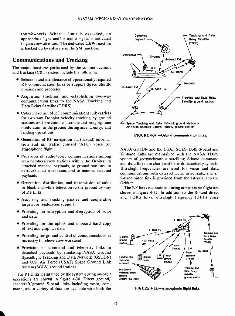
SYSTEM MECHANIZATION! OPERATION
thumbwheels. When a limit is exceeded, an appropriate light and/or audio signal is activated to gain crew attention. The dedicated C&W function is backed up by software in the SM function.
Communications and Tracking The major functions performed by the communications and tracking (C&T) system include the following.
• Selection and maintenance of operationally required RF communication links to support Space Shuttle missions and processes
• Acquiring, tracking, and establishing two-way communication links to the NASA Tracking and Data Relay Satellite (TDRS)
• Coherent return of RF communications link carriers for two-way Doppler velocity tracking by ground stations and provision of turnaround ranging tone modulation to the ground during ascent, entry, and landing operations
• Generation of RF navigation aid (navaid) informa-tion and air traffic control (ATC) voice for atmospheric flight
• Provision of audio/voice communications among crewmembers/crew stations within the Orbiter, to attached manned payloads, to ground stations, to extravehicular astronauts, and to manned released payloads
• Generation, distribution, and transmission of color or black and white television to the ground by way of RF links
• Acquiring and tracking passive and cooperative targets for rendezvous support
• Providing for encryption and decryption of voice and data
• Providing for the uplink and onboard hard copy of text and graphics data
• Providing for ground control of communications as necessary to relieve crew workload
• Provision of command and telemetry links to detached payloads by emulating NASA Ground Spaceflight Tracking and Data Network (GSTDN) and U.S. Air Force (USAF) Space Ground Link System (SGLS) ground stations
The RF links maintained by the system during on-orbit operations are shown in figure 4-34. Direct ground/ spacecraft/ ground S-band links including voice, com-mand, and a variety of data are available with both the
Detached Tracking and Data payload Relay Satellite
AstronautS—band S band PM
S)
UHF
S—band FMnd
g and Data Relay ground station
Space Tracking and Data Network ground station or Air Force Satellite Control Facility ground station
FIGURE 4-34.—Orbital communication links.
NASA GSTDN and the USAF SGLS. Both S-band and Ku-band links are maintained with the NASA TDRS system of geosynchronous satellites; S-band command and data links are also possible with detached payloads. Ultrahigh frequencies are used for voice and data communications with extravehicular astronauts, and an S-band video link is provided from the astronaut to the Orbiter.
The RF links maintained during atmospheric flight are shown in figure 4-35. In addition to the S-band direct and TDRS links, ultrahigh frequency (UHF) voice
S—baM >
8—band PM
S—bandTracking and Data Relay
c(%d ATC voice Satellite station________ UHF
-
(TDRS) an
LbandKu—band Radar
Lanng site Control Taoan altimeter / two—way
c-v approach station
Micr owave Tracking and
ecarming beam Data Relay -I- landing Satellite
system—Ku--band or,rd station
FIGURE 4-35.—Atmospheric flight links.
49
kk

Ku–wide–band system S–band (payload)
S–band hemi 3 L–band taoan - \
SPACE SHUTTLE AVIONICS SYSTEM
FIGURE 4-36.—Hardware groupings.
communications coverage is provided for ATC purposes. Three navaid systems are included for use after blackout: the tacan system at L-band, the MSBLS at Ku-band, and the radar altimeters at C-band.
The hardware associated with the various communi-cations links and the other functions of the system can be grouped as shown in figure 4-36. Each of these groupings is discussed in the paragraphs to follow. The multiple antennas used in the system are shown in figure 4-37. All are flush-mounted and overlaid with thermal protective material except for the UHF airlock and the Ku-band deployable antennas. The antenna locations were chosen to optimize coverage to the extent possible within the constraints of available mounting space.
S-Band Network System
Figure 4-38 contains a block diagram of the S-band network system, which provides tracking and two-way communications by way of phase modulated (PM) links directly to the ground or through the TDRS, and transmission of wide-band data directly to the ground
3 L–band tacan
FIGURE 4-37.—Antenna locations.
50
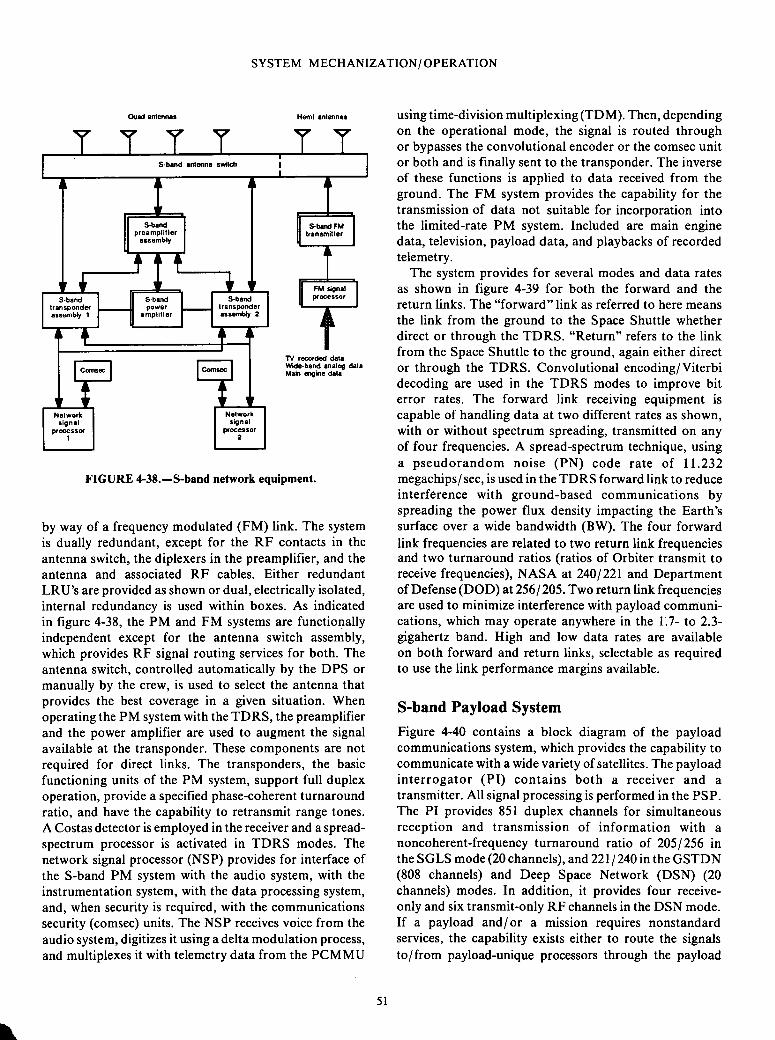
SYSTEM MECHANIZATION! OPERATION
Quad antennas Hemi antennae
S-band antenna switch
S-band II S-band FM preamplifier II transmitter
assembly U
V V _____ V V II FM signal
S-band S-band S-band U processor
transponder power transponder
assembly I amplifier assembly 2 4
_________ TV recorded data
Cemsec ComsecMainmigme data Wide-band analog data
Network Network signal signal
processor processor
FIGURE 4-38.—S-band network equipment.
by way of a frequency modulated (FM) link. The system is dually redundant, except for the RF contacts in the antenna switch, the diplexers in the preamplifier, and the antenna and associated RF cables. Either redundant LRU's are provided as shown or dual, electrically isolated, internal redundancy is used within boxes. As indicated in figure 4-38, the PM and FM systems are functionally independent except for the antenna switch assembly, which provides RF signal routing services for both. The antenna switch, controlled automatically by the DPS or manually by the crew, is used to select the antenna that provides the best coverage in a given situation. When operating the PM system with the TDRS, the preamplifier and the power amplifier are used to augment the signal available at the transponder. These components are not required for direct links. The transponders, the basic functioning units of the PM system, support full duplex operation, provide a specified phase-coherent turnaround ratio, and have the capability to retransmit range tones. A Costas detector is employed in the receiver and a spread-spectrum processor is activated in TDRS modes. The network signal processor (NSP) provides for interface of the S-band PM system with the audio system, with the instrumentation system, with the data processing system, and, when security is required, with the communications security (comsec) units. The NSP receives voice from the audio system, digitizes it using a delta modulation process, and multiplexes it with telemetry data from the PCMMU
using time-division multiplexing (TDM). Then, depending on the operational mode, the signal is routed through or bypasses the convolutional encoder or the comsec unit or both and is finally sent to the transponder. The inverse of these functions is applied to data received from the ground. The FM system provides the capability for the transmission of data not suitable for incorporation into the limited-rate PM system. Included are main engine data, television, payload data, and playbacks of recorded telemetry.
The system provides for several modes and data rates as shown in figure 4-39 for both the forward and the return links. The "forward" link as referred to here means the link from the ground to the Space Shuttle whether direct or through the TDRS. "Return" refers to the link from the Space Shuttle to the ground, again either direct or through the TDRS. Convolutional encoding! Viterbi decoding are used in the TDRS modes to improve bit error rates. The forward link receiving equipment is capable of handling data at two different rates as shown, with or without spectrum spreading, transmitted on any of four frequencies. A spread-spectrum technique, using a pseudorandom noise (PN) code rate of 11.232 megachips/ sec, is used in the TDRS forward link to reduce interference with ground-based communications by spreading the power flux density impacting the Earth's surface over a wide bandwidth (BW). The four forward link frequencies are related to two return link frequencies and two turnaround ratios (ratios of Orbiter transmit to receive frequencies), NASA at 240/221 and Department of Defense (DOD) at 256/205. Two return link frequencies are used to minimize interference with payload communi-cations, which may operate anywhere in the 1.7- to 2.3-gigahertz band. High and low data rates are available on both forward and return links, selectable as required to use the link performance margins available.
S-band Payload System
Figure 4-40 contains a block diagram of the payload communications system, which provides the capability to communicate with a wide variety of satellites. The payload interrogator (P1) contains both a receiver and a transmitter. All signal processing is performed in the PSP. The P1 provides 851 duplex channels for simultaneous reception and transmission of information with a noncoherent-frequency turnaround ratio of 205/256 in the SGLS mode (20 channels), and 221/ 240 in the GSTDN (808 channels) and Deep Space Network (DSN) (20 channels) modes. In addition, it provides four receive-only and six transmit-only RF channels in the DSN mode. If a payload and/or a mission requires nonstandard services, the capability exists either to route the signals to/from payload-unique processors through the payload
51
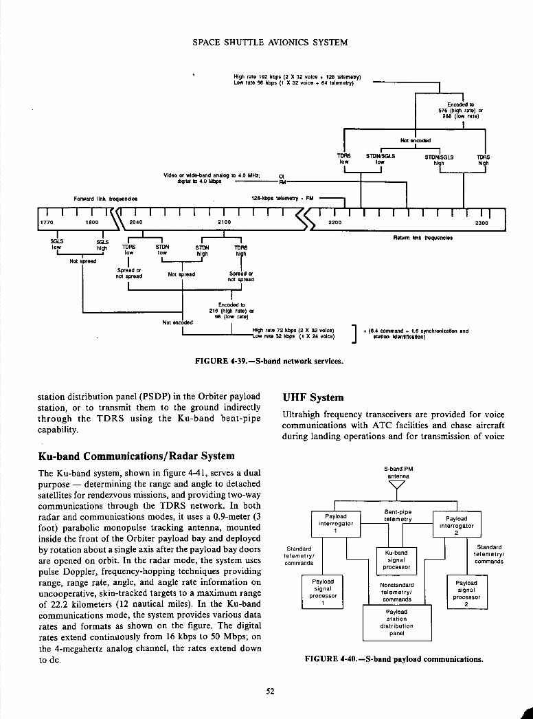
SPACE SHUTTLE AVIONICS SYSTEM
High rate 192 kbps (2 X 32 voice + 128 telemetry) Low rate 96 kbps (1 X 32 voice + 64 telemetry)
Encoded to 576 (high rate) or
288 (low rate)
II
Not encoded I
TORS STDP4'SGLS STDN/ISGLS tow low hint.
Video or wide-band analog to 4.0 MHz; a digital to 4.0 Mbpa
Forward link frequencies
128-kbps telemetry . FM
I 1770 1800 2040 2100
I I I I SGS SGlJs I I I I low high WAS STDN STON WAS
I • low low hih hi h
Not spread I I Spread or
g
not spread Not spread Spread or I not spread
JdedE
ncoded
to 216 (high rate) or
96 (low rate)
I I High rate 72 kbps (2 X 32 voice) ...ow rate 32 kbps (I X 24 voIce)
Return link frequencies
1 + (6.4 command + 1.6 synchronization and
JStation Identification)
FIGURE 4-39.—S-band network services.
station distribution panel (PSDP) in the Orbiter payload UHF System station, or to transmit them to the ground indirectly through the TDRS using the Ku-band bent-pipe Ultrahigh frequency transceivers are provided for voice
capability, communications with ATC facilities and chase aircraft during landing operations and for transmission of voice
Ku-band Communications/ Radar System
The Ku-band system, shown in figure 441, serves a dual purpose - determining the range and angle to detached satellites for rendezvous missions, and providing two-way communications through the TDRS network. In both radar and communications modes, it uses a 0.9-meter (3 foot) parabolic monopulse tracking antenna, mounted inside the front of the Orbiter payload bay and deployed by rotation about a single axis after the payload bay doors are opened on orbit. In the radar mode, the system uses pulse Doppler, frequency-hopping techniques providing range, range rate, angle, and angle rate information on uncooperative, skin-tracked targets to a maximum range of 22.2 kilometers (12 nautical miles). In the Ku-band communications mode, the system provides various data rates and formats as shown on the figure. The digital rates extend continuously from 16 kbps to 50 Mbps; on the 4-megahertz analog channel, the rates extend down to dc.
S-band PM antenna
Bent-pipe Payload telemetry Payload
interrogator interrogator 2
Standard Standard
telemetry/ Ku-band telemetry/
commands I signalco corn ends
processor
PayloadNonstandard Payload d
signaltelemetry/ signal
processorcommands processor
1 2
FIGURE 4-40.—S-band payload communications.
52

SYSTEM MECHANIZATION! OPERATION
Radar rendezvous range • 22 km (12 n. ml.) maximum, passive payload > • 550 km (300 n. ml.) maximum, active payload
Payload
Ku–band deployed assembly
Ku–band radar/corn eIeotroflIc assemblies
Avionic bay 3/
Tracking and Data Mode 1 Relay Satellite • 50 Mbps - wide–band payload (TDRS) • 2 Mbps - stored or payload • 192 kbps - telemetry and voice
IJMode 2
'
• 4.5 MHz analog - TV or payload or 4 Mbps - digital payload
• 2 Mbps - stored or payload • 192 kbps - telemetry and voice
0 216 kbps • 72–kbps commands • 128–kbps text
and graphics • 16–kbps synchronization
Tracking and Data Relay Satellite ground station
FIGURE 4-41.—Ku-band radar/communication subsystem.
to and reception of voice and telemetry data from extravehicular astronauts while on orbit. Two antennas are provided, one in the airlock and one on the bottom of the Orbiter. A two-way voice interface with the Orbiter audio system is included, giving astronauts performing extravehicular activity (EVA) access to Orbiter voice communications on as many as three voice channels. Availability of three channels allows direct voice contact with the ground or the Orbiter crew, and provides for recording of the astronauts' conversations.
Extravehicular Maneuvering Unit Television System A wide-band S-band FM receiver is provided for reception of video transmitted from the EVA helmet camera. The S-band hemispheric antennas and a spare port of the switch assembly of the S-band network communications equipment (fig. 4-38) are used to route the video signal to a 40-megahertz wide-band FM receiver. This receiver demodulates the video signal and routes it to the television (TV) system.
Audio Distribution System
The audio distribution system (ADS), shown in figure 4-42, provides intercom and radio access functions for the various crew stations and hardline "subscribers" involved in a mission. It includes facilities for audio processing, mixing, amplification, volume control, isolation, switching, and distribution. It provides paging capability, communication over various alternative bus circuits, distribution of caution and warning signals, and communication with the ground crews during preflight checkout. The ADS includes six audio terminal units (ATU's) distributed as indicated in the figure, two speaker microphone units, and an audio central control unit (ACCU).
Television System
The TV system includes as many as nine onboard cameras, two large-screen monitors, two portable viewfinder monitors, and the associated switching and control logic. Three inputs are provided for TV signals from payloads and one output for viewing in an attached manned
53
I.

SPACE SHUTTLE AVIONICS SYSTEM
Commander - - Not part of audio system ATU1
Network Experiments I signal
Pilot Ii processors
recorder
ATU 2 i—_i I - -----Tacans
Mission I specialist I__i I I GSE umbilical
ATU 3 L__jAudio central Payload bay station control unit Docking ring
Attached payloads Airlock
P ATU 4 _________________ Television system
ATU 5 mike unit
_9^^
Caution and Mid- warning
r ^mike unjj ATU 6
,
FIGURE 4-42.—Audio distribution system.
payload. The cameras, either color or black and white depending on the lens assembly installed, may be located in the cabin, at various locations in the payload bay, and on the RMS arm. All externally mounted cameras may be controlled remotely from the cabin. The capability is included to record TV data onboard and/or to transmit it to the ground as indicated previously.
Navaids
Three navaid systems are installed on the Orbiter for use during postblackout through landing phases (fig. 4-43). The tacan units, used from an altitude of approximately 21.3 kilometers (70 000 feet) to final approach, are versions of units widely used in military aircraft, modified slightly to interface with Orbiter systems. They provide slant range and bearing to a selected ground station. The MSBLS, used from an altitude of approximately 3 kilometers (10 000 feet) to touchdown, also a modified version of a military system, provides precise range and angle data with respect to antennas located near the landing runway. Data from both these systems are used in the Space Shuttle navigation and guidance software to provide steering commands during the approach and landing phases. The radar altimeters provide height above the local terrain from 1.5 kilometers (5000 feet) to touchdown. The data are used for display and crew monitoring purposes only.
Ground Command Interface Logic
Control and monitoring of the C&T system is a generally routine but continuous, time-consuming task. The ground command interface logic (GCIL) provides the capability for the ground controllers to assume much of this burden and thus to free the crew for other tasks. Ground-originated commands, sent through either the S-band or the Ku-band links, are decoded in the NSP and sent to the DPS, which interfaces with the GCIL. The GCIL includes logic which allows the flightcrew to block or supersede ground commands.
Payload Support Operations The Orbiter avionics system is configured to provide an extensive, flexible catalog of services to both attached and detached payloads which can be readily tailored to the unique requirements of a given mission or manifest. To a large extent, these services are provided through interface devices which allow access to and utilization of many of the inherent hardware and software capabilities of the avionics system. Figure 4-44 is a simplified functional overview of the avionics components involved in payload support along with the various command, data, and other interfaces available. Refer to the system block diagram for the actual component redundancy, wiring, and data bus utilization. The payload interrogator and payload signal processor devices, which provide RF command and data acquisition services to detached payloads, and the audio and television capabilities provided to attached payloads were discussed in the Communications and Tracking section. Also treated previously were the various command, voice, and data
C-band L-band Ku-band
Radar altimeter [] Tacan
Mi Microwave scanning
I beam
Stationlanding
IID tone system
to ADS I
To data To displays processing and
system controls
FIGURE 4-43.—Navigation aids.
54
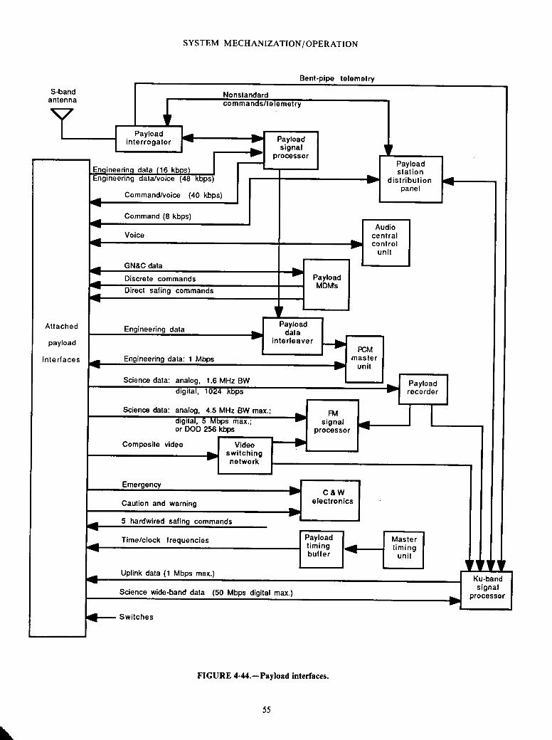
SYSTEM MECHANIZATION/ OPERATION
Bent-pipe telemetry
S-band antenna commanas/telem
Payload interrogator
Command/voice (40 kbps)
Command (8 kbps)
Voice
GN&C data
Discrete commands
Direct sating commands
Payload signal
processorPayload station
distribution panel
Audio central control
unit
Payload MDMs
Attached Engineering data data Payload I
payload interleaver FCMI
interfaces Engineering data: 1 Mbps master unit
Science data: analog, 1.6 MHz BW I Payload digital, 1024 kbps recorder
Science data: analog, 4.5 MHz BW max. FM digital, 5 Mbps max.; signal or DOD 256 kbps processor
video VideoI
Compositeswitching
1mJ network
Emergency I C&w Caution and warning electronics
J 5 hardwired safing commands 1-Time/clock frequencies Payload Master I timing
I
timing buffer unit
Uplink data (1 Mbps max.) 4Science wide-band data (50 Mbps digital max.)
d Switches
FIGURE 4-44.—Payload interfaces.
55
Ku-band signal
processor
k
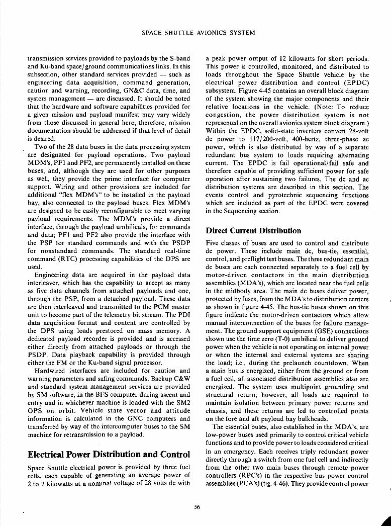
SPACE SHUTTLE AVIONICS SYSTEM
transmission services provided to payloads by the S-band and Ku-band space/ ground communications links. In this subsection, other standard services provided - such as engineering data acquisition, command generation, caution and warning, recording, GN&C data, time, and system management - are discussed. It should be noted that the hardware and software capabilities provided for a given mission and payload manifest may vary widely from those discussed in general here; therefore, mission documentation should be addressed if that level of detail is desired.
Two of the 28 data buses in the data processing system are designated for payload operations. Two payload MDM's, PF1 and PF2, are permanently installed on these buses, and, although they are used for other purposes as well, they provide the prime interface for computer support. Wiring and other provisions are included for additional "flex MDM's" to be installed in the payload bay, also connected to the payload buses. Flex MDM's are designed to be easily reconfigurable to meet varying payload requirements. The MDM's provide a direct interface, through the payload umbilicals, for commands and data; PF1 and PF2 also provide the interface with the PSP for standard commands and with the PSDP for nonstandard commands. The standard real-time command (RTC) processing capabilities of the DPS are used.
Engineering data are acquired in the payload data interleaver, which has the capability to accept as many as five data channels from attached payloads and one, through the PSP, from a detached payload. These data are then interleaved and transmitted to the PCM master unit to become part of the telemetry bit stream. The PDI data acquisition format and content are controlled by the DPS using loads prestored on mass memory. A dedicated payload recorder is provided and is accessed either directly from attached payloads or through the PSDP. Data playback capability is provided through either the FM or the Ku-band signal processor.
Hardwired interfaces are included for caution and warning parameters and safing commands. Backup C&W and standard system management services are provided by SM software, in the BFS computer during ascent and entry and in whichever machine is loaded with the SM2 OPS on orbit. Vehicle state vector and attitude information is calculated in the GNC computers and transferred by way of the intercomputer buses to the SM machine for retransmission to a payload.
Electrical Power Distribution and Control Space Shuttle electrical power is provided by three fuel cells, each capable of generating an average power of 2 to 7 kilowatts at a nominal voltage of 28 volts dc with
a peak power output of 12 kilowatts for short periods. This power is controlled, monitored, and distributed to loads throughout the Space Shuttle vehicle by the electrical power distribution and control (EPDC) subsystem. Figure 4-45 contains an overall block diagram of the system showing the major components and their relative locations in the vehicle. (Note: To reduce congestion, the power distribution system is not represented on the overall avionics system block diagram.) Within the EPDC, solid-state inverters convert 28-volt dc power to 117/200-volt, 400-hertz, three-phase ac power, which is also distributed by way of a separate redundant bus system to loads requiring alternating current. The EPDC is fail operational/ fail safe and therefore capable of providing sufficient power for safe operation after sustaining two failures. The dc and ac distribution systems are described in this section. The events control and pyrotechnic sequencing functions which are included as part of the EPDC were covered in the Sequencing section.
Direct Current Distribution
Five classes of buses are used to control and distribute dc power. These include main dc, bus-tie, essential, control, and preflight test buses. The three redundant main dc buses are each connected separately to a fuel cell by motor-driven contactors in the main distribution assemblies (MDA's), which are located near the fuel cells in the midbody area. The main dc buses deliver power, protected by fuses, from the MDA's to distribution centers as shown in figure 445. The bus-tie buses shown on this figure indicate the motor-driven contactors which allow manual interconnection of the buses for failure manage-ment. The ground support equipment (GSE) connections shown use the time zero (T-0) umbilical to deliver ground power when the vehicle is not operating on internal power or when the internal and external systems are sharing the load; i.e., during the prelaunch countdown. When • main bus is energized, either from the ground or from • fuel cell, all associated distribution assemblies also are energized. The system uses multipoint grounding and structural return; however, all loads are required to maintain isolation between primary power returns and chassis, and these returns are led to controlled points on the fore and aft payload bay bulkheads.
The essential buses, also established in the MDA's, are low-power buses used primarily to control critical vehicle functions and to provide power to loads considered critical in an emergency. Each receives triply redundant power directly through a switch from one fuel cell and indirectly from the other two main buses through remote power controllers (RPC's) in the respective bus power control assemblies (PCA's) (fig. 4-46). They provide control power
56
A
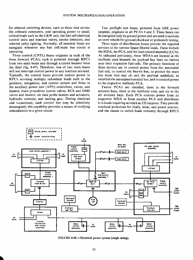
Preflight test bus -4 supply
power test bus
I ac bus I
SYSTEM MECHANIZATION/ OPERATION
for selected switching devices, such as those that service the onboard computers, and operating power to small, critical loads such as the C&W unit, the fuel cell electrical control units and reactant valves, smoke detectors, and selected cabin lighting. Normally, all essential buses are energized whenever any fuel cell/main bus circuit is operating.
Three control (CNTL) buses originate in each of the three forward PCA's; each is powered through RPC's from two main buses and through a circuit breaker from the third (fig. 4-47). Therefore, loss of two main buses will not interrupt control power to any function serviced. Typically, the control buses provide control power to RPC's servicing multiply redundant loads such as the guidance, navigation, and control system and those in the auxiliary power unit (APU) controllers, valves, and heaters; main propulsion system valves; RCS and OMS valves and heaters; air data probe heaters and actuators; hydraulic controls; and landing gear. During checkout and turnaround, each control bus may be selectively deenergized; this capability provides a means of verifying redundancies in a given circuit.
Two preflight test buses, powered from GSE power supplies, originate in aft PCA's 4 and 5. These buses can be energized only by ground power and are used to activate an inert vehicle for ground checkout or prelaunch testing.
Three types of distribution boxes provide the required services to the various Space Shuttle loads. These include the MDA, the PICA, and the load control assembly (LCA). As indicated previously, three MDA's are located in the midbody area beneath the payload bay liner on shelves near their respective fuel cells. The primary functions of these devices are to control power from the associated fuel cell, to control the bus-tie bus, to protect the main bus wires fore and aft and the payload umbilical, to establish the associated essential bus, and to control power to the respective midbody PICA.
Twelve PCA's are installed, three in the forward avionics bays, three in the midbody area, and six in the aft avionics bays. Each PICA receives power from its respective MDA or from another PICA and distributes it to loads requiring as much as 135 amperes. They provide overload protection for loads, wires, and power sources, and the means to switch loads remotely through RPC's
e power - controller
-if- power contactor/relay
dc
loads
I Power I control
dc I Load
7bus
I assembly
____________ ________ I Iloads loads Mid-local i
Idc
dcbus I
Main bus be buses Aft load control
assembly
Mambus 2 Idc
Marn bus 3 I I I I I I loads
I LOA bus I
PowerFtPC Control
assembly I I Forward Main d&c d local dcbus bud c [
I:1-i loads
Fuel
FPC
I nuerter I decoder cell
Main distribution assembly 1
dassembly
supp
c bus I control Power
loadspower dc
APO Tly
Command decoder
Inverter ISc distribution f Motor
and control control loads assembly assembly
Motor ac - I Motor control 111floads control
assembly assembly
ac loads
FIGURE 4-45.—Electrical power system (single string).
57

SPACE SHUTTLE AVIONICS SYSTEM
Main distribution
assembly
To flight deck panels
• I I I I
I I • I • I • I • I
Essential I bus I
I I
I 1BC I
I I
I---------------------I
FIGURE 4-46.—Essential bus distribution (one of three).
or relays. The forward PCA's provide power to the static inverters, which generate ac. Both fore and aft PCA's distribute power to associated LCA's. The aft PCA's - 4, 5, and 6 - also contain motor switches which control ground power.
The LCA's, located in the fore and aft avionics bays, contain hybrid load drivers (HLD's) for control of current loads as great as 5 amperes. The HLD's provide capability for computer control of selected functions.
Alternating Current Generation and Distribution
Each forward avionics bay contains three power static inverter modules, which are connected in a phase-locked array to produce 117/200-volt, 400-hertz, three-phase, y-connected, four-wire ac power. Direct current input power
to drive the inverter arrays is furnished by the respective forward PCA's, which contain circuitry to limit in-rush current to an acceptable level when the highly capacitive inverters are activated. Output current is limited to 20 amperes by circuitry within the inverters. The inverters are synchronized by an internal oscillator.
The output of each three-phase inverter array is monitored and controlled by an inverter distribution and control assembly (IDCA). Relays within the IDCA's connect the inverter arrays to the respective three-phase buses. These relays can be controlled manually by the crew, remotely from the ground during checkout, or automatically by internal circuitry in the event of an overload or an overvoltage. This automatic disconnect feature may be inhibited by the crew during critical mission phases to avoid disconnects caused by spurious signals or transients. Normal C&W monitoring and
58
4

SYSTEM MECHANIZATION! OPERATION
Forward PCA 1 I Onboard or OSE control 1 Control
buses I
RPC
RPC Main A L_.._..J EEI CNTLAB2 I
RPC
r.Forward PCA 2
I Onboard or I GSE control 1 Control
buses
IH RPC Main B L_J
= EEEI f—!J [: 1- Forward PCA 3 I
Onboard or GSE control Control
—=l__ buses
- IcNTLCA1 ---I:i- =
- ......JRPCL -- --1
I Main C L_J _________ - _ CNTLCA2I --u •
RPC CNTLCA3
I --------FIGURE 4-47.—Control buses.
alarms will continue to operate when in the "inhibit" mode.
Each of the three redundant three-phase ac buses is isolated, is capable of supplying nominal power of 2.25 kilovolt-amperes, and is grounded to structure in a single point. All current is confined to the bus wiring except for some navigation equipment which uses an internal chassis ground. No provisions have been made for cross-tying the ac buses to accommodate inverter failures. Power reliability for critical ac loads is obtained either by providing a switch which allows access to more than one bus or by providing duplicate hardware operating off separate buses.
Ten motor control assemblies (MCA's), three each in the fore and aft avionics bays, and four in the midbody area, provide power and control to motors and other three-phase and single-phase loads in the Orbiter.
Approximately 250 three-phase motors are required to drive deployment/ retract mechanisms, latches, actuators, motorized valves, positioning devices, etc. Remote switching capability is provided by three-phase hybrid relays, which can be controlled by MDM commands.
Ground Checkout
The ground launch processing system controls all ground test, checkout, and prelaunch countdown operations until 30 seconds before lift-off, when control is transferred to the Orbiter avionics system. The LPS, however, makes extensive use of the features and capabilities of the onboard avionics system throughout the process. Figure 4-48 shows the major components and interfaces involved. The two MDM's, LA1 and LFI, also known as command decoders, provide interfaces with the vehicle power and subsystem switches and controls necessary for remote activation and operation of the vehicle. The four SRB MDM's perform a similar function. Commands and data requests may be sent to these MDM's on one of the launch data buses by either the LPS or a GPC. Under the protocol established to avoid conflict, however, the GPC's have priority and will assume bus control when activated and loaded with the appropriate vehicle utility software. Under these conditions, the LPS acts as a bus terminal unit and issues commands and data requests through the GPC
Launch data buses
GPC 2
-MDM
IIIIIIIIIIIII1Ii1 Preflight =GPC 3 Ipower and
I subsystem
-SRB switch
GPC4 MDMLL functions l and 2 I
LR -tl 1 and 2
T-O umbilical
Launch processing
system
FIGURE 4-48.—Checkout configuration.
59

SPACE SHUTTLE AVIONICS SYSTEM
in control as part of the polling process. If no GPC is in control, the LPS may assume control of the launch data buses directly.
With the avionics systems powered up and in OPS GNC9, the ground checkout mode, the LPS exercises control through the use of test control supervisor operators. Twenty-six of these have been defined to initiate and control test operations. These can be used
singly or in sequence to cause the GPC's to perform a variety of functions. In addition, they can be used to call a number of test application programs loaded in GPC memory which perform operations excessively compli-cated and otherwise difficult to control by way of the TCS. Examples of prestored routines are the ramp function generator, IMU calibration, the actuator positioning test, and dedicated display checkout.
60
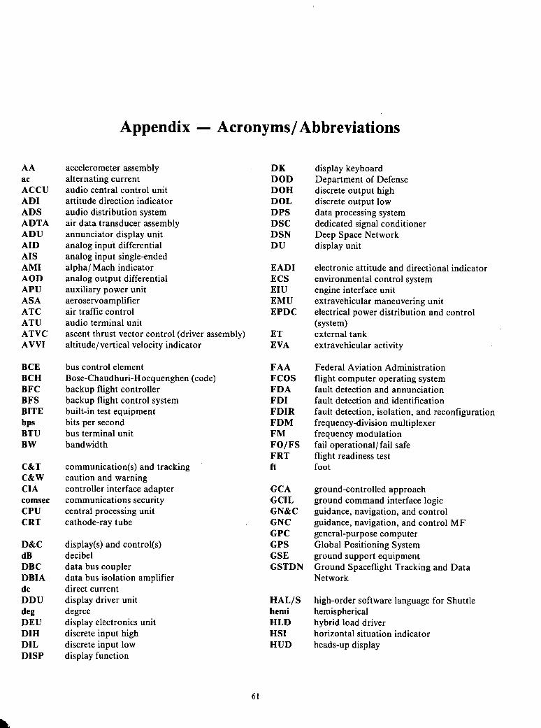
Appendix - Acronyms/ Abbreviations
AA accelerometer assembly DK display keyboard ac alternating current DOD Department of Defense ACCU audio central control unit DOH discrete output high ADI attitude direction indicator DOL discrete output low ADS audio distribution system DPS data processing system ADTA air data transducer assembly DSC dedicated signal conditioner ADU annunciator display unit DSN Deep Space Network AID analog input differential DU display unit AIS analog input single-ended AM! alpha/ Mach indicator EADI electronic attitude and directional indicator AOD analog output differential ECS environmental control system APU auxiliary power unit EIU engine interface unit ASA aeroservoamplifier EMU extravehicular maneuvering unit ATC air traffic control EPDC electrical power distribution and control ATU audio terminal unit (system) ATVC ascent thrust vector control (driver assembly) ET external tank AVVI altitude/ vertical velocity indicator EVA extravehicular activity
BCE bus control element FAA Federal Aviation Administration BCH Bose-Chaudhuri-Hocquenghen (code) FCOS flight computer operating system BFC backup flight controller FDA fault detection and annunciation BFS backup flight control system FDI fault detection and identification BITE built-in test equipment FDIR fault detection, isolation, and reconfiguration bps bits per second FDM frequency-division multiplexer BTU bus terminal unit FM frequency modulation BW bandwidth FO/FS fail operational/ fail safe
FRT flight readiness test C&T communication(s) and tracking ft foot C&W caution and warning CIA controller interface adapter GCA ground-controlled approach comsec communications security GCIL ground command interface logic CPU central processing unit GN&C guidance, navigation, and control CRT cathode-ray tube GNC guidance, navigation, and control MF
GPC general-purpose computer D&C display(s) and control(s) GPS Global Positioning System dB decibel GSE ground support equipment DBC data bus coupler GSTDN Ground Spaceflight Tracking and Data DBIA data bus isolation amplifier Network dc direct current DDU display driver unit HAL/S high-order software language for Shuttle deg degree hemi hemispherical DEU display electronics unit HLD hybrid load driver DIH discrete input high HSI horizontal situation indicator DIL discrete input low HUD heads-up display DISP display function
61
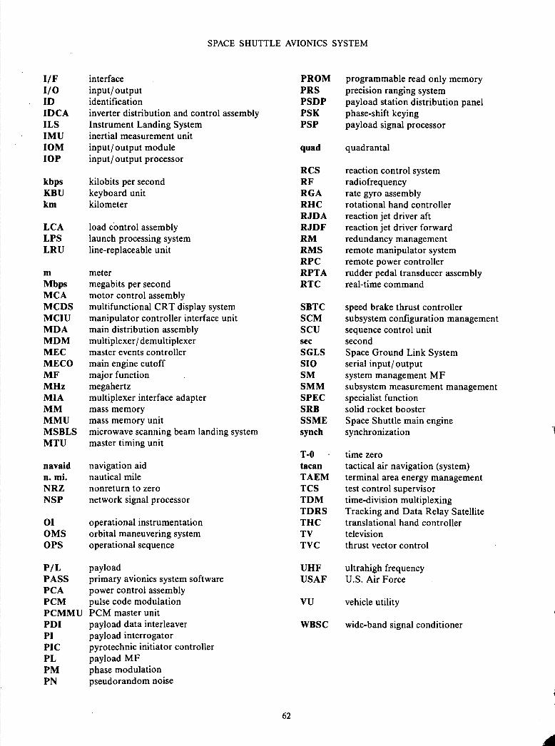
SPACE SHUTTLE AVIONICS SYSTEM
I/F interface PROM programmable read only memory I/O input/output PRS precision ranging system ID identification PSDP payload station distribution panel IDCA inverter distribution and control assembly PSK phase-shift keying ILS Instrument Landing System PSP payload signal processor IMU inertial measurement unit IOM input/output module quad quadrantal lOP input/output processor
RCS reaction control system kbps kilobits per second RF radiofrequency KBU keyboard unit RGA rate gyro assembly km kilometer RHC rotational hand controller
RJDA reaction jet driver aft LCA load control assembly RJDF reaction jet driver forward LPS launch processing system RM redundancy management LRU line-replaceable unit RMS remote manipulator system
RPC remote power controller m meter RPTA rudder pedal transducer assembly Mbps megabits per second RTC real-time command MCA motor control assembly MCDS multifunctional CRT display system SBTC speed brake thrust controller MCIU manipulator controller interface unit SCM subsystem configuration management MDA main distribution assembly SCU sequence control unit MDM multiplexer/demultiplexer sec second MEC master events controller SGLS Space Ground Link System MECO main engine cutoff 510 serial input/output MF major function SM system management MF MHz megahertz SMM subsystem measurement management MIA multiplexer interface adapter SPEC specialist function MM mass memory SRB solid rocket booster MMU mass memory unit SSME Space Shuttle main engine MSBLS microwave scanning beam landing system synch synchronization MTU master timing unit
T-O time zero navaid navigation aid tacan tactical air navigation (system) n. ml. nautical mile TAEM terminal area energy management NRZ nonreturn to zero TCS test control supervisor NSP network signal processor TDM time-division multiplexing
TDRS Tracking and Data Relay Satellite 01 operational instrumentation THC translational hand controller OMS orbital maneuvering system TV television OPS operational sequence TVC thrust vector control
P/L payload UHF ultrahigh frequency PASS primary avionics system software USAF U.S. Air Force PCA power control assembly PCM pulse code modulation VU vehicle utility PCMMU PCM master unit PD! payload data interleaver WBSC wide-band signal conditioner P1 payload interrogator PlC pyrotechnic initiator controller PL payload MF PM phase modulation PN pseudorandom noise
62

See Oversized Document (Attached to the end of this document)
US ARMY (Defense Ammunition Center, McAlester, OK) DocumentATM Form ID 082209DAC004

119