Embed Size (px)
Citation preview

Degenerate Motions in Multicamera Cluster SLAM with
Non-overlapping Fields of View
Michael J. Triboua,∗, David W. L. Wangb, Steven L. Waslanderc
aAeryon Labs Inc., 575 Kumpf Drive, Waterloo, ON, Canada, N2V 1K3.bDepartment of Electrical and Computer Engineering, University of Waterloo, 200
University Avenue West, Waterloo, ON, Canada, N2L 3G1.cDepartment of Mechanical and Mechatronics Engineering, University of Waterloo, 200
University Avenue West, Waterloo, ON, Canada, N2L 3G1.
Abstract
An analysis of the relative motion and point feature model configurationsleading to solution degeneracy is presented, for the case of a Simultane-ous Localization and Mapping system using multicamera clusters with non-overlapping fields-of-view. The SLAM optimization system seeks to minimizeimage space reprojection error and is formulated for a cluster containingany number of component cameras, observing any number of point featuresover two keyframes. The measurement Jacobian is transformed to exposea reduced-dimension representation such that the degeneracy of the systemcan be determined by the rank of a dense submatrix. A set of relative mo-tions sufficient for degeneracy are identified for certain cluster configurations,independent of target model geometry. Furthermore, it is shown that increas-ing the number of cameras within the cluster and observing features acrossdifferent cameras over the two keyframes reduces the size of the degeneratemotion sets significantly.
Keywords: SLAM, Computer vision, Multicamera cluster,Non-overlapping FOV, Degeneracy analysis, Critical motions
∗Corresponding author at: Aeryon Labs Inc., 575 Kumpf Drive, Waterloo, ON, Canada,N2V 1K3. Telephone: +1-519-635-8971
Email addresses: [email protected] (Michael J. Tribou), [email protected](David W. L. Wang), [email protected] (Steven L. Waslander)
Preprint submitted to Image and Vision Computing September 19, 2015
1. Introduction
Precise robotic motion and manipulation tasks with respect to unknowntarget environments and objects require an accurate, real-time measurementof the relative position and orientation of the robot and target. Multicamerasystems are often employed for robotic pose and target model estimation, aseach camera is an inexpensive, light-weight, and passive device capable ofcollecting a large amount of environment information at high rates. Manyresearchers across different fields have investigated the use of cameras forthe purpose of estimating motion and scene structure. As a result, manytechniques using a variety of camera types and configurations have beendetailed in the literature.
A camera cluster is composed of any number of simple perspective cam-eras mounted rigidly with respect to each other, as shown in Figure 1, includ-ing configurations in which their fields-of-view (FOV) are spatially disjoint[1]. This arrangement makes effective use of the camera sensors to cover alarge combined FOV with high resolution, and in general, is able to overcomethe limitations of other camera configurations, such as scale and translation-rotation motion ambiguities [2]. Additionally, by arranging the cameras tolook in many directions, the pose estimation is made more robust since whencertain cameras do not see any point features suitable for tracking, the othercameras in the cluster can maintain the localization. In this scenario, cam-era arrangements with a smaller collective FOV may become lost causingthe tracking operation to fail. Several multicamera cluster Simultaneous Lo-calization and Mapping (SLAM) [3] algorithms have been proposed in theliterature (e.g. [4, 5, 6]).{II-5}
Figure 1: An example camera cluster in which the three component camerasare rigidly-fixed with respect to each other.
2

In order for any pose estimation system to operate successfully, the cur-rent state must be uniquely recoverable given the measurable outputs up to,and including the current time step. In the context of a multicamera clusterrelative pose system, this means that the image measurements must containsufficient information to recover the cluster motion and the target model pa-rameters, including the proper global scale metric. Within the SLAM system,the quality of the motion and structure parameter estimates are fundamen-tally linked. Further the convergence properties and accuracy of the solutiondepends on the point feature constellation geometry and relative motion tra-jectory of the camera cluster and target during the estimation. Identifyingand avoiding configurations where a solution is difficult to recover is vital tosuccessful application to robotics operations.{II-1}
Furthermore, the solution must be unique since convergence to a differentconfiguration, which may also agree with the measurements, would likelyresult in failure of perception and control operations. The visual SLAMsystem can be considered as a physical mechanism with the geometry andlinks represented in the parametrization. For the solution to converge to aunique configuration, it must be sufficiently constrained by the bearings-onlyimage measurements or the mechanical system is not rigid and the solutioncan move without violating these constraints.{II-1}
When the multicamera cluster is configured such that there is little or nospatial FOV overlap between the component cameras, the sensitivity of theimage measurements to the global scale of the reconstructed model is low,particularly around specific motion profiles known as critical motions [7].When the relative motion of the cluster is at or near critical, the global scale ofthe solution is extremely difficult, if not impossible, to recover accurately. Inthe presence of measurement noise, the solution will converge to an incorrectscale value. If the motion and structure estimates are used in a control loop,the incorrect scale could result in inefficient or unstable behaviour.{II-1}
This work investigates the degenerate configurations when estimating theSLAM system states for a calibrated multicamera cluster over two keyframeswhile observing a set of point features in each camera and using an iterativeoptimization or recursive filter-based approach, minimizing the image spacereprojection error of point feature measurements. This includes Bundle Ad-justment (BA) [8] schemes as well as recursive filters such as an extendedKalman filter [9]. The main contribution is the identification of configura-tions of motion and target model structure leading to non-unique SLAMsolutions.
3

Determining the system configurations leading to solution degeneracy isclosely related to the concept of observability in control systems. In thestudy of observability for nonlinear systems, the local weak observability ofthe system can be determined by calculating the observability rank conditionabout any point in the state space [10]. This involves checking the columnrank of a matrix containing the partial derivatives with respect to the systemstates, for increasing orders of Lie derivatives of the measurement model withrespect the the system dynamics. When the matrix has full column rank,the system is locally weakly observable about that point.
For a SLAM system using only the visual measurements from the clustercameras and a non-stationary target, the system does not have a model ofthe dynamics for the relative motion and therefore, only the zeroth-orderLie derivatives are non-zero. In this case, evaluating the observability rankcondition is equivalent to checking the rank of the measurement Jacobianmatrix, as will be done here in the degeneracy analysis in Section 4. If thesystem were to contain a model of the relative motion dynamics, and theextra information that comes with it, the higher-order Lie derivatives of themeasurement model would contain non-zero terms and the added matrix rowswould only increase the likelihood that the matrix has full column rank at anypoint in the state space. However, in this analysis, no such assumptions aboutthe relative motion dynamics are made and the degenerate configurationsarising from only using image measurements for a set of point features overtwo keyframes are identified.
The remainder of this paper is arranged as follows: Section 2 contains areview of the previous analyses for degenerate configurations of the multicam-era cluster relative pose system; Section 3 presents the multicamera clusterSLAM system; the degenerate configurations of the pose estimation systemare identified in Section 4; and finally, conclusions are drawn in Section 5.
2. Related Work
Previous analyses identifying cluster motions leading to degenerate sys-tem solutions have assumed that the five degrees of freedom describing rel-ative orientation and translation direction of the cluster are known usingthe well-studied single camera ego-motion estimation techniques (e.g. [8]).These include the work of Kim et al. [11], and Clipp et al. [7] for cameraclusters with two component cameras, as well as that of the authors [12]for clusters with three component cameras. Of interest are the conditions
4

when the image measurements from the camera cluster are able to allow forestimation of the final degree of freedom, corresponding to the translationmagnitude and therefore, global system scale. The analyses show that wheneach point feature is seen by only one of the two cameras at both keyframes,the global scale of the solution solution is recoverable only when the relativetranslational and rotational motion are both non-zero, and does not resultin the optical centres of each camera moving in concentric arcs on circleswith a common centre at the intersection of the baselines at each keyframe[7]. When a third non-collinear camera is added to the cluster, the set ofdegenerate motions is reduced to those which result in all the three camerasmoving in parallel [12].
Analyses of degeneracies of the full SLAM solution for multicamera clus-ters have focused on those associated with solving the generalized camerarelative pose problem, either linearly using the Generalized Essential Matrix(GEM) [2], or aligning imaging rays in space for minimal cases of cameraposes and points [13]. Sturm [14], Stewenius et al. [13], and Mouragnon et
al. [15] discuss some degenerate cases, but Kim and Kanade [16] provide themost complete analysis. They identify the following degenerate configura-tions for generalized cameras using the seventeen point method [2]:
1. All of the observation rays pass through one common point before andafter the camera motion.
2. The camera centres are on a line before and after the motion.
3. Each corresponding ray pair passes through the same local point in thegeneral camera frame before and after the motion.
For a camera cluster with non-overlapping FOV, it is possible that eachcomponent camera observes its own mutually exclusive set of feature pointsover the two keyframes. In this case, the system satisfies condition 3 andthe solution to the seventeen point algorithm is always degenerate. How-ever, it is known from previous results that in certain configurations, othersolution methods are able to recover an accurate estimate of the motion andstructure. Consequently, the seventeen point algorithm does not always re-cover a solution when one exists. This problem was noticed by Li et al. [17],who have since modified the algorithm for use with non-overlapping clusters,but the subsequent degeneracy analysis has not been carried out. More im-portantly, the degenerate configurations are specific to the linear method ofestimation. In this work, the minimization of image-space reprojection error
5
is considered and the configurations for which an optimization of this typewill fail are identified in the subsequent analysis.
3. Multicamera Cluster Pose Estimation
3.1. Pin-hole Camera Model
An individual component camera within the cluster is modelled as asimple pin-hole imaging device, which maps 3D points onto a 2D planecalled the image plane [18]. An example is shown in Figure 2. A 3D point
pCi =[xCi yCi zCi 1
]⊤, represented in the projective space P
3 (refer to
Appendix A for a brief introduction){I-4}, and expressed with respect to theith camera coordinate frame, Ci, is projected onto the image plane Ii. Theintersection of the point feature ray pCi , through the optical centre, oi, with
the image plane occurs at the point,[u v
]⊤∈ R
2. It is assumed that eachcamera has been intrinsically calibrated using one of the many existing offlinetechniques [8], such that the measurements are made to match the structureshown.
optical axis
optical centreimage plane
Figure 2: A simple pin-hole camera measurement model is used to relatethe camera frame coordinates to the camera image plane coordinates for afeature point.
The camera projection matrix, κi, maps the point in P3 into P
2 on theimage plane. It is assumed in this work, without loss of generality, that the
6

projection matrices for all of the cameras have the form,
κi =
−1 0 0 00 −1 0 00 0 1 0
. (1)
The point pCi is projected into P2 on the image plane,
pIi = κipCi , (2)
then subsequently mapped to the actual image plane coordinates in R2
through the demotion function π2 for P2,
π2(pIi) =
[u
v
]
=
−xCi
zCi
−yCi
zCi
, zCi 6= 0. (3)
Each camera is assumed to have an FOV strictly less than 180 degreesand therefore, is only able to observe points in front of the lens so every pointis constrained to have a positive z-axis coordinate,
zCi > 0, (4)
which satisfies (3).
3.2. Calibrated Multicamera Cluster
Collectively, the calibrated camera cluster is modelled as a set of nc com-ponent pin-hole cameras with known relative coordinate transformations be-tween each camera coordinate frame. Accordingly, a point pCh in the cameraframe Ch, can be transformed into any other camera frame Ci by,
pCi = TCi
ChpCh (5)
where TCi
Ch∈ SE(3), ∀i, h ∈ {1, . . . , nc}, is a homogeneous transformation
matrix{I-6} [19]. Without loss of generality, the coordinate frame for thecamera cluster is chosen to coincide with the first camera frame, C1. Thetransformation from camera h to the cluster frame can be written in short-ened form as TCh
≡ TC1Ch, where the cluster frame C1 is implied when the
superscript is neglected. The transformation is shown in Figure 3.
7

Figure 3: The relative position and orientation of each camera is knownrelative to the cluster frame, C1 and therefore, the position of points in anycamera frame can be found with respect to the cluster frame using the knowntransformation, TCh
.
3.3. Point Feature Target Object Model
The tracked target object or environment, henceforth referred to simplyas the target, is a rigid body which contains a set of visible point features. Apoint feature is a visually distinguishable point on the tracked physical targetthat corresponds to a unique 3D position in a local target coordinate frameM , and is measurable in a set of camera images through a relative motionsequence. Image measurements of these point features are extracted fromthe images using image processing techniques, including feature extractionalgorithms like the FAST corner detector [20, 21], the Scale-Invariant FeatureTransform (SIFT) [22], or Speeded-Up Robust Features (SURF) [23].
The target model point features are organized into nk keyframes, each asix degree of freedom pose with respect to the target model reference frameM , along with the nc images from the cluster cameras captured at thatlocation, as in [24] for a single camera. The coordinate frame of camera h atkeyframe k is denoted ChKk.
Since the relative position and orientation of each camera within the clus-ter is fixed at all times, the kth keyframe pose is parameterized by the singlehomogeneous transformation for the cluster coordinate frame at the key-frame, C1Kk, with respect to the target model reference frame, M , resultingin TM
C1Kk∈ SE(3). The C1 and M frames are applied universally in this
keyframe pose definition, and therefore, the transformation will be writtensimply as TKk
≡ TMC1Kk
. The pose of camera h at keyframe k is easily found
8

as,
TMChKk
= TKkTCh
. (6)
The position of the jth point feature is parameterized by the azimuth andaltitude angles of the vector from the origin of the anchor camera coordinateframe through the feature, µj = [φj, θj ]
⊤ where φj, θj ∈(−π
2, π2
). The depth
along this bearing to the point feature, is the value sj ∈ R+. The bearing
angles are used to form the unit vector in the camera coordinate frame atthe first keyframe,
ph,1j =
sinφj cos θj− sin θj
cosφj cos θj
, (7)
and the point feature position is along this bearing at the distance sj,
ph,1j = sjp
h,1j . (8)
The separation of the bearing and range parameters for the point featurecoordinates in this parameterization allows for isolating the components ofthe point position that are readily determined. Since the cameras are bearing-only measurement devices, the bearing to each point feature is found fromonly one observation. However, the range to the point must be triangulatedover multiple observations. This parameterization is similar to the InverseDepth Parameterization (IDP) by Civera et al. [25].{I-7}
An example system with a camera cluster composed of nc = 2 cameras isshown in Figure 4. The cameras in this example are arranged back-to-backwith the optical axes looking outwards along the green axes of the associatedcoordinate frames. The jth point feature is anchored in the second cameraat the first keyframe, C2K1, and its position with respect to this coordinateframe is represented as p2,1
j .The parameters representing the poses of the keyframes, together with
the positions of the point features observed within them, compose the targetmodel, as well as the full system state. These parameters are estimated usingthe point feature image measurements within the cluster cameras.
3.4. Multicamera Cluster SLAM System
This work considers the motion and structure estimation for a clusterof nc cameras observing a set of nf point features over two keyframes. The
9

initial pose
and keyframe
second
keyframe
Figure 4: An example target object model with two keyframes for a two-camera back-to-back cluster. The cameras look outwards with the greenarrows showing the optical axes. The point feature j is anchored, and there-fore, positioned within the C2K1 coordinate frame. The relative pose ofcamera 2, TC2 , is known from calibration, but the relative pose of keyframe2, TK2 , as well as the position of the point features must be estimated.
cameras within the cluster are arranged with little or no overlap in their FOVwhere each point feature in the target model is visible in only one cameraat the first keyframe. Without loss of generality, the target model frameis chosen to coincide with the pose of the first keyframe M ≡ C1K1. Thisresults in the keyframe transformation becoming the identity,
TK1 = I4×4. (9)
Several further assumptions about the system are made to facilitate theanalysis in the subsequent sections:
Assumption 3.1. Each point feature is observed and measured by only oneof the component cameras at the first keyframe. The position of the pointfeature is expressed with respect to the coordinate frame for that cameraat the first keyframe. The coordinate frame in which the point feature isparameterized is referred to as the anchor keyframe and camera coordinateframe.
10

Assumption 3.2. Each point feature is observed and measured by one ormore of the component cameras at the second keyframe. At least one of theobservations is by a camera for which its motion is not collinear with theinitial bearing to the point feature at the first keyframe. The camera andkeyframe in which the observation occurs is called the observing keyframeand camera coordinate frame.
Assumption 3.3. The point feature positions and keyframe poses are ar-ranged such that if a camera observes a point feature, the feature positionexpressed in the observing camera coordinate frame has a finite positive non-zero z-axis component, 0 < z < ∞.
For Assumption 3.1, the function h : {1, . . . , nf} → {1, . . . , nc} maps thepoint feature index to the anchor camera index. As a result, the anchorcamera for the jth point feature is camera h(j). In the following, when itis obvious from the context, the anchor camera index will be written in theshortened-form by dropping the argument, h ≡ h(j).
Similarly for Assumption 3.2, the jth point feature is observed and mea-sured by no(j) ∈ N
+ cameras at the second keyframe. The indices of the ob-serving cameras are found using the function i : {1, . . . , nf}×{1, . . . , no(j)} →{1, . . . , nc}, such that the kth observation of the jth point feature at the secondkeyframe is measured by camera i(j, k). Once again, this will be shortenedto exclude the feature index j and observation index k when it is implied bythe context, i ≡ i(k) ≡ i(j, k).
The motion of the camera cluster between the two keyframes is param-eterized by six values describing the relative translation and orientation ofthe first keyframe with respect to the second keyframe. The translation pa-rameters, tx, ty, tz, form the relative translation vector, tK = [tx, ty, tz]
⊤,
and the angle-axis rotation parameters, ωK = [ωx, ωy, ωz]⊤, form the relative
rotation matrix, RK ∈ SO(3), using the Rodrigues’ rotation formula [8]{I-2}.Together, the rotation and translation form the transformation, TK ∈ SE(3).
The resulting state vector, x ∈ Rn, where n = 6 + 3nf , is composed of
the parameters for the nf point features, along with the relative translationand orientation states for the cluster motion between the keyframes,
x =
x1
x2
x3
, (10)
11

where
x1 = [s1, . . . , snf]⊤ ∈ R
nf
+ , (11)
are the radial distances to the point features,
x2 = [tK⊤,ωK
⊤]⊤∈ R
6, (12)
are the relative position and orientation of the first keyframe with respect tothe second keyframe and,
x3 = [µ1⊤,µ2
⊤, . . . ,µnf
⊤]⊤∈ R
2nf , (13)
are the bearings to the point features in their respective anchor camera co-ordinate frames. This state order has been specifically chosen in order tofacilitate the analysis of the degeneracies of the solution presented in Section4.
3.5. Camera Cluster Measurement Model
The system measurement vector, z ∈ Rm, is formed by stacking the image
plane coordinates of all of the point feature observations in all cameras atboth keyframes, where m = 2(nf +mo) with
mo =
nf∑
j=1
no(j), (14)
as the total number of observations of all of the point features at the secondkeyframe.
The measurement model, relating the observed point feature locations inthe camera image planes, to the system states, can be written as a series ofcoordinate transformations. Suppose that the jth point feature, anchored inthe coordinate frame ChK1, is measured by camera i at CiK2. An exampleof this chain of transformations is shown for the simple back-to-back two-camera cluster system in Figure 4. In this particular case, the point featurej is anchored in C2K1 and observed in C2K2.
The point feature position parameters give the location of the jth featurein its anchor keyframe and camera frame ChK1, resulting in p
h,1j . This point
feature is first transformed into the target model coordinate frame by,
pMj = TK1TCh
ph,1j (15)
= TChph,1j , (16)
12

which is the transformation provided by the known cluster calibration.The point feature position, with position estimate expressed in the tar-
get model reference frame, is transformed into the coordinate frame of theobserving keyframe and camera CiKℓ using the relative keyframe pose trans-formation, TKℓ
, and the cluster calibration,
pi,ℓj =
[
xi,ℓj y
i,ℓj z
i,ℓj 1
]⊤(17)
= (TCi)−1(TKℓ
)−1pMj (18)
= (TCi)−1(TKℓ
)−1TCh
ph,1j . (19)
Finally, the point is projected into P2 and onto the image plane of camera
Ci using the corresponding projection matrix, κi,
ui,ℓj =
[ux uy uz
]⊤(20)
= κipi,ℓj (21)
=
−xi,ℓj
−yi,ℓj
zi,ℓj
, (22)
which leads to the resulting measurement vector zi,ℓj ∈ R
2 and mapping
gi,ℓj : Rn → R
2 for the observation of point feature j in camera i at keyframeℓ,
zi,ℓj = g
i,ℓj (x) = π2
(
ui,ℓj
)
. (23)
Each of the intermediate transformations in (19) can be represented by arotation matrix and translation vector,
TCh=
[RCh
tCh
01×3 1
]
(24)
TKℓ=
[RKℓ
tKℓ
01×3 1
]
=
I4×4, ℓ = 1[
R⊤K −R
⊤KtK
01×3 1
]
, ℓ = 2(25)
TCi=
[RCi
tCi
01×3 1
]
. (26)
13

When (24)–(26) are substituted into (19) along with (8), the coordinates ofthe point feature position in R
3 become,
pi,ℓj = sjR
⊤CiR
⊤KℓRCh
ph,1j −R
⊤CiR
⊤KℓtKℓ
+R⊤CiR
⊤KℓtCh
−R⊤CitCi
(27)
= R⊤Ci
(
sjR⊤KℓRCh
ph,1j −R
⊤KℓtKℓ
+R⊤KℓtCh
− tCi
)
(28)
= R⊤Ciqi,ℓj , (29)
where
qi,ℓj = sjaj,ℓ + bℓ + ch,ℓ + di (30)
with
aj,ℓ = R⊤KℓRCh
ph,1j (31)
bℓ = −R⊤KℓtKℓ
(32)
ch,ℓ = R⊤KℓtCh
(33)
di = −tCi(34)
and
RCi=[ni,x ni,y ni,z
]∈ SO(3), (35)
where ni,x, ni,y, and ni,z are the orthonormal basis vectors for the observingcamera i frame with respect to the camera 1 coordinate frame. An examplesystem consisting of the cameras observing point features over two keyframesis shown in Figure 5 with the intermediate variables labelled.
The set of camera observation vectors for point feature j is defined asthe displacements between the anchor camera coordinate frame at the firstkeyframe, ChK1, and the centres of each of the observing cameras at thesecond keyframe, Ci(k)K2, ∀k ∈ {1, . . . , no(j)}. The set of vectors are,
V = {vα,β ∈ R3|α, β ∈ N
+, α ≤ nf and β ≤ no(α)}. (36)
Therefore, if it is included in the set V , the camera observation vector canbe written as,
vα,β = b2 + ch(α),2 + di(β). (37)
and is illustrated in the example system shown in Figure 6.
14

Figure 5: An example three-camera cluster observing point features overtwo keyframes with intermediate vectors labelled. Vectors are parameterizedwith reference to keyframe C1K2.
The image coordinates of each individual point feature observation mea-surements are then compiled into a vector for point feature j containing allof the individual observations of that feature at both keyframes,
zj =
zi(1),2j...
zi(no),2j
zh,1j
∈ R
2+2no , (38)
where no ≡ no(j)> 0{I-8} is the number of observations of the jth point featureat the second keyframe.
The full system measurement vector is composed of the observations of
15

Figure 6: An example two-camera cluster observing three features. Eachfeature is observed in one camera at the first keyframe, but some are seen bydifferent cameras at the second keyframe. The camera observation vectors,v1,1, v2,2, v3,1 link the cameras which see the same feature at the differentkeyframes.
the nf point features at both keyframes,
z =
z1...
znf
∈ R
m. (39)
4. Degeneracy Analysis
In this section, degenerate configurations of relative cluster motion andtarget model point feature geometry are analysed for the multicamera clusterSLAM system. Whether or not the system measurement Jacobian J is fullrank, is shown to be determined by whether the dense sub-matrix M2 is fullrank. This matrix is a function of both the relative cluster motion and targetmodel geometry. Therefore, the degenerate configurations of the system arethose for which rank (M2) < 6.
Furthermore, a set of cluster relative motions that are sufficient for solu-tion degeneracy are identified. This subset of the degenerate configurationsdepends only on the relative motion and is independent of the point featureconstellation.
16
Finally, some example systems are analysed numerically to offer insightinto the complete necessary and sufficient set of degenerate configurations.Though not exhaustive, they serve to demonstrate the decreasing degen-erate set size when adding more point feature observations to the SLAMsystem.{I-1}
4.1. Solution Degeneracies
Typical optimization methods attempt to minimize a nonlinear cost func-tion, c : Rn → R, and determine the optimal state vector estimate, x∗ ∈ R
n,such that,
x∗ = argminx
c(x). (40)
The optimization proceeds iteratively, starting with an initial state estimate,x0 ∈ R
n. Each iteration seeks to update the current state estimate, xk, witha vector δk ∈ R
n,
xk+1 = xk + δk, (41)
such that the sequence {x0, x1, x2, . . . } → x∗. In this analysis, a cost functionrelating to sum of squared measurement error is assumed,
c(xk) =1
2z⊤k zk, (42)
where zk = z− g(xk) ∈ Rm is the measurement error vector at iteration k.
Commonly-used optimization algorithms include the Levenberg-Marquardt(LM) method [8], Gauss-Newton, gradient descent, or Newton step.{I-9} Eachof these optimization methods can operate using the sum of squared repro-jection error and the parameter update δk is defined as the solution to,
Nδk = J⊤zk (43)
where N is the normal matrix, which varies by optimization method, and J
is the measurement Jacobian such that,
J =∂g(x)
∂x
∣∣∣∣x=xk
∈ Rm×n. (44)
Solving for δk, the solution becomes,
δk = N−1J⊤zk, (45)
17

where zk = z−g(xk) is the measurement error. A unique δk can be found aslong as the matrix N is invertible and the Jacobian has full rank. Therefore,the system in (43) is degenerate when,
rank (J) < n, (46)
and the solution is under-constrained. The cases where the system becomesdegenerate are the focus of this work and are investigated in the next section.
4.2. Identification of Degenerate Configurations
This section identifies the configurations of the camera cluster geometry,relative motion, and target model structure, for which the Jacobian J fallsbelow full column rank. It is shown that for the assumptions stated previ-ously, the m× n measurement Jacobian matrix J has full rank if and only ifa mo × 6 matrix, M2 has full rank.
To determine the rank of the Jacobian matrix, the structure of the sub-blocks formed for the point feature observations is investigated. Each pointfeature j is observed by only one camera at the first keyframe. This obser-vation adds two rows to the Jacobian,
Jh,1j =
∂gh,1j (x)
∂x
∣∣∣∣∣x=x
(47)
=
[
02×nf+6 02×2(j−1)
∂gh,1j (x)
∂µj
∣∣∣∣∣x=x
02×2(nf−j)
]
, (48)
where the only non-zero elements are in the 2 × 2 block relating the mea-surement coordinates to the point feature bearing states,
∂gh,1j (x)
∂µj
∣∣∣∣∣x=x
=
− tan(φj)2 − 1 0
tan(φj) tan(θj)
cos(φj)
1
cos(φj) cos(θj)2
. (49)
The non-zero element structure of these rows are shown in Figure 7.Each point feature j is also observed and measured by at least one camera
at the second keyframe. The Jacobian matrix rows corresponding to the kth
observation of point feature j in the second keyframe with camera i(k) are
18

Figure 7: Structure of the Jacobian rows for the measurement of the pointfeature j in its anchor camera at the first keyframe. Non-zero elements areshown as the shaded cells. The columns not related to feature j contain onlyzeros and have been removed for conciseness.
the partial derivatives of the measurement equation (23) with respect to thesystem states,
Ji(k),2j =
∂gi(k),2j (x)
∂x
∣∣∣∣∣x=x
, (50)
=
∂π2
(
ui(k),2j
)
∂ui(k),2j
∣∣∣∣∣∣x=x
(
∂ui(k),2j
∂x
∣∣∣∣∣x=x
)
, (51)
using the chain rule. Dropping the implied x = x, the first term evaluatesto,
∂π2
(
ui(k),2j
)
∂ui(k),2j
=1
(uz)2
[uz 0 −ux
0 uz −uy
]
(52)
=1
(
zi(k),2j
)2
[0 −1 01 0 0
] [
ui(k),2j
]
×, (53)
where [a]× is the skew-symmetric matrix such that [a]× b = a×b, ∀a,b ∈ R3.
Substituting (53) back into (51) and recognizing that,
ui(k),2j =
−1 0 00 −1 00 0 1
R⊤Ci(k)
qi(k),2j , (54)
19

the Jacobian rows can be written as,
Ji(k),2j =
1(
zi(k),2j
)2
[0 1 0−1 0 0
] [
ui(k),2j
]
×
∂ui(k),2j
∂x, (55)
=1
(
zi(k),2j
)2
[0 −1 01 0 0
]
R⊤Ci(k)
[
qi(k),2j
]
×
∂qi(k),2j
∂x, (56)
=1
(
zi(k),2j
)2
−(
ni(k),y × qi(k),2j
)⊤
(
ni(k),x × qi(k),2j
)⊤
∂qi(k),2j
∂x, (57)
where the partial derivatives of the point feature position at the second key-frame with respect to the system states are written,
∂qi(k),2j
∂x=
[
03×(j−1)
∂qi(k),2j
∂sj03×(nf−j)
∂qi(k),2j
∂tK
∂qi(k),2j
∂ωK
03×2(j−1)
∂qi(k),2j
∂µj
03×2(nf−j)
]
(58)
with the position change with respect to the radial distance,
∂qi(k),2j
∂sj= aj,2, (59)
the translation between the keyframes,
∂qi(k),2j
∂tK= I3×3, (60)
the rotation between the keyframes,
∂qi(k),2j
∂ωK
= − [sjaj,2 + ch,2]× , (61)
and the initial bearings to the point feature,
∂qi(k),2j
∂µj
= sjRKRCh
cosφj cos θj − sinφj sin θj0 − cos θj
− sinφj cos θj − cosφj sin θj
. (62)
20

Figure 8: Structure of the Jacobian rows for an observation of the pointfeature j at the second keyframe.
The structure of the Jacobian rows associated with the observations of pointfeature j at the second keyframe is shown in Figure 8.
The full measurement Jacobian is formed by stacking all of the observa-tions of all of the point features at both keyframes,
J =
Ji(1,1),21...
Ji(1,no(1)),21
Jh(1),11
...
Ji(nf ,1),2nf
...
Ji(nf ,no(nf )),2nf
Jh(nf ),1nf
. (63)
The configurations for which this measurement Jacobian possesses fullrank can be identified by checking the rank of a reduced-dimension matrix,as shown in the following Lemma.
Lemma 4.1. For a multicamera cluster SLAM system satisfying Assump-
tions 3.1, 3.2, and 3.3, the rank of the measurement Jacobian matrix J in
21

(63) is full if and only if the rank of the matrix,
M2 =
−a⊤1,2 [v1,1]× a⊤
1,2 [v1,1]× [w1]×...
...
−a⊤1,2
[v1,no(1)
]
×a⊤1,2
[v1,no(1)
]
×[w1]×
...
−a⊤nf ,2
[vnf ,1
]
×a⊤nf ,2
[vnf ,1
]
×
[wnf
]
×...
...
−a⊤nf ,2
[vnf ,no(nf )
]
×a⊤nf ,2
[vnf ,no(nf )
]
×
[wnf
]
×
, (64)
where
wj = sjaj,2 + ch(j),2,
is full.
Proof. The strategy is to first show that the columns of J correspondingto the point feature positions (sj, µj) have full rank. Consequently, theonly way for the Jacobian to have less than full rank is when the columnscorresponding to the keyframe motion (tK , RK) have rank less than six.
By Assumption 3.3, the position of the jth point feature in its anchorcamera and keyframe ensures that cos(φj) > 0 and cos(θj) > 0. As a result,the block (49) always has a rank of 2 since the determinant is non-zero,
det
(
∂gh,1j (x)
∂µj
∣∣∣∣∣x=x
)
=−1
cos(φj)3 cos(θj)26= 0. (65)
Therefore, it is possible to diagonalize the sub-block using elementary rowand column operations without changing the rank of the matrix. After diago-nalization, the new matrix rows, Kh,1
j , have the structure shown in Figure 9.As a result, the columns corresponding to the bearing states µj have fullrank for all of the point features.
Additionally, the columns associated with the point feature radial depthparameter sj for an observation at the second keyframe contain only zeroswhen,
[−n⊤
i(k),y
n⊤i(k),x
]
[vj,k]× aj,2 = 02×1, (66)
22

Figure 9: Structure of the Jacobian rows for the measurement of the pointfeature j in the first keyframe after diagonalizing the bearing sub-block.
the displacement between the anchor and observing camera coordinate framesis collinear with the initial bearing to the point feature in the anchor cam-era frame. In this case, there is no information about the depth of thefeature within this measurement since the triangulation baseline has zerolength. However, by Assumptions 3.2 and 3.3, there exists an observationk ∈ {1, . . . , no(j)} such that,
[sxsy
]
=
[−n⊤
i(k),y
n⊤i(k),x
]
[vj,k]× aj,2 6= 02×1, (67)
and therefore, at least one non-zero element in the column. The matrix rowsJi(k),2j are manipulated using the row operations matrix,
Oi(k),2j =
n⊤i(k),x
[
qi(k),2j
]
×aj,2 0
−n⊤i(k),x
[
qi(k),2j
]
×aj,2 −n⊤
i(k),y
[
qi(k),2j
]
×aj,2
, if sx, sy 6= 0
0 1
n⊤i(k),x
[
qi(k),2j
]
×aj,2 0
, if sx = 0, sy 6= 0
1 0
0 −n⊤i(k),y
[
qi(k),2j
]
×aj,2
, if sx 6= 0, sy = 0
I2×2, if sx, sy = 0,
(68)
in order to achieve the desired structure Ki(k),2j for the Jacobian rows,
Ki(k),2j = z
i(k),2j O
i(k),2j J
i(k),2j . (69)
which is shown in Figure 10. Note that for the above case when sx = sy = 0,there must be at least one other observation of that point feature for whichsx 6= 0 or sy 6= 0.{I-10}
23

Figure 10: Element structure of the modified Jacobian rows associated withmeasuring point feature j at the second keyframe.
The second row of the matrix Ki(k),2j , labelled k
i(k),2j , becomes,
ki(k),2j =
[0 ksj 0 ktK
kωK0 kµj
0]
(70)
=1
zi(k),2j
(
n⊤i(k),zq
i(k),2j
)(
qi(k),2j × aj,2
)⊤∂qi(k),2j
∂x(71)
=([b2 + ch,2 + di]× aj,2
)⊤∂qi(k),2j
∂x. (72)
where the element associated with the radial distance parameter is zero,
ksj =([b2 + ch,2 + di]× aj,2
)⊤aj,2 (73)
= (b2 + ch,2 + di)⊤ [aj,2]× aj,2 (74)
= 0, (75)
the elements related to the point bearing, kµj
⊤ ∈ R2, are finite,{I-11} and the
columns for the keyframe motion states are now,
ktK= −a⊤
j,2
[b2 + ch,2 + di(k)
]
×(76)
= −a⊤j,2 [vj,k]× , (77)
and,
kωK= a⊤
j,2
[b2 + ch,2 + di(k)
]
×[sjaj,2 + ch,2]× (78)
= a⊤j,2 [vj,k]× [wj]× . (79)
All of the modified Jacobian matrix rows for the point feature j observa-tions at both keyframes are then compiled into a single block,
Kj =
Ki(1),2j...
Ki(no),2j
Kh,1j
(80)
24

which maintains the same rank as the original Jacobian block for the pointfeature,
Jj =∂gj(x)
∂x
∣∣∣∣x=x
, (81)
since the manipulations are performed by full rank elementary row and col-umn operations matrices. The resulting matrix block has the structure shownin Figure 11.
Figure 11: Structure of the manipulated Jacobian block for point feature j
stacking all of the observations at both keyframes. Note that the numberof observations for a given feature point at the second keyframe may be anyno > 0.{I-12}
It can be shown that the odd-numbered rows ofKj may always be writtenas a linear combination of the resulting even-numbered rows. Additionally,elementary row operations can eliminate all but the last elements in eachof the columns associated with the point feature bearing states, φj and θj.Finally, the non-zero element in the sj column can be used to eliminate theremaining non-zero elements in the first row. Subsequently, this new matrix,Lj has the same rank as the original Jacobian block Jj for this point featureand the structure is shown in Figure 12.
The matrix M is formed by stacking and reordering all of the Lj matricesfor j = 1 . . . nf and has the same rank as the original Jacobian J. Thestructure of matrix M is shown in Figure 13.
The matrixM is a block-diagonal matrix composed of three sub-matrices:
• M1 ∈ Rnf×nf is diagonal,
• M2 ∈ Rmo×6,
25

Figure 12: Structure of the Jacobian block Lj for the point feature j obser-vations, resulting from manipulations to the original Jacobian.
• M3 ∈ R2nf×2nf is diagonal.
As a result, M and J are full rank if and only if all of the following aresatisfied,
• rank (M1) = nf ,
• rank (M2) = 6, and
• rank (M3) = 2nf .
It is clear that both M1 and M3 are full rank by construction, and therefore,M and by extension J are full rank if and only if M2 is full rank, whichconcludes the proof.
Therefore, determining if the measurement Jacobian J is full rank is sim-plified to checking the rank of the reduced-dimension matrix M2. It followsdirectly from Lemma 4.1, that the degeneracy of the multicamera clusterSLAM system can be determined by checking the rank of M2.
Corollary 4.2. For a multicamera cluster SLAM system satisfying Assump-
tions 3.1, 3.2, and 3.3, the solution is degenerate and under-constrained, if
and only if rank (M2) < 6.
4.2.1. Rank of M2
The matrix M2 is a dense mo × 6 block with a single row for each ob-servation of the point features at the second keyframe. Each row of M2 in
26

Figure 13: Structure of the matrix M, resulting from stacking and reorderingthe rows of the matrices Lj. The sub-blocks of M are shown and all must befull rank for M, and therefore J, to be full rank.
(64) specifies the six Plucker coordinates for a line in R3 since each set of
27

coordinates satisfies the Grassmann-Plucker relation [26],
([vj,k]× aj,2
)·([wj]× [vj,k]× aj,2
)(82)
= −wj ·
([[vj,i(k)
]
×aj,2
]
×
([vj,i(k)
]
×aj,2
))
︸ ︷︷ ︸
= 03×1
(83)
= 0. (84)
The matrix M2 will not have full rank when the mo sets of Plucker coordi-nates are linearly-dependent. Though it is beyond the scope of this work,this underlying structure should provide a framework for further analysis andallow for greater insight into the degeneracy of the system.{I-13}
This is similar to the problem of identifying motion singularities for series-parallel mechanisms. However, the current problem is more complex sincethe common connection points which sometimes allow for the simplificationof the singularity condition in mechanisms are not present in the clusterSLAM system.
4.3. Sufficient Conditions for Degeneracy
In this section, the structure of the matrix M2 from (64) will be exploitedto identify cluster configurations and motions that are sufficient for degener-acy of the solution, independent of the number of point features observed andtheir constellation geometry. These cases represent a subset of the full de-generate configuration set, but will be shown to result in rank (M2) < 6.{I-1}
These configurations contain to the critical motions identified previously inthe literature.{I-3}
It is immediately apparent that the system must include six point featureobservations at the second keyframe for the matrix M2 to possibly have fullrank. The first three columns in M2 are a stack of cross products involvingthe camera observation vectors and the bearings to the point features. Whenthey all have a common collinear vector operand, the resulting row vectorsare all coplanar, with the normal defined by the collinear vector operand.
As expected, the system will be degenerate if the cluster consists of onlyone component camera since the rows will all have a common camera obser-vation vector, consistent with how monocular vision systems are unable torecover the six degrees of freedom motion solution in a SLAM system. Addi-tionally, the system is degenerate when only one point feature is observed by
28
six cameras at the second keyframe since all of the matrix rows will containthe common point feature unit vector, a1,2, in the cross product term.
When the camera observation vectors are all parallel, the SLAM solutionis degenerate. Each camera observation vector can be written as a scalarmultiple, ∃γm,n ∈ R such that vm,n = γm,nv ∈ R
3. In this case, the matrixM2 will have less than full rank since,
rank
−γ1,1a⊤1,2 [v]×...
−γnf ,no(nf )a⊤nf ,2
[v]×
≤ 2 < 3, (85)
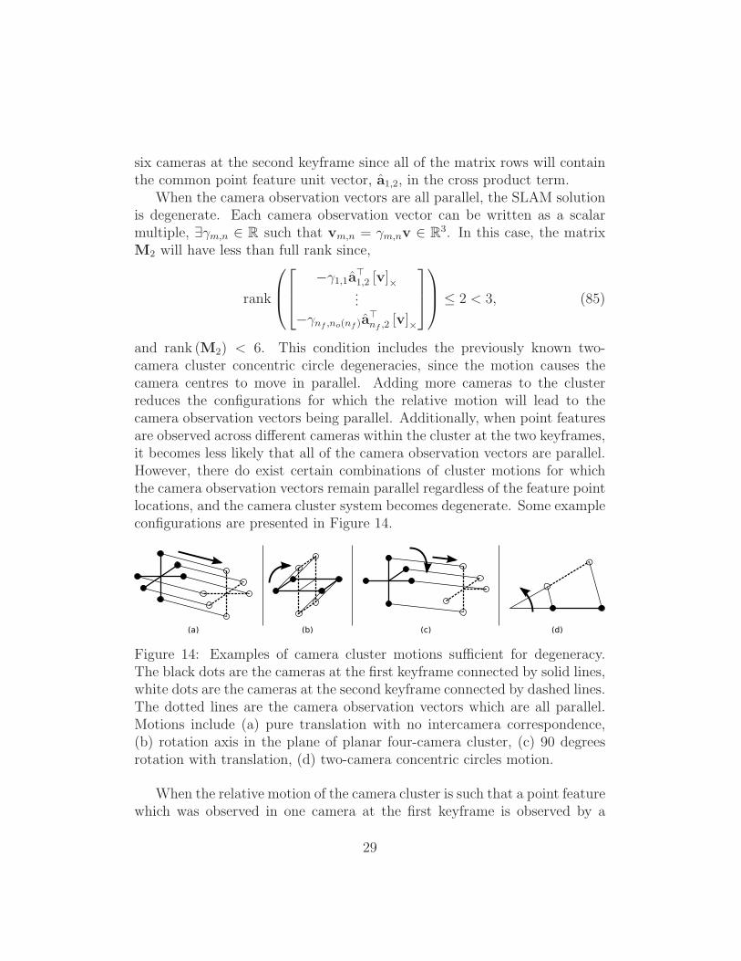
and rank (M2) < 6. This condition includes the previously known two-camera cluster concentric circle degeneracies, since the motion causes thecamera centres to move in parallel. Adding more cameras to the clusterreduces the configurations for which the relative motion will lead to thecamera observation vectors being parallel. Additionally, when point featuresare observed across different cameras within the cluster at the two keyframes,it becomes less likely that all of the camera observation vectors are parallel.However, there do exist certain combinations of cluster motions for whichthe camera observation vectors remain parallel regardless of the feature pointlocations, and the camera cluster system becomes degenerate. Some exampleconfigurations are presented in Figure 14.
(a) (b) (c) (d)
Figure 14: Examples of camera cluster motions sufficient for degeneracy.The black dots are the cameras at the first keyframe connected by solid lines,white dots are the cameras at the second keyframe connected by dashed lines.The dotted lines are the camera observation vectors which are all parallel.Motions include (a) pure translation with no intercamera correspondence,(b) rotation axis in the plane of planar four-camera cluster, (c) 90 degreesrotation with translation, (d) two-camera concentric circles motion.
When the relative motion of the camera cluster is such that a point featurewhich was observed in one camera at the first keyframe is observed by a
29

different camera at the second keyframe, there is a camera observation vectorbetween the positions of the two cameras when they observed the particularpoint feature. This can create a set of camera observation vectors whichare non-parallel even when the relative motion is a pure translation. As aresult, it is possible that the system is non-degenerate and the solution canbe found in this case, depending on the rank of the matrix M2. Observingcommon point features over multiple cameras is an effective way of avoidingthe set of camera observation vectors becoming parallel and reducing the setof sufficient motions for system degeneracy.
4.4. Necessary and Sufficient Conditions for Degeneracy
In the case when the motion does not produce parallel camera observationvectors, it is necessary to evaluate the rank of the matrix M2 before conclud-ing that the system is non-degenerate. The matrix M2 can be regarded asa set of motion constraints on a mechanism where a non-full rank meansthat the framework is not rigid and the configuration can change withoutviolating the constraints. The full analysis of these singular configurationsis beyond the scope of this work, but this section presents a set of exampleconfigurations for some general case systems to numerically demonstrate theeffect of adding additional cameras and point feature observations on thedegenerate configuration set. The experiments presented in this section arenot exhaustive, but serve to suggest why previous practical implementationsof the multicamera cluster SLAM problem converge to an accurate solutionwhen observing many point features, provided the critical motions identifiedin Section 4.3 are avoided.{I-3}
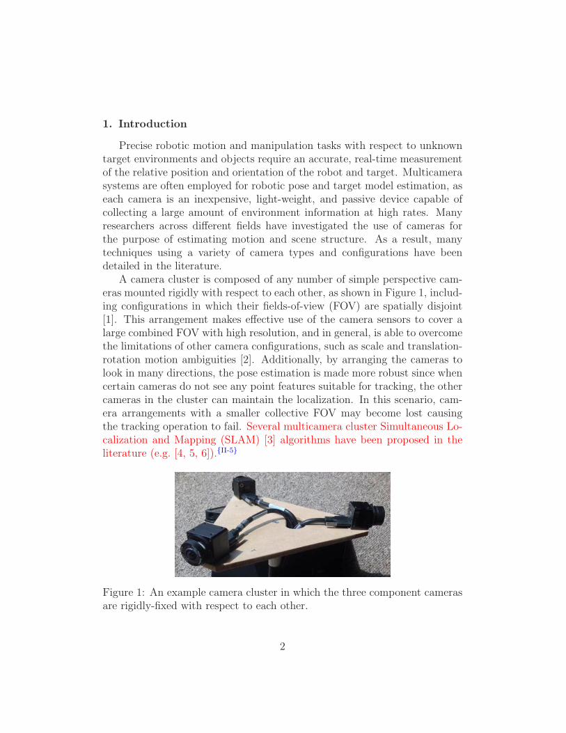
Figures 15a and 15b show typical surface meshes for the relative clustertranslation, tK , leading to M2 losing rank for example two and three-cameracluster systems observing six point features with no overlap in the camera ob-servations and non-zero relative rotation. No measurement noise was addedto these observations.{I-14} The surface is computed numerically as the locusof zero determinant for the matrix M2 using a set of randomly-positionedpoint features. A similar surface is generated for any non-zero rotation RK .
As more point feature observations are added to the system, the numberof degeneracies is reduced. With more than six point feature observations,the size of the matrix M2 becomes mo × 6, where mo > 6 and therefore therank of the matrix cannot be checked by computing the determinant directly.Instead, for the matrix to not be full rank, all of the mo choose 6 submatricesof size 6× 6 formed by the rows of M2 must have a zero determinant. Each
30

−50
5
−5
0
5−5
0
5
tx (m)ty (m)
t z(m
)
(a) Two cameras
−50
5
−5
0
5−5
0
5
tx (m)ty (m)
t z(m
)
(b) Three cameras
Figure 15: Degenerate tK for (a) two and (b) three-camera clusters, observingsix points with no overlap and non-zero rotation.
of the submatrices generates a surface as in Figure 15, and therefore, M2 hasdeficient rank at the tK where all of the surfaces intersect.
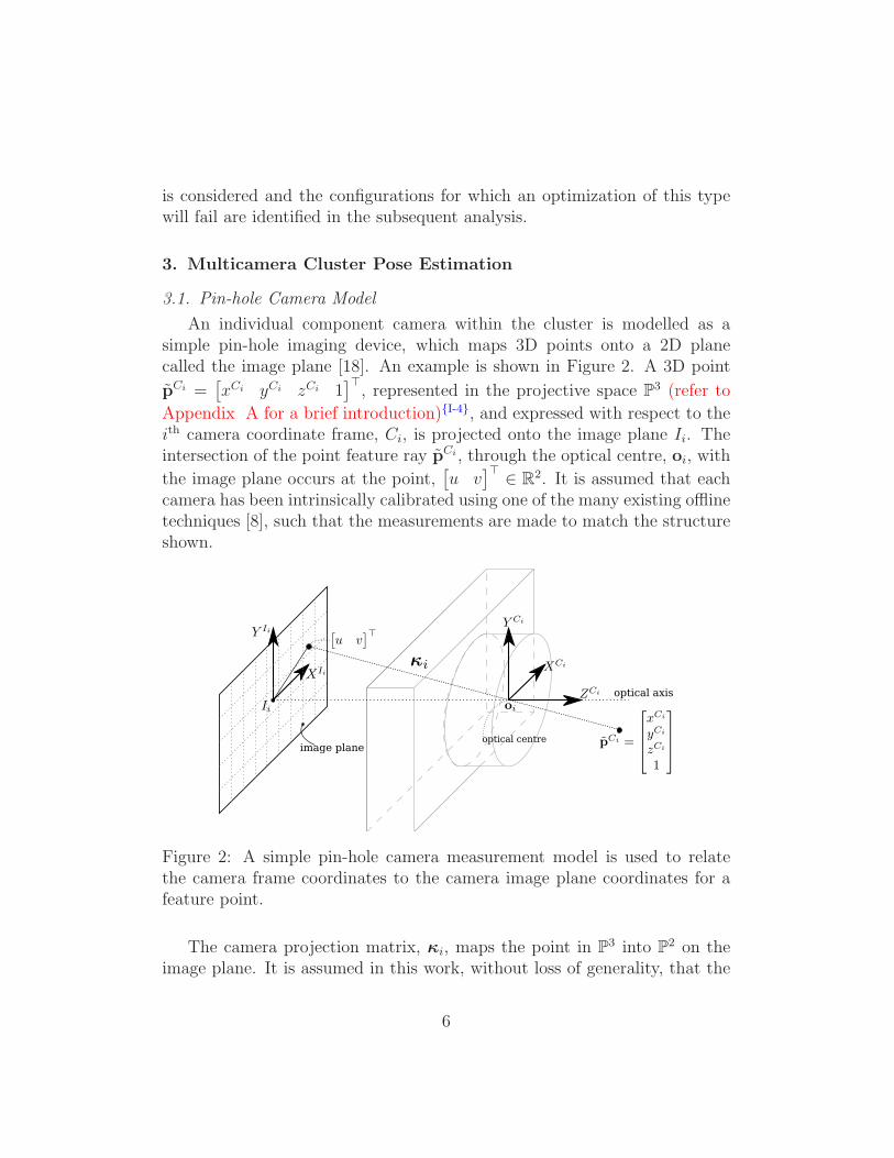
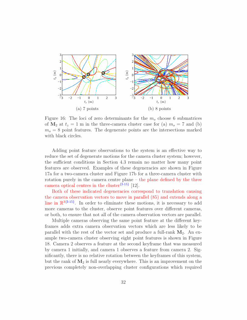
A two-dimensional cross-section at tz = 1 m is shown in Figure 16 for thethree-camera case observing 7 and 8 point features with no overlap and non-zero rotation. The degenerate cluster translations correspond to the pointson the graph where all of the curves intersect and are marked as black circles.These intersections are determined numerically using the computed loci forthe determinants of the submatrices. If all of the loci intersect with eachother within a certain epsilon ball, the location is selected as a degeneracyof M2.
Notice that the number of degenerate motions is reduced from the curvesof each colour for a subset of six feature observations, to a small finite set ofpoints at any given cross-section. While the indicated degenerate positionsare subject to numerical precision considerations, these examples are moreinformative in demonstrating that the system is non-degenerate in almost allconfigurations.
It is observed that the degenerate points in Figure 16a connect as linesin R
3 at different slices of tz. When observing eight points in general posi-tion, Figure 16b shows that there are no translations for which the system isdegenerate. While not exhaustive, numerical analysis of the singular configu-rations of M2 shows that the set of degenerate motions in the cluster systemhas been reduced from the previous surface with mo = 6, to a set of lineswith mo = 7 and the origin for mo = 8.
31
−3 −2 −1 0 1 2 3−3
−2
−1
0
1
2
3
tx (m)
t y(m
)
(a) 7 points
−3 −2 −1 0 1 2 3−3
−2
−1
0
1
2
3
tx (m)
t y(m
)
(b) 8 points
Figure 16: The loci of zero determinants for the mo choose 6 submatricesof M2 at tz = 1 m in the three-camera cluster case for (a) mo = 7 and (b)mo = 8 point features. The degenerate points are the intersections markedwith black circles.
Adding point feature observations to the system is an effective way toreduce the set of degenerate motions for the camera cluster system; however,the sufficient conditions in Section 4.3 remain no matter how many pointfeatures are observed. Examples of these degeneracies are shown in Figure17a for a two-camera cluster and Figure 17b for a three-camera cluster withrotation purely in the camera centre plane – the plane defined by the threecamera optical centres in the cluster{I-15} [12].
Both of these indicated degeneracies correspond to translation causingthe camera observation vectors to move in parallel (85) and extends along aline in R
3{I-15}. In order to eliminate these motions, it is necessary to addmore cameras to the cluster, observe point features over different cameras,or both, to ensure that not all of the camera observation vectors are parallel.
Multiple cameras observing the same point feature at the different key-frames adds extra camera observation vectors which are less likely to beparallel with the rest of the vector set and produce a full-rank M2. An ex-ample two-camera cluster observing eight point features is shown in Figure18. Camera 2 observes a feature at the second keyframe that was measuredby camera 1 initially, and camera 1 observes a feature from camera 2. Sig-nificantly, there is no relative rotation between the keyframes of this system,but the rank of M2 is full nearly everywhere. This is an improvement on theprevious completely non-overlapping cluster configurations which required
32

−3 −2 −1 0 1 2 3−3
−2
−1
0
1
2
3
tx (m)
t y(m
)
(a) Two cameras
−3 −2 −1 0 1 2 3−3
−2
−1
0
1
2
3
tx (m)
t y(m
)
(b) Three cameras
Figure 17: The loci of zero determinants for the 8 choose 6 submatrices ofM2 at tz = 1 m in the (a) two-camera and (b) three-camera cluster case withrotation axis within the camera centre plane observing eight point features
non-zero rotation to have a full-rank M2 (e.g. [7, 11]){I-16}.The example systems in this section demonstrate numerically the effect of
adding cameras and point feature observations to the camera cluster SLAMsolution. For any algorithm, the overall strategy should be to reduce thenumber of degenerate configurations by increasing the number of point fea-tures observed on the target, and then eliminating the remaining sufficientconditions for degeneracy by adding cameras to the cluster, or observingpoint features across cameras, such that it is impossible for all of the cameraobservation vectors to be parallel through the motion. This will ensure awell-constrained solution to the localization and mapping problem.
4.5. Practical Considerations
For this analysis, the deterministic system was used to identify the de-generate cases. In the practical SLAM system, any amount of measurementerror will push the solution off of the degenerate configuration surface (64)identified in this analysis. Additionally, it is unlikely that M2 would losefull rank due to numerical considerations, but would become ill-conditioned.Monitoring the condition number of the matrix would provide an informativemeasure of how close the system is to degeneracy.
In particular, the system scale is very insensitive to the image measure-ments as the configurations approach degeneracy. In the presence of noiseor errors associated with common feature extraction methods, the solution
33

−3 −2 −1 0 1 2 3−3
−2
−1
0
1
2
3
tx (m)
t y(m
)
Figure 18: The loci of zero determinants for the 8 choose 6 submatrices ofM2 at tz = 1 m in the two-camera cluster system with zero rotation betweenkeyframes, but two common features across cameras.
will converge to one particular, likely incorrect scale. This may be partiallyaccounted for in the optimization using error modeling techniques such asZeisl et al. [27].
In the same way as for traditional stereo systems, the ratio of the baselineto the depth of the point features plays a large role in the sensitivity of thesystem solution to the image measurements. For the camera cluster case,there are two ratios to consider. First, when the baselines within the cameracluster are small compared to the feature depth, and second, when the clustertranslation is small compared to the feature depth. Both of these cases willresult in a system that is sensitive to measurement noise, particularly whenthere is no overlap between the different camera FOV. As the two ratiosbecome larger, more measurement noise may be tolerated.{II-2}
In the extreme case where the point features are significantly far awayfrom the camera and approximate points at infinity, the previous two ra-tios approach zero and there is no information with which to triangulatethe point feature depth or the length of the cluster translation. While thisanalysis makes the assumption that all point features have finite depth, largedistances combined with the presence of measurement noise, make the prac-tical solution vulnerable to this case. The result would be that the matrixM3 loses full rank or becomes ill-conditioned. However, even though thereis insufficient information in the measurements to estimate the depths ofthe point features and cluster translation, observing extra points at infinitywould help constrain the orientation and bearing estimates in the system
34

[28]. If all of the point features were infinitely far from the camera, the prob-lem would need to be reformulated to that of a visual compass [29] to avoidover-parametrization.{II-3}
While this analysis identified the degenerate configurations of the system,these represent the extreme end of the sensitivity spectrum. In future work,further sensitivity analysis would examine the intermediate behaviour of thesystem solution with respect to the point feature image measurements.{II-2}
5. Conclusions
This work presented a detailed analysis of the degenerate configurationsof the calibrated non-overlapping FOV multicamera cluster SLAM problemfor an optimization based on minimizing a least-squares cost function withrespect to the image-plane reprojection error. The system is reduced to asimple matrix rank test on a matrix consisting of rows of Plucker coordinatesfor lines in R
3. Sufficient configurations for solution degeneracy caused by therelative motion were identified for nc-camera clusters observing any numberof point features over two keyframes. This leads to the novel general conclu-sion that if all of the camera observation vectors, formed as the displacementbetween the pairs of cameras observing a particular point feature, are parallelin a common coordinate frame, then the system is degenerate. It is furthershown for several example systems that with the addition of more camerasto the cluster, more point feature observations, and observations of the pointfeatures across different cameras, the set of degenerate configurations is sig-nificantly reduced as it becomes impossible for all of the identified vectors tobe parallel and the redundant observations prevent all of the determinantsof the submatrices from going to zero concurrently.
Future work will focus on fully characterizing the necessary and sufficientconditions for the system to become degenerate, including the degeneraciesrelated to the geometry of the point feature constellation from the standpointof geometric algebra techniques [30].
Additionally, the results from this work will be used to generate metricsfor deciding when and where to add keyframes in a real-time SLAM systemto accurately construct and constrain the generated target model and avoidthe degeneracies within the state space caused by measurements from thistype of sensor.
Finally, most SLAM systems detect and reject non-rigid target structureby monitoring measurement residuals when back-projecting the points back
35

into the camera images. Further investigation is warranted into the possibil-ity of any of the metrics arising from this analysis providing an indicator todetect non-rigid target structure.{II-4}
Acknowledgements
This work was partially funded by the National Sciences and EngineeringResearch Council of Canada (NSERC) under Grant No. CRDPJ 397768-10 and supported through the NSERC Canadian Field Robotics Network(NCFRN){AC}. Partial funding also comes from the NSERC through theAlexander Graham Bell Canada Graduate Scholarship - Doctoral (CGS-D)award.
Appendix A. Projective Geometry
The projective space, Pr, consists of the real vector space Rr, with the
addition of points at infinity [8]. Only a very brief description of the pro-jective space is presented here and the reader is referred to [8] for a morethorough introduction.
A point in the projective space is represented by the r + 1 homogeneouscoordinates,
x =[x1 x2 . . . xr+1
]⊤∈ P
r. (A.1)
The points at infinity in Rr are represented by those with coordinate xr+1 =
0. For finite points in Rr – when xr+1 6= 0 – the coordinates of the corre-
sponding point x ∈ Rr are determined by,
x =[x1 x2 . . . xr
]⊤(A.2)
=
[x1
xr+1
x2
xr+1
. . .xr
xr+1
]⊤
. (A.3)
Note that there is no way of mapping a point at infinity back to Rr since it
would require division by zero.Each point along a ray in the projective space maps to the same point
in the real vector space. As a result, the points x and λx, for λ ∈ R, mapto the same point x ∈ R
r. Not surprisingly, there is an extra degree of
36
freedom in the projective vectors using r + 1 coordinates to represent a r-dimensional space. Finally, it is possible to represent any point x ∈ R
r in thecorresponding projective space P
r simply by augmenting the coordinates,
x =[x⊤ 1
]⊤. (A.4)
The projective spaces allow for projective and coordinate transformationsto be represented as linear matrix operations.
It will sometimes be necessary to move between the respective real andprojective space representation of points, and the following promotion anddemotion operators are defined. The projective promotion operator ρ : Rr →Pr maps a point x in the real vector space to its representation in the pro-
jective space,
ρ (x) =[x⊤ 1
]⊤. (A.5)
The projective demotion operator πr : Pr → R
r maps a point x in theprojective space back to the corresponding point x the real vector space,
x = πr (x) (A.6)
=
undefined if xr+1 = 0[
x1
xr+1
x2
xr+1
. . .xr
xr+1
]⊤
if xr+1 6= 0.(A.7)
Note that the result of this operator is undefined for points at infinity.In this work, unless it is ambiguous from the context, the promotion and
demotion operators will be implied by the vector notation. The homogeneouscoordinates for a given vector x ∈ R
r will simply be written as x ∈ Pr, but
implicitly, x ≡ ρ (x), and likewise, x ≡ πr (x) assuming xr+1 6= 0.{I-4,I-5}
References
[1] P. Baker, C. Fermuller, Y. Aloimonos, R. Pless, A spherical eye frommultiple cameras (makes better models of the world), in: Proceedingsof the IEEE Conference on Computer Vision and Pattern Recognition(CVPR), 2001, pp. 576–583.
[2] R. Pless, Using many cameras as one, in: Proceedings of the IEEE Con-ference on Computer Vision and Pattern Recognition (CVPR), Vol. 2,2003, pp. II–587–593.
37

[3] S. Thrun, W. Burgard, D. Fox, Probabilistic robotics, The MIT Press,2005.
[4] M. J. Tribou, A. Harmat, D. W. L. Wang, I. Sharf, S. L. Waslander,Multi-camera parallel tracking and mapping with non-overlapping fieldsof view, The International Journal of Robotics Research.
[5] T. Kazik, L. Kneip, J. Nikolic, M. Pollefeys, R. Siegwart, Real-time 6Dstereo visual odometry with non-overlapping fields of view, in: Proceed-ings of the IEEE Conference on Computer Vision and Pattern Recogni-tion (CVPR), 2012, pp. 1529–1536.
[6] M. Kaess, F. Dellaert, Probabilistic structure matching for visual SLAMwith a multi-camera rig, Computer Vision and Image Understanding114 (2) (2010) 286–296.
[7] B. Clipp, J. H. Kim, J. M. Frahm, M. Pollefeys, R. Hartley, Robust6DOF motion estimation for non-overlapping, multi-camera systems,in: Proceedings of the IEEE Workshop on Applications of ComputerVision (WACV), 2008, pp. 1–8.
[8] R. Hartley, A. Zisserman, Multiple view geometry in computer vision,Cambridge University Press, 2003.
[9] A. J. Davison, I. D. Reid, N. D. Molton, O. Stasse, MonoSLAM: Real-time single camera SLAM, IEEE Transactions on Pattern Analysis andMachine Intelligence 29 (6) (2007) 1052–1067.
[10] R. Hermann, A. Krener, Nonlinear controllability and observability,IEEE Transactions on Automatic Control 22 (5) (1977) 728–740.
[11] J. H. Kim, M. J. Chung, B. T. Choi, Recursive estimation of motionand a scene model with a two-camera system of divergent view, PatternRecognition 43 (6) (2010) 2265–2280.
[12] M. J. Tribou, S. L. Waslander, D. W. L. Wang, Scale recovery in mul-ticamera cluster SLAM with non-overlapping fields of view, ComputerVision and Image Understanding 126 (2014) 53–66.
[13] H. Stewenius, D. Nister, M. Oskarsson, K. Astrom, Solutions to minimalgeneralized relative pose problems, in: Proceedings of the Workshop onOmnidirectional Vision, 2005.
38

[14] P. Sturm, Multi-view geometry for general camera models, in: Proceed-ings of the IEEE Conference on Computer Vision and Pattern Recogni-tion (CVPR), Vol. 1, 2005, pp. 206–212.
[15] E. Mouragnon, M. Lhuillier, M. Dhome, F. Dekeyser, P. Sayd, Genericand real-time structure from motion using local bundle adjustment, Im-age and Vision Computing 27 (8) (2009) 1178–1193.
[16] J. S. Kim, T. Kanade, Degeneracy of the linear seventeen-point algo-rithm for generalized essential matrix, Journal of Mathematical Imagingand Vision 37 (1) (2010) 40–48.
[17] H. Li, R. Hartley, J. H. Kim, A linear approach to motion estimationusing generalized camera models, in: Proceedings of the IEEE Confer-ence on Computer Vision and Pattern Recognition (CVPR), 2008, pp.1–8.
[18] Y. Lu, J. Z. Zhang, Q. M. J. Wu, Z. N. Li, A survey of motion-parallax-based 3-D reconstruction algorithms, IEEE Transactions on Systems,Man, and Cybernetics 34 (4) (2004) 532–548.
[19] R. M. Murray, Z. Li, S. S. Sastry, A mathematical introduction to roboticmanipulation, CRC Press, 1994.
[20] E. Rosten, T. Drummond, Fusing points and lines for high performancetracking., in: Proceedings of the IEEE International Conference onComputer Vision (ICCV), Vol. 2, 2005, pp. 1508–1511.
[21] E. Rosten, T. Drummond, Machine learning for high-speed corner detec-tion, in: Proceedings of the European Conference on Computer Vision(ECCV), Vol. 1, 2006, pp. 430–443.
[22] D. G. Lowe, Object recognition from local scale-invariant features, Pro-ceedings of the IEEE International Conference on Computer Vision(ICCV) 2 (1999) 1150–1157.
[23] H. Bay, A. Ess, T. Tuytelaars, L. Van Gool, Speeded-up robust features(SURF), Computer Vision and Image Understanding 110 (3) (2008) 346–359.
39
[24] G. Klein, D. Murray, Parallel tracking and mapping for small ARworkspaces, in: Proceedings of the IEEE and ACM International Sym-posium on Mixed and Augmented Reality (ISMAR), 2007, pp. 225–234.
[25] J. Civera, A. J. Davison, J. M. M. Montiel, Inverse depth parametriza-tion for monocular SLAM, IEEE Transactions on Robotics 24 (5) (2008)932–945.
[26] N. L. White, Grassmann-Cayley algebra and robotics, Journal of Intel-ligent and Robotic Systems 11 (1-2) (1994) 91–107.
[27] B. Zeisl, P. F. Georgel, F. Schweiger, E. G. Steinbach, N. Navab, Es-timation of location uncertainty for scale invariant features points, in:Proceedings of the British Machine Vision Conference (BMVC), 2009,pp. 1–12.
[28] J. Schneider, F. Schindler, T. Labe, W. Forstner, Bundle adjustment formulti-camera systems with points at infinity, in: ISPRS Annals of Pho-togrammetry, Remote Sensing and Spatial Information Sciences, Vol.I-3, 2012, pp. 75–80.
[29] J. M. M. Montiel, A. J. Davison, A visual compass based on SLAM,in: Proceedings of the IEEE International Conference on Robotics andAutomation (ICRA), 2006, pp. 1917–1922.
[30] L. Dorst, D. Fontijne, S. Mann, Geometric Algebra for Computer Sci-ence: An Object-Oriented Approach to Geometry, Morgan Kaufmann,2010.
Vitae
Michael J. Tribou
Michael J. Tribou received the B.A.Sc. degree from Queen’s University,Kingston, ON, Canada, in 2007, and the M.A.Sc. and Ph.D. degrees fromthe University of Waterloo, Waterloo, ON, Canada, in 2009 and 2014, re-spectively.
In 2014, he joined Aeryon Labs Inc. and is currently working as a ControlSystems Developer in Waterloo, ON, Canada. His research interests includevision-based pose estimation and control of autonomous vehicles.
40

Steven L. Waslander
Steven L. Waslander received his Ph.D. from Stanford University in 2007,his M.S. from Stanford University in 2002, both in Aeronautics and Astro-nautics, and his B.Sc.E. in 1998 from Queen’s University.
In 2008, he joined the Department of Mechanical and Mechatronics Engi-neering at the University of Waterloo in Waterloo, ON, Canada, where he isnow an Associate Professor. He is the Director of the Waterloo AutonomousVehicles Laboratory (WAVELab, http://wavelab.uwaterloo.ca). His researchinterests are in the areas of autonomous aerial and ground vehicles, simul-taneous localization and mapping, nonlinear estimation and control, andmulti-vehicle systems.
David W. L. Wang
David W. L. Wang received the B.E. degree from the University of Saskat-chewan, Saskatoon, SK, Canada, in 1984, and the M.A.Sc. and Ph.D. degreesfrom the University of Waterloo, Waterloo, ON, Canada, in 1986 and 1989,respectively.
In 1990, he joined the Department of Electrical and Computer Engineer-ing, University of Waterloo, and was promoted to Full Professor in 1999. Hewas Associate Chair for Graduate Studies from 1998 to 2000. His researchinterests include nonlinear control, flexible manipulators/structures, shapememory alloy actuators, and haptic interfaces.
41