Embed Size (px)
Citation preview


2
deforming or developing play in excess of 0.05 inch. Flat metal anchors are not acceptable.
2. Screw-Attached, Masonry-Veneer Anchors: Units consisting of a wire tie
and a metal anchor section. a. Anchor Section: Zinc-alloy barrel section with flanged head with eye
and corrosion-resistant, self-drilling screw. Eye designed to receive wire tie and to serve as head for drilling fastener into framing. Barrel length to suit sheathing thickness, allowing screw to seat directly against framing with flanged head covering hole in sheathing.
b. Wire Ties: Triangular-, rectangular-, or T-shaped wire ties fabricated from 0.188inch-diameter, hot-dip galvanized steel wire.”
C. SECTION 042000, 1.05 QUALITY ASSURANCE , DELETE Paragraph C in its entirety. ADD in its place, Paragraph C. as follows:
“C. Masonry Testing Service: The Contractor shall engage a testing laboratory to test mortar and grout compositions, properties, and strengths.”
D. SECTION 042000, 3.12 QUALITY CONTROL, DELETE Paragraph A in its entirety. ADD in its place, Paragraph A. as follows:
“A. The Contractor shall employ and pay all costs for a testing laboratory to perform quality control testing during construction, including a certified technician to obtain samples at the job site.”
E. ADD to the table of contents under Division 7 a. Section 077200 Roof Accessories
F. ADD to the table of contents under Division 10
b. Section 101000 Marker Boards and Projection screens
G. Section 051200, Paragraph 1.6B, DELETE in its’ entirety; ADD in its place the following:
“B. Installer Qualifications: Engage an experienced Installer who has completed structural steel work similar in material, design, and extent to that indicated for this Project and with a record of successful in-service performance.”
H. ADD the following section (attached)
c. Section 077200 Roof Accessories
I. ADD the following section (attached) d. Section 101000 Marker Boards and Projection screens
J. Section 102813 Toilet and Bath Accessories, Paragraph 1.03 C, DELETE all “NIC” reference. K. Section 102813 Toilet and Bath Accessories, Paragraph 2.01 A-M, DELETE all “NIC” reference.
3
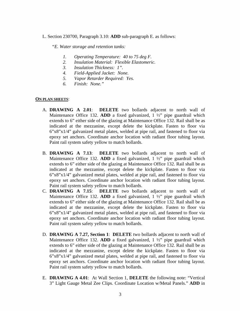
L. Section 230700, Paragraph 3.10: ADD sub-paragraph E. as follows:
“E. Water storage and retention tanks:
1. Operating Temperature: 40 to 75 deg F. 2. Insulation Material: Flexible Elastomeric. 3. Insulation Thickness: 1”. 4. Field-Applied Jacket: None. 5. Vapor Retarder Required: Yes. 6. Finish: None.”
ON PLAN SHEETS:
A. DRAWING A 2.01: DELETE two bollards adjacent to north wall of Maintenance Office 132. ADD a fixed galvanized, 1 ½” pipe guardrail which extends to 6” either side of the glazing at Maintenance Office 132. Rail shall be as indicated at the mezzanine, except delete the kickplate. Fasten to floor via 6”x8”x1/4” galvanized metal plates, welded at pipe rail, and fastened to floor via epoxy set anchors. Coordinate anchor location with radiant floor tubing layout. Paint rail system safety yellow to match bollards.
B. DRAWING A 7.13: DELETE two bollards adjacent to north wall of Maintenance Office 132. ADD a fixed galvanized, 1 ½” pipe guardrail which extends to 6” either side of the glazing at Maintenance Office 132. Rail shall be as indicated at the mezzanine, except delete the kickplate. Fasten to floor via 6”x8”x1/4” galvanized metal plates, welded at pipe rail, and fastened to floor via epoxy set anchors. Coordinate anchor location with radiant floor tubing layout. Paint rail system safety yellow to match bollards.
C. DRAWING A 7.15: DELETE two bollards adjacent to north wall of Maintenance Office 132. ADD a fixed galvanized, 1 ½” pipe guardrail which extends to 6” either side of the glazing at Maintenance Office 132. Rail shall be as indicated at the mezzanine, except delete the kickplate. Fasten to floor via 6”x8”x1/4” galvanized metal plates, welded at pipe rail, and fastened to floor via epoxy set anchors. Coordinate anchor location with radiant floor tubing layout. Paint rail system safety yellow to match bollards.
D. DRAWING A 7.27, Section 1: DELETE two bollards adjacent to north wall of Maintenance Office 132. ADD a fixed galvanized, 1 ½” pipe guardrail which extends to 6” either side of the glazing at Maintenance Office 132. Rail shall be as indicated at the mezzanine, except delete the kickplate. Fasten to floor via 6”x8”x1/4” galvanized metal plates, welded at pipe rail, and fastened to floor via epoxy set anchors. Coordinate anchor location with radiant floor tubing layout. Paint rail system safety yellow to match bollards.
E. DRAWING A 4.01: At Wall Section 1, DELETE the following note: “Vertical 3” Light Gauge Metal Zee Clips. Coordinate Location w/Metal Panels.” ADD in

4
its place the following note: “Horizontal 3” Light Gauge Metal Zee Clips. Coordinate Location w/Metal Panels.”
F. DRAWING A 4.04: At Wall Section 10, DELETE the following note: “Vertical 3” Light Gauge Metal Zee Clips.” ADD in its place the following note: “Horizontal 3” Light Gauge Metal Zee Clips.”
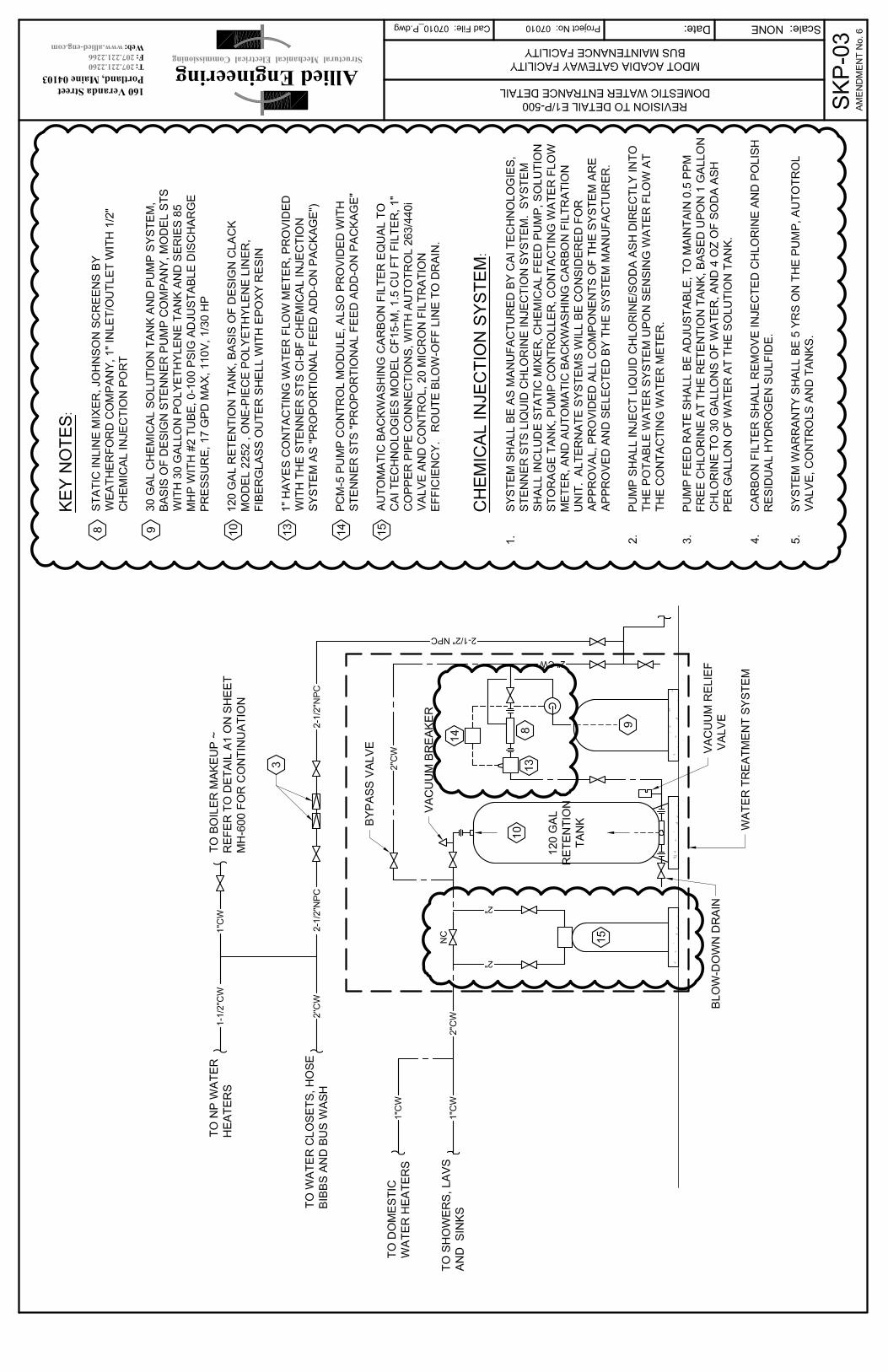
G. DRAWING P-500: At Key Notes, DELETE key notes #8, #9, and #10 in their entirety. ADD in their place, Key notes #8, #9, and #10 as contained on SKP-03, attached.
H. DRAWING P-500: At Key Notes, ADD Key notes #13, #14, and #15 as contained on SKP-03, attached.
I. DRAWING P-500: ADD “Chemical Injection System” Notes #1, 2, 3, 4, and 5 as contained on SKP-03, attached.
J. DRAWING P-500: REVISE Domestic Water Entrance Detail E1 as outlined on SKP-03, attached.
K. DRAWING E-000: At Detail G1, Local Sound System and Speakers, DELETE the note referencing Division 17 in its entirety.
L. DRAWING ES-100: At Detail C9, Legend, DELETE telcom/CATV handhole description in its entirety. ADD in its place the following:
Telcom/CATV handhole, minimum 18”x36”x24”, size per larger of NEC requirements for number of conduits installed or utility company standards. At each handhole, provide (2) 4” conduit stubs for telephone utility pedestal in addition to indicated conduits. Coordinate pedestal locations with utility.
M. DRAWING ES-100: At Detail C9, Legend, DELETE 4’ x 6’ pull box description in its entirety. ADD in its place the following:
Pullbox per utility standards. Coordinate exact locations with utility
N. DRAWING ES-500: DELETE Transformer pad detail A4 in its entirety. ADD in its place the transformer vault detail indicated on attached sketch SKE-05.
O. DRAWING EP-400: ADD a pedestal mounted meter socket between Panel ‘S’
and the Parking Lot XFMR. Route the indicated feeder from the XFMR to Panel ‘S’ via this meter socket.
P. NOTE: Disregard the following direction provided in Amendment # 2 “DRAWING SB-100 - DELETE reference to Section A3-SB500 at exterior radiant slab at egress bus wash. ADD in its’ place A7-SB500.”
Q. At the end of the Plans – Add the following details referenced in the prebid meeting questions of October 15, 2009, answers to PB-4: Ken Shea;

5
CSK-1, SKS-01 and SKS-02
PREVIOUSLY NOTED ITEMS: RFI #26 Question#1: We assume that the disadvantaged business enterprise goal for participation of 1.9% listed on page 21 of the USADOT Federal Transit Administration Contract Requirements (issued with addendum/amendment #1) supersedes the 5.8% goal contained in the notice attached to the Federal Project Requirements that was provided with the bid documents. Please advise if we are wrong.
Response: It is correct that the 1.9% supersedes the 5.8%. RFI #27 Question#1: Please clarify; In spec section 084113-2 1.03 D and spec section 085113-2 1.04 C it calls for Windborne Debris Resistance. If this is required, the windows, glass, store front and curtain wall systems that are drawn and specified will not meet this impact resistance. Please advise if this is required.
Response: No. The Acadia Gateway Center is not located within a wind borne debris region (i.e. in an area within 1-mile of the coastal mean high water line or where the basic wind speed is 120 mph or more) as the basic wind speed is 90 mph (MMBC §1609.2 * MMBC F-1609). As such openings (e.g. windows & doors) are not required to resist wind borne debris (re. ASTM E1996_Large Missile Test).
RFI #29: Question #16: Bid Form Line No. 0660 - is this meant for just the general contractor and all subs should bid by their specific line item number (i.e . their mobilization/demobilization and general conditions will be included in their specific Line No.)?
Response: Yes. RFI #33 (MDOT #34): Question #1: We are unable to locate specifications for the following items: - Aluminum Fence - Flagpole - Concrete Pavers

6
Please provide all required specifications.
Response: - Aluminum fence-Refer to Amendment #4. - Flagpole specification was provided in Amendment #4. - Concrete Pavers shall be Genest Hollandstone Paving Stones as supplied
by Genest Concrete, Sanford, Maine or approved equal.
RFI #34 (MDOT #35): Question #1: We are unable to locate specifications for the following items: - Plantings - Floor Expansion Joint Covers - Light Tubes Please provide all required specifications.
Response: -For plantings, see Response to RFI #65. -Covers shall be In-Pro Jointmaster 806 Series, mill finish aluminum, or equal as approved by Architect. -Light Tubes – Specification 086250 Tubular skylights was provided in amendment #4.
RFI #63 Question #1: Please clarify orientation of 3” light gauge metal zee clips in typical wall sections 1 on A 401 and 10 on A 404. They are labeled vertical but drawn horizontal. Response: Zee clips are intended to always be horizontal. Refer to amendment items herein for clarification to the drawings. Question #2: At 2” horizontal ribbed metal panels, should they be vertical? Response: No, the horizontal ribbed metal wall panels are intended to be 7/8” dimension, attached to vertical ¾” subgirts, which are, in turn, attached to horizontal zee clips. Question #3: At 2” vertical metal panels, should they be horizontal? Response: Yes, zee clips shall be horizontal
7
Question #4: At 7/8” horizontal ribbed metal panels with vertical ¾” subgirts, should they be horizontal? Response: Yes, zee clips shall be horizontal Question #5: At 1 ½” vertical metal panels, should they be horizontal? Response: Yes, zee clips shall be horizontal PREBID MEETING QUESTIONS OCTOBER 15, 2009 PB-1: James Nason of Perry and Morrill
b. There is no specification on the FRP panel to use at the skylights?
Response: The specification is SECTION 08 45 23 - INSULATED TRANSLUCENT FIBERGLASS SANDWICH PANEL SKYLIGHT SYSTEM. This is an option to the SECTION 08 63 00 – METAL FRAMED SKYLIGHTS.
e. There is no specification for mailboxes, roll-up screens or white boards.
Please provide.
Response: Mailboxes are shown on Dwg. A7.23; also refer to 06400 - Architectural Woodwork specification. Specifications for roll-up screen and white boards are attached to this Amendment.
PB-2: Bill Boulier, Nickerson and O’Day
a. The revised buy America requirements obviously added manufactured products which are typical, but there was a statement that said unless a waiver has been granted by FTA, has there been any other provisions to the Buy America requirement to allow, for instance, Canadian steel?
Response: No. There have been no other provisions to the Buy America requirement.
d. The bonding requirements have been changed dramatically with
Amendment #1. Have those been addressed to be revised?
Response: They were changed in Amendment #2 PB-3: Chuck Snyder, Ed Hodson Masonry

8
a. With the 4” split-face CMU, it calls for vertical reinforcement in the architectural drawing. The cells on a 4” split-face block, normally they do not have cells, usually, they are solid block. When they do come with cells, they come in 3 cell units. When you lay these in a running bond pattern, the cell openings between the blocks is only 1 ½ x ¾” and we have to put #5 rebar down through?
Response: The 4” split-face shall have cores and shall be reinforced with #3 rebar. Note #22 has been added by this amendment to A4/S-000 which describes reinforcement requirements for the block. CHANGE RESPONSE: The exterior 4 ” split face block shall be solid, with no vertical reinforcement required. Provided reinforcement schedule for 4” CMU shall apply to interior free standing partitions, only.
c. UL rating for the 4 inch split face #723, we can’t find a book or section in the book that defines this UL listing. Can you provide help on locating this UL listing.
Response: Please delete the requirement for a UL rating on the split face block
d. In division 042000, Summary Section 1.02/5A, solid ground faced
masonry. Is this speaking about the SMU cap at the top of the 4 inch split face??
Response: YES
i. The CMU sill at the top of the split face, can we use mitered corners at outside corners?
Response: YES
PB-4: Ken Shea
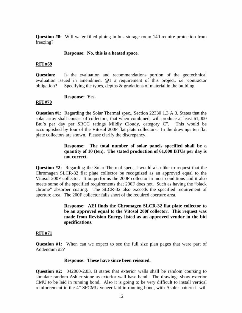
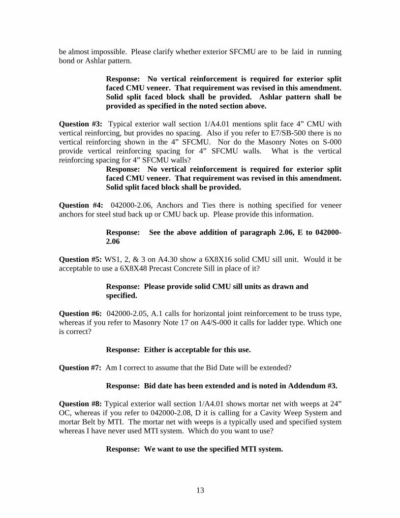
c. Is there any insulation under the exterior slab that's got heat in it? Response: All concrete aprons at the bay ingress/egress locations shall receive 4” rigid insulation beneath the slabs. This is true also for the radiant slab at the egress of the bus wash bay. All sidewalks alongside the building shall receive 4” rigid as well. See attached CSK-1, SKS-01 and SKS-02.
THE FOLLOWING QUESTIONS HAVE BEEN RECEIVED: RFI #64
9
Question #1: If Division 26 includes supply/install conduits and BHE pullboxes and transformer bases, what is potentially covered by the $250,000 allowance for Bangor Hydro?
Response: The allowance covers any Bangor Hydro Electric utility construction charges for items including, but not limited to utility pole placements and/or upgrades, primary underground cable and installation, and padmount transformers and installation.
Question #2: Electrical (Division 26) is lump sum price. Do we have to break, i.e. site work electrical vs. building electrical?
Response: The work of all Division 26 sections shall be included in the lump sum price.
Question #3: Is a temporary pole line along existing entrance driveway a permitted method of supplying temporary power to the building site? I have walked the area and believe pole-setting could be accomplished mostly by truck along the driveway. Would any further DEP or Corps or Engineers permits be required for this?
Response: This action would be allowed along the Old Turnpike Road, on the south side of centerline, as long the installation of the temporary poles would not further impact wetlands. If this cannot be accomplished, please provide further reason/justification of no other alternative approaches to temporary power installation and the Department may consider a permit amendment process.
RFI #65 Question #1: The plant list on plan number C-54 is different from the plant listings under Special Provisions Landscape p.75-76 and the Schedule of Items 621.01 thru 621.711.
Response: The 621 Special Provision Plant Species Specification and Quantities List takes precedence over the plan per agency preliminary review during plan development, and has been corrected further to match the Schedule of Items.
Question #2: Item #621.546 lists a quantity of 76 but this item relates to the rugosa roses which are listed on the plan at a quantity of 70.
Response: Item 621.546 quantity should stand at 76.
Question #3: The plan lists 36 – cornus amomum, 143 - cornus sericea, and 48 – cornus fleviramea lutea none of which are accounted for in the schedule of Items. Which plant count is correct? Please advise.
Response: The Special Provision 621 is the Plant List for the Project.

10
The Cornus amomum, Cornus sericea, and Cornus flaviramea lutea have been deleted.
Question #4: Should we assume that the specification for the planting are the same as the State of Maine Department of Transportation Standard Specifications, Section 621 – landscaping?
Response: Per special Provision 621 “The contractor shall follow MDOT Standard Specifications Rev. December, 2002 for the landscape materials and installation procedures (Sec 621).
RFI #66 Question: Joel, as it pertains to addendum 2, RFI 19, the drawing A8.01 issued, dated 05/01/09, does not show any schedule changes to the items mentio9ned within the addendum, specifically for the bathroom wall tile.
Response: Room finish schedule sheet A8.01 was reissued in amendment #4
RFI #67 Question #1: Refrigerated Compressed-Air Dryers. (There is no section or specification for a refrigerated air dryer) If you want a refrigerated air dryer, I would spec. the following: Quincy Model QPNC-50, rated for 50 CFM at 38F pressure dew point, non-cycling ½ hp, 115/1/60 voltage, “ inlet/outlet.
Response: An air dryer shall not be required as part of this compressed air system.
Question #2: Instrumentation. The following request are not available mounted in the control panel.
Discharge-Air Pressure Gage Air-Filter Maintenance Indicator Discharge-Air and Coolant Temperature Gages
Response: Discharge –Air Pressure Gauge shall be installed at the tank discharge and inline per Detail A1 on sheet PL-103. Air-Filter Maintenance Indicator and a Discharge-Air and Coolant Temperature Gages shall not be required as part of this compressed air system.
Question #3: Interior Finish: Galvanized coating (Quincy will only supply an exterior and interior tank with galvanized coating.)
Response: ASME receiver tank shall be factory painted standard color with non-coated steel interior.
11
Question #4: 2.2 D.9.d. Pressure Rating – Tank pressure rating will be 200 psig not 250 psig.
Response: 200 psig tank pressure rating shall be acceptable for this compressed air system.
RFI #68 Question #1: In regard to the Fire Protection Tank, who owns the excavation and backfilling of the tank?
Response: Excavation is specified under Division 31. Question #2: Who is responsible for the underground sprinkler main connecting the Fire Pump and the sprinkler riser inside the main building?
Response: Site water utility distribution piping is specified under Division 33.
Question #3: Who is responsible for the underground tank fill water line connecting the FP tank and the domestic supply in the main building?
Response: Site water utility distribution piping is specified under Division 33.
Question #4: Is a backflow preventer on the FP tank fill line and jocket feed line, in lieu of a backflow preventer at the sprinkler entrance in the main building acceptable?
Response: Provide backflow prevention both at the tank feed line and the sprinkler entrance, as detailed on A6/FP-500 and E1/P-500.
Question #5: Who is responsible for the main & generator A/C wiring going to the Fire Pump and Fire Pump house?
Response: Wiring to the pump house is included in the work of Division 26. The fire pump house is factory wired for a single point of connection for normal and emergency power supplies.
Question #6: Who is responsible for the Fire alarm wiring between the Fire Pump house and the main FA panel?
Response: This work is included in Division 26. Question #7: Will water filled piping within the cavity space above the wash bay room 139 ceiling require protection from freezing?
Response: No, the building insulation for this space is at the roof deck. Ceiling cavity is a warm space.
12
Question #8: Will water filled piping in bus storage room 140 require protection from freezing?
Response: No, this is a heated space. RFI #69 Question: Is the evaluation and recommendations portion of the geotechnical evaluation issued in amendment @1 a requirement of this project, i.e. contractor obligation? Specifying the types, depths & gradations of material in the building.
Response: Yes. RFI #70 Question #1: Regarding the Solar Thermal spec., Section 22330 1.3 A 3. States that the solar array shall consist of collectors, that when combined, will produce at least 61,000 Btu’s per day per SRCC ratings Mildly Cloudy, category C”. This would be accomplished by four of the Vitosol 200F flat plate collectors. In the drawings ten flat plate collectors are shown. Please clarify the discrepancy.
Response: The total number of solar panels specified shall be a quantity of 10 (ten). The stated production of 61,000 BTUs per day is not correct.
Question #2: Regarding the Solar Thermal spec., I would also like to request that the Chromagen SLCR-32 flat plate collector be recognized as an approved equal to the Vitosol 200F collector. It outperforms the 200F collector in most conditions and it also meets some of the specified requirements that 200F does not. Such as having the “black chrome” absorber coating. The SLCR-32 also exceeds the specified requirement of aperture area. The 200F collector falls short of the required aperture area.
Response: AEI finds the Chromagen SLCR-32 flat plate collector to be an approved equal to the Vitosol 200f collector. This request was made from Revision Energy listed as an approved vendor in the bid specifications.
RFI #71 Question #1: When can we expect to see the full size plan pages that were part of Addendum #2?
Response: These have since been reissued.
Question #2: 042000-2.03, B states that exterior walls shall be random coursing to simulate random Ashler stone as exterior wall base band. The drawings show exterior CMU to be laid in running bond. Also it is going to be very difficult to install vertical reinforcement in the 4” SFCMU veneer laid in running bond, with Ashler pattern it will
13
be almost impossible. Please clarify whether exterior SFCMU are to be laid in running bond or Ashlar pattern.
Response: No vertical reinforcement is required for exterior split faced CMU veneer. That requirement was revised in this amendment. Solid split faced block shall be provided. Ashlar pattern shall be provided as specified in the noted section above.
Question #3: Typical exterior wall section 1/A4.01 mentions split face 4” CMU with vertical reinforcing, but provides no spacing. Also if you refer to E7/SB-500 there is no vertical reinforcing shown in the 4” SFCMU. Nor do the Masonry Notes on S-000 provide vertical reinforcing spacing for 4” SFCMU walls. What is the vertical reinforcing spacing for 4” SFCMU walls?
Response: No vertical reinforcement is required for exterior split faced CMU veneer. That requirement was revised in this amendment. Solid split faced block shall be provided.
Question #4: 042000-2.06, Anchors and Ties there is nothing specified for veneer anchors for steel stud back up or CMU back up. Please provide this information.
Response: See the above addition of paragraph 2.06, E to 042000-2.06
Question #5: WS1, 2, & 3 on A4.30 show a 6X8X16 solid CMU sill unit. Would it be acceptable to use a 6X8X48 Precast Concrete Sill in place of it?
Response: Please provide solid CMU sill units as drawn and specified.
Question #6: 042000-2.05, A.1 calls for horizontal joint reinforcement to be truss type, whereas if you refer to Masonry Note 17 on A4/S-000 it calls for ladder type. Which one is correct?
Response: Either is acceptable for this use. Question #7: Am I correct to assume that the Bid Date will be extended?
Response: Bid date has been extended and is noted in Addendum #3. Question #8: Typical exterior wall section 1/A4.01 shows mortar net with weeps at 24” OC, whereas if you refer to 042000-2.08, D it is calling for a Cavity Weep System and mortar Belt by MTI. The mortar net with weeps is a typically used and specified system whereas I have never used MTI system. Which do you want to use?
Response: We want to use the specified MTI system.
14
Question #9: Addendum #2 added Wall Type J3 to the masonry walls. Upon reviewing the plans as well as the enlarged plan areas I have found no wall type J3. Where is wall type J3 located?
Response: Wall type J3 is found on sheet A7.04, revision 1, 10/15/09, issued with Amendment No. 2
Question #10: 042000-2, D states walls finish glazed on both sides shall be constructed of back to back units to create thickness of wall indicated on drawings. Glazed CMU are available with a finished face on each side, which is more economical and allows the installer to grout the GCMU properly. Is it acceptable to use a two faced GCMU?
Response: Yes, because of bearing and reinforcing requirement at 8” GCMU walls, two faced GCMU will be required.
RFI #72 Question #1: Do I understand correctly that prices for equipment items such as mobile bus lifts which are covered by an allowance are not needed by bidders in order for them to prepare their bids?
Response: Items listed as Allowances do not need to be priced for the bid; However contractors are required to follow section 012100 Allowances.
Also please note per Amendment 2 schedule of Items Line 730 is the Brushless Recycled water bus wash system and is a lump sum item not an allowance.
Question #2: Also, who will make the final equipment selection on mobile bus lifts, and at what stage of the process?
Response: See response to question 1 above RFI #73 Question #1: We can find no reference in the specifications requiring the General Contractor to carry the Builders Risk insurance on this project. Are we to assume as per Department of Transportation Standard Specifications, Section 110.3.6 that we will not be required to carry Builders Risk insurance?
Response: A Maintenance Bond is not required. Please see Standard Specification 106.9 for Warranty Provisions.
Question #2: Sections 19 and 20 on Drawing A4.08 have a note “2x6 wood sill and sill seal w/anchor bolt. Prime all sides of wood sill prior to installation. Do not use PT wood that will be exposed to the interior of the building”. The arrow from this note is directed to the concrete slab and not to a piece of wood. What is meant by this note?

15
Response: Delete this note on both sections.
Question #3: On the above and other sections, what is the size, type and spacing of the anchor bolts that secure the cold formed steel track to the foundation?
Response: 0.177 inch diameter PAF fasteners at 16’ on-center spacing RFI #74 Question: There are discrepancies between plans as drawn (ES-100, 101, 102) and both Bangor Hydro and Fairpoint project requirements. Should we bid “As Drawn” and then address this with change order?
Response: Bidders shall bid in accordance with the bid documents and amendments.
RFI #75 Question #1: Plan A4.03 detail 8 calls for ½” plastic trim boards at the gable fascia. Plan A4.43 detail 10 calls for 1x12 composite trim. Please clarify the required material thickness. Please clarify which detail refers to the dormer gables for framing and trim details.
Response: Composite trim shall be 3/4" thick (nominal 1x).
Question #2: Specification section 062000-4/2.03/F calls for all interior lumber and plywood to be fire retardant. Is the intent to have all dimensional wood framing (i.e., blocking @ roof lines, skylights, etc.) to be fire retardant?
Response: All concealed framing, blocking and plywood backing panels shall be fire-retardant treated.
Question #3: Specification section 071150-1/1.2B references related work in sections 07131, 07141, 07142, and 07170. Please clarify where these sections are located.
Response: Delete paragraph 1.2, B. Related Work (referenced sections are not included in contract specifications).
Question #4: SF-504 detail E7 depicts 10 inch diameter bollards. A2.04 detail 3 shows 12 inch. Which is correct?
Response: 10” diameter bollards shall be provided.
Question #5: Can the bid date be moved one will to November 4th?
Response: Bid date has been extended and is noted in Addendum #3.

16
RFI #76
Section 083600
Question #1: In addendum #2 you are asking for a minimum of 15.5 R-Value for the sectional overhead doors. Our Thermacore model 595 with a 20 gauge skin has an independently tested R-Value of 14.86. This is my only 20 gauge door. Will this be acceptable? I have attached the manufacturers spec for this door.
Response: Please provide a door that meets our minimum R-Value of 15.5.
Question #2: For the sectional doors there is mention of 4-wire failsafe reversing edges and safety photo eyes. Which one do you want quoted?
Response: Please refer to earlier responses to RFI’s #38 and #52. Provide failsafe reversing edges only.
Section 083323 Question #1: Doors #135A & 138A, are these to be electrically operated or chain hoist operated?
Response: Please refer to earlier responses to RFI’s #38 and #52. Doors #135A & #138A are to be chain hoist operated.
RFI #77 Question: Will the higher “Building” wage rates be required for work not attached directly to the building? For instance, will we need to pay our equipment operators $48 or more per hour to construct the retaining wall or the L.P. pad or the parking lot all indicated on Sheet C-101? Also, will the “building” wage rates also be required for the clearing and grubbing of the building footprint shown on Plan Sheet c-101?
Response: All “Building” wage rates apply to all work on the building side of the match line and all work depicted on plan sheets ES-100 through ES-102 with the exception of botanical work depicted on plan sheets C-57 and C-58. “Highway” wage rates apply to all other work
RFI #78 - RECALLED RFI #79 - RECALLED RFI #80 Question: Water storage tank: Per specification 230700 sub ph. 3.8 C all cold surfaces that may sweat must be insulated. Although this is a piping specification it is

17
highly recommended that the water storage tank be insulated for the same reasons listed in the specification above. Is it your intent to insulate this tank? If so, what product is to be used? What thickness? Please clarify.
Response: Yes, the water storage tank and retention tank shall be insulated with 1” flexible elastomeric insulation, as clarified by amendment, herein.
RFI #81 Question #1: Will owner accept the building earlier than the contractual completion date?
Response: As long as all other contractual requirements are met, an early completion date is acceptable.
Question #2: Specification Section 092116/1.02C/7 (pg 611) refers to Section 07620 as related work to gypsum board systems. Please clarify where this specification is located.
Response: At paragraph 1.02, C, 7, revise “Section 07620” to “Section 076000 – SHEET METAL FLASHING AND TRIM; flashing applied to gypsum sheathing.”
RFI #82 Question #1: Drawing SB-100 indicates the insulated floor panel system starts at column line AF and continues to the northeast.
Response: The radiant floor system begins at column line AF and heads northeast column line AA, as depicted on MP-101.
Question #2: Wall section 6 on drawing A4.02 indicates the insulated floor panel system at column line BF.
Response: Section is incorrect on the northeast side of column line BF. The radiant floor system begins at column line AF and heads northeast column line AA, as depicted on MP-101.
Question #3: Drawing SB-100 appears to agree with the radiant heating layout on the mechanical drawings.
Response: Correct. RFI #83 Question #1: Currently the specification for vehicle wash system is requesting that the high pressure wash arches are constructed with FIXED arches and the branded CENTURY SPINNERS. The specification does not offer any means to direct wash spray

18
effectively to the front and rear of the vehicle. It has come to our attention that the wash is intended to be used for a wide variety of vehicles of varying shapes and sizes.
Response: The basis of design system was chosen for its claim to effectively provide thorough washing of all vehicle surfaces for a variety of vehicle sizes.
Question #2: Will the authority accept a proposal that will allow the option of “sizing” the vehicle and positioning an oscillating wash water spray pattern at 90 degrees to the front and rear of the vehicle? This feature will also allow for the wash arch nozzles to be automatically adjusted for maximum impingement efficiency on the sides of the vehicle regardless of the vehicle size.
Response: Yes, the alternate arrangement will be considered, provided little to no added maintenance requirements.
Question #3: The current specification incorporates large mechanical “wand” style limit switches for equipment activation. This type of activation system is subject to a variety of failures to include, freezing, wand damage and vehicle damage. Will the authority accept a proposal that uses electronic sensors and infrared photo switches for system activation?
Response: The electronic sensors are an acceptable alternative.
Question #4: The current specification requests an Above Ground Water Recovery System. Based on the required flow rates, this system will require a significant amount of heated interior space. As a new construction project, will the authority consider an engineered plan that allows for underground water storage?
Response: The design documents detail underfloor collection and storage for the recovery water and an underground tank for the waste (overflow) water.
RFI # 84 Question: Does items 403,207, 403,210, & 403,213 include all pavement tonnage or is there quantities incidental to the building area?
Response: There are no pavement quantities incidental to the building area.
RFI #85 Question: New finish schedule is still confusing regarding ceramic walls. Please clarify and correct finish schedule. Finish schedule calls for tile on North walls only and only in Rooms 104, 114, 115, 203, 204, 205, and 206.
Response: Sheet A8.01 room finish schedule and sheets A7.20 & 7.21 were reissued in amendment #4

19
RFI #86 Question #1: Where is the differentiation between Highway and Building Wage Rates? Do Building Wage Rates apply on all site work beyond the match line?
Response: See Response to RFI #77
Question #2: Does the electrical work outside the match line, alongside the road, fall into one of the divisions or should there be MDOT items for this work?
Response: YES, Division 26 Question #3: RFI #17 states that the retaining wall should be carried under item 0830 Division 31 Earth, while the specification puts it in Division 32, Exterior Improvements. Please clarify.
Response: Correct, please carry under division 32 RFI #87 Question #1: Are the windows supposed to be an impact window? There is a note in the specs on wind bourne debris, please advise?
Response: Please refer to response to RFI #27. Windborne Debris Resistance is not required.
Question #2: The specs are not clear on the glass requirements. What is the actual make-up you are looking for on the glass?
Response: Window glass shall be as specified in paragraph 2.05. 1” insulating unit shall consist of 6mm clear exterior lite, 1/2” argon filled air space with thermally-broken aluminum spacer, and 6mm interior lite with 0.1 low e coating on surface 3.
Question #3: The specs call for a U-Value of .39, I assume this is only for the glass, is this correct?
Response: For Kawneer AA900 Isoweb Window, U-Factor 0.39 applies to the glass.
RFI #88 Question: There is a discrepancy at Bus Wash Room 139. Finish Schedule Plan A8.01 calls for a n exposed ceiling but Sections 20/A4.08, 22/A4.09 and 2nd floor ceiling plan A6.02 shows as GWB attached to 2x6 metal stud. Please Clarify.
Response: This question has been previously answered in response to RFI #41 as follows – ‘Ceiling is to be moisture resistant GWB

20
w/moisture resistant paint attached to 2x6 metal studs; Finish schedule has been revised.’
RFI #89 Question: Section 033000 Cast in Place Concrete, 2.2.1 – Form Ties – 1” breakback from exposed concrete surface. Our regular form ties have a ¼” breakback. Normally, we are permitted to use our regular ties when walls are being backfilled on both sides. Specification reads that the 1” breakback will only be required where concrete is exposed. Please verify that the 1” breakback will be required only on the portion of wall that is above slab level & exposed to view.
Response: 1” shall be used at all exposed foundation wall conditions. Otherwise ¼’ breakbacks are acceptable.
RFI #90 Question #1: There is currently no striping plan for the roadway. Can this be provided or detailed what is expected for the striping?
Response: Striping for the roadway will be handled through a contract modification utilizing agreed prices. Alternately, if prices cannot be agreed upon, work will be done in accordance with Standard Specification 109.7.5 Force Account Work.
Question #2: In allowance section (012100 – 1.7) it describes an allowance for testing. There is no “testing” allowance on the schedule of allowances. Will there be an allowance for material testing?
Response: Paragraph 1.7 in section 012100 was deleted in amendment 1
RFI #91 Question #1: The only specification for the solution tank and solution feed pump is that the tank is to be 30 gallon and the system is based on a Stenner design. Could you please provide specs that include output of pump, voltage, phase, how it is to be controlled and maximum pressure requirement for the pump.
Response: Refer to amendment items herein for clarification. Question #2: Secondly, can the solution tank be 15 gallon?
Response: No, provide a 30 gallon tank as detailed. RFI #92 Question #1: Section 081100 Steel doors and frames: 2.02 Doors B-1 calls for Level 4, Model 1 which is a 14ga HM Door. Just underneath that in subsection (a) it states a minimum of 16ga. What gage door do they want for the exterior and interior?

21
Response: Interior and exterior doors shall be 16 gauge. Question #2: Also, can the hollow metal frames for the interior be 16ga or are they 14ga as well?
Response: Interior frames shall be 16 gauge; exterior frames shall be 14 gauge.
RFI #93 Question: Drawing C-401 indicates a Black Aluminum Fence. Where is this item indicated on the bid form? Should it be included in 0840?
Response: this is answered in Amendment #4 RFI 33 MDOT # 34, question 1
RFI #94 Question: Note #4 shows under floor conduits on Sheet EP101. Are these for the photocells and limit switches are shown on Detail B7? Or are they empty conduits?
Response: The conduits referenced by Key Note #4 are empty conduits and are in addition to conduit required for the items indicated on Detail B7.
RFI #95 Question #1: Regarding Seeding Items 618.1401and 618.143 and the Special Provision Item 717.03; The Special Provision does not clearly state which seed mix is to be used for which pay Item. Please note which seed pay item is used for each seed mix.
Response: Item will be addressed in future amendment. Question #2: Also, the Special Provision states that mulching (with fiber) shall be incidental to the seeding pay item, yet item 619.1201 for mulching is noted with a quantity. Please clarify if mulching will be paid for separately or as an incidental to the seeding item.
Response: Item will be addressed in future amendment.
Question #3: The Acadia Meadow Mix cost is also considerably more than both the #2 Mix and the Special Grass Seed Mix. Could you please pay for both of these mixes under different special seed mix pay items and not confuse this issue of substitution?
Response: Item will be addressed in future amendment.

22
Question #4: Regarding Planting items, 621.;There are several species of Cornus noted on plans that are not listed in the pay items list. They are
• Cornus ammomum 36 ea 18-24" • Cornus sericea 143 ea 18-24" • Cornus flaviramea 48 ea 15-18" • There are 12 Amelanchier tree form, but the pay item noted them as 6-8" clump
form • There is also a discrepancy of 1 Betula nigra, 6-8' single stem
Response: Item will be addressed in future amendment.
Question #5:Could you please clarify which takes precedence, the landscape plan, the Plant list on the plan, or Schedule of items.
Response: Item will be addressed in future amendment. RFI #96 Question: Items have changed from Plant Plan C-54 to C-59 originals list out to bid to revised addendum #3 issued. Do we go to Plan Plant List or by Revised Addendum?
Response: The most recent and applicable revised amendment governs.
RFI #97 Question: I am requesting some info regarding some of the fasteners being used in this job. I only have minor descriptions of these parts and I am unable to provide a proper quote to the contractor bidding on this job. If you can, please send me any info on the items listed here. I would really be grateful.
Response: We cannot answer because backup list of items is not included.
RFI #98 Question: Can you verify that door #’s 135A and 138A require 7.0 R-Value or greater insulated fired doors? Overhead door offers a Fire king model with a maximum R-Value of 4.5. Would that be acceptable? I have included the brochure.
Response: Your proposed door does not meet the required 7.0 R-value. Please provide a door that meets the specified R-value.
RFI #99 Question: Fairpoint Communications is calling for stub-ups of the (2) 4” ducts at approx. 400’ int. instead of the specified pullboxes/handholes. Per ES100, 101, 102. Do we bid “as specified” or bid to Fairpoint specs?
23
Response: Bidders shall bid in accordance with the bid documents and amendments. Refer to “On Plan Sheets” section of this amendment for document revisions related to pullboxes/handholes.
RFI #100 Question: Bangor Hydro Electric Co. is calling for 7’2” round pull boxes (their standard for 35 au 3phase) at approx. 500’ intervals, and (2) 8 x 8’ square pull boxes with split tops. Is this going to be redrawn? Do we bid “as spec’d” or to BHE specs?
Response: Bidders shall bid in accordance with the bid documents and amendments. Refer to “On Plan Sheets” section of this amendment for document revisions related to pullboxes/handholes.
RFI #101 Question: Regarding site lighting poles and fixtures. Are matching products from Rued Mfg of Racine, Wisconsin, acceptable? Have submittal data.
Response: Per Section 265600, products that may be incorporated into the Work are not limited to the manufacturers indicated on the drawings. Manufacturer and catalog series numbers used on the drawings are intended to establish and level of quality and appearance and are not intended to limit competition.
RFI #102 Question 1: What size conduits do we need between telephone demark in Mechanical Room #121 to the Tel/Com Room #107? Can you provide a detail on what is needed in Tel/Com 107? What will we need to provide for cables between 121-107? Will tel/Data on second floor run down to rack in 107?
Response: Per Section 267400, voice and CATV station cables terminate at blocks located at the demarc location; data cables terminate at the data rack in telecom 107. No interconnection is specified between the demarc and the data rack. Telecommunications materials are specified in the State of Maine Telecommunications Facilities and Wiring Specification, which is referenced in Section 267400. All data station cables are specified to terminate at the rack in 107; all voice and CATV station cables are specified to terminate in 121.
Question 2: Where are the CATV Hub Room and CATV Wiring Closet indicated on Detail F7 on EP102?
Response: The terms “CATV hub room” and “CATV wiring closet” both refer to the CATV termination point in Mechanical/Electrical 121.

24
RFI #103 Question: Please clarify the following: Detail E1 on Dwg SF-501 calls for metal straps to support the steel channel at the head of the overhead door openings. Detail F on Dwg A4.26 calls for a steel closure plate. Which detail should be followed? Is this work to be done by Structural Steel or Misc. Metal Subcontractor?
Response: Detail F on Sheet A4.26 shall govern in this case. Provide continuous 12” x 1/8” closure plate for full length of header/door channel length. Provide fillet welds top and bottom at 1” every 8” on-center spacing, minimum.
RFI #104 Question: Dwg A7.03 indicates two (2) bollards outside of Maintenance Office 132. These bollards do not show up on the structural dwgs and there are no concrete footings to bolt them to. Are these bollards required? If they are, should two (2) footings be added? What type?
Response: The bollards are not required. Please refer to amendment items herein for clarifications.
RFI # 105 Question: 1, 2, 7, 8 Same questions as in RFI #19
Response: Refer to RFI 19 responses to question 1, 2, 7, & 8 Question #1: Per Sheet A8.01 – Rooms 104, 114, 115 – states that only the North Wall is to receive CT, however, on Sheet A7.20 – shows that all walls are to receive CT?
Response: Refer to drawing A8.01 – finish schedule is further updated as part of Amendment 4.
Question #2: Per Sheet A8.01 – Rooms 114, 115 – states that the walls are to receive CT 4, however, Sheet A7.20 states that the field is CT02?
Response: Follow CT patterns on A7.20; also refer to A8.01 – finish schedule is further updated as part of Amendment 4.
Question #7: Where the walls are being tiled, there are no specifications listed in the Gypsum Section for waterproofing backer boards. Will you be listing this within this section?
Response: In Amendment 4 see changes to the Specifications: SECTION 092116, addition of Cementitious Backer Board
Question #8: Room 104 – will the concrete be pitched to the drain with installation of ceramic tile being standard thin-set application?

25
Response: See previous response to RFI #19 in Amendment 4. Only shower area within room 104 will be pitched to the drain.
RFI #106 Question 1: Is the telecommunications portion of this project being done by Division 26?
Response: Yes. Question 2: I don’t see a riser diagram of the telecomm closets anywhere. Is that omitted for any reason?
Response: Please see response to RFI #102, Question 1 above Question 3: Where can the latest edition of the State of Maine telecom and wiring specs be obtained or viewed?
Response:The State of Maine Telecommunications Facilities and Wiring Specification can be downloaded in MS Word or pdf format from the Office of Information Technology’s web page at the State of Maine web site. Please note that per Section 267400 the Contractor is responsible to contact the Office of Information Technology to verify the requirements of that office
Question 4: Is there a Division 27 for telecomm available?
Response: Telecommunications work is specified in Division 26, Section 267400.
RFI #107 Question: The MDOT Specifications Section 312316.23 requires an independent Blasting Consultant for seismic monitoring & pre-existing condition surveys. This adds significant cost with no added benefit. The terms “Blasting Consultant” and “seismologist” are used throughout this section, we request the specifications require “Experienced Individuals” replacing the former terms. Our seismograph operators are trained by the manufacturer and use these instruments daily. Our Safety Division performs pre-existing surveys on a daily basis and represent our company any complaints/post blast surveys. MDOT Specifications have never added this item or these costs. There have been many MDOT projects with major blasting closer to homes.
Response: The blasting contractor shall not be required to retain an Independent Seismologist or Blasting Consultant, however all monitoring specified in Section 312316.26 Rock Removal, shall be performed as specified, by the blasting contractor.
26
RFI #108 Question: During a site visit it was found very difficult to orient one’s self in the area of the Bus Maintenance Building depicted on sheet C-103. While there is some staking present they have worn labeling. This building area appears to be lump sum and refusal information only loosely covers the areas outside the foundation. With some staking depicting the building it would be possible to better assess the conditions throughout this area. Can the bidders be provided: Re-labeling of existing stakes and labeled stakeout of building footprint?
Response: The building footprint is being re-established by MaineDOT Survey crew. The site layout will be completed on November 11. Please refer to the sketch of building coordinates included in this amendment.
RFI #109 Question: Plan ES100, 102 indicates a BNE-provided transformer but no meter. We will have to install a 100 amp 277/480V 3ph 7-jaw meter socket between the BHE transformer and panel “3”. Of course, we could also do away with the above by running a 3” secondary conduit with 4-1/0 copper from the BHE transformer at the building site where it would already be metered by the CT meters.
Response: Please refer to the “On Plan Sheets” section of this amendment for revisions.
RFI #110 Question 1: ES-100 two 1” lines per detail F1 & B2 from well and parking lot. Where do they stub up in the building? We can’t find any reference to them in panel schedules.
Response: The 1” conduit to the well is the conduit for the well pump branch circuit, which is scheduled at detail C7/EP-400, Electrical Schedule of Mechanical Equipment. The conduit to the parking lot is a spare conduit and shall be stubbed up in Mechanical/Electrical 121 for future extension.
Question 2: EP-102 Detail D8 area of rescue assit riser. Where is the battery backup cabinet and relay card cabinet located?
Response: The exact location for the battery backup cabinet and relay card cabinet shall be determined in the field. The design intent is that these be located in an unfinished space or above an acoustical ceiling, such as above the acoustical ceiling in Acct & Ops Asst 113.
Question 3: ES-100 one 1” conduit to bus wash holding tank. Where will this conduit stub up in building?

27
Response: Two conduits are indicated to the bus wash holding tank. One conduit is for the holding tank alarm float switch referenced in Key Note #7 and shall be stubbed up in Wash Recycling 136. The other is a spare conduit that shall be stubbed up Bus Storage 139 for future extension.
Question 4: Detail F1 on EP-100 fueling station indicates to conduits P3 & M1 detail D2/ES-500 indicate four 1” conduits. What are the other two conduits for and where do they stub up?
Response: The other two conduits are spare conduits and shall stub up in Bus Storage 139 for future extension.
RFI #111 Question: Spec section 042000, para. 3.12 states that the contracting authority will provide the pay for all masonry testing. RFI #29 response in Amendment #2 appears to make this testing the contractor’s responsibility. Please confirm who will employ and pay testing agency for masonry?
Response: Contractor shall employ testing agency. RFI # 112 Question#1: In Section 051200-1 6 A&B, confirming that the structural manufacturer and installer must be AISC certified. We strongly recommend this provision stay in the bid for the quality control that is desired for this project.
Response: Fabricator shall be AISC certified. Question#2: For bid option #2, is it the intent of this option to consider that 300 ft will be the depth of the base bid well for capping and termination.
Response: Yes. Question#3: On Sheet C101, what is the paver detail where it butts the landscape area?
Response: The pavers shall be retained by Pave Tech Brickhold edge restraint or equal, installed per manufacturer’s recommendations.
Question#4: In Section 084523 101B, where are the details that show this option #2?
Response: Item will be addressed in future amendment. Question#5: Since there is landscaping shrubs, etc. on the building side of the cut line for road work on Sheet C101, are these quantities on the bid form in Lines 0310 through 0540? If not, are they to be carried in Line 0840?
28
Response: See Amendment 4 RFI 22 question 2 Question#6: Where are the specifications and details for the roof hatch?
Response: Please refer to Roof Hatch Specification, issued with this amendment.
Question#7: Where are the specifications and details for the Solar Light Tubes?
Response: Refer to Amendment #4 for clarification. Question#8: In Bid Line No. 0680, do we include the cost of the pump in this line item? If not, where should the well pump be included?
Response: No, the well pump is to be included in Division 33 as specified.
RFI #113 Question: Spec section 102813, paragraph 2.01 F&G: Are the paper towel dispenser and disposal items being provided by the owner? (NIC) is included after the word dispenser. Per paragraph 1.02 B (NIC) is to be provided by the owner. The toilet room elevations show a PTDD as a single unit.
Response: All toilet and bath accessories shall be furnished and installed by Division 10. Refer to amendment items herein for clarification to the specifications.
RFI #114 Question: In Division 051200 1.6.B you have designated that the erector be an ASCE certified erector. The closest one with this designation is in Massachusetts. This will greatly increase costs over using an erector with ACSE designation.
Response: Section 051200, 1.6B was revised in specifications sections of this Amendment as follows:
“B. Installer Qualifications: Engage an experienced Installer who has completed structural steel work similar in material, design, and extent to that indicated for this Project and with a record of successful in-service performance.”
RFI #115 Question: In regard to the Acadia Bus Maintenance Facility job, on the mechanical piping plan - first floor (sheet MP..101), on the bottom left of the sheet the scale 1/8" = 1'- 0" is listed; However, on the bottom right of the sheet, just above the Allied Engineering logo, are the words, "not to scale." I need to quote the trench drains on this

29
drawing. Please advise what the scale on this drawing is so that I may quote the trench drains accurately.
Response: The Mechanical Piping Part Plan-First Floor, is drawn at 1/8”=1’-0”, as indicated. The “Not to Scale” reference is for the Key Plan. It should further be noted that the trench drains are actually indicated on the Plumbing plans, Sheets PS-101 and P-500 and specified in Section 221119. Scaling from the mechanical piping plan for this quote is not advised.
RFI #116 Question: Division 7 Spec Section 072700 Air and Vapor Barrier System. Will you accept a fluid applied air and vapor barrier system? Specifically, W.R. Grace’s Perm-A-Barrier Liquid.
Response: Self-adhering sheet air barrier shall be modified bituminous sheet as specified in paragraph 2.1, A. Acceptable products are listed in subparagraph 1.
RFI #117 Question: When will the response to the question raised by one of the bidders in RFI #27 in regards to the wind borne debris resistance as it applies to the aluminum windows/storefront/doors/curtain wall, and exterior glass be answered? We cannot solicit quotes on these products until we know the requirements.
Response: Please refer to previous response to RFI #27. Windborne Debris Resistance is not required.
RFI #118 Question: Please clarify who will furnish the Data, Voice, CATV per the spec 1.2 work included A.1 to provide a complete system. BUT Part 2 – Products 2.1 Materials A not used. We think that electrical contractor to furnish pathways only and State of Maine to furnish all cables, devices and terminations.
Response: The data, voice, and CATV work is included in the Work of Division 26 as specified and indicated on the drawings. Materials are not specified in Section 267400 because they are specified in the State of Maine Telecommunications Facilities and Wiring Specification, which is referenced in Section 267400.
RFI #119 Question: There is a conundrum in the bidding requirements for the mobile lifting system. The base bid specifies a Mobile 4 Post System made by Rotary Lift. Option 5 is for a similar lifting system made by Maha. Pricing for Option 5 is to be an increase or

Bui
ldin
g C
oord
inat
es
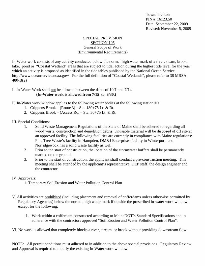
Town: Trenton PIN #: 16123.50 Date: September 22, 2009
Revised: November 5, 2009
SPECIAL PROVISION SECTION 105
General Scope of Work (Environmental Requirements)
In-Water work consists of any activity conducted below the normal high water mark of a river, steam, brook, lake, pond or “Coastal Wetland” areas that are subject to tidal action during the highest tide level for the year which an activity is proposed as identified in the tide tables published by the National Ocean Service. http://www.oceanservice.noaa.gov/ For the full definition of “Coastal Wetlands”, please refer to 38 MRSA 480-B(2) I. In-Water Work shall not be allowed between the dates of 10/1 and 7/14.
(In-Water work is allowed from 7/15 to 9/30.)
II. In-Water work window applies to the following water bodies at the following station #’s: 1. Crippens Brook – (Route 3) – Sta. 180+75 Lt. & Rt. 2. Crippens Brook – (Access Rd. – Sta. 30+75 Lt. & Rt.
III. Special Conditions:
1. Solid Waste Management Regulations of the State of Maine shall be adhered to regarding all wood waste, construction and demolition debris. Unusable material will be disposed of off site at an approved facility. The following facilities are currently in compliance with Maine regulations: Pine Tree Waste’s facility in Hampden, DM&J Enterprises facility in Winterport, and Norridgewock has a solid waste facility as well.
2. Prior to the start of construction, the location of the stormwater buffers shall be permanently marked on the ground.
3. Prior to the start of construction, the applicant shall conduct a pre-construction meeting. This meeting shall be attended by the applicant’s representative, DEP staff, the design engineer and the contractor.
IV. Approvals:
1. Temporary Soil Erosion and Water Pollution Control Plan V. All activities are prohibited (including placement and removal of cofferdams unless otherwise permitted by
Regulatory Agencies) below the normal high water mark if outside the prescribed in-water work window, except for the following:
1. Work within a cofferdam constructed according to MaineDOT’s Standard Specifications and in
adherence with the contractors approved “Soil Erosion and Water Pollution Control Plan”.
VI. No work is allowed that completely blocks a river, stream, or brook without providing downstream flow. NOTE: All permit conditions must adhered to in addition to the above special provisions. Regulatory Review and Approval is required to modify the existing In-Water work window.

Trenton 16123.50 October 30, 2009
SPECIAL PROVISION SECTION 105
General Scope of Work (Permits)
The Contractor shall be responsible for obtaining, at his own expense, the Building Permit for the Bus Maintenance Facility including all other building structures for this project. The permit can be purchased for the amount of $2826.87 at Trenton Town Hall 59 Oak Point Road Trenton, Me 04605 The cost for the Building Permit shall be considered incidental to the Contract.
1 of 1

ROOF ACCESSORIES 07 72 00 - 1 ACADIA GATEWAY BUS MAINTENANCE FACILITY PIN NO. 013332.06 Amendment #6
SECTION 07 72 00 ROOF ACCESSORIES
PART 1 - GENERAL
1.1 RELATED DOCUMENTS
A. If the Contractor discovers any ambiguity, error, omission, conflict, or discrepancy, General Conditions Section 101.3.6 Priority of Conflicting Contract Documents shall control.
1. Drawings and general provisions of the Contract, including General and Supplementary Conditions and other Division 1 Specification Sections, apply to this Section.
2. State of Maine Department of Transportation, “Standard Specifications,” Revision December 2002, and any revisions thereto, apply to this Section.
1.2 DESCRIPTION OF WORK
A. Work Included: This Section specifies the following:
1. Roof hatches.
B. Related Work: The following items are not included in this Section and will be performed under the designated Sections:
1. Section 05 50 00 - MISCELLANEOUS METALS: Metal vertical ladders, ships' ladders, and stairs for access to roof hatches, and from roof to roof.
2. Section 06 10 00 - ROUGH CARPENTRY: Wood cants and wood nailers 3. Section 07 60 00 - SHEET METAL FLASHING AND TRIM: Shop- and field-fabricated metal
flashing and counterflashing, roof expansion-joint covers, and miscellaneous sheet metal trim and accessories.
1.3 SUBMITTALS
A. Product Data: For each type of roof accessory indicated. Include construction details, material descriptions, dimensions of individual components and profiles, and finishes.
B. Shop Drawings: Show fabrication and installation details for roof accessories. Show layouts of roof accessories including plans and elevations. Indicate dimensions, weights, loadings, required clearances, method of field assembly, and components. Include plans, elevations, sections, details, and attachments to other work.
1.4 QUALITY ASSURANCE
A. Sheet Metal Standard: Comply with SMACNA's "Architectural Sheet Metal Manual" details for fabrication of units, including flanges and cap flashing to coordinate with type of roofing indicated.
ROOF ACCESSORIES 07 72 00 - 2 ACADIA GATEWAY BUS MAINTENANCE FACILITY PIN NO. 013332.06 Amendment #6
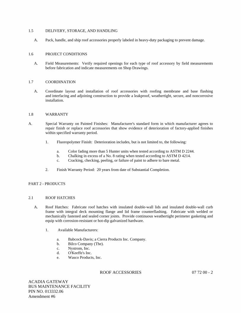
1.5 DELIVERY, STORAGE, AND HANDLING
A. Pack, handle, and ship roof accessories properly labeled in heavy-duty packaging to prevent damage.
1.6 PROJECT CONDITIONS
A. Field Measurements: Verify required openings for each type of roof accessory by field measurements before fabrication and indicate measurements on Shop Drawings.
1.7 COORDINATION
A. Coordinate layout and installation of roof accessories with roofing membrane and base flashing and interfacing and adjoining construction to provide a leakproof, weathertight, secure, and noncorrosive installation.
1.8 WARRANTY
A. Special Warranty on Painted Finishes: Manufacturer's standard form in which manufacturer agrees to repair finish or replace roof accessories that show evidence of deterioration of factory-applied finishes within specified warranty period.
1. Fluoropolymer Finish: Deterioration includes, but is not limited to, the following:
a. Color fading more than 5 Hunter units when tested according to ASTM D 2244. b. Chalking in excess of a No. 8 rating when tested according to ASTM D 4214. c. Cracking, checking, peeling, or failure of paint to adhere to bare metal.
2. Finish Warranty Period: 20 years from date of Substantial Completion.
PART 2 - PRODUCTS
2.1 ROOF HATCHES
A. Roof Hatches: Fabricate roof hatches with insulated double-wall lids and insulated double-wall curb frame with integral deck mounting flange and lid frame counterflashing. Fabricate with welded or mechanically fastened and sealed corner joints. Provide continuous weathertight perimeter gasketing and equip with corrosion-resistant or hot-dip galvanized hardware.
1. Available Manufacturers:
a. Babcock-Davis; a Cierra Products Inc. Company. b. Bilco Company (The). c. Nystrom, Inc. d. O'Keeffe's Inc. e. Wasco Products, Inc.

ROOF ACCESSORIES 07 72 00 - 3 ACADIA GATEWAY BUS MAINTENANCE FACILITY PIN NO. 013332.06 Amendment #6
2. Loads: Fabricate roof hatches to withstand 40-lbf/sq. ft. external and 20-lbf/sq. ft. internal loads. 3. Type and Size: Type S by Bilco or equal, 36” x 36” one-hand operation, or as indicated on the
Drawings. 4. Curb and Lid Material: Galvanized steel sheet, 0.079 inch thick. 5. Insulation: Manufacturer's standard board insulation. 6. Interior Lid Liner: Manufacturer's standard metal liner of same material and finish as outer metal
lid. 7. Exterior Curb Liner: Manufacturer's standard metal liner of same material and finish as metal
curb. 8. Fabricate units to minimum height of 12 inches unless otherwise indicated. 9. Hardware: Galvanized steel spring latch with turn handles, butt- or pintle-type hinge system, and
padlock hasps inside and outside. 10. Ladder Safety Post: Manufacturer's standard ladder safety post. Post to lock in place on full
extension. Provide release mechanism to return post to closed position.
2.2 MISCELLANEOUS MATERIALS
A. Wood Nailers: Softwood lumber, pressure treated with waterborne preservatives for aboveground use, complying with AWPA C2; not less than 1-1/2 inches thick.
B. Bituminous Coating: Cold-applied asphalt mastic, SSPC-Paint 12, compounded for 15-mil dry film thickness per coat. Provide inert-type noncorrosive compound free of asbestos fibers, sulfur components, and other deleterious impurities.
C. Fasteners: Same metal as metals being fastened, or nonmagnetic stainless steel or other noncorrosive metal as recommended by roof accessory manufacturer. Match finish of exposed fasteners with finish of material being fastened. Provide nonremovable fastener heads to exterior exposed fasteners.
D. Gaskets: Manufacturer's standard tubular or fingered design of neoprene, EPDM, or PVC; or flat design of foam rubber, sponge neoprene, or cork.
E. Elastomeric Sealant: ASTM C 920, polyurethane sealant; of type, grade, class, and use classifications required to seal joints in sheet metal flashing and trim and remain watertight.
PART 3 - EXECUTION
3.1 EXAMINATION
A. Examine substrates, areas, and conditions, with Installer present, to verify actual locations, dimensions, and other conditions affecting performance of work.
1. Verify that substrate is sound, dry, smooth, clean, sloped for drainage, and securely anchored and is ready to receive roof accessories.
2. Verify dimensions of roof openings for roof accessories. 3. Proceed with installation only after unsatisfactory conditions have been corrected.

ROOF ACCESSORIES 07 72 00 - 4 ACADIA GATEWAY BUS MAINTENANCE FACILITY PIN NO. 013332.06 Amendment #6
3.2 INSTALLATION
A. General: Install roof accessories according to manufacturer's written instructions. Anchor roof accessories securely in place and capable of resisting forces specified. Use fasteners, separators, sealants, and other miscellaneous items as required for completing roof accessory installation. Install roof accessories to resist exposure to weather without failing, rattling, leaking, and fastener disengagement.
B. Install roof accessories to fit substrates and to result in watertight performance.
C. Metal Protection: Where dissimilar metals will contact each other or corrosive substrates, protect against galvanic action by painting contact surfaces with bituminous coating or by other permanent separation as recommended by manufacturer.
1. Coat concealed side of uncoated aluminum roof accessories with bituminous coating where in contact with wood, ferrous metal, or cementitious construction.
2. Underlayment: Where installing exposed-to-view components of roof accessories directly on cementitious or wood substrates, install a course of felt underlayment and cover with a slip sheet, or install a course of polyethylene underlayment.
3. Bed flanges in thick coat of asphalt roofing cement where required by roof accessory manufacturers for waterproof performance.
D. Install roof accessories level, plumb, true to line and elevation, and without warping, jogs in alignment, excessive oil canning, buckling, or tool marks.
E. Roof Hatch Installation:
1. Check roof hatch for proper operation. Adjust operating mechanism as required. Clean and lubricate joints and hardware.
2. Attach safety railing system to roof hatch curb. 3. Attach ladder safety post according to manufacturer's written instructions.
F. Seal joints with elastomeric sealant as required by manufacturer of roof accessories.
3.3 TOUCH UP
A. Touch up factory-primed surfaces with compatible primer ready for field painting in accordance with Division 9 painting Sections.
B. Galvanized Surfaces: Clean field welds, bolted connections, and abraded areas and repair galvanizing to comply with ASTM A 780.
3.4 CLEANING
A. Clean exposed surfaces according to manufacturer's written instructions.
END OF SECTION

MARKER BOARDS AND PROJECTION SCREENS 101000 - 1 ACADIA GATEWAY BUS MAINTENANCE FACILITY PIN NO. 16123.50 Amendment # 6
PART 1 - GENERAL
1.01 RELATED DOCUMENTS
A. If the Contractor discovers any ambiguity, error, omission, conflict or discrepancy, General Conditions Section 101.3.6 Priority of Conflicting Contract Documents shall control.
1. Drawings and general provisions of the Contract, including General and Supplementary Conditions and other Division 1 Specification Sections, apply to this Section.
2. State of Maine Department of Transportation, “Standard Specifications,” Revision December 2002, and any revisions thereto, apply to this Section.
1.02 DESCRIPTION OF WORK
A. This section includes materials and installation of marker boards and projection screens.
1.03 SUBMITTALS
A. Submit shop drawing in accordance with Section 013300.
B. Submit manufacturer's catalog data and installation instructions showing parts, dimensions, anchorage, connections and relationship to adjacent work.
PART 2 - MATERIALS
2.01 MARKER BOARDS
A. Marker boards shall be wall height laminated panels with 24-gauge LCS skins, mounted on foil backed 3/8-inch particle board, having matched butt joints and joind with steel spline joints for smooth alignment and No. 180 perimeter trim as manufactured by Claridge Products and Equipment, Inc.; Greensteel, Inc., or equal. Boards shall have white writing surface.
B. Size and Location: As indicated in drawings.
2.02 MARKERS
A. Markers shall be Claridge, No. LCS; Greensteel, No. 7900T; or equal. Color of markers shall be assorted. Supply one dozen markers for each marker board specified or shown.
2.03 PROJECTION SCREENS
A. Projection screens shall be SUPRA units as manufactured by Claridge Products and Equipment, Inc.; Greensteel, Inc.; or equal. Screens shall have glass-beaded surface, an automatic ceiling closure and motor operation.
B. Projection surface shall be 96-inches wide x 72-inches high with 24-inches high black fabric panel above projection surface.

MARKER BOARDS AND PROJECTION SCREENS 101000 - 2 ACADIA GATEWAY BUS MAINTENANCE FACILITY PIN NO. 16123.50 Amendment # 6
PART 3 - EXECUTION
3.01 INSTALLATION
A. Install in accordance with manufacturer's recommendations. Furnish and install all structural supports including those necessary to accommodate seismic forces, support the weight of all components plus 100 pounds, and to conform to all local requirements.
END OF SECTION 101000


A7
2' - 1"
1' - 4"
8"
8"
6" 6"
OVERHEAD DOOR, SEE ARCH
L1 1/2x1 1/2x1/4 (GALV) STEEL
CURB ANGLES ANCHORED TO
SLAB
1/4"/FT SLOPE
3/4" CHAMFER TYP
AT EXPOSED EDGES
1' - 6"
1' - 0"
1' - 0"
1' - 6"
6"
1/2"
1/2"
#4 BARS @ 12"O.C.
EACH WAY
(2)#4 BARS CONT
FULL PERIMETER
#4 BARS @ 12"O.C.
(ALL 4-SIDES)
#6 BARS x 3'-0"LONG
@ 12"O.C.
2" RIGID INSULATION
SEE DETAIL E7/SB-500
FOR WALL AND FOOTING
REINFORCING
SLAB-ON-GRADE - SEE
PLAN
ROUGHEN SURFACE, TYP.
RADIANT PIPING ON
INSULATED FLOOR
PANEL SYSTEM
RADON PIPING
UNDER-
DRAIN
4" RIGID INSUL
UNDER APRON, TYP.
RADIANT HEAT PIPING IN SLAB
(1-1/2" CLR)
Scale:
Date:CAD File:
Project No: 3/4" = 1'-0"07010
10/28/09
SKS-01
ACADIA GATEWAY FACILITY
REVISED DETAIL E3/SB-500
07010S.rvt
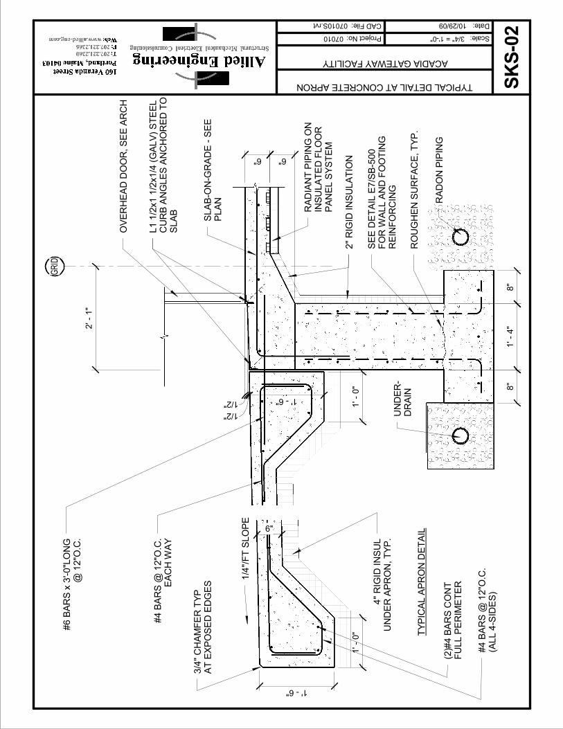
A7
2' - 1"
1' - 4"
8"
8"
6" 6"
OVERHEAD DOOR, SEE ARCH
L1 1/2x1 1/2x1/4 (GALV) STEEL
CURB ANGLES ANCHORED TO
SLAB
1/4"/FT SLOPE
3/4" CHAMFER TYP
AT EXPOSED EDGES
1' - 6"
1' - 0"
1' - 0"
1' - 6"
6"
1/2"
1/2"
#4 BARS @ 12"O.C.
EACH WAY
(2)#4 BARS CONT
FULL PERIMETER
#4 BARS @ 12"O.C.
(ALL 4-SIDES)
#6 BARS x 3'-0"LONG
@ 12"O.C.
2" RIGID INSULATION
SEE DETAIL E7/SB-500
FOR WALL AND FOOTING
REINFORCING
SLAB-ON-GRADE - SEE
PLAN
ROUGHEN SURFACE, TYP.
RADIANT PIPING ON
INSULATED FLOOR
PANEL SYSTEM
RADON PIPING
UNDER-
DRAIN
TYPICAL APRON DETAIL
4" RIGID INSUL
UNDER APRON, TYP.
GRID
Scale:
Date:CAD File:
Project No: 3/4" = 1'-0"07010
10/29/09
SKS-02
ACADIA GATEWAY FACILITY
TYPICAL DETAIL AT CONCRETE APRON
07010S.rvt