Embed Size (px)
Citation preview
16/03/2013
1
MME 467 Ceramics for Advanced Applications
Lecture 07
Deformation Behaviour and Strength of Ceramic Materials Ref: Kingery, Introduction to Ceramics, Ch14, John Wiley & Sons, 1991
Prof. A. K. M. Bazlur Rashid Department of MME, BUET, Dhaka
Topics to discuss....
1. The plastic deformation 2. Deformation behaviour in ceramics
3. Strength of ceramics
4. Processing and surface flaws
4. Effects of flaws on strength of ceramics

16/03/2013
2
The plastic deformation
� Irreversible deformation of materials The remains of deformation after unloading in a tensile or compression test
� Mechanisms responsible for plastic deformation
Dislocation motion Vacancy motion Twining Phase transformation Viscous flow (in amorphous materials)
� For polycrystalline or multiphase materials
Deformation occurs within grains (transgranular) or along the grain boundaries (intergranular)
Motion of dislocation in materials (Ashby)
� In metals, dislocation motion is intrinsically easy Deformation can occur even at room temperature by dislocation motion
� For ceramics, high shear stress required for dislocation motion.
q With covalent ceramics dislocation motion is difficult due to the necessity to break and reform the strong bonds
q With ionic ceramics difficulty in dislocation motion is related to the distribution of charges in the crystal structure
� Thus, most failure in ceramics occurs by the extension of flaws.

16/03/2013
3
� Plastic deformation at room temperature involves slip between the planes of atoms under the influences of an applied stress. Theoretical stress needed to cause slipping of one complete plane with respect to the adjacent plane is about E/15.
� The presence of dislocation and the associated residual stress allows slip to occur along atom planes at a fraction of E/15 value that would be required in the absence of dislocations. For example, 99.97% purity nickel (for which E= 214 GPa) begins to plastically deform at room temperature at about 110 MPa
� A single dislocation does not result in significant plastic stress within a material Under an applied stress, dislocations can form and multiply Typical deformed metals may contain millions of dislocation per cubic centimetre
� Actual slip occurs in bands along preferred crystal planes Preferred planes for HCP structures is (0001), while several families of slip planes exists for cubic close packed structures: {111}, {100}, and {100}
Ways of inhibiting dislocation motion
1. forming solute solution 2. including inclusions or precipitates in the structure 3. increasing grain boundaries 4. increasing work hardening

16/03/2013
4
Deformation behaviour in ceramics
� Ductile behaviour has been observed in some single-crystal ceramics at room temperature and in some polycrystalline ceramics at elevated ceramics.
� Criteria for plastic deformation in ceramics are the same as for metals: 1. presence of dislocations 2. mechanism of generating new dislocations under an applied stress 3. path along which dislocation can move at a stress lower than the fracture strength
of the ceramics.
Deformation in single crystal ceramics
� Rocksalt [NaCl, KCl, KBr, LiF, MgO] and fluorite [CaF2, UO2] cubic structures show some degrees of deformation
� Rocksalt structure: Slip occurs along {110} planes in [110] directions
Fig. 4: Slip for crystals with rocksalt structure In the <110> direction on (a) {110} plane, (b) {100} plane. {110}<110> glide is preferred.
(a) (b)
The motion involved a minimum distance of slip to restore the original structural arrangement Ions of similar polarity remain at maximum distance from each other, in order to avoid having to overcome a large repulsion energy barrier
� Thus, plastic deformation will not occur unless 1. electrostatic balance is retained 2. structural geometry is not altered 3. cation-anion ratio is maintained
16/03/2013
5
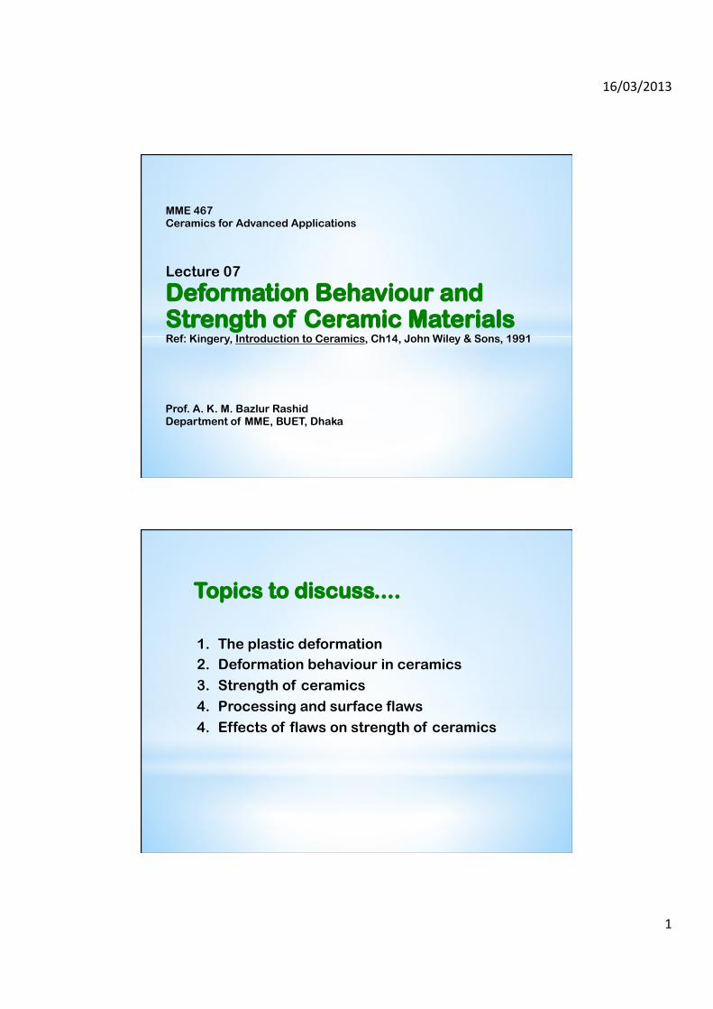
Fig.5: Stress-strain curve for KBr and MgO single crystals tested in bending
Fig.6: Effect of solute concentration on stress-strain curve of MgO-NiO system
� Limited plastic deformation through dislocation motion can also occur in more complex, less symmetrical single crystals ceramics.
v Yield stress is much higher v mechanism of slip is more complex and restrictive
� Materials fracture in brittle manner with no plastic deformation at low temperatures.
� Slip only occurs at high temperatures where additional dislocation motions become energetically possible.

16/03/2013
6
Example: Deformation in Al2O3 single crystals
Fig. 8: Crystal structure of Al2O3 showing complex paths O and Al ions must follow to allow to slip to occur under an applied stress.
� Movement of O-2 ion from position 1 to 2
1. Using route 1-b-2
2. Using route 1-b’-3-b”-2 involving stacking faults within the structure
� Movement of Al+3 ion
through complex routes of b1’-b2’-b1”-b2”
� High stress required for initial yield
� Less strain required to
sustain deformation
Fig. 9: Stress-strain diagrams of single crystal Al2O3 At various temperatures and strain rates
� Yield stress is less at higher temperatures and at low strain rates
16/03/2013
7
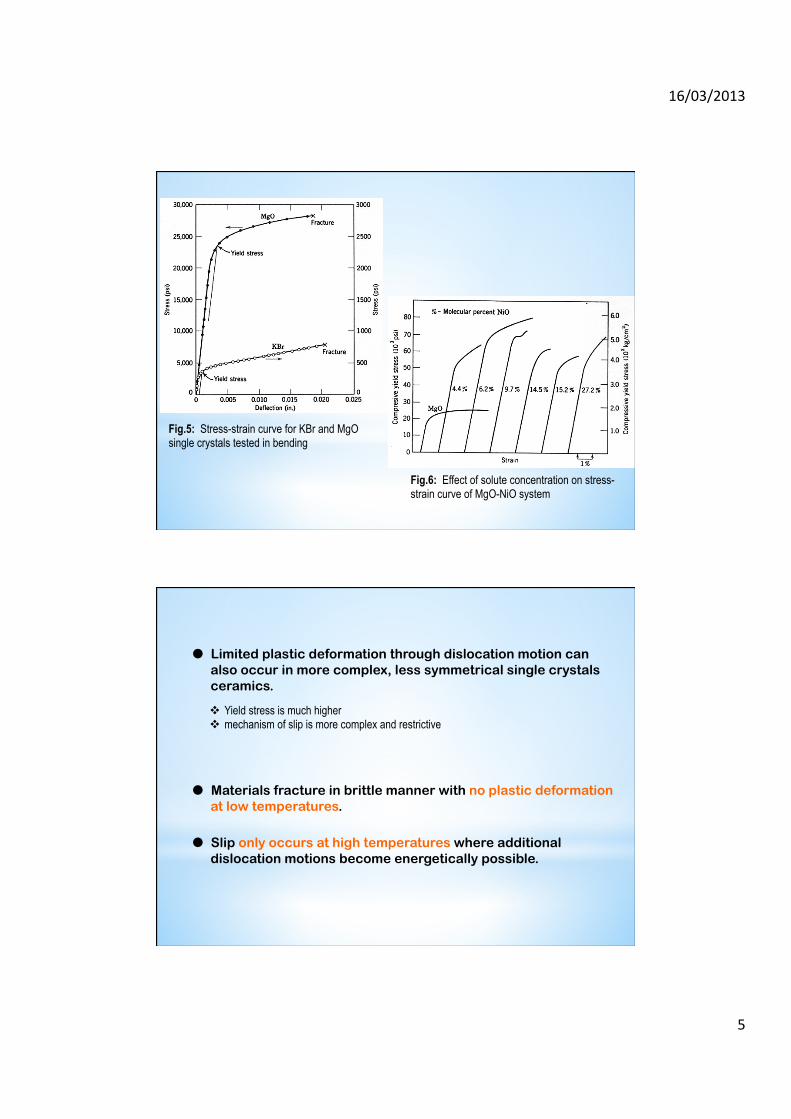
Deformation in polycrystalline ceramics
� Polycrystalline materials are generally found to be harder than those having single crystals Generally fractures in brittle mode at room temperatures
� Random grain orientations with respect
to applied stress causes differences in alignment of the slip lines makes slipping more complex.
� For plastic deformation to occur, five independent slip systems must be present in the crystal structure At room temperature, most ceramics have three or less slip systems.
� A few ceramics have five slip systems at high temperatures
NaCl, LiF, MgO, NaF, TiC, UC, diamond, CaF2, UO2, and MgAl2O4
Slip lines in deformed polycrystalline Copper
Material
Crystal structure
Slip systems
No. of associated independent slip systems
Temperature for appreciable slip (°C )
Primary
Secondary
Primary
Secondary
Primary
Secondary
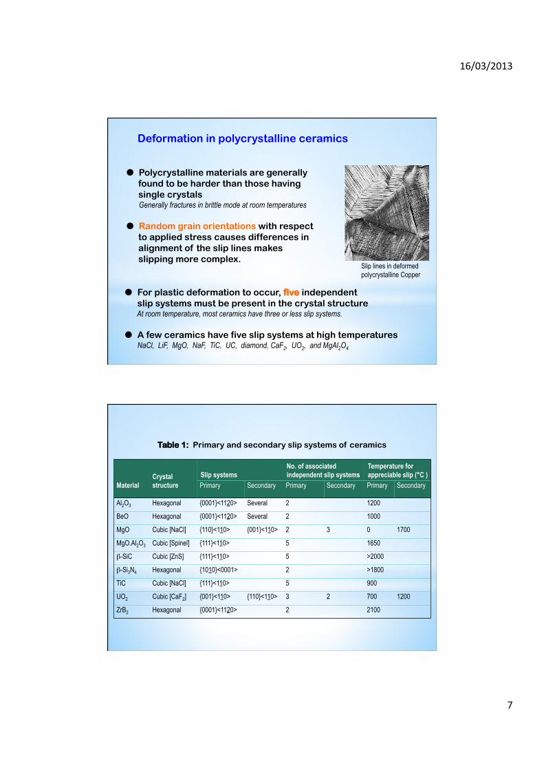
Al2O3 Hexagonal {0001}<1120> Several 2 1200
BeO Hexagonal {0001}<1120> Several 2 1000
MgO Cubic [NaCl] {110}<110> {001}<110> 2 3 0 1700
MgO.Al2O3 Cubic [Spinel] {111}<110> 5 1650
β-SiC Cubic [ZnS] {111}<110> 5 >2000
β-Si3N4 Hexagonal {1010}<0001> 2 >1800
TiC Cubic [NaCl] {111}<110> 5 900
UO2 Cubic [CaF2] {001}<110> {110}<110> 3 2 700 1200
ZrB2 Hexagonal {0001}<1120> 2 2100
Table 1: Primary and secondary slip systems of ceramics
16/03/2013
8
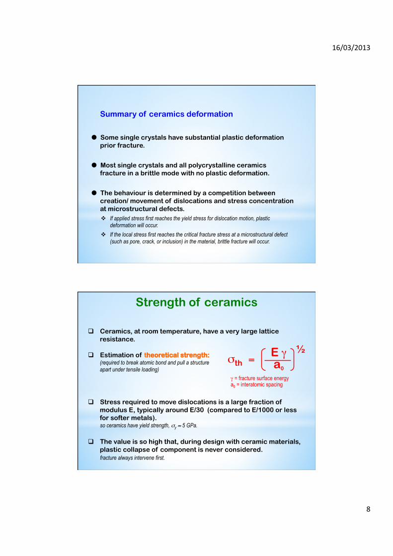
Summary of ceramics deformation
� Some single crystals have substantial plastic deformation prior fracture.
� Most single crystals and all polycrystalline ceramics fracture in a brittle mode with no plastic deformation.
� The behaviour is determined by a competition between creation/ movement of dislocations and stress concentration at microstructural defects. v If applied stress first reaches the yield stress for dislocation motion, plastic
deformation will occur. v If the local stress first reaches the critical fracture stress at a microstructural defect
(such as pore, crack, or inclusion) in the material, brittle fracture will occur.
Strength of ceramics
E γ a0
½ σth =
γ = fracture surface energy a0 = interatomic spacing
q Ceramics, at room temperature, have a very large lattice resistance.
q Stress required to move dislocations is a large fraction of modulus E, typically around E/30 (compared to E/1000 or less for softer metals). so ceramics have yield strength, σy ≈ 5 GPa.
q The value is so high that, during design with ceramic materials, plastic collapse of component is never considered. fracture always intervene first.
q Estimation of theoretical strength: (required to break atomic bond and pull a structure apart under tensile loading)

16/03/2013
9
q The penalty of having a large lattice resistance in ceramics is brittleness.
l this results a low fracture toughness, KIC , i.e., the amount of energy absorbed during fracture (even at the crack tip) is low
q Thus, ceramics have fracture toughness, KIC, values roughly 1/5th of those good, ductile metals.
So, why do ceramics have such low values of strength and fracture toughness ?
Material E, GPa
Estimated theoretical
strength, GPa
Measured strength of fibers, GPa
Measured strength of
polycrystalline specimen, GPa
Al2O3 380 38 16 0.40
SiC 440 44 21 0.70
Table 2: Comparison of theoretical strength and actual strength
q Some sources of flaws: u Manufacturing process (e.g., pores during sintering, hairline cracks during machining, etc.) v Thermal stress during cooling or thermal loading (internal cracks) w Corrosion (often by water) or abrasion (by dust) at the surface x During loading (internal/surface cracks)
Microstructure of typical ceramic showing cracks and other flaws
Processing and surface flaws
q Ceramic materials always have a reduced strength and fracture toughness, because they almost always contains internal or surface cracks and other flaws.
16/03/2013
10
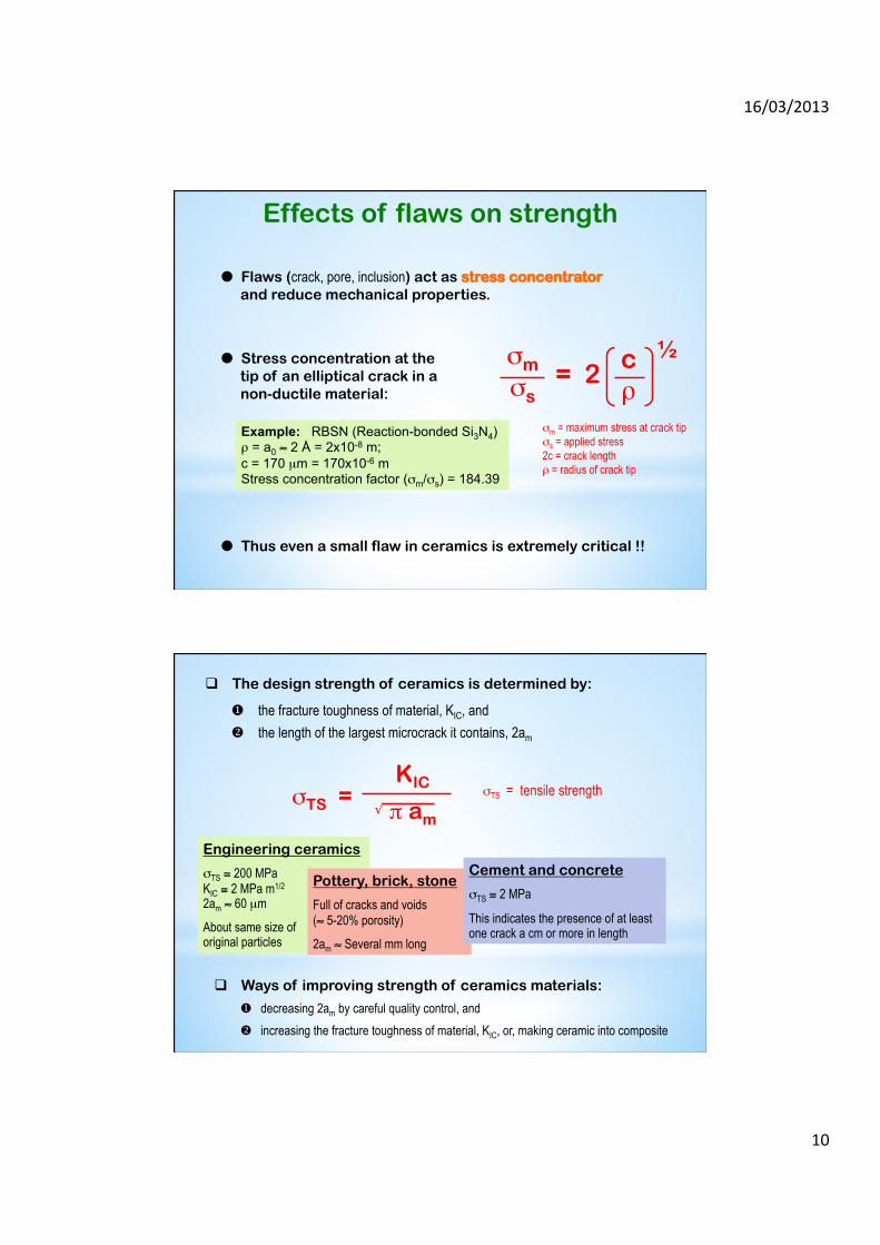
Effects of flaws on strength
� Flaws (crack, pore, inclusion) act as stress concentrator and reduce mechanical properties.
� Stress concentration at the tip of an elliptical crack in a non-ductile material:
c ρ
½ σm σs = 2
σm = maximum stress at crack tip σs = applied stress 2c = crack length ρ = radius of crack tip
Example: RBSN (Reaction-bonded Si3N4) ρ = a0 ≈ 2 Å = 2x10⁻⁸ m; c = 170 µm = 170x10-6 m Stress concentration factor (σm/σs) = 184.39
� Thus even a small flaw in ceramics is extremely critical !!
q The design strength of ceramics is determined by:
u the fracture toughness of material, KIC, and v the length of the largest microcrack it contains, 2am
σTS = KIC
π am √
σTS = tensile strength
Engineering ceramics
σTS ≅ 200 MPa KIC ≅ 2 MPa m1/2
2am ≈ 60 µm
About same size of original particles
Pottery, brick, stone
Full of cracks and voids (≈ 5-20% porosity)
2am ≈ Several mm long
Cement and concrete
σTS ≅ 2 MPa
This indicates the presence of at least one crack a cm or more in length
q Ways of improving strength of ceramics materials:
u decreasing 2am by careful quality control, and v increasing the fracture toughness of material, KIC, or, making ceramic into composite
16/03/2013
11
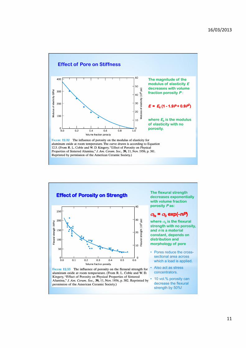
The magnitude of the modulus of elasticity E decreases with volume fraction porosity P :
E = E0 (1 - 1.9P + 0.9P2)
where E0 is the modulus of elasticity with no porosity.
Effect of Pore on Stiffness
Effect of Porosity on Strength The flexural strength decreases exponentially with volume fraction porosity P as:
σfs = σ0 exp(-nP) where σ0 is the flexural strength with no porosity, and n is a material constant, depends on distribution and morphology of pore
• Pores reduce the cross-sectional area across which a load is applied.
• Also act as stress concentrators.
• 10 vol.% porosity can decrease the flexural strength by 50%!

16/03/2013
12
Severity of strength reduction by porosity depends on:
1. shape of pore
2. presence of crack/grain boundary adjacent to a pore
3. distance between pores and between pore and surface
4. size and shape of inclusion
5. difference in elastic moduli and coefficients of thermal expansion between inclusion and matrix
Pore shape effect
q Spherical pores are less effective than sharp crack as stress concentrator
q Most pores in ceramics are highly irregular in shape
q Models to relate flaw size to fracture stress assume pores as elliptical crack
Pore-crack combination effect
q Common case is intersection of pores with grain boundaries
q If the pore is much larger than grain Edge of pore determines the critical flaw size
q If pore and grains are equal Crack generates along the boundary and the effective flaw size will be larger than the pore
16/03/2013
13
Internal pores
q Shape and position of pore with respect to surface affects strength
q If the pore is close to the surface, the following Ligament Theory applies: v Breaking the bridge/ligament of material separating it from the surface will result a
critical flaw with dimension equals pore size plus bridge thickness v Strength value will be between those of materials having pores alone and having
pores intersecting the surface v Internal pores within about half the radius of pores from the surface follow this theory,
and the resulting calculated strength is within 10% of the measured value
Pore clusters
q When a group of pores are close together, the breaking of bridging materials between them produces a much larger flaw Strength reduces considerably
q Pores separated by less than one pore radius will link.
q Should be avoided during forming: Agglomeration Exaggerated grain growth

16/03/2013
14
Inclusions
q Occurs through contaminations of ceramic powders
q Degree of reduction of strength by an inclusion depends on: v Thermal and elastic properties of inclusion compared to the matrix material
q Difference in thermal expansion, α v Results cracks adjacent to the inclusion during cooling v Residual stresses generated are directly proportional to (αm - αi) and ∆T
q Difference in elastic modulus v Results crack when a load is applied
q Worst case scenario: v Inclusions with low coefficient of thermal expansion and low elastic modulus
compared to the matrix v Effective flaw size is larger than the visible inclusion size, being equivalent to
inclusion plus length of adjacent crack
q Inclusions having higher expansion and modulus: v Have less effect on strength v Produces circumferential cracks, rather than radial crack v Effective flaw size is like a flat elliptical crack whose size is equivalent to the
elliptical dimensions of the inclusion

16/03/2013
15
q Resulted due to v High-temperature grooving v Post-fabrication operations v Accidental damage during service
q Cracks generally not extended beyond a grain before arresting at the grain boundary v Fracture strength increases as grain size decreased (Griffith criterion)
q Flaws propagated through a grain v Along cleavage planes v Along grain boundaries
Surface flaws
q Strength is inversely proportional to grains size. v Flaw size decreases as grain size is decreased v Flaws formed at the grain boundary,
propagates up to about one grain diameter q For very fine-grained ceramics
v Fracture occurs from pre-existing process/surface flaws
v Strength becomes relatively grain size insensitive
Grain size

16/03/2013
16
q Use of a compressive surface layer v compressive surface residual stress inhibits failure from surface flaw, since this
stress has to be overcome before crack propagation v strengthen ceramic materials, increases shock resistance and contact damage
resistance q Basic principle:
To generate a surface layer with a higher volume than the original matrix
Compressive surface residual stresses
q Common methods: 1. Incorporating an outer layer with lower coefficient of thermal expansion
(glaze technology, tempering in glass) 2. Using transformation stresses (zirconia ceramics) 3. Physically stuffing outer layer with ions/atoms (ion implantation) 4. Ion exchanging (smaller ions for larger ions)
q Due to this outer compressive layer, a tensile stress is developed at the inside of material
v If any flaw propagates through the compressive layer, material fails more easily than the materials without a compressive layer.
v E.g., Tempered glass for car wind shield (release of residual stresses cause the glass to shatter)
16/03/2013
17
Temperature / atmosphere
q Depend on whether or not the atmosphere heals or aggravates pre-existing surface flaws
q Corrosive atmosphere at high temperature
1. forms protective (usually oxide) layer on the surface; blunts and partially heals the flaws; improves strength 2. attacks the surface; forms pits, or simply etching the surface away; strength decreases
q Ceramics containing glassy grain boundary phases
v Softening of phase occurs; strength decreases.
Next Class
Lecture 08
Fracture Toughness and Toughening Mechanisms