Embed Size (px)
Citation preview
Deflections and Construction
Tolerances: The Good, The Bad, & The
Ugly
ACI Spring Convention – Denver, CO
ACI Committees 117 & 435
Planning for the Control of
Construction Tolerances and
Deflections
James McHugh Construction Co.
Chicago, IL

• Contractors want to build fast, safe and
efficiently with the least amount of remedial
work as possible.
• Disconnect between division 3 and
divisions 8 & 9 of project specifications
• Engineers designing buildings that are
more efficient, slender, thinner, lightly
reinforced, more highly stressed and more
susceptible to deflection and creep
• Higher expectation of design team and
owners for dimensional tolerance.
Introduction

• Definition of project tolerances, ACI 117
• Building variation • SLAB DEFLECTION
• SLAB SHORTENING
• COLUMN SHORTENING
• POTENTIAL CONFLICTS BETWEEN
STRUCTURE AND CLADDING• Window wall system needs to accommodate
the additional long term deflections.
• FLOORING
• Review of project specifications
• Formed face finish requirements
Pre-Construction

4
Slab Performance Criteria
ACI 318 vs Division 9
Structural
Engineers
utilize ACI 318
Ch 9 T. 9.5(b)
Owners are expecting
1/8 inch in 10ft from
level

Excessive deflections that exceed ACI318 Ch 9 and/or
Division 9 specifications can result in costly remedial
measures such as:
•Placing a latex modified concrete leveling topping.
•Modifications and/or repairs to exterior cladding.
•Repair of damage to interior partitions & finishes.
•Repair/replacement of poorly performing floor finishes such
as hardwood flooring.
•WINDOWS
•ALIGNMENT OF DOORS IN HALLWAYS
•KITCHEN CABINETS & COUNTERTOPS
•BACK PITCHING OF BALCONIES
•ELEVATOR DOOR FRAMES
•Window head and sill trim highlight deflections
Slab Deflection Problems
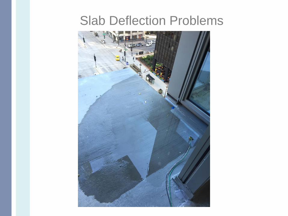
Slab Deflection Problems

CLADDING
WINDOW WALL
BRICK
ESTHETIC OF EXPOSED CONCRETE AT WALLS,
COLUMNS, WHERE PLUMB WINDOWS MEET LEANING
COLUMNS/WALLS
WINDOW FRAMES HIGHLIGHT SLAB SHORTENING
ISSUES
Slab SHORTENING Problems

Slab SHORTENING Problems

Slab SHORTENING Problems

Slab SHORTENING Problems

•WINDOWS
•ALIGNMENT OF DOORS IN HALLWAYS
•KITCHEN CABINETS & COUNTERTOPS
•ELEVATOR DOOR FRAMES
•DISTRESS AT CONNECTION BETWEEN COLUMN/WALL
AND SPANDRELS
Column Shortening Problems

Column Shortening Problems
WHAT CONTRACTORS WANT…
•Contractors want to build FAST!
•Plan work to proceed safely on a fast efficient
schedule.
•Delivers a structure to the client that meets all
project specifications
• Divisions 3, 8 & 9 of project specs
•And of course get paid!
• No costly remedial work or disagreements
of work non-compliance.
• In the State of Illinois, the Statute of
Repose is 10 years. That’s a long time!
Contractor’s Perspective

WHAT CONTRACTORS DO TO INFLUENCE/
IMPROVE SLAB DEFLECTION
PERFORMANCE…
•Selection of formwork system.
•Construction equipment (such as tower crane,
concrete pumps & placement booms).
•Mix design.
•Hot weather/cold weather construction
methodologies
•Location of pour breaks/construction joints.
•Rate of construction.
•QA/QC program
•Curing conditions
Contractor’s Perspective

– Estimating team price in tolerance issues
– Contract clarifications identify tolerance conflicts
and attempt to allocate responsibility appropriately• Managing client expectations
Coordination of tolerances with other trades
Discussion of anticipated slab deflection, slab
edge shortening, column shortening, lateral
building deflection & story drift with SEOR
Review of construction means and methods,
schedule and budget with regards to
project tolerances and deflection
Pre-Construction

?
PATENTED
MCHUGH RFI
LAUNCHER!

Field layout
• 2D ACAD VS
BIM MODEL
ConstructionBIM MODEL
2D ACAD
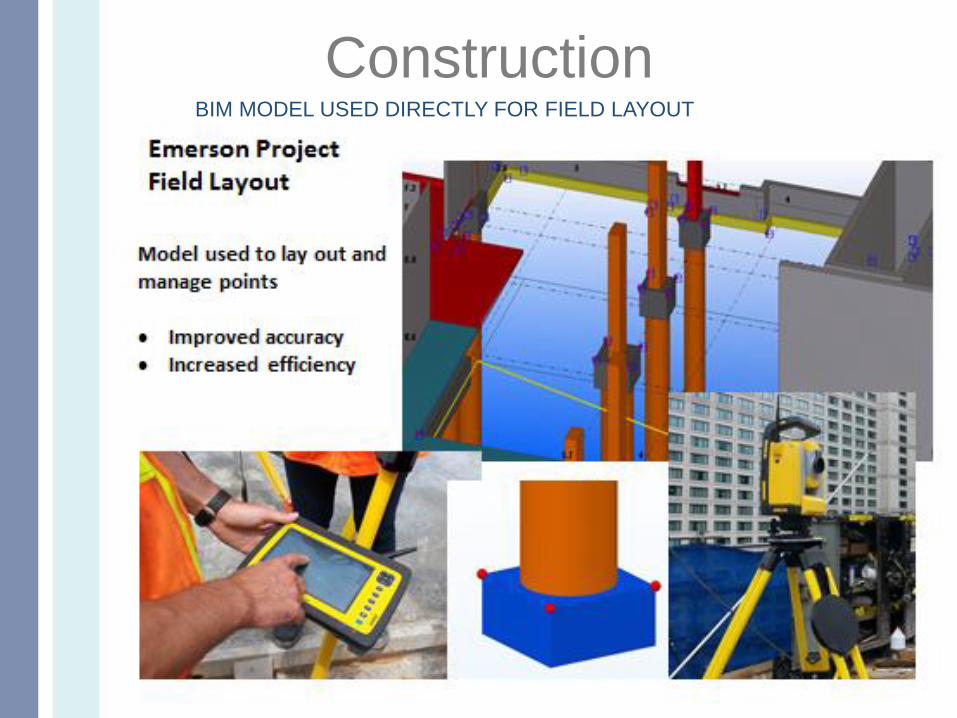
ConstructionBIM MODEL USED DIRECTLY FOR FIELD LAYOUT

FIELD LAYOUT
• BENCHMARK OUTSIDE BUILDING
• CONTROL LINES
• < 20 STORIES, ESTABLISH CONTROL LINES BY
PUTTING STICKER TARGETS ON SURROUNDING
BUILDINGS AND COORDINATING THEM.
• >20 STORIES, BUILDING SWAY BECOMES TOO
GREAT. USE “BOMB SITE” TO BRING THE CONTROL
POINTS UP EVERY 7 FLOORS. BACK CHECKED TO
OUTSIDE.
• CONFLICTING CONTROL LINES BETWEEN CONCRETE
AND OTHER TRADES
• EVERYONE USES CONCRETE’S CONTROL LINES
EXCEPT WINDOW CLADDING COMPANY
Construction

MONITORING PROGRAMS
Formed surface finish quality
Slab Deflection
Slab FF & FL
Column shortening
Slab monitoring program
Top of slab vs bottom of slab
Numbers of shots vs Location
When is data taken:
1.Top formwork prior to concrete placement
2.Top of slab immediately after concrete placement
3.After PT stressing and release of shores
4.After all shoring and reshoring removed
5.Perimeter bottom of slab to validate window wall RO
6.Edge of slab to identify potential curtainwall issues
Construction

MONITORING PROGRAMS
• Accuracy of survey data, whose control
lines??
• Tolerance of slab thickness
• Purpose
• Interpretation of Data
• Comparison of field data to SEOR
predicted short term slab deflection to
identify a problem that can be fixed on
subsequent floors
Construction

CASE STUDY
Overall Project Description
• Location: Downtown Chicago
• 50 Story R/C Residential Tower
• 505’ Height
• 674,750 sq ft
• Level 1 - 14: Retail, Lobby, Parking & Amenity level
• Level 15 - 50: Residential Levels
• 18 months construction period.

• 8” - 2-way RC flat plate
• 10,500 sq ft area
• Maximum clear span:– Exterior Panels: 22.58’ (ln/h=33.9)
– Interior Panels:23.75’ (ln/h=35.6)
• f’c=5000psi
• Typ. #4 & #5 Gr.60 reinforcing bars
• Cover : 1” top and ¾” bottom
• Design Loads– Superimposed Dead Load: 25psf
– Live Load: 40psf
• ACI318-05 T.9.5c Slab Rqd. Thickness: 9”
Typical Residential Floor (Levels 14-50)

Typical Residential Floor (Levels 14-50)
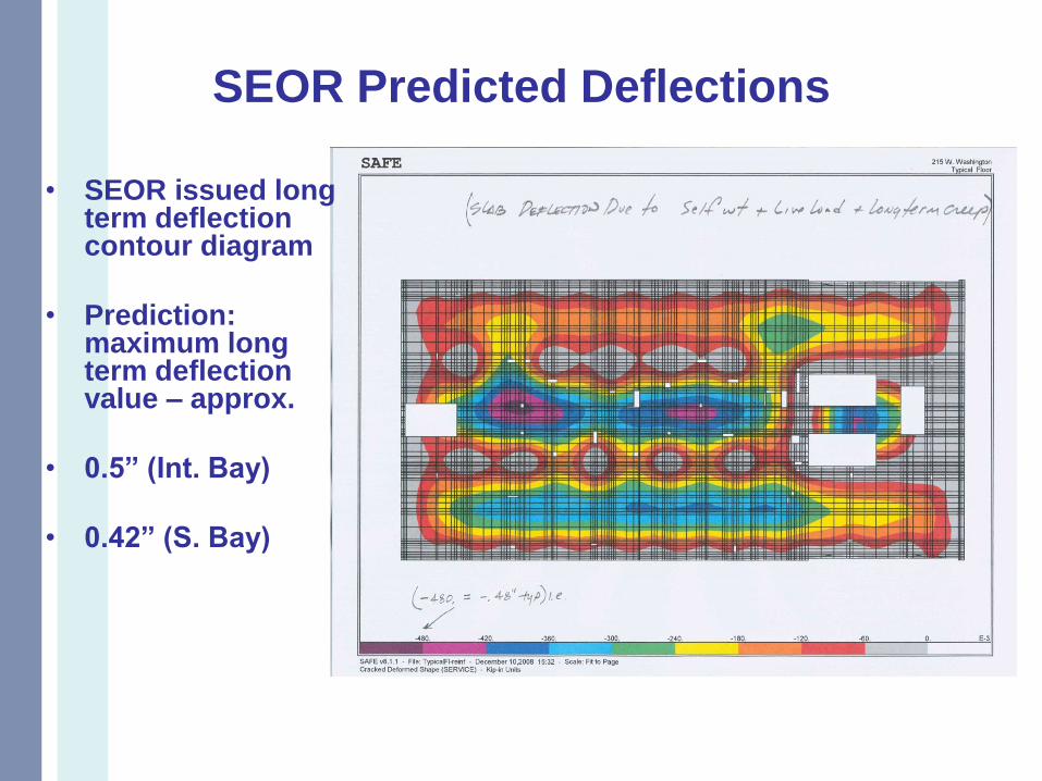
SEOR Predicted Deflections
• SEOR issued long term deflection contour diagram
• Prediction: maximum long term deflection value – approx.
• 0.5” (Int. Bay)
• 0.42” (S. Bay)

McHugh Slab Deflection Study
• Independent Deflection Study
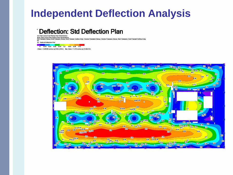
Independent Deflection Analysis

• Max estimated long term deflection
• 1.0” (Int. Bay)
• 0.9” (S. Bay)
Independent Deflection Analysis

Field Measurement of Slab Deflections
• 2 top of slab elevs taken at 84 points on each typ. floor slab
• 1st meas. taken 1 day after placement
with full shoring
• 2nd meas. taken approx. 1 month after placement with no shoring/reshoring
• 6048 Field Measurements
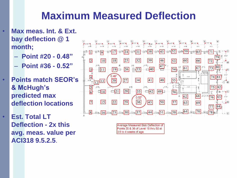
Maximum Measured Deflection
• Max meas. Int. & Ext.
bay deflection @ 1
month;
– Point #20 - 0.48”
– Point #36 - 0.52”
• Points match SEOR’s
& McHugh’s
predicted max
deflection locations
• Est. Total LT
Deflection - 2x this
avg. meas. value per
ACI318 9.5.2.5.

Comparison of Predicted vs. Observed
Numerical Prediction Measured Projected
Point # SEOR
Model
LT D
Independent Analysis LT D
Field Meas D
(@1month)
Projected
Field
LT D (2x Field
Meas)
20 0.50” 1.01” 0.48” 0.96”
36 0.42” 0.93” 0.52” 1.04”
Based upon this independent analysis, McHugh suggested slab
camber to be provided for slabs at locations of maximum
deflection
Bathrooms and large format tile
• The latest thing. Very unforgiving.
• One client requested separate FF
numbers for bathrooms, even though the
minimum sample size is 10’x10’
• Finishing @ toilet and tub penetrations
– Estimators need to carry these $$

Details that potentially vanish
within acceptable tolerances.• Balcony depressions and
window wall interface.
• Sloped PT balcony may back
pitch over time.
• Façade features – long term
risk if coverage not within
tolerance.

Fine Architectural details challenging for a
formwork carpenter on a 3 day pour cycle.
• Unreasonable client expectations

Even with a significant pre-
construction effort, there may be
surprises.
• i.e. Window system arrives on-site
which don’t match the shop dwgs!

Conclusions
• Better planning for deflections and
tolerances = Less Remedial Work =
Cost Savings = Happy Repeat Client!
• Buy the same tolerances from all
trades!
• Communication is the key to success!

QUESTIONS?
THANK YOU!!