Embed Size (px)
Citation preview
DEFLECTION OF BEAMS WlTH SPECIAL
REFERENCE TO SHEAR DEFORMATIONS
THE INFLUENCE OF THE FORM OF A WOODENTHE INFLUENCE OF THE FORM OF A WOODEN
BEAM ON ITS STIFFNESS AND STRENGTH-IBEAM ON ITS STIFFNESS AND STRENGTH-I
Information Reviewed and Reaffirmed
(REPRINT FROM NATIONAL ADVISORY COMMITTEE(REPRINT FROM NATIONAL ADVISORY COMMITTEE
FOR AERONAUTICS REPORT 180, 1924)FOR AERONAUTICS REPORT 180, 1924)
March 1956
No. 1309
DEFLECTION OF BEAMS WITH SPECIAL REFERENCE TO SHEARDEFORMATIONS. *
By J. A. NEWLIN AND G. W. TRAYER.
INTRODUCTION.
This publication is one of a series of three reports prepared by the Forest Products Labora-tory of the Department of Agriculture for publication by the National Advisory Committee forAeronautics. The purpose of these papers is to make known the results of tests to determinethe properties of wing beams of standard and proposed sections, as conducted by the ForestProducts Laboratory and financed by the Army and the Navy.
Many of the mathematical operations employed in airplane design are nothing more thanthe solution of equations which are either empirical or are based on assumptions which areknown to be inaccurate, but which have been adopted because of their simplicity. Theseinaccuracies of the formulas were not of primary consideration as long as the stresses used fordesign were obtained by the test of specimens of the same form as those to be used, and greatrefinement was not necessary.
The advent of the airplane and the impetus given to its development by the recent war hascreated a demand for more definite knowledge of the limitations and proper application of thecommon theory of flexure. There is probably no other field in which greater refinement in thedesign of wooden members is required than in that of aircraft construction. The ever-presentproblem of weight reduction has led to the use of comparatively small load factors and theintroduction of such shapes as are not commonly used for other construction purposes. Formulaswhich give comparable results when applied to wooden beams of rectangular section have beenfound to be considerably in error when applied to wooden beams of other shapes.
The tests were made at Madison, Wis., in cooperation with the University of Wisconsin.An analysis of the results of these tests has furnished information which, when correlated withthat from other studies conducted by the Forest Service for the past 18 years, provided a moreexact method of computing the stiffness of wood beams and led to the development of formulasfor estimating the strength of beams of any cross section, using the properties of small rec-tangular beams as a guide.
For convenience, the report of this investigation has been divided into three parts. Thefirst part deals with the deflection of beams with special reference to shear deformation, whichusually has been neglected in computing deflections of wood beams. The second part has to dowith stresses in beams subjected to transverse loading only, with a subdivision on nonsymmetricalsections; and the third part, with stresses in beams subjected to both longitudinal thrust andbending stresses.
SUMMARY.
In addition to the deflection due to the elongation and compression of fibers from bendingstresses, there is a further deflection due to the shear stresses and consequent strains in a beam.This is not usually considered in computing deflections of wood beams, though the modulusof elasticity in shear for wood is relatively low, being but approximately one-sixteenth themodulus of elasticity in tension and compression, whereas for steel, for example, it is abouttwo-fifths the ordinary modulus.
3*Reprint of Report 180 of the National Advisory Committee for Aeronautics.
1309

4 REPORT NATIONAL ADVISORY COMMITTEE FOR AERONAUTICS.
By neglecting the deformation due to shear, errors of considerable magnitude may beintroduced in determining the distortion of a beam, especially if it is relatively short, or hascomparatively thin webs as the box or I beams commonly used in airplane construction. Agreat many tests were made to determine the amount of shear deformation for beams of varioussections tested over many different spans. As the span over which the beam is tested is in-creased the error introduced by neglecting shear deformations becomes less, and the valuesobtained by substituting measured deflections in the ordinary formulas approach more nearlythe modulus of elasticity in tension and compression. For short spans, however, the erroris considerable, and increases rapidly as the span is reduced. This variation is illustrated inFigures 3 and 4.
The modulus of elasticity in shear was found to vary greatly according to the directionof the grain of the ply wood in webs of box beams. It was found to be over three and one-halftimes as great for beams having ply-wood web with the grain at 45° to the length as for beamshaving webs the face grain of which was perpendicular to the length of the beam.
Two formulas were developed for estimating the magnitude of shear deformations, bothof which have been verified by tests. It is known that the distribution of stress assumed inboth formulas does not exactly represent the actual distribution of stress in a beam. Bothformulas check experimental results very closely when the calculations are made with greatrefinement. It is not known which is the more accurate formula under these conditions, sincethe difference in results obtained by the two is only a small part of the normal variation ofthe material. The first formula, with its high powers and numerous factors, will obviouslylead one into inaccuracies due to the ordinary approximations used in calculations more readilythan will the second, or similar formula. In both formulas the deformation due to shear is
equal to where P is the load on a beam of length l, F is the modulus of elasticity in shear,
and K is some coefficient depending upon the shape of the beam and upon the loading. Theformulas differ only in the determination of the coefficient K. Under the heading “Analysisof Results” K by the first formula is shown and also by the second, or more simple formula.
Although the tests showed conclusively that shear stresses are present in the overhand,the change in deformation on this account die not prove to be of sufficient importance to takeoverhang into account even with the most heavily routed I sections
These testes show that the values of modulus of elasticity for small beams given in Bulle-tin 5561 are approximately 10 per cent lower than the true modulus of elasticity in tension andcompression. However, when substituted in the usual deflection formula they will give correctvalues for the deflection of solid beams with a span-depth ration of 14, which is about the averagefound in most commercial uses. The bulletin values are therefore recommended for use in theordinary formulas when no corrections are to be made. For solid beams with spans from 12 to28 times the depth of beam the maximum error introduced by substituting these values inthe ordinary formulas is about 5 per cent. For very short spans it would be well to use themore exact formulas, which take into account shear distortions, using for the true modulus avalue 10 per cent greater than that given in the bulletin.
But in I and box beams, however, which have a minimum of material at the plane ofmaximum horizontal shear stress, very considerable errors will be introduced if shear dis-tortions are neglected even for relatively large span-depth ratios.
PURPOSE.
The purpose of the tests was to determine to what extent ordinary deflection formulas,which neglect shear deformations, are in error when applied to beams of various sections andto develop reasonably accurate yet comparatively simple formulas which take into accountsuch deformations.
1Bulletin No. 556, United States Department of Agriculture, “Mechanical Properties of Woods Grown in the United States,” by J. A.Newlin and T. R. C. Wilson.
1309
MATERIAL.
DEFLECTION OF BEAMS WITH SPECIAL REFERENCE TO SHEAR DEFORMATIONS. 5
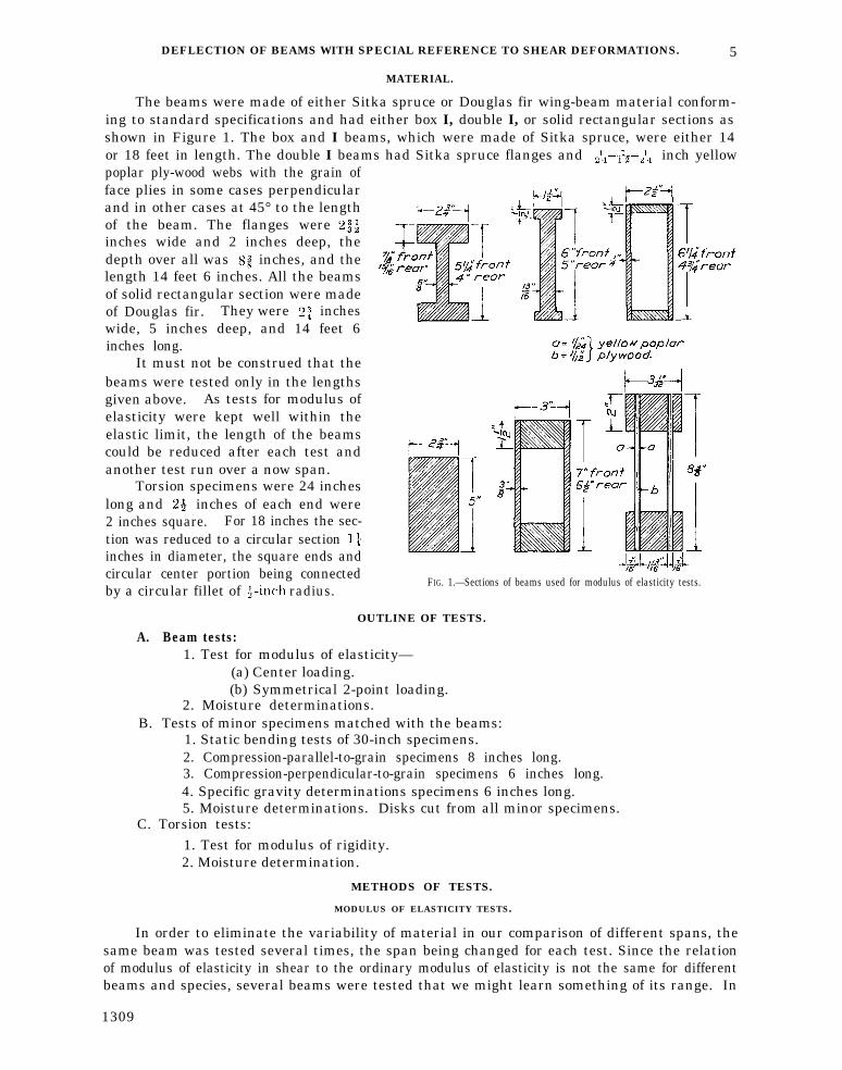
The beams were made of either Sitka spruce or Douglas fir wing-beam material conform-ing to standard specifications and had either box I, double I, or solid rectangular sections asshown in Figure 1. The box and I beams, which were made of Sitka spruce, were either 14or 18 feet in length. The double I beams had Sitka spruce flanges and inch yellowpoplar ply-wood webs with the grain offace plies in some cases perpendicularand in other cases at 45° to the lengthof the beam. The flanges wereinches wide and 2 inches deep, thedepth over all was inches, and thelength 14 feet 6 inches. All the beamsof solid rectangular section were madeof Douglas fir. They were incheswide, 5 inches deep, and 14 feet 6inches long.
It must not be construed that thebeams were tested only in the lengthsgiven above. As tests for modulus ofelasticity were kept well within theelastic limit, the length of the beamscould be reduced after each test andanother test run over a now span.
Torsion specimens were 24 incheslong and inches of each end were2 inches square. For 18 inches the sec-tion was reduced to a circular sectioninches in diameter, the square ends andcircular center portion being connectedby a circular fillet of radius.
FIG. 1.—Sections of beams used for modulus of elasticity tests.
OUTLINE OF TESTS.
A. Beam tests:1. Test for modulus of elasticity—
(a) Center loading.(b) Symmetrical 2-point loading.
2. Moisture determinations.B. Tests of minor specimens matched with the beams:
1. Static bending tests of 30-inch specimens.2. Compression-parallel-to-grain specimens 8 inches long.3. Compression-perpendicular-to-grain specimens 6 inches long.4. Specific gravity determinations specimens 6 inches long.5. Moisture determinations. Disks cut from all minor specimens.
C. Torsion tests:1. Test for modulus of rigidity.2. Moisture determination.
METHODS OF TESTS.
MODULUS OF ELASTICITY TESTS.
In order to eliminate the variability of material in our comparison of different spans, thesame beam was tested several times, the span being changed for each test. Since the relationof modulus of elasticity in shear to the ordinary modulus of elasticity is not the same for differentbeams and species, several beams were tested that we might learn something of its range. In
1309
6 REPORT NATIONAL ADVISORY COMMITTEE FOR AERONAUTICS
some cases the ends were cut off to maintain a constant overhang and in other cases the totallength was kept constant as the span was changed. The accompanying tables show how spansup to 18 were reduced by either 1 or 2 foot, intervals to either 2 or 3 foot spans. Deflectionswere read by referring a scale, attached at the center of the beam, to a fine wire drawn betweennails over the supports, or when greater precision was required, by observing the movement ofa pointer on a dial attached to a light beam resting on nails driven in the test beam over thesupports. A fine silk line attached to a nail at the center of the test beam passed around thedrum of the dial and carried a weight to keep it taut. Movements of the test beam were somultiplied that the pointer gave deflections to 0.0001 inch, whereas by the first method deflec-
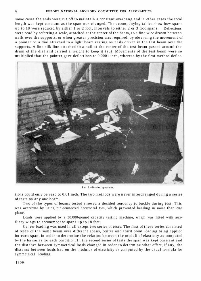
FIG. 2.—Torsion apparatus.
tions could only be read to 0.01 inch. The two methods were never interchanged during a seriesof tests on any one beam.
Two of the types of beams tested showed a decided tendency to buckle during test. Thiswas overcome by using pin-connected horizontal ties, which prevented bending in more than oneplane.
Loads were applied by a 30,000-pound capacity testing machine, which was fitted with aux-iliary wings to accommodate spans up to 18 feet.
Center loading was used in all except two series of tests. The first of these series consistedof test’s of the same beam over different spans, center and third point loading bring appliedfor each span, in order to determine the relation between the moduli of elasticity as computedby the formulas for each condition. In the second series of tests the span was kept constant andthe distance between symmetrical loads changed in order to determine what effect, if any, thedistance between loads had on the modulus of elasticity as computed by the usual formula forsymmetrical loading.
1309

DEFLECTION OF BEAMS WITH SPECIAL REFERENCE TO SHEAR DEFORMATIONS. 7
There were matched with all I and box beams, static bending specimens approximately2 by 2 inches in section and 30 inches long, compression parallel test pieces 2 by 2 inches by 8inches long, and compression perpendicular specimens 2 by 2 inches by 6 inches long. Theseminors were tested and specific gravity and moisture determinations made in accordance withstandard laboratory methods.
A simple torsion apparatus was set up in an ordinary wood lathe. Figure 2 is a photographof the machine. Load was applied in 25 inch-pound increments and the angle of twist read foreach increment over a 16-inch gauge length. All torsion specimens were matched with stand-ard 2 by 2 inch specimens which were tested in bending over a 28-inch span. For furtherdescription of the test see Description of figures and tables.
DESCRIPTION OF FIGURES AND TABLES.
Figure 1.—This figure shows sections of all beams used in modulus of elasticity testsSuch dimensions as “7 inches front” and “ inches rear” indicate that two beams of that typewere tested, the words front and rear designating their position in the wing.
Figure 2.—This is a photograph of a simple torsion apparatus set up in an ordinary woodlathe. The right-hand wooden disk is set on ball bearings and has a wire passing around it toa tray marked “load.” The smaller wooden disk at the left is fixed. The specimen is square atthe ends, which fit into the two wooden disks. The angle of twist was measured by the twotroptometer arms, each of which carries a string which passes around the drum of a dial.
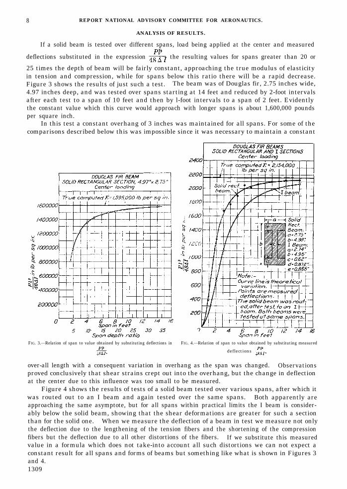
Figure 3—This shows the typical variation of the quantity with span for a beam of
solid rectangular section loaded at the center.Figure 4.—This shows a similar variation before and after routing a solid section. The
amount of shear deformation is considerably increased by reducing the thickness at the planeof maximum horizontal shear.
Figure 5.—This figure shows the same variation. The values, which are the average
from tests of three beams, are expressed as per cent of the true modulus of elasticity in tensionand compression.
Figure 6.—Curve A shows the distribution of shear stress in a beam of rectangular section,and curve B the distribution in an I beam with square corners which was used as a basis for thedevelopments of the shear deformation formulas presented in this report.
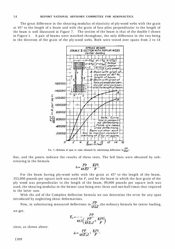
Figure 7.—This figure shows the superiority of 45° ply wood as regards rigidity. Shear dis-
tortion being loss the values of are closer to the true modulus of elasticity for the beam with
45° ply wood.
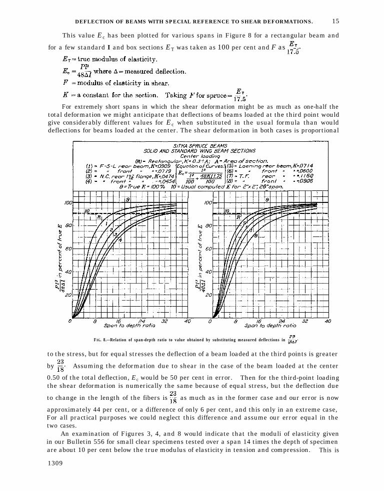
Figure 8—In this dual figure is represented the variation of with span for various
standard wing-beam sections as well as for a solid section. The beams were all made of
Sitka spruce and tested under center loading. The values of are expressed as per cent
of the true modulus of elasticity in tension and compression. The dimensions of these beamsare shown in Figure 1. In the upper row, from left to right, is the F-5-L, Loening, and TF,and in the center of the lower row, the NC.
Table I.—In this table is given the measured and computed deflections of Douglas-firbeams of solid rectangular section loaded at the center. The formula used takes into accountshear deformations usually neglected in such calculations. The differences in the two valuesare expressed as errors in per cent of the measured deflection.
Table II.—Here we have measured and computed deflections for standard sections. Fordescription of these sections see description of Figure 8. The computed deflections arcfrom two formulas, one taking shear into account and the other neglecting it. Errors areexpressed in per cent of the measured deflections.
1309
8 REPORT NATIONAL ADVISORY COMMITTEE FOR AERONAUTICS.
ANALYSIS OF RESULTS.
If a solid beam is tested over different spans, load being applied at the center and measured
deflections substituted in the expression the resulting values for spans greater than 20 or
25 times the depth of beam will be fairly constant, approaching the true modulus of elasticityin tension and compression, while for spans below this ratio there will be a rapid decrease.Figure 3 shows the results of just such a test. The beam was of Douglas fir, 2.75 inches wide,4.97 inches deep, and was tested over spans starting at 14 feet and reduced by 2-foot intervalsafter each test to a span of 10 feet and then by l-foot intervals to a span of 2 feet. Evidentlythe constant value which this curve would approach with longer spans is about 1,600,000 poundsper square inch.
In this test a constant overhang of 3 inches was maintained for all spans. For some of thecomparisons described below this was impossible since it was necessary to maintain a constant
FIG. 3.—Relation of span to value obtained by substituting deflections in FIG. 4.—Relation of span to value obtained by substituting measured
deflections
over-all length with a consequent variation in overhang as the span was changed. Observationsproved conclusively that shear strains crept out into the overhang, but the change in deflectionat the center due to this influence was too small to be measured.
Figure 4 shows the results of tests of a solid beam tested over various spans, after which itwas routed out to an I beam and again tested over the same spans. Both apparently areapproaching the same asymptote, but for all spans within practical limits the I beam is consider-ably below the solid beam, showing that the shear deformations are greater for such a sectionthan for the solid one. When we measure the deflection of a beam in test we measure not onlythe deflection due to the lengthening of the tension fibers and the shortening of the compressionfibers but the deflection due to all other distortions of the fibers. If we substitute this measuredvalue in a formula which does not take-into account all such distortions we can not expect aconstant result for all spans and forms of beams but something like what is shown in Figures 3and 4.1309

DEFLECTION OF BEAMS WITH SPECIAL REFERENCE TO SHEAR DEFORMATIONS. 9
While it is recognized that any distortion due to a force producing bending moment isreflected in the deflection of a beam, the only distortions that appear to be of a magnitude tojustify consideration are those resulting from the lengthening of the tension fibers and shorteningof the compression fibers and from shear stresses.
The asymptote or constant value which these curves of Figures 3 and 4 approach is the truemodulus of elasticity in tension and compression, which we will call ET . If we assume that the
FIG. 5.—Relational span-depth ratio to value obtained by substi-tuting measured deflections in
deformation due to shear is proportional to the moment, a point which will be proved later,we may write
where,= the deflection of a beam of span l1 loaded at the center with a load P1, and
= the modulus of elasticity in shear.
For a span l2 with a load P2 at the center of the same beam we have
These two equations contain the two unknown quantities ET and F, and hence the solutionof the two equations will furnish values of the true modulus ET and the shearing modulus F.By making many experiments on the same beam instead of two and writing an equation foreach it is possible to obtain reliable values for these two moduli for that particular beam. Fromthe results shown in Figure 3 the true modulus of elasticity was found in this way to be 1,595,000pounds per square inch and from the results shown in Figure 4 it was found to be 2,154,000pounds per square inch. Figure 5 shows results similar to those of Figures 3 and 4. They areexpressed, however, in per cent of the true computed ET taken as 100 per cent. In this case eachpoint represents the average of three beams rather than the results of a single beam.
Since for ordinary spans the deformation due to shear is small in comparison with thedeflection due to elongation and compression of the fibers, it was difficult to obtain reliable values
64938–24—2
1309
10 REPORT NATIONAL ADVISORY COMMITTEE FOR AERONAUTICS.
for F by the solution of simultaneous equations as outlined above, since the slightest errors inmeasuring deflections for ordinary spans were reflected in F more than in ET . Torsion testswere made for the purpose of checking on this value, which showed F for spruce to be about1/15 ET and for Douglas fir about 1/17 or 1/18 ET .
Assuming a parabolic distribution of shear stress, as shown in Figure 6, expressions forshear deformation can be determined by setting up an expression for internal work and equatingit to the external work done in producing shear distortions.
In this way, for a beam of solid rectangular section loaded at the center, we get:
and for an I or box beam with square corners similarly loaded:
which may be written
where,
The development of the above expressions is given in the appendix, together with expres-sions for other conditions of loading.
The above formula assumes the parabolic distribution of shear stress on a cross section of abeam, and the deflection due to shear is determined by the ordinary method of equating externalwork to internal energy. It involves high powers and numerous factors which may lead toinaccuracies when the ordinary approximations in calculations are employed. Consequently amore simple formula was sought.
The development of the second, a more simple formula, follows. In the two formulasthe same shear distribution is assumed, but in the second formula the fundamental assumptionis that deflections due to shear in any two beams of the same length, height, and moment ofinertia, which are similarly loaded, are proportional to the summations of the shear stresseson their respective vertical sections.
Let us assume that we have an I beam of a given length, depth, and moment of inertia, anda rectangular beam of the same length, depth, and of a width to make its moment of inertiaequal to that of the I beam. The shear stress distribution would be as indicated in Figure 6.Let us further assume that the shear deformations will be proportional to the areas under the
stress curve. Knowing the shear deflection of the rectangular beam to be when supported
at the ends and loaded at the center, we can determine f for an I beam similarly loaded by
1309

DEFLECTION OF BEAMS WITH SPECIAL REFERENCE TO SHEAR DEFORMATIONS. 11
multiplying this value by the ratio of the area under the shear stress curve of the I beam to thearea under the stress curve of the rectangle, which ratio is:
Referring to curve B, Figure 6
and since ABF is a parabola the area
the total area
and the total area
The area under the stress curve of the rectangular beam from the extreme fiber down to
the neutral axis, must necessarily
By our assumption the V’s and I’s will cancel and the deflection of the I beam will be:
where,Ar = area of rectangle. This value is readily expressed in dimensions of the I beam for, since
I of I beam = I of rectangle = 2/3 b K23,
and
which may be written
The formula can be applied to I and box sections of irregular shape by first
reducing the given section to one of equivalent section, which is one whose height equals themean height of the beam and whose flange areas equal those of the beam. By using K for theequivalent beam only a slight error will be introduced in the results.
1309

12 REPORT NATIONAL ADVISORY COMMITTEE FOR AERONAUTICS.
TABLE I.—Showing deflections determined by test compared with values computed by the formula.
Let us now see how measured deflections compared with those computed by the formulas.Table I shows the results of tests on five rectangular Douglas-fir beams approximately by 5inches in section. True moduli of elasticity in bending were computed as outlined in thisanalysis and the average found to be 1,918,000 pounds per square inch. The modulus of elas-ticity in shear F was taken as one-fifteenth of this value, or 127,900 pounds per square inch.The beams were supported near the ends and loaded at the center. Computed deflections wereobtained by substituting in the formula
where A = area of the cross section.The errors are expressed in percentage of the measured deflections. The average F was
used for all beams, but in using E its value for each particular beam was substituted. Anexamination of the table shows that test and computed values agree remarkably well.
In Table II are given measured deflections for the I and box beams, sections of which areshown in Figure 1.
Deflections were computed by the usual formula
and by the more exact formula
where,
K is the quantity
The true modulus of elasticity in tension and compression was used in both formulas. Theshearing modulus F was taken as 99,000 pounds per square inch, or about one-eighteenth theaverage true modulus of elasticity. Errors by the two formulas are expressed in per cent ofthe measured deflections. An examination of the table will show at a glance how much moreclosely the deflections can be estimated by the exact formula. For example, estimated valuesfor a 3-foot span by the exact formula check test results within 0 to 12.1 per cent, whereasvalues by the ordinary formula are in error from 34.6 to 65.7 per cent.
1309

14 REPORT NATIONAL ADVISORY COMMITTEE FOR AERONAUTICS.
The great difference in the shearing modulus of elasticity of ply-wood webs with the grainat 45° to the length of a beam and with the grain of face plies perpendicular to the length ofthe beam is well illustrated in Figure 7. The section of the beam is that of the double I shownin Figure 1. A pair of beams were matched throughout, the only difference in the two beingin the direction of the grain of the ply-wood webs. Both were tested over spans from 2 to 14
FIG. 7.—Relation of span to value obtained by substituting deflections in
feet, and the points indicate the results of these tests. The full lines were obtained by sub-stituting in the formula
For the beam having ply-wood webs with the grain at 45° to the length of the beam,353,000 pounds per square inch was used for F, and for the beam in which the face grain of theply wood was perpendicular to the length of the beam, 99,000 pounds per square inch wasused, the shearing modulus in the former case being over three and one-half times that requiredin the latter case.
With the aid of the Complete deflection formula we can determine the error for any spanintroduced by neglecting shear deformations.
Now, in substituting measured deflections in the ordinary formula for center loading,
we get:
since, as shown above:
1309
DEFLECTION OF BEAMS WITH SPECIAL REFERENCE TO SHEAR DEFORMATIONS. 15
This value Ec has been plotted for various spans in Figure 8 for a rectangular beam and
for a few standard I and box sections ET was taken as 100 per cent and F as
For extremely short spans in which the shear deformation might be as much as one-half thetotal deformation we might anticipate that deflections of beams loaded at the third point wouldgive considerably different values for Ec when substituted in the usual formula than woulddeflections for beams loaded at the center. The shear deformation in both cases is proportional
FIG. 8.—Relation of span-depth ratio to value obtained by substituting measured deflections in
to the stress, but for equal stresses the deflection of a beam loaded at the third points is greater
by Assuming the deformation due to shear in the case of the beam loaded at the center
0.50 of the total deflection, Ec would be 50 per cent in error. Then for the third-point loadingthe shear deformation is numerically the same because of equal stress, but the deflection due
to change in the length of the fibers is as much as in the former case and our error is now
approximately 44 per cent, or a difference of only 6 per cent, and this only in an extreme case,For all practical purposes we could neglect this difference and assume our error equal in thetwo cases.
An examination of Figures 3, 4, and 8 would indicate that the moduli of elasticity givenin our Bulletin 556 for small clear specimens tested over a span 14 times the depth of specimenare about 10 per cent below the true modulus of elasticity in tension and compression. This is
1309
16 REPORT NATIONAL ADVISORY COMMITTEE FOR AERONAUTICS.
true; it is a value obtained by substituting measured deflections in the usual deflection formulaneglecting shear deformation. However, if this value is in turn used to estimate the deflectionof a solid rectangular beam by substituting in the usual formula we arrive at the correct deflec-tion provided our span is 14 times the depth. For ordinary spans, say from 12 to 28 timesthe depth, the error would be within 5 per cent. For rectangular beams used in ordinary lengthsthen we would not vitiate our results to any great extent by using these values of modulus ofelasticity in the usual formula.
In the design of box and I sections with relatively little material at the plane of maximumhorizontal shear, however, very considerable errors will occur even for large span-depth ratiosunless the more accurate method of determining the elastic properties of a beam is employed.For some sections tested the error introduced at a span of 14 times the depth was over 35 percent as against 10 per cent for a solid rectangular beam.
CONCLUSIONS.
Because of the magnitude of shear distortions it is often necessary to calculate the elasticproperties of wood beams by formulas which take into account such distortions. This isespecially true for box and I beams which have the material distributed in a way to take careof maximum tensile and compressive stresses, which means a minimum of material at the planeof maximum longitudinal shear. The shear deformation is proportional to the moment to
which the beam is subjected and may be expressed by where P is the load on a beam of
span l, F is the modulus of elasticity in shear, and K a coefficient depending upon the shape ofthe cross section and upon the loading. Two formulas for the determination of K have beendeveloped. The first is a rather long formula developed by ordinary methods, the second asimpler formula and more empirical in its nature. Both check experimental results very closely,but the second formula is recommended because its use involves less labor and offers less oppor-tunity for error.
Usually shear deflections are neglected, and deflection determined by test when substitutedin the usual deflection formulas will give a modulus of elasticity less than the tension and com-pression modulus, the error increasing as the span is reduced. The elastic properties given insuch tables as are included in Bulletin 556 were determined in this way. These standardbending specimens have a span depth ratio of 14, for which ratio the modulus of elasticity inshear is about 10 per cent below the true modulus in tension and compression.
However, if these values are used in design they will give correct deflections for solid rec-tangular beams of the same span-depth ratio if substituted in the usual formulas with whichthey were determined. Furthermore, for ordinary spans, say from 12 to 28 times the depth ofbeam, they will give values correct within 5 per cent. For shorter spans it would be preferable touse the more exact formulas which take into account shear deformations. There is very littledifference in the errors for center and third-point loading. For beams of I and box section sheardistortions are far more pronounced and errors of considerable magnitude will be introducedeven for large span-depth ratios unless the exact formulas are employed.
Box beams with ply-wood webs have a greater modulus of rigidity with the grain of theplywood at 45° to the length of the beam than with the grain of the face plies perpendicular tothe length. Tests showed the former type to have a modulus of rigidity over three and one-halftimes the latter type.
1309
DEFLECTION OF BEAMS WITH SPECIAL REFERENCE TO SHEAR DEFORMATIONS. 17
APPENDIX.
The development of the formulas for shear deformations.
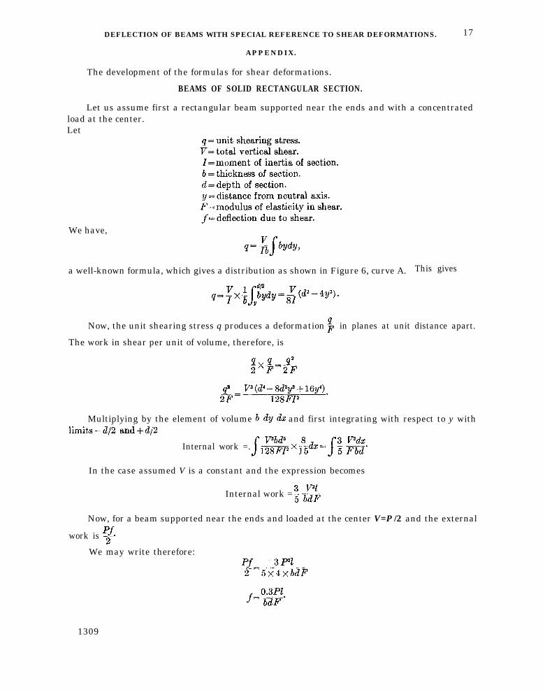
BEAMS OF SOLID RECTANGULAR SECTION.
Let us assume first a rectangular beam supported near the ends and with a concentratedload at the center.Let
We have,
a well-known formula, which gives a distribution as shown in Figure 6, curve A. This gives
Now, the unit shearing stress q produces a deformation in planes at unit distance apart.
The work in shear per unit of volume, therefore, is
Multiplying by the element of volume and first integrating with respect to y with
Internal work =.
In the case assumed V is a constant and the expression becomes
Internal work =
Now, for a beam supported near the ends and loaded at the center V=P /2 and the external
work is
We may write therefore:
1309

18 REPORT NATIONAL ADVISORY COMMITTEE FOR AERONAUTICS.
If ∆ = the total deflection we then have for a solid rectangular beam loaded at the center
In the case of a cantilever beam we would have and
for a solid rectangular beam. For beam supported at the ends and loaded equally at thethird points
where,
or
where,
P' = load at each third point,
P = total load.
Similarly, we may show that for a uniformly distributed load P
So far these expressions for shear deformations apply only to beams of rectangular section.
I OR BOX BEAMS.
Let us now examine an I beam or, what is practically the same, a box beam. The follow-ing notations will be used in addition to those already given:
In the flange:
In the web:
The distribution of shearing stress will be as shown in Figure 6, curve B.The internal work per unit volume is
where,
1309
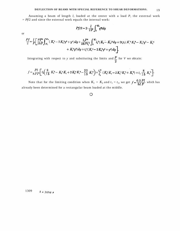
DEFLECTION OF BEAMS WITH SPECIAL REFERENCE TO SHEAR DEFORMATIONS. 19
Assuming a beam of length l, loaded at the center with a load P, the external work= Pf/2 and since the external work equals the internal work:
or
Integrating with respect to y and substituting the limits and for V we obtain:
Note that for the limiting condition when K1 = K2 and t1 = t2, we get which has
already been determined for a rectangular beam loaded at the middle.
1309