Embed Size (px)
Citation preview

Definition of PLR on the RS485-Bus
Definition of PLR on the RS485-bus
Version 1.06
Version 1.06 1/35

Definition of PLR on the RS485-Bus
Contents 1 INTRODUCTION .........................................................................................................................................4
1.1 MOTIVATION ............................................................................................................................................4 1.2 SCOPE OF THE DOCUMENT........................................................................................................................4 1.3 VALUES ....................................................................................................................................................4
2 ARCHITECTURAL OVERVIEW ..............................................................................................................5 2.1 BUS TOPOLOGY ........................................................................................................................................5 2.2 DATA FLOW..............................................................................................................................................5
3 HARDWARE REQUIREMENTS ...............................................................................................................6 3.1.1 RS485 Logical Signal Levels.............................................................................................................6
3.2 SUPPORTED SALMSON DEVICES ......................................................................................................................6 4 PROTOCOL ..................................................................................................................................................7
4.1 BYTE ORDERING AND FORMAT.................................................................................................................7 4.1.1 Supported Baud rates........................................................................................................................7
4.2 PACKET FIELDS ........................................................................................................................................7 4.2.1 Address field......................................................................................................................................7 4.2.2 Packet Type field ...............................................................................................................................7 4.2.3 Number field......................................................................................................................................7 4.2.4 Data Type field..................................................................................................................................8 4.2.5 Write-Point address field ..................................................................................................................8 4.2.6 Write-Point data field........................................................................................................................8 4.2.7 Read-Point address field ...................................................................................................................8 4.2.8 Read-Point data field ........................................................................................................................8 4.2.9 Checksum field ..................................................................................................................................8
4.3 PACKETS...................................................................................................................................................9 4.3.1 Request Packet ..................................................................................................................................9 4.3.2 Response Packet................................................................................................................................9
4.4 PROTOCOL TIMING .................................................................................................................................10 4.4.1 Byte Level........................................................................................................................................10 4.4.2 Packet Level ....................................................................................................................................10
4.5 PROTOCOL ERROR HANDLING ................................................................................................................10 4.5.1 Pump Communication Timeout.......................................................................................................11 4.5.2 Gateway Communication Timeout ..................................................................................................11
5 DEVICE PARAMETERS...........................................................................................................................12 5.1 WRITE-POINT PARAMETERS ...................................................................................................................12
5.1.1 Set value ..........................................................................................................................................12 5.1.2 Pump Command..............................................................................................................................13 5.1.3 Operation Mode ..............................................................................................................................13 5.1.4 Tmin for ∆p-T ....................................................................................................................................13 5.1.5 Tmax for ∆p-T....................................................................................................................................14 5.1.6 pmin for ∆p-T ....................................................................................................................................14 5.1.7 pmax for ∆p-T....................................................................................................................................14
5.2 READ-POINT PARAMETERS (SINGLE PUMP)............................................................................................15 5.2.1 Actual Differential Pressure............................................................................................................15 5.2.2 Flow Rate ........................................................................................................................................16 5.2.3 Power Consumption ........................................................................................................................16 5.2.4 Power Rating...................................................................................................................................16 5.2.5 Operation Hours .............................................................................................................................16 5.2.6 Mains Current .................................................................................................................................16 5.2.7 Speed ...............................................................................................................................................16 5.2.8 Medium Temperature ......................................................................................................................16 5.2.9 Current Operation Mode.................................................................................................................17 5.2.10 Pump Module ..................................................................................................................................17 5.2.11 Pump Type.......................................................................................................................................17 5.2.12 Max Speed .......................................................................................................................................19
2/35 Version 1.06

Definition of PLR on the RS485-Bus
5.2.13 Min Speed ....................................................................................................................................... 20 5.2.14 Max Pressure ∆p-c.......................................................................................................................... 20 5.2.15 Min Pressure ∆p-c .......................................................................................................................... 20 5.2.16 Max Pressure ∆p-v.......................................................................................................................... 20 5.2.17 Min Pressure ∆p-v .......................................................................................................................... 20 5.2.18 Max Flow Rate................................................................................................................................ 21 5.2.19 Min Flow Rate ................................................................................................................................ 21 5.2.20 Supported Errors ............................................................................................................................ 21 5.2.21 Supported Service Messages........................................................................................................... 21 5.2.22 Max Power Rating .......................................................................................................................... 21 5.2.23 Service Message.............................................................................................................................. 22 5.2.24 Error Type....................................................................................................................................... 22 5.2.25 Error Message ................................................................................................................................ 22 5.2.26 Pump Status .................................................................................................................................... 23 5.2.27 State Diagnostics ............................................................................................................................ 24
5.3 READ-POINT PARAMETERS (SPECIAL FOR A DOUBLE PUMP).................................................................. 24 5.3.1 Operating Hours DP....................................................................................................................... 25 5.3.2 Actual Differential Pressure (Slave) ............................................................................................... 25 5.3.3 Flow Rate (Slave)............................................................................................................................ 25 5.3.4 Power Consumption (Slave)............................................................................................................ 25 5.3.5 Power Rating (Slave) ...................................................................................................................... 25 5.3.6 Operating Hours (Slave)................................................................................................................. 25 5.3.7 Mains Current (Slave)..................................................................................................................... 26 5.3.8 Speed (Slave)................................................................................................................................... 26 5.3.9 Pump Module (Slave)...................................................................................................................... 26 5.3.10 Pump Type (Slave) .......................................................................................................................... 26 5.3.11 Error Type (Slave) .......................................................................................................................... 26 5.3.12 Pump Status (Slave) ........................................................................................................................ 26
6 PUMP SUPPORT........................................................................................................................................ 27 6.1 WRITE-POINT PARAMETERS................................................................................................................... 27
6.1.1 Pump Command.............................................................................................................................. 27 6.1.2 Operation Mode.............................................................................................................................. 27
6.2 READ-POINT PARAMETERS (SINGLE PUMP) ........................................................................................... 28 6.2.1 Pump Module.................................................................................................................................. 29 6.2.2 Service Message.............................................................................................................................. 29 6.2.3 Error Type....................................................................................................................................... 29 6.2.4 Error Message ................................................................................................................................ 30 6.2.5 Pump Status .................................................................................................................................... 30 6.2.6 State Diagnostics ............................................................................................................................ 31
6.3 READ-POINT PARAMETERS (SPECIAL FOR A DOUBLE PUMP).................................................................. 31 7 TRANSACTION EXAMPLES .................................................................................................................. 32
7.1 SINGLE PUMP ......................................................................................................................................... 32 7.1.1 Example 1: Simple Write ................................................................................................................ 32 7.1.2 Example 2: Simple Read ................................................................................................................. 32 7.1.3 A Read/Write example with unanswered data................................................................................. 33
7.2 DOUBLE PUMP........................................................................................................................................ 33 7.2.1 Example 4: Simple Read ................................................................................................................. 33
8 VERSION HISTORY ................................................................................................................................. 34
Version 1.06 3/35

Definition of PLR on the RS485-Bus
1 Introduction
1.1 Motivation In order to make configuration and operation easier, many building components support some way of remote controlling. This remote controlling does not only make it possible for the janitor to monitor devices and open gates or doors, letting the roller blinds down etc. But it also to makes automatic changes, as turning down the temperature at 6 p.m. or perhaps even when the last person has left.
In short: The communication between devices are becoming more and more common, and more and more different devices are connected to the main computer in order to allow what could be seen as an intelligent building.
This document describes the protocol that will enable a remote control of pumps and thus make it possible to incorporate them in the main building management system.
1.2 Scope of the Document This document describes the protocol and is targeted to developers that need to communicate with Salmson pumps.
In the second chapter, a brief device setup is shown and some fundamental knowledge is described.
In the third chapter the hardware requirements are briefly explained. This chapter is only included as assistance and is not to be thought of as a complete hardware specification.
The fourth chapter describes the protocol, how a packet as built, what order the bytes have, the meaning of the packets and the timing of packets and signals. It also explains the error handling in the protocol.
The fifth chapter describes all read and write parameters and their function.
The sixth chapter contains detailed communication examples to a pump.
1.3 Values All values in this document are decimal unless prefixed with “0x” for a hexadecimal value.
4/35 Version 1.06

Definition of PLR on the RS485-Bus
2 Architectural Overview
2.1 Bus Topology The main computer or BMS is called master since it effectively request information from the pumps. All Gateways (or in extension, the pumps) are slaves and they only passively responds to the requests from the master.
Pump 1-4 Pump 5-8
RS485 capable computer or PLC
24V
RS485
Figure 2.1, Example of a simple configuration
2.2 Data Flow The DigiCon (the gateway to the pumps) continually read data from all its pumps and acts as a provider of this data on the RS485-bus. Similarly it collects the data from all writes and gives it to the corresponding connected Pump.
The communication on the RS485-bus is always master initiated. After a request an answer or timeout must take place, it is not allowed to send another request without waiting for an answer or timeout. Timing is described at the end of chapter 4.
RS
485 capable com
puter or PLC
1. Request
2. Answer
3. Request
4. Timeout
5. Request
6. Answer
Figure 2.2, Example of the data flow
The data is requested and sent by the master. It is then received and responded to by a slave. A slave cannot by itself initiate a transfer.
Version 1.06 5/35
Definition of PLR on the RS485-Bus
3 Hardware Requirements The protocol described in this document is using the industry standard RS485 (for a specification see TIA/EIA-485). It is a two-wire bus protocol describing the physical and electrical levels of the wires. RS485 supports up to 32 connected transceivers (units) including the master, and allows a cable length up to 1000 meters.
Note: Make sure that the ends of the RS485 bus are correctly terminated by a 120 Ohm resistor (See DigiCon Manual for further information).
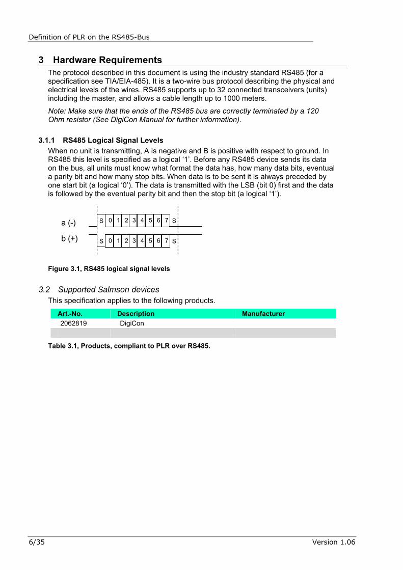
3.1.1 RS485 Logical Signal Levels When no unit is transmitting, A is negative and B is positive with respect to ground. In RS485 this level is specified as a logical ‘1’. Before any RS485 device sends its data on the bus, all units must know what format the data has, how many data bits, eventual a parity bit and how many stop bits. When data is to be sent it is always preceded by one start bit (a logical ‘0’). The data is transmitted with the LSB (bit 0) first and the data is followed by the eventual parity bit and then the stop bit (a logical ‘1’).
a (-)
b (+)
S 0 1 2 3 4 5 6 7 S
S 0 1 2 3 4 5 6 7 S
Figure 3.1, RS485 logical signal levels
3.2 Supported Salmson devices This specification applies to the following products.
Art.-No. Description Manufacturer 2062819 DigiCon
Table 3.1, Products, compliant to PLR over RS485.
6/35 Version 1.06

Definition of PLR on the RS485-Bus
4 Protocol
4.1 Byte Ordering and format In PLR, one byte is always transmitted with 1 start bit, 8 data bits and 1 stop bit. No parity is used in PLR. The data bits are sent LSB First and the bits are also numbered in this order, LSB = bit 0.
S 0 1 2 3 4 5 6 7 S Figure 4.1, one byte with start and stop bit
No handshake protocol is implemented and a whole packet can be sent without a pause. Usually there are no gaps within a packet.
Byte ordering is Low byte before High byte. For example: The Write-Point 44 with data type 32 and value 3000 (0x0BB8) is sent as 0x2C, 0x20, 0xB8, 0x0B.
4.1.1 Supported Baud rates The DigiCon supports the following baud rates: 1200, 2400, 4800, 9600, 19200, 38400, 57600, 76800 and 115200.
4.2 Packet Fields The packets consist of several different fields, and each field is defined as described below.
4.2.1 Address field The address field is always one byte and can contain the values 0 to 255. It contains the address of the slave that is addressed or the slave answering a request. The master always uses this field to direct the message to a specific slave. The slave always writes its own address in this field in order to tell the master from whom the answer came.
4.2.2 Packet Type field Every packet has a packet type and it describes the purpose of the packet. The packet type field has the size of one byte. It can have the values described in Table 4.1.
Packet Type Field
Description Issuer
0 Response Packet (see Chapter 4.3.2)
Slave only
3 Request Packet (see Chapter 4.3.1)
Master only
Table 4.1, Packet Types
4.2.3 Number field The number field contains the number of following elements. The elements following the number field must be of the same size. This specific size is dependent on where and in what packet type the number field is located. See section 4.3.1 and section 4.3.2.
Version 1.06 7/35

Definition of PLR on the RS485-Bus 4.2.4 Data Type field
When data is sent within a packet it is always accompanied with a data type. The data type has the size of one byte. It can have the values described in Table 4.2.
Data Type Field (Dec)
Description Example Value
Example value Seen on bus
1 1 byte value in low-byte 0xF3 0xF3, 0x00 2 1 byte value in high-byte 0xF3 0x00, 0xF3 3 2 byte value with resolution 1 10 0x0A, 0x00 32 2 byte value with resolution 0.1 10.0 0x64, 0x00 33 2 byte value with resolution 10 10 0x01, 0x00
Table 4.2, Data Types
Note: Data Types should not be used as the only source of formatting a parameter. For example: the Write-Point address 1 has the type 32, but the resolution is 0.5 (%).
4.2.5 Write-Point address field The Write-Point address is always one byte and it tells the slave what Write-Point data follows so that it can be written at the correct position in the slave’s memory.
4.2.6 Write-Point data field Write-Point data is always sent as four bytes. The first byte is the Write-Point address (see Table 5.1), the second is the Write-Point Data Type (see Table 4.2) and the third and fourth contains the value that is to be written. A Write-Point parameter can only be written, it is not possible to read a Write-Point value from a pump.
4.2.7 Read-Point address field The Read-Point address is always one byte and it tells the slave what Read-Point data that is requested, or in a response packet, it precedes the actual values of the Read-Points that the master has requested.
4.2.8 Read-Point data field Read-Point data is always sent as four bytes. The first byte is the Read-Point address (see Table 5.4 and Table 5.12), the second is the Read-Point Data Type (see Table 4.2) and the third and fourth contains the value that has been read from the slave. The Read-Point parameters can only be read from a pump.
4.2.9 Checksum field The checksum has the size of exactly one byte, and it is the simple addition of all bytes before the checksum, represented as an 8 bit unsigned value (overflow is discarded). Examples can be found in chapter 6.
Address Type Data Checksum
Figure 4.2, Checksum
8/35 Version 1.06

Definition of PLR on the RS485-Bus
4.3 Packets
4.3.1 Request Packet The Master always sends a request packet. In this packet both write and read requests can be sent together. It is allowed to set the number of writing or reading addresses to zero, if no data is to be written or read.
The first byte is the device address and the type of the packet (always 3 for a request packet). After these two bytes comes the number of write data points, followed by the data for the Write-Points. The Write-Point data is always sent as 4 bytes consisting of the Write-Point address, its type and the value to be written, the value is always 2 bytes long, even if only a one-byte value is to be transmitted. The number of Read-Point addresses, followed by the individual addresses that is to be read from the slave follows the Write-Point data. At the end of the packet the checksum is sent. It is the checksum for all bytes in the packet not including the checksum itself.
1 byte
address packet type Write-Point data Read-Point addresses checksum
Write-Point address data type data
(lowbyte) data
(highbyte)
N * 4 bytes
number N of Write-Points
number M of Read-Points
1 byte 1 byte 1 byte 1 byte M * 1 bytes 1 byte
Read-Point address
1 byte 1 byte 1 byte 1 byte
Figure 4.3, Request Packet
Note: The maximum allowed size in bytes of a request packet is 72 bytes. Also the number (M) of Read-Points is limited to a maximum of 28 in one packet.
4.3.2 Response Packet The Slave always responds with a response packet. In this packet only Read-Point data is sent. It is allowed to set the number of Read-Point data to zero, if no data can be read.
The first byte is the device address (of the slave) and the type of the packet (always 0 for a response packet). After these two bytes comes the number (L) of Read-Point data followed by the data for the Read-Points. The Read-Point data is always sent as 4 bytes consisting of the Read-Point address, its type and the value to be written, the value is always 2 bytes long, even if only a one-byte value is to be transmitted. At the end of the packet the checksum is sent. It is the checksum for all bytes in the packet excluding the checksum itself.
Note: if no Read-Point is answered (empty packet) it could also mean that there is no pump connected or that the connected pump has a communication timeout (see section 4.5.1).
1 byte
address packet type Read-Point data checksum
Read-Point address data type data
(lowbyte) data
(highbyte)
L * 4 bytes
number L of Read-Points
1 byte 1 byte 1 byte 1 byte
1 byte 1 byte 1 byte
Figure 4.4, Response Packet
Note: The response buffer in the master must be able to hold at least 120 bytes.
Version 1.06 9/35
Definition of PLR on the RS485-Bus 4.4 Protocol Timing
In order to allow for a stable communication, the PLR protocol has several specified timing constraints.
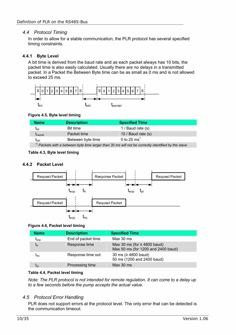
4.4.1 Byte Level A bit time is derived from the baud rate and as each packet always has 10 bits, the packet time is also easily calculated. Usually there are no delays in a transmitted packet. In a Packet the Between Byte time can be as small as 0 ms and is not allowed to exceed 25 ms.
S 0 1 2 3 4 5 6 7 S S 0 1 2 3 4 5 6 7 S
tbit tbbt tpacket
Figure 4.5, Byte level timing
Name Description Specified Time tbit Bit time 1 / Baud rate (s) tpacket Packet time 10 / Baud rate (s) tbbt Between byte time 0 to 25 ms1 1) Packets with a between byte time larger than 30 ms will not be correctly identified by the slave
Table 4.3, Byte level timing
4.4.2 Packet Level
Request Packet Response Packet Request Packet
teop
tpt
trt
Request Packet Request Packet
teop trto
teop
Figure 4.6, Packet level timing
Name Description Specified Time teop End of packet time Max 30 ms trt Response time Max 30 ms (for ≥ 4800 baud)
Max 50 ms (for 1200 and 2400 baud) trto Response time out 30 ms (≥ 4800 baud)
50 ms (1200 and 2400 baud) tpt Processing time Max 30 ms
Table 4.4, Packet level timing
Note: The PLR protocol is not intended for remote regulation. It can come to a delay up to a few seconds before the pump accepts the actual value.
4.5 Protocol Error Handling PLR does not support errors at the protocol level. The only error that can be detected is the communication timeout.
10/35 Version 1.06

Definition of PLR on the RS485-Bus
4.5.1 Pump Communication Timeout The DigiCon buffers the last value from the pump up to a minute after it has stopped transmitting. After this minute no data is returned on requests and the “empty packet” is sent. This empty packet consists of the address of the slave, the response packet type (always 0) and zero Read-Points (always 0). It thus ends with a checksum equal to the address of the slave (the packet is always sent as “X00X“, where the “X” stands for the actual address of the slave). In order to assure that an accidental reset of the DigiCon or the pump, does not trigger the communication timeout, it is suggested to wait one minute after receiving the first “empty packet”. If still no data is returned within this minute the master should issue a pump communication timeout for that specified pump.
4.5.2 Gateway Communication Timeout If the Gateway is powered off it does not answer any requests for all its connected pumps, even if the pumps are still running. This must be detected by the master and the master should issue a Gateway communication timeout if no requests has been answered within a minute after the first unanswered request. A request does not count as unanswered when an “empty packet” is received.
Version 1.06 11/35
Definition of PLR on the RS485-Bus
5 Device Parameters The Device Parameter space is split in two parts, the Write-Point parameters and the Read-Point parameters.
Note: The Write-Point parameter with address 1 is thus not the same as the Read-Point parameter with address 1. They even have different Units.
5.1 Write-Point Parameters Write-Point address
Description Data Type Unit
1 Set Value 32 0.5% 40 Pump Command 1 See Table 5.2 42 Operation Mode 1 See Table 5.3 44 Tmin for ∆p-T 32 0.1 K 45 Tmax for ∆p-T 32 0.1 K 46 pmin for ∆p-T 32 0.1 m WS1 47 pmax for ∆p-T 32 0.1 m WS1 1) 1 m WS ≈ 9.8 kPa = 0.098 bar
Table 5.1, Write-Point addresses
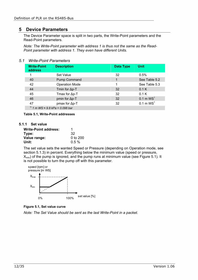
5.1.1 Set value Write-Point address: 1 Type: 32 Value range: 0 to 200 Unit: 0.5 %
The set value sets the wanted Speed or Pressure (depending on Operation mode, see section 5.1.3) in percent. Everything below the minimum value (speed or pressure, Xmin) of the pump is ignored, and the pump runs at minimum value (see Figure 5.1). It is not possible to turn the pump off with this parameter.
set value [%]
speed [rpm] or pressure [m WS]
Xmax
Xmin
0% 100%
Figure 5.1, Set value curve
Note: The Set Value should be sent as the last Write-Point in a packet.
12/35 Version 1.06
Definition of PLR on the RS485-Bus
5.1.2 Pump Command Write-Point address: 40 Type: 1 Value range: 0 to 0xFF Unit: see Table 5.2
This Write-Point controls the on, off, max speed and min speed modes of the pump.
Note: “max speed“ has priority over “min speed” and “on/off”, and “min speed“ has priority over “on/off”.
Bit number Bit = 1 Bit = 0 Note 0 Pump on Pump off Bit number 1 and 2
has priority 1 Min Speed1 Normal operation Bit number 2 has
priority 2 Max Speed Normal operation 3 Reserved Not allowed Must always be ‘1’ All other bits must be set to ‘0’ 1) The actual speed in the Min Speed mode can differ slightly from the “min speed” Read-Point, it depends on what pump is connected and if it has a special value specified.
Table 5.2, Pump Command bit set
5.1.3 Operation Mode Write-Point address: 42 Type: 1 Value range: 0-6 Unit: see Table 5.3
This Write-Point controls the operation mode of the pump. If a specified pump does not support the current selected mode it goes in mode 3 (∆p-c). The current operation mode can be read back by the Read-Point 11 (see section 5.2.9).
Value Operation mode 0 Unknown 1 Fixed speed 2 Reserved 3 ∆p-c regulation 4 ∆p-v regulation 5 Reserved 6 ∆p-T regulation All other values are reserved and should not be used
Table 5.3, Operation Mode value
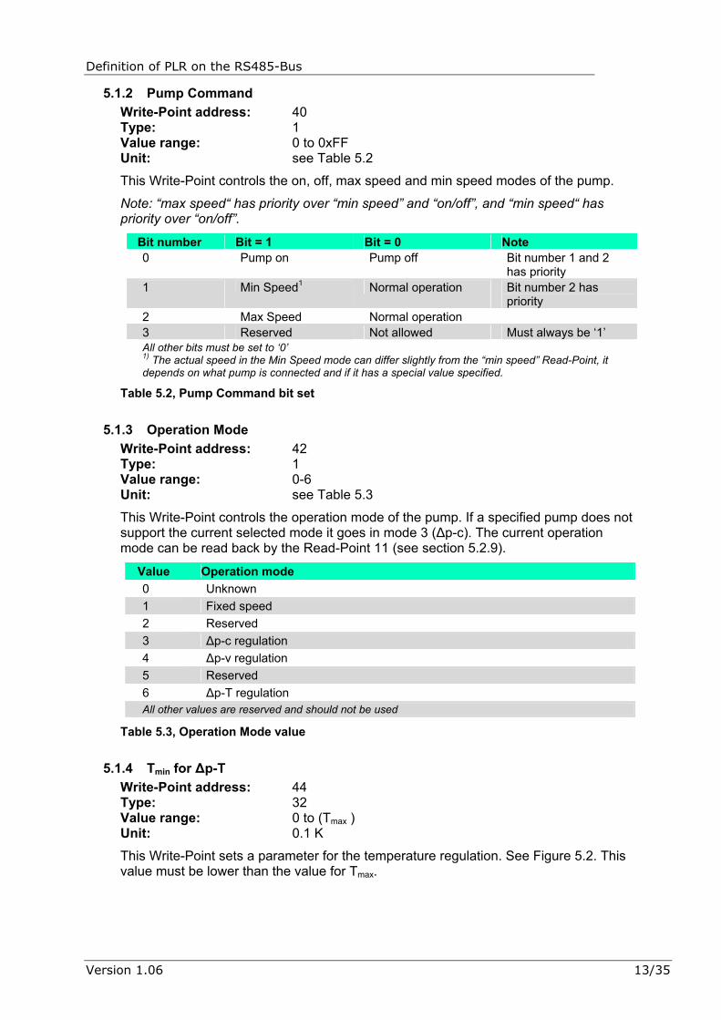
5.1.4 Tmin for ∆p-T Write-Point address: 44 Type: 32 Value range: 0 to (Tmax ) Unit: 0.1 K
This Write-Point sets a parameter for the temperature regulation. See Figure 5.2. This value must be lower than the value for Tmax.
Version 1.06 13/35
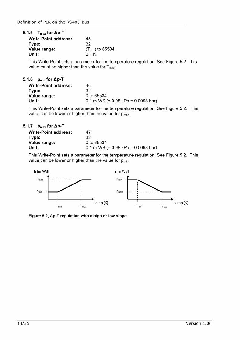
Definition of PLR on the RS485-Bus 5.1.5 Tmax for ∆p-T
Write-Point address: 45 Type: 32 Value range: (Tmin) to 65534 Unit: 0.1 K
This Write-Point sets a parameter for the temperature regulation. See Figure 5.2. This value must be higher than the value for Tmin.
5.1.6 pmin for ∆p-T Write-Point address: 46 Type: 32 Value range: 0 to 65534 Unit: 0.1 m WS (≈ 0.98 kPa = 0.0098 bar)
This Write-Point sets a parameter for the temperature regulation. See Figure 5.2. This value can be lower or higher than the value for pmax.
5.1.7 pmax for ∆p-T Write-Point address: 47 Type: 32 Value range: 0 to 65534 Unit: 0.1 m WS (≈ 0.98 kPa = 0.0098 bar)
This Write-Point sets a parameter for the temperature regulation. See Figure 5.2. This value can be lower or higher than the value for pmin.
temp [K]
h [m WS]
pmax
pmin
Tmin Tmax temp [K]
h [m WS]
pmax
pmin
Tmin Tmax
Figure 5.2, ∆p-T regulation with a high or low slope
14/35 Version 1.06

Definition of PLR on the RS485-Bus
5.2 Read-Point Parameters (Single Pump) Some pumps do not support some parameters. This means that some parameters can be left unanswered. Also some parameters give a special value when this parameter is not supported.
Note: When a pump not supports a specific Read-Point parameter and leaves this parameter out of the response packet, the main control must be able to handle this and must not go into an unspecified state or crash.
Read-Point address
Description Data Type Unit
1 Actual Differential Pressure 32 0.1 m WS1 2 Flow Rate 32 0.1 m³/h 3 Power Consumption 3 1 kWh 4 Power Rating 3 1 W 5 Operation Hours 33 10 h 6 Mains Current 32 0.1 A 7 Speed 3 1 rpm 8 Medium Temperature 32 0.1 K 10 Current Operation Mode 1 See Table 5.3. 16 Pump Module 1 See Table 5.5. 17 Pump Type 1 See Table 5.6. 18 Max Speed 3 1 rpm 19 Min Speed 3 1 rpm 20 Max Pressure ∆p-c 32 0.1 m WS1 21 Min Pressure ∆p-c 32 0.1 m WS1 22 Max Pressure ∆p-v 32 0.1 m WS1 23 Min Pressure ∆p-v 32 0.1 m WS1 24 Max Flow Rate 32 0.1 m³/h 25 Min Flow Rate 32 0.1 m³/h 26 Supported Errors 3 See Table 5.9. 27 Supported Service Messages 3 See Table 5.7. 28 Max Power Rating 3 1 W 35 Service Message 3 See Table 5.7. 36 Error Type 3 See Table 5.8. 37 Error Message 3 See Table 5.9. 38 Pump Status 3 See Table 5.10. 39 State Diagnostics 3 See Table 5.11. 1) 1 m WS ≈ 9.8 kPa = 0.098 bar
Table 5.4, Read-Point addresses
5.2.1 Actual Differential Pressure Read-Point address: 1 Type: 32 Value range: 0 to 65535 Unit: 0.1 m WS (≈ 0.98 kPa = 0.0098 bar)
This Read-Point returns the actual differential pressure.
Version 1.06 15/35

Definition of PLR on the RS485-Bus 5.2.2 Flow Rate
Read-Point address: 2 Type: 32 Value range: 0 to 65535 Unit: 0.1 m³/h
This Read-Point returns the current flow rate.
Note: A pump that does not support this Read-Point sets the value to 9999 (decimal).
5.2.3 Power Consumption Read-Point address: 3 Type: 3 Value range: 0 to 65535 Unit: 1 kWh
This Read-Point returns the total power consumption in kWh.
5.2.4 Power Rating Read-Point address: 4 Type: 3 Value range: 0 to 65535 Unit: 1 W
This Read-Point returns the current power rating in Watts.
5.2.5 Operation Hours Read-Point address: 5 Type: 33 Value range: 0 to 65535 Unit: 10 h
This Read-Point returns the operation hours in steps of 10 hours.
5.2.6 Mains Current Read-Point address: 6 Type: 32 Value range: 0 to 65535 Unit: 0.1 A
This Read-Point returns the mains current in steps of 0.1 Amperes
5.2.7 Speed Read-Point address: 7 Type: 3 Value range: 0 to 65534 Unit: 1 rpm
This Read-Point returns the current speed in rpm.
5.2.8 Medium Temperature Read-Point address: 8 Type: 32 Value range: 0 to 65535 Unit: 0.1 K
16/35 Version 1.06

Definition of PLR on the RS485-Bus
This Read-Point returns the Temperature. This value is only supported if the pump has a temperature sensor (SXE and SIRIUX).
Note: When this value is not supported, the pump does usually not respond to this Read-Point.
5.2.9 Current Operation Mode Read-Point address: 10 Type: 1 Value range: 0 to 8 Unit: See Table 5.3.
This Read-Point returns the current operation mode.
5.2.10 Pump Module Read-Point address: 16 Type: 1 Value range: 0 to 255 Unit: see Table 5.5.
This Read-Point returns if the pump module is frequency converter regulated or not.
Bit number Bit = 1 Bit = 0 Note 0 Pump is regulated
with a frequency-converter
Pump is not regulated
All other bits are unspecified and can be either ‘0’ or ‘1’.
Table 5.5, Pump Module Info
5.2.11 Pump Type Read-Point address: 17 Type: 1 Value range: 0 to 255 Unit: see Table 5.6.
This Read-Point returns the pump type (see Table 5.6).
Version 1.06 17/35

Definition of PLR on the RS485-Bus
Table 5.6, Pump Types
18/35 Version 1.06

Definition of PLR on the RS485-Bus
Value Pump Type Value Pump Type
Table 5.6, Pump Types (continued)
5.2.12 Max Speed Read-Point address: 18 Type: 3 Value range: 0 to 65535 Unit: 1 rpm
Version 1.06 19/35

Definition of PLR on the RS485-Bus
This Read-Point returns the max possible speed of the pump. It is the speed that is set when operation mode is set to “fixed speed” and the set value is set to 100%.
5.2.13 Min Speed Read-Point address: 19 Type: 3 Value range: 0 to 65535 Unit: 1 rpm
This Read-Point returns the min possible speed. It is the speed that is set when the operation mode is set to “fixed speed” and the set value is below the corresponding percentage for min speed.
5.2.14 Max Pressure ∆p-c Read-Point address: 20 Type: 32 Value range: 0 to 65535 Unit: 0.1 m WS (≈ 0.98 kPa = 0.0098 bar)
This Read-Point returns the max possible pressure. It is the pressure that is set when operation mode is set to “∆p-c regulation” and the set value is set to 100%.
5.2.15 Min Pressure ∆p-c Read-Point address: 21 Type: 32 Value range: 0 to 65535 Unit: 0.1 m WS (≈ 0.98 kPa = 0.0098 bar)
This Read-Point returns the min possible pressure. It is the pressure that is set when the operation mode is set to “∆p-c regulation” and the set value is below the corresponding percentage for min pressure.
5.2.16 Max Pressure ∆p-v Read-Point address: 22 Type: 32 Value range: 0 to 65535 Unit: 0.1 m WS (≈ 0.98 kPa = 0.0098 bar)
This Read-Point returns the max possible pressure. It is the pressure that is set when operation mode is set to “∆p-v regulation” and the set value is set to 100%.
Note: pumps that does not support “∆p-v regulation” either sets the values to the same as the ∆p-c max value or does not respond with data on this Read-Point. This Read-Point should not be used to see if the pump supports ∆p-v regulation.
5.2.17 Min Pressure ∆p-v Read-Point address: 23 Type: 32 Value range: 0 to 65535 Unit: 0.1 m WS (≈ 0.98 kPa = 0.0098 bar)
This Read-Point returns the min possible pressure. It is the pressure that is set when the operation mode is set to “∆p-v regulation” and the set value is below the corresponding percentage for min pressure.
20/35 Version 1.06
Definition of PLR on the RS485-Bus
Note: pumps that does not support “∆p-v regulation” either sets the values to the same as the ∆p-c min value or does not respond with data on this Read-Point. This Read-Point should not be used to see if the pump supports ∆p-v regulation.
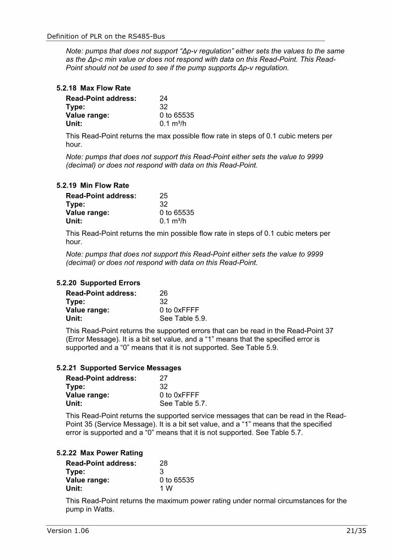
5.2.18 Max Flow Rate Read-Point address: 24 Type: 32 Value range: 0 to 65535 Unit: 0.1 m³/h
This Read-Point returns the max possible flow rate in steps of 0.1 cubic meters per hour.
Note: pumps that does not support this Read-Point either sets the value to 9999 (decimal) or does not respond with data on this Read-Point.
5.2.19 Min Flow Rate Read-Point address: 25 Type: 32 Value range: 0 to 65535 Unit: 0.1 m³/h
This Read-Point returns the min possible flow rate in steps of 0.1 cubic meters per hour.
Note: pumps that does not support this Read-Point either sets the value to 9999 (decimal) or does not respond with data on this Read-Point.
5.2.20 Supported Errors Read-Point address: 26 Type: 32 Value range: 0 to 0xFFFF Unit: See Table 5.9.
This Read-Point returns the supported errors that can be read in the Read-Point 37 (Error Message). It is a bit set value, and a “1” means that the specified error is supported and a “0” means that it is not supported. See Table 5.9.
5.2.21 Supported Service Messages Read-Point address: 27 Type: 32 Value range: 0 to 0xFFFF Unit: See Table 5.7.
This Read-Point returns the supported service messages that can be read in the Read-Point 35 (Service Message). It is a bit set value, and a “1” means that the specified error is supported and a “0” means that it is not supported. See Table 5.7.
5.2.22 Max Power Rating Read-Point address: 28 Type: 3 Value range: 0 to 65535 Unit: 1 W
This Read-Point returns the maximum power rating under normal circumstances for the pump in Watts.
Version 1.06 21/35

Definition of PLR on the RS485-Bus 5.2.23 Service Message
Read-Point address: 35 Type: 3 Value range: 0 to 0xFFFF Unit: See Table 5.7.
This Read-Point returns the actual service needed, see Table 5.7.
Bit number Bit = 1 Bit = 0 Note 0 Service needed1 No service needed 1 Exchange bearing1 No service needed 2 Oil bearing1 No service needed 3 Change sealing1 No service needed All other bits are unspecified and can be either ‘0’ or ‘1’. 1) In the case of a double pump, this applies to both master and slave.
Table 5.7, Service Message bit set
5.2.24 Error Type Read-Point address: 36 Type: 3 Value range: 0 to 0xFFFF Unit: see Table 5.8.
This Read-Point returns the pump error. If one bit is active an error is present. A possible list of errors is located in the pump manual.
Bit number Bit = 1 Bit = 0 Note 0 Module error No error 1 Motor error No error 2 Reserved Reserved 3 Pump error No error 4 Supply voltage error No error All other bits are unspecified and can be either ‘0’ or ‘1’.
Table 5.8, Error Type bit set
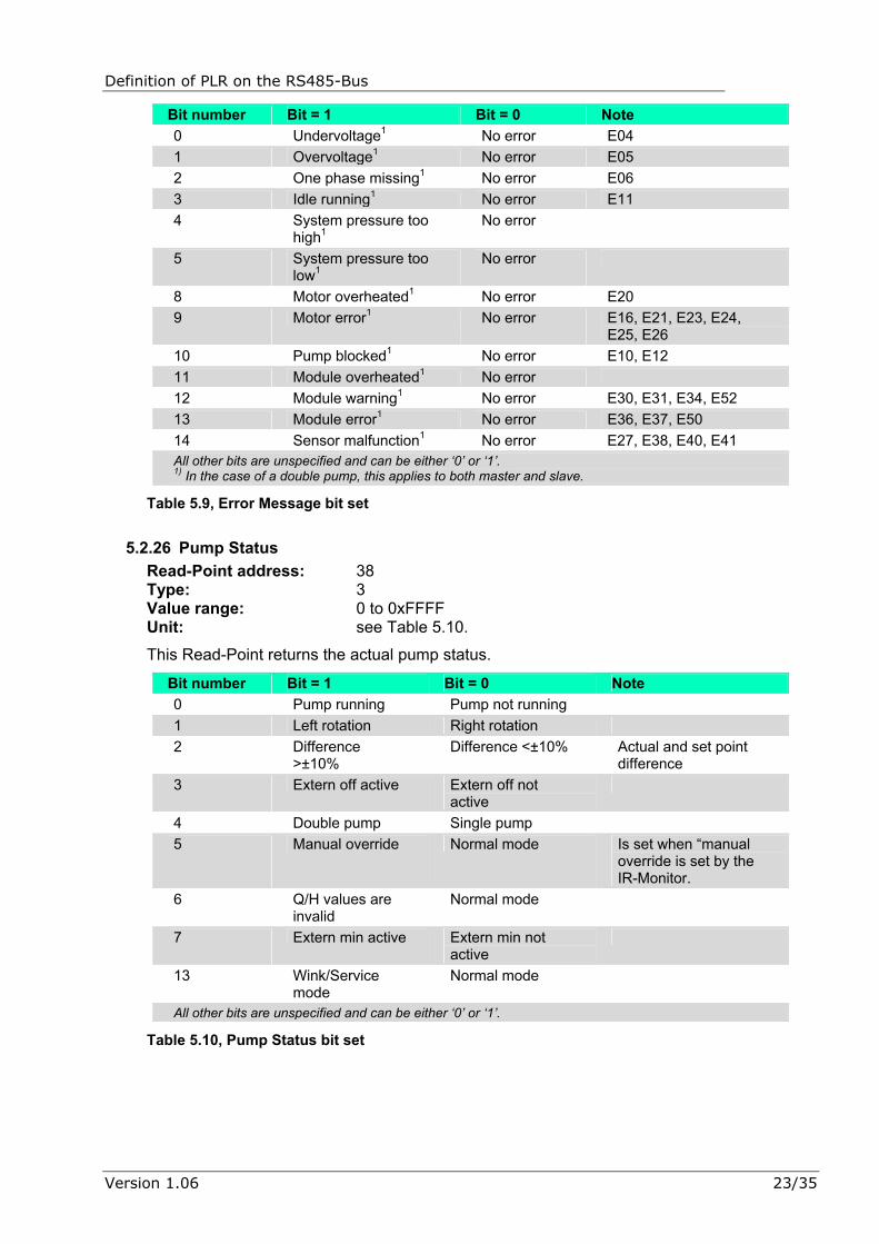
5.2.25 Error Message Read-Point address: 37 Type: 3 Value range: 0 to 0xFFFF Unit: See Table 5.9.
This Read-Point returns the error as specified in Table 5.9. No warnings are transmitted over the bus, only Errors (when the SSM relay becomes active in the Pump).
22/35 Version 1.06
Definition of PLR on the RS485-Bus
Bit number Bit = 1 Bit = 0 Note 0 Undervoltage1 No error E04 1 Overvoltage1 No error E05 2 One phase missing1 No error E06 3 Idle running1 No error E11 4 System pressure too
high1 No error
5 System pressure too low1
No error
8 Motor overheated1 No error E20 9 Motor error1 No error E16, E21, E23, E24,
E25, E26 10 Pump blocked1 No error E10, E12 11 Module overheated1 No error 12 Module warning1 No error E30, E31, E34, E52 13 Module error1 No error E36, E37, E50 14 Sensor malfunction1 No error E27, E38, E40, E41 All other bits are unspecified and can be either ‘0’ or ‘1’. 1) In the case of a double pump, this applies to both master and slave.
Table 5.9, Error Message bit set
5.2.26 Pump Status Read-Point address: 38 Type: 3 Value range: 0 to 0xFFFF Unit: see Table 5.10.
This Read-Point returns the actual pump status.
Bit number Bit = 1 Bit = 0 Note 0 Pump running Pump not running 1 Left rotation Right rotation 2 Difference
>±10% Difference <±10% Actual and set point
difference 3 Extern off active Extern off not
active
4 Double pump Single pump 5 Manual override Normal mode Is set when “manual
override is set by the IR-Monitor.
6 Q/H values are invalid
Normal mode
7 Extern min active Extern min not active
13 Wink/Service mode
Normal mode
All other bits are unspecified and can be either ‘0’ or ‘1’.
Table 5.10, Pump Status bit set
Version 1.06 23/35
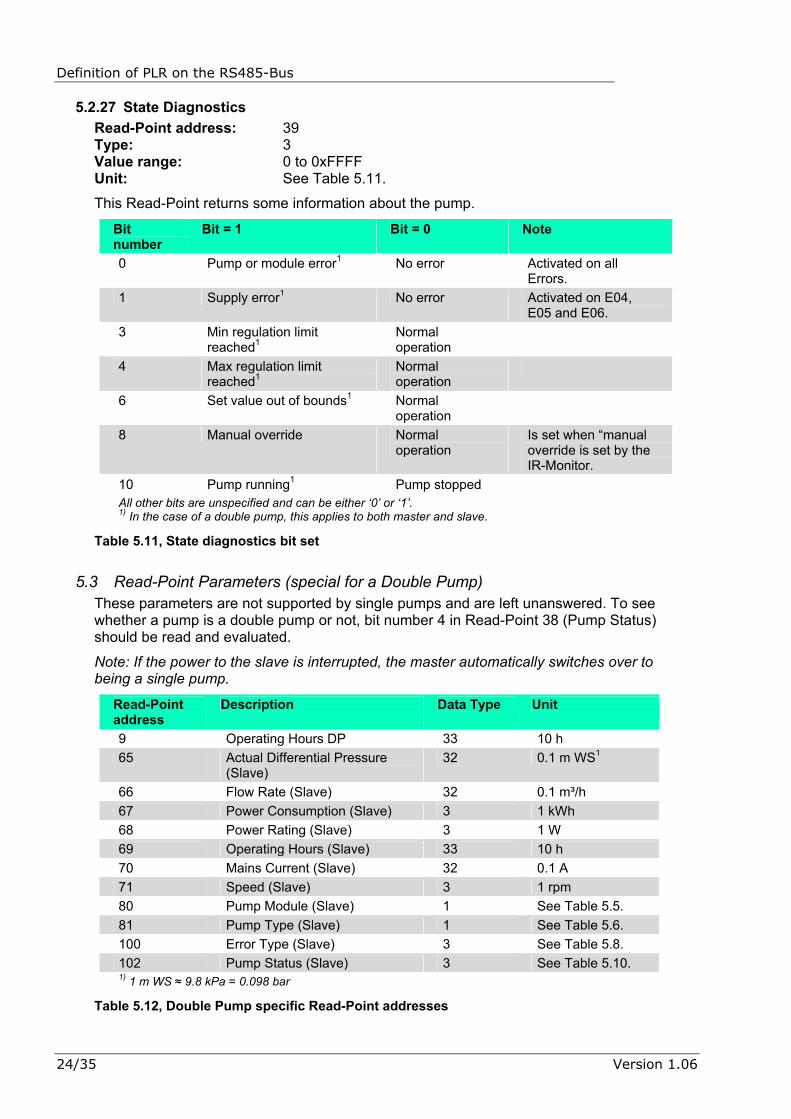
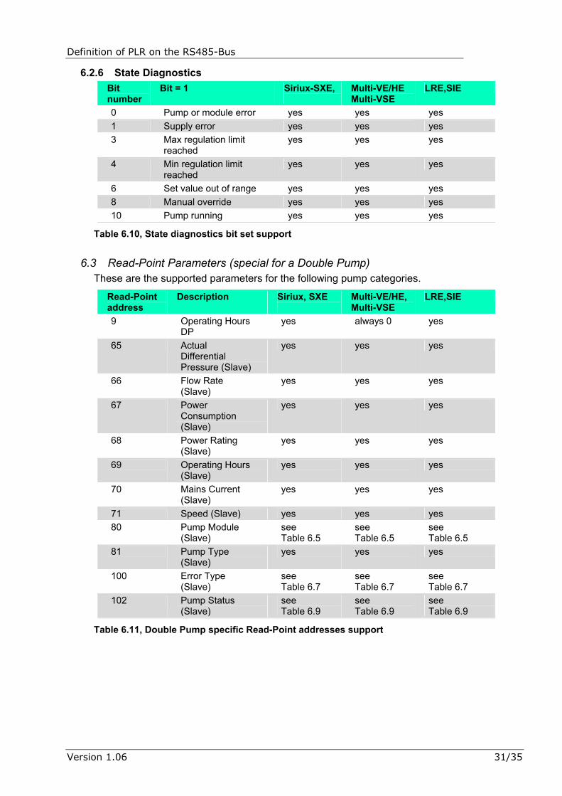
Definition of PLR on the RS485-Bus 5.2.27 State Diagnostics
Read-Point address: 39 Type: 3 Value range: 0 to 0xFFFF Unit: See Table 5.11.
This Read-Point returns some information about the pump.
Bit number
Bit = 1 Bit = 0 Note
0 Pump or module error1 No error Activated on all Errors.
1 Supply error1 No error Activated on E04, E05 and E06.
3 Min regulation limit reached1
Normal operation
4 Max regulation limit reached1
Normal operation
6 Set value out of bounds1 Normal operation
8 Manual override Normal operation
Is set when “manual override is set by the IR-Monitor.
10 Pump running1 Pump stopped All other bits are unspecified and can be either ‘0’ or ‘1’. 1) In the case of a double pump, this applies to both master and slave.
Table 5.11, State diagnostics bit set
5.3 Read-Point Parameters (special for a Double Pump) These parameters are not supported by single pumps and are left unanswered. To see whether a pump is a double pump or not, bit number 4 in Read-Point 38 (Pump Status) should be read and evaluated.
Note: If the power to the slave is interrupted, the master automatically switches over to being a single pump.
Read-Point address
Description Data Type Unit
9 Operating Hours DP 33 10 h 65 Actual Differential Pressure
(Slave) 32 0.1 m WS1
66 Flow Rate (Slave) 32 0.1 m³/h 67 Power Consumption (Slave) 3 1 kWh 68 Power Rating (Slave) 3 1 W 69 Operating Hours (Slave) 33 10 h 70 Mains Current (Slave) 32 0.1 A 71 Speed (Slave) 3 1 rpm 80 Pump Module (Slave) 1 See Table 5.5. 81 Pump Type (Slave) 1 See Table 5.6. 100 Error Type (Slave) 3 See Table 5.8. 102 Pump Status (Slave) 3 See Table 5.10. 1) 1 m WS ≈ 9.8 kPa = 0.098 bar
Table 5.12, Double Pump specific Read-Point addresses
24/35 Version 1.06

Definition of PLR on the RS485-Bus
5.3.1 Operating Hours DP Read-Point address: 9 Type: 32 Value range: 0 to 65534 Unit: 10 h
This Read-Point returns the operating hours of the double pump.
5.3.2 Actual Differential Pressure (Slave) Read-Point address: 65 Type: 32 Value range: 0 to 65534 Unit: 0.1 m WS (≈ 0.98 kPa = 0.0098 bar)
This Read-Point returns the actual differential pressure of the slave in a double pump.
5.3.3 Flow Rate (Slave) Read-Point address: 66 Type: 32 Value range: 0 to 65534 Unit: 0.1 m³/h
This Read-Point returns the actual flow rate of the slave in a double pump.
Note: A pump that does not support this Read-Point sets the value to 9999 (decimal).
5.3.4 Power Consumption (Slave) Read-Point address: 67 Type: 3 Value range: 0 to 65534 Unit: 1 kWh
This Read-Point returns the total power consumption in kWh of the Slave in a double pump.
5.3.5 Power Rating (Slave) Read-Point address: 68 Type: 3 Value range: 0 to 65534 Unit: 1 W
This Read-Point returns the current power rating of the Slave in a double pump.
5.3.6 Operating Hours (Slave) Read-Point address: 69 Type: 33 Value range: 0 to 65534 Unit: 10 h
This Read-Point returns the operation hours of the Slave in a double pump.
Version 1.06 25/35

Definition of PLR on the RS485-Bus 5.3.7 Mains Current (Slave)
Read-Point address: 70 Type: 32 Value range: 0 to 65534 Unit: 0.1 A
This Read-Point returns the mains current of the Slave in a double pump.
5.3.8 Speed (Slave) Read-Point address: 71 Type: 3 Value range: 0 to 65534 Unit: 1 rpm
This Read-Point returns the current speed of the Slave in a double pump.
5.3.9 Pump Module (Slave) Read-Point address: 80 Type: 1 Value range: 0 to 255 Unit: see Table 5.5.
This Read-Point returns the module type of the Slave in a double pump.
5.3.10 Pump Type (Slave) Read-Point address: 81 Type: 1 Value range: 0 to 255 Unit: see Table 5.6.
This Read-Point returns the pump type of the Slave in a double pump.
5.3.11 Error Type (Slave) Read-Point address: 100 Type: 3 Value range: 0 to 0xFFFF Unit: see Table 5.8.
This Read-Point returns the error of the Slave in a double pump.
5.3.12 Pump Status (Slave) Read-Point address: 102 Type: 3 Value range: 0 to 0xFFFF Unit: see Table 5.10.
This Read-Point returns the pump status of the Slave in a double pump.
26/35 Version 1.06

Definition of PLR on the RS485-Bus
6 Pump Support This chapter contains the supported parameters by Pump.
6.1 Write-Point Parameters These are the supported parameters for the following pump categories.
Write-Point address
Description Siriux, SXE Multi-HE/VE Multi-VSE
LRE, SIE
1 Set Value yes yes yes 40 Pump Command yes see
Table 6.2 see Table 6.2
42 Operation Mode yes see Table 6.3
see Table 6.3
44 Tmin for ∆p-T yes no 1) no 1) 45 Tmax for ∆p-T yes no 1) no 1) 46 pmin for ∆p-T yes no 1) no 1) 47 pmax for ∆p-T yes no 1) no 1) 1) Write-Point not supported by the pump, but the value can be written to the Modbus and read from the Modbus module.
Table 6.1, Write-Point pump support
6.1.1 Pump Command Bit number
Description Siriux, SXE
Multi-HE/VE Multi-VSE
LRE, SIE
0 Pump on/off yes yes yes 1 Min Speed yes yes yes 2 Max Speed yes yes yes 3 Reserved no no no
Table 6.2, Pump Command pump support
6.1.2 Operation Mode If the pump does not support the write value, the mode ∆p-c (p-c) regulation is automatically selected.
Value Operation mode Siriux, SXE Multi-VE/HE Multi-VSE
LRE, SIE
0 Unknown no no no 1 Fixed speed yes yes yes 2 Reserved no no no 3 ∆p-c regulation yes yes (p-c) yes 4 ∆p-v regulation yes no yes 5 Reserved no no no 6 ∆p-T regulation yes no no
Table 6.3, Operation Mode pump support
Version 1.06 27/35
Definition of PLR on the RS485-Bus
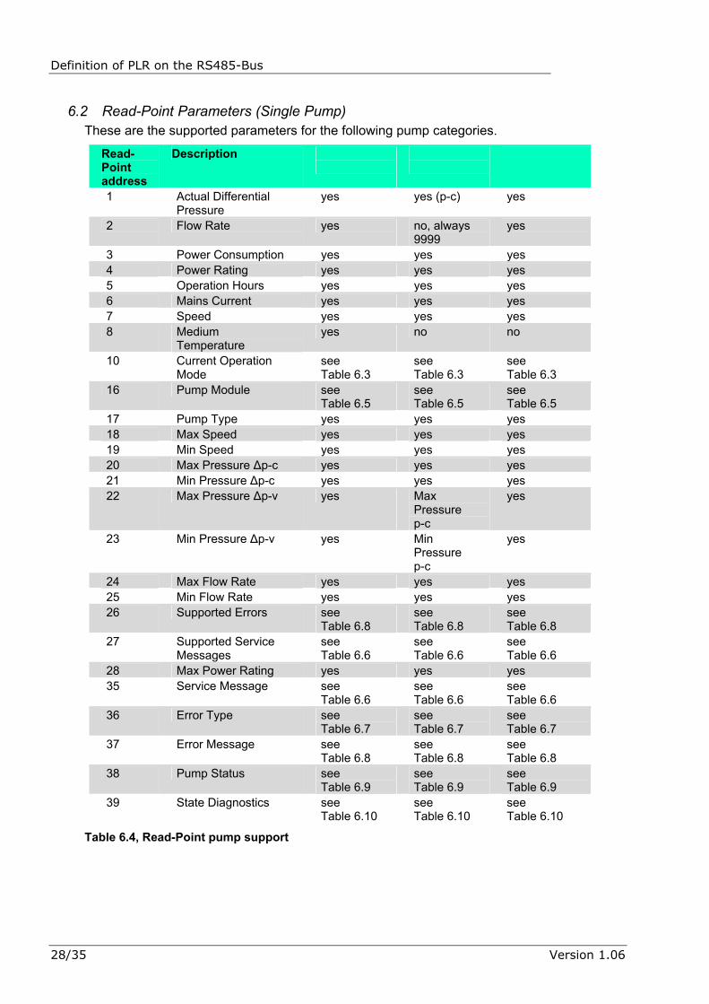
6.2 Read-Point Parameters (Single Pump) These are the supported parameters for the following pump categories.
Read-Point address
Description
1 Actual Differential Pressure
yes yes (p-c) yes
2 Flow Rate yes no, always 9999
yes
3 Power Consumption yes yes yes 4 Power Rating yes yes yes 5 Operation Hours yes yes yes 6 Mains Current yes yes yes 7 Speed yes yes yes 8 Medium
Temperature yes no no
10 Current Operation Mode
see Table 6.3
see Table 6.3
see Table 6.3
16 Pump Module see Table 6.5
see Table 6.5
see Table 6.5
17 Pump Type yes yes yes 18 Max Speed yes yes yes 19 Min Speed yes yes yes 20 Max Pressure ∆p-c yes yes yes 21 Min Pressure ∆p-c yes yes yes 22 Max Pressure ∆p-v yes Max
Pressure p-c
yes
23 Min Pressure ∆p-v yes Min Pressure p-c
yes
24 Max Flow Rate yes yes yes 25 Min Flow Rate yes yes yes 26 Supported Errors see
Table 6.8 see Table 6.8
see Table 6.8
27 Supported Service Messages
see Table 6.6
see Table 6.6
see Table 6.6
28 Max Power Rating yes yes yes 35 Service Message see
Table 6.6 see Table 6.6
see Table 6.6
36 Error Type see Table 6.7
see Table 6.7
see Table 6.7
37 Error Message see Table 6.8
see Table 6.8
see Table 6.8
38 Pump Status see Table 6.9
see Table 6.9
see Table 6.9
39 State Diagnostics see Table 6.10
see Table 6.10
see Table 6.10
Table 6.4, Read-Point pump support
28/35 Version 1.06

Definition of PLR on the RS485-Bus
6.2.1 Pump Module Bit number
Bit = 1 Siriux,SXE
Multi-VE/HE, Multi-VSE
LRE,SIE
0 Pump is regulated with a frequency-converter
yes, always 1
yes, always 1
yes, always 1
Table 6.5, Pump Module Info support
6.2.2 Service Message Bit number
Bit = 1 Siriux,SXE Multi-VE,HEMulti-VSE
LRE,SIE
0 Service needed yes yes yes 1 Exchange bearing yes no,
always 0 no, always 0
2 Oil bearing yes no, always 0
no, always 0
3 Change sealing yes no, always 0
no, always 0
Table 6.6, Service Message bit set support
6.2.3 Error Type Bit number
Bit = 1 Siriux,SXE
Multi-VE/HE Multi-VSE
LRE,SIE
0 Module error yes yes yes 1 Motor error yes yes yes 2 Reserved yes yes yes 3 Pump error yes yes yes 4 Supply voltage error yes yes yes
Table 6.7, Error Type bit set support
Version 1.06 29/35

Definition of PLR on the RS485-Bus 6.2.4 Error Message
Bit number
Bit = 1 Siriux,SXE Multi-VE/HE Multi-VSE
LRE,SIE
0 Undervoltage yes yes yes 1 Overvoltage yes yes yes 2 One phase missing yes yes yes 3 Idle running yes yes no,
always 0 4 System pressure too
high yes no,
always 0 no, always 0
5 System pressure too low
yes no, always 0
no, always 0
8 Motor overheated yes yes yes 9 Motor error yes yes yes 10 Pump blocked yes yes yes 11 Module overheated yes yes yes 12 Module warning yes yes yes 13 Module error yes yes yes 14 Sensor malfunction yes yes,
(4-20mA) no, always 0
Table 6.8, Error Message bit set support
6.2.5 Pump Status Bit number
Bit = 1 Siriux, SXE
Multi-VE/HE Multi-VSE
LRE,SIE
0 Pump running yes yes yes 1 Rotation direction yes yes yes 2 Difference <>±10% yes yes yes 3 Extern off yes yes yes 4 Single/Double pump yes yes,
always 0 yes
5 Manual override yes yes yes 6 Q/H values invalid yes yes,
always 1 yes
7 Extern min yes no, always 0
no, always 0
13 Wink/Service yes yes yes
Table 6.9, Pump Status bit set support
30/35 Version 1.06
Definition of PLR on the RS485-Bus
6.2.6 State Diagnostics Bit number
Bit = 1 Siriux-SXE,
Multi-VE/HE Multi-VSE
LRE,SIE
0 Pump or module error yes yes yes 1 Supply error yes yes yes 3 Max regulation limit
reached yes yes yes
4 Min regulation limit reached
yes yes yes
6 Set value out of range yes yes yes 8 Manual override yes yes yes 10 Pump running yes yes yes
Table 6.10, State diagnostics bit set support
6.3 Read-Point Parameters (special for a Double Pump) These are the supported parameters for the following pump categories.
Read-Point address
Description Siriux, SXE
Multi-VE/HE, Multi-VSE
LRE,SIE
9 Operating Hours DP
yes always 0 yes
65 Actual Differential Pressure (Slave)
yes yes yes
66 Flow Rate (Slave)
yes yes yes
67 Power Consumption (Slave)
yes yes yes
68 Power Rating (Slave)
yes yes yes
69 Operating Hours (Slave)
yes yes yes
70 Mains Current (Slave)
yes yes yes
71 Speed (Slave) yes yes yes 80 Pump Module
(Slave) see Table 6.5
see Table 6.5
see Table 6.5
81 Pump Type (Slave)
yes yes yes
100 Error Type (Slave)
see Table 6.7
see Table 6.7
see Table 6.7
102 Pump Status (Slave)
see Table 6.9
see Table 6.9
see Table 6.9
Table 6.11, Double Pump specific Read-Point addresses support
Version 1.06 31/35

Definition of PLR on the RS485-Bus
7 Transaction Examples
7.1 Single Pump
7.1.1 Example 1: Simple Write Sending the commands Pump On, Operation Mode ∆p-c and a set value of 40% to the pump with address 1.
Request Description Value Response Description Value Address 1 Address 1 Packet type 3 Packet type 0 Number of Write-Points 3 Number of Read-Points 0 Write-Point Pump command
40 Checksum 1
Type 1 Value (Low Byte) 9 Value (High Byte) 0 Write-Point Operation Mode
42
Type 1 Value (Low Byte) 3 Value (High Byte) 0 Write-Point 1 Type 32 Value, Low 80 Value, High 0 Number of Read-Points 0 Checksum 216
Table 7.1, a simple Write example
7.1.2 Example 2: Simple Read Reading the Actual Differential Pressure and the Power Rating from the pump with address 10. The pump answers that it is running with a pressure of 4,5 m WS and has a power rating of 550 W.
Request Description Value Response Description Value Address 10 Address 10 Packet type 3 Packet type 0 Number of Write-Points 0 Number of Read-Points 2 Number of Read-Points 2 Read-Point Act. Diff.
Pressure 1
Read-Point Act. Diff. Pressure
1 Type 32
Read-Point Power Rating 4 Value (Low Byte) 45 Checksum 20 Value (High Byte) 0 Read-Point Power Rating 4 Type 3 Value (Low Byte) 38 Value (High Byte) 2 Checksum 137
Table 7.2, a simple read example
32/35 Version 1.06

Definition of PLR on the RS485-Bus
7.1.3 A Read/Write example with unanswered data Sending a set value of 50% and reading the Flow Rate and Medium Temperature. The pump does not support Temperature and does not answer this Read-Point. And the pump is in an operation mode that does not support Flow Rate so it returns the value 9999 (999.9 m³/h).
Request Description Value Response Description Value Address 10 Address 10 Packet type 3 Packet type 0 Number of Write-Points 1 Number of Read-Points 1 Write-Point 1 Read-Point Flow Rate 2 Type 32 Type 32 Value, Low 100 Value (Low Byte) 15 Value, High 0 Value (High Byte) 39 Number of Read-Points 2 Checksum 99 Read-Point Flow Rate 2 Read-Point Medium Temperature
8
Checksum 159
Table 7.3, a read write example with unanswered data
7.2 Double Pump The difference between a single pump and a double pump is that one bit is set in Status register (Read-Point 38) and that more Read-Points are accessible.
7.2.1 Example 4: Simple Read Reading Pump Status and Operating Hours DP from the pump with address 0. The pump reports that it is off, that it is a double pump and that it has been running for 14580 hours.
Request Description Value Response Description Value Address 0 Address 0 Packet type 3 Packet type 0 Number of Write-Points 0 Number of Read-Points 2 Number of Read-Points 2 Read-Point Pump Status 38 Read-Point Pump Status 38 Type 3 Read-Point Operating Hours DP
9 Value (Low Byte) 16
Checksum 52 Value (High Byte) 0 Read-Point Operating
Hours DP 9
Type 33 Value (Low Byte) 178 Value (High Byte) 5 Checksum 28
Table 7.4, a read write example to a double pump
Version 1.06 33/35

Version 1.06 35/35