Embed Size (px)
Citation preview
1
CHAPTER 2
MOMENT OF INERTIA
2.1 Definition of Moment of Inertia
Consider a straight line (the "axis") and a set of point masses K,,, 321 mmm such that the
distance of the mass mi from the axis is ri . The quantity 2
ii rm is the second moment of the i th
mass with respect to (or "about") the axis, and the sum 2
ii rm∑ is the second moment of mass of
all the masses with respect to the axis.
Apart from some subtleties encountered in general relativity, the word "inertia" is synonymous
with mass - the inertia of a body is merely the ratio of an applied force to the resulting
acceleration. Thus 2
ii rm∑ can also be called the second moment of inertia. The second moment
of inertia is discussed so much in mechanics that it is usually referred to as just "the" moment of
inertia.
In this chapter we shall consider how to calculate the (second) moment of inertia for different
sizes and shapes of body, as well as certain associated theorems. But the question should be
asked: "What is the purpose of calculating the squares of the distances of lots of particles from
an axis, multiplying these squares by the mass of each, and adding them all together? Is this
merely a pointless make-work exercise in arithmetic? Might one just as well, for all the good it
does, calculate the sum ii rm∑ 2 ? Does 2
ii rm∑ have any physical significance?"
2.2 Meaning of Rotational Inertia.
If a force acts of a body, the body will accelerate. The ratio of the applied force to the resulting
acceleration is the inertia (or mass) of the body.
If a torque acts on a body that can rotate freely about some axis, the body will undergo an
angular acceleration. The ratio of the applied torque to the resulting angular acceleration is the
rotational inertia of the body. It depends not only on the mass of the body, but also on how that
mass is distributed with respect to the axis.
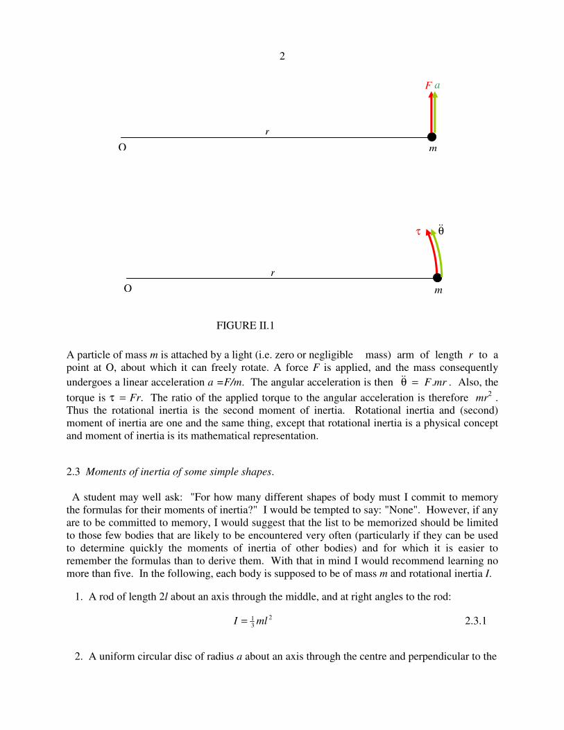
Consider the system shown in figure II.1.
2
A particle of mass m is attached by a light (i.e. zero or negligible mass) arm of length r to a
point at O, about which it can freely rotate. A force F is applied, and the mass consequently
undergoes a linear acceleration a =F/m. The angular acceleration is then mrF.=θ&& . Also, the
torque is τ = Fr. The ratio of the applied torque to the angular acceleration is therefore mr2 .
Thus the rotational inertia is the second moment of inertia. Rotational inertia and (second)
moment of inertia are one and the same thing, except that rotational inertia is a physical concept
and moment of inertia is its mathematical representation.
2.3 Moments of inertia of some simple shapes.
A student may well ask: "For how many different shapes of body must I commit to memory
the formulas for their moments of inertia?" I would be tempted to say: "None". However, if any
are to be committed to memory, I would suggest that the list to be memorized should be limited
to those few bodies that are likely to be encountered very often (particularly if they can be used
to determine quickly the moments of inertia of other bodies) and for which it is easier to
remember the formulas than to derive them. With that in mind I would recommend learning no
more than five. In the following, each body is supposed to be of mass m and rotational inertia I.
1. A rod of length 2l about an axis through the middle, and at right angles to the rod:
I ml= 13
2 2.3.1
2. A uniform circular disc of radius a about an axis through the centre and perpendicular to the
O
r
m
F a
O
r
m
θ&& τ
FIGURE II.1
3
plane of the disc:
I ma= 12
2 2.3.2
3. A uniform right-angled triangular lamina about one of its shorter sides - i.e. not the
hypotenuse. The other not-hypotenuse side is of length a:
I ma= 16
2 2.3.3
4. A uniform solid sphere of radius a about an axis through the centre.
I ma= 25
2 2.3.4
5. A uniform spherical shell of radius a about an axis through the centre.
I ma= 23
2 2.3.5
I shall now derive the first three of these by calculus. The derivations for the spheres will be left
until later.
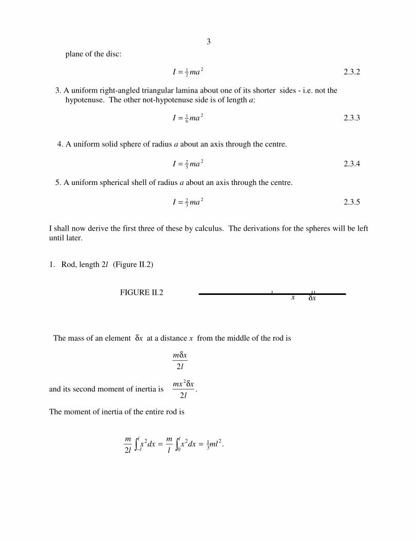
1. Rod, length 2l (Figure II.2)
The mass of an element δx at a distance x from the middle of the rod is
m x
l
δ
2
and its second moment of inertia is mx x
l
2
2
δ.
The moment of inertia of the entire rod is
.2
2
0 3122mldxx
l
mdxx
l
m ll
l ∫∫ ==−
x δx FIGURE II.2
4
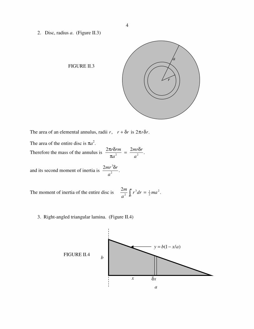
2. Disc, radius a. (Figure II.3)
The area of an elemental annulus, radii r r r, + δ is 2π δr r.
The area of the entire disc is πa2.
Therefore the mass of the annulus is .22
22a
rmr
a
mrr δ=
π
δπ
and its second moment of inertia is 2 3
2
mr r
a
δ.
The moment of inertia of the entire disc is .2
0
2
213
2 ∫ =a
madrra
m
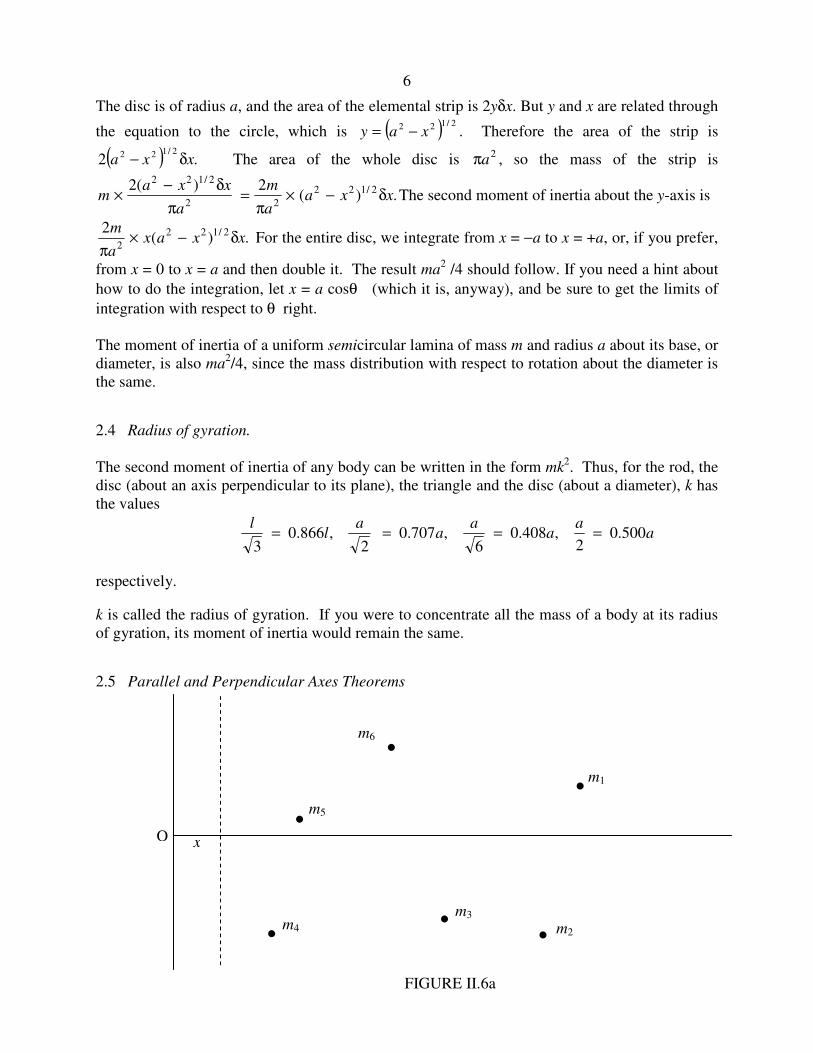
3. Right-angled triangular lamina. (Figure II.4)
r
a
FIGURE II.3
b
a
x δx
)/1( axby −=
FIGURE II.4

5
The equation to the hypotenuse is y b x a= −( / ).1
The area of the elemental strip is y x b x a xδ δ= −( / )1 and the area of the entire triangle is ab/2.
Therefore the mass of the elemental strip is 2
2
m a x x
a
( )− δ
and its second moment of inertia is 2 2
2
mx a x x
a
( ).
− δ
The second moment of inertia of the entire triangle is the integral of this from x = 0 to x = a,
which is ma2 /6.
Uniform circular lamina about a diameter.
For the sake of one more bit of integration practice, we shall now use the same argument to show
that the moment of inertia of a uniform circular disc about a diameter is ma2/4. However, we
shall see later that it is not necessary to resort to integral calculus to arrive at this result, nor is it
necessary to commit the result to memory. In a little while it will become immediately apparent
and patently obvious, with no calculation, that the moment of inertia must be ma2/4. However,
for the time being, let us have some more calculus practice. See figure II.5.
FIGURE II.5
6
The disc is of radius a, and the area of the elemental strip is 2yδx. But y and x are related through
the equation to the circle, which is ( ) 2/122 xay −= . Therefore the area of the strip is
( ) .22/122 xxa δ− The area of the whole disc is 2
aπ , so the mass of the strip is
.)(2)(2 2/122
22
2/122
xxaa
m
a
xxam δ−×
π=
π
δ−× The second moment of inertia about the y-axis is
.)(2 2/122
2xxax
a
mδ−×
π For the entire disc, we integrate from x = −a to x = +a, or, if you prefer,
from x = 0 to x = a and then double it. The result ma2 /4 should follow. If you need a hint about
how to do the integration, let x = a cosθ (which it is, anyway), and be sure to get the limits of
integration with respect to θ right.
The moment of inertia of a uniform semicircular lamina of mass m and radius a about its base, or
diameter, is also ma2/4, since the mass distribution with respect to rotation about the diameter is
the same.
2.4 Radius of gyration.
The second moment of inertia of any body can be written in the form mk2. Thus, for the rod, the
disc (about an axis perpendicular to its plane), the triangle and the disc (about a diameter), k has
the values
aa
aa
aa
ll
500.02
,408.06
,707.02
,866.03
====
respectively.
k is called the radius of gyration. If you were to concentrate all the mass of a body at its radius
of gyration, its moment of inertia would remain the same.
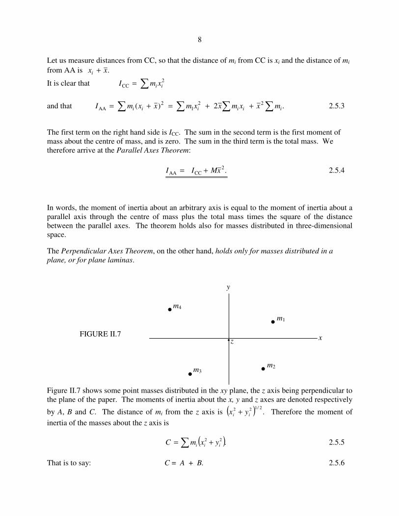
2.5 Parallel and Perpendicular Axes Theorems
·
·
· ·
··
m1
m2
m3 m4
m5
m6
FIGURE II.6a
x O

7
In figure II.6a, the two unbroken lines represent two fixed coordinate axes. I have drawn several
point masses K321 ,, mmm distributed in a plane. The x-coordinate of mass mi is xi. The dashed
line is moveable, and it x-coordinate is x, so that the distance of mi this line is .xxi − The
moment of inertia of the system of masses about the dashed line is
....)()()( 233
222
211 +−+−+−= xxmxxmxxmI 2.5.1
Now imagine what happens if the dashed line is moved to the right. The moment of inertia
decreases – and decreases - and decreases. But eventually the line finds itself to the right of
m4, and then of m5, and then of m6. After that is by no means obvious that the moment of
inertia is going to continue to decrease. Indeed, by this time it is clear that at some point I is
going to go through a minimum and then start to increase again as more and more of the masses
find themselves to the left of the dashed line. Just where is the dashed line when the moment of
inertia is a minimum? I’ll leave you to differentiate equation 2.5.1 with respect to x, and hence
show that I is least when
....
...
321
332211
+++
+++=
mmm
xmxmxmx 2.5.2
That is, the moment of inertia is least when xx = . That is, the moment of inertia is least for an
axis passing through the centre of mass.
In figure II.6b, the line CC passes through the centre of mass; the moment of inertia is least
about this line. The line AA is at a distance x from CC, and the moment of inertia is greater
about AA than about CC. The Parallel Axes Theorem tells us by how much.
·
·
· ·
··
m1
m2
m3 m4
m5
m6
FIGURE II.6b
x
A C
C A
8
Let us measure distances from CC, so that the distance of mi from CC is xi and the distance of mi
from AA is .xxi +
It is clear that 2CC ii xmI ∑=
and that .2)( 221
2AA ∑∑∑∑ ++=+= iiiiii mxxmxxmxxmI 2.5.3
The first term on the right hand side is ICC. The sum in the second term is the first moment of
mass about the centre of mass, and is zero. The sum in the third term is the total mass. We
therefore arrive at the Parallel Axes Theorem:
.2CCAA xMII +=
2.5.4
In words, the moment of inertia about an arbitrary axis is equal to the moment of inertia about a
parallel axis through the centre of mass plus the total mass times the square of the distance
between the parallel axes. The theorem holds also for masses distributed in three-dimensional
space.
The Perpendicular Axes Theorem, on the other hand, holds only for masses distributed in a
plane, or for plane laminas.
Figure II.7 shows some point masses distributed in the xy plane, the z axis being perpendicular to
the plane of the paper. The moments of inertia about the x, y and z axes are denoted respectively
by A, B and C. The distance of mi from the z axis is ( ) .2/122
ii yx + Therefore the moment of
inertia of the masses about the z axis is
( ).22
iii yxmC += ∑ 2.5.5
That is to say: C = A + B. 2.5.6
· · z
y
x
·
· ·
m4
m3
m1
m2
FIGURE II.7
9
This is the Perpendicular Axes Theorem. Note again very carefully that, unlike the parallel axes
theorem, this theorem applies only to plane laminas and to point masses distributed in a plane.
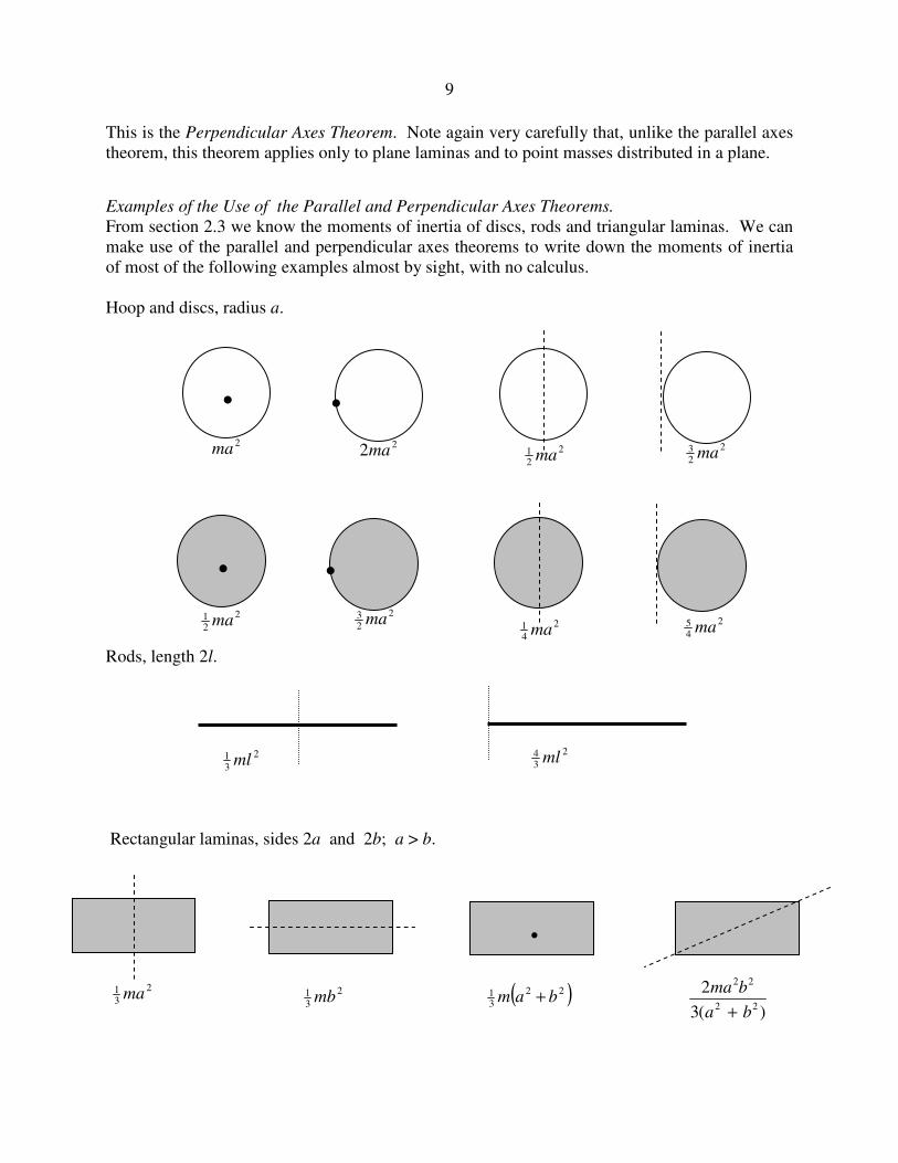
Examples of the Use of the Parallel and Perpendicular Axes Theorems.
From section 2.3 we know the moments of inertia of discs, rods and triangular laminas. We can
make use of the parallel and perpendicular axes theorems to write down the moments of inertia
of most of the following examples almost by sight, with no calculus.
Hoop and discs, radius a.
Rods, length 2l.
Rectangular laminas, sides 2a and 2b; a > b.
)(3
222
22
ba
bma
+
· ·
· ·
2ma 22ma 2
21 ma
2
23 ma
2
21 ma
2
23 ma 2
41 ma
2
45 ma
2
31 ml
2
34 ml
· 2
31 ma 2
31 mb ( )22
31 bam +

10
Square laminas, side 2a.
Triangular laminas.
·
2
32 ma 2
31 ma 2
31 ma 2
31 ma
a a a
2
61 ma
2
61 ma
a
b c
θ ·
· 2a
2
31 ma
( )222
361 cbam ++
a b
c
· a b
)(6
)( 33
ba
bam
+
+

11
( ) ( ) ( )( ) ( ) ( )22
6122
6122
61
22
6122
6122
61
3232
sin23tan3cot31
bamacmcbm
mcmbmaI
+=−=+=
θ−=θ+=θ+=
2.6 Three-dimensional solid figures. Spheres, cylinders, cones
Sphere, mass m, radius a.
The volume of an elemental cylinder of radii x x x, + δ , height 2y is
( ) .442/122 xxxaxyx δ−π=δπ Its mass is
( ) ( ) .34 2/122
33
34
2/122
xxxaa
m
a
xxxam δ−×=
π
δ−π× Its
second moment of inertia is ( ) .3 32/122
3xxxa
a
mδ−× The second moment of inertia of the entire
sphere is
( ) .3 2
523
2/1
0
22
3madxxxa
a
m a
=−× ∫
The moment of inertia of a uniform solid hemisphere of mass m and radius a about a diameter of
its base is also ,2
52 ma because the distribution of mass around the axis is the same as for a
complete sphere.
Problem: A hollow sphere is of mass M, external radius a and internal radius xa. Its rotational
inertia is 0.5 Ma2. Show that x is given by the solution of
1 − 5x 3
+ 4x 5 = 0
and calculate x to four significant figures. (Answer = 0.6836.)
x
y

12
Solid cylinder, mass m, radius a, length 2l
The mass of an elemental disc of thickness δx is m x
l
δ
2. Its moment of inertia about its diameter
is 1
4 2 8
22m x
la
ma x
l
δ δ= . Its moment of inertia about the dashed axis through the centre of the
cylinder is ( )
.8
4
28
222
2
l
xxamx
l
xm
l
xma δ+=
δ+
δ The moment of inertia of the entire cylinder
about the dashed axis is ( ) ( ).
8
42 2
312
41
0
22
laml
dxxaml
+=+
∫
In a similar manner it can be shown that the moment of inertia of a uniform solid triangular
prism of mass m, length 2l, cross section an equilateral triangle of side 2a about an axis through
its centre and perpendicular to its length is ( ).2
312
61 lam +
Solid cone, mass m, height h, base radius a.
The mass of the elemental disc of thickness δx is
x δx
2a
l l
x
y a
h
h
axy =
13
my x
a h
my x
a h× =
π δ
π
δ2
13
2
2
2
3.
Its second moment of inertia about the axis of the cone is
1
2
3 3
2
2
2
24
2× × =
my x
a hy
my x
a h
δ δ.
But y and x are related through yax
h= , so the moment of inertia of the elemental disk is
3
2
2 4
5
ma x x
h
δ.
The moment of inertia of the entire cone is
.10
3
2
3 2
0
4
5
2 madxx
h
mah
=∫
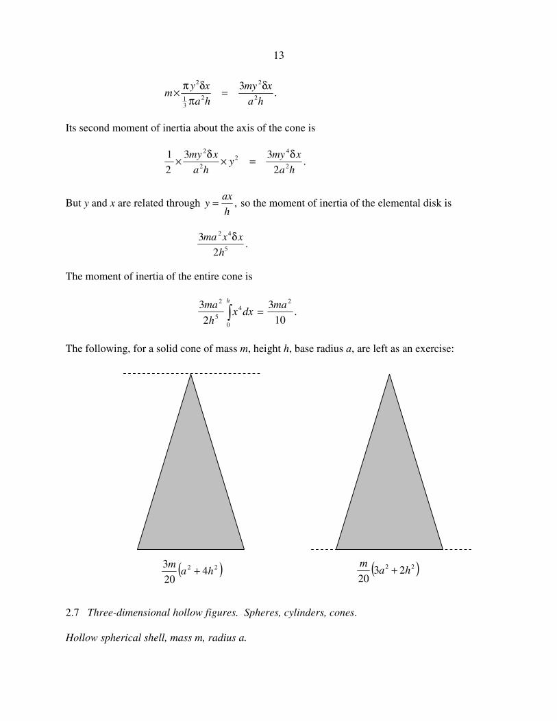
The following, for a solid cone of mass m, height h, base radius a, are left as an exercise:
2.7 Three-dimensional hollow figures. Spheres, cylinders, cones.
Hollow spherical shell, mass m, radius a.
( )22 420
3ha
m+ ( )22 23
20ha
m+

14
The area of the elemental zone is 2 2π θδθa sin . Its mass is
.sin4
sin221
2
2
θδθ=π
θδθπ× m
a
am
Its moment of inertia is .sinsinsin 32
2122
21 θδθ=θ×θδθ maam
The moment of inertia of the entire spherical shell is
.sin 2
32
0
32
21 madma =θθ∫
π
This result can be used to calculate, by integration, the moment of inertia 2
52 ma of a solid
sphere. Or, if you start with 2
52 ma for a solid sphere, you can differentiate to find the result
2
32 ma for a hollow sphere. Write the moment of inertia for a solid sphere in terms of its density
rather than its mass. Then add a layer da and calculate the increase dI in the moment of inertia.
We can also use the moment of inertia for a hollow sphere ( 2
32 ma ) to calculate the moment of
inertia of a nonuniform solid sphere in which the density varies as )(rρ=ρ . For example, if
2
0 )/(1 ar−ρ=ρ , see if you can show that the mass of the sphere is 3
0467.2 aρ and that its
moment of inertia is 2
31 ma . A much easier method will be found in Section 19.
θ
θsina θδ← a
15
Using methods similar to that given for a solid cylinder, it is left as an exercise to show that the
moment of inertia of an open hollow cylinder about an axis perpendicular to its length passing
through its centre of mass is ( ),2
312
21 lam + where a is the radius and 2l is the length.
The moment of inertia of a baseless hollow cone of mass m, base radius a, about the axis of the
cone could be found by integration. However, those who have an understanding of the way in
which the moment of inertia depends on the distribution of mass should readily see, without
further ado, that the moment of inertia is 12
2ma . (Look at the cone from above; it looks just like
a disc, and indeed it has the same radial mass distribution as a uniform disc.)
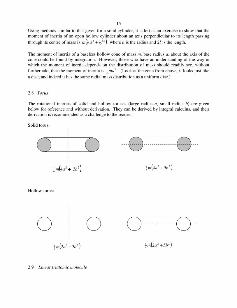
2.8 Torus
The rotational inertias of solid and hollow toruses (large radius a, small radius b) are given
below for reference and without derivation. They can be derived by integral calculus, and their
derivation is recommended as a challenge to the reader.
Solid torus:
Hollow torus:
2.9 Linear triatomic molecule
(((( ))))22
41 34 bam ++++ ( )22
81 54 bam +
( )22
21 32 bam +
( )22
41 52 bam +

16
Here is an interesting problem. It should be straightforward to calculate the rotational inertia of
the above molecule with respect to an axis perpendicular to the molecule and passing through the
centre of mass. In practice it is quite easy to measure the rotational inertia very precisely from
the spacing between the lines in a molecular band in the infrared region of the spectrum. If you
know the three masses (which you do if you know the atoms that make up the molecule) can you
calculate the two interatomic spacings x and y ? That would require determining two unknown
quantities, x and y, from a single measurement of the rotational inertia, I. Evidently that cannot
be done; a second measurement is required. Can you suggest what might be done? We shall
answer that shortly. In the meantime, it is an exercise to show that the rotational inertia is given
by
ax hxy by c2 22 0+ + + = , 2.9.1
where ( ) Mmmma /321 += 2.9.2
Mmmh /31= 2.9.3
( ) Mmmmb /213 += 2.9.4
M m m m= + +1 2 3 2.9.5
c I= − 2.9.6
For example, suppose the molecule is the linear molecule OCS, and the three masses are 16, 12
and 32 respectively, and, from infrared spectroscopy, it is determined that the moment of inertia
is 20. (For this hypothetical illustrative example, I am not concerning myself with units). In that
case, equation 2.9.1 becomes
.02039.1460.1737.11 22 =−++ yxyx &&& 2.9.7
We need another equation to solve for x and y. What can be done chemically is to prepare an
isotopically-substituted molecule (isotopomer) such as 18
OCS, and measure its moment of inertia
from its spectrum, making the probably very justified assumption that the interatomic distances
are unaffected by the isotopic substitution. This results in a second equation:
a x h xy b y c' ' ' ' .2 22 0+ + + = 2.9.8
Let's suppose that the new moment of inertia is 21' =I , and I leave it to the reader to work out
the numerical values of a', h' and b' with the stern caution to retain all the decimal places on your
calculator. That is, do not round off the numbers until the very end of the calculation.
m1 m2 m3
x y

17
You now have two equations, 2.9.1 and 2.9.8, to solve for x and y. These are two simultaneous
quadratic equations, and it may be that some guidance in solving them would be helpful. I have
three suggestions.
1. Treat equation 2.9.1 as a quadratic equation in x and solve it for x in terms of y. Then
substitute this in equation 2.9.8. I expect you will very soon become bored with this
method and will want to try something a little less tedious.
2. You have two equations of the form S x y S x y( , ) , ' ( , )= =0 0. There are standard ways
of solving these iteratively by an extension of the Newton-Raphson process. This is
described, for example, in section 1.9 of Chapter 1 of my Celestial Mechanics notes, and
this general method for two or more nonlinear equations should be known by anyone who
expects to engage in much numerical calculation.
For this particular case, the detailed procedure would be as follows. This is an iterative method,
and it is first necessary to make a guess at the solutions for x and y. The guesses need not be
particularly good. That done, compute the following six quantities:
S x( ax 2hy ) by c2= + + +
'')'2'(' 2 cybyhxaxS +++=
S ax hyx = +2( )
S hx byy = +2( )
S a x h yx' ( ' ' )= +2
S h x b yy' ( ' ' )= +2
Here the subscripts denote the partial derivatives. Now if
x(true) = x(guess) + ε
and y(true) = y(guess) + η
the errors ε and η can be found from the solution of
S S Sx yε η+ + = 0
and S S Sx y' ' 'ε η+ + = 0
If we calculate FS S S Sy x x y
=−
1
' '
The solutions for the errors are

18
ε = −F S S S Sy y( ' ')
η = −F S S S Sx x( ' ' )
This will enable a better guess to be made, and the procedure can be repeated until the errors are
as small as desired. Generally only a very few iterations are required. If this is not the case, a
programming mistake is indicated.
3. While method 2 can be used for any nonlinear simultaneous equations, in this particular
case we have two simultaneous quadratic equations, and a little familiarity with conic
sections provides a rather nice method.
Thus, if S = 0 and S' = 0 are equations 2.9.1 and 2.9.8 respectively. Each of these
equations represents a conic section, and they intersect at four points. We wish to find the
point of intersection that lies in the all-positive quadrant - i.e. with x and y both positive.
Since the two conic sections are very similar, in order to calculate where they intersect it
is necessary to calculate with great accuracy. Therefore, do not round off the numbers
until the very end of the calculation. Form the equation c S cS' ' .− = 0 This is also a
quadratic equation representing a conic section passing through the four points.
Furthermore, it has no constant term, and it therefore represents the two straight lines that
pass through the four points. The equation can be factorized into two linear terms, αβ = 0,
where α = 0 and β = 0 are the two straight lines. Choose the one with positive slope and
solve it with S = 0 or with S' = 0 (or with both, as a check against arithmetic mistakes) to
find x and y. In this case, the solutions are x = 0.2529, y = 1.000.
2.10 Pendulums
In section 2.2, we discussed the physical meaning of the rotational inertia as being the ratio of
the applied torque to the resulting angular acceleration. In linear motion, we are familiar with
the equation F = ma. The corresponding equation when dealing with torques and angular
acceleration is θ=τ &&I . We are also familiar with the equation of motion for a mass vibrating at
the end of a spring of force constant .: kxxmk −=&& This is simple harmonic motion of period
2π m k/ . The mechanics of the torsion pendulum is similar. The torsion constant c of a wire is
the torque required to twist it through unit angle. If a mass is suspended from a torsion wire, and
the wire is twisted through an angle θ , the restoring torque will be cθ , and the equation of
motion is ,θ−=θ cI && which is simple harmonic motion of period 2π I c/ . The torsion
constant of a wire of circular cross-section, by the way, is proportional to its shear modulus, the
fourth power of its radius, and inversely as its length. The derivation of this takes a little trouble,
but it can be verified by dimensional analysis. Thus a thick wire is very much harder to twist
than a thin one. A wire of narrow rectangular cross-section, such as a strip or a ribbon has a
relatively small torsion constant.

19
Now let's look not at a torsion pendulum, but at a pendulum swinging about an axis under
gravity.
We suppose the pendulum, of mass m, is swinging about a point O, which is at a distance h from
the centre of mass C. The rotational inertia about O is I. The line OC makes an angle θ with the
vertical, so that the horizontal distance between O and C is h sin θ. The torque about O is
mgh sin ,θ so that the equation of motion is
.sin θ−=θ mghI && 2.10.1
For small angles, this is
.θ−=θ mghI && 2.10.2
This is simple harmonic motion of period
PI
mgh= 2π . 2.10.3
·
·
O
C
h
mg

20
We'll look at two examples - a uniform rod, and an arc of a circle.
First, a uniform rod.
The centre of mass is C. The rotational inertia about C is 13
2ml , so the rotational inertia about O
is I ml mh= +13
2 2 . If we substitute this in equation 2.10.3, we find for the period of small
oscillations
Pl h
gh=
+2
3
3
2 2
π . 2.10.4
This can be written
( )
,/
/31.
32
2
lh
lh
g
lP
+π= 2.10.5
or, if we write
g
l
P
32π
=P and h = h/l :
.31 2
h
hP
+= 2.10.6
The figure shows a graph of P versus h.
·
· O
C
h

21
Equation 2.10.6 can be written
hh
P 312 += 2.10.7
and, by differentiation of P2 with respect to h, we find that the period is least when .3/1=h
This least period is given by ,122 =P or P = 1.861.
Equation 2.10.7 can also be written
.013 22 =+− hPh 2.10.8
This quadratic equation shows that there are two positions of the support O that give rise to the
same period of small oscillations. The period is least when the two solutions of equation 2.10.8
are equal, and by the theory of quadratic equations, then, the least period is given by ,122 =P
as we also deduced by differentiation of equation 2.10.7, and this occurs when .3/1=h
For periods longer than this, there are two solutions for h. Let h1 be the smaller of these, and let
h2 be the larger. By the theory of quadratic equations, we have
2
31
21 Phh =+ 2.10.9

22
and .3/121 =hh 2.10.10
Let 12 hhH −= be the distance between two points O that give the same period of oscillation.
Then
( ) ( ) .9
124
4
21
2
12
2
12
2 −=−+=−=
PhhhhhhH 2.10.11
If we measure H for a given period P and recall the definition of P we see that this provides a
method for determining g. Although this is a common undergraduate laboratory exercise, the
graph shows that the minimum is very shallow and consequently H and hence g are very difficult
to measure with any precision.
For another example, let us look at a wire bent into the arc of a circle of radius a oscillating in a
vertical plane about its mid-point. In the figure, C is the centre of mass.
The rotational inertia about the centre of the circle is ma2. By two applications of the parallel
axes theorem, we see that the rotational inertia about the point of oscillation is
( ) .2222 mahmhhammaI =+−−= Thus, from equation 2.10.3 we find
Pa
g= 2
2π , 2.10.12
and the period is independent of the length of the arc.
2.11. Plane Laminas. Product moment. Translation of Axes (Parallel Axes Theorem).
We consider a set of point masses distributed in a plane, or a plane lamina. We have hitherto
met three second moments of inertia:
A m yi i=∑ 2 , 2.11.1
B m xi i=∑ 2 , 2.11.2
·
· C h
a-h

23
( ).22∑ += iii yxmC 2.11.3
These are respectively the moments of inertia about the x- and y-axes (assumed to be in the plane
of the masses or the lamina) and the z-axis (normal to the plane). Clearly, C = A + B, which is
the perpendicular axes theorem for a plane lamina.
We now introduce another quantity, H, called the product moment of inertia with respect to the
x- and y-axes, defined by
H m x yi i i=∑ . 2.11.4
We'll need sometime to ask ourselves whether this has any particular physical significance, or
whether it is merely something to calculate for the sake of passing the time of day. In the
meantime, the reader should recall the parallel axes theorems (Section 2.5) and, using arguments
similar to those given in that section, should derive
H H M x yC= + . 2.11.5
It may also be noted that equation 2.11.4 does not contain any squared terms and therefore the
product moment of inertia, depending on the distribution of masses, is just as likely to be a
negative quantity as a positive one.
We shall defer discussing the physical significance, if any, of the product moment until section
12. In the meantime let us try to calculate the product moment for a plane right triangular
lamina:
The area of the triangle is 12
ab and so the mass of the element δxδy is ,2
ab
yxM δδ where M is
the mass of the complete triangle. The product moment of the element with respect to the sides
OA, OB is ab
yxMxy δδ2 and so the product moment of the entire triangle is ∫∫ .
2xydxdy
ab
M We
have to consider carefully the limits of integration. We'll integrate first with respect to x ; that
O
B
A
x
y
a
b
24
is to say we integrate along the horizontal (y constant) strip from the side OB to the side AB.
That is to say we integrate xδx from where x = 0 to where .1
−=
b
yax The product moment is
therefore
( ) .1.2 2
2
21 dyay
ab
Mb
y
∫ −
We now have to add up all the horizontal strips from the side OA, where y = 0, to B, where y = b.
Thus
( )∫ −=b
b
ydyy
b
MaH
0
21 ,
which, after some algebra, comes to H Mab= 112
.
The coordinates of the centre of mass with respect to the sides OA, OB are ( )ba31
31 , , so that,
from equation 2.11.5, we find that the product moment with respect to axes parallel to OA, OB
and passing through the centre of mass is − 136
Mab.
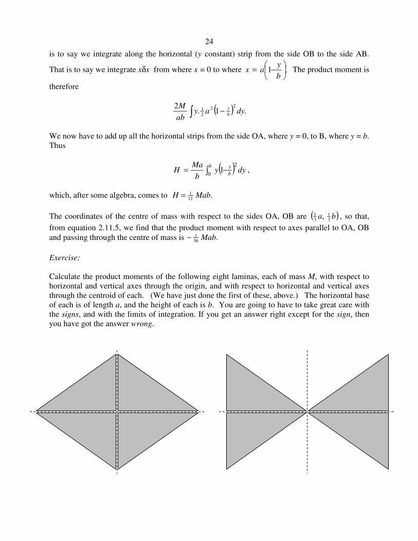
Exercise:
Calculate the product moments of the following eight laminas, each of mass M, with respect to
horizontal and vertical axes through the origin, and with respect to horizontal and vertical axes
through the centroid of each. (We have just done the first of these, above.) The horizontal base
of each is of length a, and the height of each is b. You are going to have to take great care with
the signs, and with the limits of integration. If you get an answer right except for the sign, then
you have got the answer wrong.

25
I make the answers as follows.
2.12 Rotation of Axes.
We start by recalling a result from elementary geometry. Consider two sets of axes Oxy and
Ox1y1, the latter being inclined at an angle θ to the former. Any point in the plane can be
described by the coordinates (x , y) or by (x1 , y1). These coordinates are related by a rotation
matrix:
,cossin
sincos
1
1
θθ−
θθ=
y
x
y
x 2.12.1
.cossin
sincos
1
1
θθ
θ−θ=
y
x
y
x 2.12.2
The rotation matrix is orthogonal; one of the several properties of an orthogonal matrix is that its
reciprocal is its transpose.
x
x1
y1
y
θ O
MabMab36
1
12
1 − MabMab36
141 + MabMab
36
1
12
1 +−
MabMab36
141 −− MabMab
36
1
12
1 +− MabMab36
1
12
1 −+ MabMab36
141 +
MabMab36
141 −−
26
Now let us apply this to the moments of inertia of a plane lamina. Let us suppose that the axes
are in the plane of the lamina and that O is the centre of mass of the lamina. A, B and H are the
moments of inertia with respect to the axes Oxy, and A1 , B1 and H1 are the moments of inertia
with respect to Ox1y1. Strictly speaking a lamina implies a continuous distribution of matter in a
plane, but, since matter, we are told, is composed of discrete atoms, there is little difficulty in
justifying treating a lamina as though it we a distribution of point masses in the plane. In any
case the results that follow are valid either for a collection of point masses in a plane or for a
genuine continuous lamina.
We have, by definition:
A my1 1
2=∑ 2.12.3
B mx1 1
2=∑ 2.12.4
H mx y1 1 1=∑ 2.12.5
Now let us apply equation 2.12.1 to equation 2.12.3:
( ) .coscossin2sincossin 22222
1 ∑∑ ∑∑ θ+θθ−θ=θ+θ−= mymxymxyxmA
That is to say (writing the third term first, and the first term last)
A A H B1
2 22= − +cos sin cos sin .θ θ θ θ 2.12.6
In a similar fashion, we obtain for the other two moments
B A H B1
2 22= + +sin sin cos cosθ θ θ θ 2.12.7
and ( ) .cossinsincoscossin 22
1 θθ−θ−θ+θθ= BHAH 2.12.8
It is usually more convenient to make use of trigonometric identities to write these as
( ) ( ) ,2sin2cos21
21
1 θ−θ−−+= HABABA 2.12.9
( ) ( ) ,2sin2cos21
21
1 θ+θ−++= HABABB 2.12.10
( ) .2sin2cos21
1 θ−−θ= ABHH 2.12.11
These equations enable us to calculate the moments of inertia with respect to the axes Ox1y1 if
we know the moments with respect to the axes Oxy.
Further, a matter of importance, we see, from equation 2.12.11, that if
27
tan ,22
θ =−
H
B A 2.12.12
the product moment H1 with respect to the axes Oxy is zero. This gives some physical meaning
to the product moment, namely: If we can find some axes (which we can, by means of equation
2.12.12) with respect to which the product moment is zero, these axes are called the principal
axes of the lamina, and the moments of inertia with respect to the principal axes are called the
principal moments of inertia. I shall use the symbols A0 and B0 for the principal moments of
inertia, and I shall adopt the convention that .00 BA ≤
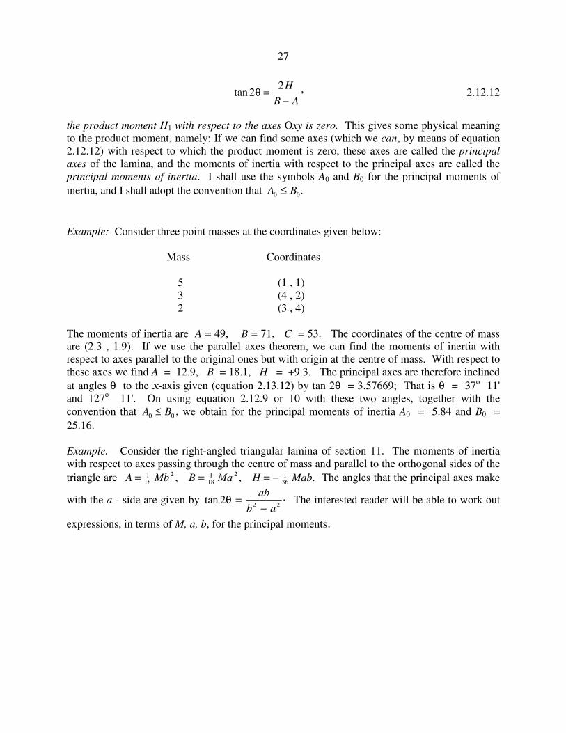
Example: Consider three point masses at the coordinates given below:
Mass Coordinates
5 (1 , 1)
3 (4 , 2)
2 (3 , 4)
The moments of inertia are A = 49, B = 71, C = 53. The coordinates of the centre of mass
are (2.3 , 1.9). If we use the parallel axes theorem, we can find the moments of inertia with
respect to axes parallel to the original ones but with origin at the centre of mass. With respect to
these axes we find A = 12.9, B = 18.1, H = +9.3. The principal axes are therefore inclined
at angles θ to the x-axis given (equation 2.13.12) by tan 2θ = 3.57669; That is θ = 37o 11'
and 127o 11'. On using equation 2.12.9 or 10 with these two angles, together with the
convention that A B0 0≤ , we obtain for the principal moments of inertia A0 = 5.84 and B0 =
25.16.
Example. Consider the right-angled triangular lamina of section 11. The moments of inertia
with respect to axes passing through the centre of mass and parallel to the orthogonal sides of the
triangle are A Mb B Ma H Mab= = = −118
2 118
2 136
, , . The angles that the principal axes make
with the a - side are given by .2tan22
ab
ab
−=θ The interested reader will be able to work out
expressions, in terms of M, a, b, for the principal moments.

28
2.13 Momental Ellipse
Consider a plane lamina such that its radius of gyration about some axis through the centre of
mass is k. Let P be a vector in the direction of that axis, originating at the centre of mass, given
by
rP ˆ2
k
a= 2.13.1
Here r̂ is a unit vector in the direction of interest; k is the radius of gyration, and a is an
arbitrary length introduced so that the dimensions of P are those of length, and the length of the
vector P is inversely proportional to the radius of gyration. The moment of inertia is
Mk Ma P2 4 2= / . That is to say
Ma
PA H B
4
2
2 22= − +cos sin cos sin ,θ θ θ θ 2.13.2
where A, H and B are the moments with respect to the x- and y-axes. Let (x , y) be the
coordinates of the tip of the vector P, so that x P= cosθ and y P= sin .θ Then
.2 224 ByHxyAxMa +−= 2.13.3
Thus, no matter what the shape of the lamina, however irregular and asymmetric, the tip of the
vector P traces out an ellipse, whose axes are inclined at angles
−
−
AB
H2tan 1
21 to the x-axis.
This is the momental ellipse, and the axes of the momental ellipse are the principal axes of the
lamina.
Example. Consider a regular n-gon. By symmetry the moment of inertia is the same about any
two axes in the plane inclined at 2π/n to each other. This is possible only if the momental ellipse
P
θ
29
is a circle. It follows that the moment of inertia of a uniform polygonal plane lamina is the same
about any axis in its plane and passing through its centroid.
Exercise. Show that the moment of inertia of a uniform plane n-gon of side 2a about any axis in
its plane and passing through its centroid is ( )( )./cot31 22
121 nma π+ What is this for a square?
For an equilateral triangle?
2.14. Eigenvectors and eigenvalues.
In sections 11-13, we have been considering some aspects of the moments of inertia of plane
laminas, and we have discussed such matters as rotation of axes, and such concepts as product
moments of inertia, principal axes, principal moments of inertia and the momental ellipse. We
next need to develop the same concepts with respect to three-dimensional solid bodies. In doing
so, we shall need to make use of the algebraic concepts of eigenvectors and eigenvalues. If you
are already familiar with such matters, you may want to skip this section and move on to the
next. If the ideas of eigenvalues and eigenvectors are new to you, or if you are a bit rusty with
them, this section may be helpful. I do assume that the reader is at least familiar with the
elementary rules of matrix multiplication.
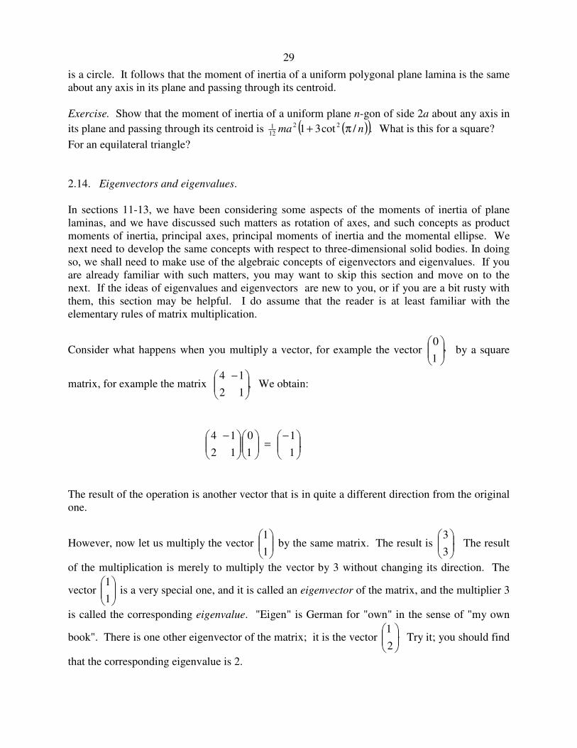
Consider what happens when you multiply a vector, for example the vector ,1
0
by a square
matrix, for example the matrix ,12
14
− We obtain:
.1
1
1
0
12
14
−=
−
The result of the operation is another vector that is in quite a different direction from the original
one.
However, now let us multiply the vector
1
1 by the same matrix. The result is .
3
3
The result
of the multiplication is merely to multiply the vector by 3 without changing its direction. The
vector
1
1 is a very special one, and it is called an eigenvector of the matrix, and the multiplier 3
is called the corresponding eigenvalue. "Eigen" is German for "own" in the sense of "my own
book". There is one other eigenvector of the matrix; it is the vector .2
1
Try it; you should find
that the corresponding eigenvalue is 2.
30
In short, given a square matrix A, if you can find a vector a such that Aa = λa, where λ is
merely a scalar multiplier that does not change the direction of the vector a, then a is an
eigenvector and λ is the corresponding eigenvalue.
In the above, I told you what the two eigenvectors were, and you were able to verify that they
were indeed eigenvectors and you were able to find their eigenvalues by straightforward
arithmetic. But, what if I hadn't told you the eigenvectors? How would you find them?
Let
=
2221
1211
AA
AAA and let
=
2
1
x
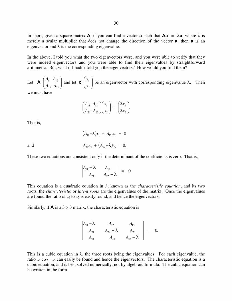
xx be an eigenvector with corresponding eigenvalue λ. Then
we must have
.2
1
2
1
2221
1211
λ
λ=
x
x
x
x
AA
AA
That is,
( ) 0212111 =+λ− xAxA
and ( ) .0222121 =λ−+ xAxA
These two equations are consistent only if the determinant of the coefficients is zero. That is,
A A
A A
11 12
21 22
0−
−=
λ
λ.
This equation is a quadratic equation in λ, known as the characteristic equation, and its two
roots, the characteristic or latent roots are the eigenvalues of the matrix. Once the eigenvalues
are found the ratio of x1 to x2 is easily found, and hence the eigenvectors.
Similarly, if A is a 3 × 3 matrix, the characteristic equation is
A A A
A A A
A A A
11 12 13
21 22 23
31 32 33
0
−
−
−
=
λ
λ
λ
.
This is a cubic equation in λ, the three roots being the eigenvalues. For each eigenvalue, the
ratio x1 : x2 : x3 can easily be found and hence the eigenvectors. The characteristic equation is a
cubic equation, and is best solved numerically, not by algebraic formula. The cubic equation can
be written in the form

31
λ λ λ3
2
2
1 0 0+ + + =a a a ,
and the solutions can be checked from the following results from the theory of equations:
λ λ λ1 2 3 2+ + = − a ,
λ λ λ λ λ λ2 3 3 1 1 2 1+ + = a ,
λ λ λ1 2 3 0= − a .
2.15. Solid body.
The moments of inertia of a collection of point masses distributed in three-dimensional space (or
of a solid three-dimensional body, which, after all, is a collection of point masses (atoms)) with
respect to axes Oxyz are:
( ) ∑∑ =+= myzFzymA22
( ) ∑∑ =+= mzxGxzmB22
( )∑ ∑=+= mxyHyxmC22
Suppose that A, B, C, F, G, H, are the moments and products of inertia with respect to axes
whose origin is at the centre of mass. The parallel axes theorems (which the reader should
prove) are as follows: Let P be some point not at the centre of mass, such that the coordinates of
the centre of mass with respect to axes parallel to the axes Oxyz but with origin at P are ( )zyx ,, .
Then the moments and products of inertia with respect to the axes through P are
( )( )( ) yxMHyxMC
xzMGxzMB
zyMFzyMA
+++
+++
+++
22
22
22
where M is the total mass.
Unless stated otherwise, in what follows we shall suppose that the moments and products of
inertia under discussion are referred to a set of axes with the centre of mass as origin.

32
2.16 Rotation of axes - three dimensions.
Let Oxyz be one set of mutually orthogonal axes, and let Ox1y1z1 be another set of axes inclined
to the first. The coordinates (x1 , y1 , z1 ) of a point with respect to the second basis set are
related to the coordinates (x, y, z ) with respect to the first by
.
333231
232221
131211
1
1
1
=
z
y
x
ccc
ccc
ccc
z
y
x
2.16.1
Here the cij are the cosines of the angles between the axes of one basis set with respect to the
axes of the other. For example, c12 is the cosine of the angle between Ox1 and Oy. c23 is the
cosine of the angles between Oy1 and Oz.
Some readers may know how to express these cosines in terms of complicated expressions
involving the Eulerian angles. While these are important, they are not essential for following the
present development, so we shall not make use of the Eulerian angles just here.
The matrix of direction cosines is orthogonal. Among the several properties of an orthogonal
matrix is the fact that its reciprocal (inverse) is equal to its transpose - i.e. the reciprocal of an
orthogonal matrix is found merely my interchanging the rows and columns. This enables us
easily to find (x , y , z ) in terms of (x1 , y1 , z1 ).
A number of other properties of an orthogonal matrix are useful in detecting, locating and even
correcting arithmetic mistakes in computing the elements. These properties are
1. The sum of the squares of the elements in any row or column is unity. This merely
expresses the fact that the magnitude of a unit vector along any of the six axes is indeed
unity.
2. The sum of the products of corresponding elements of any two rows or of any two columns
is zero. This merely expresses the fact that the scalar product of any two orthogonal
vectors is zero. It will be noted that checking for property 1 will not detect any mistakes in
sign of the elements, whereas checking for property 2 will do so.
3. Every element is equal to ± its own cofactor. This expresses the fact that the cross product
of two unit orthogonal vectors is equal to the third.
4. The determinant of the matrix is ± 1. If the sign is negative, it means that the chiralities
(handedness) of the two basis sets of axes are opposite; i.e. one of them is a right-handed
set and the other is a left-handed set. It is usually convenient to choose both sets as right-
handed.

33
If it is possible to find a set of axes with respect to which the product moments F, G and H are all
zero, these axes are called the principal axes of the body, and the moments of inertia with respect
to these axes are the principal moments of inertia, for which we shall use the notation A0 , B0 ,
C0, with the convention A B C0 0 0≤ ≤ . We shall see shortly that it is indeed possible, and we
shall show how to do it. A vector whose length is inversely proportional to the radius of gyration
traces out in space an ellipsoid, known as the momental ellipsoid.
In the study of solid body rotation (whether by astronomers studying the rotation of asteroids or
by chemists studying the rotation of molecules) bodies are classified as follows.
1. A B C0 0 0≠ ≠ The ellipsoid is a triaxial ellipsoid, and the body is an asymmetric top.
2. A B C0 0 0< = The ellipsoid is a prolate spheroid and the body is a prolate symmetric top.
3. A B C0 0 0= < The ellipsoid is an oblate spheroid and the body is an oblate symmetric top.
4. A B C0 0 0= = The ellipsoid is a sphere and the body is a spherical top.
5. One moment is zero. The ellipsoid is an infinite elliptical cylinder, and the body is a linear
top.
Example. We know from section 2.5 that the moment of inertia of a plane square lamina of side
2a about an axis through its centroid and perpendicular to its area is 23
2ma , and it will hence be
obvious that the moment of inertia of a uniform solid cube of side 2a about an axis passing
through the mid-points of opposite sides is also 23
2ma . It will clearly be the same about an axis
passing through the mid-points of any pairs of opposite sides. Therefore the cube is a spherical
top and the momental ellipsoid is a sphere. Therefore the moment of inertia of a uniform solid
cube about any axis through its centre (including, for example, a diagonal) is also 23
2ma .
Example. What is the ratio of the length to the diameter of a uniform solid cylinder such that it
is a spherical top? [Answer: I make it 3 2 0 866/ . .]=
Let us note in passing that
( ) ,22 2222 ∑∑ =++=++ mrzyxmCBA 2.16.2
which is independent of the orientation of the basis axes In other words, regardless of how A,
B and C may depend on the orientation of the axes with respect to the body, the sum A B C+ +
is invariant under a rotation of axes.
We shall deal with the determination of the principal axes in section 2.18 - but don't skip
section 2.17.
2.17 Solid Body Rotation. The Inertia Tensor.

34
It is intended that this chapter should be limited to the calculation of the moments of inertia of
bodies of various shapes, and not with the huge subject of the rotational dynamics of solid
bodies, which requires a chapter on its own. In this section I mention merely for interest two
small topics involving the principal axes, and a third topic in a bit more detail as necessary
before proceeding to section 2.18.
Everyone knows that the relation between translational kinetic energy and linear momentum is
( ).2/2 mpE = Similarly rotational kinetic energy is related to angular momentum L by
( ),2/2 ILE = where I is the moment of inertia. If an isolated body (such as an asteroid) is
rotating about a non-principal axis, it will be subject to internal stresses. If the body is nonrigid
this will result in distortions (strains) which may cause the body to vibrate. If in addition the
body is inelastic the vibrations will rapidly die out (if the damping is greater than critical
damping, indeed, the body will not even vibrate). Energy that was originally rotational kinetic
energy will be converted to heat (which will be radiated away.) The body loses rotational kinetic
energy. In the absence of external torques, however, L remains constant. Therefore, while E
diminishes, I increases. The body adjusts its rotation until it is rotating around its axis of
maximum moment of inertia, at which time there are no further stresses, and the situation
remains stable.
In general the rotational motion of a solid body whose momental ellipse is triaxial is quite
complicated and chaotic, with the body tumbling over and over in apparently random fashion.
However, if the body is nonrigid and inelastic (as all real bodies are in practice), it will
eventually end up rotating about its axis of maximum moment of inertia. The time taken for a
body, initially tumbling chaotically over and over, until it reaches its final blissful state of
rotation about its axis of maximum moment of inertia, depends on how fast it is rotating. For
most irregular small asteroids the time taken is comparable to or longer than the age of formation
of the solar system, so that it is not surprising to find some asteroids with non-principal axis
(NPA) rotation. However, a few rapidly-rotating NPA asteroids have been discovered, and, for
rapid rotators, one would expect PA rotation to have been reached a long time ago. It is thought
that something (such as a collision) must have happened to these rapidly-rotating NPA asteroids
relatively recently in the history of the solar system.
Another interesting topic is that of the stability of a rigid rotator that is rotating about a
principal axis, against small perturbations from its rotational state. Although I do not prove it
here (the proof can be done either mathematically, or by a qualitative argument) rotation about
either of the axes of maximum or of minimum moment of inertia is stable, whereas rotation
about the intermediate axis is unstable. The reader can observe this for him- or herself. Find
anything that is triaxial - such as a small block of wood shaped as a rectangular parallelepiped
with unequal sides. Identify the axes of greatest, least and intermediate moment of inertia. Toss
the body up in the air at the same time setting it rotating about one or the other of these axes, and
you will be able to see for yourself that the rotation is stable in two cases but unstable in the
third.
I now deal with a third topic in rather more detail, namely the relation between angular
momentum L and angular velocity ωωωω. The reader will be familiar from elementary (and two-
dimensional) mechanics with the relation .ω= IL What we are going to find in the three-

35
dimensional solid-body case is that the relation is L = Iωωωω. Here L and ωωωω are, of course, vectors,
but they are not necessarily parallel to each other. They are parallel only if the body is rotating
about a principal axis of rotation. The quantity I is a tensor known as the inertia tensor. Readers
will be familiar with the equation F = ma. Here the two vectors are in the same direction, and
m is a scalar quantity that does not change the direction of the vector that it multiplies. A tensor
usually (unless its matrix representation is diagonal) changes the direction as well as the
magnitude of the vector that it multiplies. The reader might like to think of other examples of
tensors in physics. There are several. One that comes to mind is the permittivity of an
anisotropic crystal; in the equation D = εεεεE, D and E are not parallel unless they are both
directed along one of the crystallographic axes.
If there are no external torques acting on a body, L is constant in both magnitude and direction.
The instantaneous angular velocity vector, however, is not fixed either in space or with respect to
the body - unless the body is rotating about a principal axis and the inertia tensor is diagonal.
So much for a preview and a qualitative description. Now down to work.
I am going to have to assume familiarity with the equation for the components of the cross
product of two vectors:
A × B = ( ) ( ) ( ) .ˆˆˆ zyx xyyxzxxzyzzy BABABABABABA −+−+− 2.17.1
I am also going to assume that the reader knows that the angular momentum of a particle of
mass m at position vector r (components ),,( zyx ) and moving with velocity v (components
( )zyx &&& ,, ) is mr×v. For a collection of particles, (or an extended solid body, which, I'm told,
consists of a collection of particles called atoms), the angular momentum is
L r v= ×∑m
= ( ) ( ) ( )[ ]∑ −+−+− zyx ˆˆˆ xyyxmzxxzmyzzym &&&&&&
I also assume that the relation between linear velocity v ( )zyx &&& ,, and angular velocity
ω ω ω ω ( )zyx ωωω ,, is understood to be v = ω ω ω ω × r, so that, for example, xyz yx ω−ω=& . Then
L = ( ) ( )( ) ( ) ( )[ ]∑ ++ω−ω−ω−ω zyx ˆ.etcˆ.etcˆzxzxyym xzyx
= ( ) .etcˆ22 +ω+ω−ω−ω ∑ ∑ ∑ ∑ xmzmzxmxymy xzyx
= ( ) ( ) ( )zyx ˆˆˆ ++ω−ω−ω zyx GHA .
Finally, we obtain
36
ω
ω
ω
−−
−−
−−
=
=
z
y
x
z
y
x
CFG
FBH
GHA
L
L
L
L 2.17.2
This is the equation L = Iω ω ω ω referred to above. The inertia tensor is sometimes written in the
form
,
=
zzyzxz
yzyyxy
xzxyxx
III
III
III
I
so that, for example, .HI xy −= It is a symmetric matrix (but it is not an orthogonal matrix).
2.18. Determination of the Principal Axes.
We now need to address ourselves to the determination of the principal axes. Unlike the two-
dimensional case, we do not have a nice, simple explicit expression similar to equation 2.12.12
to calculate the orientations of the principal axes. The determination is best done through a
numerical example.
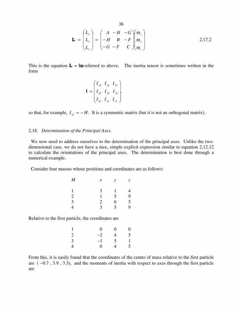
Consider four masses whose positions and coordinates are as follows:
M x y z
1 3 1 4
2 1 5 9
3 2 6 5
4 3 5 9
Relative to the first particle, the coordinates are
1 0 0 0
2 −2 4 5
3 −1 5 1
4 0 4 5
From this, it is easily found that the coordinates of the centre of mass relative to the first particle
are ( −0.7 , 3.9 , 3.3), and the moments of inertia with respect to axes through the first particle
are

37
A
B
C
F
G
H
=
=
=
=
= −
= −
324
164
182
135
23
31
From the parallel axes theorems we can find the moments of inertia with respect to axes passing
through the centre of mass:
A
B
C
F
G
H
=
=
=
=
=
= −
63 0
50 2
25 0
6 3
0 1
3 7
.
.
.
.
.
.
The inertia tensor is therefore
−−
−
−
0.253.61.0
3.62.507.3
1.07.30.63
We understand from what has been written previously that if ωωωω, the instantaneous angular
velocity vector, is along any of the principal axes, then Iωωωω will be in the same direction as ωωωω. In
other words, if ( )nml ,, are the direction cosines of a principal axis, then
,
λ=
−−
−−
−−
n
m
l
n
m
l
CFG
FBH
GHA
where λ is a scalar quantity. In other words, a vector with components l, m, n (direction cosines
of a principal axis) is an eigenvector of the inertia tensor, and λ is the corresponding principal
moment of inertia. There will be three eigenvectors (at right angles to each other) and three
corresponding eigenvalues, which we’ll initially call λ1, λ2, λ3, though, as soon as we know
which is the largest and which the smallest, we'll call A B C0 0 0, , , according to our convention
A B C0 0 0≤ ≤ .
The characteristic equation is
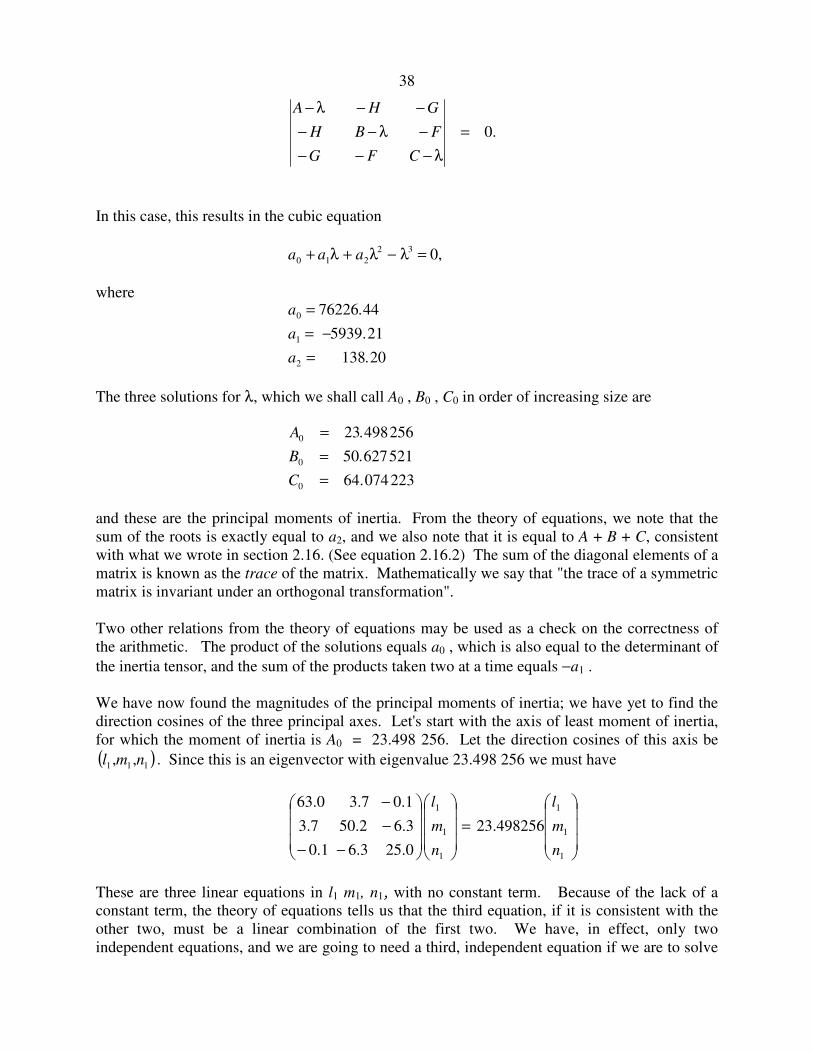
38
.0=
λ−−−
−λ−−
−−λ−
CFG
FBH
GHA
In this case, this results in the cubic equation
a a a0 1 2
2 3 0+ + − =λ λ λ ,
where a
a
a
0
1
2
76226 44
5939 21
138 20
=
= −
=
.
.
.
The three solutions for λ, which we shall call A0 , B0 , C0 in order of increasing size are
A
B
C
0
0
0
23 498256
50 627521
64 074223
=
=
=
.
.
.
and these are the principal moments of inertia. From the theory of equations, we note that the
sum of the roots is exactly equal to a2, and we also note that it is equal to A + B + C, consistent
with what we wrote in section 2.16. (See equation 2.16.2) The sum of the diagonal elements of a
matrix is known as the trace of the matrix. Mathematically we say that "the trace of a symmetric
matrix is invariant under an orthogonal transformation".
Two other relations from the theory of equations may be used as a check on the correctness of
the arithmetic. The product of the solutions equals a0 , which is also equal to the determinant of
the inertia tensor, and the sum of the products taken two at a time equals −a1 .
We have now found the magnitudes of the principal moments of inertia; we have yet to find the
direction cosines of the three principal axes. Let's start with the axis of least moment of inertia,
for which the moment of inertia is A0 = 23.498 256. Let the direction cosines of this axis be
( )111 ,, nml . Since this is an eigenvector with eigenvalue 23.498 256 we must have
=
−−
−
−
1
1
1
1
1
1
498256.23
0.253.61.0
3.62.507.3
1.07.30.63
n
m
l
n
m
l
These are three linear equations in l1 m1, n1, with no constant term. Because of the lack of a
constant term, the theory of equations tells us that the third equation, if it is consistent with the
other two, must be a linear combination of the first two. We have, in effect, only two
independent equations, and we are going to need a third, independent equation if we are to solve

39
for the three direction cosines. If we let l l n m m n' / ' /= =1 1 1 1and , then the first two equations
become
.03.6'744701.26'7.3
01.0'7.3'744501.39
=−+
=−+
ml
ml
The solutions are l
m
' .
' . .
= −
= +
0 019825485
0 238686617
The correctness of the arithmetic can and should be checked by verifying that these solutions
also satisfy the third equation.
The additional equation that we need is provided by Pythagoras's theorem, which gives for the
relation between three direction cosines
,12
1
2
1
2
1 =++ nml
or ,
1''
122
2
1++
=ml
n
whence n1 = ! 0.972495608.
Thus we have, for the direction cosines of the axis corresponding to the moment of inertia A0,
608495972.0
881121232.0
197280019.0
1
1
1
±=
±=
=
n
m
l m
(Check that l m n1
2
1
2
1
2 1+ + = . )
It does not matter which sign you choose - after all, the principal axis goes both ways.
Similar calculations for B0 yield
774094228.0
706312932.0
440652280.0
2
2
2
±=
=
±=
n
m
l
m
and for C0
40
415170047.0
987330277.0
796615959.0
3
3
3
m=
±=
±=
n
m
l
For the first two axes, it does not matter whether you choose the upper or the lower sign. For the
third axes, however, in order to ensure that the principal axes form a right-handed set, choose the
sign such that the determinant of the matrix of direction cosines is +1.
We have just seen that, if we know the moments and products of inertia A, B, C, F, G, H with
respect to some axes (i.e. if we know the elements of the inertia tensor) we can find the principal
moments of inertia A0 , B0 , C0 by diagonalizing the inertia tensor, or finding its eigenvalues. If,
on the other hand, we know the principal moments of inertia of a system of particles (or of a
solid body, which is a collection of particles), how can we find the moment of inertia I about an
axis whose direction cosines with respect to the principal axes are (l , m , n)?
First, some geometry.
Let Oxyz be a coordinate system, and let P (x , y , z ) be a point whose position vector is
r i j k= + +x y z .
Let L be a straight line passing through the origin, and let the direction cosines of this line be
(l , m , n ). A unit vector e directed along L is represented by
e i j k= + +l m n .
The angle θ between r and e is found from the scalar product r • e, given by
r cos θ = r • e.
I.e. ( ) .cos2
1222 nzmylxzyx ++=θ++
The perpendicular distance p from P to L is
( ) .sinsin 2
1222 θ++=θ= zyxrp
If we write ( ) ,cos1sin 2
12 θ−=θ we soon obtain
( ) .22222 znymxlzyxp ++−++=
Noting that ,1,1,1 222222222 mlnlnmnml −−=−−=−−= we find, after further
manipulation:

41
( ) ( ) ( ) ( ).22222222222 lmxynlzxmnyzyxnxzmzylp ++−+++++=
Now return to our collection of particles, and let Oxyz be the principal axes of the system. The
moment of inertia of the system with respect to the line L is
,2∑= MpI
where I have omitted a subscript i on each symbol. Making use of the expression for p and
noting that the product moments of the system with respect to Oxyz are all zero, we obtain
I l A m B n C= + +2
0
2
0
2
0 . 2.18.1
Also, let A, B, C, F, G, H be the moments and products of inertia with respect to a set of
nonprincipal orthogonal axes; then the moment of inertia about some other axis with direction
cosines l, m, n with respect to these nonprincipal axes is
.222222 lmHnlGmnFCnBmAlI −−−++= 2.18.2
Example. A Brick.
We saw in section 16 that the moment of inertia of a uniform solid cube of mass M and side 2a
about a body diagonal is 23
2Ma , and we saw how very easy this was. At that time the problem
of finding the moment of inertia of a uniform solid rectangular parallelepiped of sides 2a, 2b, 2c
must have seemed intractable, but by now it is not at all hard.

42
Thus we have:
( )( )( )
( )
( )
( ).
2
1
2
1
2
1
222
222
222
22
31
0
22
31
0
22
31
0
cba
cn
cba
bm
cba
al
baMC
acMB
cbMA
++=
++=
++=
+=
+=
+=
We obtain: ( )
( ).
3
2222
222222
cba
baaccbMI
++
++=
We note:
i. This is dimensionally correct;
ii. It is symmetric in a, b, c;
iii. If a = b = c, it reduces to 23
2Ma .
2.19 Moment of Inertia with Respect to a Point.
By “moment of inertia” we have hitherto meant the second moment of mass with respect to an
axis. We were easily able to identify it with the rotational inertia with respect to the axis,
namely the ratio of an applied torque to the resulting angular acceleration.
I am now going to define the (second) moment of inertia with respect to a point, which I shall
take unless otherwise specified to mean the origin of coordinates. If we have a collection of
mass points mi at distances ri from the origin, I define
( )2222
iiii
iii
i zyxmrm ++∑=∑=I 2.19.1
as the (second) moment of inertia with respect to the origin, also sometimes called the
“geometric moment of inertia”. I cannot relate it in an obvious way to a simple dynamical
concept in the same way that I related moment of inertia with respect to an axis to rotational
inertia, but we shall see that it is by no means merely a tedious exercise in arithmetic, and it does
have its uses. The symbol I has probably been used rather a lot in this chapter; so to describe the
geometric moment of inertia I am going to use the symbol I.
43
The moment of inertia with respect to the origin is clearly something that does not depend on the
orientation of any particular basis set of orthogonal axes, since it depends only on the distances
of the particles from the origin.
If you recall the definitions of A, B and C from section 2.15, you will easily see that
( ).21 CBA ++=I 2.19.2
and we already noted (see equation 2.16.2) that CBA ++ is invariant under rotation of axes. In
section 2.18 we expressed it slightly more generally by saying "the trace of a symmetric matrix is
invariant under an orthogonal transformation". By now it probably seems slightly less
mysterious.
Let us now calculate the geometric moment of inertia of a uniform solid sphere of radius a, mass
m, density ρ, with respect to the centre of the sphere. It is
.2dmrsphere
∫=I 2.19.3
The element of mass, dm, here is the mass of a shell of radii r, r + dr; that is 4πρr2dr. Thus
.4 5
54
0
4 adrra
πρ=∫πρ=I 2.19.4
With ,3
34 ρπ= am this becomes
.2
53 ma=I 2.19.5
Indeed, for any spherically symmetric distribution of matter, since A = B = C, it will be clear
from equation 2.19.2, that the moment of inertia with respect to the centre is 3/2 times the
moment of inertia with respect to an axis through the centre. For example, it is obvious from the
definition of moment of inertia with respect to the centre that for a hollow spherical shell it is just
ma2, and therefore the moment of inertia with respect to an axis through the centre is .2
32 ma In
other words, you can work out that the moment of inertia of a hollow spherical shell with respect
to an axis through its centre is 2
32 ma in your head without any of the integration that we did in
section 2.7!
By way of illustration, consider three spheres, each of radius a and mass M, but the density
between centre and surface varies as
2
2
02
2
00 1,1,1a
kr
a
kr
a
kr−ρ=ρ
−ρ=ρ
−ρ=ρ

44
for the three spheres. Calculate for each the moment of inertia about an axis through the centre
of the sphere. Express the answer in the form ).(2
52 kfMa ×
Solution. The mass of a sphere is
drrrMa
∫ ρπ=0
2)(4
and so .)(5
8
0
22
2
52 drrr
aMa
a
∫ ρπ
=
The moment of inertia about the centre is
drrra
∫ ρπ=0
4)(4I
and so the moment of inertia about an axis through the centre is
.)(3
8
0
4drrrI
a
∫ ρπ
=
Therefore .
)(
)(
3
5
0
2
0
4
22
52
∫
∫ρ
ρ=
a
a
drrr
drrr
aMa
I
For the first two spheres the integrations are straightforward. I make it
k
k
Ma
I
912
10122
52 −
−=
for the first sphere, and
k
k
Ma
I
2135
25352
52 −
−=
for the second sphere. The integrations for the third sphere need a little more patience, but I
make the answer
,)4sin4(sin18
)6sin4sin32sin312(522
52 α−αα
α+α−α−α=
Ma
I
where .sin k=α

45
This should be enough to convince that the concept of I is useful – but it is not its only use. We
shall meet it again in Chapter 3 on the dynamics of systems of particles; in particular, it will play
a role in what we shall become familiar with as the virial theorem.
2.20 Ellipses and Ellipsoids
Here are some problems concerning ellipses and ellipsoids that might be of interest.
Determine the principal moments of inertia of the following:
1. A uniform plane lamina of mass m in the form of an ellipse of semi axes a and b.
2. A uniform plane ring of mass m in the form of an ellipse of semi axes a and b.
3. A uniform solid triaxial ellipsoid of mass m and semi axes a, b and c.
4. A uniform hollow triaxial ellipsoid of mass m and semi axes a, b and c.
1. By integration, an elliptical lamina is slightly difficult, but by physical insight it is very easy!
The distribution of mass around the minor axis is the same as for a circular lamina of radius a,
and therefore the moment B is the same as for the circular lamina, namely 2
41 maB = . Similarly,
2
41 mbA = , and hence, by the perpendicular axes theorem, )( 22
41 bamC += .
I think you will find that the shape of the momental ellipse is the same as the shape of the
original elliptical lamina.
2. An elliptical ring (hoop) is remarkably difficult. It cannot be expressed in terms of
elementary functions, and it has to be calculated numerically. It can be expressed in terms of
elliptic integrals (no surprise there), but most of us aren’t sure what elliptic integrals are and they
hardly count as elementary functions, and they have to be calculated numerically anyway. We
take the ellipse to be .with,12
2
2
2
abb
y
a
x≤=+
Even calculating the circumference of an ellipse isn’t all that easy. The circumference is
( ) dxdsa
dx
dy∫ ∫
+=
0
2/12
14 , with .1
2/1
2
2
−=
a
xby
After a bit of algebra, this can be written as
∫ −
−adx
xa
xc
c
a
0 22
224, where
22
42
ba
ac
−= .
46
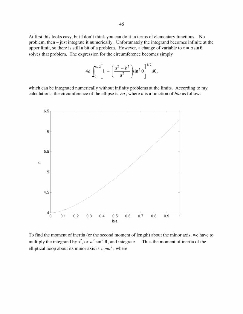
At first this looks easy, but I don’t think you can do it in terms of elementary functions. No
problem, then – just integrate it numerically. Unfortunately the integrand becomes infinite at the
upper limit, so there is still a bit of a problem. However, a change of variable to θ= sinax
solves that problem. The expression for the circumference becomes simply
θ
θ
−−
π
∫ da
baa
2/1
2
2
222/
0
sin14 ,
which can be integrated numerically without infinity problems at the limits. According to my
calculations, the circumference of the ellipse is ha , where h is a function of b/a as follows:
0 0.1 0.2 0.3 0.4 0.5 0.6 0.7 0.8 0.9 14
4.5
5
5.5
6
6.5
b/a
h
To find the moment of inertia (or the second moment of length) about the minor axis, we have to
multiply the integrand by x2, or θ22 sina , and integrate. Thus the moment of inertia of the
elliptical hoop about its minor axis is 21mac , where
47
.
sin1
sinsin1
2/1
2
2
222/
0
2
2/1
2
2
222/
0
1
θ
θ
−−
θθ
θ
−−
=π
π
∫
∫d
a
ba
da
ba
c
The moment of inertia about the major axis is 22mac , where
.
sin1
sincos1
2/1
2
2
222/
0
2
2/1
2
2
222/
02
2
2
θ
θ
−−
θθ
θ
−−
=π
π
∫
∫d
a
ba
da
ba
a
b
c
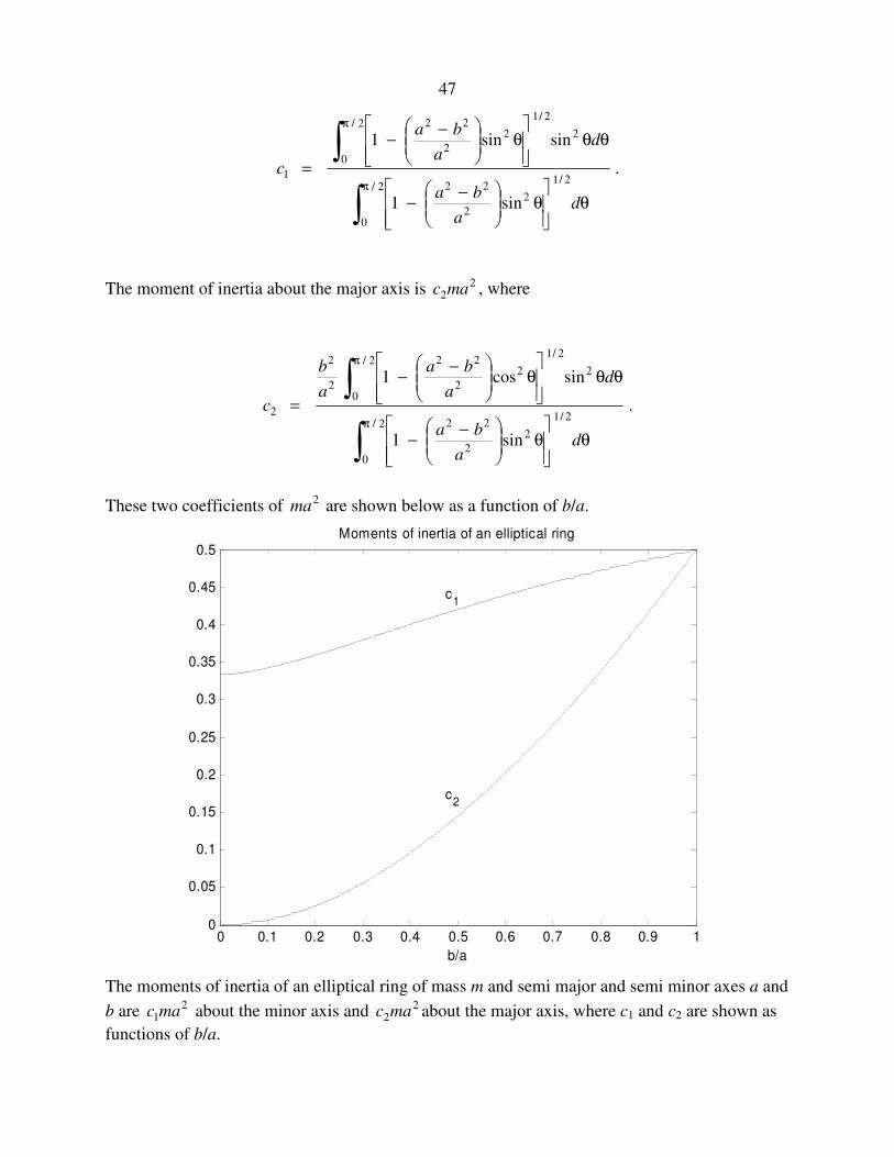
These two coefficients of 2ma are shown below as a function of b/a.
0 0.1 0.2 0.3 0.4 0.5 0.6 0.7 0.8 0.9 10
0.05
0.1
0.15
0.2
0.25
0.3
0.35
0.4
0.45
0.5Moments of inertia of an elliptical ring
b/a
c1
c2
The moments of inertia of an elliptical ring of mass m and semi major and semi minor axes a and
b are 21mac about the minor axis and 2
2mac about the major axis, where c1 and c2 are shown as
functions of b/a.

48
The moment of inertia about the major axis can also be conveniently expressed in terms of b
rather than a. If we write the moment of inertia about the major axis as 24mbc , then c4 as a
function of b/a is shown below.
0 0.1 0.2 0.3 0.4 0.5 0.6 0.7 0.8 0.9 10.5
0.52
0.54
0.56
0.58
0.6
0.62
0.64
0.66
0.68
0.7Moment of inertia of an elliptical ring
b/a
c4
The moment of inertia of an elliptical ring of mass m and semi major and semi minor axes a and b is
24mbc about the major axis, where c4 is shown as a function of b/a.
The moment of inertia about an axis perpendicular to the plane of the ellipse and passing
through its centre is 23mac , where, of course (by the perpendicular axes theorem), .213 ccc +=
It is also equal to .24
21 mbcmac +
3. For a uniform solid triaxial ellipsoid, the moments of inertia are
)()()( 22
5122
5122
51 bamCacmBcbmA +=+=+=
The momental ellipsoid is not of the same shape. Its axes are in the ratio
.::122
22
22
22
ba
cb
ac
cb
+
+
+
+
49
For example, if the axial ratios of the original ellipsoid are 1 : 2 : 3, the axial ratios of the
corresponding momental ellipsoid is ,612.1:140.1:1::15
131013 = which is slightly more
spherical than the original ellipsoid.
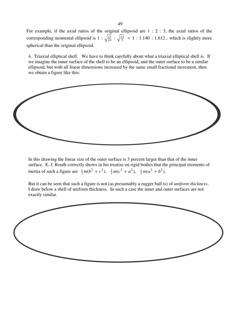
4. Triaxial elliptical shell. We have to think carefully about what a triaxial elliptical shell is. If
we imagine the inner surface of the shell to be an ellipsoid, and the outer surface to be a similar
ellipsoid, but with all linear dimensions increased by the same small fractional increment, then
we obtain a figure like this:
In this drawing the linear size of the outer surface is 3 percent larger than that of the inner
surface. E. J. Routh correctly shows in his treatise on rigid bodies that the principal moments of
inertia of such a figure are ).(),(),( 22
3122
3122
31 bamacmcbm +++
But it can be seen that such a figure is not (as presumably a rugger ball is) of uniform thickness.
I draw below a shell of uniform thickness. In such a case the inner and outer surfaces are not
exactly similar.
50
In attempting to calculate the moment of inertia of such a figure I shall restrict myself to the case
of a spheroidal shell of uniform thickness. That is to say, an ellipsoid with two equal axes,
represented by the equation, in cylindrical coordinates
,12
2
2
2
=+ρ
c
z
a
where .222 yx +=ρ Further, if I put ,ac χ= the equation to the spheroid can be written
.2
2
22
az
=χ
+ρ
If 1<χ , the spheroid is oblate. If 1>χ , the spheroid is prolate.
We’ll first need to calculate its surface area, which is
.14
2/12
0dz
dz
dA
c
ρ+ρπ= ∫
After some algebra, this comes to
),(4 2 χπ= faA
where 1for111
ln1
)(
2
2
2
21 ≤χ
+
χ
χ−+
χ−
χ=χf
and .1for11
sin1
)(
21
2
2
21 ≥χ
+
χ
−χ
−χ
χ=χ −
f
This function is shown below as far as χ = 2. For χ = 0, the figure is a disc whose total area
(upper and lower surface) is ,2 2aπ and .21=f For χ = 1, the figure is a sphere whose area is
,4 2aπ and .1=f The function goes to infinity as χ goes to infinity.

51
0 0.2 0.4 0.6 0.8 1 1.2 1.4 1.6 1.8 2
0.6
0.8
1
1.2
1.4
1.6
Surface area of a spheroid
Axial ratio χ = c/a
f(χ
)
Oblate Prolate
The moment of inertia about the z-axis is
.14
2/12
3
0dz
dz
d
A
mI
c
ρ+ρ
π= ∫
After some algebra this becomes
),(2 χ= gmaI
( )
( )1for
11ln)1()1(4
11ln)1)(2(
1)(
/
/2222/32
2422
≤χ
χχ−+χ−χ+χ−
χχ−+χ−χ−χ−
−=χg
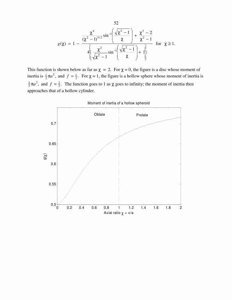
52
.1for
11
sin1
4
1
21sin
)1(1)(
21
2
2
2
221
2/32
4
≥χ
+
χ
−χ
−χ
χ
−χ
−χ+
χ
−χ
−χ
χ
−=χ
−
−
g
This function is shown below as far as χ = 2. For χ = 0, the figure is a disc whose moment of
inertia is ,2
21 aπ and .
21=f For χ = 1, the figure is a hollow sphere whose moment of inertia is
,2
32 aπ and .
32=f The function goes to 1 as χ goes to infinity; the moment of inertia then
approaches that of a hollow cylinder.
0 0.2 0.4 0.6 0.8 1 1.2 1.4 1.6 1.8 20.5
0.55
0.6
0.65
0.7
Moment of inertia of a hollow spheroid
Axial ratio χ = c/a
g( χ
)
Oblate Prolate

53
2.21 Tetrahedra
Exercise. Show that the moment of inertia about an axis through the centre of mass of a uniform
solid regular tetrahedron of mass m and edge length a is .2
201 ma
Exercise. Show that the moment of inertia of a methane molecule about an axis through the
carbon atom is ,2
38 ml where l is the bond length and m is the mass of a hydrogen atom.
And, in case you are wondering that I haven’t specified the orientation of the axis in either case,
the solid regular tetrahedron and the methane molecule are both spherical tops, and the moment of
inertia is the same about any axis through the centre of mass.