Embed Size (px)
Citation preview

Joint Interoperability Test Command (JTE) 17 Jan 12
MEMORANDUM FOR DISTRIBUTION
SUBJECT: Special Interoperability Test Certification of the Cambium Networks Point To Point
(PTP) 600 Series with Software Version 10-00
References: (a) DOD Directive 4630.05, “Interoperability and Supportability of Information
Technology (IT) and National Security Systems (NSS),” 5 May 2004
(b) CJCSI 6212.01E, “Interoperability and Supportability of Information
Technology and National Security Systems,” 15 December 2008
(c) through (e), see Enclosure 1
1. References (a) and (b) establish the Defense Information Systems Agency (DISA), Joint
Interoperability Test Command (JITC), as the responsible organization for interoperability (IO)
test certification.
2. The Cambium Networks PTP 600 Series with software version 10-00 are hereinafter referred to
as the system under test (SUT). The SUT meets all of its critical interoperability requirements and
is certified for joint use within the Defense Information System Network (DISN) as a Fixed
Network Element. The SUT meets the critical interoperability requirements set forth in Reference
(c), using test procedures derived from Reference (d). The SUT was tested with the PTP 45600
Outdoor Unit (ODU). The PTP 48600, PTP 25600, PTP 49600, PTP 54600, PTP 58600, PTP
59600 ODUs were not tested; however they employ the same software and similar hardware as the
SUT. JITC analysis determined these components to be functionally identical to the SUT for
interoperability certification purposes and they are also certified for joint use. No other
configurations, features, or functions, except those cited within this report, are certified by JITC.
This certification expires upon changes that affect interoperability, but no later than three years
from the date of the Unified Capability (UC) Approved Products List (APL) memorandum.
3. This finding is based on interoperability testing and DISA Certifying Authority (CA)
recommendation. IO testing was conducted by the U.S. Army Information Systems Engineering
Command Technology Integration Center (USAISEC TIC), Fort Huachuca Arizona, from 14
through 17 September 2011 on the Motorola PTP 600. On 17 October 2011, Motorola and
Cambium Networks issued a letter of sameness establishing that both companies’ PTP 600
Series products are functionally identical and therefore this certification applies to the PTP 600
Series products manufactured by both companies. The DISA CA provided a positive
recommendation on 14 December 2011 based on the security testing completed by DISA-led
Information Assurance (IA) test teams and published in a separate report, Reference (e). The
IN REPLY REFER TO:
DEFENSE INFORMATION SYSTEMS AGENCY P. O. BOX 549
FORT MEADE, MARYLAND 20755-0549

JITC, Memo, JTE, Special Interoperability Test Certification of the Cambium Networks Point To
Point (PTP) 600 Series with Software Version 10-00
2
Certification Testing Summary (Enclosure 2) documents the test results and describes the test
network.
4. The overall IO status of the SUT is indicated in Table 1. The interfaces and associated
Capability Requirements (CRs) and Feature Requirements (FRs) used to evaluate the IO statuses
are listed in Table 2. The IO test status is based on the SUT’s ability to meet:
a. Defense Switched Network (DSN) services for Network and Applications specified in
Reference (c).
b. The overall system IO performance derived from test procedures listed in Reference (d).
Table 1. SUT Interoperability Test Summary
DSN Access Interfaces
Interface & Signaling Critical Status Remarks T1 PRI (ANSI T1.607/ANSI T1.619a) No1 Not Tested Not Available E1 PRI (ITU-T Q.931/ ITU-T Q.955.3) No1 Not Tested Not Available
T1 CAS (DTMF/MFR1/DP) No1 Not Tested Not Available E1 CAS (DTMF/MFR1/DP) No1 Not Tested Not Available
ITU-T V.35, ITU-T V.36, ITU-T V.37 No1 Not Tested Not Available T1 SS7 (ANSI T1.619a) No1 Not Tested Not Available E1 SS7 (ANSI T1.619a) No1 Not Tested Not Available
EIA-232 No1 Not Tested Not Available EIA-530 No1 Not Tested Not Available
ITU-T X.21 No1 Not Tested Not Available FXS (2-Wire Analog) No1 Not Tested Not Available FXO (2-Wire Analog) No1 Not Tested Not Available
E&M (Type I, II, III, IV) No1 Not Tested Not Available Copper Media (1000 Mbps Ethernet) No1 Partial Compliance See note 2.
DSN Transport Interfaces
Transport Level Critical Status Remarks Proprietary Adaptive Modulation Wireless (5.4, 5.8,
and 5.9 GHz License Exempt RF band, and 2.5, 4.5,4.8,
and 4.9 licensed RF band)
No Certified Proprietary Interface
Features And Capabilities
Features And Capabilities Critical Status Remarks Synchronization Yes Certified Met all CRs and FRs.
Network Management Yes Certified Met all CRs and FRs.
Voice Compression No Not Certified Voice compression is not supported by the SUT.
Security Yes Certified See note 3.
NOTES: 1 The UCR does not stipulate a minimum access interface requirement for a Fixed Network Element.
2 The SUT supports the access interface at the 1000 Mbps FDX Ethernet constrained to a maximum throughput of the wireless transport, 300
Mbps. The SUT supports full rate operations in 10/100 Mbps FDX Ethernet for access interfaces.
3 Information assurance testing is accomplished via DISA-led Information Assurance test teams and published in a separate report, Reference (e).

JITC, Memo, JTE, Special Interoperability Test Certification of the Cambium Networks Point To
Point (PTP) 600 Series with Software Version 10-00
3
Table 1. SUT Interoperability Test Summary (continued)
LEGEND: ANSI American National Standards Institute
CAS Channel Associated Signaling
CRs Capability Requirements
DCE Data Circuit-Terminating Equipment
DISA Defense Information Systems Agency
DP Dial Pulse
DSN Defense Switched Network
DSS1 Digital Subscriber Signaling 1
DTE Data Terminal Equipment
DTMF Dual Tone Multi-Frequency
E&M Ear and Mouth
E1 European Basic Multiplex Rate (2.048 Mbps)
EIA Electronic Industries Alliance
EIA-232 Standard for defining the mechanical and electrical
characteristics for connecting DTE and DCE data
communications devices
EIA-530 Standard for 25-position interface for data terminal
equipment and data circuit-terminating equipment
employing serial binary data interchange
FDX Full Duplex
FRs Feature Requirements
ISDN Integrated Services Digital Network
ITU-T International Telecommunication Union -
Telecommunication Standardization Sector
FXO Foreign Exchange Office
FXS Foreign Exchange Station
GHz gigahertz
kbps kilobits per second
kHz kiloHertz
Mbps Megabits per second
MFR1 Multi-Frequency Recommendation 1
MLPP Multi-Level Precedence and Preemption
PRI Primary Rate Interface
Q.931 Signaling Standard for ISDN
Q.955.3 ISDN Signaling standard for E1 MLPP
RF radio frequency
SS7 Signaling System 7
SUT System Under Test
T1 Digital Transmission Link Level 1 (1.544 Mbps)
T1.607 ISDN – Layer 3 Signaling Specification for Circuit Switched
Bearer Service for DSS1
T1.619a SS7 and ISDN MLPP Signaling Standard for T1
UCR Unified Capabilities Requirements
V.35 Standard for data transmission at 48 kbps using 60-108 kHz
group band circuits
V.36 Modems for synchronous data transmission using 60-108 kHz
group band circuits
V.37 Synchronous data transmission at a data signaling rate higher
than 72 kbps using 60-108 kHz group band circuits
X.21 includes specifications for DTE/DCE physical interface
elements, alignment of call control characters and error
checking, elements of the call control phase for circuit
switching services, and test loops

JITC, Memo, JTE, Special Interoperability Test Certification of the Cambium Networks Point To
Point (PTP) 600 Series with Software Version 10-00
4
Table 2. SUT Capability and Feature Interoperability Requirements
DSN Access Interfaces
Interface Critical Requirements
Required or Conditional References
T1 PRI
(ANSI T1.607/ANSI
T1.619a)
T1 CAS
(DTMF/MFR1/DP)
T1 SS7 (ANSI T1.619a)
No1
No1
No1
• DS1 Interface Characteristics (C) as specified in UCR
2008, Section 5.2.6.1
• DS1 Supervisory Channel Associated Signaling (C) as
specified in UCR 2008, Section 5.2.6.1
• DS1 Clear Channel Capability (C) as specified in UCR
2008, Section 5.2.6.1 (SS7 and PRI only)
• DS1 Alarm and Restoral Requirements (C) as specified in
UCR 2008, Section 5.2.6.1
• MOS (R)
• BERT (R)
• Secure Transmission (Voice and Data) (R) as specified in
UCR 2008, Section 5.2.12.6
• Modem (R)
• Facsimile (R)
• Call Control Signals (R)
• Alarms (R) as specified in UCR 2008, Section 5.2.1.5.7
• Call Congestion Control (R)
• Call Congestion for TDM Transport (C)
• Voice Compression (C)
• UCR Section 5.9.2.3.4
• UCR Section 5.9.2.3.4
• UCR Section 5.9.2.3.4
• UCR Section 5.9.2.3.4
• UCR Section 5.9.2.1
• UCR Section 5.9.2.1
• UCR Section 5.9.2.1
• UCR Section 5.9.2.1
• UCR Section 5.9.2.1
• UCR Section 5.9.2.1
• UCR Section 5.9.2.1.1
• UCR Section 5.9.2.1.2
• UCR Section 5.9.2.1.2.1
• UCR Section 5.9.2.2
E1 PRI (ITU-T Q.931/
ITU-T Q.955.3)
E1 CAS
(DTMF/MFR1/DP)
E1 SS7 (ANSI T1.619a)
No1
No1
No1
• E1 Interface Characteristics (C) as specified in UCR
2008, Section 5.2.6.2
• E1 Supervisory Channel Associated Signaling (C) as
specified in UCR 2008, Section 5.2.6.2
• E1 Clear Channel Capability (C) as specified in UCR
2008, Section 5.2.6.2
• E1 Alarm and Restoral Requirements (C) as specified in
UCR 2008, Section 5.2.6.2
• MOS (R)
• BERT (R)
• Secure Transmission (Voice and Data) (R) as specified in
UCR 2008, Section 5.2.12.6
• Modem (R)
• Facsimile (R)
• Call Control Signals (R)
• Alarms (R) as specified in UCR 2008, Section 5.2.1.5.7
• Call Congestion Control (R)
• Call Congestion for TDM Transport (C)
• Voice Compression (C)
• UCR Section 5.9.2.3.5
• UCR Section 5.9.2.3.5
• UCR Section 5.9.2.3.5
• UCR Section 5.9.2.3.5
• UCR Section 5.9.2.1
• UCR Section 5.9.2.1
• UCR Section 5.9.2.1
• UCR Section 5.9.3.1
• UCR Section 5.9.2.1
• UCR Section 5.9.2.1
• UCR Section 5.9.2.1.1
• UCR Section 5.9.2.1.2
• UCR Section 5.9.2.1.2.1
• UCR Section 5.9.2.2
ITU-T V.35, ITU-T
V.36, ITU-T V.37
EIA-232, EIA-530,
ITU-T X.21,
No1
• Serial Interface Characteristics (C) as specified in UCR
2008, Section 5.2.6.4
• BERT (R)
• UCR Section 5.9.2.3.2
• UCR Section 5.9.2.1
E&M (Type I, II, III,
IV), FXS and FXO
(2-wire Analog)
No1
• Analog 2 Wire and 4 Wire Interface Characteristics (C)
as specified in UCR 2008, Section 5.2.6.4
• MOS (R)
• BERT (R)
• Secure Transmission (Voice and Data) (R) as specified in
UCR 2008, Section 5.2.12.6
• Modem (R)
• Facsimile (R)
• Call Control Signals (R)
• Alarms (R) as specified in UCR 2008, Section 5.2.1.5.7
• Call Congestion Control (R)
• Call Congestion for TDM Transport (C)
• Voice Compression (C)
• UCR Section 5.9.2.3.1
• UCR Section 5.9.2.1
• UCR Section 5.9.2.1
• UCR Section 5.9.2.1
• UCR Section 5.9.2.1
• UCR Section 5.9.2.1
• UCR Section 5.9.2.1
• UCR Section 5.9.2.1.1
• UCR Section 5.9.2.1.2
• UCR Section 5.9.2.1.2.1
• UCR Section 5.9.2.2

JITC, Memo, JTE, Special Interoperability Test Certification of the Cambium Networks Point To
Point (PTP) 600 Series with Software Version 10-00
5
Table 2. SUT Capability and Feature Interoperability Requirements (continued)
DSN Transport Interfaces
Interface Critical Requirements
Required or Conditional References
Multi-Mode or Single
Mode Fiber (1.3 Gigabit) No2
• MOS (R)
• BERT (R)
• Secure Transmission (Voice and Data) (R) as specified
in UCR 2008, Section 5.2.12.6
• Modem (R)
• Facsimile (R)
• Call Control Signals (includes MLPP) (R)
• Congestion Control (C) (IP interface only)
• Voice Compression (C)
• Alarms
• Delay (R)
• UCR Section 5.9.2.1
• UCR Section 5.9.2.1
• UCR Section 5.9.2.1
• UCR Section 5.9.2.1
• UCR Section 5.9.2.1
• UCR Section 5.9.3.7
• UCR Section 5.9.2.1.2.1
• UCR Section 5.9.2.2
• UCR Section 5.9.2.1.1
• UCR Section 5.9.2.1.2
Twisted Pair
Copper (1.3 Gigabit) No2
• MOS (R)
• BERT (R)
• Secure Transmission (Voice and Data) (R) as specified
in UCR 2008, Section 5.2.12.6
• Modem (R)
• Facsimile (R)
• Call Control Signals (includes MLPP) (R)
• Congestion Control (C) (IP interface only)
• Voice Compression (C)
• Alarms
• Delay (R)
• UCR Section 5.9.2.1
• UCR Section 5.9.2.1
• UCR Section 5.9.2.1
• UCR Section 5.9.2.1
• UCR Section 5.9.2.1
• UCR Section 5.9.3.7
• UCR Section 5.9.2.1.2.1
• UCR Section 5.9.2.2
• UCR Section 5.9.2.1.1
• UCR Section 5.9.2.1.2
SUT Features And Capabilities
Feature/Capability Critical Requirements
Required or Conditional References
Compression No • Voice Compression standards • UCR Section 5.9.2.2
Synchronization Yes • Timing (R) as specified in UCR 2008, Section 5.2.10.1 • UCR Section 5.9.2.3.7
Network Management Yes
• Management Option (R)
Local Management (Front Panel and/or External
Console) (C)
ADIMSS (C) as specified in UCR 2008, sections 5.2.8,
Network Management, 5.2.8.3, Fault Management, and
5.2.8.4, Configuration Management.
• Fault Management (C)
• Loop Back Capability (C)
• Operational Configuration Restoral (R)
• UCR Section 5.9.2.4.1
• UCR Section 5.9.2.4.2
• UCR Section 5.9.2.4.3
• UCR Section 5.9.2.4.4
Security Yes • STIGs and DoDI 8510.01 (DIACAP) (R) • UCR Section 5.9.2.6
NOTES:
1 The UCR does not stipulate a minimum required DSN access interface.
2 The UCR does not stipulate a minimum required DSN transport interface.

JITC, Memo, JTE, Special Interoperability Test Certification of the Cambium Networks Point To
Point (PTP) 600 Series with Software Version 10-00
6
Table 2. SUT Capability and Feature Interoperability Requirements (continued)
LEGEND: ADIMSS Advanced DSN Integrated Management Support
System
ANSI American National Standards Institute
BERT Bit Error Rate Test
C Conditional
CAS Channel Associated Signaling
DCE Data Circuit-Terminating Equipment
DIACAP Department of Defense Information Assurance
Certification and Accreditation Process
DoDI Department of Defense Instruction
DP Dial Pulse
DS1 Digital Signal Level 1
DSN Defense Switched Network
DSS1 Digital Subscriber Signaling 1
DTE Data Terminal Equipment
DTMF Dual Tone Multi-Frequency
E&M Ear and Mouth
E1 European Basic Multiplex Rate (2.048 Mbps)
EIA-232 Standard for defining the mechanical and electrical
characteristics for connecting DTE and DCE data
communications devices
EIA-530 Standard for 25-position interface for data terminal
equipment and data circuit-terminating equipment
employing serial binary data interchange
FXO Foreign Exchange Office
FXS Foreign Exchange Station
ISDN Integrated Services Digital Network
ITU-T International Telecommunication Union -
Telecommunication Standardization Sector
kbps kilobits per second
kHz kiloHertz
Mbps Megabits per second
MFR1 Multi-Frequency Recommendation 1
MLPP Multi-Level Precedence and Preemption
MOS Mean Opinion Score
PRI Primary Rate Interface
Q.931 Signaling Standard for ISDN
Q.955.3 ISDN Signaling standard for E1 MLPP
R Required
SS7 Signaling System 7
STIGs Security Technical Implementation Guides
SUT System Under Test
T1 Digital Transmission Link Level 1 (1.544 Mbps)
T1.607 ISDN – Layer 3 Signaling Specification for Circuit Switched
Bearer Service for DSS1
T1.619a SS7 and ISDN MLPP Signaling Standard for T1
TDM Time Division Multiplexing
UCR Unified Capabilities Requirements
V.35 Standard for data transmission at 48 kbps using 60-108 kHz
group band circuits
V.36 Modems for synchronous data transmission using 60-108
kHz group band circuits
V.37 Synchronous data transmission at a data signaling rate higher
than 72 kbps using 60-108 kHz group band circuits
X.21 includes specifications for DTE/DCE physical interface
elements, alignment of call control characters and error
checking, elements of the call control phase for circuit
switching services, and test loops
5. No detailed test report was developed in accordance with the Program Manager’s request.
JITC distributes interoperability information via the JITC Electronic Report Distribution (ERD)
system, which uses Unclassified-But-Sensitive Internet Protocol Router Network (NIPRNet) e-
mail. More comprehensive interoperability status information is available via the JITC System
Tracking Program (STP). The STP is accessible by .mil/gov users on the NIPRNet at
https://stp.fhu.disa.mil. Test reports, lessons learned, and related testing documents and
references are on the JITC Joint Interoperability Tool (JIT) at http://jit.fhu.disa.mil (NIPRNet).
Information related to DSN testing is on the Telecom Switched Services Interoperability (TSSI)
website at http://jitc.fhu.disa.mil/tssi. Due to the sensitivity of the information, the Information
Assurance Accreditation Package (IAAP) that contains the approved configuration and
deployment guide must be requested directly through government civilian or uniformed military
personnel from the Unified Capabilities Certification Office (UCCO), e-mail: [email protected].
JITC, Memo, JTE, Special Interoperability Test Certification of the Cambium Networks Point To
Point (PTP) 600 Series with Software Version 10-00
7
6. The JITC point of contact is Captain Stéphane Arsenault, DSN 879-5269, commercial (520)
538-5269, FAX DSN 879-4347, or e-mail to [email protected]. The JITC’s mailing
address is P.O. Box 12798, Fort Huachuca, AZ 85670-2798. The tracking number for the SUT
is 1127301.
FOR THE COMMANDER:
2 Enclosures a/s
for BRADLEY A. CLARK
Chief
Battlespace Communications Portfolio
Distribution (electronic mail):
Joint Staff J-6
Joint Interoperability Test Command, Liaison, TE3/JT1
Office of Chief of Naval Operations, CNO N6F2
Headquarters U.S. Air Force, Office of Warfighting Integration & CIO, AF/XCIN (A6N)
Department of the Army, Office of the Secretary of the Army, DA-OSA CIO/G-6 ASA (ALT),
SAIS-IOQ
U.S. Marine Corps MARCORSYSCOM, SIAT, MJI Division I
DOT&E, Net-Centric Systems and Naval Warfare
U.S. Coast Guard, CG-64
Defense Intelligence Agency
National Security Agency, DT
Defense Information Systems Agency, TEMC
Office of Assistant Secretary of Defense (NII)/DOD CIO
U.S. Joint Forces Command, Net-Centric Integration, Communication, and Capabilities
Division, J68
Defense Information Systems Agency, GS23
Enclosure 1
ADDITIONAL REFERENCES
(c) Office of the Assistant Secretary of Defense, “Department of Defense Unified
Capabilities Requirements 2008 Change 2,” December 2010
(d) Joint Interoperability Test Command, “Defense Switched Network Generic Switch Test
Plan (GSTP), Change 2,” 2 October 2006
(e) Joint Interoperability Test Command, “Information Assurance (IA) Assessment of
Motorola PTP 600 (Tracking Number 1190601),” September 2011

1-1
This page intentionally left blank.
Enclosure 2
CERTIFICATION TESTING SUMMARY
1. SYSTEM TITLE. The Cambium Networks Point To Point (PTP) 600 Series Software Version 10-00 (Tracking Number: 1127301); hereinafter referred to as the SUT.
2. PROPONENT. Defense Information System Agency (DISA). 3. PROGRAM MANAGER. Mr. Jessie L. Showers, NS2, Room 5W19, P.O. Box 4502, Arlington, VA 22204-4502, e-mail: [email protected] 4. SPONSOR. Installation Information Infrastructure Modernization Program, Sponsor POC: Mr. Steven Pursell, U.S. Army Information Systems Engineering Command, Technology Integration Center (USAISEC TIC), Bldg 53302, Fort Huachuca, AZ 85613, e-mail: [email protected] 5. TESTER. USAISEC TIC, Bldg 53302, Fort Huachuca, AZ, 85613-5300 6. SYSTEM UNDER TEST DESCRIPTION. Cambium Networks PTP 600 is a Point-to-Point (PTP) bridge that supports a variety of fixed and portable communications devices over a high availability wireless Ethernet bridge. The Cambium Networks PTP operates in the 4.4 to 4.8 GigaHertz (GHz) spectrum (PTP 45600 and 48600) at data rates up to 300 Megabits per second (Mbps) for the 45600 and 200 Mbps for the 48600 and the 5.4 - 5.8 GHz spectrum (PTP 54600 and 58600) at data rates up to 300 Mbps. The over the air interface uses a proprietary protocol, which utilizes Advanced Encryption Standard (AES) encryption for securing communications. The PTP 600 series has a connectorized model for use with external antennas and an integrated model with a built-in antenna. All PTP 600 frequency variants and connector/integrated variants use the same software. 7. OPERATIONAL ARCHITECTURE. The Unified Capabilities Requirements (UCR) Network Element (NE) diagram is depicted in Figure 2-1. This figure depicts the relationship of the SUT, an NE in the operational architecture.

2-2
Figure 2-1. Network Elements Diagram

2-3
8. REQUIRED SYSTEM INTERFACES. The SUT Interoperability Test Summary is shown in Table 2-1 and the Capability and Feature Requirements used to evaluate the interoperability of the SUT are indicated in Table 2-2. The SUT met these requirements through testing.
Table 2-1. SUT Interoperability Test Summary
DSN Access Interfaces
Interface & Signaling Critical Status Remarks T1 PRI (ANSI T1.607/ANSI T1.619a) No1 Not Tested Not Available E1 PRI (ITU-T Q.931/ ITU-T Q.955.3) No1 Not Tested Not Available
T1 CAS (DTMF/MFR1/DP) No1 Not Tested Not Available E1 CAS (DTMF/MFR1/DP) No1 Not Tested Not Available
ITU-T V.35, ITU-T V.36, ITU-T V.37 No1 Not Tested Not Available T1 SS7 (ANSI T1.619a) No1 Not Tested Not Available E1 SS7 (ANSI T1.619a) No1 Not Tested Not Available
EIA-232 No1 Not Tested Not Available EIA-530 No1 Not Tested Not Available
ITU-T X.21 No1 Not Tested Not Available FXS (2-Wire Analog) No1 Not Tested Not Available FXO (2-Wire Analog) No1 Not Tested Not Available
E&M (Type I, II, III, IV) No1 Not Tested Not Available Copper Media (1000 Mbps Ethernet) No1 Partial Compliance See note 2.
DSN Transport Interfaces
Transport Level Critical Status Remarks Proprietary Adaptive Modulation Wireless (5.4, 5.8,
and 5.9 GHz License Exempt RF band, and 2.5, 4.5,4.8,
and 4.9 licensed RF band)
No Certified Proprietary Interface
Features And Capabilities
Features And Capabilities Critical Status Remarks Synchronization Yes Certified Met all CRs and FRs.
Network Management Yes Certified Met all CRs and FRs.
Voice Compression No Not Certified Voice compression is not supported by the SUT.
Security Yes Certified See note 3.
NOTES: 1 The UCR does not stipulate a minimum access interface requirement for a Fixed Network Element.
2 The SUT supports the access interface at the 1000 Mbps FDX Ethernet constrained to a maximum throughput of the wireless transport, 300
Mbps. The SUT supports full rate operations in 10/100 Mbps FDX Ethernet for access interfaces.
3 Information assurance testing is accomplished via DISA-led Information Assurance test teams and published in a separate report, Reference
(e).
2-4
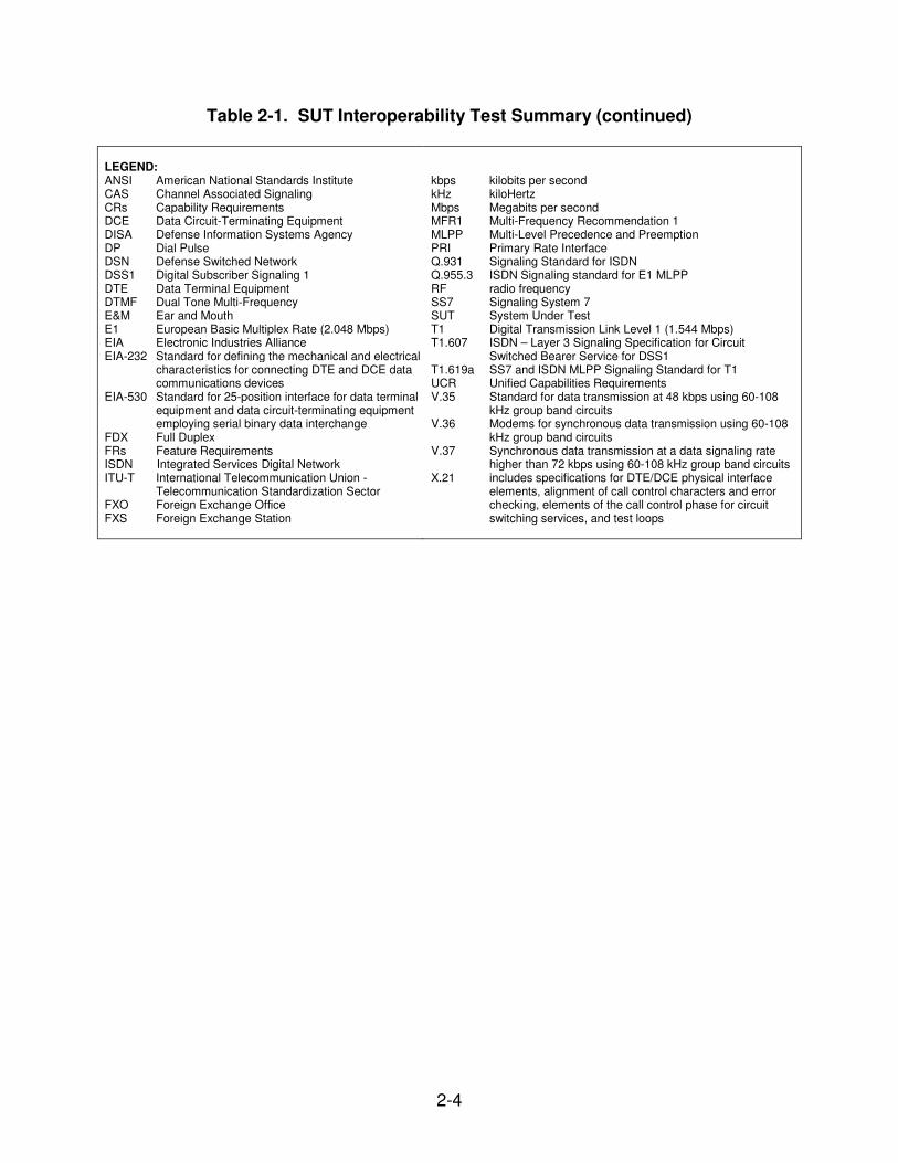
Table 2-1. SUT Interoperability Test Summary (continued) LEGEND: ANSI American National Standards Institute CAS Channel Associated Signaling CRs Capability Requirements DCE Data Circuit-Terminating Equipment DISA Defense Information Systems Agency DP Dial Pulse DSN Defense Switched Network DSS1 Digital Subscriber Signaling 1 DTE Data Terminal Equipment DTMF Dual Tone Multi-Frequency E&M Ear and Mouth E1 European Basic Multiplex Rate (2.048 Mbps) EIA Electronic Industries Alliance EIA-232 Standard for defining the mechanical and electrical
characteristics for connecting DTE and DCE data communications devices
EIA-530 Standard for 25-position interface for data terminal equipment and data circuit-terminating equipment employing serial binary data interchange
FDX Full Duplex FRs Feature Requirements ISDN Integrated Services Digital Network ITU-T International Telecommunication Union -
Telecommunication Standardization Sector FXO Foreign Exchange Office FXS Foreign Exchange Station
kbps kilobits per second kHz kiloHertz Mbps Megabits per second MFR1 Multi-Frequency Recommendation 1 MLPP Multi-Level Precedence and Preemption PRI Primary Rate Interface Q.931 Signaling Standard for ISDN Q.955.3 ISDN Signaling standard for E1 MLPP RF radio frequency SS7 Signaling System 7 SUT System Under Test T1 Digital Transmission Link Level 1 (1.544 Mbps) T1.607 ISDN – Layer 3 Signaling Specification for Circuit
Switched Bearer Service for DSS1 T1.619a SS7 and ISDN MLPP Signaling Standard for T1 UCR Unified Capabilities Requirements V.35 Standard for data transmission at 48 kbps using 60-108
kHz group band circuits V.36 Modems for synchronous data transmission using 60-108
kHz group band circuits V.37 Synchronous data transmission at a data signaling rate
higher than 72 kbps using 60-108 kHz group band circuits X.21 includes specifications for DTE/DCE physical interface
elements, alignment of call control characters and error checking, elements of the call control phase for circuit switching services, and test loops

2-5
Table 2-2. SUT Capability and Feature Interoperability Requirements
DSN Access Interfaces
Interface Critical Requirements
Required or Conditional References
T1 PRI (ANSI T1.607/ANSI
T1.619a)
T1 CAS (DTMF/MFR1/DP)
T1 SS7 (ANSI T1.619a)
No
1
No1
No1
• DS1 Interface Characteristics (C) as specified in UCR 2008, Section 5.2.6.1
• DS1 Supervisory Channel Associated Signaling (C) as specified in UCR 2008, Section 5.2.6.1
• DS1 Clear Channel Capability (C) as specified in UCR 2008, Section 5.2.6.1 (SS7 and PRI only)
• DS1 Alarm and Restoral Requirements (C) as specified in UCR 2008, Section 5.2.6.1
• MOS (R)
• BERT (R)
• Secure Transmission (Voice and Data) (R) as specified in UCR 2008, Section 5.2.12.6
• Modem (R)
• Facsimile (R)
• Call Control Signals (R)
• Alarms (R) as specified in UCR 2008, Section 5.2.1.5.7
• Call Congestion Control (R)
• Call Congestion for TDM Transport (C)
• Voice Compression (C)
• UCR Section 5.9.2.3.4
• UCR Section 5.9.2.3.4
• UCR Section 5.9.2.3.4
• UCR Section 5.9.2.3.4
• UCR Section 5.9.2.1
• UCR Section 5.9.2.1
• UCR Section 5.9.2.1
• UCR Section 5.9.2.1
• UCR Section 5.9.2.1
• UCR Section 5.9.2.1
• UCR Section 5.9.2.1.1
• UCR Section 5.9.2.1.2
• UCR Section 5.9.2.1.2.1
• UCR Section 5.9.2.2
E1 PRI (ITU-T Q.931/ ITU-T Q.955.3)
E1 CAS (DTMF/MFR1/DP)
E1 SS7 (ANSI T1.619a)
No1
No1
No1
• E1 Interface Characteristics (C) as specified in UCR 2008, Section 5.2.6.2
• E1 Supervisory Channel Associated Signaling (C) as specified in UCR 2008, Section 5.2.6.2
• E1 Clear Channel Capability (C) as specified in UCR 2008, Section 5.2.6.2
• E1 Alarm and Restoral Requirements (C) as specified in UCR 2008, Section 5.2.6.2
• MOS (R)
• BERT (R)
• Secure Transmission (Voice and Data) (R) as specified in UCR 2008, Section 5.2.12.6
• Modem (R)
• Facsimile (R)
• Call Control Signals (R)
• Alarms (R) as specified in UCR 2008, Section 5.2.1.5.7
• Call Congestion Control (R)
• Call Congestion for TDM Transport (C)
• Voice Compression (C)
• UCR Section 5.9.2.3.5
• UCR Section 5.9.2.3.5
• UCR Section 5.9.2.3.5
• UCR Section 5.9.2.3.5
• UCR Section 5.9.2.1
• UCR Section 5.9.2.1
• UCR Section 5.9.2.1
• UCR Section 5.9.3.1
• UCR Section 5.9.2.1
• UCR Section 5.9.2.1
• UCR Section 5.9.2.1.1
• UCR Section 5.9.2.1.2
• UCR Section 5.9.2.1.2.1
• UCR Section 5.9.2.2
ITU-T V.35, ITU-T V.36, ITU-T V.37
EIA-232, EIA-530, ITU-T X.21,
No1
• Serial Interface Characteristics (C) as specified in UCR 2008, Section 5.2.6.4
• BERT (R)
• UCR Section 5.9.2.3.2
• UCR Section 5.9.2.1
E&M (Type I, II, III, IV), FXS and FXO
(2-wire Analog)
No1
• Analog 2 Wire and 4 Wire Interface Characteristics (C) as specified in UCR 2008, Section 5.2.6.4
• MOS (R)
• BERT (R)
• Secure Transmission (Voice and Data) (R) as specified in UCR 2008, Section 5.2.12.6
• Modem (R)
• Facsimile (R)
• Call Control Signals (R)
• Alarms (R) as specified in UCR 2008, Section 5.2.1.5.7
• Call Congestion Control (R)
• Call Congestion for TDM Transport (C)
• Voice Compression (C)
• UCR Section 5.9.2.3.1
• UCR Section 5.9.2.1
• UCR Section 5.9.2.1
• UCR Section 5.9.2.1
• UCR Section 5.9.2.1
• UCR Section 5.9.2.1
• UCR Section 5.9.2.1
• UCR Section 5.9.2.1.1
• UCR Section 5.9.2.1.2
• UCR Section 5.9.2.1.2.1
• UCR Section 5.9.2.2
2-6
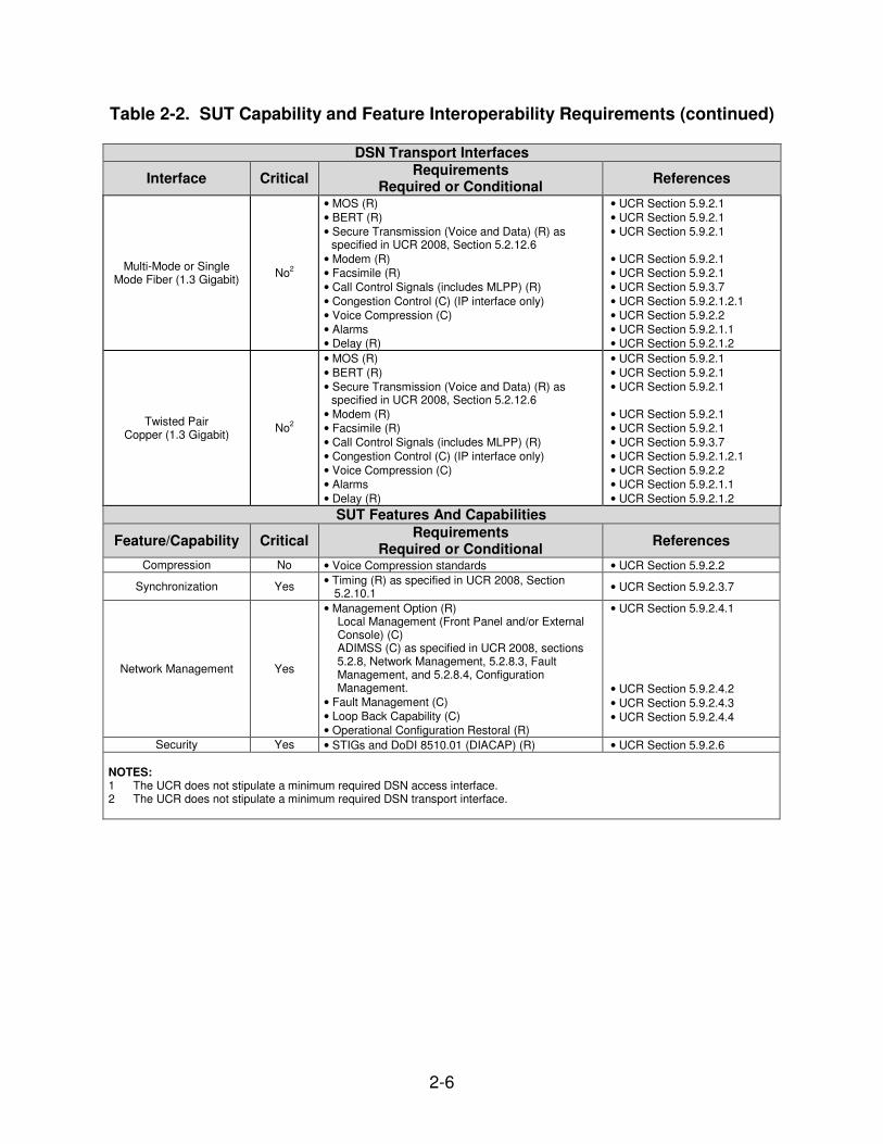
Table 2-2. SUT Capability and Feature Interoperability Requirements (continued)
DSN Transport Interfaces
Interface Critical Requirements
Required or Conditional References
Multi-Mode or Single Mode Fiber (1.3 Gigabit)
No2
• MOS (R)
• BERT (R)
• Secure Transmission (Voice and Data) (R) as specified in UCR 2008, Section 5.2.12.6
• Modem (R)
• Facsimile (R)
• Call Control Signals (includes MLPP) (R)
• Congestion Control (C) (IP interface only)
• Voice Compression (C)
• Alarms
• Delay (R)
• UCR Section 5.9.2.1
• UCR Section 5.9.2.1
• UCR Section 5.9.2.1
• UCR Section 5.9.2.1
• UCR Section 5.9.2.1
• UCR Section 5.9.3.7
• UCR Section 5.9.2.1.2.1
• UCR Section 5.9.2.2
• UCR Section 5.9.2.1.1
• UCR Section 5.9.2.1.2
Twisted Pair Copper (1.3 Gigabit)
No2
• MOS (R)
• BERT (R)
• Secure Transmission (Voice and Data) (R) as specified in UCR 2008, Section 5.2.12.6
• Modem (R)
• Facsimile (R)
• Call Control Signals (includes MLPP) (R)
• Congestion Control (C) (IP interface only)
• Voice Compression (C)
• Alarms
• Delay (R)
• UCR Section 5.9.2.1
• UCR Section 5.9.2.1
• UCR Section 5.9.2.1
• UCR Section 5.9.2.1
• UCR Section 5.9.2.1
• UCR Section 5.9.3.7
• UCR Section 5.9.2.1.2.1
• UCR Section 5.9.2.2
• UCR Section 5.9.2.1.1
• UCR Section 5.9.2.1.2
SUT Features And Capabilities
Feature/Capability Critical Requirements
Required or Conditional References
Compression No • Voice Compression standards • UCR Section 5.9.2.2
Synchronization Yes • Timing (R) as specified in UCR 2008, Section
5.2.10.1 • UCR Section 5.9.2.3.7
Network Management Yes
• Management Option (R) Local Management (Front Panel and/or External Console) (C)
ADIMSS (C) as specified in UCR 2008, sections 5.2.8, Network Management, 5.2.8.3, Fault Management, and 5.2.8.4, Configuration Management.
• Fault Management (C)
• Loop Back Capability (C)
• Operational Configuration Restoral (R)
• UCR Section 5.9.2.4.1
• UCR Section 5.9.2.4.2
• UCR Section 5.9.2.4.3
• UCR Section 5.9.2.4.4
Security Yes • STIGs and DoDI 8510.01 (DIACAP) (R) • UCR Section 5.9.2.6 NOTES: 1 The UCR does not stipulate a minimum required DSN access interface. 2 The UCR does not stipulate a minimum required DSN transport interface.

2-7
Table 2-2. SUT Capability and Feature Interoperability Requirements (continued) LEGEND: ADIMSS Advanced DSN Integrated Management Support
System ANSI American National Standards Institute BERT Bit Error Rate Test C Conditional CAS Channel Associated Signaling DCE Data Circuit-Terminating Equipment DIACAP Department of Defense Information Assurance
Certification and Accreditation Process DoDI Department of Defense Instruction DP Dial Pulse DS1 Digital Signal Level 1 DSN Defense Switched Network DSS1 Digital Subscriber Signaling 1 DTE Data Terminal Equipment DTMF Dual Tone Multi-Frequency E&M Ear and Mouth E1 European Basic Multiplex Rate (2.048 Mbps) EIA-232 Standard for defining the mechanical and
electrical characteristics for connecting DTE and DCE data communications devices
EIA-530 Standard for 25-position interface for data terminal equipment and data circuit-terminating equipment employing serial binary data interchange
FXO Foreign Exchange Office FXS Foreign Exchange Station ISDN Integrated Services Digital Network ITU-T International Telecommunication Union -
Telecommunication Standardization Sector
kbps kilobits per second kHz kiloHertz Mbps Megabits per second MFR1 Multi-Frequency Recommendation 1 MLPP Multi-Level Precedence and Preemption MOS Mean Opinion Score PRI Primary Rate Interface Q.931 Signaling Standard for ISDN Q.955.3 ISDN Signaling standard for E1 MLPP R Required SS7 Signaling System 7 STIGs Security Technical Implementation Guides SUT System Under Test T1 Digital Transmission Link Level 1 (1.544 Mbps) T1.607 ISDN – Layer 3 Signaling Specification for Circuit
Switched Bearer Service for DSS1 T1.619a SS7 and ISDN MLPP Signaling Standard for T1 TDM Time Division Multiplexing UCR Unified Capabilities Requirements V.35 Standard for data transmission at 48 kbps using 60-108
kHz group band circuits V.36 Modems for synchronous data transmission using 60-
108 kHz group band circuits V.37 Synchronous data transmission at a data signaling rate
higher than 72 kbps using 60-108 kHz group band circuits
X.21 includes specifications for DTE/DCE physical interface elements, alignment of call control characters and error checking, elements of the call control phase for circuit switching services, and test loops
9. TEST NETWORK DESCRIPTION. The SUT was tested at USAISEC TIC in a manner and configuration similar to that of the DSN operational environment. This testing was conducted using the test configurations shown in Figure 2-2. Non-secure voice, non-secure data, video, bit error rate, and test calls were placed over the SUT. The 60 decibel (dB) in line attenuation represents a minimal signal loss when using the 4416 MHz frequency. UCR testing confirms suitable operations based on published requirements. The UCR does not include specifications for the maximum separation range of the devices.

2-8
LEGEND: APL Approved Product List CAT5 Category 5 Cable (Twisted Pair) dB Decibel (unit of power and intensity) DISN Defense Information Systems Network DSN Defense Switch Network PoE Power Over Ethernet
PIDU Powered Indoor Unit PTP Point To Point ODU Outdoor Unit RF Radio Frequency UC Unified Capabilities
Figure 2-2. SUT Test Configuration
2-9
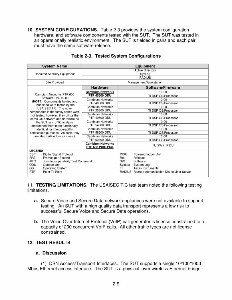
10. SYSTEM CONFIGURATIONS. Table 2-3 provides the system configuration hardware, and software components tested with the SUT. The SUT was tested in an operationally realistic environment. The SUT is fielded in pairs and each pair must have the same software release.
Table 2-3. Tested System Configurations
System Name Equipment
Required Ancillary Equipment
Active Directory
SysLog
RADIUS
Site Provided Management Workstation
Cambium Networks PTP 600 Software Rel. 10-00
(NOTE: Components bolded and underlined were tested by the
USAISEC TIC. The other components in the family series were not tested; however, they utilize the same OS software and hardware as
the SUT, and JITC analysis determined them to be functionally
identical for interoperability certification purposes. As such, they
are also certified for joint use.)
Hardware Software/Firmware
Cambium Networks PTP 45600 ODU
10-00
TI DSP OS/Processor
Cambium Networks PTP 48600 ODU
10-00 TI DSP OS/Processor
Cambium Networks PTP 25600 ODU
10-00
TI DSP OS/Processor
Cambium Networks PTP 49600 ODU
10-00
TI DSP OS/Processor
Cambium Networks PTP 54600 ODU
10-00 TI DSP OS/Processor
Cambium Networks PTP 58600 ODU
10-00
TI DSP OS/Processor
Cambium Networks PTP 59600 ODU
10-00
TI DSP OS/Processor Cambium Networks PTP 600 PIDU Plus
No SW in PIDU
LEGEND: DSP Digital Signal Protocol FPS Frames per Second JITC Joint Interoperability Test Command ODU Outdoor Unit OS Operating System PTP Point To Point
PIDU Powered Indoor Unit Rel. Release SW Software SysLog System Log TI Texas Instruments RADIUS Remote Authentication Dial-In User Server
11. TESTING LIMITATIONS. The USAISEC TIC test team noted the following testing limitations.
a. Secure Voice and Secure Data network appliances were not available to support testing. An SUT with a high quality data transport represents a low risk to successful Secure Voice and Secure Data operations.
b. The Voice Over Internet Protocol (VoIP) call generator is license constrained to a capacity of 200 concurrent VoIP calls. All other traffic types are not license constrained.
12. TEST RESULTS a. Discussion (1) DSN Access/Transport Interfaces. The SUT supports a single 10/100/1000 Mbps Ethernet access interface. The SUT is a physical layer wireless Ethernet bridge
2-10
using a proprietary adaptive wireless transport interface with a single 10/100/1000 Mbps Ethernet access interface. Testing was conducted with the use of test tools simulating the traffic generated by actual edge devices. The IXIA IxChariot, in association with related performance endpoints, was used as the primary test tool generating and analyzing the various traffic types. Other test tools were used as a secondary confirmation and backup test capability. These include Iperf and Wireshark software utilities. The specific requirements and test results tested over the SUT DSN access and transport interfaces are described in the subparagraphs below.
(a) IP Interface Characteristics. The UCR 2008 Change 2, section 5.9.2.1.2.2, states conditionally: “The NE(s) using IP transport shall implement IP congestion control. Congestion may be controlled by using DiffServ, which shall be capable of providing preferential treatment for call congestion over other media types IAW Section 5.3.3, Network Infrastructure End-to-End Performance Requirements, and a capability to limit the provisioning of input and output interfaces so congestion is impossible under the worst transport congestion scenario. The IP interface parameters subject to ingress or egress requirements shall be met IAW Section 5.9.2.3.9, IP Interface.” IP Traffic using dissimilarly encoded Differentiated Services Code Points (DSCP) was sent across the SUT along with traffic encoded as best effort; DSCP = 00. Analyzing the traffic characteristics at the distant end provides the confirmation the SUT supports DSCP for traffic management. The SUT supported proper classification of traffic based on DSCP encoding. It provided traffic priority based on the DSCP encoding. It did not modify DSCP encodings on traffic traversing the SUT. These results were consistent on all tests run using the SUT. These results confirm the SUT supports DSCP as a form of congestion control, as required by UCR 2008 Change 2.
(b) E2E Average MOS. The UCR 2008 Change 2, section 5.9.2.1.1, states:
“The introduction of an NE(s) shall not cause the E2E average MOS to fall below 4.0 as measured over any 5-minute time interval.” The SUT consistently demonstrated MOS averages of 4.3 above the requirement threshold in accordance with UCR 2008 Change 2, section 5.9.2.1.1. The SUT meets this requirement.
(c) E2E Measured Bit Error Rate (BER). The UCR 2008 Change 2, section
5.9.2.1.2, states: “The introduction of an NE(s) shall not degrade the E2E measured BER to no more than 0.03 percent from the baseline minimum E2E digital BER requirement, which is not more than one error in 1x109 bits (averaged over a 9-hour period).” The SUT supports a single Ethernet IP interface, so there is no direct BER measurement possible. The SUT demonstrated 10 hours of continuous data (VoIP and Best Effort traffic) transfer service with 0.000 % bytes lost. The SUT demonstrated consistently high quality data transfers representative of meeting and beneficially exceeding the Measured BER requirement, in accordance with UCR 2008 Change 2, section 5.9.2.1.2.
(d) DoD Secure Communications Devices (DSCD) Operations. The UCR
2008 Change 2, section 5.9.2.1.3, states: “The introduction of an NE(s) shall not degrade secure transmission for secure end devices as defined in Section 5.2.2, DoD
2-11
Secure Communications Devices.” Reference the associated, published Letter of Sameness, Motorola Test Discrepancy Report (TDR) line number: M10001 for information. This requirement was written for use with an analog interface and not appropriate to an Ethernet interface. There were no DSCDs available to support direct testing with the SUT. The SUT consistently demonstrated high quality data transfers with no errors throughout testing. The SUT’s error free operations demonstrate a low risk for degradation to suitable DSCD operations, in accordance with UCR 2008 Change 2, section 5.9.2.1.3.
(e) Modem Transmissions. The UCR 2008 Change 2, section 5.9.2.1.4,
states: “The NE(s) shall support a minimum modem transmission speed of 9.6 kbps across the associated NE(s).” The SUT does not have an analog serial interface. The SUT supports a single 10/100/1000 Mbps Ethernet port. Reference the associated, published Letter of Sameness, Motorola TDR line number: M10002 for information. This requirement was written for use with an analog interface and is not appropriate with an Ethernet interface. The SUT met UCR for operations at 10 and 100 Mbps FDX Ethernet for all tests. The 1000 Mbps FDX Ethernet operations did not meet UCR requirement 5.3.1.3.1, General Performance Parameters; Non-Blocking, for sufficient link capacity in this interface mode. The SUT’s 1000 Mbps FDX Ethernet interface mode maximum throughput was 300 Mbps. This is concurrent with the SUT vendor’s maximum throughput specification of 300 Mbps which saturates the RF link. Thus, the SUT operating in the 10/100 Mbps FDX Ethernet mode meets UCR. The SUT’s consistent high quality data transfer characteristics represent the ability to meet and beneficially exceed the Modem Transmission requirement, in accordance with UCR 2008 Change 2, section 5.9.2.1.4.
(f) Facsimile Transmission. The UCR 2008 Change 2, section 5.9.2.1.5
states: “The NE(s) shall support a minimum facsimile transmission speed of 9.6 kbps across the associated NE(s).” The SUT does not have an analog serial interface. The SUT supports a single 10/100/1000 Mbps Ethernet port. Reference the associated, published Letter of Sameness, Motorola TDR line number: M10003 for information. This requirement was written for use with an analog interface and is not appropriate with an Ethernet interface. The SUT met UCR for operations at 10 and 100 Mbps FDX Ethernet for all tests. The 1000 Mbps FDX Ethernet operations did not meet UCR requirement 5.3.1.3.1, General Performance Parameters; Non-Blocking, for sufficient link capacity in this interface mode. The SUT’s 1000 Mbps FDX Ethernet interface mode maximum throughput was 300 Mbps. This is concurrent with the SUT vendor’s maximum throughput specification of 300 Mbps, which saturates the RF link. Thus the SUT operating in the 10/100 Mbps FDX Ethernet mode meets UCR. The SUT’s consistent high quality data transfer characteristics and representatively high quality VoIP call transfer characteristics represent the SUT’s ability to meet and beneficially exceed the Facsimile Transmission requirement, in accordance with UCR 2008 Change 2, section 5.9.2.1.5.
(g) Call Control Signals. The UCR 2008 Change 2, section 5.9.2.1.6,
states: “The NE shall transport all call control signals transparently on an E2E basis.”

2-12
Reference the associated, published Letter of Sameness, Motorola TDR line number: M10004 for information. This requirement was written for use with an analog interface and is not appropriate with an Ethernet interface. The SUT is a 10/100 Ethernet Bridge which transports all properly crafted Ethernet frames. The SUT consistently demonstrated high quality data transfer characteristics. Testing using a variety of deliberately crafted information encoded into Ethernet frames confirmed accurate and reliable transport across the SUT. This is representative of the ability to successfully convey Call Control Signals properly encoded in Ethernet frames. The SUT’s consistent high quality data and VoIP call transfer characteristics represent the ability to meet and beneficially exceed the transport of Call Control Signals requirement, in accordance with UCR 2008 Change 2, section 5.9.2.1.6.
(h) IP Interface Delay Requirement. The UCR 2008 Change 2, section
5.9.2.3.9.1.a, states: “The addition of NEs with IP transports shall not increase the one-way latency per NE pair when measured from end to end over any 5-minute period specified for Time Division Multiplexing ingress G.711 (non-secure calls) to non-transcoding G.711 IP egress and shall not increase delay more than 50 ms per NE pair as measured end-to-end.” The 50 ms delay represents the most stringent requirement in this section. The SUT delay (one way latency) consistently measured at an average value of 3 ms. The SUT’s average delay of 3 ms represents the ability to meet and beneficially exceed the IP Interface Delay requirement, in accordance with UCR 2008 Change 2, section 5.9.2.3.9.1.a.
(i) IP lnterface Jitter Requirements. The UCR 2008 Change 2, section
5.9.2.3.9.1.b, states: “The addition of an NE shall not cause jitter measured from ingress to egress to increase by more than 5 ms averaged over any 5-minute period.” The SUT consistently produced jitter measurements that averaged 0.9 ms. The SUT’s jitter measurements met and beneficially exceed the IP Interface Jitter requirement in accordance with UCR 2008 Change 2, section 5.9.2.3.9.1.b.
(j) IP Interface Packet Loss. The UCR 2008 Change 2, section
5.9.2.3.9.1.c, states: “The addition of an NE shall not cause packet loss measured from ingress to egress to increase by more than 0.05 percent averaged over any 5-minute period.” The SUT consistently produced packet loss measurements of 0.0%. The SUT’s packet loss measurement met and beneficially exceeded the IP Interface Packet Loss requirement in accordance with UCR 2008 Change 2, section 5.9.2.3.9.1.c.
(2) Device Management (a) Management Option. The UCR 2008 Change 2, section 5.9.2.4.1.1.b.1, states: “The NE shall provide network management (NM) data/monitoring via one or more of the following physical interfaces: Ethernet/TCP/IP (IEEE 802.3), Serial (RS-232)/Asynchronous, Serial/Synchronous (X.25 and/or BX.25 variant).” The SUT supports secure web management using the Ethernet/TCP/IP (IEEE 802.3) interface. Using this Graphical User Interface, the administrator can perform the
2-13
following: view alarms, review system logging events, monitor performance metrics, and execute network management tasks. The SUT meets the Management Option in accordance with UCR 2008 Change 2, section 5.9.2.4.1.1.b.1. (b) Fault Management. The UCR 2008 Change 2, section 5.9.2.4.2, states: “The NE shall report any failure of self-test diagnostic function on non-active and active channels on a noninterference basis to the assigned NMS.” The SUT supports fault management using a secure management workstation. The SUT meets the Fault Management requirement in accordance with UCR 2008 Change 2, section 5.9.2.4.2. (c) Operational Configuration Restoral. The UCR 2008 Change 2, section 5.9.2.4.4, states: “Loss of power should not remove configuration settings. Unit should be restored to the last customer-configured state before the power loss, without intervention when power is restored.” The SUT consistently recovered successfully to an operational state when subjected to multiple power failure conditions. The SUT returned to the last customer configured state prior to the power failure. The SUT meets the Operational Configuration Restoral requirement in accordance with UCR 2008 Change 2, section 5.9.2.4.4. (3) Security. The UCR Change 2, section 5.9.2.6, states: “All components of the NE shall meet security requirements for each supported mode, as outlined in DoDI 8510.01 and the applicable STIG(s).” Security is tested as part of the Information Assurance testing and is covered under a separate report, Reference (e). b. System Interoperability Results. The SUT meets all of its critical interoperability requirements set forth in Reference (c) for a Fixed Network Element (FNE) and is certified as interoperable for joint use within the Defense Information System Network (DISN). When connected to the interfaces certified in this letter, the SUT and its associated applications were transparent to the switching systems interfaced, causing no degradation of service or negative impact, and met all the critical interoperability requirements.

2-14
13. TEST AND ANALYSIS REPORT. No detailed test report was developed in accordance with the Program Manager’s request. JITC distributes interoperability information via the JITC Electronic Report Distribution (ERD) system, which uses Unclassified-But-Sensitive Internet Protocol Router Network (NIPRNet) e-mail. More comprehensive interoperability status information is available via the JITC System Tracking Program (STP). The STP is accessible by .mil/gov users on the NIPRNet at https://stp.fhu.disa.mil. Test reports, lessons learned, and related testing documents and references are on the JITC Joint Interoperability Tool (JIT) at http://jit.fhu.disa.mil (NIPRNet). Information related to DSN testing is on the Telecom Switched Services Interoperability (TSSI) website at http://jitc.fhu.disa.mil/tssi. Due to the sensitivity of the information, the Information Assurance Accreditation Package (IAAP) that contains the approved configuration and deployment guide must be requested directly through government civilian or uniformed military personnel from the Unified Capabilities Certification Office (UCCO), e-mail: [email protected].