Embed Size (px)
DESCRIPTION
Balint Seeber's All Your RFz Are Belong to Me. Presentation slides from Defcon21. In this presentation, he explores many topics including decoding GSM cell phone signals, automatic mapping of radio towers, hospital pager systems, air traffic messages, parallel decoding of many signals at once (including frequency-hopping ones), satellite signals, and doppler direction finding. 345 Slides in total. Mostly images.
Citation preview

All Your RFz Are Belong to Me:Hacking the Wireless World with Software Defined Radio
Balint [email protected]@spenchdotnet
Notes and links in PDF comments on each slide
Applications [email protected]

Overview
• RF 101
• The journey into Software Defined Radio
• Hospital pager systems
• Tracking planes
• Decoding satellite‐downlink traffic
• Direction Finding

The Electromagnetic Spectrum
• Electromagnetism: one of four universal forces
• Radio wave exists due to energy being propagated at a particular frequency
• Can create and receive radio waves using electronics
Transmitting Data
• Radio (carrier) wave must be modulated to convey information
Time
Amplitu
de

Transmitting Data
• Radio (carrier) wave must be modulated to convey information
• OOK (On‐Off Keying)– Presence/absence of a signal
• COFDM (Coded Orthogonal Frequency‐Division Multiplexing)– WiFi, DVB, DAB, WiMAX, UWB, 4G, ADSL, PLC

Transmitting Data
InformationModulator
CarrierRF Hardware

AM & FM: In the Time DomainAnalog or digitalinformation
Constant frequency
Constant amplitude

In the Frequency Domain
Time
Amplitude for each frequency
Frequency

Modulation
• Modulation technique defines how the signal will look on the spectrum
AM FM C4FMTime
FrequencyFrequency
Carrier
Time
Frequency

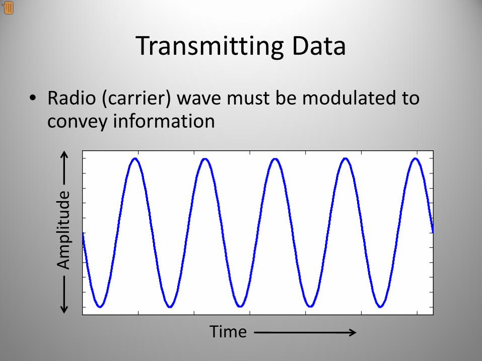
Hardware
• Crystal set receiver– Powerful AM transmissions
Hardware
• Crystal set receiver– Powerful AM transmissions

Hardware
• Crystal set receiver– Powerful AM transmissions
• More advanced hardware to handle increasingly complex modulation schemes– FM, stereo FM, microwave, digital…

Modulation in Hardware
• MOdulation and DE‐Modulation traditionally performed in hardware
• ‘Black box’ implementation– Not re‐configurable
• Modern digital hardware allows more flexibility
Radyne Comstream DMD‐15 Satellite Modem

The journey begins…

Genesis of RFMap
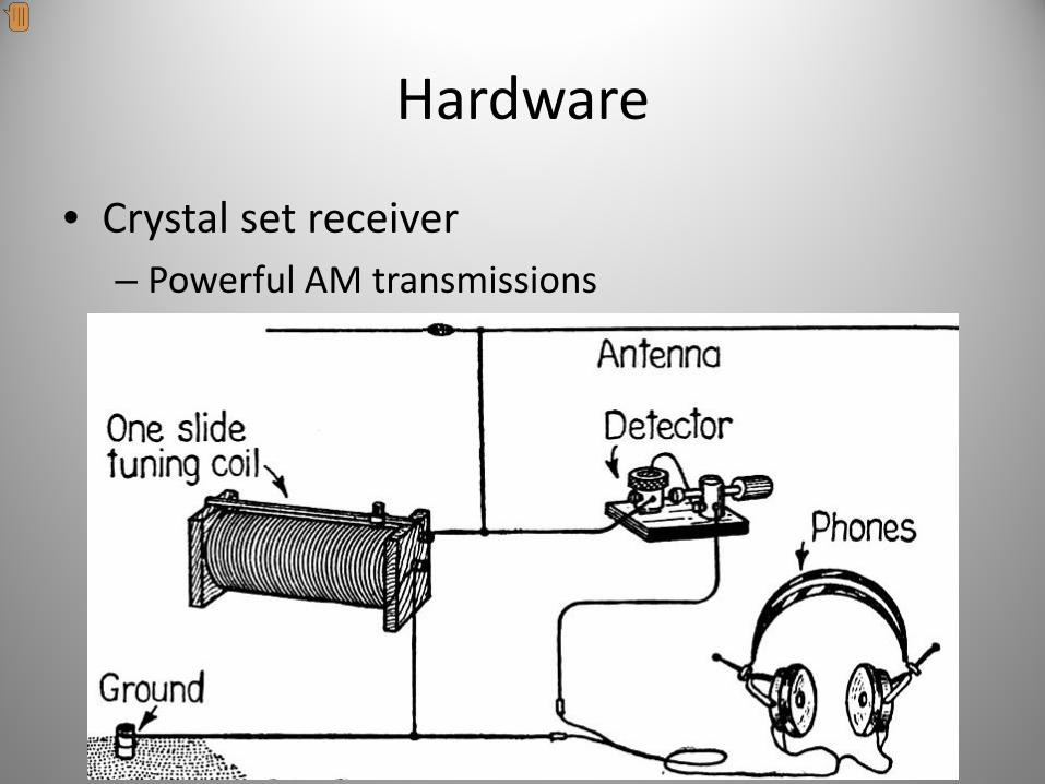
GSM + Gammu + Wireshark

Field Test Mode<1983> MDI:d2m/RSSI_RESULTS t=0afe nr=73: D 83:00 00 b1 b1 00 65 ab a3 b1 a0 a0 a6 9d a1 80 a4 80 80 80 80 80 80 80 aa

Geolocation with GSM

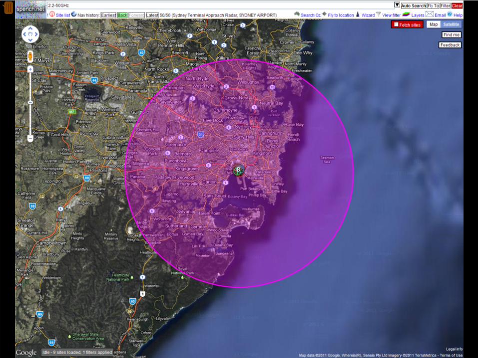
RFNetMapper
Determine accuracy by comparing to ground truth:where are the base stations?

ACMA RadCom Web Interface

Enter RFMap…

The RFMap web interface

All sites, point‐to‐point links &elevation data

Registered TX Sites

Registered TX Sites

Registered TX Sites

NASA SRTM Elevation Data

Site details: frequency assignments

Antenna radiation pattern*


AntennaRadiationEnvelope

Radiation Heatmap

Amateur Radio Operators (HAMs)


Most popular sites

Defence & ECHELON

“Joint Space Defence Research”

Upset ADIRU of QF68/71/72 & JQ7 ?

Side note
Bolivia


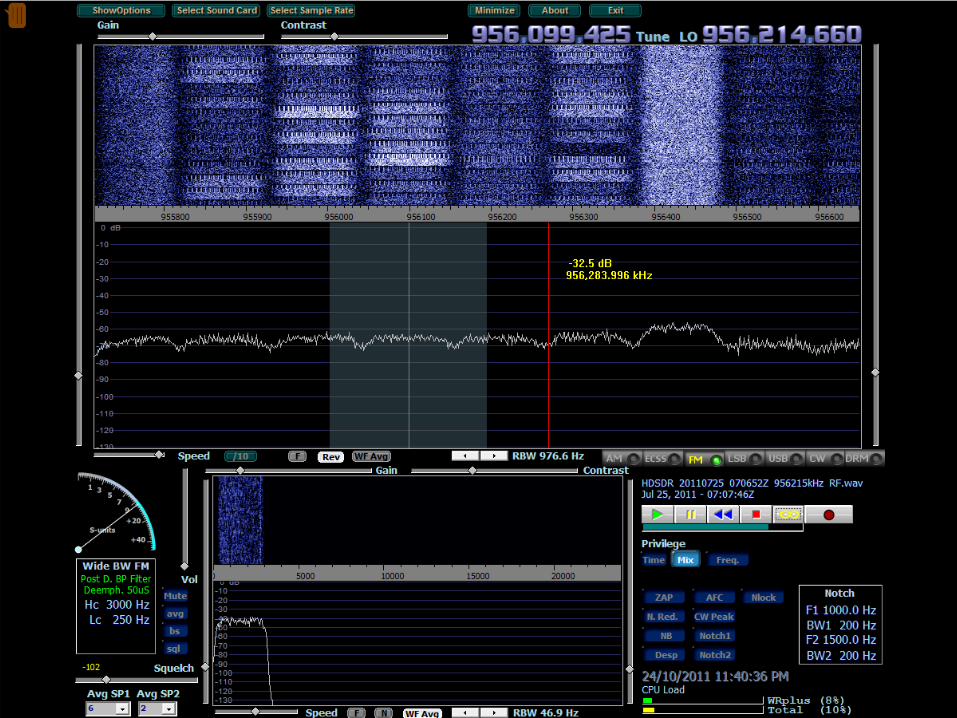
The Mystery Signal
Rate at which ‘messages’ were transmitted varied throughout the day:
correlates with increased daytime activity.
Received RF signal audio sampled by soundcard streamed across network

Step One: Look at the signalRadio is already set to receive N‐FM (narrowband frequency modulated signal)
Signal in the time domain (voltage vs. time):
Signal in the frequency domain (intensity of frequency bins vs. time):
IT’S SLICER TIME!
Preamble Payload

AudioDataDecoder
Running state of decoder
UntrainedPreamblePayload
Frequency analysis (FFT) of signal:Two frequencies of interest

Step Two: FFT of 2FSK Bitstream
• Lock on two frequencies (Frequency Shift Keying)• Sample intensity of each at regular interval (baud rate)• Pick which is the strongest:
low = 0 bit, high = 1 bit

Step Three: Data Information
• The most difficult part, so try all combinations
Wikipedia says:

POCSAG!
• “Post Office Code Standardization Advisory Group”
• Standard decoding software didn’t work
• Key: recognisable sequence of bits when idle
Look for known codewords/repeated bit strings

Hospital Pager Systems
• High power, better penetration than mobiles
• Personnel carry small pagers, each with ID mapped to Radio Identity Code
• Mostly numeric pages with phone extension
• Sent via software on any computer at hospital
• Address to multiple recipients, automatically sent to each once
• Delivery not guaranteed

Frequencies
• Shared frequency: 148.1375 MHz (standard)
• Private systems in 800/900MHz band:
Non‐standard FSK ignored by decoders
‘Testing’

On RFMap

Sydney West Area Health Service

North ShoreGosford
Prince of Wales: 38, etc.
Hospital ID Postfix

Sensitive Information

Image by Oscar De Lellis
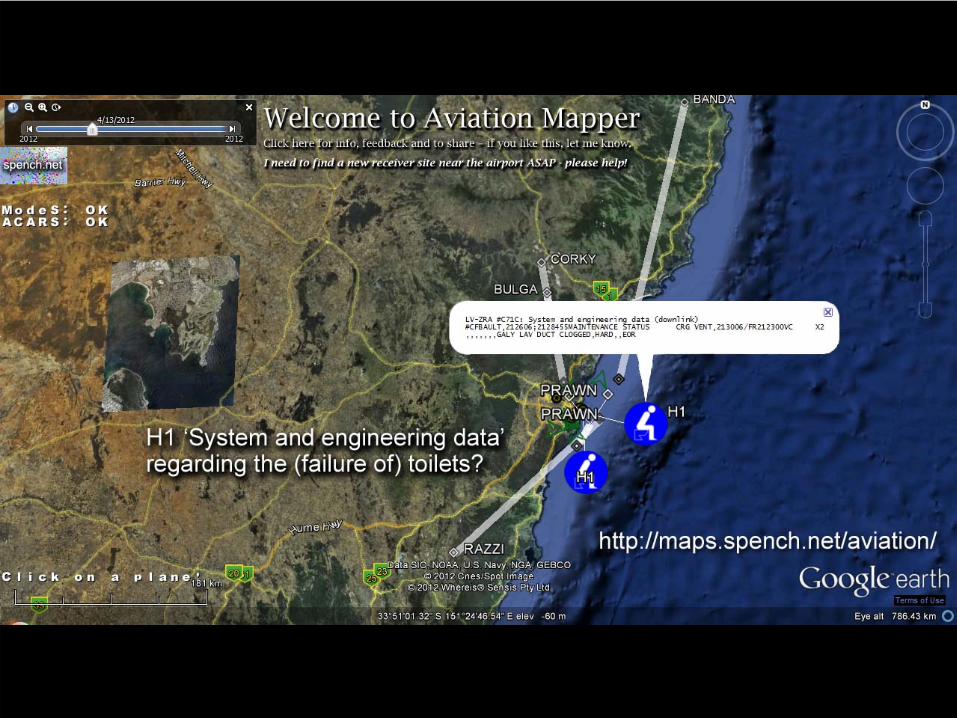
AviationMapper

590 km/h10706 ft

YSSY YMML

YSSY YMML


ATCRBS, PSP & SSR
• Air Traffic Control Radar Beacon System– Primary Surveillance Radar
– Secondary Surveillance Radar
Primary:• Traditional RADAR• ‘Paints skins’ and listens for return• Identifies and tracks primary targets, while ignoring ‘ground clutter’• Range limited by RADAR equation ( )4
1d

ATCRBS, PSP & SSR
• Air Traffic Control Radar Beacon System– Primary Surveillance Radar
– Secondary Surveillance Radar
Secondary:• Directional radio• Requires transponder• Interrogates transponders, which reply with squawk code, altitude, etc.• Increased range ( )2
1d


The Modes
• A: reply with squawk code• C: reply with altitude• S: enables Automatic Dependant Surveillance‐Broadcast (ADS‐B), and the Aircraft/Traffic Collision Avoidance System (ACAS/TCAS)
• Mode S not part of ATCRBS, but uses same radio hardware (same frequencies)– Increasing problem of channel congestion
SSR

The Modes
• A: reply with squawk code• C: reply with altitude• S: enables Automatic Dependant Surveillance‐Broadcast (ADS‐B), and the Aircraft/Traffic Collision Avoidance System (ACAS/TCAS)
SSR

ADS‐BPosition
Heading
Altitude
Vertical rate
Flight ID
Squawk code

ATC
Mode S TX/RX: Linked to ATC (can be at airport, or remote)
Uplink:“All call” / Altitude request
Downlink:Airframe ID / Altitude response (air‐to‐ground)

ACAS/TCAS
Altitude response (air‐to‐air)
Altitude request
“PULL UP” “TRAFFIC”

Mode S sites
Uplink: 1.03 GHzDownlink: 1.09 GHz

Mode S sites
Uplink: 1.03 GHzDownlink: 1.09 GHz

Response Encoding
• Data block is created & bits control position of pulses sent by transmitter
Pulse Position Modulation (AM)
Early chipLate chip
Used to differentiate against other Modes

Pulse Position Modulation
• Pulse lasts 0.0000005 seconds (0.5 µs)• Need to sample signal at a minimum of 2 MHz (assuming you start sampling at precisely the right moment and stay synchronised)
• Requires high‐bandwidth hardware and increased processing power
• Ideally, oversample to increase accuracy

Enter Software Defined Radio…

SDR: Digitise the baseband
• Hardware is sophisticated, but purpose is simple: capture a chunk of the RF spectrum and stream it to your computer
• Computer is responsible for doing something useful with baseband data
• Instead of designing RF hardware, write it in software!
• Increased complexity/bandwidth requires more CPU power (pretty cheap)
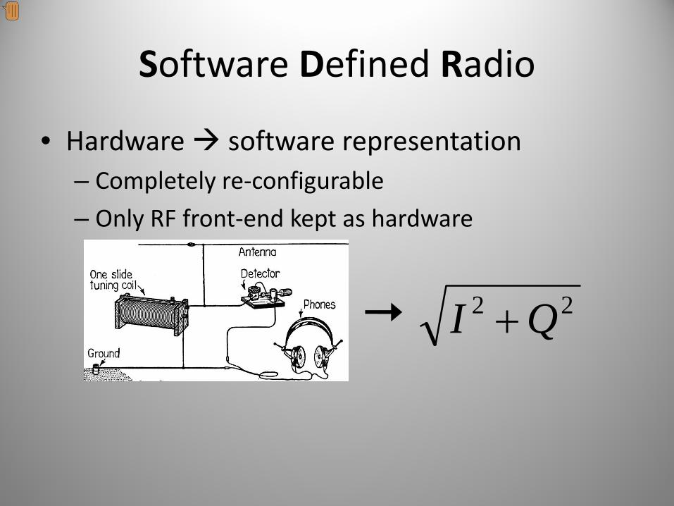
Software Defined Radio
• Hardware software representation– Completely re‐configurable
– Only RF front‐end kept as hardware
22 QI +

Software Defined Radio
• Hardware software representation– Completely re‐configurable
– Only RF front‐end kept as hardware
InformationBaseband
de‐modulator
Carrier
RF Hardware Software

Software Defined Radio
• Hardware software representation– Completely re‐configurable
– Only RF front‐end kept as hardware
• Continuous process discrete & quantised– Digital sampling producesvoltage levels
7, 9, 11, 12, 13, 14, 14, 15, 15, 15, 14, 14, 13, 12, 10, 9, 7, …
DAC
ADC

Sampling
• Nyquist‐Shannon Sampling Theorem:– “Sample at twice the highest required frequency”
– Avoid aliasing of signal

Sampling
• Nyquist‐Shannon Sampling Theorem:– “Sample at twice the highest required frequency”
– Avoid aliasing of signal
• Analog‐to‐Digital Converter (RX)
• Digital‐to‐Analog Converter (TX)
7, 9, 11, 12, 13, 14, 14, 15, 15, 15, 14, 14, 13, 12, 10, 9, 7, …
ADC
DAC

Sampling
• Nyquist‐Shannon Sampling Theorem:– “Sample at twice the highest required frequency”
– Avoid aliasing of signal
• Analog‐to‐Digital Converter (RX)
• Digital‐to‐Analog Converter (TX)
• ADC/DAC rate determines bandwidth*

Reception
• RF front‐end down‐converts signal to baseband– Zero IF receiver
• Sample & quantise baseband signal
• Simple approach would be to sample voltage level (amplitude)– Sound card

Real vs. Analytic Signals
• Real signal:– Amplitude for each sample
– One ‘real’ number
• Analytic signal:– Amplitude and phase
– ‘Real’ and ‘imaginary’ components (negative frequency)
– Encode more information

Quadrature Modulation
• Analytic signals can be sampled by having two ADCs
• Baseband must first be separated into quadrature components (real and imaginary parts)
• Mix baseband with:– In‐phase local oscillator (I channel)
– Quadrature‐phase LO (Q channel)

Sample Rate
• Analytic signal has two components– I & Q samples per sample time
• Negative frequency– Double the bandwidth
• Re‐apply Shannon’s sampling theorem:– Sampling rate directly determines bandwidth
• Produce a stream of complex stream (I/Q samples pairs) at sample rate

SDR (De‐)modulation
• Complex stream passed through mathematical functions and state machines

The
UniversalSoftwareRadioPeripheral
(USRP 1)
Sample rate = bandwidth0.25 ‐ 16 MHz
With WBX daughterboard:RX/TX: 50 MHz ‐ 2.2 GHz

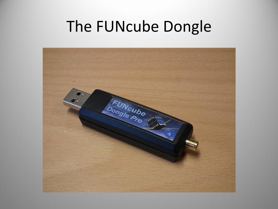
The FUNcube Dongle

RTL

Host Software
• Receive/transmit baseband samples– Analyse & display
– (De‐)modulate
– Encode/decode (extract information)
• Well‐known platforms/programs:– LabVIEW
– MATLAB Simulink
Open source? No.

GNU Radio
• Open source signal processing toolkit• Data flow paradigm
– Signals flow from sources to sinks• Intermediary blocks operate on signals
– Sources & sinks: USRP, sound card, file, network– Visualisation: FFT, waterfall, scope– Signal types: complex, float, integers– Filters: traditional building blocks used in analog and digital RF hardware
• Completely extensible (Python: high level, C++: grunt)

GNU Radio Companion

2G GSM Waterfall
8 MHz wide (8 Msps)
Broadcast control channelTraffic channel

CDMA Detection with GRC
Find repeating patterns buried within a signal
Visualise intensity of frequency components over time
Visualise instantaneousfrequency spectrum
2.1 GHz 3G
850 MHz NextG
L1 GPS

3G W‐CDMA
Signature of UMTS: repeating data in CPICH at 10 ms intervals

No apparent signal
Cyclic 1023 bit code @ 1.023 MHz chip rate
1 ms

TETRA
Frequency correction burst
Repeating idle pattern


TETR
A
π/4 DQPSK

USRP out and about


Amateur Digital Modes

The Entire HAM Band

Stereo FM with RDS: Receiver

Stereo FM with RDS: Transmitter

Sequential Scanning

Parallel Decoding

Parallel Decoding: 1
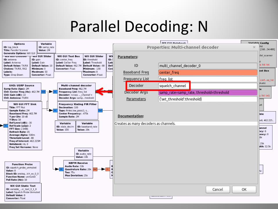
Parallel Decoding: N

OpenBTS
• Open‐source 2G GSM stack– Asterix softswitch (PBX)
– VoIP backhaul

802.11agp decoding
• 10/20 MHz OFDM
• gr‐ieee‐802‐11
• BPSK & QPSK

Other Applications of SDR
• Radio astronomy
• Passive radar
• DVB‐S decoder
• Tracking pedestrian foot traffic in shopping malls
• Much more…
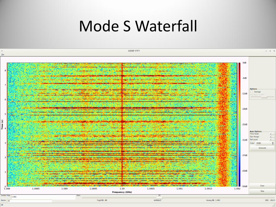
Mode S Waterfall


Time Domain
Preamble Frame

Time Domain
Preamble Frame Data bits from early/late chips
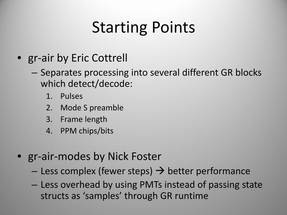
Starting Points
• gr‐air by Eric Cottrell– Separates processing into several different GR blocks which detect/decode:1. Pulses2. Mode S preamble3. Frame length4. PPM chips/bits
• gr‐air‐modes by Nick Foster– Less complex (fewer steps) better performance– Less overhead by using PMTs instead of passing state structs as ‘samples’ through GR runtime

Mode S Response: AM signal
Preamble
Payload
Decoder visualisation

Mode S Decoder Structure
Frame parser Error correction Sanity check
Pulsedetect
Preambledetect
Frame length detect
PPMdemod
…,0,1,…

Mode S Frame Types
• Several Downlink Formats (DF)– Short/long frames (56/112 bits)
• Contains Airframe Address (AA)– 24‐bit transponder address allocated by ICAO
• Appended CRC– ‘Normal’ mode (syndrome = 0)
– Address overlaid mode (syndrome = AA)
• DF 11: All call, 5/20: Identity (squawk code), 0/4/16/20: Altitude…

ADS‐B: Extended Squitter
• Several ES types (DF 17):– Standard: position, altitude, heading, vertical rate, flight ID, transponder code
– System information
– Aircraft capabilities/status (e.g. autopilot enabled)
– Aircraft intent
– Traffic information
– TCAS resolution advisories (“Pull up!”)

Making use of ADS‐B data

Making use of ADS‐B data

Making use of ADS‐B data

Making use of ADS‐B data
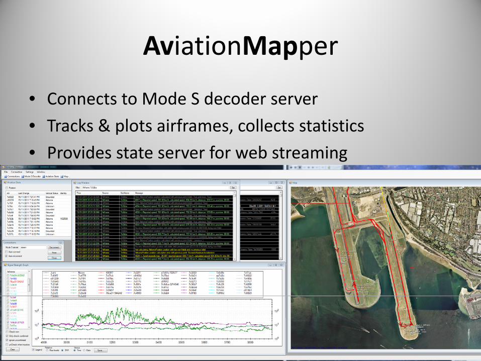
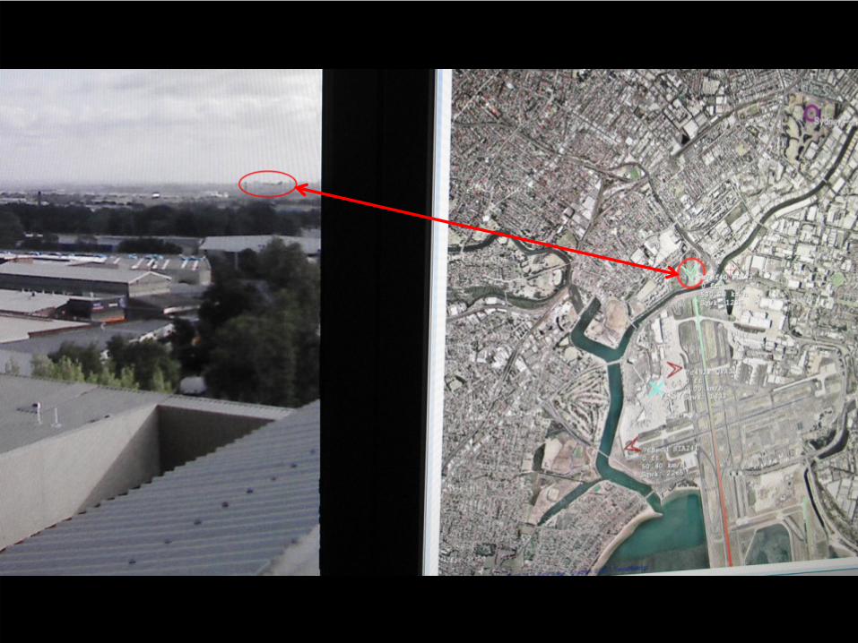
AviationMapper
• Connects to Mode S decoder server
• Tracks & plots airframes, collects statistics
• Provides state server for web streaming


Live, smooth web streaming in…

Modez Mk I


Modez Mk IIpoint5

Modez Mk III

Ground vehicle with Mode S! (inspecting perimeter?)


Next Level M
odez


BorIP
• Allows USRP 1 and computer to be separated by LAN– Control radio via TCP
– Stream baseband via UDP
• Seamless drop‐in for GR– If it can’t find a local device, try remote
– Everything just works (USRP Source, GR, etc)

BorIP
• Allows USRP 1 and computer to be separated by LAN– Control radio via TCP
– Stream baseband via UDP
• Seamless drop‐in for GR– If it can’t find a local device, try remote
– Everything just works (USRP Source, GR, etc)

Antenna to Google EarthCapture & Control (USRP)
Mode S Decoder (GR)
Tracking (AvMap)
Web App
Gateway
Web Client (Google Earth)
TCP Server
JSON Server
HTTP
AJAX
BorIP

Modez Evolution• Goal is to increase SNR
– Increase gain: tuned antenna
– Drop noise floor: front‐end filter (GSM is nearby) & optimal sample rate to avoid artifacts (spurs)

Signal Strength Distribution
• Evaluate how well decoder is doing


SNR vs. Gain
Change USRP/WBX gain
Make use of fixed (ground) transponders
Noise floor

Strength vs. Distance

Altitude vs. Distance
Helps to live close to the airport

Strength vs. Altitude


ACARS
• Aircraft Communication and Reporting System• ‘Text messaging’ for aircraft• Wide‐reaching network
– VHF ground stations– HF datalink– SATCOM
• Manual and automated messages between:– Cockpit, ATC, airline ops & airport ground staff– Avionics/engines, airline maintenance & equipment (engine) manufactures

Streaming
• Listening to primary & secondary frequencies
• Decoded, combined, JSON‐ified & served

AM ACARS burst


Examples
Time: 2011-11-16 09:12:24.073000Station: HomeFrequency: 131.55 MHzMode: s (uplink, LCN: 19)Address: 9M-MPOAck: NAKLabel: 31: Airline Defined MessageBlock: WS1. TOILET CC1-INOP2. ROW 30-31 DEFG-CARPET FLOOR VERY WET2. GALLEY 3-CART LIFT FLOODED

Examples
Time: 2011-11-16 09:49:00.255000Station: HomeFrequency: 131.45 MHzMode: 2 (either)Address: VN-A375Ack: NAKLabel: H1: System and engineering data (downlink)Block: 4Message #: C12AFlight ID: VN0773#CFB.1/MPF/ANVN-A375/FIHVN773 /DM111115224900NOV1514042244PFR1/DAVVTS/DSYSSY/FR383141VSC 1,,,,,,,LAV 37,HARD,140505;237346CIDS1 1,,,,,,,DEU A (200RH2),HARD,140505;383141VSC 1,,,,,,,LAV 53,HARD,174906;

Examples
Time: 2011-11-16 09:49:06.844000Station: HomeFrequency: 131.45 MHzMode: 2 (either)Address: VN-A375Ack: NAKLabel: H1: System and engineering data (downlink)Block: 5Message #: C12BFlight ID: VN0773#CFB383141VSC 1,,,,,,,LAV 61,HARD,202806;344137WXR2 1,,,,,,,WXR MOUNTING TRAY (5SQ),INTERMITTENT,203506,EOR


HFDLPC‐HFDL

What about no ADS‐B?
• No position reports
• Signal is high bandwidth
• Multiple remote USRPs can be sync’d with GPSDO
• Perform multilateration on non‐ADS‐B (‘plain old’ Mode S)
• Calculate position from TDOA


Blind Signal Analysis

Recap
• Lots of different types of satellites• Variables:
– Purpose: comms, weather, MIL, amateur– Payload: transponders, cameras/sensors– Orbit: Low Earth Orbit, geostationary (geosync)– Frequencies: uplink, downlink, beacon, command
• Two categories:– Intelligent: communication with on‐board systems– Dumb: relay information with linear transponders

Wide‐area re‐broadcast
• RF megaphone (e.g. satellite TV)
• Single dish sends beam on uplink to satellite

Wide‐area re‐broadcast
• RF megaphone (e.g. satellite TV)
• Single dish sends beam on uplink to satellite
• Linear transponder shifts raw RF to downlink frequency, re‐transmitted via spot beams

Wide‐area re‐broadcast
• RF megaphone (e.g. satellite TV)
• Single dish sends beam on uplink to satellite
• Linear transponder shifts raw RF to downlink frequency, re‐transmitted via spot beams
• Cover any entire country

Wide‐area re‐broadcast
• RF megaphone (e.g. satellite TV)
• Single dish sends beam on uplink to satellite
• Linear transponder shifts raw RF to downlink frequency, re‐transmitted via spot beams
• Cover any entire country
• Linear transponders are dumb: re‐broadcast anything onto coverage area
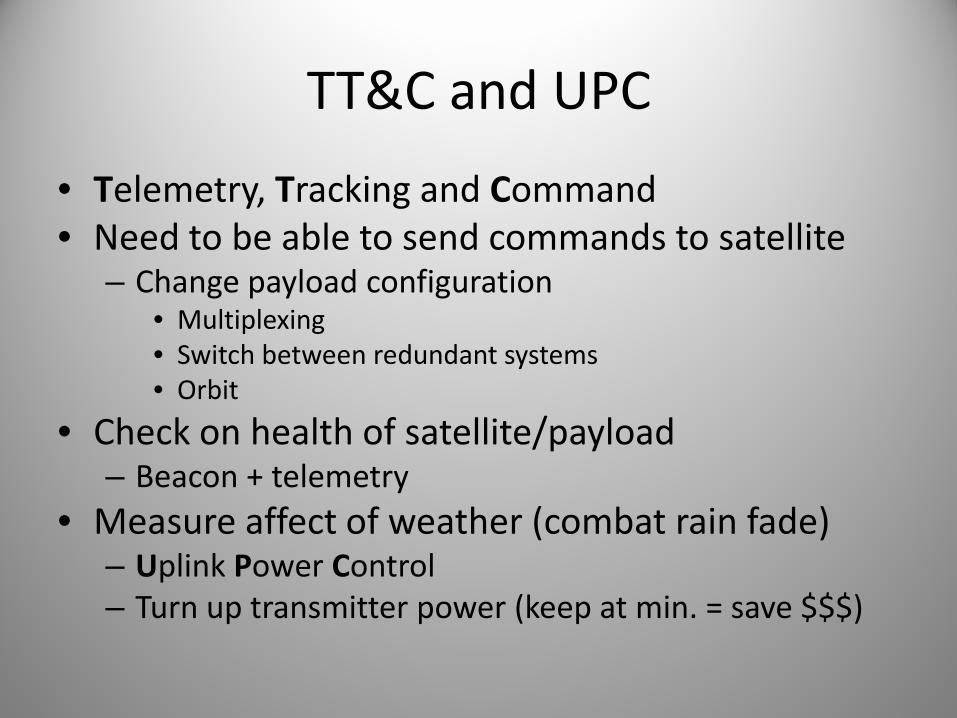
TT&C and UPC
• Telemetry, Tracking and Command• Need to be able to send commands to satellite
– Change payload configuration• Multiplexing• Switch between redundant systems• Orbit
• Check on health of satellite/payload– Beacon + telemetry
• Measure affect of weather (combat rain fade)– Uplink Power Control– Turn up transmitter power (keep at min. = save $$$)

Optus D1
• 24 Ku band transponders– Multiplexed spot beams service Aus and NZ
– Uplink: 14.0 ‐ 14.5 GHz
– Downlink: 12.25 ‐ 12.75 GHz
– Bandwidth: 54 MHz
• Mainly TV (wideband DVB‐S)– ABC, SBS, Se7en, Nin9, SkyNZ
• Some other (narrowband) things…

FNA Beam Coverage
Effective Isotropic Radiated Power (EIRP)

D1 Channel Frequencies
Uplink
Downlink
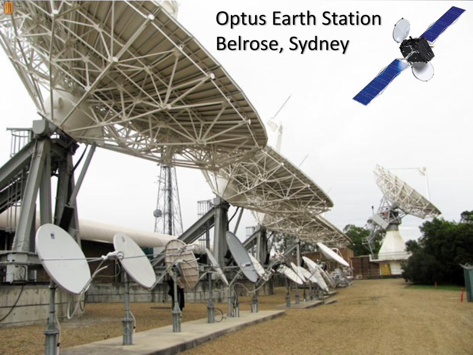
Optus Earth StationBelrose, Sydney


Spot the satellite modem
Radyne Comstream Satellite Modem DMD‐15

Digital Tracking Receiver
Antenna Control System
Redundant System Controller
C1 UPC

What you need
Dish + LNB + power injector + USRP + GNU Radio(set‐top box with LNB‐thru)

Low Noise Block down‐converter
Subtract 11.3 GHz from downlink frequency: 950 ‐ 1450 MHz


D1 TLM1: 12243.25 MHzMirror of RHS*
Beacon with Phase Modulation* (PM): 1PPS and two telemetry streams (sidebands)
Constant carrier power*
TLM sidebands
Constant sub‐carrier
1PPS

Visualisation


PSK Debug Output

Data Streams
• All sorts of continuous streams of varying bandwidth
• Streams created by manipulating raw data to optimise for transmission over long distance
• Receiver must be able to lock on and decode

Modulation: pick your parameters
Support multiple data streams,drop‐and‐insert
Make data appear random(increase entropy of structured data)
Encode changes in data(receiver can be non‐coherent)
Protect integrity of data(corruption from noise on channel)
Turn binary into symbolsfor baseband RF(0/1 combinations of waves)
Create signal suitable for uplink
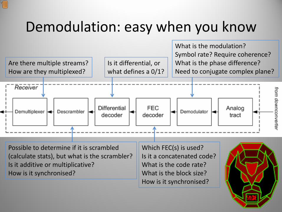
Demodulation: easy when you know
Are there multiple streams?How are they multiplexed?
Possible to determine if it is scrambled(calculate stats), but what is the scrambler?Is it additive or multiplicative?How is it synchronised?
Is it differential, or what defines a 0/1?
Which FEC(s) is used?Is it a concatenated code?What is the code rate?What is the block size?How is it synchronised?
What is the modulation?Symbol rate? Require coherence?What is the phase difference?Need to conjugate complex plane?

If you don’t know…
• Try the most common/default options (RTFMM):– Modulation: Phase Shift Keying (BPSK, QPSK)– Convolutional code: NASA, K=7 (Voyager Probe)– Scrambler: IESS‐803 (Intelsat Business Service)
• Still need to try each combination of:– Differential decoding, synchronisation offset, symbol mapping
• Best option is to try every permutation automatically
• Assuming decent SNR, low Bit Error Rate is an indicator you’re heading the right way!

Aside: PSK, Symbols & Bits
• PSK uses changes in phase of a signal (carrier) to convey data
• Demodulator detects phase changes and outputs symbols
• Order of PSK determines # bits in 1 symbol– Many bits/symbol thanks to imaginary numbers (I/Q)
• Raw bit rate = symbol rate x (# bits/symbol)– Binary PSK (BPSK): 1 bit/symbol– Quaternary PSK (QPSK): 2 bits/symbol– 8PSK: 3 bits/symbol, etc…

Determining modulation & rate
• Assuming PSK, easy to determine:– Modulation order: multiply the signal by itself
– Symbol rate: multiply the signal by a lagged version of itself (cyclostationary analysis)
• Only a few GR blocks required do this

Let’s try one…
• Feed entire baseband spectrum into GR• Perform ‘channel selection’ to isolate stream of interest (create new baseband
centred on stream)

Determine PSK order
• Start at 2 and go up
• Stop when spike appears

Determine PSK order
• Start at 2 and go up
• Stop when spike appears
QPSK: 2 bits/symbol

Determine Symbol Rate
• Find first peak
9.6 kHz = 9600 symbols/sec

Try synchronisation & FEC

Try synchronisation & FEC
FEC Rate: ½Not differentialNo phase shift(depends on when you switch on receiver)


Find Precise Symbol Rate


Creating Auto-FEC:sample_rate: 800000ber_threshold: 2048ber_smoothing: 0.01ber_duration: 8192ber_sample_decimation: 1settling_period: 4096pre_lock_duration: 8192
De-puncturer relative rate: 1.000000==> Using throttle at sample rate: 800000==> Using lock throttle rate: 50000Auto-FEC thread started: Thread-1Skipping initial samples while MPSK receiver locks: 4096
Reached excess BER limit: 11437.1352901 , locked: False , current puncture matrix: 0 , total samples received: 12289Applying lock value: 0
Beginning search...Applying rotation: 1j
Reached excess BER limit: 11870.4144919 , locked: False , current puncture matrix: 0 , total samples received: 24586Applying rotation: 1Applying conjugation: 0
Locking current XForm
=========================================================
FEC locked: 1/2=========================================================
Applying lock value: 1
Auto FEC


Demodulated & error‐corrected
• Symbol rate = 9600 symbols/sec
• Pre‐FEC raw bit rate = 19200 bits/sec
• Post‐FEC raw bit rate = 9600 bits/sec (½ rate)
• Visualise data: look for additional clues– Differential encoding
– Scrambling
– Structure

QPSK Phase Debug

Visualisation
• Raw data (0: black, 1: white)
Descrambling time!

De‐scrambled
• Better, but long runs of 0s and 1s (not ideal)
Differential decoding time!

Diff. decoded & de‐scrambled
• Structured, asynchronous packets of data!
Repeating structure

Pattern Search
• Search for repeating strings of bits
• Try to find frame header
• Clue: sudden increase in # of occurrences
Preceding 1s are just part of ‘idle’ stream when no data is being sent
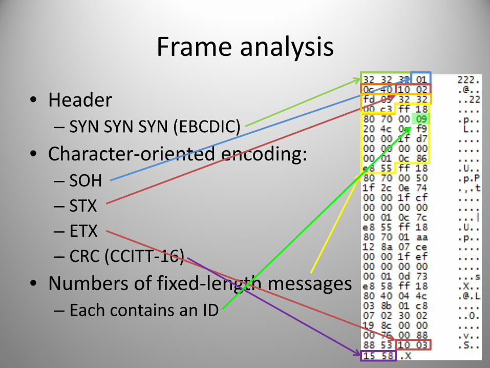
Frame analysis
• Header– SYN SYN SYN (EBCDIC)
• Character‐oriented encoding:– SOH– STX– ETX– CRC (CCITT‐16)
• Numbers of fixed‐length messages– Each contains an ID
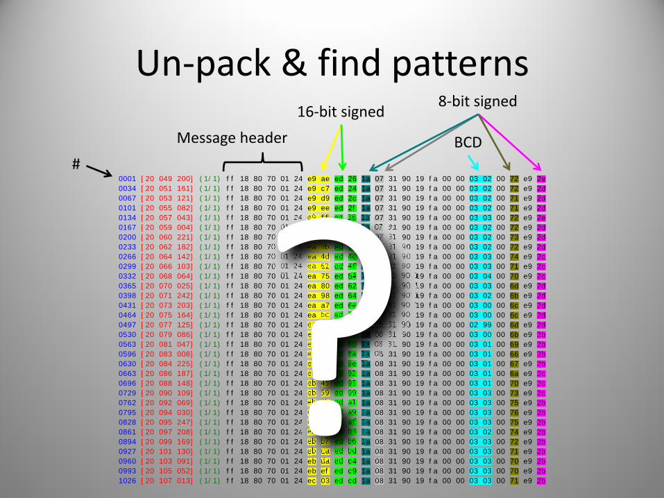
Un‐pack & find patterns
0001 [20 049 200] (1/1) ff 18 80 70 01 24 e9 ae ed 26 1a 07 31 90 19 fa 00 00 03 02 00 72 e9 2e
0034 [20 051 161] (1/1) ff 18 80 70 01 24 e9 c7 ed 24 1a 07 31 90 19 fa 00 00 03 02 00 72 e9 2d
0067 [20 053 121] (1/1) ff 18 80 70 01 24 e9 d9 ed 2c 1a 07 31 90 19 fa 00 00 03 02 00 71 e9 2d
0101 [20 055 082] (1/1) ff 18 80 70 01 24 e9 ee ed 2f 1a 07 31 90 19 fa 00 00 03 02 00 71 e9 2d
0134 [20 057 043] (1/1) ff 18 80 70 01 24 e9 ff ed 36 1a 07 31 90 19 fa 00 00 03 03 00 72 e9 2e
0167 [20 059 004] (1/1) ff 18 80 70 01 24 ea 10 ed 40 1a 07 31 90 19 fa 00 00 03 02 00 72 e9 2d
0200 [20 060 221] (1/1) ff 18 80 70 01 24 ea 24 ed 43 1a 07 31 90 19 fa 00 00 03 02 00 73 e9 2d
0233 [20 062 182] (1/1) ff 18 80 70 01 24 ea 3b ed 44 1a 07 31 90 19 fa 00 00 03 02 00 72 e9 2d
0266 [20 064 142] (1/1) ff 18 80 70 01 24 ea 4d ed 4c 1a 07 31 90 19 fa 00 00 03 03 00 74 e9 2c
0299 [20 066 103] (1/1) ff 18 80 70 01 24 ea 62 ed 4f 1a 07 31 90 19 fa 00 00 03 03 00 71 e9 2c
0332 [20 068 064] (1/1) ff 18 80 70 01 24 ea 75 ed 54 1a 07 31 90 19 fa 00 00 03 04 00 70 e9 2c
0365 [20 070 025] (1/1) ff 18 80 70 01 24 ea 80 ed 62 1a 07 31 90 19 fa 00 00 03 03 00 6d e9 2d
0398 [20 071 242] (1/1) ff 18 80 70 01 24 ea 98 ed 64 1a 07 31 90 19 fa 00 00 03 02 00 6b e9 2d
0431 [20 073 203] (1/1) ff 18 80 70 01 24 ea a7 ed 6e 1a 08 31 90 19 fa 00 00 03 00 00 6c e9 2d
0464 [20 075 164] (1/1) ff 18 80 70 01 24 ea bc ed 71 1a 08 31 90 19 fa 00 00 03 00 00 6c e9 2d
0497 [20 077 125] (1/1) ff 18 80 70 01 24 ea cf ed 76 1a 08 31 90 19 fa 00 00 02 99 00 6d e9 2d
0530 [20 079 086] (1/1) ff 18 80 70 01 24 ea e8 ed 76 1a 08 31 90 19 fa 00 00 03 00 00 6b e9 2b
0563 [20 081 047] (1/1) ff 18 80 70 01 24 ea f7 ed 80 1a 08 31 90 19 fa 00 00 03 01 00 69 e9 2b
0596 [20 083 008] (1/1) ff 18 80 70 01 24 eb 06 ed 8a 1a 08 31 90 19 fa 00 00 03 01 00 66 e9 2b
0630 [20 084 225] (1/1) ff 18 80 70 01 24 eb 1b ed 8e 1a 08 31 90 19 fa 00 00 03 01 00 67 e9 2b
0663 [20 086 187] (1/1) ff 18 80 70 01 24 eb 30 ed 92 1a 08 31 90 19 fa 00 00 03 01 00 6a e9 2c
0696 [20 088 148] (1/1) ff 18 80 70 01 24 eb 45 ed 95 1a 08 31 90 19 fa 00 00 03 01 00 70 e9 2c
0729 [20 090 109] (1/1) ff 18 80 70 01 24 eb 59 ed 99 1a 08 31 90 19 fa 00 00 03 03 00 73 e9 2c
0762 [20 092 069] (1/1) ff 18 80 70 01 24 eb 6b ed a1 1a 08 31 90 19 fa 00 00 03 03 00 75 e9 2b
0795 [20 094 030] (1/1) ff 18 80 70 01 24 eb 7b ed a9 1a 08 31 90 19 fa 00 00 03 03 00 76 e9 2b
0828 [20 095 247] (1/1) ff 18 80 70 01 24 eb 8e ed af 1a 08 31 90 19 fa 00 00 03 03 00 75 e9 2b
0861 [20 097 208] (1/1) ff 18 80 70 01 24 eb a2 ed b3 1a 08 31 90 19 fa 00 00 03 02 00 74 e9 2b
0894 [20 099 169] (1/1) ff 18 80 70 01 24 eb b7 ed b6 1a 08 31 90 19 fa 00 00 03 03 00 72 e9 2b
0927 [20 101 130] (1/1) ff 18 80 70 01 24 eb ca ed bd 1a 08 31 90 19 fa 00 00 03 03 00 71 e9 2b
0960 [20 103 091] (1/1) ff 18 80 70 01 24 eb da ed c4 1a 08 31 90 19 fa 00 00 03 03 00 70 e9 2b
0993 [20 105 052] (1/1) ff 18 80 70 01 24 eb ef ed c9 1a 08 31 90 19 fa 00 00 03 03 00 70 e9 2b
1026 [20 107 013] (1/1) ff 18 80 70 01 24 ec 03 ed cd 1a 08 31 90 19 fa 00 00 03 03 00 71 e9 2b
#
Message header
16‐bit signed
BCD
8‐bit signed

Graphing the Data
1540
1560
1580
1600
1620
1640
1660
‐980 ‐970 ‐960 ‐950 ‐940 ‐930 ‐920
‐8
‐6
‐4
‐2
0
2
4
6
0 5 10 15 20 25 30 35
0
20
40
60
80
100
120
0 5 10 15 20 25 30 35

Graphing the Data
4275
4280
4285
4290
4295
4300
4305
4310
4315
4320
‐1700 ‐1650 ‐1600 ‐1550 ‐1500 ‐1450 ‐1400 ‐1350
11.5
12
12.5
13
13.5
14
14.5
0 5 10 15 20 25 30 35
138
140
142
144
146
148
150
152
154
156
0 5 10 15 20 25 30 35

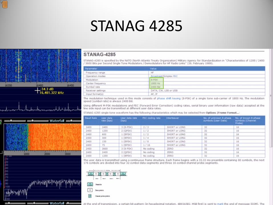
STANAG 4285

STANAG 4285
2400 baud

80 (preamble) +4 x 32 (data) +3 x 16 (channel probe)@ 2400 bps= 106.66 ms


DigitalRadioMondiale

Cyclic Autocorrelation Function
Un‐guarded symbol time
Total symbol periodicity
Han, Sohn & Moung,"A Blind OFDM Detection and Identification Method Based on Cyclostationarity for Cognitive Radio Application"

Un‐guarded Symbol Time
21.33 ms
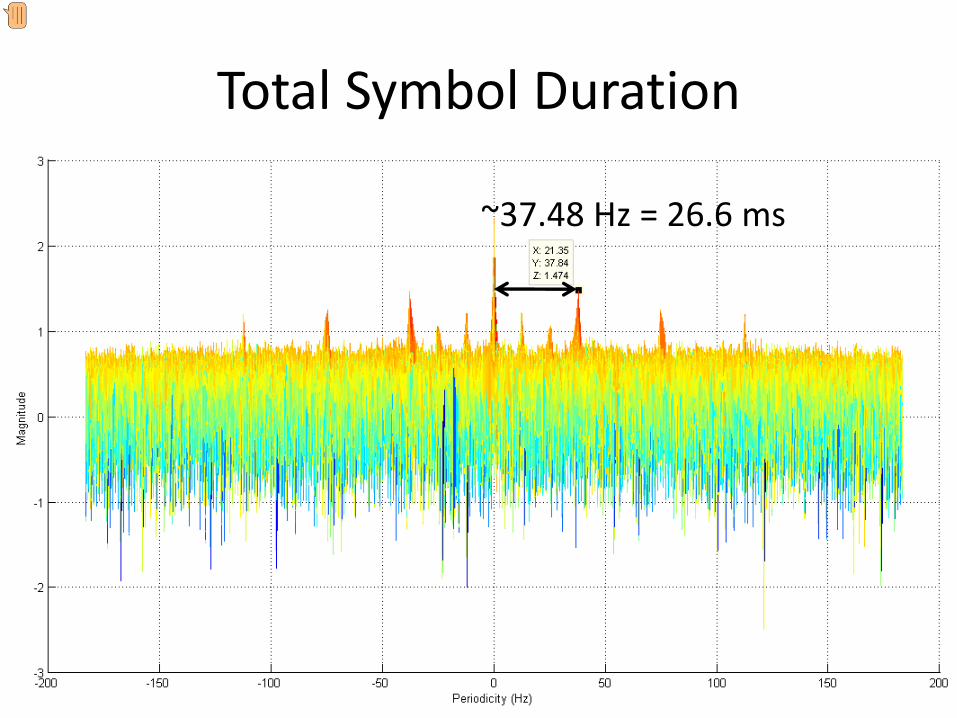
Total Symbol Duration
~37.48 Hz = 26.6 ms

Top‐down DRM Symmetry

DRM Class B
Modulation property Value
Un‐guarded symbol time 21.33 ms
Sub‐carrier spacing 46 7/8 Hz
Guard interval 5.33 ms
Total symbol duration 26.66 ms
Guard interval ratio 1/4
Symbols per frame 15
1 / (21.33 ms)


21.33 ms
(1 Msps / 50) x 21.33ms = 426.6

26.66 ms

“DUFF DUFF”Software DefinedRadio Direction Finding

DF Usage
• Radio navigation– Predecessor to RADAR
• SIGINT• Emergency aid
– Avalanche rescue
• Wildlife tracking• Reconnaissance
– Trajectory tracking
• Sport?!
Rotatableloop antenna

History
• WW I & II– Y‐stations along the British coastline
– Find bearing to U‐boats in Atlantic
– ‘U‐Adcock’ system• Four 10m high vertical aerials around hut
• DF goniometer (angle measurement) & radio

DF for HF
• HF: 3‐30 MHz– long wavelengths large distances
• HF/DF = “HUFF DUFF!”
• Used for SIGINT
• Large installations:AN/FLR‐9 array near Augsburg, Germany

Amateur RDF
• ‘Fox hunts’
• Competitor on ‘2‐meter band’ ARDF course
Highly‐directional Yagi antenna
Crazy‐serious German HAM

(Pseudo‐) Doppler DF
• Exploit Doppler shifting of radio waves caused by motion of an antenna
• Measure the shift in detected signalDetermine direction of transmission

Recap: Doppler Effect

Aside: Siren Misconception
“…the observed frequency increases as the object approaches an observer and then decreases only as the object passes the observer.”
“…Higher sound pressure levels make for a small decrease in perceived pitch in low frequency sounds, and for a small increase in perceived pitch for high frequency sounds.”

A Swan
DopplerEffect

Cosmological Redshift
Expansion of space, not motion of radiating object!

Frequency Modulation 101
Analog or digitalInformation to be transmitted
‘Main’ transmission frequency(e.g. 105.7 MHz)
Frequency modulation changes the carrier’s frequencyMoves the carrier slightly left/right of its original position on frequency plot

Physically Rotated Antenna
Joseph Moell,“Transmitter Hunting:Radio Direction Finding Simplified”,1987 (McGraw‐Hill)
Doppler Shift
• Doppler shift of received signal used to calculate angle of transmitter
• Easy with an FM radio!
• Frequency Modulation:– Shifts the centre (carrier) frequency about based on the original modulating signal
– Doppler shift just moves it around some more
• FM receiver detects Doppler as an extra tone!

Extra tone: sine wave
http://silcom.com/~pelican2/PicoDopp/ABOUT_DOPP.html

Mechanical Rotation Rate
• Doppler equation relates:– Doppler shift– Radius of antenna– Angular velocity (rotation rate)– Frequency of signal
• For a small antenna setup tuned to 2m wavelength (~150 MHz), requires:
38600 RPM~643 rot/sec

Pseudo‐Doppler
• Array of fixed antennas
• Switch electronically between them– ‘Simulate’ physical rotation

Electronically Rotated Antenna

Home‐made RDF
• ‘Roanoke Doppler’
• Four antennas
• Control box
• Plug in any standard FM radio
• LEDs indicate direction
Joseph Moell,“Transmitter Hunting:Radio Direction Finding Simplified”,1987 (McGraw‐Hill)

Block Diagram

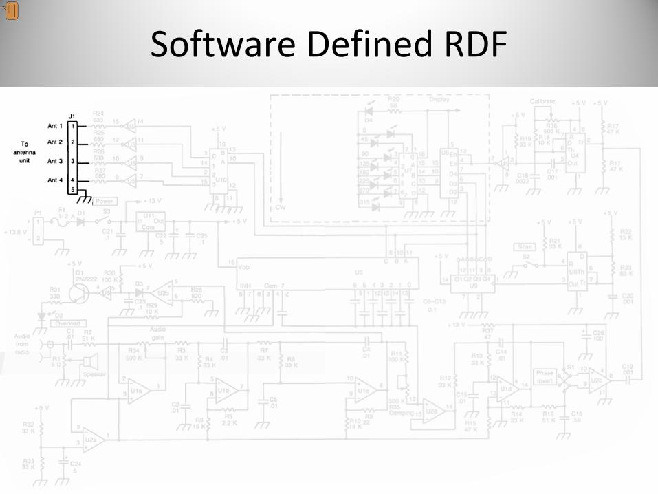
Circuit Diagram
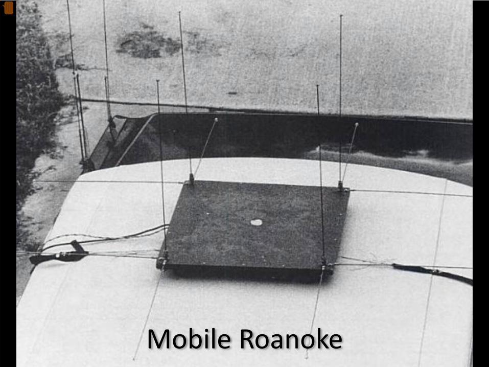
Mobile Roanoke

Time to go colour…

Software Defined RDF
Do it in software!
Software Defined RDF

Antenna Array

Antenna Switch
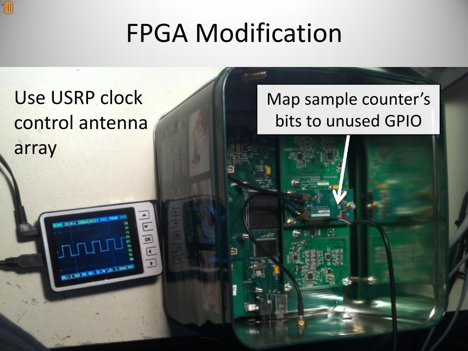
FPGA Modification
Use USRP clockcontrol antennaarray
Map sample counter’s bits to unused GPIO
Modification Bonuses
• Using FPGA clock ensures antenna switching is in lockstep with samples arriving at host– Same clock domain host‐side ‘just works’
– Use host‐generated sine wave as reference
• FPGA’s sample counter begins at zero for each stream start– Calibrate array orientation just once

Receiver

Processing & Display

Switching affecting spectrum

Signal Processing


Tricks
• Only need to know:1. Sample rate (FPGA clock / decimation)
2. Which bit of sample counter is MSB of switch
(64 MHz / 256) = 250 ksps
31st and 32nd bits used
250k / 32 = 7.8125 kHz tone
For Xlate decim 5 & 1024 FFT bins, tone sits in:
((250 ksps / 5) / 1024) * 7812.5 = 160 exactly


Magic of SDR
FM (quadrature) demodulation:Multiply current signal sample by complex conjugate of
previous one and find the argument (angle)
for (int i = 0; i < noutput_items; i++) {
gr_complex product = in[i] * conj(in[i-1]);
out[i] = d_gain * arg (product);
}
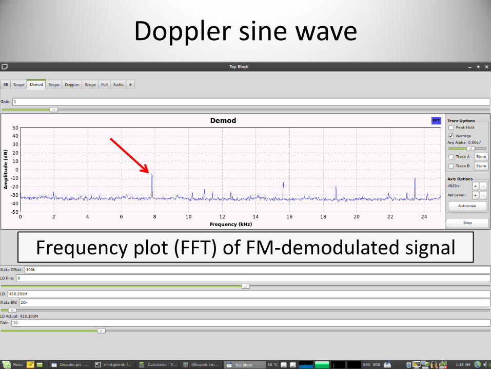
Doppler sine wave
Frequency plot (FFT) of FM‐demodulated signal

Doppler sine wave
Pure Doppler sine wave after filtering
Reference
Measured

Find a target

Telstra Tower on Council St


Known Transmitter

Start

Drive
Direction Measurement

Complications
• Line‐Of‐Sight– Beware of reflections
• Descending into ‘valley’…
– Reflections in urban areas
– Multiple wavefronts will ‘confuse’ FM detector• Doppler

Complications: Coogee
Line of sight

Listen: Multipath
Multiple reflections confusing FM detector
Inch forward until audio ‘clears up’
DC Phase (range) Strength

Done

Closer to (my new) home


Method 2: Super‐resolution algorithms
• Simultaneously receive multiple streams– One stream per antenna antenna array
• Apply a mathematical model– Linear (far‐field) wavefront approaching antenna array– Model/calibrate for antenna response
• MUSIC: MUltiple SIgnal Classification– Sample signal at each antenna (assuming sinusoids)– Maths (sample correlation matrix, eigenvector decomposition, orthogonal signal/noise subspaces)
– Search through array response to find peak DOA

Wavefront impinging on antenna array

Find maximal array response
Advantages
• Much higher resolution– Assuming model is correct & system is calibrated
• Detect & process multiple signals of interest simultaneously!
• However…you need more (coherent) radios.


GNU Radio MUSIC DOA block

Calibration
• Use shared Local Oscillator
• Inject shared tone in each channel
• Calculate per‐channel phase differences– w. r. t. reference channel
• Apply corrections
• Periodically re‐calibrate


Flowgraph


Police Checklist
• Car’s rego paper
• Amateur Radio licence
• Antenna structural redundancy
• Dress code
• Clean‐shaven
• Hide Motorola XTS radios
• Avoid turning around and trying to desperately disconnect antennas

Gedanken: TX
DO NOT TRY THIS AT…
WHEREVER!

Gedanken: Pagers
• Don’t like a doctor/nurse?
– Send them on many a wild goose chase
• Is your arch‐nemesis in hospital?
– Tell them to remove the other ********
• Need to distract security?
– Issue an ‘automated’ alert

Gedanken: Mode S
• Want to reach cruising altitude a little quicker?
– Put a ‘plane’ heading towards you (at a slightly lower altitude)
• Think the pilot made the wrong choice in deciding to land?
– Put a ‘plane’ on the runway
• Want to display a message on everyone’s radar screen?
– Spell one using ‘aircraft marker’ art

Gedanken: ACARS
• Don’t want to fly on a particular aircraft?
– Send a severe fault report
• Was the flight a little bumpy?
– Send an engine performance report to RR with large vibration values
• Need to message the cockpit privately?
– Address the message to cockpit printer #1

Gedanken: Satellite
• Uplink power is generally kept at the minimum level to save money
• Depends on the weather:
– Clear sky: a few W
– Heavy rain: a few kW
• Turn yours up to (theirs + 1)
• “…a malfunctioning UPC system can interfere with other services and even damage a satellite Travelling Wave Tube Amplifier…”

Remember: be legal and be….