Embed Size (px)
Citation preview

© 2
012
Mer
cury
Mar
ine
Axiu
s &
Axiu
s Se
aCor
e 49
6 M
odel
s *87
928832
1*90
-879
2883
21 2
10NOTE: The following applies to CE marked products only.
Declaration of Conformity – Mercury MerCruiserThis sterndrive or inboard engine when installed in accordance to Mercury MerCruiser's instructions complies with therequirements of the following directives by meeting the associated standards, as amended:
Recreational Craft Propulsion Engines with the Requirements of Directive 94/25/EC as amended by 2003/44/EC
Name of engine manufacturer: Mercury Marine MerCruiserAddress: 3003 N. Perkins RoadTown: Stillwater, OK Post Code: 74075 Country: USA
Name of Authorized Representative: Brunswick Marine in EMEA Inc.Address: Parc Industriel de Petit‑RechainTown: Verviers Post Code: 4800 Country: Belgium
Name of Notified Body for exhaust emission assessment: Det Norske Veritas ASAddress: Veritasveien 1Town: Hovik Post Code: 1322 Country: Norway ID Number: 0575
Conformity assessment module used for exhaustemissions: ☐ B+C ☐ B+D ☐ B+E ☐ B+F ☐ G ☒ H
or engine type approved according to: ☐ stage II of Directive 97/68/EC ☐ Directive 88/77/ECConformity assessment module used for noise emissions: A ☐ Aa ☐ G ☐ H ☒Other Community Directives applied: Electromagnetic Compatibility Directive 2004/108/EC
Description of Engines and Essential Requirements
Engine Type Fuel Type Combustion Cycle☒ z or sterndrive with integral exhaust ☐ Diesel ☐ 2 stroke☐ Inboard engine ☒ Petrol ☒ 4 stroke

Identification of Engines Covered by This Declaration of Conformity
Name of engine family Unique engine identification number: starting serial number EC Module H certificate number
Vazer 100 1A035000 RCD‑H‑14.3 MPI OW319169 RCD‑H‑1SeaCore 4.3 0W319169 RCD‑H‑15.0 MPI 0W319169 RCD‑H‑1SeaCore 5.0 0W319169 RCD‑H‑1350 MAG 0W319169 RCD‑H‑1SeaCore 350 MAG 0W319169 RCD‑H‑1377 MAG 0W319169 RCD‑H‑1SeaCore 377 MAG 0W319169 RCD‑H‑1496 MAG 0W319169 RCD‑H‑1SeaCore 496 MAG 0W319169 RCD‑H‑1496 MAG HO 0W319169 RCD‑H‑1SeaCore 496 MAG HO 0W319169 RCD‑H‑1Axius 5.0 1A082379 RCD‑H‑1Axius 350 MAG 1A082379 RCD‑H‑1Axius 496 MAG 1A077727 RCD‑H‑1Axius 496 MAG HO 1A077727 RCD‑H‑1Axius SeaCore 5.0 1A082379 RCD‑H‑1Axius SeaCore 350 MAG 1A082379 RCD‑H‑1Axius SeaCore 496 MAG 1A077727 RCD‑H‑1Axius SeaCore 496 MAG HO 1A077727 RCD‑H‑1
Essential requirements standards other normative document/method technical file Please specify in more detail
(* = mandatory standard)
Annex 1.B—Exhaust EmissionsB.1 engine identification ☐ ☐ ☒
B.2 exhaust emission requirements ☒* ☐ ☐ *EN ISO 8178‑1:1996
B.3 durability ☐ ☐ ☒
B.4 owner's manual ☒ ☐ ☐ ISO 8665: 1995
Annex 1.C—Noise EmissionsC.1 Noise emission levels ☒* ☐ ☐ *EN ISO 14509
C.2 Owner's Manual ☐ ☒ ☐ Owner's Manual
This declaration of conformity is issued under the sole responsibility of the manufacturer. I declare on behalf of the enginemanufacturer that the engine(s) mentioned above complies (comply) with all applicable essential requirements in the wayspecified.
Name / function:Mark Schwabero, President, MercuryMarine
Signature and title:
Date and place of issue: July 24, 2008Stillwater, Oklahoma, USA
Regulatory contact:Regulations and Product Safety DepartmentMercury MarineW6250 W. Pioneer RoadFond du Lac, WI 54936USA
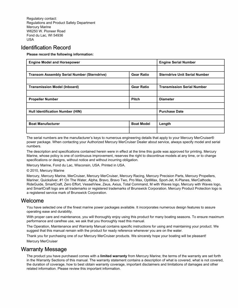
Identification RecordPlease record the following information:
Engine Model and Horsepower Engine Serial Number
Transom Assembly Serial Number (Sterndrive) Gear Ratio Sterndrive Unit Serial Number
Transmission Model (Inboard) Gear Ratio Transmission Serial Number
Propeller Number Pitch Diameter
Hull Identification Number (HIN) Purchase Date
Boat Manufacturer Boat Model Length
The serial numbers are the manufacturer’s keys to numerous engineering details that apply to your Mercury MerCruiser®power package. When contacting your Authorized Mercury MerCruiser Dealer about service, always specify model and serialnumbers.The description and specifications contained herein were in effect at the time this guide was approved for printing. MercuryMarine, whose policy is one of continuous improvement, reserves the right to discontinue models at any time, or to changespecifications or designs, without notice and without incurring obligation.Mercury Marine, Fond du Lac, Wisconsin, USA. Printed in USA.© 2010, Mercury MarineMercury, Mercury Marine, MerCruiser, Mercury MerCruiser, Mercury Racing, Mercury Precision Parts, Mercury Propellers,Mariner, Quicksilver, #1 On The Water, Alpha, Bravo, Bravo Two, Pro Max, OptiMax, Sport‑Jet, K‑Planes, MerCathode,RideGuide, SmartCraft, Zero Effort, VesselView, Zeus, Axius, Total Command, M with Waves logo, Mercury with Waves logo,and SmartCraft logo are all trademarks or registered trademarks of Brunswick Corporation. Mercury Product Protection logo isa registered service mark of Brunswick Corporation.
WelcomeYou have selected one of the finest marine power packages available. It incorporates numerous design features to assureoperating ease and durability.With proper care and maintenance, you will thoroughly enjoy using this product for many boating seasons. To ensure maximumperformance and carefree use, we ask that you thoroughly read this manual.The Operation, Maintenance and Warranty Manual contains specific instructions for using and maintaining your product. Wesuggest that this manual remain with the product for ready reference whenever you are on the water.Thank you for purchasing one of our Mercury MerCruiser products. We sincerely hope your boating will be pleasant!Mercury MerCruiser
Warranty MessageThe product you have purchased comes with a limited warranty from Mercury Marine; the terms of the warranty are set forthin the Warranty Sections of this manual. The warranty statement contains a description of what is covered, what is not covered,the duration of coverage, how to best obtain warranty coverage, important disclaimers and limitations of damages and otherrelated information. Please review this important information.
Mercury Marine products are designed and manufactured to comply with our own high quality standards, applicable industrystandards and regulations, as well as certain emissions regulations. At Mercury Marine every engine is operated and testedbefore it is boxed for shipment to make sure that the product is ready for use. In addition, certain Mercury Marine products aretested in a controlled and monitored environment, for up to 10 hours of engine run time, in order to verify and make a record ofcompliance with applicable standards and regulations. All Mercury Marine product, sold as new, receives the applicable limitedwarranty coverage, whether the engine participated in one of the test programs described above or not.
Read This Manual ThoroughlyIMPORTANT: If you do not understand any portion of this manual, contact your dealer for a demonstration of actual startingand operating procedures.
NoticeThroughout this publication, and on your power package, dangers, warnings, cautions, and notices, accompanied by the
International Hazard Symbol ! , may be used to alert the installer/user to special instructions concerning a particular serviceor operation that may be hazardous if performed incorrectly or carelessly. Observe them carefully.These Safety Alerts alone cannot eliminate the hazards that they signal. Strict compliance with these special instructions whileperforming the service, plus common sense operation, are major accident prevention measures.
! DANGERIndicates a hazardous situation which, if not avoided, will result in death or serious injury.
! WARNINGIndicates a hazardous situation which, if not avoided, could result in death or serious injury.
! CAUTIONIndicates a hazardous situation which, if not avoided, could result in minor or moderate injury.
NOTICEIndicates a situation which, if not avoided, could result in engine or major component failure.
IMPORTANT: Identifies information essential to the successful completion of the task.NOTE: Indicates information that helps in the understanding of a particular step or action.
! WARNINGThe operator (driver) is responsible for the correct and safe operation of the boat, the equipment aboard and the safety of alloccupants aboard. We strongly recommend that the operator read this Operation, Maintenance and Warranty Manual andthoroughly understand the operational instructions for the power package and all related accessories before the boat is used.
! WARNINGThe engine exhaust from this product contains chemicals known to the state of California to cause cancer, birth defects orother reproductive harm.

90-879288321 eng FEBRUARY 2010 Page i
TABLE OF CONTENTS
Section 1 - Warranty
Warranty Registration: United States and Canada.................... 2Warranty Registration: Outside the United States andCanada...................................................................................... 2Transfer of Warranty.................................................................. 2Mercury Installation Quality Certification Program..................... 3Mercury Product Protection Plan: United States and Canada... 4Mercury MerCruiser Limited Warranty (Gasoline‑FueledProducts Only) .......................................................................... 43‑Year Limited Warranty Against Corrosion.............................. 64‑Year Limited Corrosion Warranty: SeaCore Sterndrive Modelswith Gas Engines ...................................................................... 7
Global Application Warranty Charts........................................... 9Warranty for Consumer Applications.................................. 9Warranty for Commercial Applications............................... 9Warranty for Government Applications............................. 10
Emission Control Information Label......................................... 10Owner Responsibility..........................................................11
Emission Certification Star Label............................................. 12Hang Tag................................................................................. 13
Section 2 - Getting to Know Your Power Package
Identification............................................................................. 16Engine Serial Number Decal............................................ 16Bravo Sterndrive Serial Number and Identification........... 16Bravo Transom Serial Number......................................... 17
Features and Controls............................................................. 17Lanyard Stop Switch......................................................... 17Emergency Stop (E‑Stop) Switch..................................... 18Instrumentation................................................................. 18
VesselView (If Equipped)............................................. 18SC1000 and SC100 Digital Gauges (If Equipped)....... 19SmartCraft Partner Digital Gauges............................... 19Analog Gauges (If Equipped)....................................... 19
Bravo Sterndrive Serial Number and Identification........... 20Electronic Helm Steering.................................................. 21Dual‑Handle Electronic Remote Control (ERC) with DTSTrackpad Features and Operation.................................... 21
Operation...................................................................... 21
Adjustment....................................................................21Joystick—Basic Operation................................................ 22Power Trim....................................................................... 22
ERC Trim Control......................................................... 22Joystick and Trim Control............................................. 23Trailer and Trailer Limit Position................................... 23
Trim without Key............................................................... 24Electrical System Overload Protection............................. 24Audio Warning System..................................................... 26
Caution......................................................................... 26Severe.......................................................................... 26OBDM (On‑Board Diagnostics Marine)........................ 27OBDM Malfunction Indicator Lamp (MIL)..................... 27Testing the Audio Warning System.............................. 28
Guardian Strategy............................................................. 28Axius Premier Features (If equipped)...................................... 28
Axius Premier Precision Pilot Trackpad Functions........... 28
Section 3 - On the Water
Safe Boating Suggestions........................................................ 32Carbon Monoxide Exposure.................................................... 33
Be Alert To Carbon Monoxide Poisoning........................... 33Stay Clear of Exhaust Areas.............................................. 33Good Ventilation ................................................................ 33Poor Ventilation ................................................................. 34
Basic Boat Operation............................................................... 34Trailering the Boat............................................................ 34Freezing Temperature Operation..................................... 34Drain Plug and Bilge Pump............................................... 34
Protecting People in the Water................................................ 34While You Are Cruising...................................................... 34While Boat Is Stationary..................................................... 35
High‑Speed and High‑Performance Operation........................ 35Passenger Safety in Pontoon Boats and Deck Boats.............. 35
Boats Having an Open Front Deck.....................................35Boats With Front‑Mounted, Raised Pedestal Fishing Seats........................................................................................... 35
Wave and Wake Jumping........................................................ 36
Impact with Underwater Hazards............................................. 36Drive Unit Impact Protection...............................................37
Operating with Low Water Inlets in Shallow Water.................. 37Conditions Affecting Operation................................................ 37
Weight Distribution (Passengers and Gear) Inside theBoat.................................................................................. 37The Bottom of the Boat..................................................... 37Cavitation.......................................................................... 38Ventilation......................................................................... 38Elevation and Climate....................................................... 38Propeller Selection............................................................ 38
Getting Started......................................................................... 3820‑Hour Break‑In Period................................................... 38Launching and Boat Operation......................................... 39
Operation Chart............................................................ 39Starting and Stopping the Engine..................................... 39
Starting the Engine....................................................... 39Stopping the Engine..................................................... 40
Throttle Only Operation.................................................... 40

Page ii 90-879288321 eng FEBRUARY 2010
Traditional Maneuvering with Steering and Thrust.......... 41To Maneuver the Boat in Forward...............................41To Steer the Boat in Tight Turns at Low Speeds........ 41To Spin the Boat at Low Speeds................................ 41
Maneuvering with the Joystick........................................ 41Special Digital Throttle and Shift (DTS) Features........... 45
Dock............................................................................ 46Throttle Only................................................................471 (Single) Lever........................................................... 47Sync............................................................................ 48
After Break‑In Period....................................................... 48End of First Season Checkup.......................................... 48
Axius Premier (If equipped).................................................... 48Axius Premier Touchpad ................................................ 48
General Information.................................................... 48Heading Adjustment and Override.............................. 49Standby....................................................................... 49Standby and Active Lights...........................................49Power Icon.................................................................. 49Auto Heading.............................................................. 50
Disengage Auto Heading............................................ 53To Resume to a Heading ........................................... 53Changing VesselView Mode Display Times................54
Skyhook........................................................................... 54Engaging (Activating) Skyhook................................... 55The Skyhook Screen in VesselView........................... 56Disengaging (Deactivating) Skyhook.......................... 57
Response Button............................................................. 57Track Waypoint............................................................... 58
Engaging Track Waypoint Mode................................. 58Disengaging Track Waypoint Mode............................ 59Turn Buttons or Joystick in Track Waypoint Mode...... 59Auto Heading Button in Track Waypoint Mode .......... 59Acknowledging a Turn During a Waypoint Arrival....... 59Waypoint Sequence.................................................... 61
Cruise Control................................................................. 63Contingent Operations............................................................ 63
Port Engine–Only Operation............................................ 63Axius Shift Override—Emergency Procedure................. 64
Section 4 - Specifications
Fuel Requirements................................................................. 66Fuel Ratings...................................................................... 66Using Reformulated (Oxygenated) Gasolines (USA Only).......................................................................................... 66Gasolines Containing Alcohol........................................... 66
Engine Oil............................................................................... 66Engine Specifications............................................................. 67
Axius and Axius SeaCore 496 MAG, 496 MAG HO........ 67Fluid Specifications................................................................. 68
Engine............................................................................. 68Sterndrive—Bravo........................................................... 68Steering........................................................................... 68Power Trim...................................................................... 68
Section 5 - Maintenance
Owner/Operator Responsibilities............................................ 72Dealer Responsibilities........................................................... 72Maintenance........................................................................... 72Do‑It‑Yourself Maintenance Suggestions............................... 72Inspection............................................................................... 73Maintenance Schedules—Axius Models................................ 73
Routine Maintenance—Axius Models............................. 73Scheduled Maintenance—Axius Models......................... 73
Maintenance Log.................................................................... 74Engine Oil............................................................................... 75
Checking......................................................................... 75Filling............................................................................... 76Changing Oil and Filter.................................................... 76Engine Oil Drain Pump.................................................... 77Changing Filter................................................................ 77
Steering Fluid......................................................................... 78Checking and Filling Steering Fluid................................. 78Changing Steering Fluid.................................................. 78
Closed Cooling System.......................................................... 78Coolant Requirement...................................................... 78Checking Coolant Level.................................................. 79
.................................................................................... 79Filling the Closed Cooling System................................... 79Draining........................................................................... 80Cleaning.......................................................................... 80
Sterndrive Gear Lube............................................................. 80Checking......................................................................... 80Filling............................................................................... 81
Changing......................................................................... 81Power Trim Fluid.................................................................... 83
Checking........................................................................... 83Filling................................................................................ 83Changing.......................................................................... 83
Battery.................................................................................... 83Multiple EFI Engine Battery Precautions......................... 84
Cleaning the Flame Arrestor................................................... 84Water‑Separating Fuel Filter ................................................. 85
GEN III Models................................................................ 86Removal...................................................................... 86Installation................................................................... 86
Lubrication.............................................................................. 87Electronic Shift Control (ESC) Shift Cable...................... 87Sterndrive Unit and Transom Assembly.......................... 87Sterndrive U‑Joint Shaft Splines and O‑Rings (SterndriveUnit Removed)................................................................ 88Engine Coupler................................................................ 88
Propellers............................................................................... 88Propeller Repair.............................................................. 88Bravo Three Propeller Removal...................................... 89Bravo Three Propeller Installation................................... 90
Serpentine Drive Belt.............................................................. 91Checking......................................................................... 91Replacing........................................................................ 92
Corrosion Protection............................................................... 93Corrosion Information...................................................... 93Maintaining Ground Circuit Continuity............................. 93

90-879288321 eng FEBRUARY 2010 Page iii
MerCathode System Battery Requirements..................... 93Anodes and MerCathode System Locations.................... 93Checking the Quicksilver MerCathode System................ 94Power Package Exterior Surfaces.................................... 95Boat Bottom Care............................................................. 95Antifouling Paint................................................................ 95Sterndrive Surface Care................................................... 97
Flushing the Seawater System—Sterndrive Models................ 97General Information—Bravo Sterndrive............................ 97
Flushing Attachments................................................... 98Sterndrive Water Pickups............................................. 98
Boat Out of the Water—Bravo Sterndrive......................... 98Boat in the Water—Bravo Sterndrive................................ 99Boat Out of the Water—Alternative Water Pickups........ 100Boat in the Water—Alternative Water Pickups............... 100SeaCore Power Package Flushing Procedure............... 101
Models Using The Sterndrive Water Pickup............... 101
Section 6 - Storage
Cold Weather or Extended Storage....................................... 106Preparing Power Package for Storage........................... 106
Engine and Fuel System Preparation......................... 106Draining the Seawater System.............................................. 107
Drain System Identification............................................. 107Air Actuated Single Point Drain System..................... 107Manual Drain System................................................. 108
Air Actuated Single Point Drain System......................... 108Boat in the Water........................................................ 108
Boat Out of the Water................................................. 110Manual Drain System..................................................... 111
Boat in the Water........................................................ 111Boat out of the Water..................................................111
Draining the Sterndrive................................................... 112Draining Water from the Gen III Cool Fuel Module................ 113Battery Storage...................................................................... 113Recommissioning the Power Package.................................. 113
Section 7 - Troubleshooting
Check VesselView First......................................................... 116Diagnosing EFI Problems...................................................... 116Diagnosing DTS Problems..................................................... 116Engine Guardian System....................................................... 116Troubleshooting Charts.......................................................... 116
Starter Motor Will Not Crank Engine, Or Cranks Slow... 116Engine Will Not Start or Is Hard to Start......................... 116Poor Performance........................................................... 117Engine Runs Rough, Misses, or Backfires..................... 117Excessive Engine Temperature...................................... 117
Insufficient Engine Temperature..................................... 117Low Engine Oil Pressure................................................ 118Battery Will Not Recharge.............................................. 118Joystick........................................................................... 118Electronic Remote Controls............................................ 118Steering System............................................................. 119Power Trim Does Not Operate (Motor Does Not Operate)119Power Trim Does Not Operate (Motor Operates butSterndrive Unit Does Not Move)..................................... 120
Section 8 - Customer Assistance Information
Owner Service Assistance..................................................... 122Local Repair Service........................................................ 122Service Away From Home................................................122Stolen Power Package..................................................... 122Attention Required after Submersion............................... 122Replacement Service Parts.............................................. 122
Parts and Accessories Inquiries................................. 122
Resolving a Problem........................................................ 122Mercury Marine Service Offices....................................... 123
Ordering Literature................................................................. 123United States and Canada............................................... 123Outside the United States and Canada............................ 124
Dealer Checklist and Customer Orientation........................... 124

Page iv 90-879288321 eng FEBRUARY 2010

Section 1 - Warranty
90-879288321 eng FEBRUARY 2010 Page 1
Section 1 - WarrantyTable of ContentsWarranty Registration: United States and Canada................. 2Warranty Registration: Outside the United States and Canada................................................................................................ 2Transfer of Warranty............................................................... 2Mercury Installation Quality Certification Program................. 3Mercury Product Protection Plan: United States and Canada................................................................................................ 4Mercury MerCruiser Limited Warranty (Gasoline‑FueledProducts Only) ....................................................................... 43‑Year Limited Warranty Against Corrosion........................... 6
4‑Year Limited Corrosion Warranty: SeaCore SterndriveModels with Gas Engines ...................................................... 7Global Application Warranty Charts....................................... 9
Warranty for Consumer Applications............................... 9Warranty for Commercial Applications............................ 9Warranty for Government Applications.......................... 10
Emission Control Information Label...................................... 10Owner Responsibility .................................................... 11
Emission Certification Star Label.......................................... 12Hang Tag.............................................................................. 13
1

Section 1 - Warranty
Page 2 90-879288321 eng FEBRUARY 2010
Warranty Registration: United States and CanadaTo ensure that your warranty coverage begins promptly, your selling dealer should fill out the Warranty Registration Cardcompletely and mail it to the factory immediately upon sale of the new product.The Warranty Registration Card identifies the name and address of the original purchaser, product model and serial number(s),date of sale, type of use and selling dealer’s code, name, and address. The dealer also certifies that you are the originalpurchaser and user of the product. A temporary Owner Warranty Registration Card will be presented to you when you purchasethe product.Upon receipt of the Warranty Registration Card at the factory, Mercury MerCruiser will send you an owner resource guide thatincludes your warranty registration confirmation. If you do not receive your owner resource guide within 60 days from date ofnew product sale, please contact your selling dealer.Because of your selling dealer’s ongoing interest in your satisfaction, the product should be returned to him for warrantyservice.The product warranty is not effective until the product is registered at the factory.NOTE: Registration lists must be maintained by the factory and dealer on marine products sold in the United States in the eventthat a safety recall notification under the Federal Boat Safety Act is required.You may change your address at any time, including at time of warranty claim, by calling Mercury MerCruiser or sending aletter or fax to Mercury MerCruiser’s warranty registration department with your name, old address, new address, and engineserial number. Your dealer can also process this change of information.United States customers or dealers may contact:Mercury MarineAttn: Warranty Registration DepartmentW6250 Pioneer RoadP.O. Box 1939Fond du Lac, WI 54936-1939920-929-5054Fax 920-929-5893Canadian customers or dealers may contact:Mercury Marine Canada Limited2395 Meadowpine Blvd.Mississauga,Canada, L5N 7W6Fax 1-800-663-8334
Warranty Registration: Outside the United States and CanadaTo ensure that your warranty coverage begins promptly, your selling dealer should fill out the warranty registration cardcompletely and mail it to the distributor responsible for administering the warranty registration and claim program for your area.The warranty registration card identifies your name and address, product model and serial numbers, date of sale, type of use,and the selling distributor’s and dealer’s code number, name, and address. The distributor or dealer also certifies that you arethe original purchaser and user of the product. A copy of the warranty registration card, designated as the purchaser’s copy,MUST be given to you immediately after the card has been completely filled out by the selling distributor or dealer. This cardrepresents your factory registration identification. Keep the card; if you ever need warranty service on this product, your dealermay ask you for the warranty registration card to verify date of purchase and to use the information on the card to prepare thewarranty claim forms.In some countries, the distributor will issue a permanent (plastic) warranty registration card to you within 30 days after receivingthe factory copy of the warranty registration card from your distributor or dealer. If you receive a plastic warranty registrationcard, you may discard the purchaser’s copy that you received from the distributor or dealer when you purchased the product.Ask your distributor or dealer if this plastic card program applies to you. For further information concerning the warrantyregistration card and its relationship to warranty claim processing, refer to the International Warranty. See Table of Contents.NOTE: Registration lists must be maintained by the factory and dealer on marine products sold in the United States in the eventof a safety recall notification under the Federal Boat Safety Act.
Transfer of WarrantyThe limited warranty is transferable to a subsequent purchaser, but only for the remainder of the unused portion of the limitedwarranty. This will not apply to products used for commercial applications.To transfer the warranty to the subsequent owner, send or fax a copy of the bill of sale or purchase agreement, new owner’sname, address and engine serial number to Mercury Marine’s warranty registration department. In the United States mail to:

Section 1 - Warranty
90-879288321 eng FEBRUARY 2010 Page 3
Mercury MarineAttn: Warranty Registration DepartmentW6250 W. Pioneer RoadP.O. Box 1939Fond du Lac, WI 54936-1939920-929-5054Fax 920-929-5893In Canada mail to:Mercury Marine Canada Limited2395 Meadowpine Blvd.Mississauga,Canada, L5N 7W6Fax 1-800-663-8334Upon processing the transfer of warranty, Mercury Marine will send registration verification to the new owner of the product bymail.There is no charge for this service.For products purchased outside the United States and Canada, contact the distributor in your country, or the distributor closestto you.
Mercury Installation Quality Certification Program
15502
Mercury MerCruiser products installed by a Mercury Installation Quality Certified Manufacturer are Installation Quality certifiedproducts and may receive an additional one (1) year of limited warranty coverage.The Installation Quality Certification program was developed to recognize MerCruiser boatbuilder customers who haveachieved higher manufacturing standards. It is the first and only comprehensive manufacturer‑installation certification programin the industry.The program has three goals:1. To enhance overall product quality.2. To improve the boat ownership experience.3. To enhance overall customer satisfaction.The certification process is designed to review all facets of manufacturing and engine installation. The program is composed ofdesign, manufacturing and installation review stages with which builders must comply. Certification applies leading‑edgemethodologies to create:• Efficiencies and best practices specific to engine installation.• World‑class assembly and component specifications.• Efficient installation processes.• Industry standard end‑of‑line test procedures
Boat builders that successfully complete the program and meet all certification requirements earn Installation Quality SystemCertified Manufacturer status and receive an additional one (1) year of Mercury limited factory warranty coverage on allMerCruiser‑powered boats that are registered on and after the boat builder's certification date for all worldwide registrations.

Section 1 - Warranty
Page 4 90-879288321 eng FEBRUARY 2010
Mercury has designated a section of our Website to promote the Installation Quality Certification Program and communicate itsbenefits to consumers. For a current list of MerCruiser‑powered boat brands that have earned Installation Quality Certification,visit www.mercurymarine.com/mercruiser_warranty.
Mercury Product Protection Plan: United States and Canada(Certain performance products, triple engine installations, and commercial applications are excluded.)The Mercury Product Protection Plan provides coverage against unexpected mechanical and electrical breakdowns that mayoccur beyond the standard limited warranty.The optional Mercury Product Protection Plan is the only Factory Plan available for your engine.One‑, two‑, three‑, four‑, or five‑ year term plans can be purchased up to 12 months after the original engine registration date.See your participating Mercury MerCruiser dealer for complete program details.
Mercury MerCruiser Limited Warranty (Gasoline‑Fueled Products Only)Mercury MerCruiser Limited Warranty (Gasoline‑Fueled Products Only)What is CoveredMercury Marine warrants its new products to be free of defects in material and workmanship during the period describedfollowing.
Duration of CoverageWarranty Period for Recreational UseThe warranty period begins on the date the product is first sold to a recreational‑use retail purchaser or the date on whichthe product is first put into service, whichever occurs first. Products installed by an Installation Quality Certified Installerreceive one (1) year of additional warranty coverage. The repair or replacement of parts or the performance of service underthis warranty does not extend the life of this warranty beyond its original expiration date. The warranty period is specific tothe model covered; see your model for the base coverage period:
Coverage for Horizon Inboard Models, and Vazer 100 Sterndrive ModelsThe Limited Warranty for Horizon Inboard Models and Vazer 100 Models is four (4) years when installed by anInstallation Quality Certified Installer or three (3) years for non‑certified installations.Coverage for SeaCore Sterndrive ModelsThe Limited Warranty for SeaCore Sterndrive Models is four (4) years when installed by an Installation Quality CertifiedInstaller or three (3) years for non‑certified installations.Coverage for Tow Sports Inboard ModelsThe Limited Warranty for Tow Sports 5.7 TKS models is two (2) years when installed by an Installation Quality CertifiedInstaller or one (1) year for non‑certified installations.The Limited Warranty for all other Tow Sports Inboard models is three (3) years when installed by an InstallationQuality Certified Installer or two (2) years for non‑certified installations.Coverage for All Other ModelsThe Limited Warranty for all other Gasoline Sterndrive and Inboard models except those described above is two (2)years when installed by an Installation Quality Certified Installer or one (1) year for non‑certified installations.
Warranty Period for Commercial UseThe warranty period begins on the date the product is first sold to a commercial‑use retail purchaser or the date on whichthe product is first put into service, whichever occurs first. Commercial users of these products receive warranty coveragefor either one (1) year from the date of first retail sale or the accumulation of 500 hours of operation, whichever occurs first.Commercial use is defined as any work‑related or employment‑related use of the product, or any use of the product thatgenerates income for any part of the warranty period, even if the product is only occasionally used for such purposes. Therepair or replacement of parts or the performance of service under this warranty does not extend the life of this warrantybeyond its original expiration date.
Transfer of CoverageUnexpired warranty coverage can be transferred from one recreational‑use customer to a subsequent recreational‑use customerupon proper reregistration of the product. Unexpired warranty coverage cannot be transferred either to or from a commercial‑usecustomer.

Section 1 - Warranty
90-879288321 eng FEBRUARY 2010 Page 5
Termination of CoverageWarranty coverage is terminated for used product obtained in any of the following ways:• Repossession from a retail customer• Purchase at auction• Purchase from a salvage yard• Purchase from an insurance company that obtained the product as a result of an insurance claim
Conditions That Must Be Met in Order to Obtain Warranty CoverageWarranty coverage is available only to retail customers that purchase from a dealer authorized by Mercury Marine to distributethe product in the country in which the sale occurred, and then only after the pre‑delivery inspection process specified byMercury Marine is completed and documented. Warranty coverage becomes available upon proper registration of the product bythe authorized dealer. Inaccurate warranty registration information regarding recreational use or subsequent change of use fromrecreational to commercial (unless properly reregistered) may void the warranty at the sole discretion of Mercury Marine. Routinemaintenance must be performed according to the maintenance schedule in the Operation, Maintenance & Warranty manual inorder to obtain warranty coverage. Mercury Marine reserves the right to make any warranty coverage contingent upon proof ofproper maintenance.
What Mercury Marine Will DoMercury Marine's sole and exclusive obligation under this warranty is limited to, at our option, repairing a defective part, replacingsuch part or parts with new or Mercury Marine certified remanufactured parts, or refunding the purchase price of the MercuryMarine product. Mercury Marine reserves the right to improve or modify products from time to time without assuming anobligation to modify products previously manufactured.
How to Obtain Warranty CoverageThe customer must provide Mercury Marine with a reasonable opportunity to repair and reasonable access to the product forwarranty service. Warranty claims shall be made by delivering the product for inspection to a Mercury Marine dealer authorizedto service the product. If the purchaser cannot deliver the product to such a dealer, written notice must be given to MercuryMarine. Mercury Marine will then arrange for the inspection and any covered repair. The purchaser in that case shall pay for allrelated transportation charges and travel time. If the service provided is not covered by this warranty, the purchaser shall pay forall related labor and material and any other expenses associated with that service. The purchaser shall not, unless requested byMercury Marine, ship the product or parts of the product directly to Mercury Marine. Proof of registered ownership must bepresented to the dealer at the time warranty service is requested in order to obtain coverage.

Section 1 - Warranty
Page 6 90-879288321 eng FEBRUARY 2010
What Is Not CoveredThis limited warranty does not cover the following:• Routine maintenance items• Adjustments• Normal wear and tear• Damage caused by abuse• Abnormal use• Use of a propeller or gear ratio that does not allow the engine to run in its recommended RPM range (see the Operation,
Maintenance & Warranty manual)• Operation of the product in a manner inconsistent with the recommended operation and duty cycle section of the Operation,
Maintenance & Warranty manual• Neglect• Accident• Submersion• Improper installation (proper installation specifications and techniques are set forth in the installation instructions for the
product)• Improper service• Use of an accessory or part that was not manufactured or sold by Mercury Marine and that damages the Mercury product• Jet pump impellers and liners• Operation with fuels, oils, or lubricants that are not suitable for use with the product (see the Operation, Maintenance &
Warranty manual)• Alteration or removal of parts• Water entering the engine through the fuel intake, air intake, or exhaust system or damage to the product from insufficient
cooling water caused by blockage of the cooling system by a foreign body• Running the engine out of water• Mounting the engine too high on the transom• Operating the boat with the engine over trimmed
Use of the product for racing or other competitive activity, or operating with a racing‑type lower unit at any point, even by aprevious owner of the product, voids the warranty. Expenses related to haul‑out, launch, towing, storage, telephone, rental,inconvenience, slip fees, insurance coverage, loan payments, loss of time, loss of income, or any other type of incidental orconsequential damages are not covered by this warranty. Also, expenses associated with the removal or replacement of boatpartitions or other material in order to gain access to the product are not covered by this warranty. No individual or entity,including Mercury Marine authorized dealers, has been given authority by Mercury Marine to make any affirmation,representation, or warranty regarding the product, other than those contained in this limited warranty. If such affirmation,representation, or warranty is made, it shall not be enforceable against Mercury Marine.
DISCLAIMERS AND LIMITATIONSTHE IMPLIED WARRANTIES OF MERCHANTABILITY AND FITNESS FOR A PARTICULAR PURPOSE ARE EXPRESSLYDISCLAIMED. TO THE EXTENT THAT THEY CANNOT BE DISCLAIMED, THE IMPLIED WARRANTIES ARE LIMITED INDURATION TO THE LIFE OF THE EXPRESS WARRANTY. INCIDENTAL AND CONSEQUENTIAL DAMAGES AREEXCLUDED FROM COVERAGE UNDER THIS WARRANTY. SOME STATES/COUNTRIES DO NOT ALLOW FOR THEDISCLAIMERS, LIMITATIONS AND EXCLUSIONS IDENTIFIED ABOVE. AS A RESULT, THEY MAY NOT APPLY TO YOU.THIS WARRANTY GIVES YOU SPECIFIC LEGAL RIGHTS, AND YOU MAY ALSO HAVE OTHER LEGAL RIGHTS WHICHVARY FROM STATE TO STATE AND COUNTRY TO COUNTRY.
3‑Year Limited Warranty Against Corrosion3‑YEAR LIMITED WARRANTY AGAINST CORROSIONWhat Is Covered
Mercury Marine warrants that each new Mercury, Mariner, Mercury Racing, Sport Jet, M2 Jet Drive,Tracker by Mercury Marine Outboard, MerCruiser Inboard or Sterndrive engine (Product) will not berendered inoperative as a direct result of corrosion for the period of time described below.
Duration of Coverage

Section 1 - Warranty
90-879288321 eng FEBRUARY 2010 Page 7
This limited corrosion warranty provides coverage for three (3) years from either the date the product isfirst sold, or the date on which the product is first put into service, whichever occurs first. The repair andreplacement of parts, or the performance of service under this warranty does not extend the life of thiswarranty beyond its original expiration date. Unexpired warranty coverage can be transferred tosubsequent (noncommercial use) purchaser upon proper re‑registration of the product. Warrantycoverage is terminated for used product repossessed from a retail customer, purchased at auction, froma salvage yard, or from an insurance company that obtained the product as a result of an insuranceclaim.
Condition That Must Be Met in Order to Obtain Warranty CoverageWarranty coverage is available only to retail customers that purchase from a dealer authorized byMercury Marine to distribute the product in the country in which the sale occurred, and then only after theMercury Marine specified pre‑delivery inspection process is completed and documented. Warrantycoverage becomes available upon proper registration of the product by the authorized dealer. Corrosionprevention devices specified in the Operation, Maintenance & Warranty manual must be in use on theboat, and routine maintenance outlined in the Operation, Maintenance & Warranty manual must be timelyperformed (including without limitation the replacement of sacrificial anodes, use of specified lubricants,and touch‑up of nicks and scratches) in order to maintain warranty coverage. Mercury Marine reservesthe right to make warranty coverage contingent upon proof of proper maintenance.
What Mercury Will DoMercury's sole and exclusive obligation under this warranty is limited to, at our option, repairing acorroded part, replacing such part or parts with new or Mercury Marine certified re‑manufactured parts, orrefunding the purchase price of the Mercury product. Mercury reserves the right to improve or modifyproducts from time to time without assuming an obligation to modify products previously manufactured.
How to Obtain Warranty CoverageThe customer must provide Mercury with a reasonable opportunity to repair, and reasonable access tothe product for warranty service. Warranty claims shall be made by delivering the product for inspectionto a Mercury dealer authorized to service the product. If purchaser cannot deliver the product to such adealer, written notice must be given to Mercury. We will then arrange for the inspection and any coveredrepair. Purchaser in that case shall pay for all related transportation charges and/or travel time. If theservice provided is not covered by this warranty, purchaser shall pay for all related labor and material,and any other expenses associated with that service. Purchaser shall not, unless requested by Mercury,ship the product or parts of the product directly to Mercury. Proof of registered ownership must bepresented to the dealer at the time warranty service is requested in order to obtain coverage.
What Is Not CoveredThis limited warranty does not cover electrical system corrosion; corrosion resulting from damage,corrosion which causes purely cosmetic damage, abuse or improper service; corrosion to accessories,instruments, steering systems; corrosion to factory installed jet drive unit; damage due to marine growth;product sold with less than a one year limited Product warranty; replacement parts (parts purchased bythe Customer); products used in a commercial application. Commercial use is defined as any work oremployment related use of the product, or any use of the product which generates income, for any part ofwarranty period, even if the product is only occasionally used for such purposes.
4‑Year Limited Corrosion Warranty: SeaCore Sterndrive Models with GasEngines
4‑YEAR LIMITED CORROSION WARRANTY: SEACORE STERNDRIVE MODELS WITH GAS ENGINESWhat Is Covered
Mercury Marine warrants that each new MerCruiser SeaCore engine, transom, and sterndrive packagewill not be rendered inoperative as a direct result of corrosion for the period of time described below.
Duration of Coverage

Section 1 - Warranty
Page 8 90-879288321 eng FEBRUARY 2010
This limited corrosion warranty provides coverage for four (4) years from either the date on which theMerCruiser SeaCore engine, transom, and sterndrive package is first sold or the date on which it is firstput into service, whichever occurs first. The repair or replacement of parts or the performance of serviceunder this warranty does not extend the life of this warranty beyond its original expiration date. Unexpiredwarranty coverage can be transferred to a subsequent (noncommercial‑use) purchaser upon properreregistration of the product. Warranty coverage is terminated for used product obtained in any of thefollowing ways:• Repossession from a retail customer• Purchase at auction• Purchase from a salvage yard• Purchase from an insurance company that obtained the product as a result of an insurance claim
Condition That Must Be Met in Order to Obtain Warranty CoverageWarranty coverage is available only to retail customers that purchase from a dealer authorized byMercury Marine to distribute the product in the country in which the sale occurred, and then only after thepre‑delivery inspection process specified by Mercury Marine is completed and documented. Warrantycoverage becomes available upon proper registration of the product by the authorized dealer.Corrosion‑prevention devices specified in the Operation, Maintenance & Warranty manual must be in useon the boat, and routine maintenance outlined in the Operation, Maintenance & Warranty manual mustbe performed according to the maintenance schedule in the Operation, Maintenance & Warranty manual(including without limitation the replacement of sacrificial anodes, use of specified lubricants, andtouch‑up of nicks and scratches) in order to maintain warranty coverage. Mercury Marine reserves theright to make warranty coverage contingent upon proof of proper maintenance.
What Mercury Marine Will DoMercury's sole and exclusive obligation under this warranty is limited to, at our option, repairing acorroded part, replacing such part or parts with new or Mercury Marine certified remanufactured parts, orrefunding the purchase price of the Mercury product. Mercury reserves the right to improve or modifyproducts from time to time without assuming an obligation to modify products previously manufactured.
How to Obtain Warranty CoverageThe customer must provide Mercury Marine with a reasonable opportunity to repair and reasonableaccess to the product for warranty service. Warranty claims shall be made by delivering the product forinspection to a Mercury Marine dealer authorized to service the product. If the purchaser cannot deliverthe product to such a dealer, written notice must be given to Mercury Marine. Mercury Marine will thenarrange for the inspection and any covered repair. The purchaser in that case shall pay for all relatedtransportation charges and/or travel time. If the service provided is not covered by this warranty, thepurchaser shall pay for all related labor and material, and any other expenses associated with thatservice. The purchaser shall not, unless requested by Mercury Marine, ship the product or parts of theproduct directly to Mercury Marine. Proof of registered ownership must be presented to the dealer at thetime warranty service is requested in order to obtain coverage.
What Is Not CoveredThis limited warranty does not cover the following:• Electrical system corrosion• Corrosion resulting from damage• Corrosion that causes purely cosmetic damage• Abuse or improper service• Corrosion to accessories, instruments, and steering systems• Corrosion to a factory‑installed jet drive unit• Damage due to marine growth• Replacement parts (parts purchased by the customer)• Product sold with less than a one‑year limited product warranty• Products used in a commercial application. Commercial use is defined as any work or employment
related use of the product, or any use of the product which generates income, for any part ofwarranty period, even if the product is only occasionally used for such purposes.

Section 1 - Warranty
90-879288321 eng FEBRUARY 2010 Page 9
Global Application Warranty ChartsWarranty for Consumer Applications
Engine Model Region
Standard Factory Limited Warranty byCertification Status of Boat
ManufacturerConsumer
LimitedCorrosionWarrantyNot Certified Installation Quality
Certified
Axius SeaCore 496 MAGAxius SeaCore 496 MAG HO
The Americas (excluding Brazil) 3 years 4 years 4 years
Brazil 1 year 1 year 2 years
Europe, Middle East, Africa 3 years 4 years 4 years
Australia, New Zealand 3 years 3 years 4 years
Japan 1 year 1 year 1 year
South Pacific 2 years 2 years 2 years
Other Asia 1 year 1 year 1 year
Axius 496 MAGAxius 496 MAG HO
The Americas (excluding Brazil) 1 year 2 years 3 years
Brazil 2 years 2 years 2 years
Europe, Middle East, Africa 2 years 3 years 3 years
Australia, New Zealand 3 years 3 years 3 years
Japan 1 year 1 year 1 year
South Pacific 2 years 2 years 2 years
Other Asia 1 year 1 year 1 year
Warranty for Commercial Applications
Engine Model Region
Standard Factory Limited Warranty byCertification Status of Boat
ManufacturerCommercial
LimitedCorrosionWarrantyNot Certified Installation Quality
Certified
Axius SeaCore 496 MAGAxius SeaCore 496 MAGHOAxius 496 MAGAxius 496 MAG HO
The Americas (excluding Brazil) 1 year 1 year 1 year
Brazil 2 years 2 years 2 years
Europe, Middle East, Africa
1 year or 500hours 1 year or 500 hours 1 year or 500
hours
Australia, New Zealand
Japan
South Pacific
Other Asia

Section 1 - Warranty
Page 10 90-879288321 eng FEBRUARY 2010
Warranty for Government Applications
Engine Model Region
Standard Factory Limited Warranty byCertification Status of Boat
ManufacturerGovernment
Limited CorrosionWarranty
Not Certified Installation QualityCertified
Axius SeaCore 496 MAGAxius SeaCore 496 MAGHOAxius 496 MAGAxius 496 MAG HO
The Americas (excluding Brazil) 1 year 1 year 3 year
Brazil 2 years 2 years 2 years
Europe, Middle East, Africa
1 year or 500hours 1 year or 500 hours 1 year or 500
hours
Australia, New Zealand
Japan
South Pacific
Other Asia
Emission Control Information LabelA tamper‑resistant emission control information (ECI) label is affixed to the engine in a visible location at the time ofmanufacture by Mercury MerCruiser. Please note that the low emissions certification will not affect the fit, function, orperformance of the engine. Boatbuilders and dealers may not remove the label or the part it is affixed to before sale. Ifmodifications are necessary, contact Mercury MerCruiser about the availability of replacement decals before proceeding. Inaddition to the required emissions statement, the label lists the engine serial number, family, applicable emission standard, dateof manufacture (month, year), and engine displacement.
a - Applicable standardb - Engine serial numberc - Engine family named - Hydrocarbons plus oxides of nitrogen family
emission limite - Date of manufacturef - Engine displacement, engine powerg - Carbon monoxide family emission limit
IMPORTANT: A CE mark in the lower right corner of the Emission Control Information label indicates that an EU Declaration ofConformance applies. Refer to the front page of this manual for further information.IMPORTANT: Engines designated as exempt from either Federal EPA or California emission control regulations are notcovered by a separate emission control component warranty. The product's Mercury MerCruiser manufacturer's warranty is notaffected by the engine's designation under Federal EPA or California emission control regulations.
ECI Label Standard of Compliance
REFER TO THE OWNER'S MANUAL FOR MAINTENANCESPECIFICATIONS AND ADJUSTMENTS
FAMILY: XXXXXXXXXXXX
EMISSION CONTROL INFORMATIONNOT FOR SALE IN CALIFORNIA
THIS MARINE ENGINE COMPLIES WITH U.S. EPA EXHAUSTREGULATIONS FOR 2009
XXXXXXXXSERIAL #: DOM: MMM YYYY
DISP: X.XL
ECIE
PA
0575
43518CO FEL : XXX g/kWh
POWER XXX kW : HC+NOx FEL : XX.X g/kWh
Indicates a marine engine compliant with United States EPAexhaust emission regulations for 2009.This marine engine is not for sale in California.
REFER TO THE OWNER'S MANUAL FOR MAINTENANCESPECIFICATIONS AND ADJUSTMENTS
EMISSION CONTROL INFORMATION
THIS ENGINE CONFORMS TO 2009 CALIFORNIA AND U.S. EPAEMISSION REGULATIONS FOR SPARK IGNITION MARINE ENGINES
XXXXXXXXSERIAL #: DOM: MMM YYYY
DISP: X.XL
ECIE
PAC
A
0575HC+NOx FEL : XX.X g/kWhPOWER XXX kW :
CO FEL : XXX g/kWh
FAMILY: XXXXXXXXXXXX
43500
a
bc
d
ef
g

Section 1 - Warranty
90-879288321 eng FEBRUARY 2010 Page 11
ECI Label Standard of Compliance
REFER TO THE OWNER'S MANUAL FOR MAINTENANCESPECIFICATIONS AND ADJUSTMENTS
FAMILY: XXXXXXXXXXX
EMISSION CONTROL INFORMATION
THIS ENGINE CONFORMS TO 2009 CALIFORNIA EMISSIONREGULATIONS FOR SPARK IGNITION MARINE ENGINES
XXXXXXXXSERIAL #: DOM: MMM YYYY
DISP: X.XL
ECIC
AR
B
0575
43519CO FEL : XXX g/kWh
POWER XXX kW : HC+NOx FEL : XX.X g/kWh
Indicates a marine engine compliant with California CARBexhaust emission regulations for 2009
REFER TO THE OWNER'S MANUAL FOR MAINTENANCESPECIFICATIONS AND ADJUSTMENTS
EMISSION CONTROL INFORMATION
THIS ENGINE CONFORMS TO 2009 CALIFORNIA AND U.S. EPAEMISSION REGULATIONS FOR SPARK IGNITION MARINE ENGINES
XXXXXXXXSERIAL #: DOM: MMM YYYY
DISP: X.XL
ECIE
PAC
A
0575
43520HC+NOx FEL : XX.X g/kWh
POWER XXX kW : CO FEL : XXX g/kWh
FAMILY: XXXXXXXXXXXX
Indicates a marine engine compliant with California CARB andU.S. EPA regulations for 2009
REFER TO THE OWNER'S MANUAL FOR MAINTENANCESPECIFICATIONS AND ADJUSTMENTS
EMISSION CONTROL INFORMATIONNOT FOR SALE IN CALIFORNIA
THIS ENGINE IS EXEMPT UNDER 40 CFR 1068.255 FROMEMISSION STANDARDS AND RELATED REQUIREMENTS
XXXXXXXXSERIAL #: DOM: MMM YYYY
DISP: X.XL
ECIE
XEM
P
0575
43521
POWER XXX kW : CO FEL : XXX g/kWh
FAMILY: XXXXXXXXXXXX
HC+NOx FEL : XX.X g/kWh
Indicates a marine engine exempt under 40 CFR 1068.255 fromUnited States EPA exhaust emission regulations for 2010.This marine engine is not for sale in California.
EMISSION CONTROL INFORMATION
XXXXXXXXSERIAL #: DOM: MMM YYYYDISP: X.XL
ECIC
AR
BX
0575
43522
THIS ENGINE CONFORMS TO 2010 CALIFORNIA EMISSIONREGULATIONS FOR SPARK IGNITION MARINE ENGINES. THIS ENGINE IS EXEMPT UNDER 40 CFR 1068.255 FROM EMISSION STANDARDSAND RELATED REQUIREMENTS. REFER TO THE OWNERS MANUALFOR MAINTENANCE SPECIFICATIONS AND ADJUSTMENTS.
POWER XXX kW : CO FEL : XXX g/kWhHC+NOx FEL : XX.X g/kWh
FAMILY: XXXXXXXXXXXX
Indicates a marine engine compliant with 2010 Californiaemission regulations and exempt under 40 CFR 1068.255 fromUnited States EPA exhaust emission regulations
EMISSION CONTROL INFORMATION
ECIS
ERV
THIS ENGINE DOES NOT COMPLY WITH U.S. EPA NONROAD EMISSION REQUIREMENTS. SELLING OR INSTALLING THIS ENGINE FOR ANY PURPOSE OTHER THAN TO REPLACE A NONROAD ENGINE BUILTBEFORE JANUARY 1, 2010 MAY BE A VIOLATION OF FEDERAL LAW SUBJECT TO CIVIL PENALTY.
XXXXXXXXSERIAL #:
FAMILY: XXXXXXXXXXXXHC+NOx FEL : XX.X g/kWh
DISP: X.XL POWER XXX kW : CO FEL : XXX g/kWh 0575
43499
DOM: MMM YYYY
Indicates a service marine engine that can replace a marineengine built prior to January 1, 2010.
Owner ResponsibilityThe operator must have routine engine maintenance performed to maintain emission levels within prescribed certificationstandards.The operator may not modify the engine in any manner that alters the horsepower or allows emissions levels to exceed factoryspecifications.

Section 1 - Warranty
Page 12 90-879288321 eng FEBRUARY 2010
Emission Certification Star LabelYour boat is labeled on the hull with one of the following star labels. The Symbol for Cleaner Marine Engines Means:1. Cleaner Air and Water ‑ for a healthier lifestyle and environment.2. Better Fuel Economy ‑ burns up to 30‑40 percent less gas and oil than conventional carbureted two‑stroke engines, saving
money and resources.3. Longer Emission Warranty ‑ Protects consumer for worry free operation.Beginning January 1, 2003, one Three‑Star or Four‑Star label will be included with each factory‑certified Mercury MerCruiserengine.All Mercury MerCruiser engines (500 hp and below) will have a Three‑Star Ultra Low Emission rating or Four‑Star Super UltraLow Emission rating. The Star label identifies that these engines meet the California Air Resources Board's Sterndrive andInboard marine engine 2007 and later exhaust emission standards. Engines meeting these standards have 65‑90% loweremissions than One‑Star – Low Emissions engines.The Star label will be affixed on the left side of the hull as shown.
a - Recommended locationb - Secondary location
XX 1234 XX
32770
a b

Section 1 - Warranty
90-879288321 eng FEBRUARY 2010 Page 13
One Star ‑ Low emission
mc79569-1
The one‑star label identifies personal watercraft, outboard, sterndrive and inboardengines that meet the Air Resources Board's Personal Watercraft and Outboardmarine engine 2001 exhaust emission standards. Engines meeting these standardshave 75% lower emissions than conventional carbureted two‑stroke engines.These engines are equivalent to the U.S. EPA's 2006 standards for marineengines.
Two Stars ‑ Very Low emission
42145
The two‑star label identifies personal watercraft, outboard, sterndrive and inboardengines that meet the Air Resources Board's Personal Watercraft and Outboardmarine engine 2004 exhaust emission standards. Engines meeting these standardshave 20% lower emissions than One Star ‑ Low‑Emission engines.
Three Stars ‑ Ultra Low emission
42146
The three‑star label identifies engines that meet the Air Resources Board'sPersonal Watercraft and Outboard marine engine 2008 exhaust emissionstandards or the Sterndrive and Inboard marine engine 2003 exhaust emissionstandards. Engines meeting these standards have 65% lower emissions than OneStar ‑ Low Emission engines.
Four Stars ‑ Super Ultra Low emission
42155
The Four Star label identifies engines that meet the Air Resources Board'sSterndrive and Inboard marine engine 2009 exhaust emission standards. PersonalWatercraft and Outboard marine engines may also comply with these standards.Engines meeting these standards have 90% lower emissions than One Star ‑ LowEmission engines.
Hang TagThe dealer must mark the appropriate box on one hang tag to match the Star label affixed to the boat. The dealer is responsiblefor displaying the hang tag in a visible location on the boat on display in California. Failure to properly display the hang tagcould result in a citation and possible fine to the dealer from the California Air Resources Board.

Section 1 - Warranty
Page 14 90-879288321 eng FEBRUARY 2010
If in California, the dealer must place the hang tag in a visible location in the boat prior to displaying the boat.
43291
Hang tag front side Hang tag back side

Section 2 - Getting to Know Your Power Package
90-879288321 eng FEBRUARY 2010 Page 15
Section 2 - Getting to Know Your Power PackageTable of ContentsIdentification......................................................................... 16
Engine Serial Number Decal......................................... 16Bravo Sterndrive Serial Number and Identification........ 16Bravo Transom Serial Number...................................... 17
Features and Controls.......................................................... 17Lanyard Stop Switch...................................................... 17Emergency Stop (E‑Stop) Switch.................................. 18Instrumentation.............................................................. 18
VesselView (If Equipped) ...................................... 18SC1000 and SC100 Digital Gauges (If Equipped).............................................................................. 19SmartCraft Partner Digital Gauges ........................ 19Analog Gauges (If Equipped) ................................ 19
Bravo Sterndrive Serial Number and Identification........ 20Electronic Helm Steering............................................... 21Dual‑Handle Electronic Remote Control (ERC) with DTSTrackpad Features and Operation................................. 21
Operation ............................................................... 21
Adjustment ............................................................ 21Joystick—Basic Operation............................................. 22Power Trim.................................................................... 22
ERC Trim Control .................................................. 22Joystick and Trim Control ...................................... 23Trailer and Trailer Limit Position ............................ 23
Trim without Key............................................................ 24Electrical System Overload Protection.......................... 24Audio Warning System.................................................. 26
Caution .................................................................. 26Severe ................................................................... 26OBDM (On‑Board Diagnostics Marine) ................. 27OBDM Malfunction Indicator Lamp (MIL) .............. 27Testing the Audio Warning System ....................... 28
Guardian Strategy..........................................................28Axius Premier Features (If equipped)................................... 28
Axius Premier Precision Pilot Trackpad Functions........ 28
2

Section 2 - Getting to Know Your Power Package
Page 16 90-879288321 eng FEBRUARY 2010
IdentificationThe serial numbers are the manufacture's keys to numerous engineering details which apply to your MerCruiser powerpackage. When contacting MerCruiser about service, always specify model and serial numbers.
Engine Serial Number DecalThe serial number decal is located on top of the engine.
25902
Serial numbers and maintenance color codes decal
The engine serial number is also stamped in the engine block.
Bravo Sterndrive Serial Number and IdentificationThe Bravo sterndrive serial number, gear ratio, model number, and bar code are embedded in the ground plate on the port sideof the sterndrive.
33533
Bravo sterndrive information on ground plate
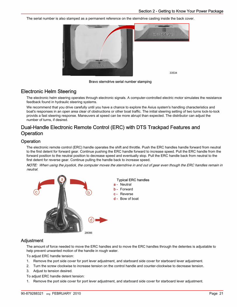
The serial number is also stamped as a permanent reference on the sterndrive casting inside the back cover.
33534
Bravo sterndrive serial number stamping

Section 2 - Getting to Know Your Power Package
90-879288321 eng FEBRUARY 2010 Page 17
Bravo Transom Serial NumberThe Bravo transom serial number is stamped in the U‑bolt plate of the Bravo transom assembly.
Bravo transom assembly U-bolt platea - Transom assembly serial Number
The serial number is also stamped on the gimbal housing. This is used as a permanent reference for authorized MerCruiserDealers.
Gimbal housing with serialnumber stamping
a - Transom assembly serialNumber
Features and ControlsLanyard Stop Switch
The purpose of a lanyard stop switch is to turn off the engine when the operator moves outside the operator's position (as inaccidental ejection from the operator's position).
a - Stop switchb - Lanyardc - Clips to the operator
Accidental ejections, such as falling overboard, are more likely to occur in:• low‑sided sport boats• bass boats• high performance boats
Accidental ejections can also occur from:
25904
a
25905
a
74608
RUN ab
c

Section 2 - Getting to Know Your Power Package
Page 18 90-879288321 eng FEBRUARY 2010
• poor operating practices• sitting on the seat or gunwale at planing speeds• standing at planing speeds• operating at planing speeds in shallow or obstacle infested waters• releasing your grip on the steering wheel that is pulling in one direction• consuming alcohol or drugs• high speed boating maneuvers
The lanyard is a cord usually between 122 and 152 cm (4 and 5 ft) in length when stretched out, with an element on one endmade to be inserted into the switch and a snap on the other end for attaching to the operator. The lanyard is coiled to make itsat‑rest condition as short as possible to minimize the likelihood of lanyard entanglement with nearby objects. Its stretched‑outlength is made to minimize the likelihood of accidental activation should the operator choose to move around in an area closeto the normal operator's position. If it is desired to have a shorter lanyard, wrap the lanyard around the operator's wrist or leg, ortie a knot in the lanyard.Activation of the lanyard stop switch will stop the engine immediately, but the boat will continue to coast for some distancedepending upon the velocity and degree of any turn at shut down. However, the boat will not complete a full circle. While theboat is coasting, it can cause injury to anyone in the boat's path as seriously as the boat would when under power.We strongly recommend that other occupants be instructed on proper starting and operating procedures should they berequired to operate the engine in an emergency (e.g. if the operator is accidentally ejected).
! WARNINGIf the operator falls out of the boat, stop the engine immediately to reduce the possibility of serious injury or death from beingstruck by the boat. Always properly connect the operator to the stop switch using a lanyard.
Accidental or unintended activation of the switch during normal operation is also a possibility. This could cause any, or all, ofthe following potentially hazardous situations:• Occupants could be thrown forward due to unexpected loss of forward motion, a particular concern for passengers in the
front of the boat who could be ejected over the bow and possibly struck by the propulsion or steering components.• Loss of power and directional control in heavy seas, strong current or high winds.• Loss of control when docking.
! WARNINGAvoid serious injury or death from deceleration forces resulting from accidental or unintended stop switch activation. The boatoperator should never leave the operator's station without first disconnecting the stop switch lanyard from the operator.
Emergency Stop (E‑Stop) SwitchThe emergency stop (E‑stop) switch turns off the engines in an emergency situation, such as a person overboard or tangledpropeller. When activated, the E‑stop switch interrupts the power supply to the main power relay, including power to thegauges, steering, and accessories.Activation of the E‑stop switch stops the engines immediately, but the boat continues to coast for some distance dependingupon the velocity and degree of any turn at shutdown. However, the boat does not complete a full circle. While the boat iscoasting, it can cause injury to anyone in the boat's path as seriously as the boat would when under power.We recommend instructing other occupants on proper starting and operating procedures should they need to operate theengine in an emergency.Accidental or unintended activation of the switch during normal operation is also possible, which can cause any or all of thefollowing potentially hazardous situations:• Occupants can be thrown forward due to unexpected loss of forward motion, a particular concern for passengers in the
front of the boat who could be ejected over the bow and possibly struck by the propulsion or steering components.• Operator can lose power and directional control in heavy seas, strong current, or high winds.• Operator can lose control when docking.
InstrumentationVesselView (If Equipped)
The SmartCraft VesselView is the recommended information source for all drive information, engine information, fault codes,vessel information, basic navigation data, and system information.

Section 2 - Getting to Know Your Power Package
90-879288321 eng FEBRUARY 2010 Page 19
Refer to the VesselView Operator's Manual for more information.
27198
VesselView
SC1000 and SC100 Digital Gauges (If Equipped)The SmartCraft SC1000 and SC100 digital gauges complement VesselView. Refer to the SC1000 and SC100 Digital GaugeOperator's Manual for more information.
Typical SmartCraft gaugesa - Tachometerb - Speedometerc - LCD System View display
SmartCraft Partner Digital GaugesFor other gauge manufacturers and other SmartCraft compatible products, visit www.smartcraftnetworked.com. See thespecific manufacturer's operation manual for more information.
Analog Gauges (If Equipped)Instrumentation packages may vary, and may contain additional gauges. The owner and operator should be familiar with all theinstruments and their functions on the boat. Ask your boat dealer to explain the gauges and normal readings that appear onyour boat.
24575
a b
cc

Section 2 - Getting to Know Your Power Package
Page 20 90-879288321 eng FEBRUARY 2010
Your package may include the following types of gauges may be included with your power package.
L H
OIL
C H
TEMP0
1
2
34
5
6
7
8R P M
X 1000
MPH
KPH
1020
30
40
50 60
70
80
3040506070
8090100
120
110
10 16
BATT
04 4
4
FUELCRUISELOG
0 0 0 0 0
a b c d e
f g 32757
Item Gauge Function
a Speedometer Indicates boat speed.
b Tachometer Indicates engine RPM.
c Oil pressure gauge Indicates engine oil pressure.
d Voltmeter Indicates battery voltage.
e Water temperature gauge Indicates engine operating temperature.
f Fuel gauge Indicates the quantity of fuel in tank.
g Hour meter Records engine operating time.
Bravo Sterndrive Serial Number and IdentificationThe Bravo sterndrive serial number, gear ratio, model number, and bar code are embedded in the ground plate on the port sideof the sterndrive.
33533
Bravo sterndrive information on ground plate
Section 2 - Getting to Know Your Power Package
90-879288321 eng FEBRUARY 2010 Page 21
The serial number is also stamped as a permanent reference on the sterndrive casting inside the back cover.
33534
Bravo sterndrive serial number stamping
Electronic Helm SteeringThe electronic helm steering operates through electronic signals. A computer‑controlled electric motor simulates the resistancefeedback found in hydraulic steering systems.We recommend that you drive carefully until you have a chance to explore the Axius system's handling characteristics andboat's responses in an open area clear of obstructions or other boat traffic. The initial steering setting of two turns lock‑to‑lockprovids a fast steering response. Maneuvers at speed can be more abrupt than expected. The distributor can adjust thenumber of turns, if desired.
Dual‑Handle Electronic Remote Control (ERC) with DTS Trackpad Features andOperationOperation
The electronic remote control (ERC) handle operates the shift and throttle. Push the ERC handles handle forward from neutralto the first detent for forward gear. Continue pushing the ERC handle forward to increase speed. Pull the ERC handle from theforward position to the neutral position to decrease speed and eventually stop. Pull the ERC handle back from neutral to thefirst detent for reverse gear. Continue pulling the handle back to increase speed.NOTE: When using the joystick, the computer moves the sterndrive in and out of gear even though the ERC handles remain inneutral.
Typical ERC handlesa - Neutralb - Forwardc - Reversed - Bow of boat
AdjustmentThe amount of force needed to move the ERC handles and to move the ERC handles through the detentes is adjustable tohelp prevent unwanted motion of the handle in rough water.To adjust ERC handle tension:1. Remove the port side cover for port lever adjustment, and starboard side cover for starboard lever adjustment.2. Turn the screw clockwise to increase tension on the control handle and counter‑clockwise to decrease tension.3. Adjust to tension desired.To adjust ERC handle detent tension:1. Remove the port side cover for port lever adjustment, and starboard side cover for starboard lever adjustment.
a
bc
28086
d

Section 2 - Getting to Know Your Power Package
Page 22 90-879288321 eng FEBRUARY 2010
2. Turn the screw clockwise to increase tension on the control handle and counter‑clockwise to decrease tension.3. Adjust to desired tension.
Starboard side with side cover removed.a - ERC handle tension adjustment screw,
labeled "De"b - ERC handle detent tension adjustment
screw, labeled "Fr"
Joystick—Basic OperationThe joystick offers precise, intuitive control of your boat during low speed and docking maneuvers. Engine speed is limited inthis mode to prevent excessive prop wash or unacceptable boat dynamics during maneuvers.Though joystick operation is easy and intuititve, you should avoid using it until you have the opportunity to become familiar withthe joystick in open water. Thereafter, you should occaisionallly practice operating without the joystick in case the joystickbecomes inoperable.
Power TrimPower trim allows the operator to adjust the sterndrive angle while underway to achieve the ideal boat angle for varying loadand water conditions. The trailering feature allows the operator to raise and lower the sterndrive unit for trailering, beaching,launching, low speed (below 1200 rpm), and shallow water operation.
ERC Trim Control
! WARNINGExcessive trim can cause serious injury or death at high speeds. Use caution when trimming the sterndrive, and never trimout beyond the gimbal ring support flanges while the boat is underway or at engine speeds above 1200 RPM.
Some ERC's will have a single button for trimming both sterndrives simultaneously or may have separate buttons for eachsterndrive unit.For best performance trim the sterndrive unit so that the boat bottom is at a 3‑5° angle to the water.
3 - 5
mc79528
Trimming the sterndrive unit up (out) can:• Generally increase top speed• Increase clearance over submerged objects or a shallow bottom• Cause the boat to accelerate and plane off slower• In excess, cause boat porpoising (bouncing) or propeller ventilation
28087
a b

Section 2 - Getting to Know Your Power Package
90-879288321 eng FEBRUARY 2010 Page 23
• Cause engine overheating, if trimmed up (out) to a point where any cooling water intake holes are above the water line
mc78529
Trimming the sterndrive unit down(in) can:• Causes the boat to accelerate and plane off quicker• Generally improve the ride in choppy water• In most cases, reduce boat speed• In excess, can cause bow steering (unexpected turning) by lowering the bow of the boat so that it plows the waterline while
on plane.
mc79530
Joystick and Trim Control
24704
Typical joystick
While using the Axius joystick, the best boat control is achieved when the sterndrives are in the full down (in) position. Fulldown (in) trim maximizes propeller efficiency allowing the boat to move parallel with the joystick command. The joystick willfunction while the sterndrives are trimmed up (out), however control of the boat may be limited or altered because theinefficiency of the propellers at or near the top of the water surface.
Trailer and Trailer Limit PositionOn digital throttle and shift controls, the trim button (if equipped) also functiones as a trailer button that trims the sterndrives to alimited up (out) position suitable for trailering purposes only. Based upon engine RPM, the system limits the amount of trim up(out) and the availabilty of trailer position. The trailer limit function is designed to prevent damage to swim platforms.Depending on the type of control or panel, the trailer position includes a single integral button to operate both sterndrive unitssimultaneously or separate buttons for each sterndrive unit.

Section 2 - Getting to Know Your Power Package
Page 24 90-879288321 eng FEBRUARY 2010
Trim without Key
! CAUTIONThe Trim Without Key mode allows trim operation after the ignition key switch is turned off. To avoid injury or productdamage, do not attempt any engine‑ or sterndrive‑related repairs or maintenance until performing the Wide Open ThrottleReverse operation to end the Trim Without Key mode.
Trim without key is a method of allowing trim operation after the ignition key switch is turned off. The command module andPCM remain powered and process trim requests for up to 15 minutes after the key switch is turned off. The command moduledoes not process any requests other than trim during this period. Once the 15 minute period expires, the command modulesends a command through the CAN lines to shut down the PCM. On multi‑engine applications, the time‑out is managedseparately for each engine.The trim without key period may be ended at any time by moving the control handle to Wide Open Throttle Reverse (WOTR)with the key off. To end the 15 minute period for the center engine in a shadow mode application, ensure all ignition keyswitches are in the "OFF" position and both remote control handles are in the Wide Open Throttle Reverse (WOTR) position.
Electrical System Overload ProtectionIf an electrical overload occurs, a fuse will blow or the circuit breaker will trip open. You must find and correct the cause beforereplacing the fuse or resetting the circuit breaker.NOTE: In an emergency, when the engine must be operated and the cause for the high current draw (overload) cannot belocated and corrected, turn off or disconnect all accessories connected to the engine and instrumentation wiring. Reset thecircuit breaker. If the breaker remains open, the electrical overload has not been eliminated. Further checks must be made onthe electrical system. Contact your authorized dealer.1. A circuit breaker protects the engine wiring harness and the instrumentation power lead. Test the circuit breaker by
pushing the red button. To reset the breaker, push the yellow lever back into the housing.
a - Yellow lever—shown trippedb - Red test button
2. A 90 amp fuse is located on the large post of the starter solenoid. This fuse protects the engine wiring harness if anelectrical overload or a reversed battery condition occurs.
mc74907-1
b
a
22529
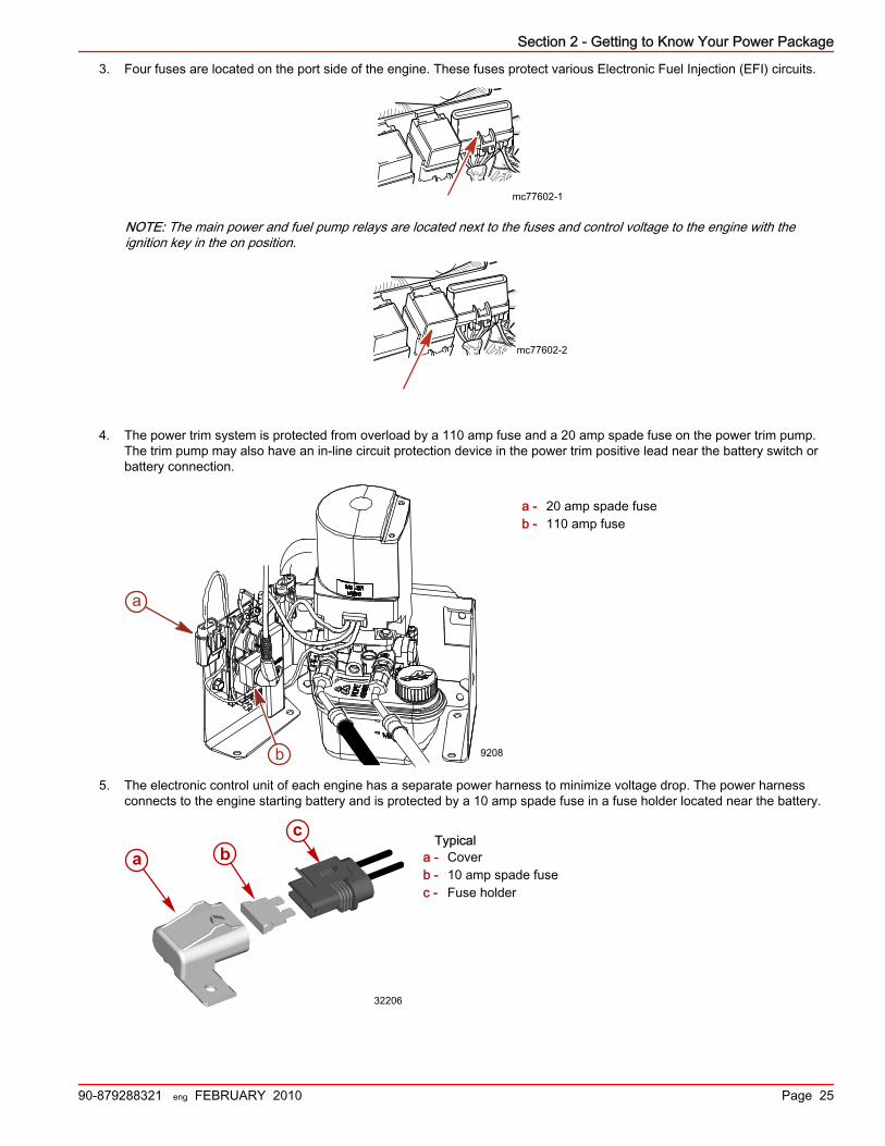
Section 2 - Getting to Know Your Power Package
90-879288321 eng FEBRUARY 2010 Page 25
3. Four fuses are located on the port side of the engine. These fuses protect various Electronic Fuel Injection (EFI) circuits.
mc77602-1
NOTE: The main power and fuel pump relays are located next to the fuses and control voltage to the engine with theignition key in the on position.
mc77602-2
4. The power trim system is protected from overload by a 110 amp fuse and a 20 amp spade fuse on the power trim pump.The trim pump may also have an in‑line circuit protection device in the power trim positive lead near the battery switch orbattery connection.
a - 20 amp spade fuseb - 110 amp fuse
5. The electronic control unit of each engine has a separate power harness to minimize voltage drop. The power harnessconnects to the engine starting battery and is protected by a 10 amp spade fuse in a fuse holder located near the battery.
Typicala - Coverb - 10 amp spade fusec - Fuse holder
a
b 9208
a bc
32206
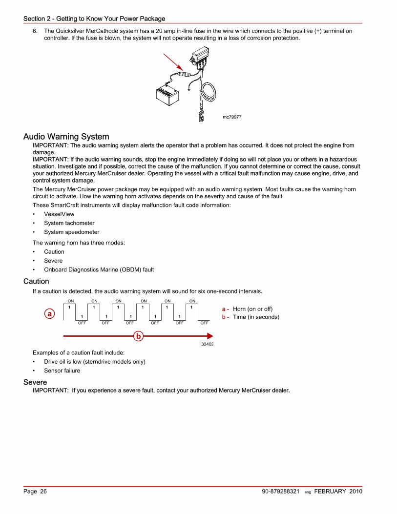
Section 2 - Getting to Know Your Power Package
Page 26 90-879288321 eng FEBRUARY 2010
6. The Quicksilver MerCathode system has a 20 amp in‑line fuse in the wire which connects to the positive (+) terminal oncontroller. If the fuse is blown, the system will not operate resulting in a loss of corrosion protection.
mc79977
Audio Warning SystemIMPORTANT: The audio warning system alerts the operator that a problem has occurred. It does not protect the engine fromdamage.IMPORTANT: If the audio warning sounds, stop the engine immediately if doing so will not place you or others in a hazardoussituation. Investigate and if possible, correct the cause of the malfunction. If you cannot determine or correct the cause, consultyour authorized Mercury MerCruiser dealer. Operating the vessel with a critical fault malfunction may cause engine, drive, andcontrol system damage.The Mercury MerCruiser power package may be equipped with an audio warning system. Most faults cause the warning horncircuit to activate. How the warning horn activates depends on the severity and cause of the fault.These SmartCraft instruments will display malfunction fault code information:• VesselView• System tachometer• System speedometer
The warning horn has three modes:• Caution• Severe• Onboard Diagnostics Marine (OBDM) fault
CautionIf a caution is detected, the audio warning system will sound for six one‑second intervals.
a - Horn (on or off)b - Time (in seconds)
Examples of a caution fault include:• Drive oil is low (sterndrive models only)• Sensor failure
SevereIMPORTANT: If you experience a severe fault, contact your authorized Mercury MerCruiser dealer.
ON ON
OFF
ON
OFF
ON
OFF
ON
OFF
ON
OFF
1
1
1
1
1
1
1
1
1
1
1
OFF
33402
a
b

Section 2 - Getting to Know Your Power Package
90-879288321 eng FEBRUARY 2010 Page 27
If a severe fault is detected, the audio warning system sounds for six seconds, turns off for six seconds, and sounds for sixmore seconds. Then the audio warning system sounds for two half‑second intervals every sixty seconds.
a - Horn (on or off)b - Time (in seconds)
Examples of a severe fault include:• Transmission fluid temperature is too hot (Inboard only)• Engine oil pressure is too low• Engine temperature is too hot• Seawater pressure is too low• Transmission pressure is low (Inboard only)
OBDM (On-Board Diagnostics Marine)If an OBDM fault is detected, the audio warning system sounds with one five‑second horn, then one short, ½‑second hornevery 60 seconds for certain faults related to the Emissions Control (EC) or the fuel system. Contact your authorized MercuryMerCruiser dealer for assistance.
a - Horn (on or off)b - Time (in seconds)
NOTE: Refer to the appropriate engine service manual for a detailed list and explanation of fault codes.
OBDM Malfunction Indicator Lamp (MIL)Boats powered by Emissions Control (EC) catalyzed engines may be equipped with a MIL (service engine light).• The engine will default to horn notification for OBDM faults if a MIL is not installed.
40388
a
b
ONON
6 6 6
OFFOFF
60 ½
ON
½
ON
OFF
60 ½
ON
½
ON
33404
a
OFF
ON
5 60 60 60½ ½ ½
ON ON ON
OFF OFF
b
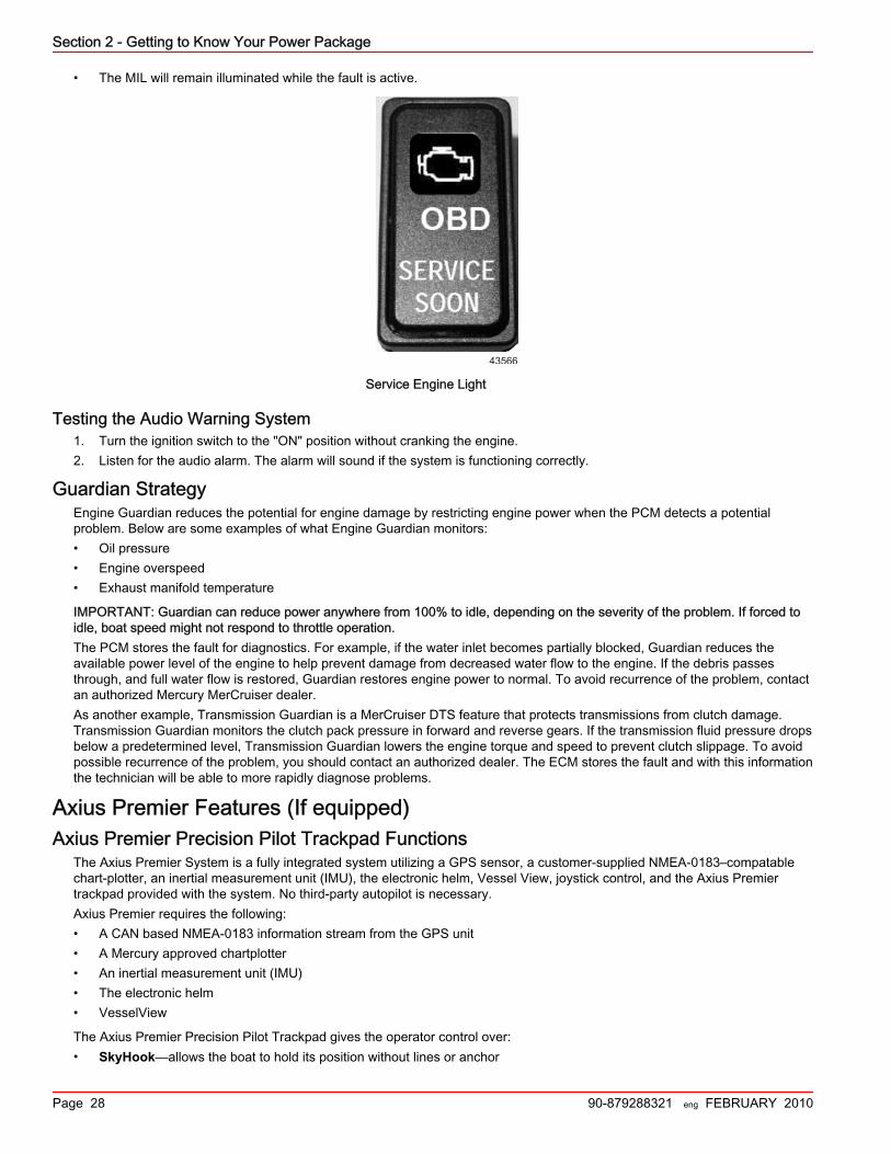
Section 2 - Getting to Know Your Power Package
Page 28 90-879288321 eng FEBRUARY 2010
• The MIL will remain illuminated while the fault is active.
43566
Service Engine Light
Testing the Audio Warning System1. Turn the ignition switch to the "ON" position without cranking the engine.2. Listen for the audio alarm. The alarm will sound if the system is functioning correctly.
Guardian StrategyEngine Guardian reduces the potential for engine damage by restricting engine power when the PCM detects a potentialproblem. Below are some examples of what Engine Guardian monitors:• Oil pressure• Engine overspeed• Exhaust manifold temperature
IMPORTANT: Guardian can reduce power anywhere from 100% to idle, depending on the severity of the problem. If forced toidle, boat speed might not respond to throttle operation.The PCM stores the fault for diagnostics. For example, if the water inlet becomes partially blocked, Guardian reduces theavailable power level of the engine to help prevent damage from decreased water flow to the engine. If the debris passesthrough, and full water flow is restored, Guardian restores engine power to normal. To avoid recurrence of the problem, contactan authorized Mercury MerCruiser dealer.As another example, Transmission Guardian is a MerCruiser DTS feature that protects transmissions from clutch damage.Transmission Guardian monitors the clutch pack pressure in forward and reverse gears. If the transmission fluid pressure dropsbelow a predetermined level, Transmission Guardian lowers the engine torque and speed to prevent clutch slippage. To avoidpossible recurrence of the problem, you should contact an authorized dealer. The ECM stores the fault and with this informationthe technician will be able to more rapidly diagnose problems.
Axius Premier Features (If equipped)Axius Premier Precision Pilot Trackpad Functions
The Axius Premier System is a fully integrated system utilizing a GPS sensor, a customer‑supplied NMEA‑0183–compatablechart‑plotter, an inertial measurement unit (IMU), the electronic helm, Vessel View, joystick control, and the Axius Premiertrackpad provided with the system. No third‑party autopilot is necessary.Axius Premier requires the following:• A CAN based NMEA‑0183 information stream from the GPS unit• A Mercury approved chartplotter• An inertial measurement unit (IMU)• The electronic helm• VesselView
The Axius Premier Precision Pilot Trackpad gives the operator control over:• SkyHook—allows the boat to hold its position without lines or anchor

Section 2 - Getting to Know Your Power Package
90-879288321 eng FEBRUARY 2010 Page 29
• Response—compensates for the effects of wind, waves, and currents on the boat's direction.• Auto Heading—controls the boat on a pre‑determined heading• Track Waypoint—controls the boat on a pre‑determined path with a single waypoint• Waypoint Sequence—controls the boat on a pre‑determined path with multiple waypoints
a - SkyHookb - Turn to starboardc - Waypoint Sequenced - Responsee - Track Waypointf - Auto Headingg - Resumeh - Turn to port
The buttons on the Precision Pilot Trackpad have the following functions:
Function Description
SkyHook Engages and disengages SkyHook. Mode is only available when the joystick is centered, both engines arerunning, GPS and Heading Sensors are available, and levers are in neutral.
Turn < and > Each press of the button causes a 10 degree course change in the Auto Heading mode. (A tap port orstarboard on the joystick initiates a one degree change in course.)
WaypointSequence
Engages Waypoint Sequence, driving the boat on a course set with multiple waypoints on the charplotter.Waypoint Sequence is available when the "WAYPOINT SEQUENCE" button is pressed, a NMEA‑0183stream is available from a chart plotter, and the GPS and heading sensor signals are available. When in"WAYPOINT SEQUENCE" mode, the joystick or "<" or ">" will cause the Precision Pilot to change toheading control and change the heading 1°.
ResponseIncreases or decreases the amount of control exerted by the Precision Pilot on disturbances to externalcourse changes in three levels. Selection will be in a "(123‑321)" format. The response levels can becalibrated.
TrackWaypoint
Engages Precision Pilot in (GPS) Track mode. Track can be engaged by either pressing the track button orpressing the auto button then the track button. Route Tracking is available when the "Track" button ispressed, a NMEA‑0183 stream is available from a chart plotter, and the GPS and heading sensor signalsare available. When in "Track" mode, the joystick or "<" or ">" will cause the Precision Pilot to change toheading control and change the heading 1°.
Auto Heading Engages Auto Heading mode. Heading control is available when the "Auto Heading" button is pressed, andGPS and IMU signals are available. (See "Turn < and >" for course adjustment information.)
Resume Resumes previous Auto/Track Course.
35301
b
a
cd
ef
g
h

Section 2 - Getting to Know Your Power Package
Page 30 90-879288321 eng FEBRUARY 2010
NOTE: Moving the steering wheel will always take control of the boat. A slight detent will have to be overcome to give theoperator feedback that the they are taking control from the Precision Pilot. The "Resume" button will return the Precision Pilot tocontrol in the previous mode.

Section 3 - On the Water
90-879288321 eng FEBRUARY 2010 Page 31
Section 3 - On the WaterTable of ContentsSafe Boating Suggestions.................................................... 32Carbon Monoxide Exposure................................................. 33
Be Alert To Carbon Monoxide Poisoning ..................... 33Stay Clear of Exhaust Areas ........................................ 33Good Ventilation .......................................................... 33Poor Ventilation ........................................................... 34
Basic Boat Operation............................................................ 34Trailering the Boat......................................................... 34Freezing Temperature Operation.................................. 34Drain Plug and Bilge Pump............................................34
Protecting People in the Water............................................. 34While You Are Cruising ................................................ 34While Boat Is Stationary ............................................... 35
High‑Speed and High‑Performance Operation..................... 35Passenger Safety in Pontoon Boats and Deck Boats.......... 35
Boats Having an Open Front Deck ............................... 35Boats With Front‑Mounted, Raised Pedestal FishingSeats ............................................................................ 35
Wave and Wake Jumping..................................................... 36Impact with Underwater Hazards......................................... 36
Drive Unit Impact Protection ......................................... 37Operating with Low Water Inlets in Shallow Water............... 37Conditions Affecting Operation............................................. 37
Weight Distribution (Passengers and Gear) Inside theBoat............................................................................... 37The Bottom of the Boat.................................................. 37Cavitation....................................................................... 38Ventilation...................................................................... 38Elevation and Climate.................................................... 38Propeller Selection.........................................................38
Getting Started..................................................................... 3820‑Hour Break‑In Period................................................ 38Launching and Boat Operation...................................... 39
Operation Chart ..................................................... 39Starting and Stopping the Engine.................................. 39
Starting the Engine ................................................ 39Stopping the Engine .............................................. 40
Throttle Only Operation................................................. 40Traditional Maneuvering with Steering and Thrust........ 41
To Maneuver the Boat in Forward ......................... 41
To Steer the Boat in Tight Turns at LowSpeeds .................................................................. 41To Spin the Boat at Low Speeds ........................... 41
Maneuvering with the Joystick....................................... 41Special Digital Throttle and Shift (DTS) Features.......... 45
Dock ...................................................................... 46Throttle Only .......................................................... 471 (Single) Lever ..................................................... 47Sync ...................................................................... 48
After Break‑In Period..................................................... 48End of First Season Checkup........................................ 48
Axius Premier (If equipped).................................................. 48Axius Premier Touchpad .............................................. 48
General Information ............................................... 48Heading Adjustment and Override ........................ 49Standby ................................................................. 49Standby and Active Lights ..................................... 49Power Icon ............................................................ 49Auto Heading ......................................................... 50Disengage Auto Heading ...................................... 53To Resume to a Heading ..................................... 53Changing VesselView Mode Display Times .......... 54
Skyhook......................................................................... 54Engaging (Activating) Skyhook ............................. 55The Skyhook Screen in VesselView ...................... 56Disengaging (Deactivating) Skyhook .................... 57
Response Button........................................................... 57Track Waypoint.............................................................. 58
Engaging Track Waypoint Mode ........................... 58Disengaging Track Waypoint Mode ...................... 59Turn Buttons or Joystick in Track WaypointMode ..................................................................... 59Auto Heading Button in Track Waypoint Mode .... 59Acknowledging a Turn During a WaypointArrival .................................................................... 59Waypoint Sequence .............................................. 61
Cruise Control................................................................ 63Contingent Operations.......................................................... 63
Port Engine–Only Operation.......................................... 63Axius Shift Override—Emergency Procedure................64
3

Section 3 - On the Water
Page 32 90-879288321 eng FEBRUARY 2010
Safe Boating SuggestionsTo safely enjoy the waterways, familiarize yourself with local and all other governmental boating regulations and restrictionsand consider the following suggestions.Know and obey all nautical rules and laws of the waterways.• We recommend that all powerboat operators complete a boating safety course. In the US, the U.S. Coast Guard Auxiliary,
the Power Squadron, the Red Cross, and your state or provincial boating law enforcement agency provide courses. Formore information in the US, call the Boat U.S. Foundation at 1‑800‑336‑BOAT (2628).
Perform safety checks and required maintenance.• Follow a regular schedule and ensure that all repairs are properly made.
Check safety equipment on board.• Here are some suggestions of the types of safety equipment to carry when boating:
• Approved fire extinguishers• Signal devices: flashlight, rockets or flares, flag and whistle or horn• Tools necessary for minor repairs• Anchor and extra anchor line• Manual bilge pump and extra drain plugs• Drinking water• Transistor radio• Paddle or oar• Spare propeller, thrust hubs, and an appropriate wrench• First aid kit and instructions• Water‑proof storage containers• Spare operating equipment, batteries, bulbs and fuses• Compass and map or chart of the area• Personal flotation device (1 per person on board)
Watch for signs of weather change and avoid foul weather and rough‑sea boating.Tell someone where you are going and when you expect to return.Passenger boarding.• Stop the engine whenever passengers are boarding, unloading or are near the back (stern) of the boat. Shifting the drive
unit into neutral is not sufficient.
Use personal flotation devices.• Federal Law requires that there be a U. S. Coast Guard approved life jacket (personal flotation device), correctly sized and
readily accessible for every person on board, plus a throwable cushion or ring. We strongly advise that everyone wear alife jacket at all times while in the boat.
Prepare other boat operators.• Instruct at least 1 person on board in the basics of starting and operating the engine and boat handling in case the driver
becomes disabled or falls overboard.
Do not overload your boat.• Most boats are rated and certified for maximum load (weight) capacities (refer to your boat capacity plate). Know your
boat's operating and loading limitations. Know if your boat will float if full of water. When in doubt, contact your authorizedMercury MerCruiser dealer or the boat manufacturer.
Ensure that everyone in the boat is properly seated.• Do not allow anyone to sit or ride on any part of the boat that was not intended for such use. This includes the backs of
seats, gunwales, transom, bow, decks, raised fishing seats and any rotating fishing seat; anywhere that suddenunexpected acceleration, sudden stopping, unexpected loss of boat control or sudden boat movement could cause aperson to be thrown overboard or into the boat. Ensure that all passengers have a proper seat and are in it before any boatmovement.
Never be under the influence of alcohol or drugs while boating (it is the law).• They impair your judgment and greatly reduce your ability to react quickly.
Know your boating area and avoid hazardous locations.Be alert.

Section 3 - On the Water
90-879288321 eng FEBRUARY 2010 Page 33
• The operator of the boat is responsible by law to maintain a proper lookout by sight and hearing. The operator must havean unobstructed view particularly to the front. No passengers, load or fishing seats should block the operators view whenthe boat is above idle or planing transition speed. Watch out for others, the water and your wake.
Never drive your boat directly behind a water skier in case the skier falls.• As an example, your boat traveling at 40 km/h (25 MPH) will overtake a fallen skier who was 61 m (200 ft.) in
front of you in 5 seconds.
Watch fallen skiers.• When using your boat for water skiing or similar activities, always keep a fallen or down skier on the operator's side of the
boat while returning to attend to the skier. The operator should always have the down skier in sight and never back up tothe skier or anyone in the water.
Report accidents.• Boat operators are required by law to file a Boating Accident Report with their state boating law enforcement agency when
their boat is involved in certain boating accidents. A boating accident must be reported if 1) there is loss of life or probableloss of life, 2) there is personal injury requiring medical treatment beyond first aid, 3) there is damage to boats or otherproperty where the damage value exceeds $500.00 or 4) there is complete loss of the boat. Seek further assistance fromlocal law enforcement.
Carbon Monoxide ExposureBe Alert To Carbon Monoxide Poisoning
Carbon monoxide (CO) is a deadly gas that is present in the exhaust fumes of all internal combustion engines, including theengines that propel boats, and the generators that power boat accessories. By itself, CO is odorless, colorless, and tasteless,but if you can smell or taste engine exhaust, you are inhaling CO.Early symptoms of carbon monoxide poisoning, which are similar to the symptoms of seasickness and intoxication, includeheadache, dizziness, drowsiness, and nausea.
! WARNINGInhaling engine exhaust gases can result in carbon monoxide poisoning, which can lead to unconsciousness, brain damage,or death. Avoid exposure to carbon monoxide.Stay clear from exhaust areas when engine is running. Keep the boat well‑ventilated while at rest or underway.
Stay Clear of Exhaust Areas
41127
Engine exhaust gases contain harmful carbon monoxide. Avoid areas of concentrated engine exhaust gases. When enginesare running, keep swimmers away from the boat, and do not sit, lie, or stand on swim platforms or boarding ladders. Whileunderway, do not allow passengers to be positioned immediately behind the boat (platform dragging, teak/body surfing). Thisdangerous practice not only places a person in an area of high engine exhaust concentration, but also subjects them to thepossibility of injury from the boat propeller.
Good VentilationVentilate the passenger area, open side curtains or forward hatches to remove fumes.Example of desired air flow through the boat:
43367

Section 3 - On the Water
Page 34 90-879288321 eng FEBRUARY 2010
Poor VentilationUnder certain running or wind conditions, permanently enclosed or canvas enclosed cabins or cockpits with insufficientventilation may draw in carbon monoxide. Install one or more carbon monoxide detectors in your boat.Although the occurrence is rare, on a very calm day, swimmers and passengers in an open area of a stationary boat thatcontains or is near a running engine may be exposed to a hazardous level of carbon monoxide.1. Examples of poor ventilation while the boat is stationary:
a - Operating the engine when the boatis moored in a confined space
b - Mooring close to another boat thathas its engine operating
2. Examples of poor ventilation while the boat is moving:
a - Operating the boat with thetrim angle of the bow toohigh
b - Operating the boat with noforward hatches open(station wagon effect)
Basic Boat OperationTrailering the Boat
Your boat can be trailered with the sterndrive unit in the up or down position. Adequate clearance is required between the roadand sterndrive when transporting.If adequate road clearance is a problem, place the sterndrive unit in full trailer position and support it with an optional trailer kitwhich is available from your authorized Mercury MerCruiser dealer.
Freezing Temperature OperationIMPORTANT: If the boat is operated during periods of freezing temperature, precautions must be taken to prevent freezedamage to the power package. Damage caused by freezing is not covered by Mercury MerCruiser Limited Warranty.
Drain Plug and Bilge PumpThe engine compartment in your boat is a natural place for water to collect. For this reason, boats are normally equipped with adrain plug and/or a bilge pump. It is very important to check these items on a regular basis to ensure that the water level doesnot come into contact with your power package. Components on your engine will be damaged if submerged. Damage causedby submersion is not covered by the Mercury MerCruiser Limited Warranty.
Protecting People in the WaterWhile You Are Cruising
It is very difficult for a person in the water to take quick action to avoid a boat heading in their direction, even at slow speeds.
21604
Always slow down and exercise extreme caution any time you are boating in an area where there might be people in the water.Whenever a boat is moving (even coasting) and the gear shift is in neutral, there is sufficient force by the water on the propellerto cause the propeller to rotate. This neutral propeller rotation can cause serious injury.
21626
ab
ab
43368

Section 3 - On the Water
90-879288321 eng FEBRUARY 2010 Page 35
While Boat Is Stationary
! WARNINGA spinning propeller, a moving boat, or any solid device attached to the boat can cause serious injury or death to swimmers.Stop the engine immediately whenever anyone in the water is near your boat.
Shift into neutral and shut off the engine before allowing people to swim or be in the water near your boat.
High‑Speed and High‑Performance OperationIf your boat is considered a high‑speed or high‑performance boat with which you are unfamiliar, we recommend that you neveroperate it at its high speed capability without first requesting an initial orientation and demonstration ride with your dealer or anoperator experienced with your boat. For additional information, refer to Hi‑Performance Boat Operation booklet(90‑849250‑R2) from your dealer, distributor or Mercury Marine.
Passenger Safety in Pontoon Boats and Deck BoatsWhenever the boat is in motion, observe the location of all passengers. Do not allow any passengers to stand or use seatsother than those designated for traveling faster than idle speed. A sudden reduction in boat speed, such as plunging into alarge wave or wake, a sudden throttle reduction, or a sharp change of boat direction, could throw them over the front of boat.Falling over the front of the boat between the two pontoons will position them to be run over.
Boats Having an Open Front DeckNo one should ever be on the deck in front of the fence while the boat is in motion. Keep all passengers behind the front fenceor enclosure.Persons on the front deck could easily be thrown overboard or persons dangling their feet over the front edge could get theirlegs caught by a wave and pulled into the water.
mc79555-1
! WARNINGSitting or standing in an area of the boat not designed for passengers at speeds above idle can cause serious injury or death.Stay back from the front end of deck boats or raised platforms and remain seated while the boat is in motion.
Boats With Front‑Mounted, Raised Pedestal Fishing SeatsElevated fishing seats are not intended for use when the boat is traveling faster than idle or trolling speed. Sit only in seatsdesignated for traveling at faster speeds.Any unexpected, sudden reduction in boat speed could result in the elevated passenger falling over the front of the boat.
mc79557-1

Section 3 - On the Water
Page 36 90-879288321 eng FEBRUARY 2010
Wave and Wake Jumping! WARNING
Wave or wake jumping can cause serious injury or death from occupants being thrown within or out of the boat. Avoid waveor wake jumping whenever possible.
mc79680-1
Operating recreational boats over waves and wakes is a natural part of boating. However, when this activity is done withenough speed to force the boat hull partially or completely out of the water, certain hazards arise, particularly when the boatre‑enters the water.The primary concern is the boat changing direction while in the midst of the jump. In such cases the landing may cause theboat to violently veer in a new direction. Such a sharp change in direction or turn can cause occupants to be thrown out of theirseats or out of the boat.There is another less common hazardous result from allowing your boat to launch off of a wave or wake. If the bow of your boatpitches down far enough while airborne, upon water contact it may penetrate under the water surface and submarine for aninstant. This will bring the boat nearly to a stop in an instant and can send the occupants flying forward. The boat may also veersharply to one side.
Impact with Underwater HazardsReduce speed and proceed with caution whenever you're driving a boat in shallow water or in areas where the waters aresuspected of having underwater obstacles that could be struck by the underwater drive components, rudder or the boat bottom.
mc79679-1
IMPORTANT: The most important thing you can do to help reduce injury or impact damage from striking a floating orunderwater object is control the boat speed. Under these conditions, boat speed should be kept to a maximum speed of24 to 40 km/h (15 to 25 mph).Striking a floating/underwater object may result in an infinite number of situations. Some of these situations could result in thefollowing:• The boat could move suddenly in a new direction. Such a sharp change in direction or turn can cause occupants to be
thrown out of their seats or out of the boat.• A rapid reduction in speed. This will cause occupants to be thrown forward, even out of the boat.• Impact damage to the underwater drive components, rudder and/or boat.
Keep in mind, one of the most important things you can do to help reduce injury or impact damage in these situations is controlthe boat speed. Boat speed should be kept to a minimum planing speed when driving in waters known to have underwaterobstacles.After striking a submerged object, stop the engine as soon as possible and inspect the drive system for any broken or looseparts. If damage is present or suspected, the power package should be taken to an authorized Mercury MerCruiser dealer for athorough inspection and necessary repair.The boat should be checked for hull fractures, transom fractures and water leaks.Operating with damaged underwater drive components, rudder or boat bottom could cause additional damage to other parts ofthe power package, or could affect control of the boat. If continued operation is necessary, do so at greatly reduced speeds.

Section 3 - On the Water
90-879288321 eng FEBRUARY 2010 Page 37
! WARNINGOperating a boat or engine with impact damage can result in product damage, serious injury, or death. If the vesselexperiences any form of impact, have an authorized Mercury Marine dealer inspect and repair the vessel or power package.
Drive Unit Impact ProtectionThe power trim hydraulic system is designed to provide impact protection for the sterndrive unit. If a submerged object is struckwhile the boat is moving forward, the hydraulic system will cushion the kickup of the sterndrive unit as it clears the object,reducing damage to the unit. After the sterndrive unit has cleared the object, the hydraulic system allows the sterndrive unit toreturn to its original operating position, preventing loss of steering control and engine overspeed.Use extreme caution when operating in shallow water or where underwater objects are known to be present. No impactprotection is provided in reverse; use extreme care to prevent striking submerged objects while operating in reverse.IMPORTANT: Impact protection system cannot be designed to ensure total protection from impact damage under allconditions.
Operating with Low Water Inlets in Shallow Water
a - Low Water Inlets
NOTICEOperating in shallow water can cause severe engine damage due to clogged water inlets. Ensure that the water inlets on thegearcase do not ingest sand, silt, or other debris, which can restrict or stop cooling water supply to the engine.
Extreme care should be exercised when operating a boat equipped with low water inlets while maneuvering in shallow water.Also, avoid beaching a boat with the engine operating.
Conditions Affecting OperationWeight Distribution (Passengers and Gear) Inside the Boat
Shifting weight to rear (stern):• Generally increases speed and engine RPM• Causes bow to bounce in choppy water• Increases danger of following wave splashing into the boat when coming off plane• At extremes, can cause the boat to porpoise
Shifting weight to front (bow):• Improves ease of planing• Improves rough water ride• At extremes, can cause the boat to veer back and forth (bow steer)
The Bottom of the BoatTo maintain maximum speed, the boat bottom should be:• Clean, free of barnacles and marine growth• Free of distortion; nearly flat where it contacts the water• Straight and smooth, fore and aft
Marine vegetation may accumulate when the boat is docked. This growth must be removed before operation; it may clog thewater inlets and cause the engine to overheat.
mc75827-1a

Section 3 - On the Water
Page 38 90-879288321 eng FEBRUARY 2010
CavitationCavitation occurs when water flow cannot follow the contour of a fast‑moving underwater object, such as a gear housing or apropeller. Cavitation increases propeller speed while reducing boat speed. Cavitation can seriously erode the surface of thegear housing or the propeller. Common causes of cavitation are:• Weeds or other debris snagged on the propeller• Bent propeller blade• Raised burrs or sharp edges on the propeller
VentilationVentilation is caused by surface air or exhaust gases that are introduced around the propeller resulting in propeller speed‑upand a reduction in boat speed. Air bubbles strike the propeller blade and cause erosion of the blade surface. If allowed tocontinue, eventual blade failure (breakage) will occur. Excessive ventilation is usually caused by:• Drive unit trimmed out too far• A missing propeller diffuser ring• A damaged propeller or gear housing, which allows exhaust gases to escape between propeller and gear housing• Drive unit installed too high on transom
Elevation and ClimateElevation and climate changes will affect the performance of your power package. Loss of performance can be caused by:• Higher elevations• Higher temperatures• Low barometric pressures• High humidity
For you to have optimum engine performance under changing weather conditions, it is essential that the engine be propped toallow the engine to operate at or near the top end of the specified maximum RPM range with a normal boat load during yournormal boating weather conditions.In most cases, recommended RPM can be achieved by changing to a lower pitch propeller.
Propeller SelectionIMPORTANT: The engines covered in this manual are equipped with an RPM rev‑limiter that is set to an upper RPM limit. Thislimit, which is slightly above the normal operating range of the engine, helps prevent damage from excessive engine RPM.Once the RPM returns to the recommended operating RPM range, normal engine operation resumes.The boat manufacturer and the selling dealer are responsible for equipping the power package with the correct propeller. Referto Mercury Marine's web page http://www.mercurymarine.com/everything_you_need_to_know_about_propellers6.Select a propeller that will allow the engine power package to operate at or near the top end of the recommended WOToperating RPM range with a normal load.If full‑throttle operation is below the recommended range, the propeller must be changed to prevent loss of performance andpossible engine damage. On the other hand, operating an engine above the recommended operating RPM range will causehigher than normal wear and damage.After initial propeller selection, the following common problems may require that the propeller be changed to a lower pitch.• Warmer weather and greater humidity cause a loss of RPM.• Operating in a higher elevation causes a loss of RPM.• Operating with a dirty boat bottom causes a loss of RPM.• Operating with increased load (additional passengers, pulling skiers) causes a loss of RPM.
For better acceleration, such as is needed for waterskiing, use the next lower pitch propeller. When not pulling skiers, do notoperate at full throttle when using the lower pitch propeller.
Getting Started20‑Hour Break‑In Period
IMPORTANT: The first 20 hours of operation is the engine break‑in period. Correct break‑in is essential to obtain minimum oilconsumption and maximum engine performance. During this break‑in period, the following rules must be observed:• Do not operate below 1500 RPM for extended periods of time for the first 10 hours. Shift into gear as soon as possible after
starting and advance the throttle above 1500 rpm if conditions permit safe operation.• Do not operate at one speed consistently for extended periods.

Section 3 - On the Water
90-879288321 eng FEBRUARY 2010 Page 39
• Do not exceed 3/4 throttle during the first 10 hours. During the next 10 hours, occasional operation at full throttle ispermissible (5 minutes at a time maximum).
• Avoid full throttle acceleration from idle speed.• Do not operate at full throttle until the engine reaches normal operating temperature.• Frequently check engine oil level. Add oil as needed. It is normal for oil consumption to be high during the break‑in period.
Launching and Boat OperationIMPORTANT: Install bilge drain plug prior to launching boat.
Operation Chart
Operation Chart
BEFORE STARTING AFTER STARTING WHILE UNDERWAY AFTER STOPPING
Install bilge drain plug.Observe all gauges tocheck condition of engine.If not normal, stop engine.
Observe all gauges tocheck condition ofengine. If not normal,stop engine.
Turn ignition key to the"OFF" position.
Open engine hatch. Check for fuel, oil, water,fluid and exhaust leaks.
Listen for the audioalarm.
Turn battery switch to the"OFF" position.
Turn battery switch on. Check shift and throttlecontrol operation. Close fuel shut off valve.
Operate bilge blowers. Check steering operation. Close seacock, ifequipped.
Open fuel shut off valve. Flush cooling system if insaltwater.
Open seacock, if equipped. Drain bilge.
Close the drain system.
Place sterndrive unit in full down/inposition.
Check the engine oil.
Perform all other checks specified by yourdealer and/or boat builder.
Listen for Audio Warning Alarm to soundwhen the ignition switch is in the "ON"position.
Starting and Stopping the EngineNOTE: Perform only those functions applicable to your power package.
Starting the Engine1. Check all items listed in the Operation Chart.2. Place the remote control handle in neutral.
NOTICEWithout sufficient cooling water, the engine, the water pump, and other components will overheat and suffer damage. Providea sufficient supply of water to the water inlets during operation.
! WARNINGExplosive fumes contained in the engine compartment can cause serious injury or death from fire or explosion. Beforestarting the engine, operate the bilge blower or vent the engine compartment for at least five minutes.

Section 3 - On the Water
Page 40 90-879288321 eng FEBRUARY 2010
NOTE: MerCruiser DTS models are equipped with SmartStart. The SmartStart feature incorporates push‑button starting.Rather than holding the start button or key switch to start the engine and then releasing it when the engine starts,SmartStart completely controls the starting process. When the start button is pushed, the DTS system signals the enginePCM to start the engine. If the engine does not start, the starting process times out after a few seconds or when the enginereaches 400 RPM. Attempting to start the engine with the engine already running will turn the engine off.
3. Turn the ignition key to the "RUN" position.
! WARNINGA spinning propeller, a moving boat, or any solid device attached to the boat can cause serious injury or death to swimmers.Stop the engine immediately whenever anyone in the water is near your boat.
4. Turn the ignition key switch to the "START" position then release, or depress the start/stop button and release. If theengine is cold, allow the engine to operate at idle for 6–10 minutes or until the engine temperature reaches 60° C (140° F).
5. If the engine does not start after three attempts:a. Push the throttle‑only button and position the remote control handle or throttle lever to the 1/4 throttle position.b. Turn the ignition key to "start." Release key when the engine starts and allow the switch to return to the "on" position.
6. If the engine does not start after step 5:a. Move the remote control lever to the full throttle position, then return to 1/4 throttle.b. Turn the ignition key to "START." Release key when the engine starts and allow the switch to return to the "on"
position.7. Inspect the power package for fuel, oil, water, and exhaust leaks.8. Move the control handle with a firm, quick motion forward to shift to forward gear, or backward to shift to reverse. After
shifting, advance throttle to desired setting.
NOTICEShifting into gear at engine speeds above idle will damage the drive system. Shift the drive into gear only when the engine isoperating at idle.
Stopping the Engine1. Move the remote control handle to neutral/idle and allow the engine to slow to idle speed. If the engine has been operated
at high speed for a long period of time, allow the engine to cool at idle speed for 3 to 5 minutes.2. The engine can be stopped by any one of the following four methods:
a. Move the ignition key switch to the "ACCESSORY" or "OFF" position. The engine will stop and the control system willbe deactivated.
b. Depress the start/stop button, if equipped. The engine will stop and the control system will remain active.c. Momentarily move the ignition key switch to the "START" position, then release immediately. The control system will
recognize that the engine is running and will stop the engine. The control system will remain active. Moving theignition key switch to the "START" position again will issue a start request to the control system and the controlsystem will start the engine, if appropriate.
d. Activate the lanyard stop switch, if equipped. The engine will stop, but the control system will remain active. Thecontrol system will not allow the engine to start if the lanyard stop switch is activated.
Throttle Only OperationNOTE: When operating in throttle only (neutral) mode, the DTS Control System will not allow the engine speed to increaseabove 3500 RPM.Console mount remote controls are equipped with a throttle‑only button. To activate throttle only mode:1. Refer to the Remote Controls section for remote control features.2. Move the control lever to the idle/neutral position.3. Depress the throttle‑only button, and move the control lever to the idle/forward or idle/reverse position. The DTS control
system will sound two beeps on the audio warning horn to indicate throttle only mode is active. On console mount remotecontrols, the neutral light will begin to blink.
4. Advancing the control lever beyond the idle/forward or idle/reverse position will cause engine speed to increase.IMPORTANT: Moving the control lever back to the idle/neutral position will not deactivate the throttle only mode or allowthe engine to shift into gear.
5. Throttle only mode is deactivated by moving the control lever to the idle/neutral position and pressing the throttle onlybutton. Moving the control lever from the idle/neutral position to the idle/forward or idle/reverse position without pressingthe throttle‑only button will just increase the engine speed. Be sure to take both engines out of throttle only before use.

Section 3 - On the Water
90-879288321 eng FEBRUARY 2010 Page 41
Traditional Maneuvering with Steering and ThrustYou can maneuver your Axius‑equipped vessel much like a traditional sterndrive boat. However, the Axius drive systemexpands the maneuvering capability of your vessel at both slow and planing speeds. At slow speeds, the drive system iscapable of directing the thrust to produce more responsive turning of the vessel. The Axius drive system featurescounter‑rotating propellers that do not produce any sideways motion when accelerating or slowing down.NOTE: During slow‑speed turning with the wheel, the drive on the inside turns as much as 42° to create very tight turns. Unliketraditional boats, you can increase power to the inside drive to tighten the turn.
To Maneuver the Boat in ForwardPlace one or both engines in forward gear and steer with the steering wheel as you would any comparable boat.
To Steer the Boat in Tight Turns at Low Speeds• To turn the boat in tight turns at low speeds, turn the wheel in the direction of the turn.• To increase the turn rate of the boat after the wheel is completely turned, you may increase the power to the inside drive.
To Spin the Boat at Low Speeds• To spin to the right, place the starboard engine in reverse and the port engine in forward.• To spin to the left, place the port engine in reverse and the starboard engine in forward.• To increase the rate of turn, simultaneously adjust each ERC lever for more throttle.
Maneuvering with the Joystick
! WARNINGA spinning propeller, a moving boat, or any solid device attached to the boat can cause serious injury or death to swimmers.Stop the engine immediately whenever anyone in the water is near your boat.
The joystick provides an intuitive driver interface to maneuver the vessel. Operating the vessel with the joystick is well suited forclose quarter operations and when docking. The computer control system automatically calculates the steering angle of eachdrive, the throttle level, and the proper gear to push or rotate the boat in a direction corresponding to a joystick movement ortwist. For example, if you move the joystick sideways, the computer control system applies a thrust to the boat in the sidewaysdirection. Rotating the joystick prompts the computer to create forces that rotate the boat around its center. You can move androtate the joystick at the same time, allowing intricate movements in tight quarters.The joystick is proportional, which means that the greater distance from the center that the joystick is moved, the more thrustthat is applied to the boat in that direction, to move the boat.The computer control system automatically attempts to dampen bow swinging during joystick operation. If the joystick is nottwisted, the computer measures the yaw rate of the boat and actively counteracts the yaw motion of the boat.For joystick movement of the boat:1. Both engines must be running for the Joystick to operate.2. For best control, trim both drives to the full down position.3. Move both electronic remote control (ERC) levers to the neutral position.4. Move the joystick in the direction that you want the boat to move, or twist the joystick in the direction that you want the boat
to rotate. The joystick can be moved and rotated at the same time.The following table gives some limited examples of the basic responses to inputs from the joystick.

Section 3 - On the Water
Page 42 90-879288321 eng FEBRUARY 2010
Maneuvering with the Joystick
Joystick Input Boat Response Movement(shown from light gray to dark gray)
24705
Boat moves forward
25928
24706
Boat moves aft
25927
24707
Boat moves to starboard without rotating
25929
24708
Boat moves to port without rotating
25931

Section 3 - On the Water
90-879288321 eng FEBRUARY 2010 Page 43
Joystick Input Boat Response Movement(shown from light gray to dark gray)
24709
Boat moves diagonally forward and to thestarboard without rotating
25926
24710
Boat moves diagonally aft and to thestarboard without rotating
25924
24711
Boat moves diagonally aft and to the portwithout rotating
25923
24712
Boat moves diagonally forward and to the portwithout rotating
25925
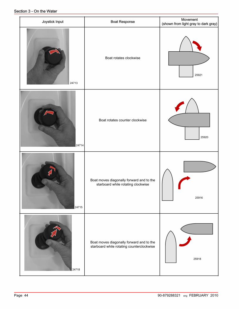
Section 3 - On the Water
Page 44 90-879288321 eng FEBRUARY 2010
Joystick Input Boat Response Movement(shown from light gray to dark gray)
24713
Boat rotates clockwise
25921
24714
Boat rotates counter clockwise
25920
24715
Boat moves diagonally forward and to thestarboard while rotating clockwise
25916
24718
Boat moves diagonally forward and to thestarboard while rotating counterclockwise
25918

Section 3 - On the Water
90-879288321 eng FEBRUARY 2010 Page 45
Joystick Input Boat Response Movement(shown from light gray to dark gray)
24719
Boat moves diagonally forward and to the portwhile rotating counterclockwise
25917
24720
Boat moves to the port while rotatingclockwise
25930
Special Digital Throttle and Shift (DTS) FeaturesThe DTS system features several alternate operational modes for the Electronic Remote Control (ERC) levers. Any of the listedfeatures can operate simultaneously and can help you with:• Warming the engines.• Synchronizing the engines.• Accessing the slow‑speed trolling features of the integrated transmission system.
28090
c
de
f
g
b
a
h
Yacht handled ERC levers with DTS trackpad, Typical
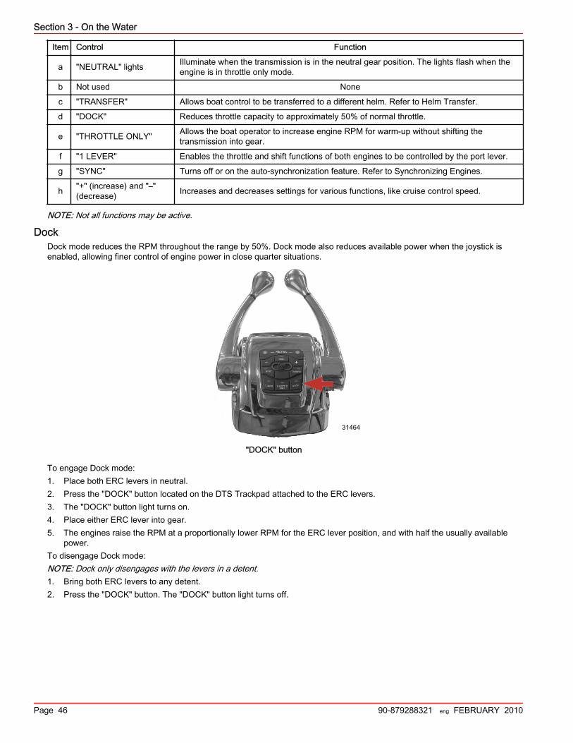
Section 3 - On the Water
Page 46 90-879288321 eng FEBRUARY 2010
Item Control Function
a "NEUTRAL" lights Illuminate when the transmission is in the neutral gear position. The lights flash when theengine is in throttle only mode.
b Not used None
c "TRANSFER" Allows boat control to be transferred to a different helm. Refer to Helm Transfer.
d "DOCK" Reduces throttle capacity to approximately 50% of normal throttle.
e "THROTTLE ONLY" Allows the boat operator to increase engine RPM for warm‑up without shifting thetransmission into gear.
f "1 LEVER" Enables the throttle and shift functions of both engines to be controlled by the port lever.
g "SYNC" Turns off or on the auto‑synchronization feature. Refer to Synchronizing Engines.
h "+" (increase) and "–"(decrease) Increases and decreases settings for various functions, like cruise control speed.
NOTE: Not all functions may be active.
DockDock mode reduces the RPM throughout the range by 50%. Dock mode also reduces available power when the joystick isenabled, allowing finer control of engine power in close quarter situations.
31464
"DOCK" button
To engage Dock mode:1. Place both ERC levers in neutral.2. Press the "DOCK" button located on the DTS Trackpad attached to the ERC levers.3. The "DOCK" button light turns on.4. Place either ERC lever into gear.5. The engines raise the RPM at a proportionally lower RPM for the ERC lever position, and with half the usually available
power.To disengage Dock mode:NOTE: Dock only disengages with the levers in a detent.1. Bring both ERC levers to any detent.2. Press the "DOCK" button. The "DOCK" button light turns off.

Section 3 - On the Water
90-879288321 eng FEBRUARY 2010 Page 47
Throttle Only
31465
"THROTTLE ONLY" button
To engage Throttle Only mode:1. Place both ERC levers in neutral.2. Press the "THROTTLE ONLY" button, located on the DTS trackpad.3. The "THROTTLE ONLY" button light illuminates and the neutral lights blink.4. Place either ERC lever into gear.5. The RPM of the engines can be increased, while the transmissions remains in Neutral.NOTE: Pressing the "THROTTLE ONLY" button while the ERC levers are in gear, turns off the button light, but the boatremains in throttle only mode until you place the levers in neutral.To disengage throttle only mode:1. Bring both ERC levers to neutral. Throttle only will not disengage unless the ERC levers are in neutral.2. Press the "THROTTLE ONLY" button. The "THROTTLE ONLY" button light turns off.3. The neutral lights remains on.
1 (Single) LeverThe Axius system features the ability to command both engines with a single lever. This feature simplifies engine managementduring rough sea conditions by allowing you to grasp a single lever to command both engines simultaneously.
31466
"1 LEVER" button
To engage 1 (single) lever mode:1. Place both ERC levers in neutral.2. Press the "1 LEVER" button located on the DTS Trackpad attached to the ERC levers.

Section 3 - On the Water
Page 48 90-879288321 eng FEBRUARY 2010
3. The "1 LEVER" button lights.4. Place the starboard ERC lever into gear.5. The engine RPM raises and lowers simultaneously while the transmissions remain in the same gear.To disengage 1 (single) lever mode:1. Place both ERC levers in neutral.2. Press the "1 LEVER" button. The "1 LEVER" button light turns off.
SyncThe Axius system features Sync, an automatic engine synchronization feature, which engages automatically at key‑up. Syncmonitors the position of both levers. If both levers are within 10% of one another, the port engine synchronizes to the starboardengine's RPM. The smartcraft system will automatically disengage Sync at the last 10% of lever range to allow each engine theability to reach maximum available RPM. Sync cannot engage until its minimum RPM is met.VesselView shows an orange icon if the engines exceed a 10% difference in RPM of each other, and the icon turns red whenthey synchronize. The icon turns off when Sync is off.
31467
"SYNC" button
To disengage Sync mode:1. Place the ERC levers in any detent.2. Press the "SYNC" button.To re‑engage Sync mode, press the "SYNC" button.
After Break‑In PeriodTo help extend the life of your Mercury MerCruiser power package:• Ensure the propeller allows the engine to operate at or near the top of the specified WOT RPM range (Refer to
Specifications and Maintenance) when at full throttle with a normal boat load.• Operate at 3/4 throttle setting or lower. Refrain from prolonged operation at WOT RPM.• Change the engine oil and oil filter. Refer to Maintenance.
End of First Season CheckupAt the end of the first season of operation, contact an authorized Mercury MerCruiser dealer to discuss and/or performscheduled maintenance items. If you are in an area where the product is operated continuously, year‑round, you should contactyour dealer at the end of the first 100 hours of operation or once yearly, whichever occurs first.
Axius Premier (If equipped)Axius Premier TouchpadGeneral Information
NOTE: Not all of the functions of the Axius system work when DTS functions are engaged. Disengage the DTS functions to usethe functions of Axius track pad.• Axius Premier functions are controlled through the Axius touchpad only.

Section 3 - On the Water
90-879288321 eng FEBRUARY 2010 Page 49
• Axius Premier touchpad screens appear on the VesselView for three seconds.• Pressing any button on VesselView dismisses the Axius Premier CAN touchpad screen from the VesselView screen,
unless the screen was chosen from the VesselView environment menu.
The following information shows the location and explains the function of the Axius touchpad lights and buttons.
Heading Adjustment and OverrideWhen Auto Heading is engaged, the steering wheel feels locked into a detent. Approximately 3.4–4.5 kg (8–10 lb.) of force arerequired to overcome this detent. Manually overcoming the steering wheel's detent puts Axius into standby mode.1. When Auto Heading is engaged the "TURN" buttons provide a 10° course correction for each press to the port or
starboard.2. The joystick provides a 1° course correction for each press to the port or starboard.
Standby• In standby mode, the display shows a digital compass value and the angle of the drives.• The compass value is the current heading from the Axius CAN.• The icon labeled "OFF" indicates the Axius track pad is not engaged.
Standby and Active LightsAxius Premier trackpad is off when the "STANDBY" light is illuminated. You must press a button to activate AxiusThe "ACTIVE" light is illuminated when one mode of Axius is on.
a - "STANDBY" lightb - "ACTIVE" light
Power Icon
The power icon indicates a button that engages or disengages an Axius Premier touchad function indicated on the button.Only one function can be on at a time.
If you press a button that has the power icon when that button light is on, the light turns off for that button and the"STANDBY" light illuminates.
35564
a b

Section 3 - On the Water
Page 50 90-879288321 eng FEBRUARY 2010
If you press a button with the power icon when that button light is off, the light turns on for that button, a single beep sounds,and the "ACTIVE" light illuminates.
Buttons with power iconsa - "SKYHOOK" buttonb - "AUTO HEADING" buttonc - "TRACK WAYPOINT" button
Auto Heading1. At least one engine must be running for auto heading to function.2. Press the "AUTO HEADING" button to engage Axius. The button illuminates and beeps once. The button will beep twice if
auto heading does not engage.
a - Indicator lampb - "AUTO HEADING" button
35563
a
b c
35561
ab
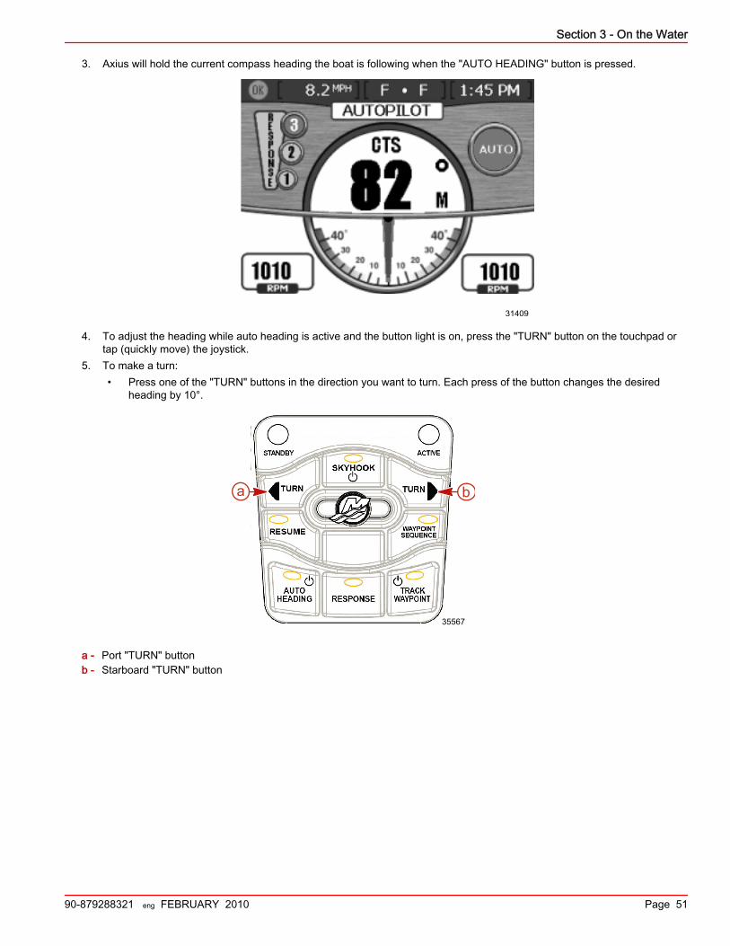
Section 3 - On the Water
90-879288321 eng FEBRUARY 2010 Page 51
3. Axius will hold the current compass heading the boat is following when the "AUTO HEADING" button is pressed.
31409
4. To adjust the heading while auto heading is active and the button light is on, press the "TURN" button on the touchpad ortap (quickly move) the joystick.
5. To make a turn:• Press one of the "TURN" buttons in the direction you want to turn. Each press of the button changes the desired
heading by 10°.
a - Port "TURN" buttonb - Starboard "TURN" button
35567
a b

Section 3 - On the Water
Page 52 90-879288321 eng FEBRUARY 2010
• Tap the joystick in the direction you want to turn. Tap the joystick left (port) or right (starboard) to adjust your courseby 1°.
24707
Adjusting the heading to starboard (port opposite)
6. To disengage auto heading, turn the steering wheel or press the "AUTO HEADING" button. A single beep sounds when itdisengages. If the steering wheel is used to disengage auto heading, the "RESUME" button LED turns on and a singlebeep sounds. While the LED is lit, you can press the "RESUME" button to resume auto heading.
a - Port "TURN" buttonb - Starboard "TURN" buttonc - "RESUME" buttond - "AUTO HEADING" button
35568
a b
c
d
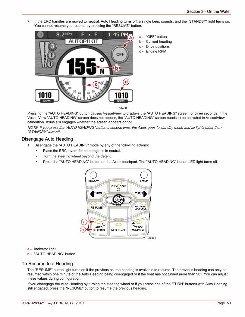
Section 3 - On the Water
90-879288321 eng FEBRUARY 2010 Page 53
7. If the ERC handles are moved to neutral, Auto Heading turns off, a single beep sounds, and the "STANDBY" light turns on.You cannot resume your course by pressing the "RESUME" button.
a - "OFF" buttonb - Current headingc - Drive positionsd - Engine RPM
Pressing the "AUTO HEADING" button causes VesselView to displays the "AUTO HEADING" screen for three seconds. If theVesselView "AUTO HEADING" screen does not appear, the "AUTO HEADING" screen needs to be activated in VesselViewcalibration. Axius still engages whether the screen appears or not.NOTE: If you press the "AUTO HEADING" button a second time, the Axius goes to standby mode and all lights other than"STANDBY" turn off.
Disengage Auto Heading1. Disengage the "AUTO HEADING" mode by any of the following actions:
• Place the ERC levers for both engines in neutral.• Turn the steering wheel beyond the detent.• Press the "AUTO HEADING" button on the Axius touchpad. The "AUTO HEADING" button LED light turns off.
a - Indicator lightb - "AUTO HEADING" button
To Resume to a HeadingThe "RESUME" button light turns on if the previous course heading is available to resume. The previous heading can only beresumed within one minute of the Auto Heading being disengaged or if the boat has not turned more than 90°. You can adjustthese values during configuration.If you disengage the Auto Heading by turning the steering wheel or if you press one of the "TURN" buttons with Auto Headingstill engaged, press the "RESUME" button to resume the previous heading.
31408
b
c
a
d
35561
ab

Section 3 - On the Water
Page 54 90-879288321 eng FEBRUARY 2010
Changing VesselView Mode Display TimesAll modes display a screen on VesselView for three seconds by default. The length of time that a screen is visible inVesselView can be changed from no display at all, display up to 10 seconds, or display the screen until changed.To change the display time:1. Open VesselView.2. Select Setting.3. Select Screen Options.4. Select the mode you want to change.5. Select the option you desire.6. Press × to exit.
Skyhook
! WARNINGA rotating propeller, a moving boat, or a device attached to a moving boat can cause serious injury or death to people in thewater. When Skyhook is engaged, the propellers rotate and the boat moves to maintain the position of the boat. Stop theengines immediately whenever anyone is in the water near the boat.
Skyhook uses GPS and the compass heading information to control the throttle, gear position and steering to maintain theboat's position within approximately 3 m (10 ft).The Skyhook feature can hold your boat nearly stationary, for example, while you wait for a space at the fuel dock, or whilewaiting for a bridge to open. You can also use Skyhook to maintain your boat's position when the water is too deep for ananchor.Skyhook should not be used when the boat is next to a dock, or any other object, including other anchored boats. BecauseSkyhook holds the boat in an approximate position, not a precise one, it can cause your boat to collide with objects close to theboat causing damage to the boat and the nearby objects. Occasionally the Skyhook system may apply a brief surge in powerwhile holding a position. This may cause a person standing near the edge of the boat to lose their balance and fall.To engage Skyhook the drives must be shifted into neutral. However, after engaging Skyhook the drive response is not thesame as with drives normally shifted into neutral. The propellers will turn when Skyhook is activated, and propeller rotation maynot be obvious. As in all boats when the engines are running, it is important to ensure that no one is in the water near the boatand to ensure that passengers are secure. Compliance with this practice is even more important when Skyhook is engaged.Before engaging (activating) Skyhook the operator must:• Inform passengers how Skyhook operates, to stay out of the water and off the swim platform, and to be alert for any
sudden shifts in the boats position.• Check to see no one is on the swim platform, or in the water anywhere near the boat.
When Skyhook is engaged the operator must:• Remain at the helm and maintain a vigilant watch.• Disengage (deactivate) Skyhook if anyone enters the water or approaches the boat from the water.
The capability of most vessels limits the ability of Skyhook to counteract currents of up to 2 knots (2.3 MPH) when the boat issideways to the current. If you notice your boat drifting sideways while Skyhook is engaged, move the bow or stern moredirectly into the current to help reduce the effects of the current.
! WARNINGWhen the Skyhook is engaged, the boat stays in a preset position; however, Skyhook can disengage unexpectedly. WhenSkyhook disengages, the boat does not hold the preset position and may drift, causing the potential of damage or personalinjury. The helm operator must be able to take control of the boat when using Skyhook.
Skyhook relies on an operational GPS receiver and operational heading sensor. Occasionally, due to imperfect satellitecommunications, the GPS signal may be temporarily unavailable. Skyhook will continue to operate through a GPS signaloutage for up to 10 seconds, but disengages if the GPS signal outage persists. If Skyhook disengages, you are alerted by thesound of a horn and the indicator light on the Axius Premier Trackpad for the "SKYHOOK" button turns off. In such acircumstance, the boat will drift with the wind or current because the engines continue to run but the drive units are now inneutral.

Section 3 - On the Water
90-879288321 eng FEBRUARY 2010 Page 55
Skyhook performance is largely dictated by the performance of the onboard Zeus GPS system. The Zeus GPS system isaccurate within 3 meters (10 feet) when receiving a Wide Area Augmentation System (WAAS) correction. WAAS is a system ofsatellites and ground stations that provide GPS signal corrections. When WAAS is not available, the performance of the systemmaintains the boat within 20 meters (60 feet) of the desired position.
Engaging (Activating) SkyhookIMPORTANT: Activities in the water near the vessel while Skyhook is engaged may result in injury. The Captain (or operator)and passengers should read and observe the warning labels on the boat before Skyhook is engaged.
33798
8M0034159
Label adjacent to the Axius Premier CAN Trackpad
33824
Label in the vicinity of the transom boarding area
IMPORTANT: If either of the labels cannot be located or are not legible, they must be replaced before engaging Skyhook.Contact the manufacturer of your boat, your Cummins distributor, or an Authorized Cummins MerCruiser Diesel Repair Facilityand replace the labels.NOTE: Skyhook will not engage while "DOCK" mode is engaged. Disengage "DOCK" mode prior to engaging "SKYHOOK."1. Bring the boat to a stop and move the ERC levers to neutral. Skyhook will not engage until the boat is in neutral.2. Inform passengers to stay out of the water and off the swim platform, and to be alert for any sudden shifts in the boats
position when skyhook is engaged.3. Ensure that no one is on the swim platform, or in the water anywhere near the boat.
! WARNINGA rotating propeller, a moving boat, or a device attached to a moving boat can cause serious injury or death to people in thewater. When Skyhook is engaged, the propellers rotate and the boat moves to maintain the position of the boat. Stop theengines immediately whenever anyone is in the water near the boat.

Section 3 - On the Water
Page 56 90-879288321 eng FEBRUARY 2010
4. Press the "SKYHOOK" button to engage Skyhook.
a - Indicator lightb - "SKYHOOK" button
5. A safety popup (warning screen) appears on VesselView.
33920
Skyhook warning screen on VesselView
6. To acknowledge that you understand the warning on the screen and close the safety popup, press the enter button onVesselView. The enter button is the button with the check mark on it.
7. When the Skyhook system engages, a one second solid horn beep sounds one time. The "SKYHOOK" button light stopsblinking and remains on once Skyhook is engaged.
8. The VesselView "SKYHOOK" screen displays a green circle with the word "ON" when Skyhook engages. See TheSkyhook Screen in VesselView information.
9. When Skyhook is engaged you must remain at the helm and maintain a vigilant watch. Disengage Skyhook if anyoneenters the water or approaches the boat from the water.
10. Press the "SKYHOOK" button a second time to put Axius Premier in standby. All lights other than "STANDBY" turn off.11. To disengage Skyhook, you must choose one of the following methods:
• Press the "SKYHOOK" button on the Axius Premier Trackpad.• Move any ERC lever out of neutral.• Move the joystick.
A single horn beep sounds when the feature disengages. See Disengaging Skyhook for complete details.
The Skyhook Screen in VesselViewIn Skyhook mode VesselView displays a special Skyhook screen. The elements of the Skyhook screen are:• RPM of the engines.• The rotation angle of the boat icon shows the yaw of the boat relative to its position when Skyhook was first engaged.
35570
a
b
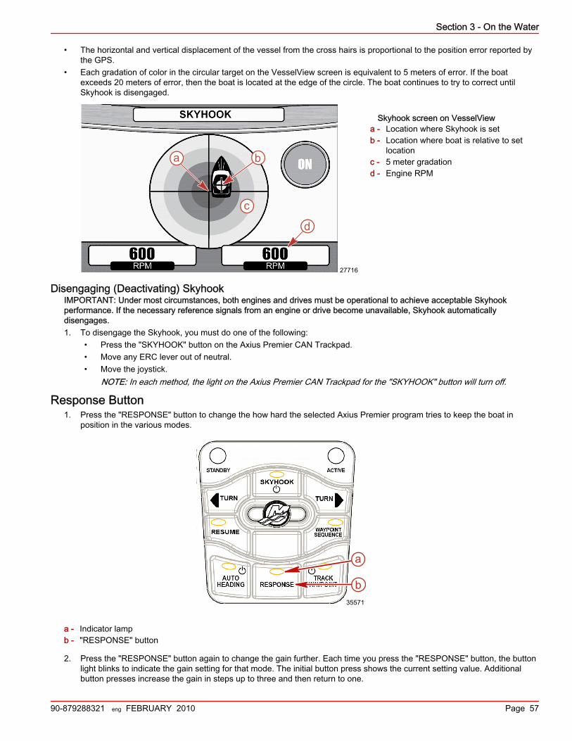
Section 3 - On the Water
90-879288321 eng FEBRUARY 2010 Page 57
• The horizontal and vertical displacement of the vessel from the cross hairs is proportional to the position error reported bythe GPS.
• Each gradation of color in the circular target on the VesselView screen is equivalent to 5 meters of error. If the boatexceeds 20 meters of error, then the boat is located at the edge of the circle. The boat continues to try to correct untilSkyhook is disengaged.
Skyhook screen on VesselViewa - Location where Skyhook is setb - Location where boat is relative to set
locationc - 5 meter gradationd - Engine RPM
Disengaging (Deactivating) SkyhookIMPORTANT: Under most circumstances, both engines and drives must be operational to achieve acceptable Skyhookperformance. If the necessary reference signals from an engine or drive become unavailable, Skyhook automaticallydisengages.1. To disengage the Skyhook, you must do one of the following:
• Press the "SKYHOOK" button on the Axius Premier CAN Trackpad.• Move any ERC lever out of neutral.• Move the joystick.
NOTE: In each method, the light on the Axius Premier CAN Trackpad for the "SKYHOOK" button will turn off.
Response Button1. Press the "RESPONSE" button to change the how hard the selected Axius Premier program tries to keep the boat in
position in the various modes.
a - Indicator lampb - "RESPONSE" button
2. Press the "RESPONSE" button again to change the gain further. Each time you press the "RESPONSE" button, the buttonlight blinks to indicate the gain setting for that mode. The initial button press shows the current setting value. Additionalbutton presses increase the gain in steps up to three and then return to one.
a b
c
d
27716
35571
a
b

Section 3 - On the Water
Page 58 90-879288321 eng FEBRUARY 2010
Number of blinks Response setting indicated Aggressiveness of correction
1 1 Mild (for gentle or calm conditions)
2 2 Medium (for moderate conditions)
3 3 Aggressive (for severe conditions)
3. The response level indication will appear on the Auto Heading page in VesselView.
Track Waypoint
! WARNINGIn some Precision Pilot modes—"Auto Heading," "Track Waypoint," and "Waypoint Sequence"—the boat navigates a presetcourse. The boat does not automatically respond to hazards such as other watercraft, obstacles, swimmers, or underwaterterrain. Collision with these hazards could cause boat damage, serious injury, or death. The operator must stay at the helm,ready to evade hazards and warn others of course changes.
IMPORTANT: Track Waypoint can only be used with chart plotters approved by CMD.Track Waypoint allows the boat to automatically navigate to a specific waypoint or sequence of waypoints, called a waypointroute. Waypoint data needs to be provided to VesselView by a third party chart plotter. Refer to your chart plotter's user manualfor details.
Engaging Track Waypoint ModeTo engage the Track Waypoint mode of Axius Premier:1. Turn on the chart plotter and select a single waypoint or waypoint route to be tracked.2. Place at least one ERC handle in forward gear. Track Waypoint does not function if both handles are in neutral or reverse.3. Manually steer the boat to the direction of the first waypoint and hold the boat steady at a safe operating speed.4. Press the "TRACK WAYPOINT" button on the Axius Premier Trackpad. The "TRACK WAYPOINT" button light turns on
and a single horn beep sounds, indicating Track Waypoint engaged. Track Waypoint tracks to the first waypoint on thechart plotter course. Two horn beeps sound if Track Waypoint does not engage.
a - Indicator lampb - "TRACK WAYPOINT" button
5. The VesselView "TRACK WAYPOINT" screen displays on VesselView for one second after pressing the "TRACKWAYPOINT" button. The display shows the digital heading that the boat is traveling, the angles of the drives, and enginespeed in RPM. See Mode Display in VesselView.
35572
ab

Section 3 - On the Water
90-879288321 eng FEBRUARY 2010 Page 59
NOTE: This display screen is activated during VesselView calibration. The GPS system generates the displayed headingbased on magnetic North.
31413
Track Waypoint screen
Disengaging Track Waypoint Mode1. Disengage the Track Waypoint mode by one of the following methods:
• Press the "TRACK WAYPOINT" button on the Axius Premier Trackpad. The "TRACK WAYPOINT" button light goesoff and Axius Premier goes to Standby. The "STANDBY" light turns on
• Turn the steering wheel hard enough to overcome the detent and Axius Premier features go into Standby.• Move both ERC levers back to neutral and Axius Premier goes to Standby.• Press either "TURN" button and Axius Premier goes to Auto Heading mode.• Press the "AUTO HEADING" button and Axius Premier CAN Trackpad goes to Auto Heading mode.• Turn off the chart plotter and Axius Premier goes to Standby.
2. You can resume the Track Waypoint heading within one minute, if the vessel has not turned too far and the "RESUME"light is still on or flashing.
Turn Buttons or Joystick in Track Waypoint ModeWhile in "TRACK WAYPOINT" mode, press the left or right "TURN" buttons on the Trackpad or use the joystick to change themode to "AUTO HEADING."
Auto Heading Button in Track Waypoint ModeWhile in "TRACK WAYPOINT" mode, press the "AUTO HEADING" button to cause Axius Premier to change to "AUTOHEADING" mode.
Acknowledging a Turn During a Waypoint ArrivalIMPORTANT: Track Waypoint mode does not automatically turn the boat upon arrival at a plotted waypoint.

Section 3 - On the Water
Page 60 90-879288321 eng FEBRUARY 2010
1. When the boat enters a waypoint arrival zone as indicated by the chart plotter, a short horn beep sounds and the"WAYPOINT SEQUENCING" button light starts blinking to inform the operator to make a turn.
a - Indicator lightb - "WAYPOINT SEQUENCE" button
2. If the Waypoint Sequence mode has not been engaged, the "WAYPOINT SEQUENCE" icon light blinks at the arrival zone.
31411
Waypoint Sequence icon light
35575
ab

Section 3 - On the Water
90-879288321 eng FEBRUARY 2010 Page 61
3. VesselView displays a pop‑up screen warning. The operator must determine it is safe to turn the boat. If so, press the"WAYPOINT SEQUENCE" button to acknowledge that it is safe for Axius Premier CAN Trackpad to automatically turn theboat and maneuver to the new course.
31414
Pop-up screen warning
4. If the waypoint is not acknowledged, the boat continues on its current heading.5. At the end of the Track Waypoint course, input a new route or take control of the boat. Otherwise, the boat will revert to
auto heading mode and continues on its last course heading.
Waypoint Sequence1. Place the ERC lever or levers into forward. "WAYPOINT SEQUENCE" does not engage if the levers are in neutral or
reverse.2. If the Track Waypoint button light is not on, press the "TRACK WAYPOINT" button.3. Press the "WAYPOINT SEQUENCE" button to engage Waypoint Sequence mode. The indicator light on the button will
illuminate.
a - Indicator lampb - "WAYPOINT SEQUENCE" button
35575
ab

Section 3 - On the Water
Page 62 90-879288321 eng FEBRUARY 2010
4. A horn beep sounds on VesselView and the green circle icon on the Axius Premier screen will display "TRACK." The"TRACK" icon on the VesselView screen should illuminate.
31411
Waypoint Sequence TRACK icon
5. If you are in a waypoint arrival zone set by the chart plotter, Waypoint Sequence mode only informs Axius Premier it is OKto proceed to next waypoint. Waypoint Sequence mode acts as a waypoint acknowledge function and Axius Premiersounds a horn beep when in the zone.
! WARNINGIn some Precision Pilot modes—"Auto Heading," "Track Waypoint," and "Waypoint Sequence"—the boat navigates a presetcourse. The boat does not automatically respond to hazards such as other watercraft, obstacles, swimmers, or underwaterterrain. Collision with these hazards could cause boat damage, serious injury, or death. The operator must stay at the helm,ready to evade hazards and warn others of course changes.
6. Press the enter button to acknowledge it is OK to turn. The enter button is in the upper right corner of VesselView and hasa check mark symbol. Once acknowledged, Axius Premier Trackpad tracks to the next waypoint in the route.
7. Stay alert; the boat turns automatically in this mode. The operator must know if it is safe to turn when the vessel is enteringa waypoint arrival zone. Inform passengers that the boat automatically turns so they can be prepared.
31414
Waypoint acknowledge screen

Section 3 - On the Water
90-879288321 eng FEBRUARY 2010 Page 63
8. If you are not in a previously set waypoint arrival zone, "WAYPOINT SEQUENCE" mode starts auto sequencing to thewaypoints in the route. Acknowledge that you understand the information presented by the pop‑up screen warning andpress the enter button—the button with a check mark symbol.
31412
Pop-up screen warning
9. Press the "TRACK WAYPOINT" button. The "WAYPOINT SEQUENCE" button light turns on and a single horn beepsounds.
10. Press the "TRACK WAYPOINT" button a second time to put Axius Premier in Standby mode. All lights other than"STANDBY" turn off.
Cruise ControlThe VesselView system features integrated throttle cruise control (cruise), which allows the operator to limit the peak RPM ofchoice below Wide Open Throttle (WOT). This feature requires VesselView. Refer to the owner's manual provided with yourVesselView for operation instructions.These additional notes are exclusive to your package:• You can change or disengage cruise through the screen at any time.• Cruise resets when the key is turned off.• If the cruise limit is changed while the levers are at WOT, cruise gradually changes to the new speed.• Cruise does not disengage if the ERC levers are at a higher engine speed than the actual RPM. Bring the levers back to
the forward detent to disengage.
Contingent OperationsPort Engine–Only Operation
The force feedback feature of the steering wheel is only available when the starboard key switch is in the on position. If thestarboard key switch is off or there has been damage to the starboard electrical system, the port control system monitors thesteering wheel.If only the port side is operational, or only the port key switch is in the on position, the force feedback system will not provideend stops for the steering wheel. In this case, the drive will turn in the direction of steering wheel rotation until the mechanicallimits of the drive are reached.NOTE: If the port electrical system is damaged, the steering wheel will operate normally with complete force feedback and endstops.Note that joystick is not available in single‑engine operation. However, Axius features redundant trackpad systems, so AutoHeading mode is still available during single‑engine operation.
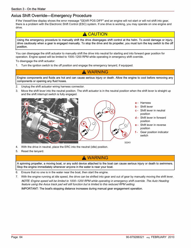
Section 3 - On the Water
Page 64 90-879288321 eng FEBRUARY 2010
Axius Shift Override—Emergency ProcedureIf the VesselView display shows the error message "GEAR POS DIFF" and an engine will not start or will not shift into gear,there is a problem with the Electronic Shift Control (ESC) system. If one drive is working, you may operate on one engine anddrive.
! CAUTIONUsing the emergency procedure to manually shift the drive disengages shift control at the helm. To avoid damage or injury,drive cautiously when a gear is engaged manually. To stop the drive and its propeller, you must turn the key switch to the offposition.
You can disengage the shift actuator to manually shift the drive into neutral for starting and into forward gear position foroperation. Engine speed will be limited to 1000–1200 RPM while operating in emergency shift override.To disengage the shift actuator:1. Turn the ignition switch to the off position and engage the emergency lanyard, if equipped.
! WARNINGEngine components and fluids are hot and can cause serious injury or death. Allow the engine to cool before removing anycomponents or opening any fluid hoses.
2. Unplug the shift actuator wiring harness connector.3. Move the shift lever into the neutral position. The shift actuator is in the neutral position when the shift lever is straight up
and the shift interrupt switch is fully engaged.
a - Harnessb - Shift leverc - Shift lever in neutral
positiond - Shift lever in forward
positione - Shift lever in reverse
positionf - Gear position indicator
switch
4. With the drive in neutral, place the ERC into the neutral (idle) position.5. Reset the lanyard.
! WARNINGA spinning propeller, a moving boat, or any solid device attached to the boat can cause serious injury or death to swimmers.Stop the engine immediately whenever anyone in the water is near your boat.
6. Ensure that no one is in the water near the boat, then start the engine.7. With the engine running at idle speed, the drive can be shifted into gear and out of gear by manually moving the shift lever.
NOTE: Engine speed will be limited to 1000–1200 RPM while operating in emergency shift override. The Auto Headingfeature using the Axius track pad will still function but is limited to this reduced RPM setting.IMPORTANT: The boat's stopping distance increases during manual gear engagement operation.
N
FR
a
b
d
e
32243
f
c
YY
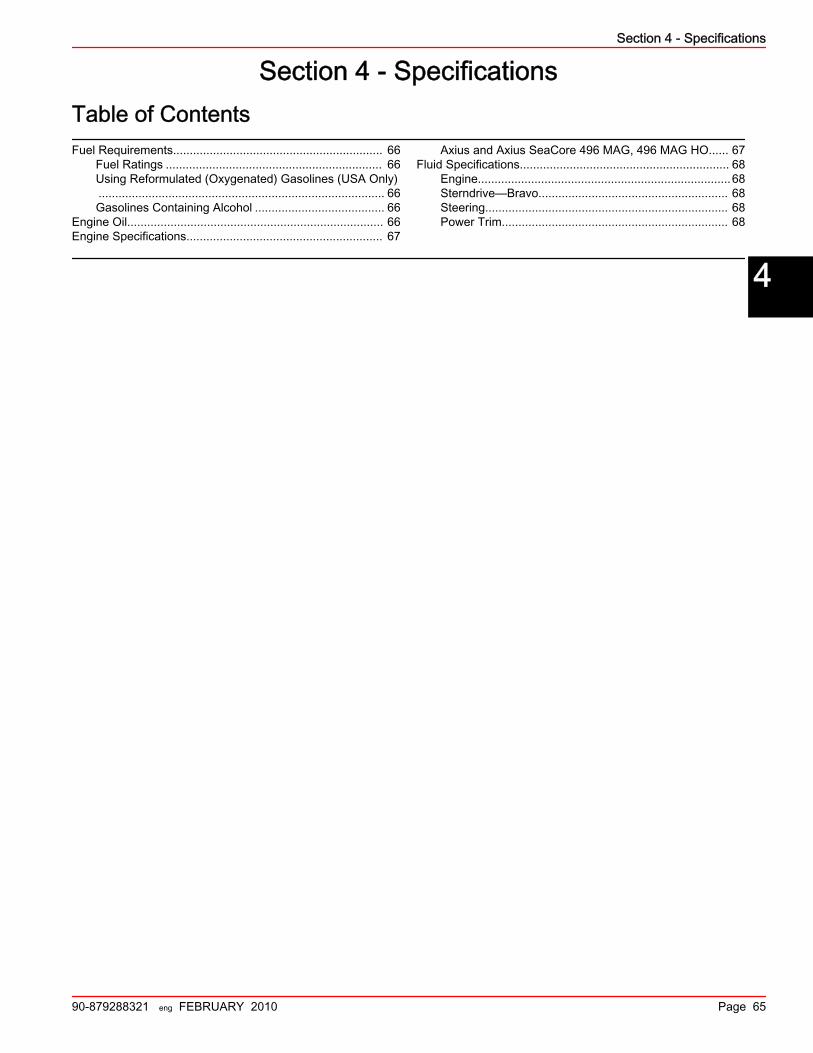
Section 4 - Specifications
90-879288321 eng FEBRUARY 2010 Page 65
Section 4 - SpecificationsTable of ContentsFuel Requirements............................................................... 66
Fuel Ratings ................................................................. 66Using Reformulated (Oxygenated) Gasolines (USA Only)...................................................................................... 66Gasolines Containing Alcohol ....................................... 66
Engine Oil............................................................................. 66Engine Specifications........................................................... 67
Axius and Axius SeaCore 496 MAG, 496 MAG HO...... 67Fluid Specifications............................................................... 68
Engine............................................................................68Sterndrive—Bravo......................................................... 68Steering......................................................................... 68Power Trim.................................................................... 68
4

Section 4 - Specifications
Page 66 90-879288321 eng FEBRUARY 2010
Fuel RequirementsIMPORTANT: Use of improper gasoline can damage your engine. Engine damage resulting from the use of impropergasoline is considered misuse of the engine and any resulting damage will not be covered under the limited warranty.
Fuel RatingsMercury MerCruiser engines will operate satisfactorily when using a major brand of unleaded gasoline meeting the followingspecifications:USA and Canada—having a posted pump Octane Rating of 87 (R+M)/2 minimum. Premium gasoline 92 (R+M)/2 Octane isalso acceptable. Do not use leaded gasoline.Outside USA and Canada—having a posted pump Octane Rating of 91 RON minimum. Premium gasoline (98 RON) is alsoacceptable. If unleaded gasoline is not available, use a major brand of leaded gasoline.
Using Reformulated (Oxygenated) Gasolines (USA Only)This type of gasoline is required in certain areas of the USA. The 2 types of oxygenates used in these fuels is alcohol (ethanol)or ether (MTBE or ETBE). If Ethanol is the oxygenate that is used in the gasoline in your area, refer to Gasolines ContainingAlcohol.These reformulated gasolines are acceptable for use in your Mercury MerCruiser engine.
Gasolines Containing AlcoholIf the gasoline in your area contains either methanol (methyl alcohol) or ethanol (ethyl alcohol), you should be aware of certainadverse effects that can occur. These adverse effects are more severe with methanol. Increasing the percentage of alcohol inthe fuel can also worsen these adverse effects.Some of these adverse effects are caused because the alcohol in the gasoline can absorb moisture from the air, resulting in aseparation of the water‑alcohol mixture from the gasoline in the fuel tank.The fuel system components on your Mercury MerCruiser engine will withstand up to 10% alcohol content in the gasoline. Wedo not know what percentage your boat's fuel system will withstand. Contact your boat manufacturer for specificrecommendations on the boat's fuel system components (fuel tanks, fuel lines, and fittings). Be aware that gasolines containingalcohol may increase:• Corrosion of metal parts• Deterioration of rubber or plastic parts• Fuel permeation through the rubber fuel lines• Difficulty starting and operating the engine
! WARNINGFuel leakage is a fire or explosion hazard, which can cause serious injury or death. Periodically inspect all fuel systemcomponents for leaks, softening, hardening, swelling, or corrosion, particularly after storage. Any sign of leakage ordeterioration requires replacement before further engine operation.
Because of the possible adverse effects of alcohol in gasoline, we recommend only alcohol‑free gasoline when possible. If theonly fuel available contains alcohol or if you do not know whether the fuel contains alcohol, inspect for leaks and abnormalitiesmore frequently.IMPORTANT: When operating a Mercury MerCruiser engine on gasoline containing alcohol, do not store the gasoline in thefuel tank for long periods. Cars normally consume alcohol‑blend fuels before they can absorb enough moisture to causetrouble, boats often sit idle long enough for phase separation to take place. Internal corrosion may take place during storage ifalcohol has washed protective oil films from internal components.
Engine OilTo help obtain optimum engine performance and to provide maximum protection, we recommend using the following oil:
Application Recommended Oil
All MerCruiser engines Mercury MerCruiser Full‑Synthetic Engine Oil, 20W‑40, NMMA FC‑W rated
If the Mercury MerCruiser Full‑Synthetic, 20W‑40 oil is unavailable, you can use the following lubricants, listed in order ofrecommendation:1. Mercury/Quicksilver 25W‑40 Synthetic Blend, NMMA FC‑W–rated 4‑cycle MerCruiser oil2. Mercury/Quicksilver 25W‑40, NMMA FC‑W–rated 4‑cycle MerCruiser oil3. Other recognized brands of NMMA FC‑W–rated 4‑cycle oils

Section 4 - Specifications
90-879288321 eng FEBRUARY 2010 Page 67
4. A good‑grade, straight‑weight detergent automotive oil per the operating chart below.NOTE: We do not recommend non‑detergent oils, multi‑viscosity oils (other than as specified), non FC‑W–rated synthetic oils,low‑quality oils, or oils that contain solid additives.
Mercury Full-Synthetic MerCruiser Engine Oil, 20W-40, NMMA FC-W rated
MerCruiser/Quicksilver 25W-40 Synthetic Blend, NMMA FC-W rated 4-cycle MerCruiser oil
Other recognized brands of NMMA FC-W rated oils
SAE 20W
SAE30W
SAE40W
AIR TEMPERATURE
OR
DE
R O
F P
RE
FER
EN
CE
(32° F) 0° C
(50° F)10° C
32878
Mercury/Quicksilver 25W-40, NMMA FC-W rated 4-cycle MerCruiser oil
Engine SpecificationsAxius and Axius SeaCore 496 MAG, 496 MAG HO
NOTE: Performance specifications are obtained and corrected in accordance with SAE J1228/ISO 8665 Crankshaft Power.All measurements are taken with the engine at normal operating temperature.RPM range is measured using an accurate service tachometer with the engine at normal operating temperatures.Oil pressure must be checked with the engine at normal operating temperature.NOTE: Oil pressure specifications are for reference and may vary.

Section 4 - Specifications
Page 68 90-879288321 eng FEBRUARY 2010
496 MAG 496 MAG HO
Propshaft power 280 kW (375 hp) 317 kW (425 hp)
Displacement 8.1 L (496 cid)
Alternator amperageHot 72 A
Cold 65 A
RPMWOT 4400–4800 4600–5000
Rev limiter 4950 5150
Idle RPMMechanical 600
DTS (including Axius) 575 625
Minimum oil pressure At 2000 RPM 207 kPa (30 psi)
At idle 103 kPa (15 psi)
Thermostat MPI models with closed cooling 77° C (170° F)
Timing at idle Not Adjustable
Firing order 1‑8‑7‑2‑6‑5‑4‑3
Minimum battery ratingNon‑DTS models 750 CCA, 950 MCA, 180 Ah
DTS models 800 CCA, 1000 MCA, 190 Ah
Spark plug type AC Platinum (AC 41‑983)
Spark plug gap 1.5 mm (0.060 in.)
Emission Control System Electronic engine control (EC)
Fluid SpecificationsIMPORTANT: All capacities are approximate fluid measures.
EngineIMPORTANT: All capacities are approximate fluid measures.
All Models Capacity Fluid Type
Engine oil (with filter) 8.5 L (9 US qt) Mercury Full‑Synthetic MerCruiser Engine Oil 20W‑40
Seawater cooling system (winterizationuse only) 20 L (21 US qt) Propylene glycol and purified water
Closed cooling system 18 L (19 US qt) Mercury Extended Life Coolant Antifreeze or extended lifeethylene glycol 5/100 antifreeze mixed 50/50 with purified water
Sterndrive—BravoNOTE: Oil capacity includes gear lube monitor.
Model Capacity Fluid Type
Bravo Three with dual water pickups 2736 mL (92‑1/2 oz)High Performance Gear Lubricant
Bravo Three with side water pickups only 2972 mL (100‑1/2 oz)
SteeringAxius—All Models Capacity Fluid Type
Steering system 2914 mL (98‑1/2 oz) Dexron III
Power TrimDescription Part Number
Power Trim and Steering Fluid 92‑858074K01

Section 4 - Specifications
90-879288321 eng FEBRUARY 2010 Page 69
Description Part Number
SAE Engine Oil 10W‑30Obtain locally
SAE Engine Oil 10W‑40

Section 4 - Specifications
Notes:
Page 70 90-879288321 eng FEBRUARY 2010

Section 5 - Maintenance
90-879288321 eng FEBRUARY 2010 Page 71
Section 5 - MaintenanceTable of ContentsOwner/Operator Responsibilities.......................................... 72Dealer Responsibilities......................................................... 72Maintenance......................................................................... 72Do‑It‑Yourself Maintenance Suggestions............................. 72Inspection............................................................................. 73Maintenance Schedules—Axius Models.............................. 73
Routine Maintenance—Axius Models............................ 73Scheduled Maintenance—Axius Models....................... 73
Maintenance Log.................................................................. 74Engine Oil............................................................................. 75
Checking........................................................................ 75Filling............................................................................. 76Changing Oil and Filter.................................................. 76Engine Oil Drain Pump.................................................. 77Changing Filter.............................................................. 77
Steering Fluid....................................................................... 78Checking and Filling Steering Fluid............................... 78Changing Steering Fluid................................................ 78
Closed Cooling System........................................................ 78Coolant Requirement..................................................... 78Checking Coolant Level................................................. 79
.............................................................................. 79Filling the Closed Cooling System................................. 79Draining......................................................................... 80Cleaning.........................................................................80
Sterndrive Gear Lube........................................................... 80Checking........................................................................ 80Filling............................................................................. 81Changing....................................................................... 81
Power Trim Fluid.................................................................. 83Checking ....................................................................... 83Filling ............................................................................ 83Changing ...................................................................... 83
Battery.................................................................................. 83Multiple EFI Engine Battery Precautions....................... 84
Cleaning the Flame Arrestor................................................. 84Water‑Separating Fuel Filter ............................................... 85
GEN III Models.............................................................. 86Removal ................................................................ 86Installation ............................................................. 86
Lubrication............................................................................ 87Electronic Shift Control (ESC) Shift Cable..................... 87Sterndrive Unit and Transom Assembly........................ 87Sterndrive U‑Joint Shaft Splines and O‑Rings (SterndriveUnit Removed)............................................................... 88Engine Coupler.............................................................. 88
Propellers............................................................................. 88Propeller Repair............................................................. 88Bravo Three Propeller Removal.................................... 89Bravo Three Propeller Installation................................. 90
Serpentine Drive Belt............................................................ 91Checking........................................................................ 91Replacing....................................................................... 92
Corrosion Protection............................................................. 93Corrosion Information.................................................... 93Maintaining Ground Circuit Continuity........................... 93MerCathode System Battery Requirements.................. 93Anodes and MerCathode System Locations................. 93Checking the Quicksilver MerCathode System............. 94Power Package Exterior Surfaces................................. 95Boat Bottom Care.......................................................... 95Antifouling Paint............................................................. 95Sterndrive Surface Care................................................ 97
Flushing the Seawater System—Sterndrive Models............ 97General Information—Bravo Sterndrive.........................97
Flushing Attachments ............................................ 98Sterndrive Water Pickups ...................................... 98
Boat Out of the Water—Bravo Sterndrive......................98Boat in the Water—Bravo Sterndrive.............................99Boat Out of the Water—Alternative Water Pickups..... 100Boat in the Water—Alternative Water Pickups............ 100SeaCore Power Package Flushing Procedure............ 101
Models Using The Sterndrive Water Pickup ........ 101
5

Section 5 - Maintenance
Page 72 90-879288321 eng FEBRUARY 2010
Owner/Operator ResponsibilitiesIt is the operator's responsibility to perform all safety checks, to ensure that all lubrication and maintenance instructions arecomplied with for safe operation and to return the unit to an authorized Mercury MerCruiser dealer for a periodic checkup.Normal maintenance service and replacement parts are the responsibility of the owner/operator and as such, are notconsidered defects in workmanship or material within the terms of the warranty. Individual operating habits and usagecontribute to the need for maintenance service.Proper maintenance and care of your power package will ensure optimum performance and dependability and will keep youroverall operating expenses at a minimum. See your authorized Mercury MerCruiser dealer for service aids.
Dealer ResponsibilitiesIn general, a dealer's responsibilities to the customer include predelivery inspection and preparation such as:• Ensure that the boat is properly equipped.• Prior to delivery, make certain that the Mercury MerCruiser power package and other equipment are in proper operating
condition.• Make all necessary adjustments for maximum efficiency.• Familiarize the customer with the on‑board equipment.• Explain and demonstrate the operation of the power package and boat.• Provide you with a copy of a Predelivery Inspection Checklist.• Your selling dealer should fill out the Warranty Registration Card completely and mail it to the factory immediately upon
sale of the new product.
Maintenance! WARNING
Performing service or maintenance without first disconnecting the battery can cause product damage, personal injury, ordeath due to fire, explosion, electrical shock, or unexpected engine starting. Always disconnect the battery cables from thebattery before maintaining, servicing, installing, or removing engine or drive components.
! WARNINGFuel vapors trapped in the engine compartment may be an irritant, cause difficulty breathing, or may ignite resulting in a fireor explosion. Always ventilate the engine compartment before servicing the power package.
IMPORTANT: Refer to the maintenance schedule for the complete listing of all scheduled maintenance to be performed. Arepair shop or person of the owner's choosing may maintain, replace, or repair emission control devices and systems. Certainother items should be performed only by an authorized Mercury MerCruiser dealer. Before attempting maintenance or repairprocedures not covered in this manual, we recommend that you purchase a Mercury MerCruiser service manual and read itthoroughly.NOTE: Maintenance points are color‑coded for ease of identification.
Maintenance Point Color Codes
Yellow Engine oil
Black Drive lube
Brown Power steering fluid
Blue Drain or flush
Do‑It‑Yourself Maintenance SuggestionsPresent day marine equipment, such as your Mercury MerCruiser power package, are highly technical pieces of machinery.Electronic ignition and special fuel delivery systems provide greater fuel economies, but also are more complex for theuntrained mechanic.If you are one of those persons who likes to do it yourself, here are some suggestions for you.• Do not attempt any repairs unless you are aware of the Cautions, Warnings and procedures required. Your safety is our
concern.

Section 5 - Maintenance
90-879288321 eng FEBRUARY 2010 Page 73
• If you attempt to service the product yourself, we suggest you order the service manual for that model. The service manualoutlines the correct procedures to follow. It is written for the trained mechanic, so there may be procedures you don'tunderstand. Do not attempt repairs if you do not understand the procedures.
• There are special tools and equipment that are required to perform some repairs. Do not attempt these repairs unless youhave these special tools and/or equipment. You can cause damage to the product in excess of the cost a dealer wouldcharge you.
• Also, if you partially disassemble an engine or drive assembly and are unable to repair it, the dealer's mechanic mustreassemble the components and test to determine the problem. This will cost you more than taking it to the dealerimmediately upon having a problem. It may be a very simple adjustment to correct the problem.
• Do not telephone the dealer, service office or the factory to attempt for them to diagnose a problem or to request the repairprocedure. It is difficult for them to diagnose a problem over the telephone.
Your authorized dealer is there to service your power package. They have qualified factory trained mechanics.It is recommended you have the dealer do periodic maintenance checks on your power package. Have them winterize it in thefall and service it before the boating season. This will reduce the possibility of any problems occurring during your boatingseason when you want trouble free boating pleasure.
InspectionInspect your power package often, and at regular intervals, to help maintain its top operating performance and correct potentialproblems before they occur. The entire power package should be checked carefully, including all accessible engine parts.• Check for loose, damaged or missing parts, hoses and clamps; tighten or replace as necessary.• Check plug leads and electrical leads for damage.• Remove and inspect the propeller. If badly nicked, bent or cracked, contact your authorized Mercury MerCruiser dealer.• Repair nicks and corrosion damage on power package exterior finish. Contact your authorized Mercury MerCruiser dealer.
Maintenance Schedules—Axius ModelsRoutine Maintenance—Axius Models
NOTE: Only perform maintenance that applies to your particular power package.
Task Interval Maintenance to Be Performed
Each day start
• Check the engine oil level. (You can extend this interval based on experience with theproduct.)
• Check the sterndrive gear lube level.• Check the trim pump oil level.• Check the power steering pump fluid level.
Each day end• If operating in saltwater, brackish water, or polluted water, flush the seawater section of the
cooling system after each use.
Weekly
• Check the water inlets for debris or marine growth.• Check and clean the seawater strainer, if equipped.• Check the coolant level.• Inspect the sterndrive anodes and replace if 50% eroded.
Every two months or 50hours
• Lubricate the propeller shafts and tighten the propeller nuts to specifications. (If operatingonly in freshwater, you can extend the interval to four months.)
• If operating in saltwater, brackish water, or polluted water, apply Corrosion Guard to thepower package.
• Check the battery connections and the fluid level.• Ensure that the gauges and the wiring connections are secure. Clean the gauges. (If
operating in saltwater, reduce this interval to 25 hours or 30 days, whichever occurs first.)
Scheduled Maintenance—Axius ModelsNOTE: Only perform maintenance that applies to your particular power package.

Section 5 - Maintenance
Page 74 90-879288321 eng FEBRUARY 2010
Task Interval Maintenance to Be Performed
After the first 20 hoursand not to exceed 25
hours
• Change the engine oil and filter.• Check and adjust the serpentine belt tension.
Every 100 hours orannually
(whichever occurs first)
• Touch up the paint on the power package.• Change the engine oil and filter.• Change the sterndrive gear lube.• If the condition of the spark plugs, spark plug wires, and the distributor cap and rotor was
satisfactory at the initial inspection (as listed in Every 300 hours or 3 years), inspect thecondition of these components. Replace as necessary.
• Tighten the connection of the gimbal ring to the steering shaft to specifications.• Replace the water‑separating fuel filter element.• Check the steering system and the remote control for loose, missing, or damaged parts.
Lubricate the cables and the linkages.• Check the continuity circuit for loose or damaged connections. If the package is equipped
with a MerCathode, test the MerCathode unit output.• Clean the flame arrestor, IAC muffler (MPI engines), and the crankcase ventilation hoses.
Inspect the PCV valve (if equipped) and replace if needed.• Inspect the condition and the tension of the belts.• Check the coolant level and antifreeze concentration for adequate freeze protection. Correct
if necessary. Refer to the Specifications section.
Every 200 hours or 3years
• Inspect the U‑joints, the splines, and the bellows. Check the clamps.• Check the engine alignment.• Lubricate the U‑joint splines and cross bearing, if equipped with grease fittings.• Lubricate the gimbal bearing and the engine coupler.
NOTE: Lubricate the engine coupler every 50 hours if operated at idle for prolonged periods oftime.
Every 300 hours or 3years
• Check the engine mounts for tightness and tighten to specifications if necessary.• Inspect the condition of the spark plugs, spark plug wires, and the distributor cap and rotor, if
equipped. Replace as necessary. If the condition of these components is satisfactory atinspection, repeat inspection every 100 hours or once a year, whichever occurs first.
• Check the electrical system for loose, damaged, or corroded fasteners.• Check the cooling system and the exhaust system hose clamps for tightness. Inspect both
systems for damage or leaks.• Disassemble and inspect the seawater pump and replace worn components.• Clean the seawater section of the closed‑cooling system. Clean, inspect, and test the
pressure cap.• Inspect the exhaust system components. If the package was equipped with water shutters
(flapper valves), verify that they are not missing or worn.
Every 5 years• Replace the coolant/anitifreeze. Replace every two years if not using extended‑life coolant/
antifreeze.
Maintenance LogRecord all maintenance performed on your power package here. Be sure to save all work orders and receipts.
Date Maintenance Performed Engine Hours

Section 5 - Maintenance
90-879288321 eng FEBRUARY 2010 Page 75
Date Maintenance Performed Engine Hours
Engine OilChecking
NOTICEDischarge of oil, coolant, or other engine/drive fluids into the environment is restricted by law. Use caution not to spill oil,coolant, or other fluids into the environment when using or servicing your boat. Be aware of the local restrictions governingthe disposal or recycling of waste, and contain and dispose of fluids as required.
1. Stop the engine. Allow approximately 5 minutes for the oil to drain into the oil pan. The boat must be at rest in the water.2. Remove the dipstick. Wipe clean and reinstall fully into the dipstick tube. Wait 60 seconds to allow trapped air to vent.

Section 5 - Maintenance
Page 76 90-879288321 eng FEBRUARY 2010
NOTE: Ensure that dipstick is installed with oil level indication marks facing the rear of the engine (flywheel end).
a - Dipstick tube
IMPORTANT: Add the specified engine oil to bring the level up to, but not over, the full or OK range mark on the dipstick.3. Remove the dipstick and observe the oil level. Oil level must be between full or OK range and add. Reinstall dipstick into
dipstick tube.
FillingIMPORTANT: Do not overfill the engine with oil.IMPORTANT: Always use the dipstick to determine the exact quantity of oil or fluid required.1. Remove oil fill cap.
a - Oil fill cap
IMPORTANT: Add the specified engine oil to bring the level up to, but not over, the full or OK range mark on the dipstick.2. Add the specified engine oil to bring the level up to, but not over, the full or OK range mark on the dipstick. Recheck oil
level.3. Replace the fill cap.
All Models Capacity Fluid Type
Engine oil (with filter) 8.5 L (9 US qt) Mercury MerCruiser Full‑Synthetic Engine Oil, 20W‑40
Changing Oil and FilterRefer to the Maintenance schedule for the change interval. Engine oil should be changed before placing the boat in storage.
8481
a
a
5581

Section 5 - Maintenance
90-879288321 eng FEBRUARY 2010 Page 77
IMPORTANT: Change engine oil when the engine is warm from operation. Warm oil flows more freely, carrying away moreimpurities. Use only recommended engine oil (refer to Specifications).
Engine Oil Drain Pump1. Loosen the oil filter to vent the system.2. Remove the dipstick.3. Install the oil pump onto the dipstick tube.
a - Typical oil pumpb - Dipstick tubec - Oil drain hose
4. Insert the hose end of the crankcase oil pump onto an appropriate container and, using the handle, pump until thecrankcase is empty.
5. Remove the pump.6. Install the dipstick.
Changing Filter1. Remove and discard oil filter.
a - Oil filter
2. Coat sealing ring on new filter with engine oil and install.3. Tighten oil filter securely (following filter manufacturer's instructions). Do not overtighten.4. Remove oil fill cap.
IMPORTANT: Always use dipstick to determine exactly how much oil is required.5. Add recommended engine oil to bring level up to the bottom of the OK range on the dipstick.6. With the boat at rest in the water, check the oil level and add specified fluid to bring the oil level up to, but not over, the full
or OK range.NOTE: Adding 0.95 L (1 qt) of engine oil will raise the level from the add mark to the top of the OK range.
mc70571-1
a
cb
8483
a
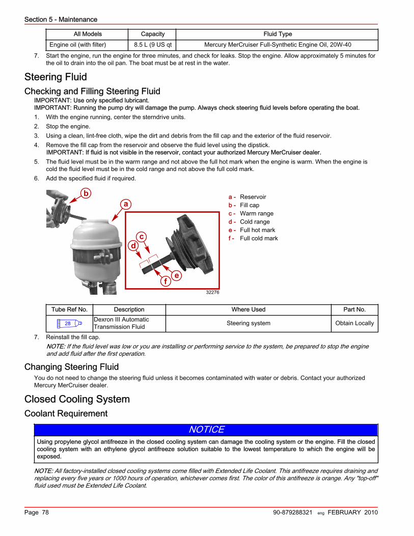
Section 5 - Maintenance
Page 78 90-879288321 eng FEBRUARY 2010
All Models Capacity Fluid Type
Engine oil (with filter) 8.5 L (9 US qt Mercury MerCruiser Full‑Synthetic Engine Oil, 20W‑40
7. Start the engine, run the engine for three minutes, and check for leaks. Stop the engine. Allow approximately 5 minutes forthe oil to drain into the oil pan. The boat must be at rest in the water.
Steering FluidChecking and Filling Steering Fluid
IMPORTANT: Use only specified lubricant.IMPORTANT: Running the pump dry will damage the pump. Always check steering fluid levels before operating the boat.1. With the engine running, center the sterndrive units.2. Stop the engine.3. Using a clean, lint‑free cloth, wipe the dirt and debris from the fill cap and the exterior of the fluid reservoir.4. Remove the fill cap from the reservoir and observe the fluid level using the dipstick.
IMPORTANT: If fluid is not visible in the reservoir, contact your authorized Mercury MerCruiser dealer.5. The fluid level must be in the warm range and not above the full hot mark when the engine is warm. When the engine is
cold the fluid level must be in the cold range and not above the full cold mark.6. Add the specified fluid if required.
a - Reservoirb - Fill capc - Warm ranged - Cold rangee - Full hot markf - Full cold mark
Tube Ref No. Description Where Used Part No.
28Dexron III AutomaticTransmission Fluid Steering system Obtain Locally
7. Reinstall the fill cap.NOTE: If the fluid level was low or you are installing or performing service to the system, be prepared to stop the engineand add fluid after the first operation.
Changing Steering FluidYou do not need to change the steering fluid unless it becomes contaminated with water or debris. Contact your authorizedMercury MerCruiser dealer.
Closed Cooling SystemCoolant Requirement
NOTICEUsing propylene glycol antifreeze in the closed cooling system can damage the cooling system or the engine. Fill the closedcooling system with an ethylene glycol antifreeze solution suitable to the lowest temperature to which the engine will beexposed.
NOTE: All factory‑installed closed cooling systems come filled with Extended Life Coolant. This antifreeze requires draining andreplacing every five years or 1000 hours of operation, whichever comes first. The color of this antifreeze is orange. Any "top‑off"fluid used must be Extended Life Coolant.
ab
cd
32276
fe

Section 5 - Maintenance
90-879288321 eng FEBRUARY 2010 Page 79
Tube Ref No. Description Where Used Part No.
122Extended Life Antifreeze/Coolant Closed cooling system 92-877770K1
Checking Coolant Level
! CAUTIONA sudden loss of pressure can cause hot coolant to boil and discharge violently resulting in serious injury from burns. Allowthe engine to cool down before removing the coolant pressure cap.
IMPORTANT: When reinstalling the pressure cap, ensure that it is tightened securely.1. The coolant level should be at the "FULL" mark on the coolant reservoir with the engine cold.
a - Coolant reservoir
Filling the Closed Cooling SystemIMPORTANT: The engine must be cooled to ambient temperature to correctly perform the following procedure.
NOTICEUsing propylene glycol antifreeze in the closed cooling system can damage the cooling system or the engine. Fill the closedcooling system with an ethylene glycol antifreeze solution suitable to the lowest temperature to which the engine will beexposed.
The coolant section of the closed cooling system must be filled with a 50/50 mixture of Extended Life Coolant and distilledwater.
Tube Ref No. Description Where Used Part No.
122Extended Life Antifreeze/Coolant Closed cooling system 92-877770K1
NOTE: Coolant section capacity is approximately 22 Liter (23 US qt).
Model 8.1L (496 cid)Closed cooling system 21.76 Liter (23 US qt)
a
18378

Section 5 - Maintenance
Page 80 90-879288321 eng FEBRUARY 2010
! CAUTIONA sudden loss of pressure can cause hot coolant to boil and discharge violently resulting in serious injury from burns. Allowthe engine to cool down before removing the coolant pressure cap.
IMPORTANT: When filling the coolant section after it has been completely drained, the engine should be level or slightly lowerat the flywheel end.1. Remove the pressure cap from the coolant reservoir.2. Fill the reservoir to the "FULL" mark with the recommended coolant solution.3. When refilling the coolant section after it has been completely drained, fill the reservoir to within 12 mm (0.50 in.) of the top
of the reservoir neck before starting the engine.4. Replace the pressure cap.
NOTICEWithout sufficient cooling water, the engine, the water pump, and other components will overheat and suffer damage. Providea sufficient supply of water to the water inlets during operation.
5. Supply cooling water to the engine.6. With the engine running, check the hose connections, fittings, and gaskets for leaks. Also observe the engine temperature
gauge to ensure that the engine operating temperature is normal. If the gauge indicates excessive temperature, stop theengine immediately and determine the cause.
! CAUTIONA sudden loss of pressure can cause hot coolant to boil and discharge violently resulting in serious injury from burns. Allowthe engine to cool down before removing the coolant pressure cap.
7. After the engine has cooled completely, recheck the coolant level and add coolant, if necessary.8. If the reservoir was completely emptied of coolant, a significant amount of air remains in the cooling system. Refill the
reservoir to the "FULL" mark, repeat the warm‑up/cool‑down cycle, and check the coolant level again.9. Maintain the coolant level in the reservoir at or near the "FULL" mark with the engine cold.
DrainingContact your authorized Mercury MerCruiser dealer.
CleaningContact your authorized Mercury MerCruiser dealer.
Sterndrive Gear LubeChecking
NOTICEDischarge of oil, coolant, or other engine/drive fluids into the environment is restricted by law. Use caution not to spill oil,coolant, or other fluids into the environment when using or servicing your boat. Be aware of the local restrictions governingthe disposal or recycling of waste, and contain and dispose of fluids as required.
NOTE: The oil level fluctuates during operation, so check with the engine cold before starting.1. Check the gear lube oi level. Keep the oil level within the recommended operating range.
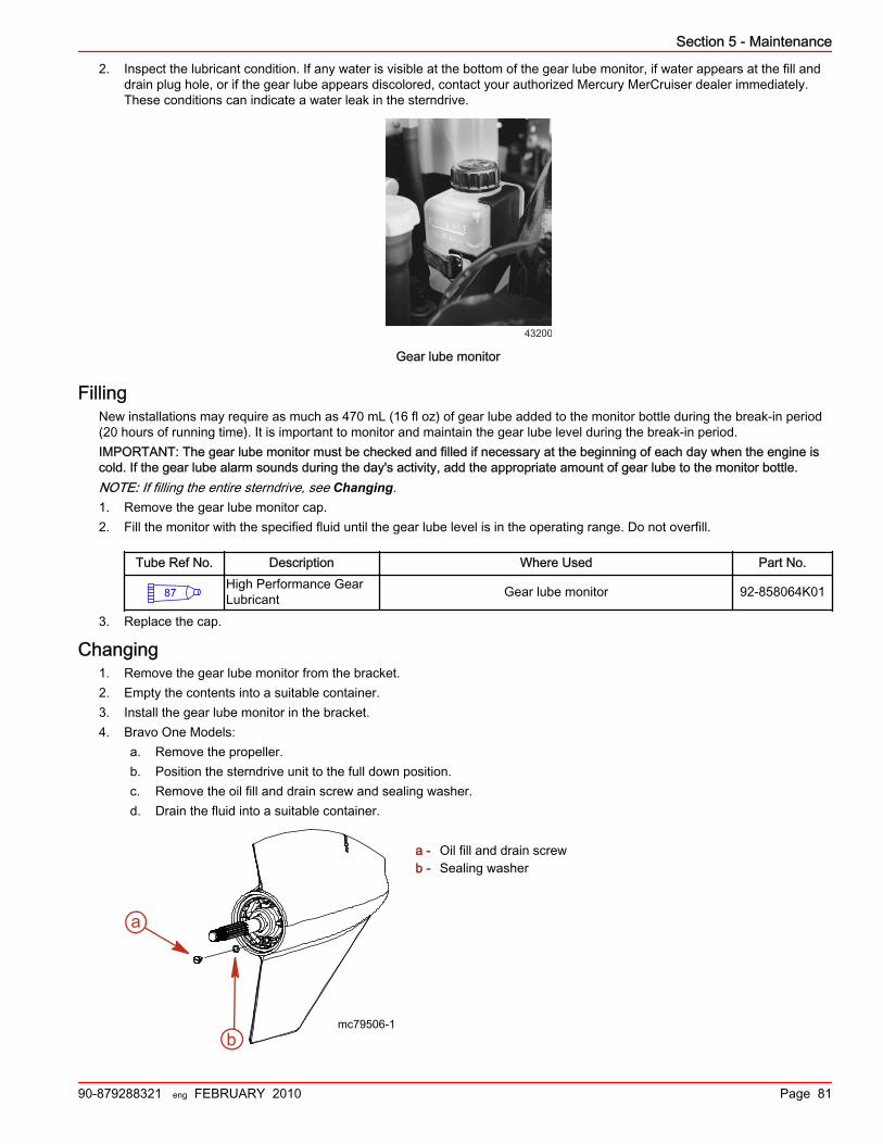
Section 5 - Maintenance
90-879288321 eng FEBRUARY 2010 Page 81
2. Inspect the lubricant condition. If any water is visible at the bottom of the gear lube monitor, if water appears at the fill anddrain plug hole, or if the gear lube appears discolored, contact your authorized Mercury MerCruiser dealer immediately.These conditions can indicate a water leak in the sterndrive.
43200
Gear lube monitor
FillingNew installations may require as much as 470 mL (16 fl oz) of gear lube added to the monitor bottle during the break‑in period(20 hours of running time). It is important to monitor and maintain the gear lube level during the break‑in period.IMPORTANT: The gear lube monitor must be checked and filled if necessary at the beginning of each day when the engine iscold. If the gear lube alarm sounds during the day's activity, add the appropriate amount of gear lube to the monitor bottle.NOTE: If filling the entire sterndrive, see Changing.1. Remove the gear lube monitor cap.2. Fill the monitor with the specified fluid until the gear lube level is in the operating range. Do not overfill.
Tube Ref No. Description Where Used Part No.
87High Performance GearLubricant Gear lube monitor 92-858064K01
3. Replace the cap.
Changing1. Remove the gear lube monitor from the bracket.2. Empty the contents into a suitable container.3. Install the gear lube monitor in the bracket.4. Bravo One Models:
a. Remove the propeller.b. Position the sterndrive unit to the full down position.c. Remove the oil fill and drain screw and sealing washer.d. Drain the fluid into a suitable container.
a - Oil fill and drain screwb - Sealing washer
a
mc79506-1b

Section 5 - Maintenance
Page 82 90-879288321 eng FEBRUARY 2010
5. All Other Models:a. Place the sterndrive unit in full trim out position.b. Remove the oil fill and drain screw and sealing washer.c. Drain the fluid into a suitable container.
a - Oil fill and drain screwb - Sealing washer
6. Remove the oil vent screw and sealing washer. Allow the oil to drain completely.
a - Oil vent screwb - Sealing washer
IMPORTANT: If any water drains from the unit, or if the fluid appears milky, the sterndrive unit is leaking. See yourauthorized Mercury MerCruiser dealer.
7. Lower the sterndrive unit so the propeller shaft is level.IMPORTANT: Use only Mercury/Quicksilver High Performance Gear Lubricant in sterndrive unit.
8. Fill the sterndrive unit through the oil fill and drain hole with specified gear lubricant until an air‑free stream of lubricantflows from oil vent hole.
Tube Ref No. Description Where Used Part No.
87High Performance GearLubricant Sterndrive unit 92-858064K01
9. Install the oil vent screw and sealing washer.10. Continue to pump gear lubricant into the drive through the oil fill and drain hole until gear lubricant appears in the gear lube
monitor.11. Fill the monitor so that the oil level is in the operating range. Do not overfill.12. Ensure that the rubber gasket is inside the cap and install. Do not overtighten.
NOTE: Oil capacities include the gear lube monitor.
Model Capacity Fluid Type
Bravo One 2736 ml (92‑1/2 oz.)
High Performance Gear LubricantBravo Two 3209 ml (108‑1/2 oz.)
Bravo Three (Single seawater pickup) 2972 ml (100‑1/2 oz.)
Bravo Three (Dual seawater pickup) 2736 ml (92‑1/2 oz.)
13. Remove the pump from the oil fill and drain hole. Quickly install the sealing washer and screw. Tighten securely.14. Reinstall the propeller. Refer to Propellers.15. Check the oil level after the first use.
b
amc79507-1
mc77106-1
ba

Section 5 - Maintenance
90-879288321 eng FEBRUARY 2010 Page 83
IMPORTANT: Oil level in the gear lube monitor rises and falls during operation. Always check the oil level when the sterndriveis cool and the engine is off.
Power Trim FluidChecking
IMPORTANT: Check the oil level with the sterndrive unit in the full down/in position only.1. Place the sterndrive unit in full down/in position.2. Observe the oil level. Level must be between the "MIN" and "MAX" lines on the reservoir.
a - Reservoirb - "MIN" and "MAX" lines
3. Fill as necessary with the specified fluid.
Tube Ref No. Description Where Used Part No.
114Power Trim and SteeringFluid Power trim pump 92-858074K01
Filling1. Remove the fill cap from the reservoir.
NOTE: Fill cap is vented.2. Add lubricant to bring level to the within the "MIN" and "MAX" lines on the reservoir.
Tube Ref No. Description Where Used Part No.
114Power Trim and SteeringFluid Power trim pump 92-858074K01
3. Install the cap.
ChangingPower trim fluid does not require changing unless it becomes contaminated with water or debris. Contact your authorizedMercury MerCruiser dealer.
BatteryRefer to specific instructions and warnings accompanying your battery. If this information is not available, observe the followingprecautions when handling a battery.
! WARNINGRecharging a weak battery in the boat, or using jumper cables and a booster battery to start the engine, can cause seriousinjury or product damage from fire or explosion. Remove the battery from the boat and recharge in a ventilated area awayfrom sparks or flames.
a b7876

Section 5 - Maintenance
Page 84 90-879288321 eng FEBRUARY 2010
! WARNINGAn operating or charging battery produces gas that can ignite and explode, spraying out sulfuric acid, which can causesevere burns. Ventilate the area around the battery and wear protective equipment when handling or servicing batteries.
Multiple EFI Engine Battery PrecautionsAlternators: Alternators are designed to charge the battery that supplies electrical power to the engine that the alternator ismounted on. When batteries for two different engines are connected, one alternator will supply all of the charging current forboth batteries. Normally, the other engine's alternator will not be required to supply any charging current.EFI electronic control module (ECM): The ECM requires a stable voltage source. During multiple engine operation, anonboard electrical device may cause a sudden drain of voltage at the engine's battery. The voltage may go below the ECM'sminimum required voltage. Also, the alternator on the other engine may now start charging. This could cause a voltage spike inthe engine's electrical system.In either case, the ECM could shut off. When the voltage returns to the range that the ECM requires, the ECM will reset itself,and the engine will operate normally. The ECM shuts off and resets itself so quickly that the engine may only seem to have anignition miss.Batteries: Boats with multiengine EFI power packages require each engine be connected to its own battery. This ensures thatthe engine's ECM has a stable voltage source.Battery switches: Battery switches should always be positioned so each engine is operating off of its own battery. Do notoperate engines with switches in both or all position. In an emergency, another engine's battery can be used to start an enginewith a dead battery.Battery isolators: Isolators can be used to charge an auxiliary battery used for powering accessories in the boat. They shouldnot be used to charge the battery of another engine in the boat unless the type of isolator is specifically designed for thispurpose.Generators: The generator's battery should be considered another engine's battery.
Cleaning the Flame Arrestor! WARNING
Fuel is flammable and explosive. Ensure that the key switch is off and the lanyard is positioned so that the engine cannotstart. Do not smoke or allow sources of spark or open flame in the area while servicing. Keep the work area well ventilatedand avoid prolonged exposure to vapors. Always check for leaks before attempting to start the engine, and wipe up anyspilled fuel immediately.
1. Remove the engine cover.2. Loosen the flame arrestor clamp and remove the flame arrestor.

Section 5 - Maintenance
90-879288321 eng FEBRUARY 2010 Page 85
3. Clean the flame arrestor with solvent. Dry with compressed air or allow to air dry completely.
a - Flame arrestor
4. Install flame arrestor. Tighten the flame arrestor clamp.5. Install the engine cover.
Water‑Separating Fuel Filter! WARNING
Fuel is flammable and explosive. Ensure that the key switch is off and the lanyard is positioned so that the engine cannotstart. Do not smoke or allow sources of spark or open flame in the area while servicing. Keep the work area well ventilatedand avoid prolonged exposure to vapors. Always check for leaks before attempting to start the engine, and wipe up anyspilled fuel immediately.
! CAUTIONFailure to release pressure from the fuel system will result in fuel spraying out, which can cause a fire or explosion. Allow theengine to cool completely and release all fuel pressure before servicing any part of the fuel system. Always protect eyes andskin from pressurized fuel and vapors.
8482
a

Section 5 - Maintenance
Page 86 90-879288321 eng FEBRUARY 2010
GEN III Models
a - Cool Fuel Moduleb - Cool Fuel Module harnessc - Filter capd - Filter assembly retaining screwe - Fuel filter elementf - Filter cupg - Cool Fuel Module filter reservoirh - O‑ring
Removal1. Allow the engine to cool down.
NOTE: Mercury MerCruiser recommends that the engine be shut off for 12 hours prior to filter removal.2. Close fuel supply valve, if equipped.3. Disconnect the Cool Fuel Module harness from the engine wiring harness.4. Turn the key switch to the start position and allow the starter to operate for 5 seconds.5. Turn key switch to off position.6. Loosen each filter assembly retaining screw until the screw is disengaged from the Cool Fuel Module. Do not remove the
filter assembly retaining screws from the filter cap.7. Unseat the filter assembly by grasping the filter assembly handle and pulling upward. Do not remove the filter assembly
from the Cool Fuel Module at this time.8. Allow any fuel that may be in the filter assembly to drain out through the bottom of the filter assembly and into the Cool
Fuel Module filter reservoir.9. Remove the filter cup from the filter cap by grasping the filter cap and rotating it in a clockwise direction while holding the
filter cup stationary.10. Remove the used water‑separating fuel filter element from the filter cup, place it in a clean, approved container.11. Dispose of any water or debris that may be in the filter cup.
Installation1. Install a new water‑separating fuel filter element into the filter cup. Push the element into the cup until completely seated.2. Install new O‑ring on the filter cup.3. Attach the filter cap to the filter cup by grasping the filter cap and rotating it in a counter clockwise direction while holding
the filter cup stationary, until the filter cap locks securely into place.4. Install the fuel filter assembly slowly into the Cool Fuel Module to prevent spilling fuel, and align the screws retained in the
filter cap with the screw holes in the Cool Fuel Module. Tighten the filter assembly retaining screws until hand tight.5. Ensure that the filter cap is firmly seated against the Cool Fuel Module and torque each filter assembly retaining screw.
Description Nm lb. in. lb. ft.
Filter assembly retaining screw 6 53
d
a
b
c
e
f
g
h
8837
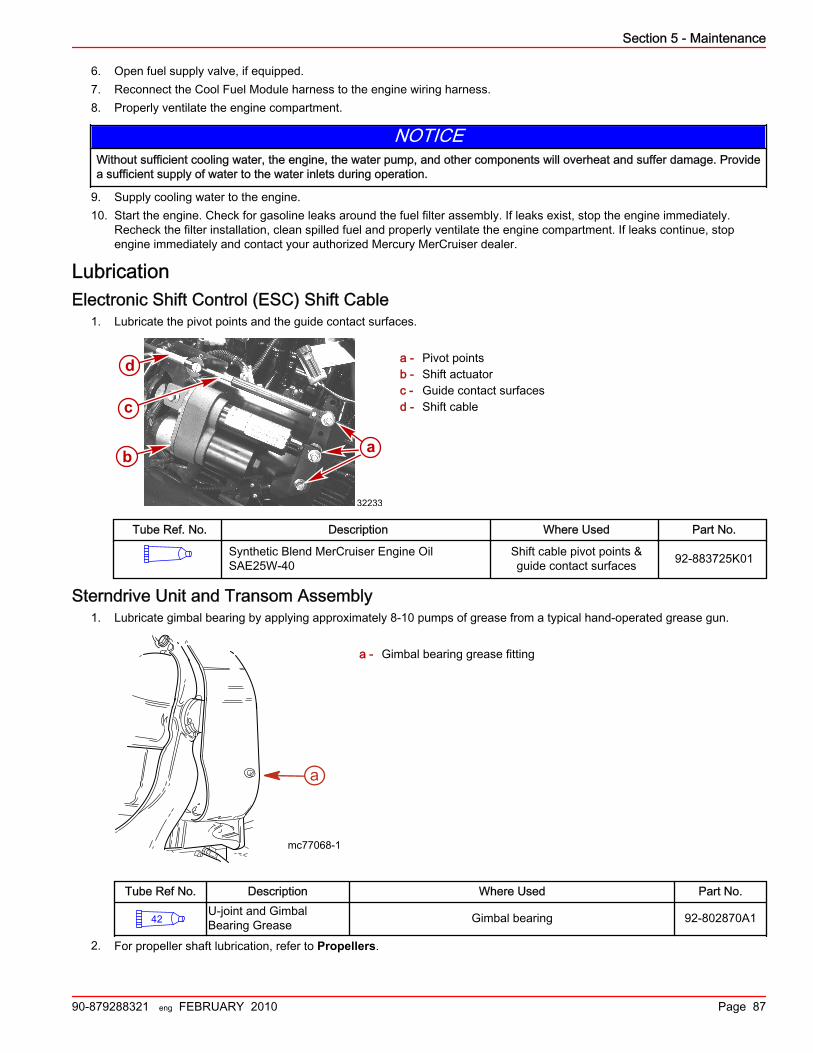
Section 5 - Maintenance
90-879288321 eng FEBRUARY 2010 Page 87
6. Open fuel supply valve, if equipped.7. Reconnect the Cool Fuel Module harness to the engine wiring harness.8. Properly ventilate the engine compartment.
NOTICEWithout sufficient cooling water, the engine, the water pump, and other components will overheat and suffer damage. Providea sufficient supply of water to the water inlets during operation.
9. Supply cooling water to the engine.10. Start the engine. Check for gasoline leaks around the fuel filter assembly. If leaks exist, stop the engine immediately.
Recheck the filter installation, clean spilled fuel and properly ventilate the engine compartment. If leaks continue, stopengine immediately and contact your authorized Mercury MerCruiser dealer.
LubricationElectronic Shift Control (ESC) Shift Cable
1. Lubricate the pivot points and the guide contact surfaces.
a - Pivot pointsb - Shift actuatorc - Guide contact surfacesd - Shift cable
Tube Ref. No. Description Where Used Part No.
Synthetic Blend MerCruiser Engine OilSAE25W‑40
Shift cable pivot points &guide contact surfaces 92‑883725K01
Sterndrive Unit and Transom Assembly1. Lubricate gimbal bearing by applying approximately 8‑10 pumps of grease from a typical hand‑operated grease gun.
a - Gimbal bearing grease fitting
Tube Ref No. Description Where Used Part No.
42U-joint and GimbalBearing Grease Gimbal bearing 92-802870A1
2. For propeller shaft lubrication, refer to Propellers.
32233
c
a
d
b
mc77068-1
a

Section 5 - Maintenance
Page 88 90-879288321 eng FEBRUARY 2010
Sterndrive U‑Joint Shaft Splines and O‑Rings (Sterndrive Unit Removed)1. Coat sterndrive U‑joint O‑rings and driveshaft splines with grease.
a - Driveshaft splinesb - U‑joint O‑rings (3)
Tube Ref No. Description Where Used Part No.
91Engine Coupler SplineGrease Driveshaft splines and U-joint O-rings 92-802869A 1
2. For propeller shaft lubrication, refer to Propellers.
Engine CouplerLubricate engine coupler splines through the grease fittings on the coupler by applying approximately 8–10 pumps of greasefrom a typical hand‑operated grease gun.NOTE: If the boat is operated at idle for prolonged periods of time, the coupler should be lubricated every 50 hours.
Bravo drive couplera - Grease fitting
Tube Ref No. Description Where Used Part No.
91Engine Coupler SplineGrease Coupler 92-802869A 1
NOTE: On Bravo models, the coupler and shaft splines can be lubricated without removing the sterndrive. Apply lubricant froma typical hand‑operated grease gun until a small amount of grease begins to push out.
PropellersPropeller Repair
Some damaged propellers can be repaired. Contact your authorized Mercury MerCruiser dealer.
b
a
8591
a a14535
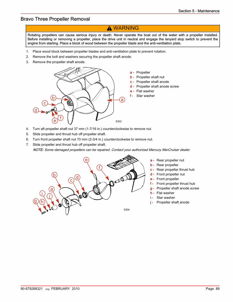
Section 5 - Maintenance
90-879288321 eng FEBRUARY 2010 Page 89
Bravo Three Propeller Removal
! WARNINGRotating propellers can cause serious injury or death. Never operate the boat out of the water with a propeller installed.Before installing or removing a propeller, place the drive unit in neutral and engage the lanyard stop switch to prevent theengine from starting. Place a block of wood between the propeller blade and the anti‑ventilation plate.
1. Place wood block between propeller blades and anti‑ventilation plate to prevent rotation.2. Remove the bolt and washers securing the propeller shaft anode.3. Remove the propeller shaft anode.
a - Propellerb - Propeller shaft nutc - Propeller shaft anoded - Propeller shaft anode screwe - Flat washerf - Star washer
4. Turn aft propeller shaft nut 37 mm (1‑7/16 in.) counterclockwise to remove nut.5. Slide propeller and thrust hub off propeller shaft.6. Turn front propeller shaft nut 70 mm (2‑3/4 in.) counterclockwise to remove nut.7. Slide propeller and thrust hub off propeller shaft.
NOTE: Some damaged propellers can be repaired. Contact your authorized Mercury MerCruiser dealer.
a - Rear propeller nutb - Rear propellerc - Rear propeller thrust hubd - Front propeller nute - Front propellerf - Front propeller thrust hubg - Propeller shaft anode screwh - Flat washeri - Star washerj - Propeller shaft anode
ab
dc
fe 5303
e
f
a
bc d
5304
g h
i j

Section 5 - Maintenance
Page 90 90-879288321 eng FEBRUARY 2010
Bravo Three Propeller Installation
NOTICEOperating the engine with a loose propeller can damage the propeller, the drive, or drive components. Always tighten thepropeller nut or nuts to specification and check for tightness periodically and at the required maintenance interval.
a - Rear propeller nutb - Rear propellerc - Rear propeller thrust hubd - Front propeller nute - Front propellerf - Front propeller thrust hubg - Propeller shaft anode screwh - Flat washeri - Star washerj - Propeller shaft anode
1. Slide forward thrust hub onto propeller shaft with tapered side toward propeller hub (toward end of shaft).2. Apply a liberal coat of one of the following lubricants to the propeller shaft.
Tube Ref No. Description Where Used Part No.
34 Special Lubricant 101 Propeller shaft 92-802865Q02
94 Anti-Corrosion Grease Propeller shaft 92-802867Q 1
952-4-C Marine Lubricantwith PTFE Propeller shaft 92-802859A 1
3. Align splines and place propeller on propeller shaft.4. Install and torque the propeller nut. Check propeller at least every 20 hours of operation and retorque as needed.
Description Nm lb‑in. lb‑ft
Forward propeller nut 136 – 100
5. Slide aft thrust hub onto propeller shaft, with tapered side toward propeller hub (toward end of shaft).6. Align splines and place propeller on propeller shaft.7. Install and torque the propeller nut. Check propeller at least every 20 hours of operation and retorque as needed.
Description Nm lb‑in. lb‑ft
Aft propeller nut 81 – 60
8. Install the propeller shaft anode over the propeller shaft nut.9. Place the flat washer onto the propeller shaft anode screw.10. Place the star washer onto the propeller shaft anode screw.
e
f
a
bc d
5304
g h
i j

Section 5 - Maintenance
90-879288321 eng FEBRUARY 2010 Page 91
11. If a propeller shaft anode is reinstalled, apply Loctite Threadlocker 271 to the threads of the propeller shaft anode screw.
a - Propellerb - Propeller shaft nutc - Propeller shaft anoded - Propeller shaft anode screwe - Flat washerf - Star washer
Tube Ref No. Description Where Used Part No.
7 Loctite 271 Threadlocker Propeller shaft threads 92-809819
12. Secure the propeller shaft anode to the propeller shaft using the propeller shaft anode screw and washers. Torque thescrew.
Description Nm llb‑in. lb‑ft
Propeller shaft anode screw 38 mm (0.3125‑18 x 1.5 in.) long 27 – 20
Serpentine Drive Belt! WARNING
Inspecting the belts with the engine running may cause serious injury or death. Turn off the engine and remove the ignitionkey before adjusting tension or inspecting belts.
Belt Routing Diagrama - Idler pulleyb - Water circulating pump pulleyc - Alternator pulleyd - Idler pulleye - Power steering pump pulleyf - Idler pulleyg - Crankshaft pulleyh - Seawater pump pulleyi - Tensioner pulley
Checking1. Inspect the drive belt for proper tension and for the following:
• Excessive wear• Cracks
NOTE: Minor, transverse cracks (across the belt width) may be acceptable. Longitudinal cracks (in the direction ofbelt length) that join transverse cracks are NOT acceptable.
• Fraying• Glazed surfaces
ab
dc
fe 5303
b c
d
e
fg
h
i
a
33539

Section 5 - Maintenance
Page 92 90-879288321 eng FEBRUARY 2010
• Proper tension ‑ 13 mm (1/2 in.) deflection, with moderate thumb pressure, on the belt at the location that has thelongest distance between two pulleys.
mc75130-1
ReplacingIMPORTANT: If a belt is to be reused, it should be installed in the same direction of rotation as before.The belt tensioner is designed to operate within the limits of arm movement provided by the cast stops when the belt length andgeometry are correct.If the tensioner is contacting either of the limits during operation, check the mounting brackets and the belt length. Loosebrackets, bracket failure, accessory drive component movement, incorrect belt length, or belt failure can cause the tensioner tocontact the limits.See your authorized MerCruiser dealer for service if these conditions exist.
! CAUTIONRapid release of the belt tensioner, or allowing the tensioner to snap back quickly, could cause injury or product damage.Relieve the spring tension slowly.
1. Use a breaker bar and appropriate socket to hold back the tensioner and relieve the belt tension. Rotate the tensioneraway from belt until it stops. Remove the belt from the idler pulley and slowly relieve the tension on the breaker bar.
Breaker bar with arrow in direction ofmovement to relieve tension
a - Breaker bar
2. Remove the belt and reroute the replacement belt according to the belt routing diagram.
8115
a

Section 5 - Maintenance
90-879288321 eng FEBRUARY 2010 Page 93
3. Use a breaker bar and appropriate socket to position the tensioner back to the engine running location and slide the beltover the tensioner pulley. Slowly relieve the tensioner to the belt.
Breaker bar with arrow in direction ofmovement to install belt
a - Breaker bar
Corrosion ProtectionCorrosion Information
Whenever two or more dissimilar metals are submerged in a conductive solution, such as saltwater, polluted water or waterwith a high mineral content, a chemical reaction takes place causing electrical current to flow between metals. The electricalcurrent flow causes the metal that is most chemically active, or anodic, to erode. This is known as galvanic corrosion. For moreinformation contact your authorized Mercury MerCruiser dealer and refer to the Mercury Precision Parts / Marine CorrosionProtection Guide (90‑881813003).
Maintaining Ground Circuit ContinuityThe transom assembly and sterndrive are equipped with a ground wire circuit to ensure good electrical continuity between theengine, transom assembly, and sterndrive components. Good continuity is essential for the MerCathode System to functioneffectively.
MerCathode System Battery RequirementsThe Mercury MerCruiser MerCathode system requires a minimum battery charge of 12.6 volts at all times to maintainfunctionality.Boats equipped with a MerCathode system that use shore power, and are not run for a long period of time, must use a batterycharger to maintain a minimum battery charge of 12.6 volts or above.Boats equipped with a MerCathode system that do not have access to shore power must be operated often enough to maintaina minimum battery charge of 12.6 volts or above at all times.
Anodes and MerCathode System LocationsIMPORTANT: Replace sacrificial anodes if eroded 50 percent or more.The following sacrificial anodes are installed at different locations on your power package. These anodes help protect againstgalvanic corrosion by sacrificing their metal to be slowly eroded instead of the metal components on the power package.MerCathode System—Electrode assembly replaces the anode block. System should be tested to ensure adequate output.The test should be performed where boat is moored, using Quicksilver Reference Electrode and Test Meter.
8115
a

Section 5 - Maintenance
Page 94 90-879288321 eng FEBRUARY 2010
Description Location Figure
Gearcase anode plate Mounted on the underside of thelower gearcase.
20336
Ventilation plate anode Mounted on the front of the gearcase.
20338
MerCathode System
The MerCathode electrode ismounted to the underside of thegimbal housing. The MerCathodecontroller is mounted on the engineor on the boat transom. The controllerharness connects to the electrodeharness.
20340
Anode kit (if equipped) Mounted to the boat transom.
20341
Trim cylinder anodes Mounted on each of the trimcylinders.
20342
Bearing carrier anode (Bravo One)Located in front of the propeller,between the front side of thepropeller and the gear housing.
20343
Propshaft anode (Bravo Three) Located behind the aft propeller.
20344
Checking the Quicksilver MerCathode SystemThe MerCathode system should be tested to ensure adequate output. Perform the test where boat is moored, using thereference electrode and test meter. Contact your authorized Mercury MerCruiser dealer for service and information .

Section 5 - Maintenance
90-879288321 eng FEBRUARY 2010 Page 95
Reference Electrode 91‑76675T 1
9188
Senses and electrical current in the water when testing the MerCathode system.Use to check hull potential.
Power Package Exterior Surfaces1. Spray the entire power package at recommended intervals with Corrosion Guard. Follow the instructions on the can for
proper application.
Tube Ref No. Description Where Used Part No.
120 Corrosion Guard Painted surfaces 92-802878 55
2. Clean the entire power package. External surfaces that have become bare should be repainted with the recommendedprimer and spray paint at recommended intervals.
Description Part Number
Mercury Light Gray PrimerPainted surfaces
92‑802878 52
Mercury Phantom Black 92‑802878Q 1
Boat Bottom CareTo achieve maximum performance and fuel economy, the boat bottom must be kept clean. Accumulation of marine growth orother foreign matter can greatly reduce boat speed and increase fuel consumption. To ensure best performance and efficiency,periodically clean the boat bottom in accordance with manufacturer's recommendations.In some areas, it may be advisable to paint the bottom to help prevent marine growth. Refer to the following information forspecial notes about the use of antifouling paints.
Antifouling PaintIMPORTANT: Corrosion damage that results from the improper application of antifouling paint will not be covered by the limitedwarranty.You may apply antifouling paint to the boat hull and boat transom but you must observe the following precautions:IMPORTANT: Do not paint or pressure‑wash the anodes or the MerCathode system reference electrode and anode. Doing sowill render them ineffective as inhibitors of galvanic corrosion.

Section 5 - Maintenance
Page 96 90-879288321 eng FEBRUARY 2010
IMPORTANT: If antifouling protection is required for the boat hull or boat transom, you can use copper‑based paint if it is notprohibited by law. If you are using copper based antifouling paint, observe the following precaution:• Avoid an electrical interconnection between the Mercury MerCruiser product, anodic blocks, or MerCathode system and
the paint by allowing a minimum of 40 mm (1‑1/2 in.) unpainted area on transom of the boat around these items.
a - Painted boat transomb - Minimum 40 mm (1‑1/2 in.) unpainted area around
transom assembly
NOTE: Sterndrive and transom assembly can be painted with a good marine paint or an antifouling paint that does notcontain copper or any other material that could conduct electrical current. Do not paint drain holes, anodes, theMerCathode system or items specified by the boat manufacturer.
NOTICEWashing the MerCathode assembly can damage components and lead to rapid corrosion. Do not use any cleaningequipment such as brushes or high‑pressure washers to clean the MerCathode assembly.
Do not power‑wash a sterndrive that has a MerCathode assembly. Doing so can damage the coating on the reference wire ofthe MerCathode assembly and increase corrosion.
a - Reference electrodeb - Anode plate
8107
b
a
21563
b
a

Section 5 - Maintenance
90-879288321 eng FEBRUARY 2010 Page 97
Sterndrive Surface Care
Standard Bravo sterndrivea - Sacrificial trim cylinder anodeb - Sacrificial anodic platec - Steering lever ground wired - Ground wire between the gimbal ring and bell housinge - Stainless steel hosesf - Ground wire between the gimbal housing and trim cylinderg - Ground wire between the gimbal ring and gimbal housing
We recommend the following maintenance items to help keep your sterndrive corrosion‑free:• Maintain a complete paint covering on the sterndrive.• Check the finish regularly. Prime and paint nicks and scratches using Mercury enamel paint and touch up paint. Use only
tin‑based antifouling paint or its equivalent on or near aluminum surfaces below the waterline.• If bare metal is showing, apply two coats of paint.
Description Where used Part number
Mercury Phantom Black Bare metal 92‑ 802878‑1
• Spray all electrical connections with sealant.
Tube Ref No. Description Where Used Part No.
25 Liquid Neoprene All electrical connections 92- 25711 3
• Inspect the sacrificial trim tab or anode plate if equipped, at regular intervals and replace it before it is half gone. If astainless steel propeller is installed, additional anodes or a MerCathode system will be required.
• Inspect the propeller shaft for fishing line, which can cause corrosion on a stainless steel shaft.• Remove the propeller at least every 60 days and lubricate the propeller shaft.• Do not use lubricants containing graphite on or near the aluminum in saltwater.• Do not paint trim tabs or the mounting surface.
Flushing the Seawater System—Sterndrive ModelsGeneral Information—Bravo Sterndrive
Your boat could be equipped with a combination of any of three different types of water pickups: through‑hull, through‑transom,and through‑sterndrive. The flushing procedures for these systems are separated into two categories: sterndrive water pickupsand alternative water pickups.
21083
a
b
c
d
e
fg

Section 5 - Maintenance
Page 98 90-879288321 eng FEBRUARY 2010
Flushing Attachments
Flushing Device 91‑44357Q 2
9192
Attaches to the water intakes; provides a fresh water connection when flushingthe cooling system or operating the engine.
Dual Water Pickup Flush Gearcase Seal Kit 91‑881150K 1
9194
Blocks off the front water inlet holes on the dual water inlet gearcases.
Flushing Kit 91‑849996T 1
9195
Use for flushing gearcases with low water inlets.
Sterndrive Water PickupsThere are three types of water pickups available on Mercury MerCruiser sterndrives: low water, dual water, and side pickups.Dual water pickups require the flushing attachment (44357Q 2) and the flush seal kit (881150K 1), low water pickups requirethe flushing attachment (849996T 1), and side pickups require the flushing attachment (44357Q 2).
5752 57715773
Dual water pickup Low water pickup Side pickup
Boat Out of the Water—Bravo SterndriveIMPORTANT: Flushing the power package is most effective when performed with the boat and sterndrive out of the water.IMPORTANT: Flushing is needed if the engine package has been operated in saltwater, brackish water, mineral‑laden water, orpolluted water. For best results, flushing is recommended after each outing and before cold weather and extended storage.1. Lower the sterndrive to full down/in position.

Section 5 - Maintenance
90-879288321 eng FEBRUARY 2010 Page 99
! WARNINGRotating propellers can cause serious injury or death. Never operate the boat out of the water with a propeller installed.Before installing or removing a propeller, place the drive unit in neutral and engage the lanyard stop switch to prevent theengine from starting. Place a block of wood between the propeller blade and the anti‑ventilation plate.
2. Remove the propeller. Refer to the appropriate Mercury MerCruiser sterndrive service manual.3. Install the appropriate flushing attachment over the water inlet holes in the gear housing.4. Connect the water supply hose to the water source.
NOTICEFlushing the engine when it is not operating will result in water collecting in the exhaust system, damaging the engine. Do notsupply flush water for more than 15 seconds without the engine operating.
5. With the sterndrive in the normal operating position, completely open the water source to provide maximum water supply.6. Place the remote control in the neutral idle speed position.7. Immediately start the engine.
NOTICEOperating the engine out of the water at high speeds creates suction, which can collapse the water supply hose and overheatthe engine. Do not operate the engine above 1400 RPM out of the water and without sufficient cooling water supply.
8. Press the throttle‑only button and slowly advance the throttle until the engine reaches 1300 RPM (± 100 RPM).9. Observe the water temperature gauge to ensure that the engine is operating in the normal range.10. Operate the engine with the sterndrive in neutral for a minimum of 10 minutes.11. For power packages operated in saltwater, brackish water, mineral‑laden water, or polluted water, continue to operate the
engine until the discharge water is clear.12. Slowly return the throttle to idle speed position.13. Stop the engine.14. Immediately shut off the supply water and remove the flushing attachment.15. Install the propeller. Refer to the appropriate Mercury MerCruiser sterndrive service manual.
Boat in the Water—Bravo SterndriveIMPORTANT: Flushing the power package is most effective when performed with the boat and sterndrive out of the water.IMPORTANT: Flushing is needed if the engine package has been operated in saltwater, brackish water, mineral‑laden water, orpolluted water. For best results, flushing is recommended after each outing and before cold weather and extended storage.1. Raise the sterndrive to the trailer position.2. Install the appropriate flushing attachment over the water inlet holes in the gear housing.3. Lower the sterndrive to the full down/in position.4. Connect the water supply hose to the water source.
NOTICEFlushing the engine when it is not operating will result in water collecting in the exhaust system, damaging the engine. Do notsupply flush water for more than 15 seconds without the engine operating.
5. With the sterndrive in the normal operating position, completely open the water source to provide maximum water supply.6. Place the remote control in the neutral idle speed position.7. Immediately start the engine.8. Press the throttle‑only button and slowly advance the throttle until the engine reaches 1300 RPM (± 100 RPM).9. Observe the water temperature gauge to ensure that the engine is operating in the normal range.10. Operate the engine with the sterndrive in neutral for a minimum of 10 minutes.11. For engine packages operated in saltwater, brackish water, mineral‑laden water, or polluted water, continue to operate the
engine until the discharge water is clear.12. Slowly return the throttle to the idle speed position.13. Stop the engine.14. Immediately shut off the supply water. Do not remove the flushing attachment from the sterndrive at this time.

Section 5 - Maintenance
Page 100 90-879288321 eng FEBRUARY 2010
NOTICEDisconnecting the seawater inlet hose will cause water to enter the bilge resulting in engine damage. Close the seacockbefore disconnecting the seawater inlet hose. Plug the seawater inlet hose immediately after disconnecting it.
15. Close the seacock, if equipped, then disconnect the seawater inlet hose to prevent water from siphoning into the engine orboat.
16. If not equipped with a seacock, disconnect the seawater inlet hose from the seawater pump, and immediately plug thehose to prevent water from siphoning into the engine or boat.
17. Raise the sterndrive to the trailer position.18. Remove the flushing attachment from the sterndrive.19. Tag the ignition switch with an appropriate tag requiring the seacock to be opened or the seawater inlet hose to be
reconnected before operating the engine.
Boat Out of the Water—Alternative Water PickupsIMPORTANT: Flushing the power package is most effective when performed with the boat and sterndrive out of the water.IMPORTANT: Flushing is needed If the engine package has been operated in saltwater, brackish water, mineral‑laden water,or polluted water. For best results flushing is recommended after each outing and before cold weather and extended storage.1. Lower the sterndrive to the full down/in position.
! WARNINGRotating propellers can cause serious injury or death. Never operate the boat out of the water with a propeller installed.Before installing or removing a propeller, place the drive unit in neutral and engage the lanyard stop switch to prevent theengine from starting. Place a block of wood between the propeller blade and the anti‑ventilation plate.
2. Remove the propeller. Refer to the appropriate Mercury MerCruiser sterndrive service manual.3. Close the seacock, if equipped.4. If not equipped with a seacock, disconnect the seawater inlet hose from the seawater pump.5. Using a suitable adapter, connect the flushing hose from the water source to the water inlet of the seawater pump.
NOTICEFlushing the engine when it is not operating will result in water collecting in the exhaust system, damaging the engine. Do notsupply flush water for more than 15 seconds without the engine operating.
6. With the sterndrive in the normal operating position, completely open the water source to provide maximum water supply.7. Place the remote control in the neutral idle speed position.8. Immediately start the engine.
NOTICEOperating the engine out of the water at high speeds creates suction, which can collapse the water supply hose and overheatthe engine. Do not operate the engine above 1400 RPM out of the water and without sufficient cooling water supply.
9. Press the throttle‑only button and slowly advance the throttle until the engine reaches 1300 RPM (± 100 RPM).10. Observe the water temperature gauge to ensure that the engine is operating in the normal range.11. Operate the engine with the sterndrive in neutral for a minimum of 10 minutes.12. For engine packages operated in saltwater, brackish water, mineral‑laden water, or polluted water, continue to operate the
engine until the discharge water is clear.13. Slowly return the throttle to the idle speed position.14. Stop the engine.15. Immediately shut off the supply water and remove the flushing attachment.16. Install the water inlet hose to the seawater inlet of the seawater pump. Tighten the hose clamp securely.17. Install the propeller. Refer to the appropriate Mercury MerCruiser sterndrive service manual.
Boat in the Water—Alternative Water PickupsIMPORTANT: Flushing the power package is most effective when performed with the boat and sterndrive out of the water.IMPORTANT: Flushing is needed if the engine package has been operated in saltwater, brackish water, mineral‑laden water, orpolluted water. For best results flushing is recommended after each outing and before cold weather and extended storage.1. Lower the sterndrive to the full down/in position.

Section 5 - Maintenance
90-879288321 eng FEBRUARY 2010 Page 101
NOTICEDisconnecting the seawater inlet hose will cause water to enter the bilge resulting in engine damage. Close the seacockbefore disconnecting the seawater inlet hose. Plug the seawater inlet hose immediately after disconnecting it.
2. Close the seacock, if equipped, then disconnect the seawater inlet hose to prevent water from siphoning into the engine orboat.
3. If not equipped with a seacock, disconnect the seawater inlet hose from the seawater pump and immediately plug the hoseto prevent water from siphoning into the engine or boat.
4. Using a suitable adapter, connect the flushing hose from the water source to the water inlet of the seawater pump.
NOTICEFlushing the engine when it is not operating will result in water collecting in the exhaust system, damaging the engine. Do notsupply flush water for more than 15 seconds without the engine operating.
5. With the sterndrive in the normal operating position, completely open the water source to provide maximum water supply.6. Place the remote control in the neutral idle speed position.7. Immediately start the engine.
NOTICEOperating the engine out of the water at high speeds creates suction, which can collapse the water supply hose and overheatthe engine. Do not operate the engine above 1400 RPM out of the water and without sufficient cooling water supply.
8. Press the throttle‑only button and slowly advance the throttle until the engine reaches 1300 RPM (± 100 RPM).9. Observe the water temperature gauge to ensure that the engine is operating in the normal range.10. Operate the engine with the sterndrive in neutral for a minimum of 10 minutes.11. For engine packages operated in saltwater, brackish water, mineral‑laden water, or polluted water, continue to operate the
engine until the discharge water is clear.12. Slowly return the throttle to the idle speed position.13. Stop the engine.14. Immediately shut off the supply water and remove the flushing attachment.15. Tag the ignition switch with an appropriate tag requiring the seacock to be opened or the seawater inlet hose to be
reconnected before operating the engine.
SeaCore Power Package Flushing ProcedureNOTE: Flushing is needed only for salt, brackish, mineral laden or polluted water applications. Flushing is recommended aftereach outing for best results.IMPORTANT: Flushing the SeaCore power package with the boat and sterndrive in the water is less effective. Flushing theSeaCore power package is most effective when performed with the boat and sterndrive out of the water, such as on a boat liftor trailer.
Models Using The Sterndrive Water PickupIMPORTANT: The system is designed to flush the Bravo sterndrive and the engine with one water source. Do not block orremove the inlet water hose from the sterndrive to the engine.NOTE: Engines with the sterndrive water inlet blocked off at the gimbal housing: Refer to Alternative Water Pickups.
! WARNINGRotating propellers can cause serious injury or death. Never operate the boat out of the water with a propeller installed.Before installing or removing a propeller, place the drive unit in neutral and engage the lanyard stop switch to prevent theengine from starting. Place a block of wood between the propeller blade and the anti‑ventilation plate.
IMPORTANT: Do not allow the engine to pull air or seawater from alternative water pickup sources during the flushingprocedure. If equipped, ensure that all alternative water inlet hoses are plugged at both ends.1. Remove the boat from the water.

Section 5 - Maintenance
Page 102 90-879288321 eng FEBRUARY 2010
2. Close the seacock, if equipped.
For visual clarity, the secock shown is not installeda - Hose fitting to engineb - Seacockc - Handle (closed position)d - To water source pickup attachment
3. If equipped with an alternative water pickup and not equipped with a seacock, disconnect the water hose from thealternative water pickup and plug both ends, excluding the Bravo sterndrive.
4. Ensure that the inlet water hose from the sterndrive to the engine is connected.5. Remove the quick‑connect fitting from the parts bag supplied with the engine.6. Attach the quick‑connect fitting to a water hose.
a - Quick connect fitting (water hose end)b - Water hose
7. Snap the quick‑connect fitting with the water hose into the flush socket on the engine.
a - Water hoseb - Quick‑connect fitting (water hose end)c - Flush socket
8. Open the water source of the water hose to a full flow.9. Allow the water to flush the sterndrive for 30 seconds.10. Place the remote control in neutral idle speed position and start engine.
NOTICEWithout sufficient cooling water, the engine, the water pump, and other components will overheat and suffer damage. Providea sufficient supply of water to the water inlets during operation.
11. Operate the engine at idle speed in neutral gear. Do not exceed 1200 RPM.12. Monitor the engine temperature while operating the engine.
a
c
b d
18510
18487
a b
a
b
c
18489

Section 5 - Maintenance
90-879288321 eng FEBRUARY 2010 Page 103
13. Flush the engine for 5 to 10 minutes or until discharge water is clear.14. Shut off the engine.15. Allow the water to flush the sterndrive for 10 seconds.16. Turn off the water source.17. Disconnect the quick‑connect fitting and water hose from the flush socket on the engine by pressing the release button on
the flush socket.
a - Quick‑connect fitting (water hose end)b - Flush socket release button
18. Remove the quick‑connect fitting from the water hose.
a - Quick‑connect fitting (water hose end)b - Water hose
19. Retain the quick‑connect fitting with the water hose end for repeated use by storing it separately in a storage compartmenton the boat for easy access.IMPORTANT: Do not store the quick‑connect fitting in the flush socket on the engine. Doing so would allow the seawaterpump to suck air during engine operation causing an overheating problem. Damages due to engine overheating are notcovered by Mercury MerCruiser Warranty.
Quick-connect fitting stored in the boata - Quick‑connect fitting (water hose end)
b
a
18488
18487
a b
25900
a

Section 5 - Maintenance
Page 104 90-879288321 eng FEBRUARY 2010
20. Insert the dust cover in the flush socket on the engine.
Dust cover installed in the flush socketa - Dust coverb - Flush socket
IMPORTANT: If the unit is to be stored in the water, the seacock should remain closed until time of usage. If unit is to bestored out of the water, open the seacock.
21. Open the seacock, if equipped, or reconnect the alternative water inlet source prior to operating the engine.
a
b
18490

Section 6 - Storage
90-879288321 eng FEBRUARY 2010 Page 105
Section 6 - StorageTable of ContentsCold Weather or Extended Storage.................................... 106
Preparing Power Package for Storage........................ 106Engine and Fuel System Preparation .................. 106
Draining the Seawater System........................................... 107Drain System Identification.......................................... 107
Air Actuated Single Point Drain System .............. 107Manual Drain System .......................................... 108
Air Actuated Single Point Drain System...................... 108Boat in the Water ................................................. 108
Boat Out of the Water .......................................... 110Manual Drain System.................................................. 111
Boat in the Water ................................................. 111Boat out of the Water .......................................... 111
Draining the Sterndrive................................................ 112Draining Water from the Gen III Cool Fuel Module............ 113Battery Storage................................................................... 113Recommissioning the Power Package............................... 113
6

Section 6 - Storage
Page 106 90-879288321 eng FEBRUARY 2010
Cold Weather or Extended StorageIMPORTANT: Mercury MerCruiser strongly recommends that this service should be performed by an authorized MercuryMerCruiser dealer. Damage caused by freezing temperatures is not covered by the Mercury MerCruiser Limited Warranty.
NOTICEWater trapped in the seawater section of the cooling system can cause corrosion or freeze damage. Drain the seawatersection of the cooling system immediately after operation or before any length of storage in freezing temperatures. If the boatis in the water, keep the seacock closed until restarting the engine to prevent water from flowing back into the cooling system.If the boat is not fitted with a seacock, leave the water inlet hose disconnected and plugged.
NOTE: As a precautionary measure, attach a tag to the key switch or steering wheel of the boat reminding the operator to openthe seacock or unplug and reconnect the water inlet hose before starting the engine.IMPORTANT: Mercury MerCruiser requires that propylene glycol antifreeze, mixed to the manufacturers instructions, be usedin the seawater section of the cooling system for freezing temperatures or extended storage. Ensure that the propylene glycolantifreeze contains a rust inhibitor and is recommended for use in marine engines. Be certain to follow the propylene glycolmanufacturer's recommendations.
Preparing Power Package for Storage1. Fill the fuel tanks with fresh gasoline (that does not contain alcohol) and a sufficient amount of Quicksilver Gasoline
Stabilizer for Marine Engines to treat the gasoline. Follow instructions on the container.2. If the boat is to be placed in storage with fuel containing alcohol in fuel tanks (if fuel without alcohol is not available): Fuel
tanks should be drained as low as possible and Mercury/Quicksilver Gasoline Stabilizer for Marine Engines added to anyfuel remaining in the tank. Refer to Fuel Requirements for additional information.
3. Flush the cooling system. Refer to the Maintenance section.4. Supply cooling water to engine. Refer to the Maintenace section5. Operate the engine sufficiently to bring it up to normal operating temperature and allow fuel with Mercury/Quicksilver
Gasoline Stabilizer to circulate through the fuel system. Shut off the engine.6. Change the oil and oil filter.7. Prepare the engine and fuel system for storage. Refer to Engine and Fuel System Preparation.8. Drain the engine seawater cooling system. Refer to Draining the Seawater System.
NOTICEWater trapped in the seawater section of the cooling system can cause corrosion or freeze damage. Drain the seawatersection of the cooling system immediately after operation or before any length of storage in freezing temperatures. If the boatis in the water, keep the seacock closed until restarting the engine to prevent water from flowing back into the cooling system.If the boat is not fitted with a seacock, leave the water inlet hose disconnected and plugged.
9. For additional assurance against freezing and rust, after draining, fill the seawater cooling system with propylene glycolmixed to the manufacturer's recommendation to protect engine to the lowest temperature to which it will be exposed duringfreezing temperatures or extended storage.
10. Store the battery according to the manufacturer's instructions.
Engine and Fuel System Preparation
! WARNINGFuel is flammable and explosive. Ensure that the key switch is off and the lanyard is positioned so that the engine cannotstart. Do not smoke or allow sources of spark or open flame in the area while servicing. Keep the work area well ventilatedand avoid prolonged exposure to vapors. Always check for leaks before attempting to start the engine, and wipe up anyspilled fuel immediately.
! WARNINGFuel vapors trapped in the engine compartment may be an irritant, cause difficulty breathing, or may ignite resulting in a fireor explosion. Always ventilate the engine compartment before servicing the power package.
1. In a 23 liter (6 US gal) remote fuel tank mix:a. 19 liter (5 US gal) regular unleaded 87 octain (90 RON) gasolineb. 1.89 liter (2 US qt) Premium Plus 2‑Cycle TC‑W3 Outboard Oil

Section 6 - Storage
90-879288321 eng FEBRUARY 2010 Page 107
c. 150 ml (5 oz) Fuel System Treatment and Stabilizer or 30 ml (1 oz) Fuel System Treatment and StabilizerConcentrate
Tube Ref No. Description Where Used Part No.
115Premium Plus 2-cycle TC-W3 Outboard Oil Fuel system 92-858026K01
124Fuel System Treatment &Stabilizer Fuel system 92-8M0047932
2. Allow the engine to cool down.IMPORTANT: Immediately wipe up any fuel spills or sprays.
3. Close the fuel shut off valve, if equipped. Disconnect and plug the fuel inlet fitting if not equipped with a fuel shut off valve.4. Connect the remote fuel tank (with the fogging mixture) to the fuel inlet fitting.
IMPORTANT: Supply cooling water to the engine.5. Start and operate the engine at 1300 RPM for 5 minutes.6. After specified operating time is complete, slowly return throttle to idle RPM and shut engine off.
IMPORTANT: Ensure that some fogging mixture remains in the engine. Do not allow the engines fuel system to becomecompletely dry.
7. Replace the water separating fuel filter element. Refer to Section 5 for proper procedure.
Draining the Seawater System! CAUTION
Water can enter the bilge when the drain system is open, damaging the engine or causing the boat to sink. Remove the boatfrom the water or close the seacock, disconnect and plug the seawater inlet hose, and ensure the bilge pump is operationalbefore draining. Do not operate the engine with the drain system open.
IMPORTANT: Only drain the seawater section of the closed cooling system.IMPORTANT: The boat must be as level as possible to ensure complete draining of the cooling system.Your power package is equipped with a drain system. Refer to Drain System Identification to determine which instructionsapply to your power package.IMPORTANT: The engine must not be operating at any point during the draining procedure.
Drain System IdentificationAir Actuated Single Point Drain System
a - Actuator fittingb - Green indicatorsc - Manual release valve
b
c
a
8294
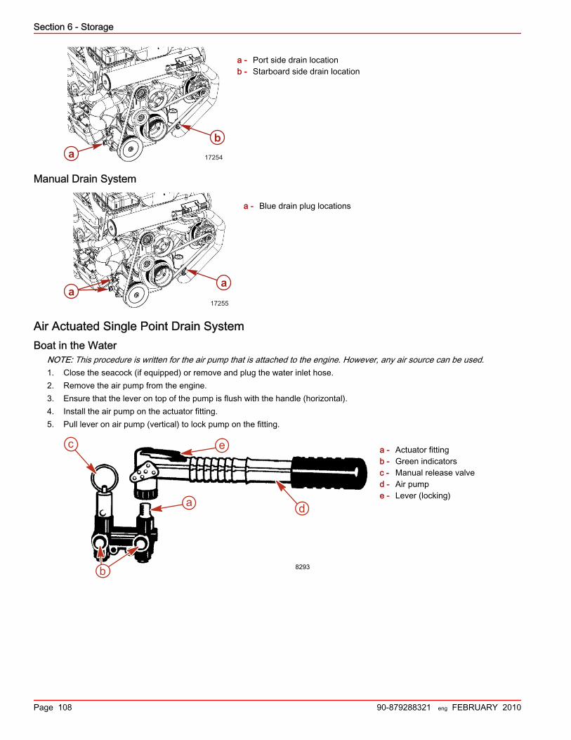
Section 6 - Storage
Page 108 90-879288321 eng FEBRUARY 2010
a - Port side drain locationb - Starboard side drain location
Manual Drain System
a - Blue drain plug locations
Air Actuated Single Point Drain SystemBoat in the Water
NOTE: This procedure is written for the air pump that is attached to the engine. However, any air source can be used.1. Close the seacock (if equipped) or remove and plug the water inlet hose.2. Remove the air pump from the engine.3. Ensure that the lever on top of the pump is flush with the handle (horizontal).4. Install the air pump on the actuator fitting.5. Pull lever on air pump (vertical) to lock pump on the fitting.
a - Actuator fittingb - Green indicatorsc - Manual release valved - Air pumpe - Lever (locking)
ab
17254
a17255
a
8293b
d
e
a
c

Section 6 - Storage
90-879288321 eng FEBRUARY 2010 Page 109
6. Pump air into the system until both green indicators extend and water drains from both sides of the engine. The port sidewill begin draining before the starboard side.
a - Actuator fittingb - Green indicatorsc - Manual release valve
7. Verify that water is draining from each opening. If not, use the Manual Drain System instructions.
a - Port side drain locationb - Starboard side drain location
8. Allow the system to drain for a minimum of five minutes. Pump air as necessary to keep the green indicators extended.9. For DTS engines, pull the lanyard stop switch (if equipped), or disable the ignition circuit by pulling the fuse marked "CD."10. Crank the engine over slightly with the starter motor to purge any water trapped in the seawater pump. Do not allow engine
to start.11. Remove the air pump from the air manifold and return it to the mounting bracket.12. Mercury MerCruiser recommends leaving the drain system open while transporting the boat or while performing other
maintenance. This helps ensure that all water is drained.13. Before launching the boat, pull up on the manual release valve. Verify that the green indicators are no longer extended.
a - Green indicators
14. Open the seacock, if equipped, or unplug and reconnect the water inlet hose prior to operating the engine.
b
c
a
8294
ab
17254
a6135

Section 6 - Storage
Page 110 90-879288321 eng FEBRUARY 2010
Boat Out of the WaterNOTE: This procedure is written for the air pump that is attached to the engine. However, any air source can be used.1. Place the boat on a level surface to ensure complete draining of system.2. Remove the air pump from the engine.3. Ensure that the lever on top of the pump is flush with the handle (horizontal).4. Install the air pump on the actuator fitting.5. Pull lever on air pump (vertical) to lock pump on the fitting.
a - Actuator fittingb - Green indicatorsc - Manual release valved - Air pumpe - Lever (locking)
6. Pump air into the system until both green indicators extend and water drains from both sides of the engine. The port sidewill begin draining before the starboard side.
a - Actuator fittingb - Green indicatorsc - Manual release valve
7. Verify that water is draining from each opening. If not, use the Manual Drain System instructions.
a - Port side drain locationb - Starboard side drain location
8. Allow the system to drain for a minimum of five minutes. Pump air as necessary to keep the green indicators extended.9. For DTS engines, pull the lanyard stop switch (if equipped), or disable the ignition circuit by pulling the fuse marked "CD."
8293b
d
e
a
c
b
c
a
8294
ab
17254

Section 6 - Storage
90-879288321 eng FEBRUARY 2010 Page 111
10. Crank the engine over slightly with starter motor to purge any water trapped in the seawater pump. Do not allow engine tostart.
11. Remove the air pump from the air manifold and return it to the mounting bracket.12. Mercury MerCruiser recommends leaving the drain system open while transporting the boat or while performing other
maintenance. This helps ensure that all water is drained.13. Before launching the boat, pull up on the manual release valve. Verify that the green indicators are no longer extended.
a - Green indicators
Manual Drain SystemBoat in the Water
NOTE: Use this procedure if the air actuated single point drain system fails.NOTE: It may be necessary to lift, bend, or lower hoses to allow water to completely drain when hoses are disconnected.1. Close the seacock (if equipped) or remove and plug the water inlet hose.2. Remove the two blue drain plugs from the seawater pickup pump (front, starboard side).
a - Blue drain plug locations
3. Verify that water is draining from each opening.4. Allow the system to drain for a minimum of five minutes. Mercury MerCruiser recommends leaving the drain system open
while transporting the boat or while performing other maintenance to ensure that all water is drained.5. For DTS engines, pull the lanyard stop switch (if equipped), or disable the ignition circuit by pulling the fuse marked "CD".6. Crank the engine over slightly with starter motor to purge any water trapped in the seawater pickup pump. Do not allow the
engine to start.7. Prior to launching the boat or starting the engine, close the drain system by installing the four blue drain plugs.8. Open the seacock, if equipped, or unplug and reconnect the water inlet hose prior to operating the engine.
Boat out of the WaterNOTE: Use this procedure if the air actuated single point drain system fails.NOTE: It may be necessary to lift, bend, or lower hoses to allow water to completely drain when hoses are disconnected.1. Place the boat on a lever surface to ensure complete draining of the system.
a6135
a17255
a

Section 6 - Storage
Page 112 90-879288321 eng FEBRUARY 2010
2. Remove two blue drain plugs from the seawater pickup pump (front, starboard side).
a - Blue drain plug locations
3. Verify that water is draining from each opening.4. Allow the system to drain for a minimum of five minutes. Mercury MerCruiser recommends leaving the drain system open
while transporting the boat or while performing other maintenance to ensure that all water is drained.5. For DTS engines, pull the lanyard stop switch (if equipped), or disable the ignition circuit by pulling the fuse marked "CD".6. Crank the engine over slightly with starter motor to purge any water trapped in the seawater pickup pump. Do not allow the
engine to start.7. Prior to launching the boat or starting the engine, close the drain system by installing the two blue drain plugs.
Draining the SterndriveNOTE: This procedure is needed only for salty, brackish, mineral‑laden, or polluted water applications; and for freezingtemperatures or extended storage.1. Insert a small wire repeatedly to ensure that vent holes, water drain holes, and passages are unobstructed and open.
Sterndrive water drain holesa - Speedometer pitot tubeb - Trim tab cavity vent holec - Trim tab cavity drain passaged - Gear housing water drain hole (1 each ‑ port and starboard)e - Gear housing cavity vent holef - Gear housing cavity drain hole
NOTICEThe universal joint bellows may develop a set when stored in a raised or up position, causing the bellows to fail whenreturned to service and allowing water to enter the boat. Store the sterndrive in the full down position.
2. Lower the sterndrive unit to the full down/in position.3. For additional assurance against freezing and rust, after draining, fill the cooling system with propylene glycol mixed to the
manufacturer's recommendation to protect engine to the lowest temperature to which it will be exposed during freezingtemperatures or extended storage.
a17255
a
b
a
d
e
fc
6146

Section 6 - Storage
90-879288321 eng FEBRUARY 2010 Page 113
IMPORTANT: Mercury MerCruiser requires that propylene glycol antifreeze, mixed to the manufacturer's instructions, beused in the seawater section of the cooling system for freezing temperatures or extended storage. Ensure that thepropylene glycol antifreeze contains a rust inhibitor and is recommended for use in marine engines. Be certain to follow thepropylene glycol manufacturer's recommendations.
Draining Water from the Gen III Cool Fuel ModuleMercury MerCruiser recommends draining the Gen III Cool Fuel module if it is equipped with a drain plug.1. Remove the drain plug from the Gen III Cool Fuel module and allow the water to completely drain from the module.2. Inspect the drain plug and the O‑ring for damage. Replace if needed.3. Place the O‑ring on the drain plug and install the drain plug in the module drain hole. Tighten the drain plug to finger‑tight.
a - Gen III Cool Fuel moduleb - Fuel inline fittingc - Drain plugd - O‑ring
Battery StorageWhenever the battery will be stored for an extended period of time, be sure the cells are full of water and the battery is fullycharged and in good operating condition. It should be clean and free of leaks. Follow the battery manufacturer's instructions forstorage.
Recommissioning the Power Package1. Ensure that all cooling system hoses are connected properly and hose clamps are tight.
! CAUTIONDisconnecting or connecting the battery cables in the incorrect order can cause injury from electrical shock or can damagethe electrical system. Always disconnect the negative (‑) battery cable first and connect it last.
2. Install a fully charged battery. Clean the battery cable clamps and terminals and reconnect cables. Tighten each cableclamp securely when connecting.
3. Coat the terminal connections with a battery terminal anticorrosion agent.4. Perform all the checks in the before starting column of the Operation Chart.
NOTICEWithout sufficient cooling water, the engine, the water pump, and other components will overheat and suffer damage. Providea sufficient supply of water to the water inlets during operation.
5. Start the engine and closely observe instrumentation to ensure that all systems are functioning correctly.6. Carefully inspect the engine for fuel, oil, fluid, water and exhaust leaks.7. Inspect the steering system, shift and throttle control for proper operation.
43648
ab
c
d
c

Section 6 - Storage
Notes:
Page 114 90-879288321 eng FEBRUARY 2010
Section 7 - Troubleshooting
90-879288321 eng FEBRUARY 2010 Page 115
Section 7 - TroubleshootingTable of ContentsCheck VesselView First...................................................... 116Diagnosing EFI Problems................................................... 116Diagnosing DTS Problems................................................. 116Engine Guardian System.................................................... 116Troubleshooting Charts...................................................... 116
Starter Motor Will Not Crank Engine, Or Cranks Slow..................................................................................... 116Engine Will Not Start or Is Hard to Start...................... 116Poor Performance........................................................117Engine Runs Rough, Misses, or Backfires.................. 117Excessive Engine Temperature................................... 117
Insufficient Engine Temperature.................................. 117Low Engine Oil Pressure............................................. 118Battery Will Not Recharge........................................... 118Joystick........................................................................ 118Electronic Remote Controls......................................... 118Steering System.......................................................... 119Power Trim Does Not Operate (Motor Does Not Operate)..................................................................................... 119Power Trim Does Not Operate (Motor Operates butSterndrive Unit Does Not Move).................................. 120
7

Section 7 - Troubleshooting
Page 116 90-879288321 eng FEBRUARY 2010
Check VesselView FirstYour VesselView display is the primary information source for the various functions of your boat. Consult the VesselViewdisplay if you suspect something is wrong. VesselView displays faults and other information that can be helpful in determiningthe current status of various systems that could be causing your concern and the solution to the problem.
Diagnosing EFI ProblemsYour authorized Mercury MerCruiser dealer has the proper service tools for diagnosing problems on Electronic Fuel Injection(EFI) Systems. The Electronic Control Module (ECM) on these engines has the ability to detect some problems with the systemwhen they occur, and store a Trouble Code in the ECM's memory. This code can then be read later by a service technicianusing a special diagnostic tool.
Diagnosing DTS ProblemsYour authorized Mercury MerCruiser dealer has the proper service tools for diagnosing problems on Digital Throttle and Shift(DTS) Systems. The Electronic Control Module (ECM)/Propulsion Control Module (PCM) on these engines has the ability todetect some problems with the system when they occur, and store a Trouble Code in the ECM/PCM's memory. This code canthen be read later by a service technician using a special diagnostic tool.
Engine Guardian SystemThe Engine Guardian System monitors the critical sensors on the engine for any early indications of problems. The system willrespond to a problem by emitting a continuous beep and/or reducing engine power in order to provide engine protection.If Guardian System has been activated, reduce throttle speed. The horn will turn off when throttle speed is within the allowablelimit. Consult an authorized Mercury MerCruiser dealer for assistance.
Troubleshooting ChartsStarter Motor Will Not Crank Engine, Or Cranks Slow
Possible Cause Remedy
Battery switch turned off. Turn the switch on.
Remote control not in neutral position. Position the control lever in neutral.
Open circuit breaker or blown fuse. Check and reset the circuit breaker or replace fuse.
Loose or dirty electrical connections or damagedwiring.
Check all electrical connections and wires (especially battery cables).Clean and tighten all faulty connections.
Bad battery or low battery voltage. Test the battery and charge if necessary; replace if bad.
Lanyard stop switch activated. Check the lanyard stop switch.
Engine Will Not Start or Is Hard to StartPossible Cause Remedy
Lanyard stop switch activated. Check the lanyard stop switch.
Improper starting procedure. Read the starting procedure.
Insufficient fuel supply. Fill fuel tank or open valve.
Faulty ignition system component. Service the ignition system.
Clogged fuel filter. Replace fuel filter.
Stale or contaminated fuel. Drain fuel tank. Fill with fresh fuel.
Fuel line or tank vent line kinked or clogged. Replace kinked lines or blow out lines with compressed air to removeobstruction.
Faulty wire connections. Check wire connections.
EFI system fault. Have EFI System checked by an authorized Mercury MerCruiser dealer.

Section 7 - Troubleshooting
90-879288321 eng FEBRUARY 2010 Page 117
Poor PerformancePossible Cause Remedy
Throttle not fully open. Inspect the throttle cable and linkages for proper operation.
Damaged or improper propeller. Replace the propeller.
Excessive bilge water. Drain and check for cause of entry.
Boat overloaded or load improperly distributed. Reduce load or redistribute load more evenly.
Flame arrestor dirty. Clean the flame arrestor.
Boat bottom fouled or damaged. Clean or repair as necessary.
Ignition problem. See Engine Runs Rough, Misses or Backfires.
Engine overheating. See Excessive Engine Temperature.
EFI System fault Have EFI System checked by an authorized Mercury MerCruiser dealer.
Engine Runs Rough, Misses, or Backfires
Possible Cause RemedyClogged fuel filter. Replace filter.
Stale or contaminated fuel. If contaminated, drain tank. Fill with fresh fuel.
Kinked or clogged fuel line or fuel tank vent line. Replace kinked lines or blow out lines with compressed air to removeobstruction.
Flame Arrestor dirty. Clean Flame Arrestor.
Faulty ignition system component. Service ignition system.
Idle speed too low. Have EFI system checked by an authorized Mercury MerCruiser dealer.
EFI System fault. Have EFI System checked by an authorized Mercury MerCruiser dealer.
Excessive Engine TemperaturePossible Cause Remedy
Water inlet or seacock closed. Open.
Drive belt loose or in poor condition. Replace or adjust belt.
Seawater pickups or sea strainer obstructed. Remove obstruction.
Faulty thermostat. Replace.
Coolant level (if equipped) low in closed cooling section. Check for cause of low coolant level and repair. Fill systemwith proper coolant solution.
Heat Exchanger or Fluid Cooler plugged with foreign material Clean Heat Exchanger, Engine Oil Cooler, and TransmissionOil Cooler (if equipped).
Loss of pressure in closed cooling section. Check for leaks. Clean, inspect and test pressure cap.
Faulty seawater pickup pump. Repair.
Seawater discharge restricted or plugged. Clean exhaust elbows.
Insufficient Engine TemperaturePossible Cause Remedy
Faulty thermostat. Replace.
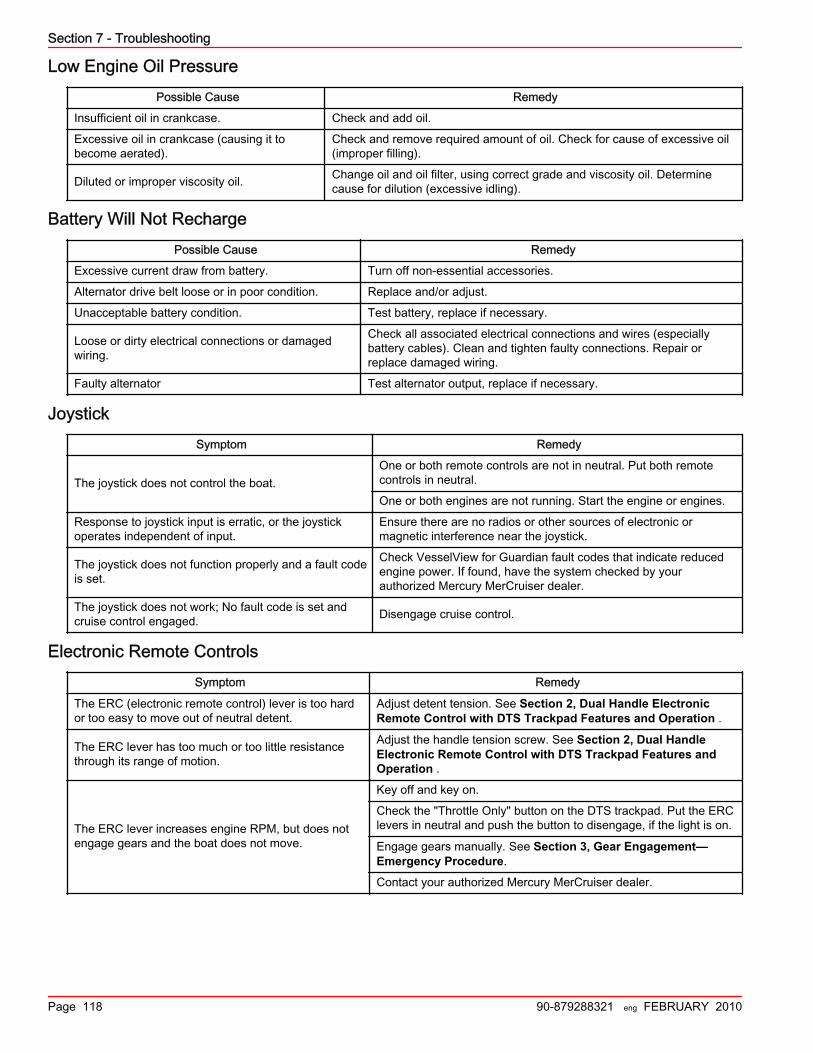
Section 7 - Troubleshooting
Page 118 90-879288321 eng FEBRUARY 2010
Low Engine Oil PressurePossible Cause Remedy
Insufficient oil in crankcase. Check and add oil.
Excessive oil in crankcase (causing it tobecome aerated).
Check and remove required amount of oil. Check for cause of excessive oil(improper filling).
Diluted or improper viscosity oil. Change oil and oil filter, using correct grade and viscosity oil. Determinecause for dilution (excessive idling).
Battery Will Not RechargePossible Cause Remedy
Excessive current draw from battery. Turn off non‑essential accessories.
Alternator drive belt loose or in poor condition. Replace and/or adjust.
Unacceptable battery condition. Test battery, replace if necessary.
Loose or dirty electrical connections or damagedwiring.
Check all associated electrical connections and wires (especiallybattery cables). Clean and tighten faulty connections. Repair orreplace damaged wiring.
Faulty alternator Test alternator output, replace if necessary.
JoystickSymptom Remedy
The joystick does not control the boat.One or both remote controls are not in neutral. Put both remotecontrols in neutral.
One or both engines are not running. Start the engine or engines.
Response to joystick input is erratic, or the joystickoperates independent of input.
Ensure there are no radios or other sources of electronic ormagnetic interference near the joystick.
The joystick does not function properly and a fault codeis set.
Check VesselView for Guardian fault codes that indicate reducedengine power. If found, have the system checked by yourauthorized Mercury MerCruiser dealer.
The joystick does not work; No fault code is set andcruise control engaged. Disengage cruise control.
Electronic Remote ControlsSymptom Remedy
The ERC (electronic remote control) lever is too hardor too easy to move out of neutral detent.
Adjust detent tension. See Section 2, Dual Handle ElectronicRemote Control with DTS Trackpad Features and Operation .
The ERC lever has too much or too little resistancethrough its range of motion.
Adjust the handle tension screw. See Section 2, Dual HandleElectronic Remote Control with DTS Trackpad Features andOperation .
The ERC lever increases engine RPM, but does notengage gears and the boat does not move.
Key off and key on.
Check the "Throttle Only" button on the DTS trackpad. Put the ERClevers in neutral and push the button to disengage, if the light is on.
Engage gears manually. See Section 3, Gear Engagement—Emergency Procedure.
Contact your authorized Mercury MerCruiser dealer.

Section 7 - Troubleshooting
90-879288321 eng FEBRUARY 2010 Page 119
Symptom Remedy
The ERC lever controls the engine and drive, but doesnot reach wide open throttle.
If the engine only reaches 50% of WOT, check the "DOCKING"button on the DTS trackpad. Put the handles in neutral and push thebutton to disengage, if light is on.
Check VesselView to see if cruise control enabled. Disable cruisecontrol.
Check for damage to the propeller. Check VesselView for Guardianfault codes that indicate reduced engine power. If found, contactyour authorized Mercury MerCruiser dealer to ask if the propellersneed to be changed.
The ERC lever controls the engine and drive, but doesnot respond in a linear manner.
Check the "TROLL" button on the DTS track pad. Put the handles inNeutral and push the "TROLL" button to disengage, if light is on.
Check whether dock mode or cruise control are on. If on, turn off ordisengage.
When one ERC lever is moved, both engines respond.Check the "1 LEVER" button on the DTS track pad. If the light is on,put the handles in neutral and push the "1 LEVER" button todisengage.
The ERC control, joystick, and steering wheel do notfunction.
Press "HELM" on DTS track pad to restore helm control. (Multiplehelm boats only.)
Steering SystemSymptom Remedy
The steering wheel steers the boat, but operates withoutresistance.
The starboard key switch is tuned off. Turn on the key.
Check and start the starboard engine.
Check if the starboard harness circuit breaker has tripped. Resetthe circuit breaker, if tripped.
Steering wheel does not steer the boat.
Reduce speed and change to joystick for directional control.
Check steering fluid level and fill if necessary. See Section 5—Maintenance.
Contact your authorized Mercury MerCruiser dealer.
Steering works, but the boat is not as responsive.
Key off and key on.
Check and start the port engine.
Check the trim tab function.
Check the steering fluid level and fill if necessary. See Section 5— Maintenance.
Contact your authorized Mercury MerCruiser dealer.
The steering wheel turned past end stop. Key off and key on to restore steering wheel self‑centering, cruisecontrol, and to eliminate the fault code.
Power Trim Does Not Operate (Motor Does Not Operate)Possible Cause Remedy
Blown fuse. Replace fuse. Fuses may be located near the dash trim switch, at the trim pump, in thepositive (red) power trim battery lead near the battery switch, or a combination of these.
Loose or dirty electricalconnections or damagedwiring.
Check all associated electrical connections and wires (especially battery cables). Clean andtighten faulty connection. Repair or replace wiring.

Section 7 - Troubleshooting
Page 120 90-879288321 eng FEBRUARY 2010
Power Trim Does Not Operate (Motor Operates but Sterndrive Unit Does Not Move)Possible Cause Remedy
Trim pump oil level low. Fill pump with oil.
Drive unit binding in gimbal ring. Check for obstruction.
Section 8 - Customer Assistance Information
90-879288321 eng FEBRUARY 2010 Page 121
Section 8 - Customer Assistance InformationTable of ContentsOwner Service Assistance.................................................. 122
Local Repair Service .................................................. 122Service Away From Home .......................................... 122Stolen Power Package ............................................... 122Attention Required after Submersion ......................... 122Replacement Service Parts ........................................ 122
Parts and Accessories Inquiries .......................... 122
Resolving a Problem .................................................. 122Mercury Marine Service Offices ................................. 123
Ordering Literature............................................................. 123United States and Canada ......................................... 123Outside the United States and Canada ...................... 124
Dealer Checklist and Customer Orientation....................... 124
8

Section 8 - Customer Assistance Information
Page 122 90-879288321 eng FEBRUARY 2010
Owner Service AssistanceLocal Repair Service
If you need service for your Mercury MerCruiser–powered boat, take it to your authorized dealer. Only authorized dealersspecialize in Mercury MerCruiser products and have factory‑trained mechanics, special tools and equipment, and genuineQuicksilver parts and accessories to properly service your engine.NOTE: Quicksilver parts and accessories are engineered and built by Mercury Marine specifically for Mercury MerCruisersterndrives and inboards.
Service Away From HomeIf you are away from your local dealer and the need arises for service, contact the nearest authorized dealer. Refer to theYellow Pages of the telephone directory. If, for any reason, you cannot obtain service, contact the nearest Regional ServiceCenter. Outside the United States and Canada, contact the nearest Marine Power International Service Center.
Stolen Power PackageIf your power package is stolen, immediately advise the local authorities and Mercury Marine of the model and serial numbersand to whom the recovery is to be reported. This information is maintained in a database at Mercury Marine to aid authoritiesand dealers in recovery of stolen power packages.
Attention Required after Submersion1. Before recovery, contact an authorized Mercury MerCruiser dealer.2. After recovery, immediate service by an authorized Mercury MerCruiser dealer is required to reduce the possibility of
serious engine damage.
Replacement Service Parts
! WARNINGAvoid fire or explosion hazard. Electrical, ignition, and fuel system components on Mercury Marine products comply withfederal and international standards to minimize risk of fire or explosion. Do not use replacement electrical or fuel systemcomponents that do not comply with these standards. When servicing the electrical and fuel systems, properly install andtighten all components.
Marine engines are expected to operate at or near full throttle for most of their life. They are also expected to operate in bothfresh and saltwater environments. These conditions require numerous special parts. Exercise care when replacing marineengine parts, because specifications are different from those of the standard automotive engine. For example, one of the mostimportant special replacement parts, is the cylinder head gasket. Marine engines cannot use steel‑type automotive headgaskets because saltwater is highly corrosive. A marine engine head gasket uses special materials to resist corrosion.Because marine engines must be capable of running at or near maximum RPM much of the time, they also have special valvesprings, valve lifters, pistons, bearings, camshafts and other heavy‑duty moving parts.Mercury MerCruiser marine engines have other special modifications to provide long life and dependable performance.
Parts and Accessories InquiriesDirect any inquiries concerning Quicksilver replacement parts and accessories to your local authorized dealer. The dealer hasthe necessary information to order parts and accessories for you if they are not in stock. Only authorized dealers can purchasegenuine Quicksilver parts and accessories from the factory. Mercury Marine does not sell to unauthorized dealers or retailcustomers. When inquiring on parts and accessories, the dealer requires the engine model and serial numbers to order thecorrect parts.
Resolving a ProblemSatisfaction with your Mercury MerCruiser product is very important to your dealer and to us. If you ever have a problem,question or concern about your power package, contact your dealer or any authorized Mercury MerCruiser dealership. If youneed additional assistance:1. Talk with the dealership's sales manager or service manager. Contact the owner of the dealership if the sales manager and
service manager have been unable to resolve the problem.2. If your question, concern, or problem cannot be resolved by your dealership, please contact Mercury Marine Service Office
for assistance. Mercury Marine will work with you and your dealership to resolve all problems.The following information will be needed by the Service Office:• Your name and address

Section 8 - Customer Assistance Information
90-879288321 eng FEBRUARY 2010 Page 123
• Daytime telephone number• Model and serial numbers for your power package• The name and address of your dealership• Nature of problem
Mercury Marine Service Offices are listed on the next page.
Mercury Marine Service OfficesFor assistance, call, fax or write. Please include your daytime telephone number with mail and fax correspondence.
Telephone Fax Mail
(405) 743 6566 (405) 743 6570Mercury MerCruiser3003 N. Perkins Rd.Stillwater, OK 74075
(905) 567 MERC (6372) (905) 567 8515
Mercury Marine Ltd.2395 Meadowpine Blvd.Mississauga, Ontario L5N 7W6Canada
(61) (3) 9791 5822 (61) (3) 9793 5880
Mercury Marine Australia132-140 Frankston RoadDandenong, Victoria 3164Australia
(32) (87) 32 32 11 (32) (87) 31 19 65
Marine Power - Europe, Inc.Parc Industriel de Petit-RechainB-4800 Verviers,Belgium
(954) 744 3500 (954) 744 3535
Mercury Marine - Latin America & Caribbean11650 Interchange Circle North,Miramar, FL 33025U.S.A.
(81) 53 423 2500 (81) 53 423 2510
Mercury Marine - Japan283-1 Anshin-choHamamatsu, Shizuoka 435-0005Japan
(65) 6546 6160 (65) 6546 7789
Mercury Marine Singapore72 Loyang Way, 508762Singapore
Ordering LiteratureBefore ordering literature, please have the following information about your power package available:• Model• Serial number• Horsepower• Year built
United States and CanadaFor information on additional literature that is available for your particular Mercury MerCruiser power package and how to orderthat literature contact your nearest dealer or contact us at:Mercury Marine PublicationsP.O. Box 1939Fond du Lac, WI 54936-1939(920) 929 5110Fax (920) 929 4894

Section 8 - Customer Assistance Information
Page 124 90-879288321 eng FEBRUARY 2010
Outside the United States and CanadaContact your nearest dealer or Marine Power Service Center for information on additional literature that is available for yourparticular Mercury MerCruiser power package and how to order that literature.Print or type your mailing address, which be used as your shipping label, and include your order and payment. Mail to:Mercury MarineAttn: Publications DepartmentW6250 West Pioneer RoadP.O. Box 1939Fond du Lac, WI 54936-1939USA
Dealer Checklist and Customer OrientationContact InformationDealer name and number
Dealer technician or salesperson's name
Boat Model and HIN
Customer name
Customer phone number
TVM Dealer
Inspect the starboard TVM steering clevis pin. ☐
Inspect the port TVM steering clevis pin. ☐
Engine Dealer
Inspect the starboard hydraulic steering fluid reservoir level. ☐
Inspect the port hydraulic steering fluid reservoir level. ☐
Helm Dealer
Inspect the joystick. ☐
Inspect the steering wheel and tilt mechanism. ☐
Inspect the VesselView, if equipped. ☐
Inspect the Axius trackpad, if equipped. ☐
Wet Test Dealer
Confirm vessel personality list. ☐
Ensure the steering wheel returns to center position during key "ON" of starboard engine. ☐
Perform IMU (compass) calibration and zero heading correction. ☐
Maneuver the boat to port by moving the joystick to full port. Ensure undesirable movement can be corrected byminimal operator joystick input. ☐
Maneuver the boat to starboard by moving the joystick to full starboard. Ensure undesirable movement can becorrected by minimal operator joystick input. ☐
Ensure vessel tracks a straight course at cruising speed. Perform drive alignment if required. ☐
Check steering response by steering boat from lock to lock at different speeds, starting at idle and acceleratingthrough cruising speed in 1000 RPM increments. ☐
Perform a hard starboard turn at in‑gear idle while increasing to WOT while in turn. Ensure boat steeringremains responsive. ☐
Perform a hard starboard turn at in gear idle with both engines running. Turn the starboard engine off during theturn. Ensure boat steering remains responsive. ☐

Section 8 - Customer Assistance Information
90-879288321 eng FEBRUARY 2010 Page 125
Wet Test Upgrades Dealer
Verify Auto Heading enable and disable, if equipped. ☐
Enable Auto Heading and drive for one minute at cruising speed ensuring less than 5° degree deviation to portor starboard. ☐
Verify Skyhook enable and disable, if equipped. ☐
Verify Waypoint Sequencing, if equipped. ☐
Safety Customer Dealer
Enable Throttle Only and demonstrate its ability to disable shifting of the electronic remote controland joystick while engines are running. ☐ ☐
Joystick Customer Dealer
Demonstrate that the joystick requires both engines to be running to operate. ☐ ☐
Rotate the joystick to port and starboard to demonstrate pivot capabilities. ☐ ☐
Place the joystick to port to translate the boat while demonstrating the ability to compensate forcurrent and wind by rotating the top of the joystick and inputting slight forward and reverse inputs.Repeat going starboard.
☐ ☐
Enable docking mode to demonstrate reduced throttle response for joystick maneuvers. ☐ ☐
Upgrades Customer Dealer
Demonstrate methods to enable and disable Auto Heading, if equipped. ☐ ☐
Demonstrate methods to enable and disable Skyhook, if equipped. ☐ ☐
Demonstrate methods to enable and disable AutoPilot Waypoint Sequencing, if equipped. ☐ ☐
Steering wheel Customer Dealer
Demonstrate that the starboard keyswitch is required to be on for steering wheel autocenter andforce feedback. ☐ ☐
Inform the consumer where the 20 A circuit breaker is located. ☐ ☐
Demonstrate the steering wheel autocenter ability and conditions. ☐ ☐
Maintenance Customer Dealer
Inform the consumer about hydraulic power steering fluid level checks and service intervals. ☐ ☐
NOTE: Refer to the installation or owners manual provided with this power package for detailed information on performing theitems in the above checklist.NOTE: Dealers, please consult Mercury MercNET or your Mercury Technical Area Manager for further information aboutsubmitting this form.