Embed Size (px)
Citation preview

December,2001 1
Simulation of Tightly Coupled INS/GPS Navigator
Ade Mulyana, Takayuki Hoshizaki
December, 2001
Purdue University
December,2001 2
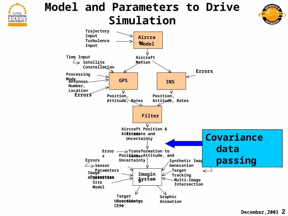
Model and Parameters to Drive Simulation
Aircraft Motion
Aircraft Model
Trajectory Input
Time Input
Turbulence Input
Errors
GPS
Satellite Constellation
Processing Mode
AntennasNumber, Location
Errors
INS Position, Attitude, Rates Position, Attitude, Rates
Filter
Aircraft Position & Attitude Estimate and Uncertainty
Transformation to Sensor Position, Attitude, and Uncertainty
Errors
ErrorsSensor Parameters
Image AcquisitionParameters
Site Model
Imaging System
Target CoordinatesUncertainty, CE90
Graphic Animation
Multi-ImageIntersection
Synthetic Image GenerationErrors
Target Tracking
Covariance data passing

December,2001 3
Outline
1. Overview
2. Structure of Simulation
3. Simulation Models
4. Kalman Filter
5. Initial Conditions
Error Source Specifications
6. Results
7. Conclusions

December,2001 4
Overview
(1)UAV Dynamics
Nominal Trajectory
(2) Navigation Equation
INS Output
(3) Tightly Coupled INS/GPS
INS/GPS Output
Covariance Data
(4) Covariance data is passed to Imagery Analysis

December,2001 5
GPS Receiver
IMU Nav
Structure of Simulation
Tightly Coupled INS/GPS
Position
Velocity
Orientation
Covariance
UAV
Kalman Filter
+
-
INS
Bias Correction
Position, Velocity, Orientation and Covariance correction

December,2001 6
Simplified IMU Model
äxxx~ −=where
äx = Bias + White Noise
: Sensor Output
: Sensor Input
Bias : Markov Process, tc=60s
for all
x~
x
⎩⎨⎧
ωωω=zyx
zyx
,,a,a,a
xAccelerometer Outputs
Rate Gyro Outputs
December,2001 7
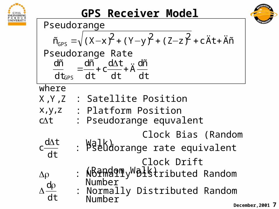
GPS Receiver Model
dt
dñÄ
dt
tdc
dt
dñ
dt
dñ
ÄñÄtc2z)(Z2y)(Y2x)(Xñ
GPS
GPS
+Δ
+=
++−+−+−=
: Platform Position
dt
d
dt
tdc
tcz,y,xZ,Y,X
where
ρΔ
ρΔ
Δ
Δ
: Satellite Position
: Pseudorange equvalent
Clock Bias (Random Walk)
: Pseudorange rate equivalent
Clock Drift (Random Walk): Normally Distributed Random Number
: Normally Distributed Random Number
Pseudorange
Pseudorange Rate

December,2001 8
Kalman Filter: Error Dynamics
]dt
tdct,c
,B,B,B,B,B,B
äh,äë,äö,,äv,äv,äv
äã,äâ,äá,[äx
dt
d
azayax
ùzùyùx
DEN
GväxFäx
ΔΔ
=
+=
Orientation Angle Errors
17 States Kalman Filter
Velocity Errors
Position Errors
Gyro Biases
Accelerometer Biases
Clock Bias and Drift
December,2001 9
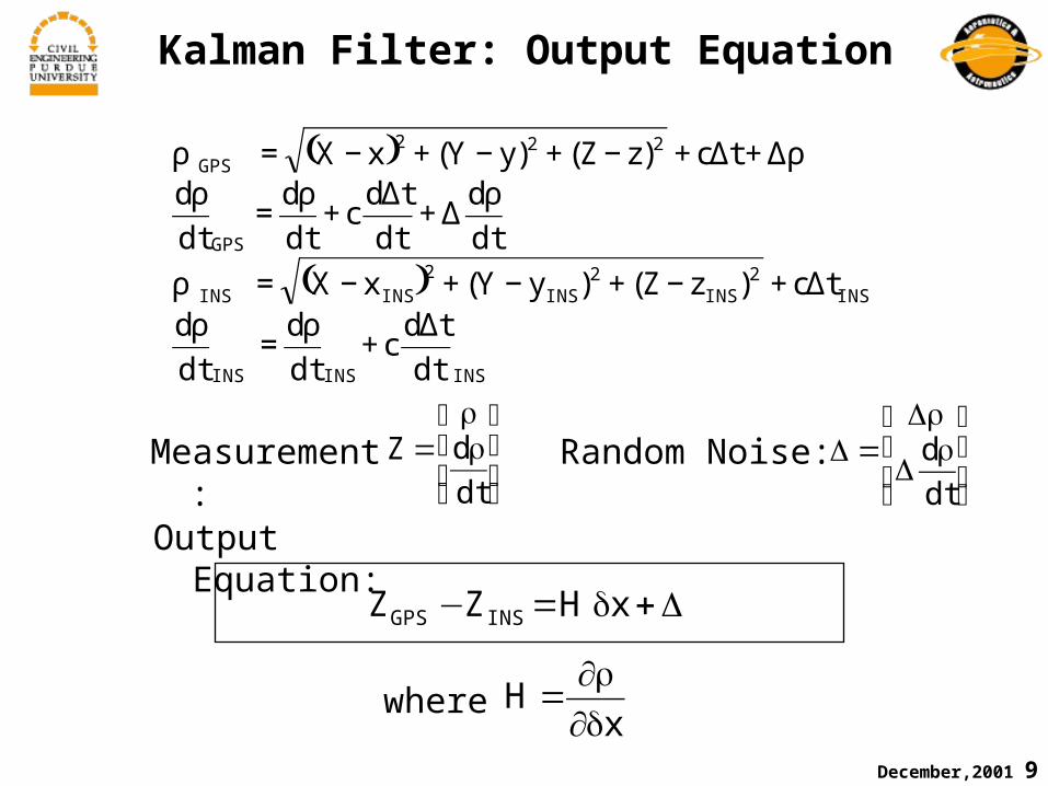
Kalman Filter: Output Equation
( )
( )
INSINSINS
INS2
INS2
INS2
INSINS
GPS
222GPS
dt
tdc
dt
d
dt
dtc)zZ()yY(xX
dt
d
dt
tdc
dt
d
dt
dtc)zZ()yY(xX
Δ+
ρ=
ρΔ+−+−+−=ρ
ρΔ+
Δ+
ρ=
ρρΔ+Δ+−+−+−=ρ
Measurement: ⎥⎥
⎦
⎤
⎢⎢
⎣
⎡ρρ
=dt
dZ Random Noise: ⎥⎥
⎦
⎤
⎢⎢
⎣
⎡ρ
Δ
ρΔ=Δ
dt
d
Δ+δ=− xHZZ INSGPS
Output Equation:
xH
δ∂ρ∂
=where

December,2001 10
Initial Error Condition
])s/m(,m[]S,S[)d,b(Pg)B(P
)s/rad()B(P
)s/m(]v,v,v[)v,v,v(Prad)],,[),,(P
)]s/m(,m[]S,S[]d,b[
g],,[]B,B,B[s/rad],,[]B,B,B[
m1hrad]7e57.1,7e57.1[],[
s/m]1.0,1.0,1.0[]v,v,v[rad]002.0,001.0,001.0[]3E,2E,1E[
thatso],,[
22db0
22aiai0
22ii0
20
2D0
2E0
2NDEN0
220
20
200
db0
BaBaBa0azayax
BBB0zyx
0
0
0DEN
000
000
=σ=σ=
δδδ=δδδδγδβδα=δγδβδα
=
σσσ=σσσ=
=δ−−=δλδφ
=δδδ=δδδ=δγδβδα
ωω
ωωωωωω
• Initial Errors
• Initial Covariance Values
December,2001 11
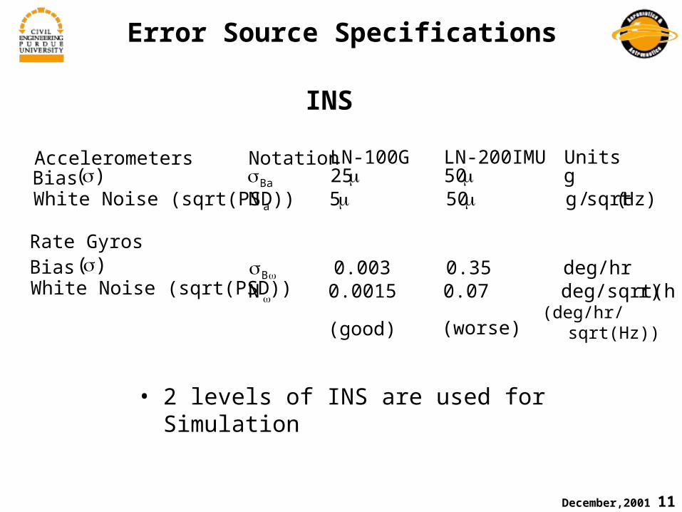
Error Source Specifications
r)deg/sqrt(h0.070.0015Ndeg/hr 0.35 0.003
)Hz(sqrt/g505Ng5025
B
a
Ba
ω
ωσ
μμμμσ
INS
AccelerometersBias White Noise (sqrt(PSD))
Bias White Noise (sqrt(PSD))
Notation LN-100G LN-200IMU Units
Rate Gyros
(good) (worse)
• 2 levels of INS are used for Simulation
)(σ
)(σ
(deg/hr/sqrt(Hz))

December,2001 12
Error Source Specifications
GPS
GPS Receiver Notation Receiver 1 Receiver 2 Units
Pseudorange 6.6 33.3 m
Pseudorange Rate 0.05 0.5 m/s
ClockBias White Noise(PSD) 0.009 0.009
ClockDrift White Noise(PSD) 0.0355 0.0355
rσ
rrσ
bS
dS
2m2)s/m(
)(σ)(σ
(good) (worse)
• 2 levels of GPS Receivers are used for Simulation

December,2001 13
Satellite Geometry during the Simulation

December,2001 14
Local Frame: x, y, z
Xecef
Yecef
Zecef
x
y
z
x=Zecef
y=-Yecef
z=Xecef-6378137m
Nominal Trajectory
)ft20000()m(6096h)s/ft200(
)s/m(61v
0
x
=
=

December,2001 15
Result 1:Comparisons between INS/GPS and Unaided INS;(Good INS,Good GPS)
0 50 100 150 200 250 300 350 400-500
0
500
1000Local Frame Position Errors
dx (m)
0 50 100 150 200 250 300 350 400-500
0
500
1000
dy (m) INS/GPS Error
Unaided INS Error
0 50 100 150 200 250 300 350 400-10
0
10
20
30
dz (m)
time (s)
Local Frame Position Errors: (true) – (estimated)
dx (m)
dy (m)
dz (m)
0 400 (sec)• INS/GPS works very well

December,2001 16
0 50 100 150 200 250 300 350 400-2
0
2
4Local Frame Velocity Errors
dvx (m/s)
0 50 100 150 200 250 300 350 400-2
0
2
4
dvy (m/s)
INS/GPS ErrorUnaided INS Error
0 50 100 150 200 250 300 350 400-0.1
0
0.1
0.2
0.3
dvz (m/s)
time (s)
Local Frame Velocity Errors: (true) – (estimated)
)s/m(dvx
)s/m(dvy
)s/m(dvz
400 (sec)0• INS/GPS works very well
Result 1:Comparisons between INS/GPS and Unaided INS;(Good INS,Good GPS)

December,2001 17
0 50 100 150 200 250 300 350 400-2
-1
0
1x 10
-3 Euler Angle Errors
dE1 (rad)
0 50 100 150 200 250 300 350 400-15
-10
-5
0
5x 10
-4
dE2 (rad) INS/GPS Error
Unaided INS Error
0 50 100 150 200 250 300 350 400-3
-2
-1
0x 10
-3
dE3 (rad)
time (s)
Local Frame Euler Angle Errors: (true) – (estimated)
droll (rad)
dpitch (rad)
dyaw (rad)
• Roll and Pitch errors are quickly corrected• Yaw error correction takes time
400 (sec)0
Effect on Geo Positioning?
Result 1:Comparisons between INS/GPS and Unaided INS;(Good INS,Good GPS)

December,2001 18
Result 2:Ensembles (Good INS,Good GPS)
Local Frame Position Errors: (true) – (estimated)
0 50 100 150 200 250 300 350 400-2
-1.5
-1
-0.5
0Local Frame Position Errors
dx (m)
0 50 100 150 200 250 300 350 400-4
-2
0
2
dy (m)
0 50 100 150 200 250 300 350 400-2
-1
0
1
2
dz (m)
time (s)
dx (m)
dy (m)
dz (m)
0 400 (sec)• Position error is less than 3m±
• Error value is not 0 mean locally
LN-100G:10mCEP
December,2001 19
0 50 100 150 200 250 300 350 400-0.1
-0.05
0
0.05Local Frame Velocity Errors
dvx (m/s)
0 50 100 150 200 250 300 350 400-0.1
-0.05
0
0.05
dvy (m/s)
0 50 100 150 200 250 300 350 400-0.1
-0.05
0
0.05
0.1
dvz (m/s)
time (s)
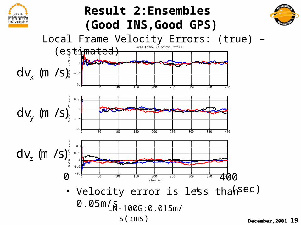
Result 2:Ensembles (Good INS,Good GPS)
0 400 (sec)
)s/m(dvx
)s/m(dvy
)s/m(dvz
Local Frame Velocity Errors: (true) – (estimated)
• Velocity error is less than 0.05m/s±
LN-100G:0.015m/s(rms)

December,2001 20
0 50 100 150 200 250 300 350 400-2
-1
0
1x 10
-3 Euler Angle Errors
dE1 (rad)
0 50 100 150 200 250 300 350 400-2
-1
0
1x 10
-3
dE2 (rad)
0 50 100 150 200 250 300 350 400-3
-2
-1
0
1x 10
-3
dE3 (rad)
time (s)
Result 2:Ensembles (Good INS,Good GPS)
0 400 (sec)
Local Frame Euler Angle Errors: (true) – (estimated)
droll (rad)
dpitch (rad)
dyaw (rad)
• Angle error is about 0.003 deg for roll and pitch,0.06 deg for yaw,
LN-100G:0.002deg (rms) for all pitch, roll and yaw

December,2001 21
Result 3: Comparisons between 4patterns
0 50 100 150 200 250 300 350 400-5
0
5
10Local Frame Position Errors
dx (m)
0 50 100 150 200 250 300 350 400-5
0
5
10
dy (m)
gIgGwIgGwIwGgIwG
0 50 100 150 200 250 300 350 400-10
-5
0
5
dz (m)
time (s)
0 400 (sec)
dx (m)
dy (m)
dz (m)
Local Frame Position Errors: (true) – (estimated)
blue red (:) black (-.) green (--)INS good worse worse goodGPS good good worse worse
• GPS performance directly affects position errors
200~300s covariance and nominal trajectory data are passed to imagery analysis

December,2001 22
0 50 100 150 200 250 300 350 400-0.1
0
0.1
0.2
0.3Local Frame Velocity Errors
dvx (m/s)
0 50 100 150 200 250 300 350 400-0.2
-0.1
0
0.1
0.2
dvy (m/s)
gIgGwIgGwIwGgIwG
0 50 100 150 200 250 300 350 400-0.1
0
0.1
0.2
0.3
dvz (m/s)
time (s)0 400 (sec)
)s/m(dvx
)s/m(dvy
)s/m(dvz
Result 3: Comparisons between 4 patternsblue red (:) black (-.) green (--)
INS good worse worse goodGPS good good worse worse
Local Frame Velocity Errors: (true) – (estimated)
• GPS performance directly affects velocity errors

December,2001 23
0 50 100 150 200 250 300 350 400-2
-1
0
1x 10
-3 Euler Angle Errors
dE1 (rad)
0 50 100 150 200 250 300 350 400-15
-10
-5
0
5x 10
-4
dE2 (rad)
gIgGwIgGwIwGgIwG
0 50 100 150 200 250 300 350 400-3
-2
-1
0x 10
-3
dE3 (rad)
time (s)0 400 (sec)
droll (rad)
dpitch (rad)
dyaw (rad)
Result 3: Comparisons between 4patternsblue red (:) black (-.) green (--)
INS good worse worse goodGPS good good worse worse
Local Frame Euler Angle Errors: (true) – (estimated)
• INS accuracy helps orientation accuracy
December,2001 24
Conclusions
• We have successfully built a realistic integrated INS/GPS which will be used to study the effects of navigation accuracy on target positioning accuracy.
• The INS/GPS is good at correcting roll and pitch angles, but not yaw angle.
• Improving GPS accuracy improves aircraft position accuracy. Improving INS accuracy improves aircraft attitude accuracy. Both aircraft position and attitude are needed to locate the target.

December,2001 25
Future Work
GPS
•Use of carrier phase observations
•Use of dual frequencies
•Differential carrier phase GPS
INS
•Estimate Scale Factor and Nonlinearity as well as Bias:
⎪⎭
⎪⎬⎫
⎪⎩
⎪⎨⎧
+⎪⎭
⎪⎬⎫
⎪⎩
⎪⎨⎧
+⎪⎭
⎪⎬⎫
⎪⎩
⎪⎨⎧
⎥⎥⎥
⎦
⎤
⎢⎢⎢
⎣
⎡=δ
z
y
x
z
y
x
z
y
x
zzyzx
yzyyx
xzxyx
DDD
BBB
aaa
SMMMSMMMS
ar

December,2001 26
References
(INS)
[1] Titterton, D. H. and Weston, J. L. (1997). “Strapdown Inertial Navigation Technology”. Peter Peregrinus Ltd.
[2] Rogers, R. M. (2000). “Applied Mathematics In Integrated Navigation Systems”. AIAA Education Series.
[3] Chatfield, A. B. (1997). “Fundamentals of High Accuracy Inertial Navigation”. Volume 174, Progress in Astronautics and Aeronautics. AIAA.
[4] Britting, K. R. (1971). “Inertial Navigation Systems Analysis”. Wiley Interscience.
(Kalman Filter)
[5] Brown, R. G. and Hwang, P. Y. C. (1985). “Introduction to Random Signals and Applied Kalman Filtering”. John Wiley & Sons.
[6] Gelb, A. (1974). “Applied Optimal Estimation”. M.I.T. Press.

December,2001 27
References (Cont.)
(Navigation Sensors)
[7] B. Stieler and H. Winter (1982). “Gyroscopic Instruments and Their Application to Flight Testing”. AGARDograph No.160 Vol.15.
[8] Lawrence, A. (1992). “Modern Inertial Technology”. Springer-Verlag.
[9] “IEEE Standard Specification Format Guide and Test Procedure for Single-Axis Laser Gyros”. IEEE Std. 647-1995.
(GPS)
[10] Kaplan. E. D. (1996). “Understanding GPS Principles and Applications”. Artech House.
(Others)
[11] Military Standard for Flying Qualities of Piloted Aircraft 1797A.
[12] Department of Defense World Geodetic System 1984, “Its Definition and Relationships with Local Geodetic Systems”, National Imagery And Mapping Agency Technical Report
December,2001 28
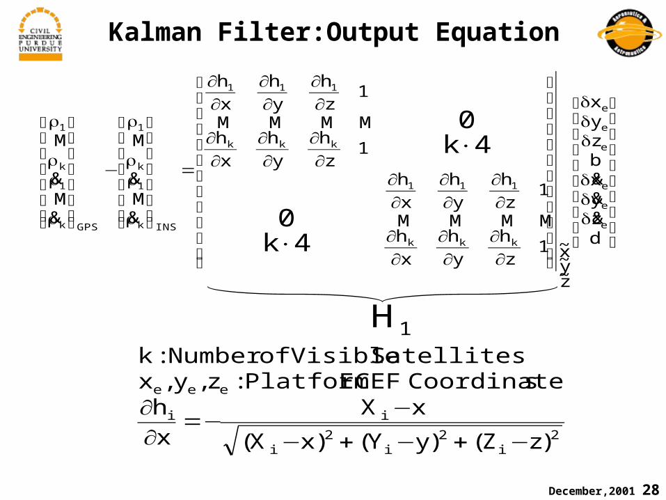
Kalman Filter:Output Equation
⎥⎥⎥⎥⎥⎥⎥⎥
⎦
⎤
⎢⎢⎢⎢⎢⎢⎢⎢
⎣
⎡
δδδ
δδδ
⎥⎥⎥⎥⎥⎥⎥⎥⎥⎥⎥
⎦
⎤
⎢⎢⎢⎢⎢⎢⎢⎢⎢⎢⎢
⎣
⎡
∂∂
∂∂
∂∂
∂∂
∂∂
∂∂
∂∂
∂∂
∂∂
∂∂
∂∂
∂∂
=
⎥⎥⎥⎥⎥⎥
⎦
⎤
⎢⎢⎢⎢⎢⎢
⎣
⎡
ρ
ρρ
ρ
−
⎥⎥⎥⎥⎥⎥
⎦
⎤
⎢⎢⎢⎢⎢⎢
⎣
⎡
ρ
ρρ
ρ
×
×
dzyxbzyx
z~y~x~1
z
h
y
h
x
h
1z
h
y
h
x
h
1z
h
y
h
x
h
1z
h
y
h
x
h
e
e
e
e
e
e
kkk
111
kkk
111
INSk
1
k
1
GPSk
1
k
1
4k0
4k0
&&&
MMMM
MMMM
&M&
M
&M&
M
1H
2i
2i
2i
ii
eee
)zZ()yY()xX(
xX
x
hsCoordinateECEFPlatform:z,y,x
SatellitesVisibleofNumber:k
−+−+−
−−=
∂∂

December,2001 29
Kalman Filter:Output Equation
x
340
340
340T
340
340
340
340
340
10000000
000
ECEFNED
01000000
000h
zzzh
yyyh
xxx
dzyxbzyx
e
e
e
e
e
e
δ
××××
××××
⎥⎥⎥⎥⎥⎥⎥⎥⎥⎥⎥⎥⎥
⎦
⎤
⎢⎢⎢⎢⎢⎢⎢⎢⎢⎢⎢⎢⎢
⎣
⎡
∂∂
λ∂∂
φ∂∂
∂∂
λ∂∂
φ∂∂
∂∂
λ∂∂
φ∂∂
=
⎥⎥⎥⎥⎥⎥⎥⎥
⎦
⎤
⎢⎢⎢⎢⎢⎢⎢⎢
⎣
⎡
δδδ
δδδ
&&&
]d,b,B,B,B,B,B,B,h,,,v,v,v,,,[x
azayaxzyx
DEN
ωωω
δδλδφδδδδγδβδα=δ2H

December,2001 30
Simplified IMU Error Model
Gyrosfor)hrdeg/0015.0(
tersAcceleromefor)g5(PSDNoiseWhite:Di
Gyrosforhrdeg/003.0tersAcceleromeforg25
ensemblesforSTDBias)(Bias:B
InputSensor:aOutputSensor:a
~DDD
BBB
aaa
SMMMSMMMS
a
where
2
2D
B
i
z
y
x
z
y
x
z
y
x
zzyzx
yzyyx
xzxyx
aaa~
μ=
μ=σ
⎪⎭
⎪⎬⎫
⎪⎩
⎪⎨⎧
+⎪⎭
⎪⎬⎫
⎪⎩
⎪⎨⎧
+⎪⎭
⎪⎬⎫
⎪⎩
⎪⎨⎧
⎥⎥⎥
⎦
⎤
⎢⎢⎢
⎣
⎡=δ
δ−=
essMarkovProc
rr
r
rrr0
December,2001 31
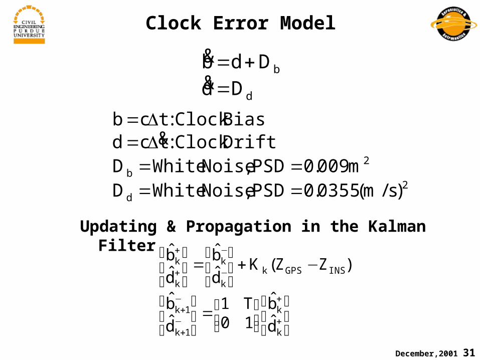
Clock Error Model
d
b
DdDdb
=+=
&&
2d
2b
)s/m(0355.0PSD,NoiseWhiteDm009.0PSD,NoiseWhiteD
DriftClock:tcdBiasClock:tcb
====
Δ=Δ=&
Updating & Propagation in the Kalman Filter
⎥⎦
⎤⎢⎣
⎡⎥⎦⎤
⎢⎣⎡=⎥
⎦
⎤⎢⎣
⎡
−+⎥⎦
⎤⎢⎣
⎡=⎥
⎦
⎤⎢⎣
⎡
+
+
−+
−+
−
−
+
+
k
k
1k
1k
INSGPSk
k
k
k
k
d̂
b̂10T1
d̂
b̂
)ZZ(Kd̂
b̂
d̂
b̂