Embed Size (px)
Citation preview
-1-
Dear MIFCO Customer:
We would like to thank and congratulate you on the purchase of the McEnglevanmachine and accessories, and to share with you our confidence in the quality and reliabilityof our equipment.
The enclosed Operating Manual and Warranty Registration Card are important toboth of us for two reasons:
l. Your Registration Card, with proper serial number, will be documented inour files and your written warranty will be forwarded to you upon the receiptof this card. Please complete and mail the return card now.
2. Proper instruction on the maintenance of your machine is very important.Please read your instruction manual completely for best results andmaximum machine tool life.
Should you ever need service, it is available through the distributors, our factoryrepresentatives or directly from the factory. It is the obligation of our franchised distributorwho sells you this equipment to conduct field service where possible. Please contactyour local distributor first and they will assist you in resolving any problems you mayencounter.
We take pride along with you in your purchase of this equipment. We will behappy to assist you in any way possible to receive optimum results in its operation anduse.
Sincerely yours,
Matt WalterCEO

-2-
Index
Model No. and Gas / Electrical Specifications ..................................................................................... 3
Furnace Installation and Set-Up ............................................................................................................. 4
Start-Up Procedure ..................................................................................................................................... 5
Instrument Quick Reference Guides:
Watlow F4 Controller and Watlow Series 97 High Limit Instruments ................................... 6
Honeywell UDC-2000 Control Instrument ................................................................................... 7
Honeywell UDC-3000 Programmable Control Instrument ...................................................... 8
Honeywell UDC-2000 High Limit Instrument .............................................................................. 9
Recording Instrument................................................................................................................................ 10
Audible Alarm ............................................................................................................................................... 11
Replacement Parts Lists (various models) ................................................................................ 12 to 17
HTG Relining Instructions ........................................................................................................................ 18
Trouble Shooting Guide .................................................................................................................. 19 to 22
Furnace Electrical Drawings .......................................................................................................... 23 to end

-3-
DO NOT REMOVE THIS PAGE
In accordance with the National Electric Code, A.G.A., Canadian Standard Association, O.S.H.A.,N.F.P.A., and the F.I.A. recommendations, this specification sheet must remain a part of this manual. Mostof the components are U.L. and A.G.A. listed.
This manual contains the Electrical Wiring schematic applicable to this particular equipment. If thereare any questions, contact your distributor or the factory. Only licensed electricians or qualified factoryrepresentatives should trouble shoot the electrical system of this equipment.
The electrical portion of this equipment is built in compliance with the National Electric Code in effect asof this date.
Purchased from ______________________________________ Date _________________
City __________________________________ State __________ Zip Code _________________
Model Number _____________________ Serial Number ________________________
Electrical Service Specifications
____________________ Volts _____________________ Phase ___________________ Hertz
Note: Schematic drawings showing different voltages, phase and hertz data are included in the manual.Use the above Electrical Service Specifications as your guide in selecting the correct schematic drawing.

-4-
Furnace Installation and Set-Up
1. Cut all banding, remove shrink wrap and remove furnace from skid. Be sure to locate hearth plate inpacking materials and set aside, if your furnace comes with one.
2. Set furnace in place, allowing at least 24 inches clearance around the unit on all sides. Larger unitsmay require bolting the furnace shell to the floor.
Units with Car Bottoms:If your unit is a car bottom style, locate the track into the furnace floor and bolt down - there will be pre-drilledholes. Anchor the outer end of the track to the floor of the building after the car travel has been tested. Besure to attach and wire the safety switches to the car track on the inside end of the track. Attach hydrauliclines to the car drive unit and door lift and fill hydraulic pump unit with hydraulic fluid.
3. Install gas line to unit according to local codes and regulations.
4. Install electrical power according to local code and regulations. See page 3 for electrical specificationsfor your furnace model.
5. Attach ventilation or exhaust piping if required. (Some models have exhaust dampers installed percustomer specifications.)
6. If your furnace has a water cooled bearing and a separate cooling unit, you will need to attach it to thefurnace. The unit will have two hoses with quick disconnect fittings. Attach these to the cooling lines on thefurnace. Plug the unit into a 120 volt AC outlet - some units will be wired directly into the control circuit toactivate upon furnace starting. If the coolant is shipped separately, be sure to add it to the unit.
7. Check rotation of chamber recirculating fan.
8. Attach inert gas supply if furnace has atmosphere inlet and set regulators. See page 13 - 14.
9. Refer to next page for Start-Up procedure.

-5-
Furnace Start-Up Procedure
MIFCO Heat Treat Furnaces are very easy to operate. They have been thoroughly tested andcalibrated at the factory. The following steps will get the furnace running and if you refer to the easy, onepage start-up guides for your particular instrument, the setpoints and programs can be entered. Included inthis manual are the instrument manuals for your particular furnace, from the manufacturer.
Start-Up1. Press the start button or flip the toggle switch to on. The instrument will go through a brief self diagnos-tic and then display the current temperature. If the furnace has a separate cooling unit for the water cooledbearing, be sure to turn it on also.
2. If there is a circulating fan bypass switch for cooling the high temperature chamber, make sure that it isin the off position. This will insure that when the door is opened while the chamber is in operation, the fanwill shut off to prevent accidents.
3. Enter a setpoint into the controlling instrument, per instructions for that instrument on the following pages.
4. If there is a high limit instrument, there must also be a setpoint entered into it that is 25 to 30 degreeshigher than the controlling instrument setpoint. This can also be left at its maximum temperature setting(default setting from the factory). The primary purpose of the high limit instrument is to protect the heatingpanels from overheating in the event of a problem with the main temperature controller. That is why thedefault is set to the chamber maximum setpoint at the factory. The secondary purpose of the high limit is toprotect parts being processed from going over a maximum setpoint, as a backup to the main temperaturecontroller.
5. The chamber should proceed to the setpoint and hold at temperature with no further adjustments.

-6-
ATTENTION: READ ME FIRST!!!Watlow F4 Temperature Controller
Programming the Control Instrument
First of all, the Watlow Control Instrument is pre-programmed here at the factory and has tuningparameters entered into it that have been arrived at by extensive testing. Everyone’s needs are differentand the control parameters chosen were decided on for a mixture of speed, to get the load up totemperature as fast as possible, and to minimize overshoot of the setpoint. You may decide to tunethe instrument to suit your needs more closely. This is a relatively easy process, but it is stronglysuggested that you read the accompanying book on your particular Watlow Controller FIRST.
To enter a setpoint into the controller, look at the lower display of the instrument. You will notice that theSetpoint 1 is the first parameter displayed. Use the right arrow to enter the setpoint. Use the up ordown arrows to determine the setpoint and right arrow again, after the setpoint is entered. The unitshould begin heating. This is all that is required.
Entering a Ramp / Soak Profile
(If you ordered Programmable Option #1 with your unit.)
The instrument is shipped from our factory with a sample profile that is named PROCESS 1. Itcan be viewed by going down the Main Page list in the lower display to the line that says Go to Profiles.Use the right arrow to go into the group. The display will read Create Profile, Edit Profile, DeleteProfile. Choose Edit Profile and use the right arrow to step through the existing profile. PROCESS 1is a simple 4 step profile for ramping the furnace up at 6:00 am to a setpoint of 1800°F. Step 1 has aramp time of 1 second, the lowest setting, to immediately change the setpoint. Step 2 is a 1 hour soakperiod to hold the load at the setpoint for a period of 1 hour. Step 3 is a 1 second ramp back down toa setpoint of 50°F. Step 4 is the end segment. This tells the controller what to do at the end of theprofile. In this case, we have programmed it to hold at the final setpoint. We employ the feature calledguaranteed soak, which delays timing of steps until the process temperature is within a specifiedrange of the setpoint.
There are other questions that have to be answered for each step when a profile is being createdthat tell it to perform certain functions, or to observe certain parameters. Refer to the sample profilepage on the next page of this manual to see the standard settings for these steps in this furnace. It isalso strongly suggested that you refer to the chapter on page 4.1, entitled Profile Programming, of theWatlow manual supplied with this operating manual for further details pertaining to creating profiles.
To run the profile, press the profile button in the lower left corner of the instrument. It will ask whichprofile you wish to run. Select the profile, right arrow out of the group, and the profile will start. You canconfirm this by referring to the lower display. Line 3 reads out the current step, line 4 tells the timeremaining for that step, and line 5 tells the actual time in 24 clock readout. To stop a profile, press theprofile button again and tell the instrument to terminate the profile. Right arrow out of the group and theprofile terminates. The Setpoint 1 reading will say OFF. Arrow down to the Setpoint 1 line and rightarrow into it, enter a setpoint again and right arrow out of the group and a new setpoint will be entered.
Watlow Series 97 High Limit Instrument
The high limit instrument supplied with your furnace is set at the factory to it’s maximum rangesetting. This is done to protect the heating elements in the furnace chamber. Should you wish to lowerthe setpoint of the high limit instrument, please refer to the Watlow Series 97 manual supplied with thismanual.

-7-
OPERATION OF HONEYWELL UDC-2000 SERIES CONTROLLERS
THIS IS INTENDED AS A QUICK REFERENCE GUIDE AND SHOULD NOT BESUBSTITUTED FOR READING THE PRODUCT MANUAL. THE PURPOSE OF THIS SHEET IS TOGET YOUR FURNACE RUNNING AND SIMPLIFY OPERATION IN THE BEGINNING.
Your instrument has been calibrated and tuned at the factory prior to shipping. There should be noneed for further adjustment in the field.
To begin with, the UDC-2000 is relatively simple to operate. To start the furnace, press the startbutton or flip the toggle switch. Then your instrument will power up and you will see the Process Temperaturedisplayed and either an “F” or “C” beside it, depending on the configuration requested. To enter a setpoint,press the display button marked DISP. The letters SP will appear in the lower left corner and the processtemperature will be replaced by the setpoint value.
To enter the setpoint press the up or down arrows, and the value will begin to change in onedegree increments. This process can be speeded up by pressing the opposite arrow while holding thefirst one in. Press once and the setpoint will increase by 10’s; once again and it will increase by 100’s.
Once you have obtained your desired setpoint, that is all you have to do. To return to Process orChamber Temperature Display, press RESET once and the process value will be displayed. If you donothing, it will return to Process value in about 1 minute. This is all you have to do. The furnace will beginheating immediately.
INDUSTRIAL FURNACES WITH HIGH LIMIT
Once you have followed the steps above, you must also enter a setpoint value in the High Limitinstrument. If the instrument display reads LIMIT you must first press RESET button. Then press thedisplay button marked DISP, and once again, as with the control instrument, SP will appear in the lower leftof the display, and what was your process value or chamber temperature will now become your setpointvalue. Enter a setpoint approximately 10° higher than the setpoint in the control instrument. Once you haveobtained a setpoint value the display will return to Process value in about 1 minute. If the high limit instrumentis engaged, the main contactor will be released and the display will read LIMIT. It must be reset after theprocess temperature goes below the setpoint to restart the furnace.
If you have any questions, please feel free to call McEnglevan or Honeywell’s toll free number foundinside the front cover of the instrument operating manual.

-8-
OPERATION OF HONEYWELL UDC-3000 SERIES CONTROLLERS
Entering a Single SetPointIn order to set a single setpoint, the setpoint program must not be running. This would be indicated
by an H in the upper display, to the left of the process temperature readout. To enter a setpoint, press theLOWR DISP button until SP is in the lower display. Press the up or down (arrow) buttons until the desiredsetpoint reads out in the lower display. The furnace will automatically start going to that setpoint.
Entering a ProgramThe setpoint program section of the UDC-3000 consists of 12 segments. These segments are
divided into 6 ramps and 6 soaks. Each ramp and soak can be programmed to take up to or last for 99hours. The UDC-3000 allows you to select the starting segment and ending segment so that a variety of‘mini” programs can be selected. For example, you could tell the instrument to start on segment 1 and endon segment 4. You must always end on a soak segment which are even numbered segments.
To program the ramps and soaks, press the SET UP key until SP RAMP appears in the lowerdisplay. Then press the FUNC (FUNCtion) key until SP PROG appears in the lower display. When it does,press either the up or down (arrow) button and enable it. This will appear in the upper display. When setpoint programming has been enabled, press the FUNCtion key until SEG 1 RAMP appears in the lowerdisplay. Then press the up or down keys until the desired hours or minutes are displayed in the upperread-out. Press FUNC again and SEG 2 SP will appear in the lower display. Now choose the tempera-ture that the first ramp will go to. Then press FUNC again and SEG 2 TIME will appear below. Choose thedesired time for the soak. Continue in this manner until you have programmed all the ramps and soaksdesired. When you are finished, press FUNC until you arrive back at STRT SEG in the lower display. Nowyou can choose which segment to start on. Press FUNC again and END SEG will appear. Choose theending segment desired. Press FUNC again and select the number of times you wish the program to run.If only once is required, choose “0' recycles. Press FUNC again and SOAK DEV will appear. Choose thenumber of degrees desired for deviation. If a value of 20 degrees is chosen, for example, the soak will beon hold as long as the process temperature is outside the 20 degree range above or below set point. Thisis helpful if too short a ramp time has been chosen. The soak will wait until the process temperature isclose to the set point before it begins. This is called “guaranteed soak’.
You are now ready to run the program. Press the run/hold button and an R will appear to the left ofthe process temperature. The lower read-out will display SP and a starting set point. To check your pro-gramming, press the LOWR DISP key and it will read-out first, the deviation from the current set point.Press it again and the segment number and time remaining will appear. Press it again and the percentageof power being applied to the elements will read-out. When the ramp set point is ahead of the processtemperature, the power will be fluctuating. Press the display key one more time and the set point willre-appear.

-9-
OPERATION OF THE HONEYWELL UDC-2000 HIGH LIMIT
THIS IS INTENDED AS A QUICK REFERENCE GUIDE AND SHOULD NOT BESUBSTITUTED FOR READING THE PRODUCT MANUAL. THE PURPOSE OF THIS SHEET IS TOGET YOUR FURNACE RUNNING AND SIMPLIFY OPERATION IN THE BEGINNING.
INDUSTRIAL FURNACES WITH HIGH LIMIT
Once you have started your furnace and entered a setpoint in the control instrument, you must alsoenter a setpoint value in the High Limit instrument. If the instrument display reads LIMIT you must firstpress RESET button. Then press the display button marked DISP, and once again, as with the controlinstrument, SP will appear in the lower left of the display, and what was your process value or chambertemperature will now become your setpoint value. Enter a setpoint approximately 20o to 25o higher than thesetpoint in the control instrument. Once you have obtained a setpoint value the display will return to Processvalue in about 1 minute. If the high limit instrument is engaged, the main contactor will be released and thedisplay will read LIMIT. It must be reset after the process temperature goes below the setpoint to restartthe furnace.
If you have any questions, please feel free to call McEnglevan or Honeywell’s toll free number foundinside the front cover of the instrument operating manual.

-10-
RECORDING INSTRUMENT
The recording instrument is powered by a toggle switch located next to the instrument or, in someunits, will be wired to come on with the control instruments. The instrument can record one or both chamber’sprocesses. Input 1 is the upper chamber and input 2 is the lower chamber. To avoid a print-out on anunused chamber, the inputs can be disabled. All operating parameters have been entered here at thefactory, but the time will have to be set upon arrival. Please refer to the instrument manual for procedures.
This instrument, as well as the programmable instruments, have internal lock-out features. Theseare used to prevent un-authorized tampering with control parameters. None of these lock-outs have beenactivated. To activate lock-out, please refer to the instrument manuals.

-11-
INSTRUMENTATION WITH AUDIBLE ALARM
Programming for Honeywell InstrumentsA sample program is entered into the instrument memory at the factory to demonstrate how the
audible alarm works. The sample program consists of 1 minute ramps and soaks. At the end of a soaksegment, there is a 1 minute ramp used for the alarm segment. The audible alarm is a programmed“event” alarm. This means that at the beginning of the chosen alarm segment, the relay for the bell willclose, and the bell will be energized. At the end of the segment, the relay will open and the bell will bede-engergized. One minute is the shortest time that can be programmed, so a toggle switch is provided toturn the bell off. The operator must remember to turn the toggle switch back on so that the alarm will ringagain in the next program. Power to the bell is indicated by a light below the toggle switch.
To change the alarm segment number, press the set up button until alarms appears in the lowerdisplay, then press the function button. AlSlVAL will appear in the lower display. A number is entered.This is the segment that the alarm contact is energized at the beginning of. Press function again andAlS2VAL will appear. This is the segment that the alarm contact is de-energized at the end of.
A segment could probably be saved by changing the alarm values. To do this, change AlSlVAL tothe segment number needed for the alarm to sound on at the end. Then change AlSlHL to end. This wouldallow the alarm to sound at the end of the desired segment, then it would have to be turned off by the toggleswitch. Upon a new cycle start up, the toggle switch would have to be turned back on.

-12-
HTG-94 PARTS LIST
300012 HTG-94 burner assembly003378 1½" 90 degree elbow003280 1½” tee300013 1½" pipe nipple 24¼" long003126 1½" nipple x 4½" Iong300014 1½" pipe nipple x 17¼" long003122 1½" pipe x 5" long003385 2 x 1½” 90 degree elbow003121 1½" close nipple003421 1½" air gate valve003129 1½" nipple x 6 2" long006001 1½" gas air mixer003341 1" to 3/4" bushing003072 3/4" nipple x 7" long003375 3/4" 90 degree elbow003061 3/4" close nipple003064 3/4" x 3" nipple004244 3/4" zero governor003066 3/4" nipple x 4" long003452 3/4" gas shut off cock003369 1½” union
#175 blower004249' 1½" butterfly valve003519 P100 observation port006620 1" x 6½" burner nozzle assm003885 Amp terminal block -14 terminals003987 6' power cord003600 Buss fuse holders003624 2A glass fuse003662 Black start switch003663 Red stop switch004104 Fireye chassis004105 Fireye base unit004107 UV-1A6 flame scanner003707 7/8 cord bushing004024 UDC-2000 Honeywell digital controller003932 2 pole contactor 45CA20AF003925 single overload relay004041 8" Marshall tip004050 Thermocouple head assm004226 Low pressure air switch003892 Solid state timer 17 second003915 Ignition transformer004212 ¼" solenoid valve003906 Red indicator light004172 Honeywell damper motor003908 Indicator light, amber004214 3/4" gas solenoid valve004069 Straight connector for spark wire004070 Angle connector for spark wire003744 Spark wire - 6ft003689 Lodan connector ETC NC1610003705 7/8"snap bushing003704 3/4" anti short bushing003758 3/8" screw in connector003757 3/8" 90 degree elbow003811 29/64 conduit 3/8" flexible004205 control box knob

-13-
HTG-94 PARTS LIST
008065 Burner brick008050 Section side liner brick -8008070 Side spacer brick-6008069 5" flat spacer- 5008074 Exhaust liner brick-1008068 End Section top-4008071 5" tip end spacer-2008072 Side end spacer-4008073 5" bottom end spacer - 2008066 Left hand end section-2008067 Right hand end section-2008075 Back wall liner brick-2008190 25# Matrilite insulation cement008253 11" w x 14½" long hearth plate032017 HTG-94 relining kit complete with hearth plate

-14-
HTG-96 HEAT TREAT FURNACEPARTS LIST
PART N0. DESCRIPTION N0. PCS.
300091 Right Door Guide Angle 1300092 Door Guide Stop 1
300100 Left Door Guide Stop Assembly300101 Left Door Guide Angle 1300092 Door Guide Stop 1
300110 Door Pivot Assembly300111 Large Arc 1300112 Large Arc Legs 2300113 Pivot Hub 1300114 Small Arc Legs 2300115 Small Arc 2300116 Hub Bushing, 1300117 Frame Spacer 1001217 Door Pivot Bolt 1002015 Door Pivot Nut 1000408 Chain Lock Bolt 1002006 Chain Lock Nut 1
300120 Chain Assembly002459 Chain Clevis 2300121 Chain 64½"300122 Chain Handle 1000408 Chain Bolt for Handle 1002006 Chain Bolt Nut 1
300130 Foot Lift Assembly300131 Foot Pedal 1300132 Foot Pedal Support Bar 1300133 Door Lift Pipe 1300134 Door Lift Rod 1300135 Door Lift Spring 1002460 Rod Eye 2" Thread 1002126 Door Lift Pipe Washer 1
300440 Short Manifold Assembly300441 Manifold Pipe 1002452 Freeze Plug E 1003213 Half Coupling 3006620 Burner Nozzle Assembly 3
300450 Long Manifold Assembly300441 Manifold Pipe 1002452 Freeze Plug 1003213 1" Half Coupling 3006620 Burner Nozzle 3
008065 HB-1 Burner Brick 6008050 B10-SL Solid Side Liner Brick 9008070 F-14 Side Spacer Brick 8008069 F-13 Top & Bottom Spacer Brick 6008074 F-18 Exhaust Brick 2

-15-
HT-96 HEAT TREAT FURNACEPARTS LIST
PART N0. DESCRIPTION N0. PCS.
008068 F-12 Upper End Bricks 4008071 F-15 Upper End Spacers 2008072 F-16 Side Spacers 2008073 F-17 Bottom End Spacers 2008074 F-11 Bottom Right Hand Ends 2008066 F-10 Bottom Left Hand Ends 2008075 F-19 Rear Wall 2008171 Pearlite Insulation 20#008170. Vermiculite Insualtion. 15#008175 Incore Cement 354008172 Castable for Door 20#008254 Hearth Tile 11 x 19 1008300 Paint 1/10 Gal.
300310 HT-96 Burner Assembly004320 #175 Blower 1003378 1½" 90 Degree Elbow 2003293 1½" x 2 x 1½" Tee 1003131 1½" Pipe Nipple 25¼" Long 1003126 1½” Pipe Nipple 4½" Long 2003161 2" Pipe Nipple 17" Long 1003141 2" Pipe Nipple 2½" Long 1003148 2" Pipe Nipple 6" Long 1003379 2" 90 Degree Elbow 3003140 2" Close Nipple 2003432 2" Air Valve Brass Gate 1003148 2" Nipple 6" Long 1006002 65-4 North American Gas air Mixer 1003342 1¼" to 1" Reducing Bushing 1003376 1" 90 Degree Elbow 2003085 1" Close Nipple 1003086 1" x 2" Nipple 2006020 1" Zero Govenor 1903096 1" x 9" Nipple 1003453 1" Gas Shut Off Cock 1004002 10 AMP Snap Switch 1004001 6' Power Cord 1004060 Power Cord Bushing 1004086 Wire Nuts 5004027 16 Ga. MTW Ware 5'004068 Wiring Ties Panuit SST 1.5M 4002457 Pressed Steel Valve Handle 1003369 1½" Railroad Union 1003370 2" Railroad Union 1006007 ½" Air Volume Control Rod 1

-16-
HTG-98 GAS FURNACE PARTS LIST
Part # Qty. Description
300620 1 Steel assembly-includes shell, base, front /back plate300630 1 Base assembly300650 1 Shell assembly-includes shell,burner guide tubes, sleeve, ring, front /back plate300060 1 Front plate assembly300070 1 Back plate assembly401856 1 Thermocouple collar assembly010096 8 Burner guide tubes 1 5/8" tube x 4.75" lg003519 1 P-100 observation port300120 1 Chain assm300130 1 Foot lift assembly300660 1 Short manifold assembly-includes pipe,freeze plug, couplings, burner nozzle002452 2 1 3/4" expansion plug003213 8 1" blk half coupling006620 8 1" x 6½" burner nozzle300670 1 Long manifold-includes pipe, ends, couplings, nozzle003211 1 ½" half coupling004250 1 2" butterfly valve006002 1 2" gas air mixer 3065-4-14004245 1 1” zero governor R600SZ-88003453 1 1" gas cock004117 1 ½ HP Baldor motor #VL1303 for 115/230 volt 1 phase furnaces only004118 1 ½ HP Baldor motor #VM3107 for 230/460 volt 3 phase furnaces only003885 1 AMP terminal block 14 terminals003987 1 6' power cord003600 1 Buss fuse holders, HKP-HH003624 1 2A Glass fuse Buss AGC003662 2 Black start switch003663 2 Red stop switch004104 1 Fireye Chassis UVMlD004105 1 61 3060 Fireye Base Unit only004107 1 UV-1A6 Fireye flame scanner004024 1 UDC-2000 digital Honeywell controller003932 1 Contactor 2 poles, 120V, 20amp, 45CA20AF003925 1 Single overload relay 48DA17AA4, 30 amp004031 1 Type K 12" Thermocouple004050 1 Thermocouple head assembly004226 1 Dwyer low pressure air switch003892 1 Solid state time, 17 second FIS-5117003915 1 Ignition transformer004212 1 1/4" Solenoid valve003906 1 Red indicator light004174 1 Honeywell damper motor M436A 1090 with bag assembly #7640 JL003908 1 Amber indicator light004215 1 1" low pressure solenoid valve004069 1 Straight connector for spark wire004070 1 Angle connector for spark electrode004071 1 6UV spark igniter003689 2 NTC 1610 Lodan connector003705 3 7/8" snap bushing003704 2 3/4" anti short bushing003758 1 3/8 screw in connector003757 2 3/8 90 degree elbow 7380V003811 2' 29/64 conduit F500 3/8" flexible004205 1 Control box knob400150 1 Control box assembly004048 5' Thermocouple wire J-20-7-502

-17-
HTG-98 Parts List cont.
Part # Qty. Description
003502 2 Superior ball joint008065 8 Burner. bricks008050 11 Side liner bricks008070 10 Spacer bricks008069 8 5" flat spacer brick008074 2 Exhaust liner brick008071 2 5"top end spacer008073 2 5" bottom end spacer008067 2 Right hand end section008066 2 Left hand end section008068 4 End section008075 2 Back wall liner brick008072 4 Side end spacer brick008190 5 25# Bags of Matrilite insulation008255 1 Hearth plate

-18-
RELINING INSTRUCTIONSFOR HTG-94, 96, 98
STEP 1Place furnace shell on its back. Find row 6 of brick lower down into the bottom of shell. Note that insulation is in place.
Line up the hole in bricks with the hole in the bottom of shell.
STEP 2Find enclosed two boxes of RS Sealer. Mix both boxes together. This must be pretty thick to start with. After all
bricks are in place, you will thin down the remainder of the mix, and paint the entire liner, filling all cracks.
STEP 3Be aware that one burner brick has a pilot hole. Be sure that it is located, in row 2 in alignment with the pilot hole in
side of shell.
STEP 4Locate bricks which make up row 5. Start by cementing burner brick in place over the guide tube. Then place in the
exhaust brick F-18 as shown. Cement rest of row in place as shown in drawing.
STEP 5Special note on row 4: Find three special bricks which are used to make the hearth support rest in center of this row
in the bottom. This brick must not be any higher than the hearth ledge found in the bottom row 6.
STEP 6Continue cementing rows 3 and 2 in place. Make sure that row 1 is placed in position level across the bottom so that
face plate will go down over the bricks. Make sure there is cement between all rows of, bricks.
STEP 7Let the furnace sit for 24 hours so that the sealer will set up. Mix all together the pre-mixed insulation, found in one
drum. Use 10 gallons of water. Do not allow this mixture to be very thin, otherwise the cement will separate and will not bondtogether. Prod insulation down around the burner bricks, make sure there is no air pockets. Insulate up to the top of row 1. Letstand until it settles down, add more insulation up to the edge of the shell, then place top plate of furnace in position with care.Bolt in place.
STEP 8Now thin down your remaining sealer mixture with water, like latex paint. Paint entire inside of chamber with this
mixture. Let set up overnight, then place back on its stand.
Note: In between layers of bricks make sure that RS Sealer is not too thick. Otherwise the layers of bricks will gain height.

-19-
SERVICING - TROUBLE SHOOTING:
Problems with MIFCO furnaces with Fireye Controls can be easily isolated by following the approvedprocedure in the sequence given below. Before starting any trouble shooting, however, make sure of thefollowing:
1. Installation and wiring has been made in accordance with the manufacturer’s instructions.2. The Fireye Chassis is securely plugged in and the top and bottom retaining screws are tightened.
The Lockout Switch (red pushbutton) is reset.
In the following list, problems are listed first, and the possible causes are listed below in numericalorder. Refer to the manufacturer’s instruction manual included in this operating manual for proper componentand contact identification. It is necessary to have a 20,000 ohm, DC volt meter to perform signal testing.This meter, set on 150 volt AC scale, may be used to check line and load voltages at the identified terminalstuds on the components.
A. FURNACE WILL NOT START:
1. No voltage at start button or at UV terminals S1 and S2:a. Power cord not plugged into outlet.b. No power at outlet, (check with meter).c. Disconnect switch is off that feeds outlet.
d. Broken wire between outlet and control box.e. Blown fuse that feeds circuit breaker.f. Check the 2 amp control fuse.
2. Insufficient voltage at UV terminals S1 and S2:a. Minimum voltage is 102 volt - 50/60 cycle.b. Maximum voltage is 132 volt - 50/60 cycle.
3. No voltage to coil of motor starting relay R-1:a. With volt-meter, check wires to relay coil from start / stop buttons.
4. Unit not properly grounded.
B. MOTOR STARTING AND HOLDING RELAY WILL NOT OPERATE:
1. No action when start button is activated:a. Check for voltage on either side of start button. If there is no voltage, replace the bad switch.b. Check relay coil, gray wire, for voltage.
C. HOLDING RELAY WORKS BUT MOTOR DOES NOT RUN:
1. Check motor overload:a. Check with voltmeter to see if power is passing through to motor. Check from ground to
overload.b. Push the reset button on the motor overload.c. Check the heater element on the top of the motor overload to see if it is burnt in half.d. Examine relay contacts.

-20-
D. THE MOTOR RUNS, BUT THE SPARK DOES NOT COME ON:
1. Check the spark plug for power:a. Remove the spark plug cap. Hold this cap by the outside corner and hold the cap up to a
metal part of the furnace and push the start button to see if there is a spark at the cap.
2. Check the air pressure switch:a. Remove the junction box cover on the top of the air pressure switch (004226). Place both
wires inside on the same terminal, this will by-pass the switch. If you get a spark when youpress the start button, you know the switch is bad.
b. With the air switch by-passed and the motor running, check UV terminals 2 & 4 for linevoltage, 120V. If no voltage is present, replace UV chassis.
3. Check the spark plug:a. Pull off the spark wire and hold by the outside corner of the connector cap. Hold the metal
part of the cap close to the burner and press the start button. If it sparks, the transformeris OK. If not, check the spark wire connections on both ends and try again. If there is still nospark and there is 120 volts-on terminals 2 & 4, then you should replace the spark transformer.
4. The spark plug does not fire:a. Remove the plug and look for cracks in the porcelain insulator. If it is cracked, replace with
the same electrode.b. If the plug is not cracked, install it back in the furnace. The gap between the wire tip of the
plug and the end of the burner nozzle should be 1/16" to 1/8". This can be adjusted bybending the electrode wire, swiveling the electrode, and then tightening the clamping nut to
hold it in place. Observation can be made with a mirror inside the furnace or through the UVScanner observation port. In either case, BE SURE THE GAS IS OFF.
E. THE MOTOR RUNS, THERE IS A SPARK, BUT NO GAS:
1. Scanner does not see spark:a. Remove the scanner to see if the sight tube is blocked.b. Wipe off scanner bulb with soft cloth or tissue and replace.
2. Broken Scanner wire:a. Check for cuts or mashed conduit.
3. Ignition signal testing using a 20,000 ohm per volt DC volt meter:a. Connect the meter to terminals S1 & S2.b. Set the volt meter on the 10 volt DC scale and initiate a normal start up, but with the gas
valve CLOSED. The meter should read between 41/2 and 5 volts. If the-meter goesbackwards, reverse the leads. If the reading is less than 41/2 volts, the scanner needs to be
replaced.
F. GAS SOLENOID WILL NOT OPEN:
1. After checking all of the above, check terminals 2 & 3 on UV Chassis for line voltage:a. Put the volt meter back on the AC-250 volt scale and put the leads on terminals 2 & 3. Start
the furnace, and when the unit goes to Main Flame, terminal 3 should be energized, reading120 volts. If it is not, and every thing else proves out, the chances are that the UV Chassisis bad and needs replacing.
-21-
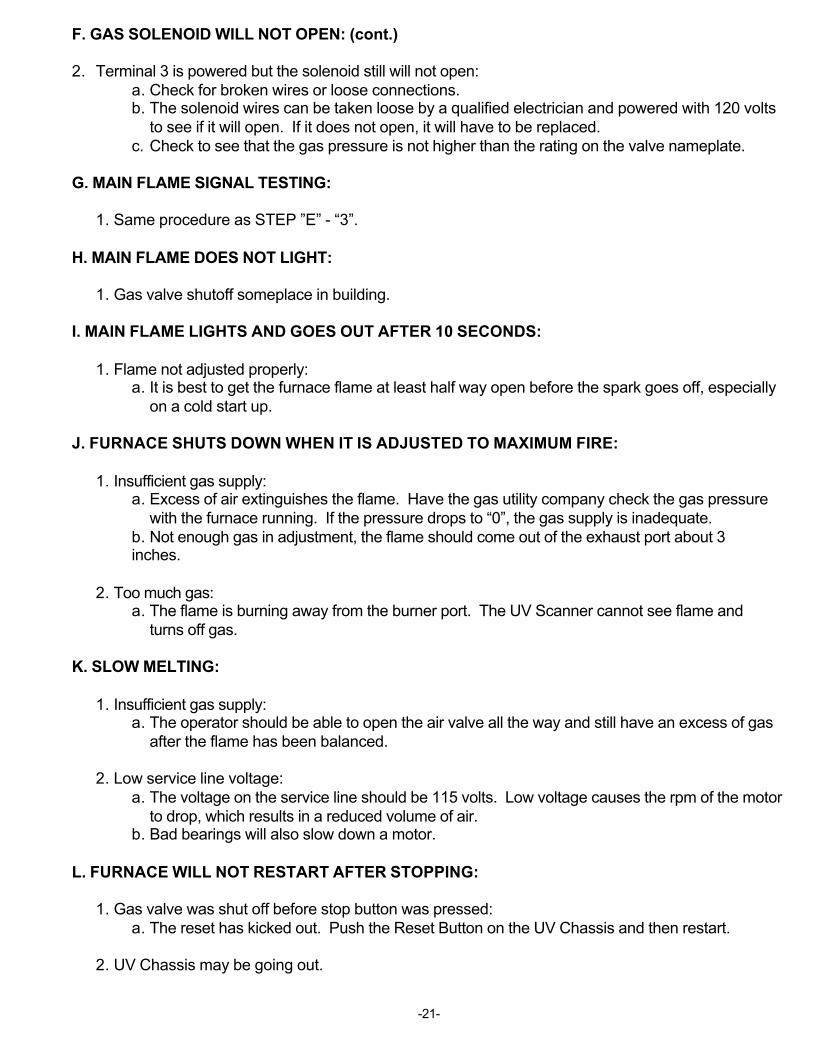
F. GAS SOLENOID WILL NOT OPEN: (cont.)
2. Terminal 3 is powered but the solenoid still will not open:a. Check for broken wires or loose connections.b. The solenoid wires can be taken loose by a qualified electrician and powered with 120 volts
to see if it will open. If it does not open, it will have to be replaced.c. Check to see that the gas pressure is not higher than the rating on the valve nameplate.
G. MAIN FLAME SIGNAL TESTING:
1. Same procedure as STEP ”E” - “3”.
H. MAIN FLAME DOES NOT LIGHT:
1. Gas valve shutoff someplace in building.
I. MAIN FLAME LIGHTS AND GOES OUT AFTER 10 SECONDS:
1. Flame not adjusted properly:a. It is best to get the furnace flame at least half way open before the spark goes off, especially
on a cold start up.
J. FURNACE SHUTS DOWN WHEN IT IS ADJUSTED TO MAXIMUM FIRE:
1. Insufficient gas supply:a. Excess of air extinguishes the flame. Have the gas utility company check the gas pressure
with the furnace running. If the pressure drops to “0”, the gas supply is inadequate.b. Not enough gas in adjustment, the flame should come out of the exhaust port about 3inches.
2. Too much gas:a. The flame is burning away from the burner port. The UV Scanner cannot see flame and
turns off gas.
K. SLOW MELTING:
1. Insufficient gas supply:a. The operator should be able to open the air valve all the way and still have an excess of gas
after the flame has been balanced.
2. Low service line voltage:a. The voltage on the service line should be 115 volts. Low voltage causes the rpm of the motor
to drop, which results in a reduced volume of air.b. Bad bearings will also slow down a motor.
L. FURNACE WILL NOT RESTART AFTER STOPPING:
1. Gas valve was shut off before stop button was pressed:a. The reset has kicked out. Push the Reset Button on the UV Chassis and then restart.
2. UV Chassis may be going out.

-22-
L. FURNACE WILL NOT RESTART AFTER STOPPING: (cont.)
3. Gas supply marginal and / or fluctuates:a. When starting with the valves in a set position and the gas supply or pressure changes, like
when a boiler comes on, the valve setting would not be right and the unit would not start.
M. FURNACE WILL NOT START AFTER FLAME FAILURE:
1. Not enough time has elapsed for blower to stop spinning and allow the air switch to reset:a. Allow blower to stop spinning then press reset button on UV Chassis.
2. Bad UV Chassis.
3. Bad UV Scanner.a. Check and replace if necessary.
N. ELECTRICAL SEQUENCE:
1. Press the start button and the system performs- self check.2. Holding coil pulls in and motor starts.3. Air switch closes powering terminal 6 in UV Chassis.4. Terminals 4 and 3 powered. Ignition transformer powered and ignition timing starts. Main gas
solenoid powered.5. Gas in scanner ionized, allowing power to flow between electrodes.6. Main flame is proven and stays on.7. Flame failure for any reason cuts off power to terminal 4 and 3 in 3 seconds.8. Alarm light comes on.9. Push reset button.10. Blower failure, air switch opens - cutting power to gas solenoid. Blower runs another 10 seconds
and turns off.