Embed Size (px)
Citation preview

D.E. FILTER STANDARD SYSTEMOWNER’S MANUAL
Our ClearWater II D.E. Filter System is shipped from Waterway complete with everything you need right in the box. Assemble filter system only after above-ground pool is installed. Fill pool with water. Do not raise water level above pool return line.
The pool equipment should be located between pool skimmer and return line. The filtration system should not be closer than 2 ft. and not further than 5 ft. from the pool. The ClearWater II D.E. Filter System needs to be on a completely flat surface (e.g. patio block, cement slab, etc.). The pump will require a 110 volt/20 amp service.
WARNING: A GFCI is required. Follow national and local building and safety codes.
Before opening shipping carton, make sure box is in the upright position. Inside the carton, you will find: 1. One base 2. One pump (packaged in separate box) 3. One filter 4. Two lengths of 6 ft. hose 5. One bag with fittings
WARNING! READ ALL INSTRUCTIONS AND WARNING LABELS BEFORE OPERATING FILTER!
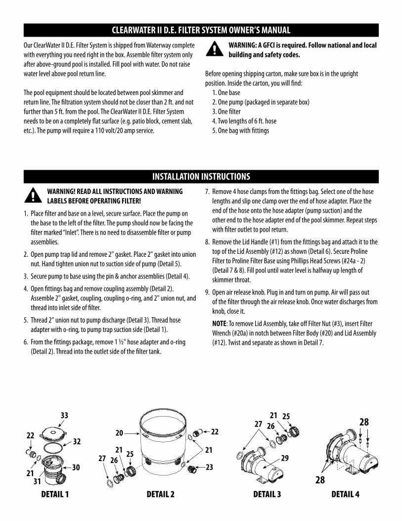
1. Place filter and base on a level, secure surface. Place the pump on the base to the left of the filter. The pump should now be facing the filter marked “Inlet”. There is no need to disassemble filter or pump assemblies.
2. Open pump trap lid and remove 2" gasket. Place 2" gasket into union nut. Hand tighten union nut to suction side of pump (Detail 5).
3. Secure pump to base using the pin & anchor assemblies (Detail 4).
4. Open fittings bag and remove coupling assembly (Detail 2). Assemble 2" gasket, coupling, coupling o-ring, and 2" union nut, and thread into inlet side of filter.
5. Thread 2" union nut to pump discharge (Detail 3). Thread hose adapter with o-ring, to pump trap suction side (Detail 1).
6. From the fittings package, remove 1 1/2" hose adapter and o-ring (Detail 2). Thread into the outlet side of the filter tank.
7. Remove 4 hose clamps from the fittings bag. Select one of the hose lengths and slip one clamp over the end of hose adapter. Place the end of the hose onto the hose adapter (pump suction) and the other end to the hose adapter end of the pool skimmer. Repeat steps with filter outlet to pool return.
8. Remove the Lid Handle (#1) from the fittings bag and attach it to the top of the Lid Assembly (#12) as shown (Detail 6). Secure Proline Filter to Proline Filter Base using Phillips Head Screws (#24a - 2) (Detail 7 & 8). Fill pool until water level is halfway up length of skimmer throat.
9. Open air release knob. Plug in and turn on pump. Air will pass out of the filter through the air release knob. Once water discharges from knob, close it.
NOTE: To remove Lid Assembly, take off Filter Nut (#3), insert Filter Wrench (#20a) in notch between Filter Body (#20) and Lid Assembly (#12). Twist and separate as shown in Detail 7.
CLEARWATER II D.E. FILTER SYSTEM OWNER’S MANUAL
INSTALLATION INSTRUCTIONS
33
32
30
3121
22
29
27 2621 25
DETAIL 1 DETAIL 3DETAIL 2
20
25212627
22
21
23
DETAIL 4
28
28

CLEARWATER II D.E. FILTER SYSTEM REPLACEMENT PARTSItem Part No. Description1 519-7601 Lid Handle2 819-9002 #12 x 3/4" S/S Phillips Head Screw3 718-7251 Filter Locknut Assembly4 602-0200 Air Relief Plug5 805-0207 O-Ring - Air Relief6 830-4000SS Pressure Gauge7 519-7451 Handle Assembly (2)8 805-0224 O-Ring - Air Relief9 519-7430 Gauge - Fitting Adapter10 805-0117SD O-Ring - Adapter11 805-0460 Lid O-Ring12 519-7411 Lid Assembly (Small) 519-7401 Lid Assembly (Large)13 519-7441 Wing-Nut14 500-7310 Screen/Sock Assembly15 718-7210 Tie Nut - D.E.16 519-7491 Sleeve - D.E.17 519-7269 Locator - Top Grids - D.E.18 550-7210 D.E. Grids - 12 sq. ft. (7) 550-7220 D.E. Grids - 18 sq. ft. (7)19 550-7100 Base Assembly - 12 sq. ft. 550-7120 Base Assembly - 18 sq. ft.20 515-7251 Filter Body Bottom20a 519-7470 Filter Wrench (see Detail 7)21 805-0224 O-Ring (4)22 417-6241 1 1/2" MPT x 1 1/2" Male Smooth Hose Adapter (2)23 500-5300 Drain Assembly24 672-7401 Proline Base24a 819-0044 #10 x 1" S/S Phillips Head Screw (2)25 415-5001 2" Union Nut26 419-7241 Coupling27 711-4010 2" Union Gasket (2)28 429-7221 Snap Pin (4)29 PH1100 1 HP - 1-Speed - Hi-Flo II Pump PH1150 1 1/2 HP - 1-Speed - Hi-Flo II Pump PH1200 2 HP - 1-Speed - Hi-Flo II Pump PH2100 1 HP - 2-Speed - Hi-Flo II Pump PH2150 1 1/2 HP - 2-Speed - Hi-Flo II Pump PH2200 2 HP - 2-Speed - Hi-Flo II Pump30 310-6500 6" Trap - 1 1/2" Buttress x 2" Flange31 319-3230 6" Basket Assembly32 805-0436 O-Ring33 319-3260 6" Trap Lid
3
77
11
1 2
45
68
9 10
12
13
1617
18
19
20
22
21
23
24
24a (2)
28
2928
30
3121
22
33
3227
2621 25
1415
DETAIL 6
DETAIL 5
1
2
22
2131
30
29
27
3233
DETAIL 7
3
12
20
24a
24a
20a
DETAIL 8
24a
MOTOR DOES NOT START: Make sure motor is plugged in. Circuit breaker in OFF position. Thermal Overload in tripped position. Wiring installation incorrect. Incorrect line voltage. Defective wiring.
THERMAL OVERLOAD TRIPS: Low voltage. Wiring installation incorrect. Dual voltage pumps mis-wired. Inadequate ventilation.
NO WATER FLOW: Obstruction of suction or return line. Clogged impeller. Suction system air leaks. Slice valve closed. Clogged hose fitting. Clogged basket. Dirty filter.
EXCESSIVE PUMP NOISE: Worn bearings. Suction line clogged. Pump incorrectly mounted. Hose fitting partially closed. Clogged trap basket.
INADEQUATE FILTERING: Inadequately cleaned system. Excessive dirt load. Chemical imbalance. Inadequate system pressure.
FILTER LEAKS: Dirty o-ring or gasket. Improperly seated o-ring or gasket. Missing o-ring or gasket. Filter nut installed improperly.
TROUBLESHOOTING
WARRANTYFor product registration visit: www.waterwayplastics.com.
For Warranty questions or claims please contact point of purchase.
810-0072-2N.0618©2018 Waterway Plastics
2200 East Sturgis Road, Oxnard CA 93030 • Phone 805.981.0262 • Fax 805.981.9403www.waterwayplastics.com • [email protected]
Designed,Engineered & Manufactured
in the USA.