Embed Size (px)
Citation preview

COPY NO: 22
DEVELOPMENT ENGINEERINGSPECIFICATIONS -
DESIGNSPECIFICATION
Date adopted by Council: 4 June 2001

TABLE OF CONTENTS
DO – DOCUMENTATION
D1 - GEOMETRIC ROAD DESIGN (URBAN AND RURAL)
D2 – PAVEMENT DESIGN
D3 – STRUCTURES/BRIDGE DESIGN
D4 – SUBSURFACE DRAINAGE DESIGN
D5 – STORMWATER DRAINAGE DESIGN
D6 – SITE REGRADING
D7 – EROSION CONTROL AND STORMWATER MANAGEMENT
D9 – CYCLEWAY AND PATHWAY DESIGN
D10 – BUSHFIRE PROTECTION

DEVELOPMENT DESIGNSPECIFICATION
DO
DOCUMENTATION
Revised June 2001

DOCUMENTATION
D.0 - 1 SINGLETON SHIRE COUNCIL
CONTENTS
D1 GEOMETRIC ROAD DESIGN (URBAN AND RURAL) 2
DO.01 PLAN REQUIREMENTS 2
D2 PAVEMENT DESIGN 3
DO.02 DESIGN CRITERIA AND CALCULATIONS 3
D4 SUBSURFACE DRAINAGE DESIGN 3
DO.03 DESIGN DRAWINGS AND CALCULATIONS 3
D5 STORMWATER DRAINAGE DESIGN 3
DO.04 PLANS 3
DO.05 EASEMENTS AND AGREEMENTS 4
DO.06 SUMMARY SHEETS 4
DO.07 COMPUTER PROGRAM FILES AND PROGRAM OUTPUT 4
D6 SITE REGRADING 4
DO.08 PLANS 4
DO.10 TOPSOIL 5
D9 CYCLEWAY AND PATHWAY 5
DO.11 PRESENTATION OF DESIGNS 5
D7 – EROSION CONTROL AND STORMWATER MANAGEMENT 6
DO.12 DETAILED DESIGN 6

DOCUMENTATION
Revised 7 January 2001 D.0 -2SINGLETON SHIRE COUNCIL
DOCUMENTATION
D1 GEOMETRIC ROAD DESIGN (URBAN AND RURAL)
GENERAL
Developers should engage the services of suitably qualified Geotechnical Engineers tocarry out investigations for pavement design subgrade evaluations.
DO.01 PLAN REQUIREMENTS
1.
(a) Reduction Ratios
All plans for urban design are to be reduced to 1:500. Rural designs may be reduced to1:1000.
Longitudinal Sections 1:500 H1:100 V
Cross Sections 1:100 Natural
(b) Plan Sheets
Separate sheets should be provided for
a. Cover sheetsb. Plan viewsc. Longitudinal sectionsd. Cross sectionse. Structural detailsf. Erosion & Sedimentation Controlg. Standard drawings
(c) Plan Presentation
Plans are to be presented on A1 sheets unless otherwise authorised. They are to be clearand legible and prepared in consistent lettering and style. Council has the authority torefuse plans that do not meet these drafting requirements. Plans copied from other workswill not be accepted. All plans shall be clearly referenced with notations and tables asappropriate. The designer should always be mindful that apart from being a permanentrecord and legal document, plans should be easily read and understood by the Contractor,and others involved in the construction of the works. Terminology should be kept in 'plainenglish' where possible.
PermanentRecord
2. Work as Executed plans shall be submitted to Council upon completion of the roadconstruction and prior to release of the linen plan. The detailed design plans may form thebasis of this information, however, any changes must be noted on these plans. TheContractor shall supply plans in electronic format to Council upon completion.
W.A.E.
3. Cross Section spacings shall be 10m for kerb and gutter and 20m for roads.Additional cross sections are required at high points, low points, S S, T S, T P and S C.
Spacings

DOCUMENTATION
Revised 7 January 2001 D.0 -3SINGLETON SHIRE COUNCIL
D2 PAVEMENT DESIGN
DO.02 DESIGN CRITERIA AND CALCULATIONS
1. All considerations, assumptions, subgrade test results, and calculations shall besubmitted with the pavement design for approval by Council.
SubmissionDetails
2. The Drawings shall clearly indi cate the structure, material types and layerthicknesses of the proposed pavement and surfacing. Drawings
3. Work as Executed plans shall be submitted to Council upon completion of thepavement construction and prior to release of the linen plan. The detailed designplans may form the basis of this information, however, any changes must be notedon these plans. The Contractor shall supply plans in electronic format to Councilupon completion.
D4 SUBSURFACE DRAINAGE DESIGN
DO.03 DESIGN DRAWINGS AND CALCULATIONS
1. The proposed location of all subsurface drains shall be clearly indicated on theDesign Drawings, including the nominal depth and width of the trench, and the location withrespect to the line of the kerb/gutter or edge of pavement. Where practicable, the locationof outlets and cleanouts shall also be indicated on the Drawings.
2. Assumptions and/or calculations made in the determination of the need orotherwise for subsurface drainage in special circumstances or as a variation to therequirements of this specification shall be submitted to Council for approval with the DesignDrawings.
D5 STORMWATER DRAINAGE DESIGN
DO.04 PLANS
1. Catchment Area Plans shall be drawn at scales of 1:500, 1:4000 or 1:25000,unless alternative scales are specifically approved by Council and shall show contours,direction of grading of kerb and gutter, general layout of the drainage system with pitlocations, catchment limits and any other information necessary for the design of thedrainage system.
Scales forDrawings
2. The Drainage System Layout Plan shall be drawn at a scale of 1:500 and shallshow drainage pipeline location, drainage pit location and number and road centrelinechainage, size of opening and any other information necessary for the design andconstruction of the drainage system.
3. The plan shall also show all drainage easements, reserves and natural watercourses.
4. The Drainage System Longitudinal Section shall be drawn at a scale of 1:500horizontally and 1:50 vertically and shall show pipe size, class and type, jointing type,pipeline and road chainages, pipeline grade, hydraulic grade line and any other information

DOCUMENTATION
Revised 7 January 2001 D.0 -4SINGLETON SHIRE COUNCIL
necessary for the design and construction of the drainage system.
5. Open Channel Cross Sections shall be drawn at a scale of 1:100 natural and shallshow the direction in which the cross sections should be viewed. Reduced levels are to beat Australian Height Datum, AHD, unless otherwise approved by Council where AHD is notavailable. Cross sections may alternatively be provided on floppy disk in HEC2 format as adata input file for the design flow rates.
OpenChannels
6. Special Details including non-standard pits, pit benching, open channel designs,culverts and transitions shall be provided on the design drawings at scales appropriate tothe type and complexity of the detail being shown.
7. Work as Executed Plans shall be submitted to Council upon completion of thedrainage construction and prior to release of the linen plan. The detailed design plans mayform the basis of this information, however, any changes must be noted on these plans.The Contractor shall supply plans in electronic format to Council upon completion.
Work-as-ExecutedPlans
DO.05 EASEMENTS AND AGREEMENTS
1. Evidence of any Deed of A greement necessary to be entered into as part of thedrainage system will need to be submitted prior to any approval of the engineering plans.Easements will need to be created prior to approval of the linen plan of subdivision.
2. Where an agreement is reached with an adjacent landowner to increase floodlevels on his property or otherwise adversely affect his property, a letter signed by all thelandowners outlining what they have agreed to and witnessed by an independent personshall be submitted prior to any approval of the engineering plans.
DO.06 SUMMARY SHEETS
1. A copy of a Hydrological Summary Sheet providing the minimum information setout in AR&R 1987.
Hydrology
2. A copy of a Hydraulic Summary Sheet providing the minimum information set out inAR &R 1987.
Hydraulics
DO.07 COMPUTER PROGRAM FILES AND PROGRAM OUTPUT
1. Computer program output may be provided as long as summary sheets forHydrological and Hydraulic calculations in accordance with this Specification are providedwith plans submitted for checking and with final drawings.
2. Copies of final computer data files, for both hydrological and hydraulic models shallbe provided for Council's data base of flooding and drainage information in formatspreviously agreed with Council.
D6 SITE REGRADING
DO.08 PLANS
1. Load limits and location of haul roads are to be shown on the Site Regrading Plan.The Consultant shall refer to Council for acceptable haul roads with applicable load limits.
Load Limits onhaul roads

DOCUMENTATION
Revised 7 January 2001 D.0 -5SINGLETON SHIRE COUNCIL
2. The payment of a Bond may be required by the developer/contractor whereCouncil has some concern about the ability of a haul road to sustain the loads withoutundue damage or maintenance requirements.
Possible BondRequirement
3. The site regrading plans shall show extent and depth of the site regrading Extent/Depth
DO.09 PERMIT TO ENTER TO DISCHARGE STORMWATER/CONSTRUCT
1. Where it is proposed to divert, direct or intensify the flow of stormwater intoadjoining property, a "permit to discharge stormwater shall be sought and submitted toCouncil prior to the approval of Engineering design plans." The above shall apply unlessotherwise specified by Council. A permit shall also be sought to carry out construction workon adjoining property and such permit also presented to Council.
PermitRequired
DO.10 TOPSOIL
1. Unless specific application is made to Council and approval obtained, the plans willbe annotated as follows:
"All topsoil shall be retained on the development site and utilised effectively toencourage appropriate revegetation."
Topsoil
D9 CYCLEWAY AND PATHWAY
DO.11 PRESENTATION OF DESIGNS
1. The following listing outlines Council's minimum requirements for presentation ofcycleway and/or pathway designs.
• All plans for cycleways/pathways are to be presented at the reduction ratio 1:500. Plans
• The cycleway plan sheet may be incorporated into the road plan where claritypermits. Specific details are to be provided at reduction ratio 1:200.
• Longitudinal Sections will be required for all of f-road cycleways where gradesexceed 4%.
Long Sections
• Longitudinal Sections will have reduction ratios of 1:500 horizontal and 1:100vertical.
• Cross Sections will be presented at 1:100 reduction ratio (natural) and transitiontables will be required where cross falls vary or superelevation is provided.
Cross Sections
• A typical cross section will be detailed to indicate pavement materials and layerdepths.
2. Work as Executed plans shall be submitted to Council upon completion of thecycleway or pathway construction and prior to release of the linen plan. Thedetailed design plans may form the basis of this information, however, anychanges must be noted on these plans. The Contractor shall supply plans inelectronic format to Council upon completion.

DOCUMENTATION
D.0 -6SINGLETON SHIRE COUNCIL
D7 – EROSION CONTROL AND STORMWATER MANAGEMENT
DO.12 DETAILED DESIGN
1. Detailed designs shall include scaled drawings (no larger than 1:1000) and detailedspecifications/diagrams which can be readily understood and applied on site by supervisorystaff.
Items to be included, but not limited to, shall be:
• existing and final contours
• the location of all earthworks including roads, areas of cut and fill and re-grading
• location of access haulage tracks and borrow pits
• location and design criteria of erosion and sediment control structures
• location and description of existing vegetation
• proposed vegetated buffer strips and "no access" areas
• location of critical areas (vegetated buffer strips, drainage lines and structures,water bodies, unstable slopes, flood plains and seasonally wet areas)
• type and location of diversion works to direct uncontaminated water aroundareas to be disturbed
• stockpile sites and treatment thereof
• revegetation program
• procedures for maintenance of erosion and sediment control both during andafter construction, until end of Defects Liability Period.
• details for staging of works

DEVELOPMENT DESIGNSPECIFICATION
D1Modified 3
GEOMETRIC ROAD DESIGN(Urban and Rural)
Revised June 2001

GEOMETRIC ROAD DESIGN
Revised 17 March 2000 D1-1 SINGLETON SHIRE COUNCIL
CONTENTS
CLAUSE PAGE
GENERAL 3
D1.01 SCOPE................................................................................................................................. 3
D1.02 AIMS..................................................................................................................................... 3
D1.03 REFERENCE AND SOURCE DOCUMENTS ......................................................................... 3
D1.04 CONSULTATION .................................................................................................................. 4
D1.05 PLANNING CONCEPTS ....................................................................................................... 4
D1.06 WITHDRAWN ....................................................................................................................... 4
URBAN DESIGN CRITERIA 5
D1.07 ROAD HIERARCHY.............................................................................................................. 5
D1.08 ROAD NETWORK................................................................................................................. 6
D1.09 DESIGN SPEED ................................................................................................................... 7
D1.10 LONGITUDINAL GRADIENT................................................................................................. 7
D1.11 HORIZONTAL CURVES AND TURNING MOVEMENTS ........................................................ 8
D1.12 VERTICAL CURVES............................................................................................................. 8
D1.13 SUPERELEVATION.............................................................................................................. 8
D1.14 CARRIAGEWAY WIDTH....................................................................................................... 9
D1.15 CROSSFALLS .................................................................................................................... 10
D1.16 FOOTWAY AREAS............................................................................................................. 10
D1.17 INTERSECTIONS, TURNING MOVEMENTS AND CUL-DE-SACS....................................... 10
D1.18 ROUNDABOUTS ................................................................................................................ 11
D1.19 TRAFFIC CALMING............................................................................................................ 12
D1.20 PARKING ........................................................................................................................... 12
D1.21 BUS ROUTES..................................................................................................................... 12
RURAL DESIGN CRITERIA 13
D1.22 GENERAL........................................................................................................................... 13
D1.23 SIGHT DISTANCES............................................................................................................ 13
GEOMETRIC ROAD DESIGN
Revised 17 March 2000 D1-2 SINGLETON SHIRE COUNCIL
D1.24 HORIZONTAL AND VERTICAL ALIGNMENT ...................................................................... 13
D1.25 INTERSECTIONS ............................................................................................................... 13
D1.26 PLAN & SUPERELEVATION TRANSITIONS....................................................................... 13
D1.27 CARRIAGEWAYS............................................................................................................... 15
D1.28 DESIGN SPEED ................................................................................................................. 15
D1.29 SCOUR PROTECTION ....................................................................................................... 16
D1.30 ROAD HIERARCHY............................................................................................................ 16
SPECIAL REQUIREMENTS 17
D1.31 URBAN PRIVATE RIGHT OF WAY’S .................................................................................. 17
D1.32 RESERVED........................................................................................................................ 17
D1.33 RESERVED........................................................................................................................ 17

GEOMETRIC ROAD DESIGN
Revised 17 March 2000 D1-3 SINGLETON SHIRE COUNCIL
DEVELOPMENT DESIGN SPECIFICATION D1 -DESIGN (Urban and Rural)
GENERAL
D1.01 SCOPE
1. This section sets out design specifications to be used in the subdivision ofland.
2. All relevant design principles must be integrated in the development of theroad network. A careful balance is required between maximising amenity,safety considerations and those related to legibility and convenience.
D1.02 AIMS
1. The provision of a road system within a subdivision is to be designed soas to achieve the following aims:
� Provide convenient and safe access to all allotments forpedestrians, the disabled, vehicles and cyclists.
� Provide safe, logical and hierarchical transport linkages withexisting street system.
� Provide appropriate access for buses, emergency and servicevehicles.
� Provide for a quality product that minimises maintenance costs.
� Provide a convenient way for public utilities.
� Provide an opportunity for street landscaping.
� Provide convenient parking for visitors.
� Have appropriate regard for the climate, geology andtopography of the area.
D1.03 REFERENCE AND SOURCE DOCUMENTS
(a) Council Specifications
All Specifications for Design and Construction.
Singleton Shire Council Road Management Strategy – Road Hierarchy
(b) Australian Standards
AS 2890.1 Parking facilities: Off-street car parking.
AS2890.2 Off Street Parking – Commercial Vehicle Facilities
(c) State Authorities
Roads and Traffic Authority NSW - Road Design Guide.Department of Housing - Road Manual, 1987.Department of Urban Affairs (formerly Environment) and Planning –
Technical Bulletin 12 (1981), Residential RoadWidths.
(d) Other
AUSTROADS Guide to the Geometric Design of Rural Roads.Guide Policy for the Geometric Design of Major Urban
Roads.Guide to Traffic Engineering Practice:

GEOMETRIC ROAD DESIGN
Revised 17 March 2000 D1-4 SINGLETON SHIRE COUNCIL
PART 5, Intersections at GradePART 6, RoundaboutsPART 10, Local Area Traffic ManagementPART 13, PedestriansPART 14, Bicycles
The Institute of Municipal Engineering Australia, Qld Division - 1993: DesignGuidelines for Subdivisional Streetworks.
ARRB Special Report No. 33, L E Comerford: A Review of Subdivision RoadDesign Criteria.
Joint Venture for More Affordable Housing - 1989: Australian Model Code forResidential Development.
Stapleton, C 1984: Streets Where We Live - A Manual for the Design of SaferResidential Estates.
Stapleton, C 1988, Dept of Transport South Australia: Planning & Road Designfor New Residential Subdivisions.
Brindle, R 1988, ARRB: Planning & Design of the Local Distributor.
Colman, J 1978, ARRB: Streets for Living.
Pak-Poy Kneebone - 1989: Research Study into Road Characteristics forResidential Development.
D1.04 CONSULTATION
1. Designers are encouraged to consult with Singleton Shire Council andother relevant authorities prior to or during the preparation of design. Designersshould in addition to requirements of this Specification ascertain Singleton ShireCouncil’s specific requirements as they relate to the designs in hand.
D1.05 PLANNING CONCEPTS
1. In new areas (as distinct from established areas with a pre-existing roadpattern) each class of route should reflect its role in the road hierarchy by its visualappearance and related physical design standards. Routes should differ inalignment and design standard according to the volume of traffic they are intendedto carry, the desirable traffic speed, and other factors.
RoadHierarchy
2. The road pattern and width must be in conformity with that shown on anyrelevant area Development Control Plan. In areas not covered by these plans,Council will determine the pattern and width(s) on their merits.
3. The road network for residential developments should have clear legibility.
4. The road network should reinforce legibility by providing sufficientdifferentiation between the road functions.
5. Wherever possible distinct landmark features such as watercourses,mature vegetation or ridge lines should be emphasised within the structural layoutso as to enhance the legibility.
Legibility
6. Whilst legibility can be enhanced by introduced physical features such aspavement and lighting details, the road network should by its inherent design andfunctional distinction provide the necessary legibility.
7. The maximum number of turning movements at intersections or junctionsthat a visitor should be required to undertake to reach a particular address withinthe development should be minimised.
D1.06 WITHDRAWN

GEOMETRIC ROAD DESIGN
Revised 17 March 2000 D1-5SINGLETON SHIRE COUNCIL
URBAN DESIGN CRITERIA
D1.07 ROAD HIERARCHY
1. A hierarchical road network is essential to maximise road safety,residential amenity and legibility. Each class of road in the network serves adistinct set of functions and is designed accordingly. The design should conveyto motorists the predominant function of the road. For information on all theexisting urban roads and streets that are maintained by council refer toSingleton Shire Council “Roads Management Strategy”.
Urban Hierarchy Classes and Parameters
Class Description Design Considerations
Urban ArterialPrimarily carry throughtraffic from one region toanother.
Direct access for single dwelling allotments isnot permitted. Access to multi-unitdevelopments and non-residential land usesare also not permitted.
Urban Sub-Arterial
Connect the arterial roadsto areas of development orcarry traffic directly fromone part of a region toanother.
Direct accss for single dwelling allotments isto be discouraged. Access may be provided tomulti-unit developments and non-residentialland uses (at the discretion of Council).
Urban CollectorConnect the sub-arterialroads to the local roadsystem in developed areas.
This class of streets have a residentialfunction but they also carry a higher volume oftraffic collected from local streets. Areasonable level of residential amenity andsafety is maintained by restricting trafficvolumes and speeds. However, amenity &resident safety do not have as high a priorityas local streets.
Urban Local 1
Local roads that allowthrough traffic and primarilyprovide access toresidential properties andpossibly some minorcommercial development.
Streets in this class should provide a balancebetween the status of that street in terms of itsaccess and residential amenity functions.Resident safety and amenity are dominant butto a lesser degree than Urban Local 2 roads.However, they should have features which aidpedestrian and cycle movements.
Urban Local 2
No through roads thatprovide access toresidential properties (ie,cul-de-sacs).
The prime consideration with this class ofroad is to ensure residential space andamenity. They should have features which aidpedestrian and cycle movements. Motorisedtraffic is subservient in terms of speed andvolume, to those elements of space, amenity,pedestrians and cyclists.
LanewayRoads that primarilyprovide rear access tovarious land uses.
The main consideration with laneways is toensure that the type of vehicle that will accessthe specific land uses can do so safely. Stepsshould be taken to minimise traffic speed.

GEOMETRIC ROAD DESIGN
Revised 17 March 2000 D1-6SINGLETON SHIRE COUNCIL
For example, a graphical depiction of Singleton Shire Council’s Urban Road Hierarchy is given below:
D1.08 ROAD NETWORK
1. The design features of each type of road convey to the motorist itsprimary functions and encourage appropriate driver behaviour.
2. Traffic volumes and speeds on any road should be compatible with theresidential functions of that road.
3. The maximum length of a local street and laneway should ensure itsstatus as a residential place is retained, where the traffic, in terms of speed andvolume will enable the integration of pedestrian, cycle and vehicular movements.This length will also ensure that residential convenience is not unduly impairedas a result of speed restraints.
4. The time required for motorists to travel on all streets within thedevelopment should be minimised.
5. Where local streets form part of a pe destrian or cycle network, accesslinks should provide suitable connectivity with adjoining local streets or openspace systems so as to ensure such pedestrian and cycle network arefunctionally efficient.
6. The road network should ensure that no road l inks with another roadwhich is more than two levels higher or lower in the hierarchy.
Road Links
UrbanLocal 2
UrbanLocal 1
Laneway
Urban Road Hierarchy for New Urban Subdivisions
Urban Collector
Urban Sub-Arterial
Urban Arterial

GEOMETRIC ROAD DESIGN
Revised 17 March 2000 D1-7SINGLETON SHIRE COUNCIL
7. Connections between internal roads should be T-junctions or controlledby roundabouts.
8. The road layout should conform to the requirements of the ex ternal roadnetwork and satisfy the transport provisions of an outline development plan.
9. The external road network should be designed and located to provideroutes which are more convenient for potential through local road network.Major roads should be provided at intervals of no more than 1.5 km and shouldbe complete and of adequate capacity to accommodate projected movements.The internal road system should not provide through routes that are moreconvenient than the external road network.
ExternalRoadNetwork
10. Where approved, cul-de-sacs longer than 150m shall be designed toUrban Local 1 Criteria.
D1.09 DESIGN SPEED
1. Design speed is generally used as the basic parameter in thespecification of design standards, determining the minimum design value forother elements. The NSW Roads and Traffic Authority bases its current designstandards on a travel speed rather than a design speed. Travel speed identifiesa speed/horizontal radius relationship. This approach is intended for roads of aminimum travel speed of 60 km/h. The maximum speed limit in NSW for built-upareas is 60 km/h and this should be used in calculating design values whichdepend on speed, (eg collector and distributor roads) however, in difficulttopography, the design speed may be reduced. Vehicular speeds are alsolimited by road intersections as well as changes in horizontal and verticalalignment.
RTAGuidelines
2. Adoption of a low design speed discourages speeding, however, wherevertical or horizontal curves of low design speed are located in otherwise highspeed sections (tangents) the result is a potentially dangerous section of road. Itshould be recognised that in low standard roads, operating speeds will tend to bein excess of arbitrary speed standards. It must be ensured that potentiallyhazardous features are visible to the driver and adopting traffic engineeringmeasures which will help a driver avoid errors of judgement.
Low Speeds
3. Generally the following minimum design speeds should be adopted:Urban Local 2 & Laneways 60 km/hUrban Local 1 60 km/hUrban Collector 70 km/hUrban Sub Arterial & Arterial 80 km/h
D1.10 LONGITUDINAL GRADIENT
1. A general minimum gradient of 0.5% should be adopted. Maximumrecommended grades are shown in Table D1.1
Flat Terrain
Table D1.1
Laneways Urban Local 1&Urban Local 2
Urban Collector &Urban Sub - Arterial
Urban Arterial
Desirable maximum percentage 12 10 8 6
Absolute maximumpercentage*
14 12 10 8
* maximum length of a longitudinal grade <= the absolute maximum percentage and > the desirable maximumpercentage shall be 75m.
GEOMETRIC ROAD DESIGN
Revised 17 March 2000 D1-8SINGLETON SHIRE COUNCIL
2. Longitudinal grade through intersections should not exceed 4 per cent,the actual gradient being dependent on the type of terrain. Design of the roadalignment and the grades used are interrelated. A steep grade on a side street isundesirable if vehicles have to stand waiting for traffic in the priority road.Turning circles in cul-de-sacs on steep grades should have grades less than 5%.
Intersection
D1.11 HORIZONTAL CURVES AND TURNING MOVEMENTS
1. The Horizontal Curves and turning movements should conform with RTARoad Design Guide.
TransitionCurves
D1.12 VERTICAL CURVES
1. Vertical curves will be simple parabolas and should be used on allchanges of grade exceeding 1 per cent. The desirable minimum design speed is60 km/h. The length of the crest vertical curve for stopping sight distance shouldconform with RTA Road Design Guide. These standards are based on 1.5seconds reaction time which provides a reasonable safety margin for urbanconditions, where drivers' reaction time is usually considered to be lower than inrural conditions.
2. For adequate riding comfort, lengths of sag vertical curves shouldconform with the RTA Road Design Guide. As residential roads are usually lit atnight, the criterion for designing sag vertical curves is a vertical acceleration of0.05 g for desirable riding comfort, and 0.10 g for minimum riding comfort.
RidingComfort
3. Junctions of roads should be located at a safe distance from a crest,determined by visibility from the side road. Careful consideration shall be givenin the location of a side road at a crest. Refer to the RTA Road Design Guide forsite distances.
Side Road
4. Drainage poses a practical limit to the length of s ag curves and amaximum length (in metres) of 15 times the algebraic sum of the intersectingvertical grades (expressed as a percentage) has been suggested. This is toavoid water ponding in excessively flat sections of kerb and gutter. A minimumgrade of 0.5 per cent should be maintained in the kerb and gutter. This mayrequire some warping of road cross sections at sag points.
Sag Curves
5. The three dimensional coordination of the horizontal and verticalalignment of a road should be aimed at improved traffic safety and aesthetics.Economic considerations often require a compromise with aestheticconsiderations. The design speed of the road in both horizontal and verticalplanes should be of the same order.
D1.13 SUPERELEVATION
1. The use of su perelevation in association with horizontal curves is anessential aspect of geometric design of roads with design speeds in excess of 60km/h.
2. The maximum superelevation for urban roads of higher design speedsshould be 5 per cent. Any increase in the longitudinal grade leading to excessivecrossfall at intersections should be considered with caution. While it is desirableto superelevate all curves, negative crossfall should be limited to 3 per cent.
NegativeCrossfall
3. In general, curve radii larger than the minimum and superelevation ratesless than the maximum should be used where possible.
Coefficientof SideFriction
4. Recommendations for minimum curve radii (in metres) on major urbanroads under varying superelevation/crossfall are shown in Table D1.4.

GEOMETRIC ROAD DESIGN
Revised 17 March 2000 D1-9SINGLETON SHIRE COUNCIL
Tables D1.2, D1.3 WITHDRAWN
Table D1.4
Design Speed km/h
60 70 80Minimum Superelevation
(%)Minimum curve radii (metres)
54321
145150160170180
195205215230245
255265280300315
Design Speed km/h
60 70 80
Maximum Crossfall
(%)
Minimum curve radii (metres)
0123
190260285315
260355390430
340460505560
(Source: NAASRA (Now AUSTROADS), Guide policy for the geometric design of major urban roads.)
5. Plan transitions are desirable on superelevated cur ves forappearance and to provide a convenient length in which to apply thesuperelevation. On urban roads, superelevation may be convenientlyapplied to the road cross section by shifting the crown to 2m from the outerkerb. The axis of rotation of the cross section for urban roads will normallybe the kerb grading on either side which best enables access to adjacentproperties and intersections. On the outside of superelevation, or where thelongitudinal grade of the gutter is less than 0.5 per cent, a crossfall of 63mmin a 450mm wide gutter may be adopted.
Offset Crown
D1.14 CARRIAGEWAY WIDTH
1. The cross section of the road reserve must cater for all functionsthat the road is expected to fulfil, including the safe and efficient movementof all users, provision for parked vehicles, acting as a buffer from trafficnuisance for residents, the provision of public utilities and streetscaping.Refer to Table D1-5 for carriageways, footway widths and road reservewidths.
Functions
Table D1.5
Urban Hierarchy Class Road ReserveWidth *(m)
MaximumTraffic Volume
(vpd)
MinimumCarriagewayWidth (m)**
Minimum verge/ footway width -
each side (m)Urban Local 2 18 100 9.0 4.0Urban Local 1 20 2,000 11.0 4.0Urban Collector 25 3,000 13.0 4.0Urban Sub- Arterial &Urban Arterial
25 6,000 13.0 4.0
* Road Reserve width includes footpath/cycleway and kerb requirements** Carriageway width includes the provision for parallel parking for both sides of carriageway

GEOMETRIC ROAD DESIGN
Revised 17 March 2000 D1-10SINGLETON SHIRE COUNCIL
D1.15 CROSSFALLS
1. For typical pavement crossfalls refer to Austroads Guide policy forgeometric design of major urban roads.
2. The crossfall on a collector or distributor road should takeprecedence over the grade in side streets. Standard practice is to maintainthe crossfall on the priority road and adjust the side road levels to suit. Thecrossfall in side streets should be warped quickly either to a crown or auniform crossfall depending on the configuration of the side street. A rate ofchange of grade of two per cent in the kerb line of the side street relative tothe centre line grading is a reasonable level.
Priority Road
D1.16 FOOTWAY AREAS
1. A suitable design for the footway will depend on utility services, thewidth of pathways, access to adjoining properties, likely pedestrian usageand preservation of trees. Low level paths are undesirable but may be usedif normal crossfalls are impracticable. Crossfalls in footway paving shouldnot exceed 4 per cent, as above this paving can be slippery. Longitudinalgrade usually parallels that of the road and this may be steeper than 5 percent. Refer to Section D.9 – Cycleways & Pathways Design.
UtilityServices
D1.17 INTERSECTIONS, TURNING MOVEMENTS AND CUL-DE-SACS
1. The design of intersections or junctions should allow all move mentsto occur safely without undue delay. Projected traffic volumes should beused in designing all intersections.
TrafficVolumes
2. The design for all intersections should be designed in accordancewith the publication AUSTROADS Guide to Traffic Engineering Practice,PART 5, Intersections at Grade.
Main Roads
3. Intersections with classified roads are to be designed andconstructed in accordance with the requirements of the Roads and TrafficAuthority.
ClassifiedRoads
4. Where intersections are required to serve a development, completereconstruction of the existing road pavements will be necessary where thespeed environment and/ or irregularity of the existing road pavementrequires reconstruction to be undertaken.
5. Intersections should be generally located in such a way that:� The streets intersect preferably at right-angles and not lessthan 70°.� The landform allows clear sight distance on each of theapproach legs of the intersection.� The minor street intersects the convex side of the majorstreet.� The vertical grade l ines at the intersection do not imposeundue driving difficulties.� The vertical grade lines at the intersection will allow for anydirect surface drainage.� Two side streets intersecting a major street in a staggeredpattern should have a minimum centre-line spacing of 40 m.
Criteria
6. Sight distances as outlined in Section 2 of the RTA “Road DesignGuide” are to be provided for horizontal and vertical curves at allintersections.

GEOMETRIC ROAD DESIGN
Revised 17 March 2000 D1-11SINGLETON SHIRE COUNCIL
7. Where required, appropriate provision should be made for vehiclesto park safely.
8. In cul-de-sac streets (Urban Local 2 Streets) adequate provisionshould be made at the end of the road for vehicle types which frequently usethe streets to turn around.
9. The drainage function of the carriageway and/or road reserve mustbe satisfied by the road reserve cross-section profile.
10. All vehicle turning movements are accommodated utilisingAUSTROADS Design Vehicles and Turning Templates, as follows:
� For turning movements involving Urban Sub-Arterial Streets, the"design semi-trailer" with turning path radius 15.0 m.
� For turning movements involving Urban Collector or Urban Local 1streets, but not Urban Sub-Arterial Streets, the "design single unit"bus with turning path radius 15.0 m.
� For turning movements on laneways but not involving UrbanCollector, Urban Local 1 streets or Urban Sub-Arterial Streets, thegarbage collection vehicle used by the local authority.
� For turning movements at the head of Urban Local 2 streetssufficient area is provided for the "design single unit" truck to make athree-point turn or where the length of the street is less than 60.0mfor the "design car" to make a three-point turn.
TurningMovements
11. Turning radii at intersections or driveways on arterial or sub arterialroads shall be designed to accommodate the intended movements withoutallowing desired speeds to be exceeded.
Turning Radii
12. On bus routes 3-centred curves with radii 7.0 m, 10.0 m, 7.0 m areused at junctions and intersections.
Bus Routes
13. Combined entry and exit dri veways on urban sub-arterial roads are6.0 m wide and separate entry and exit driveways are 3.0 m wide.
D1.18 ROUNDABOUTS
1. Roundabouts are to be approved by the Council and/or the Roads& Traffic Authority.
2. Roundabouts should generally be design ed in accordance with therequirements of the publication AUSTROADS Guide to Traffic EngineeringPractice - PART 6 Roundabouts and RTA document “RoundaboutsGeometric Design Method” Designs adopting alternative criteria will beconsidered on their merits. Roundabout design should generally complywith the following:
• entry width to provide adequate capacity
• adequate circulation width, compatible with the entry widths anddesign vehicles e.g. buses, trucks, cars.
• central islands of diameter sufficient only to give drivers guidance onthe manoeuvres expected
• deflection of the traffic to the left on entry to promote gyratorymovement
• adequate deflection of crossing movements to ensure low trafficspeeds
• a simple, clear and conspicuous layout
• design to ensure that the speed of all vehicles approaching theintersection will be less than 50 km/h.

GEOMETRIC ROAD DESIGN
Revised 17 March 2000 D1-12SINGLETON SHIRE COUNCIL
D1.19 TRAFFIC CALMING
Speed reduction can be achieved by:
• creating a visual environment conducive to lower speeds. This can beachieved by 'segmenting' streets into relatively short lengths (less than300m), using appropriate devices, streetscapes, or street alignment tocreate short sight lines
• using devices which shift vehicle paths laterally (roundabouts, corners)
D1.20 PARKING
1. The parking requirements for normal levels of activity associatedwith any land use as specified in the RTA’s “Guide to Traffic GeneratingDevelopments” are to be provided on-site.
2. All on-site parking should be located and of dimensions that allowconvenient and safe access and usage.
3. The availability of parking should be adequate to minimise thepossibility of driveway access being obstructed by cars parked on theopposite side of the street.
4. Parking spaces provided on the verge or carriageway should be ofadequate dimensions, convenient and provide safe to access.
5. For non-residential land uses the opportunity for joint use of parkingshould be maximised by being shared by a number of complementing uses.
Joint Use
6. A single (car) space is 6.5m x 2.5m and combined spaces are13.0m x 2.5m (for two cars) and 20m x 2.5m (for truck parking) withadequate tapers at both ends to allow the necessary parking manoeuvresdetermined by using AUSTROADS Turning Templates.
Tandem
7. All verge spaces and indented parking areas a re constructed ofconcrete, interlocking pavers, lawn pavers, bitumen with crushed rock orother suitable material and are designed to withstand the loads andmanoeuvring stresses of vehicles expected to use those spaces.
Verge Spaces
8. The layout and ac cess arrangements for parking areas for non-residential land uses should conform to Australian Standard 2890.1 and2890.2.
D1.21 BUS ROUTES
1. Bus routes will normally be identified by Council. It is important thatthe road hierarchy adequately caters for buses.
Buses
Tables D1.6,D1.7 deleted

GEOMETRIC ROAD DESIGN
Revised 17 March 2000 D1-13 SINGLETON SHIRE COUNCIL
RURAL DESIGN CRITERIA
D1.22 GENERAL
1. In addition to the foregoing sections this section specifically applies toall those sites identified as being suited to rural subdivisions inclusive of ruralhomesites and hobby farms types of developments.
2. Design speed is to be generally used as the basic parameter of designstandards and the determination of the minimum design value for otherelements in rural subdivisions is to be based on the concept of a "speedenvironment" as outlined in RTA Road Design Guide.
Design Speed
3. Where appropriate superelevation, widening and centreline shift andtheir associated transitions are to comply with the RTA Road Design Guide.
4. Where the table drain is likely to s cour a RTA Type SH dish drain, orsimilar structure is to be constructed along the invert. Also for grades of lessthan 0.5%, the table drains are to be designed to prevent siltation.
Table Drain
5. Generally, rural subdivisions should be designed to de ny access to theexisting road network from the lots created within the subdivision. Lots shouldgain access to the internal subdivision road.
6. Access should be limited to one point on to local or arterial roadnetworks.
Access
D1.23 SIGHT DISTANCES
1. Recommended sight distances are given in the RTA Road DesignGuide.
D1.24 HORIZONTAL AND VERTICAL ALIGNMENT
1. Horizontal and vertical curves are to be designed generally to therequirements of RTA Road Design Guide. These requirements are essential tosatisfy the safety and performance of proper road design. Roads having bothhorizontal and vertical curvature should be designed to conform with the terrainto achieve desirable aesthetic quality and being in harmony with the landform.
D1.25 INTERSECTIONS
1. Intersections should generally be designed in accordance with thepublication AUSTROADS Guide to Traffic Engineering Practice - Part 5,Intersections at Grade. The type of intersection required will depend onexisting and planned connecting roads. Consideration should be given to leftturn treatments, deceleration and acceleration lands.
2. An absolute minimum spacing of 40m should be adopted for staggeredjunctions. The intersection angle between two roads should preferably be 90 °,and variations to this should be within +/- 20° band.
StaggeredJunctions
D1.26 PLAN & SUPERELEVATION TRANSITIONS
1. A plan transition is the length over which widening and shift isdeveloped to provide a natural path for vehicles entering a horizontal curve.Widening on horizontal curves compensates for differential tracking of front and

GEOMETRIC ROAD DESIGN
Revised 17 March 2000 D1-14 SINGLETON SHIRE COUNCIL
rear wheels of vehicles, and overhang of vehicles.
A super-elevation transition is the length over which normal road cross-fall isdeveloped up to full superelevation. This transition provides for comfortabletravel between the straight alignment of a road and the horizontal curve andavoids abrupt changes in cross-fall.
2. Abrupt changes in crossfall, can cause discomfort in travel and createa visible kink in the pavement. A rate of change of superelevation of no morethan 0.5 per cent relative to the centre line should ensure against this. Thewider the pavement the longer the transition. Superelevation transitions shouldbe used at all changes in crossfall, not just for curves.
CrossfallChanges

GEOMETRIC ROAD DESIGN
Revised 17 March 2000 D1-15 SINGLETON SHIRE COUNCIL
D1.27 CARRIAGEWAYS
The minimum carriageway widths for rural roads are detailed in Table D1.8
Table D1.8
Road Type Road ReserveWidth
Seal Width Formation Width TrafficLanes
Shoulders
Rural SubArterial
25m 8.5m 10m (+1.5m table drains& verges if needed
2x3.5m 2x1.5m (0.75m sealon each shoulder
RuralCollector
20m 8.0m 9m (+1.5m table drains &verges if needed
2x3.5m 2x1m (0.5m seal oneach shoulder)
Rural Local 1 20m 7m 8m (+1.5m table drains &verges if needed
2x3m 2x1m (0.5m seal oneach shoulder)
Rural Local 2 20m 7m 8m (+1.5m table drains &verges if needed
2x3m 2x1m (0.5m seal oneach shoulder)
Rural Local 3 20m 4m 5m (+1.5m table drains &verges if needed
2x3m 2x1m (0.5m seal oneach shoulder)
D1.28 DESIGN SPEED
Superelevation
Reference should be made to RTA Road Design Guide for superelevationcalculation.
Calculation
Longitudinal Gradient
The values listed in Table D1.9 are the desirable maximum grades that shouldbe adopted for sealed roads. Grades on roads in cuttings and at thesuperelevation transitions of horizontal curves should be adequate for properdrainage of table drains and gutters. The minimum grade of table drainsshould be 0.5%. For grades of less than 0.5%, the table drains are to bedesigned to prevent siltation.
Desirablemaximumgrades
Table D1.9TERRAINDESIGN
SPEED(Km/h)
FLAT ROLLING MOUNTAINOUS
6080100120
7544
8655
1087---
a) Grades over 10% will only be permitted in special circumstances with the expresswritten approval of Council’s Director - Operations.
b) For unsealed surfaces, the above values should be reduced by 1%.

GEOMETRIC ROAD DESIGN
Revised 17 March 2000 D1-16 SINGLETON SHIRE COUNCIL
D1.29 SCOUR PROTECTION
1. Scour protection of roadside drainage and table drains is required.The level of protection will depend on the nature of the soils, road gradientsand volume of stormwater runoff. Protection works may involve concrete linedchannels, turfing, rock pitching, grass seeding, individually or any combinationof these. Geotechnical investigations should be carried out to determine thelevel and extent of any protection works prior to proceeding to final designstage.
D1.30 ROAD HIERARCHY
1. A hierarchical road network is essential to maximise road safety,residential amenity and legibility. Each class of road in the network serves adistinct set of functions and is designed accordingly. The design shouldconvey to motorists the predominant function of the road. For information onall the existing urban roads and streets that are maintained by council refer toSingleton Shire Council “Roads Management Strategy”.
Rural Hierarchy Classes and Parameters
Class Description Design Considerations
Rural ArterialCarry through traffic from oneregion to another
Access to multi-unit developments, non-residential land uses and single dwellingallotments are at the discretion of theRoads and Traffic Authority.
Rural Sub-Arterial
Connect the Arterial Roads toareas of development or carrytraffic directly from one part of aregion to another.
Direct access for single dwellingallotments is to be discouraged. Accessmay be provided to multi-unitdevelopments and non-residential landuses (at the discretion of Council).
Rural Collector Connect the Sub-Arterial Roadsto the Local Road system
This class of road carry a higher volume oftraffic collected from the lower traffickedrural local roads. Residential amenity &safety do not have as high a priority asRural Local 1,2 and 3 roads.
Rural Local 1 Mostly used as local accessroads, but allow through traffic.
Rural Local 2Mostly used as local accessroads, but allow a minor amountof through residential traffic.
Roads in these classes should provide abalance between the status of that road interms of its access, and residentialamenity functions. Resident safety andamenity are the dominant designconsiderations.
Rural Local 3 No through road used as a localaccess road.
The prime consideration with theseclasses of roads is to ensure residentialspace and amenity. Motorised traffic issubservient in terms of speed and volume,to those elements of space and amenity.

GEOMETRIC ROAD DESIGN
Revised 7 January 2001 D1-17 SINGLETON SHIRE COUNCIL
SPECIAL REQUIREMENTS
D1.31 URBAN PRIVATE RIGHT OF WAY’S
1. Urban Private Right of Way’s shall be rigid (concrete) pavementsand shall be designed in accordance with either CACA -T33 orAUSTROADS Pavement Design.
Rigid (Concrete)
D1.32 RURAL PRIVATE RIGHT OF WAY’S
1. Rural private Right of Way’s shall be constructed in accordancewith Council’s “Minor Rural Road Construction” Standard (Appendix 1 ofConstruction Specification).
Constructionstandard
2. The maximum grade of any rural right of way shall be 14%. Maximum grade
D1.33 WORKS IN ROAD AGREEMENT
1. All works within a council public road requires a Works in RoadAgreement with Council


DEVELOPMENT DESIGNSPECIFICATION
D3Modified 3
STRUCTURESBRIDGE DESIGN


STRUCTURES/BRIDGE DESIGN
Revised 17 March 2000 D3-1 SINGLETON SHIRE COUNCIL
CONTENTS
CLAUSE PAGE
GENERAL.............................................................................................................................2
D3.01 SCOPE..................................................................................................................................2
D3.02 OBJECTIVE ..........................................................................................................................2
D3.03 BASIS OF DESIGN ...............................................................................................................2
D3.04 REFERENCE AND SOURCE DOCUMENTS.........................................................................2
D3.05 ROAD TRAFFIC BRIDGES ...................................................................................................3
D3.06 PEDESTRIAN BRIDGES.......................................................................................................3
D3.07 STRUCTURES OTHER THAN BRIDGES, ASSOCIATED WITH ROADS .............................3
D3.08 SMALL EARTH DAMS/DETENTION BASINS .......................................................................4
D3.09 STRUCTURES USED FOR PUBLIC SAFETY.......................................................................4
D3.10 TEMPORARY WORKS .........................................................................................................4
SPECIAL REQUIREMENTS .................................................................................................4
D3.11 RESERVED...........................................................................................................................4
D3.12 RESERVED...........................................................................................................................4

STRUCTURES/BRIDGE DESIGN
D3-2 Revised 17 March 2000SINGLETON SHIRE COUNCIL
DEVELOPMENT DESIGN SPECIFICATION D3STRUCTURES/BRIDGE DESIGN
GENERAL
D3.01 SCOPE
1. This section sets out design considerations to be adopted in the design ofstructural engineering elements for land subdivisions. Such activities will include:
• Road traffic bridges• Pedestrian bridges• Structures other than bridges, but associat ed with roads (eg retaining
walls)• Small earth dams, detention basins• Structures used for public safety (traffic barriers, pedestrian barriers,
street lighting)• Major sign support structures• Temporary works
D3.02 OBJECTIVE
1. The aim of design shall be the achievement of acceptable probabilities that thestructure being designed will not become unfit for use during its design life, havingregard to economic, physical, aesthetic and other relevant constraints.
Design Life
D3.03 BASIS OF DESIGN
1. Specifications shall be provided with the design plans for construction purposes. Council’s construction specification is to be used where suitable.
D3.04 REFERENCE AND SOURCE DOCUMENTS
(a) Council Specifications
D1 - Geometric Road DesignD5 - Stormwater Drainage DesignD7 Erosion Control and Stormwater Management Design
Specifications
(b) Australian Standards
AS1158 - (Set) Road lightingAS1170 - Minimum design loads on structures (SAA Loading Code)AS1684 - National Timber Framing CodeAS3600 - Concrete structuresAS3700 - Masonry in buildings (SAA Masonry Code)AS/NZS3845 - Road Safety barrier systemsAS4100 - Steel structuresAS1720.1 Timber design codeOther relevant codes and guidelines with the above.
Standards
(c) Other
AUSTROADS - Bridge Design CodeInst. of Eng. - Australian Rainfall and RunoffKD Nelson - Design and Construction of Small Earth Dams

STRUCTURES/BRIDGE DESIGN
Revised 17 March 2000 D3-3 SINGLETON SHIRE COUNCIL
D3.05 ROAD TRAFFIC BRIDGES
1. Structural design of bridges is a complex matter generally falling outside thescope of many small civil engineering consultancies. Council requires this work to beapproved by Singleton Shire Council.
A.C.E.A.Listing
2. However, this does not preclude submissions by other qualified persons in whichcases Council reserves the right to call for evidence of the qualifications and experienceof the responsible designer; or to seek referral of the design calculations to anappropriate A.C.E.A. firm for checking. The latter requirement will be at the proponentscost, if directed.
Checking
3. The Austroads Bridge Design Code is the appropriate general reference forbridge proposals.
4. Council normally requires bridges to have low maintenance finishes; thereforetimber and steel are not usually acceptable construction materials, unless suitableprecautions are adopted. Heavy debris and bed loads may be characteristic of somestreams so that large spans with slender piers are encouraged. If overtopping ispermitted, handrails and guardrails are usually omitted. Flood depth indicators will beprovided in such cases.
Debris
Overtopping
5. Preventative maintenance is a key issue affecting the design life of the structure. The design plans shall specify the design life of the structure together with the relevantmaintenance programs to be adopted upon which the design life is based. Parametersused in the design shall also be shown on the design plans.
Design LifeMaintenance
6. Unless otherwise indicated on the Development Application, small bridges withinallotments shall be designed with appropriate afflux to convey the 5 year ARI stormevent without afflux together with certification stating that the bridge is capable ofwithstanding the inundation loadings for up to the 100 year ARI storm event. If in theopinion of the designer, such certification is impractical, the structure shall be designedto convey the 100 year ARI storm event without inundation.
Small Bridges
Design StormEvent
7. Where structures are designed to be inundated, the effect of the backwatergradient on upstream property shall be identified on the design plans.
8. Bridges located in roadways which are to be dedicated as public roads shall bedesigned to convey the stormwater event identified in the drainage design specification. Where no inundation is permitted, appropriate afflux shall be adopted together with a500mm freeboard to the underside of the bridge deck.
Freeboard
9. Designers should enquire regarding current of likely provision for public utilitiesin bridges.
Public Utilities
D3.06 PEDESTRIAN BRIDGES
1. Provision for pedestrians on bridges is required in rural residential as well asurban areas. The minimum provision is a 1.5m footpath with kerb at the road trafficedge and handrail.
Pedestrians
2. Council may require the provision of separate ped estrian carriageways in othersituations should the anticipated traffic warrant it. Urban bridge approaches should be lit. Designers should enquire regarding the current and future utility services which thebridge may be required to carry. These should be concealed for aesthetic reasons. Disabled access shall be considered in the design.
Carriage ofUtilities
D3.07 STRUCTURES OTHER THAN BRIDGES, ASSOCIATED WITH ROADS
1. Public utility structures, retaining walls, and the like will be designed by a

STRUCTURES/BRIDGE DESIGN
D3-4 Revised 17 March 2000SINGLETON SHIRE COUNCIL
competent, practicing engineer, accredited in the design of such structures. Theconsultant shall refer to the Austroads code and any other Australian standards toexecute the design.
D3.08 SMALL EARTH DAMS/DETENTION BASINS
1. Small earth dams may be d esigned following the guidelines in "Design andConstruction of Small Earth Dams" by K D Nelson together with relevant geotechnicalrecommendations. The structural design of weir outlets to resist failure shall beconsidered in design.
2. Childproof fencing shall be nominated where unacceptable risk exists due to thelocation of the dam/basin in relation to the urban nature of the area. This requirementshall be determined by Council.
Fencing
3. The consultant shall carry out the design with recognitio n of the potential risk onexisting and planned infrastructure downstream, assuming the probability of dam/basinfailure.
4. The consultant shall be a qualified civil or structural engineer havingaccreditation in the design of such structures.
Qualification
5. The consultant shall be required to certify the design and ultimately certify thework-as-executed plans for compliance with the design. All relevant details shall beshown on the design plans.
D3.09 STRUCTURES USED FOR PUBLIC SAFETY
1. Since the requirement of traffic barriers and pedestrian safety rails on bridgesare different, the design engineer shall consider whether separate traffic and pedestrianbarriers can be detailed to satisfy the major functional requirements.
Barriers
2. The AU STROADS Bridge Design Code and AS/NZS 3845 are recommendedreferences in this regard.
3. It is essential that all barriers have been fully tested and accredited for theintended use under quality assurance provisions.
4. Bridge crossings in urban and r ural residential areas shall be provided withstreetlighting in accordance with AS1158. Such requirements will be noted accordinglyon the Drawings.
Lighting
D3.10 TEMPORARY WORKS
1. Structures which are proposed for the temporary support of roads, ser vices andthe like shall be designed by a qualified Engineer experienced and accredited in thedesign of such structures. A construction programme, indicating the sequence of eventsleading to the implementation and removal of the temporary structures shall be specifiedon the design plans.
Programme ofTemporaryProvisions
SPECIAL REQUIREMENTS
D3.11 RESERVED
D3.12 RESERVED
NOTE: ALL STRUCTURES WITHIN A COUNCIL PUBLIC ROAD REQUIRE A

STRUCTURES/BRIDGE DESIGN
Revised 17 March 2000 D3-5 SINGLETON SHIRE COUNCIL
STRUCTURE IN ROAD AGREEMENT WITH COUNCIL
DEVELOPMENT DESIGNSPECIFICATION
D4Modified 3
SUBSURFACEDRAINAGE DESIGN


Contract No. SUBSURFACE DRAINAGE DESIGN
Revised 20 March 2000 D4--1 SINGLETON SHIRE COUNCIL
CONTENTSCLAUSE PAGE
GENERAL.............................................................................................................................2
D4.01 SCOPE................................................................................................................................. 2
D4.02 OBJECTIVES ....................................................................................................................... 2
D4.03 TERMINOLOGY................................................................................................................... 2
D4.04 REFERENCE AND SOURCE DOCUMENTS........................................................................ 3
SUBSOIL AND SUB-PAVEMENT DRAINS..........................................................................3
D4.05 WARRANTS FOR USE ........................................................................................................ 3
D4.06 LAY0UT, ALIGNMENT AND GRADE.................................................................................... 4
FOUNDATION DRAINS ........................................................................................................5
D4.07 WARRANTS FOR USE ........................................................................................................ 5
D4.08 LAYOUT, ALIGNMENT AND GRADE................................................................................... 6
DRAINAGE MATS (BLANKETS)..........................................................................................6
D4.09 WARRANTS FOR USE ........................................................................................................ 6
MATERIALS..........................................................................................................................7
D4.10 SUBSOIL AND SUB-PAVEMENT DRAIN PIPE .................................................................... 7
D4.11 INTRA PAVEMENT DRAIN PIPE ......................................................................................... 7
D4.12 FILTER MATERIAL .............................................................................................................. 7
D4.13 GEOTEXTILE....................................................................................................................... 8
D4.14 WITHDRAWN ...................................................................................................................... 8
SPECIAL REQUIREMENTS .................................................................................................8
D4.15 RESERVED.......................................................................................................................... 8
D4.16 RESERVED.......................................................................................................................... 8
D4.17 RESERVED.......................................................................................................................... 8
D4.18 RESERVED.......................................................................................................................... 8

SUBSURFACE DRAINAGE DESIGN
D4--2 Revised 20 March 2000SINGLETON SHIRE COUNCIL
DEVELOPMENT DESIGN SPECIFICATION D4
SUBSURFACE DRAINAGE DESIGN
GENERAL
D4.01 SCOPE
1. The work to be executed under this Specification consists of the design of thesubsurface drainage system for the road pavement and/or subgrade.
2. This specification contains procedures for the design of subsurface drainage,including:
(a) Subsoil and Foundation Drains
(b) Sub-Pavement Drains
(c) Drainage Mats, including Type A and Type B Mats.
3. Reference guidelines for the application and design of subsurface drainageinclude ARRB Special Reports 35 and 41, and the AUSTROADS publication - Guide tothe Control of Moisture in Roads. The full titles of these guidelines are given below.
D4.02 OBJECTIVES
1. The objective in the design of the subsurface drainage system is to controlmoisture content fluctuations in the pavement and/or subgrade to within the limitsassumed in the pavement design.
ControlMoistureContent
D4.03 TERMINOLOGY
1. Subsoil drains are intended for the drainage of ground water or seepage fromthe subgrade and/or the subbase in cuttings.
Subsoil Drains
2. Foundation drains are intended for the draina ge of seepage, springs and wetareas within and adjacent to the foundations of the road formation.
FoundationDrains
3. Sub-pavement drains are intended for the drainage of the base and subbasepavement layers in flexible pavements. They may also function to drain seepage orgroundwater from the subgrade.
Sub-pavementDrains
4. Type A drainage mats are intended to ensure continuity of a sheet flow of waterunder fills, to collect seepage from a wet seepage area, or for protection of vegetation orhabitat downstream of the road reserve where a fill would otherwise cut the flow of water.
Type ADrainage Mats
5. Type B drainage mats are constructed to intercept water which would otherwiseenter pavements by capillary action or by other means on fills and to intercept andcontrol seepage water and springs in the floors of cuttings.
Type BDrainage Mats

SUBSURFACE DRAINAGE DESIGN
Revised 20 March 2000 D4--3 SINGLETON SHIRE COUNCIL
D4.04 REFERENCE AND SOURCE DOCUMENTS
(a) Council Specification
C230 - Subsurface Drainage - GeneralC231 - Subsoil and Foundation DrainsC232 - Pavement DrainsC233 - Drainage Mats
(b) Australian Standards
AS2439.1 - Perforated drainage pipe and associated fittings
(c) RTA Specifications
MR Form 1160 - Supply and Delivery of Seamless Tubular Filter Fabric.3555 - Slotted Fibre Reinforced Concret e Pipe for Subsurface
Drainage
(d) Other
AUSTROADS - Guide to the Control of Moisture in Roads, 1983
ARRB-SR35 - Australian Road Research Board, Special Report No. 35 -Subsurface Drainage of Road Structures, Gerke R.J., 1987.
ARRB-SR41 - Australian Road Research Board, Special Report No. 41 - Astructural Design Guide for Flexible Residential StreetPavements, Mulholland P.J., 1989..
SUBSOIL AND SUB-PAVEMENT DRAINS
D4.05 WARRANTS FOR USE
1. Subsoil drains are designed to drain groundwater or seepage from the subgradeand/or subbase in cuttings.
Subsoil Drains
2. Sub-pavement drains are designed to drain water from base and subbasepavement layers in flexible pavements, and to drain seepage or groundwater from thesubgrade.
Sub-pavementDrains
3. Subsoil or sub-pavement drains may need to be provided on both sides of theformation in the following locations, unless the geotechnical report indicates the absenceof subsurface moisture at the time of investigation and the likelihood that changes in thesubsurface moisture environment will not occur within the design life of the pavementand/or the pavement has been specifically designed to allow for likely variations insubgrade and pavement moisture contents:
GeotechnicalSurvey
(a) Cut formations where the depth to finished subgrade level is equal to orgreater than 400mm below the natural surface level.
Locations
(b) Locations of known hillside seepage, high water table or isolated springs.
(c) Irrigated, flood-prone or other poorly drained areas.
(d) Highly moisture susceptible subgrades, ie. commonly displaying highplasticity or low soaked CBRs.

SUBSURFACE DRAINAGE DESIGN
D4--4 Revised 20 March 2000SINGLETON SHIRE COUNCIL
(e) Use of moisture susceptible pavement materials.
(f) Existing pavements with similar subgrade conditions displaying distressdue to excess subsurface moisture.
(g) At cut to fill transitions.
Where only one side of the formation is in cut, and the other side in fill, it may besufficient to provide subsoil or sub-pavement drains only along the edge of the formationin cut.
4. The need for subsoil and sub-pavement drains may otherwise become apparentduring the construction process, due to changes in site moisture conditions or to areas ofpoorer subgrade being uncovered that were not identified in the geotechnicalinvestigation. The Design Drawings shall be suitably annotated to the potential need forsubsoil or sub-pavement drains in addition to those shown on the Drawings.
DuringConstruction
D4.06 LAYOUT, ALIGNMENT AND GRADE
1. Typical cross sections of subsoil and sub-pa vement drains are shown below inFigures D4.1 and D4.2. As indicated in these figures, subsoil drain trenches areexcavated to below subgrade level, while sub-pavement drains extend into or adjacentto the pavement layers to facilitate drainage of the pavement layers in addition to thesubgrade.
Typical CrossSections
Figure D4.1 - Typical Subsoil Drain

SUBSURFACE DRAINAGE DESIGN
Revised 20 March 2000 D4--5 SINGLETON SHIRE COUNCIL
1Figure D4.2 - Typical Subpavement Drain
2 In unkerbed roads, subsoil and sub-pavement drains shall be located within theshoulder, preferably at the edge of the pavement layers as shown in Figure D4.2.
UnkerbedRoads
3. The minimum desirable longitudinal design grade shall be 1.0-1.5%. For noncorrugated pipes, an absolute minimum grade of 0.5% is acceptable.
Grade
4. Trench widths shall be a minimum of 300mm, with a minimum depth belowfinished subgrade level of 600mm in earth and 450mm in rock, and below the invertlevel of any service crossings.
TrenchDimensions
5. Outlets shall be sp aced at maximum intervals of 150 metres. Where possible,subsoil and sub-pavement drainage pipes shall discharge into gully pits or otherstormwater drainage structures. Where not possible, outlets shall be provided throughfill batters.
Outlets
6. Cleanouts are to be provided at the commencement of each run of drain, and atintervals not exceeding 80 metres. Cleanouts shall generally be located directly at therear of kerb or at the edge of shoulder, as applicable.
Cleanouts
7. Details of outlets and cleanouts are to be shown on the drawings. Details Outlets& Cleanouts
FOUNDATION DRAINS
D4.07 WARRANTS FOR USE
1. Foundation drains are designed to drain excessive ground water areas within thefoundation of an embankment or the base of cutting, or to intercept water from enteringthese areas.
FoundationDrains
2. The need to provide foundation drains may be apparent from the results of thegeotechnical survey along the proposed road formation alignment, and in this case thelocation shall be shown on the plans. However, more commonly, the need to providefoundation drains is determined during construction, and hence in this situationrequirements and locations cannot always be ascertained at the design stage.
GeotechnicalSurvey DuringConstruction

SUBSURFACE DRAINAGE DESIGN
D4--6 Revised 20 March 2000SINGLETON SHIRE COUNCIL
3. Where the road formation traverses known swampy, flood-prone, orwatercharged strata, the design Drawings shall be suitable annotated to the potentialneed for foundation drains at various locations, in addition to those shown on theDrawings.
D4.08 LAYOUT, ALIGNMENT AND GRADE
1. Typical cross-sections of foundation drains are shown below in Figure D4.3. Typical CrossSection
Figure D4.3 - Foundation Drain
2. The minimum desirable design grade shall be 1.0-1.5%. For non corrugatedpipes an absolute minimum grade of 0.5% is acceptable.
Grade
3. Foundation drains shall be a minimum trench width of 300mm, with a variabletrench depth to suit the application and ground conditions on site.
TrenchDimensions
4. Outlets shall be spaced at maximum intervals of 150 metres. Outlets
5. Where practicable, cleanouts are to be provided at the commencement of eachrun of foundation drain and at intervals not exceeding 80 metres. Where not practicableto provide intermediate cleanouts, outlets shall be spaced at maximum intervals of100 metres.
Cleanouts
DRAINAGE MATS (BLANKETS)
D4.09 WARRANTS FOR USE
1. Type A drainage mats are designed where there is a need to ensure continuity ofa sheet flow of water under fills, to collect surface seepage from a wet seepage area, orfor protection of vegetation or habitat downstream of the road reserve where a fill wouldotherwise cut the flow of water. Type A drainage mats are constructed after the site hasbeen cleared and grubbed and before commencement of embankment construction.
Type A Mats
2. Type B drainage mats are designed where there is a need to intercept waterwhich would otherwise enter pavements by capillary action or by other means on fills andto intercept and control seepage water and springs in the floors of cuttings. Type Bdrainage mats shall be constructed after completion of the subgrade construction andbefore construction of the pavement.
Type B Mats
3. The need to design for the provision of drainage mats should be apparent from Geotechnical

SUBSURFACE DRAINAGE DESIGN
Revised 20 March 2000 D4--7 SINGLETON SHIRE COUNCIL
the result of the geotechnical survey along the proposed road formation alignment. Survey
MATERIALS
D4.10 SUBSOIL AND SUB-PAVEMENT DRAIN PIPE
1. Pipes designated for subsoil, foundation and sub-pavement drains shall be100mm dia. slotted pipe.
2. Corrugated plastic pipe shall be Class 1000 conforming with the requirements ofAS2439.1. Joints, couplings, elbows, tees and caps shall also comply with AS2439.1.
3. Slotted fibre reinforced concrete pipe shall be designated type “100 DMR”meeting the requirements of RTA Specification No. 3555.
4. Slotted rigid UPVC pipe shall be of a type and class approved by Council.
5. All pipe shall be slotted, and fitted with seamless tubular filter fabric complyingwith MR Form 1160, except for cleanouts and outlets through fill batters which shall beunslotted pipe.
D4.11 INTRA PAVEMENT DRAIN PIPE
1. Pipes for use in Type B Drainage Mats shall be designated 100mm diameterslotted fibre reinforced concrete pipe, designated type 100 DMR pipe, meeting therequirements of RTA Specification 3555, shall be designated for intra pavement drainswhere crushed rock subbase layer thicknesses are greater than 200mm, for edge drainswhere any part of the shoulder consists of material other than concrete, and for use inType B Drainage Mats.
D4.12 FILTER MATERIAL
1. The types of filter material covered by this Specification shall include:
(a) Type A filter material for use in subsoil, foundation, and sub-pavement(trench) drains and for Type B drainage mats.
(b) Type B filter material for use in subsoil, foundation and sub-pavement(trench) drains.
(c) Type C filter material comprising crushed rock for use in Type Adrainage mats.
(d) Type D filter material comprising uncrushed river gravel for use inType A drainage mats.
2. Material requirements and gradings for each type of filter material are includedin the Construction Specification, SUBSURFACE DRAINAGE GENERAL.
3. The type of filter material specified to backfill the sub-surface drainage trenche s(subsoil, foundation and sub-pavement drains) shall depend on the permeability of thepavement layers and/or subgrade and the expected flow rate. Generally, Type A filtermaterial is used for the drainage of highly permeable subgrade or pavement layers suchas crushed rock or coarse sands, while Type B filter material is used for the drainage ofsubgrade and pavement layers of lower permeability such as clays, silts or dense gradedgravels. Further guidance to the selection of appropriate filter material is contained inARRB Special Report 35.

SUBSURFACE DRAINAGE DESIGN
D4--8 Revised 20 March 2000SINGLETON SHIRE COUNCIL
D4.13 GEOTEXTILE
1. Where necessary to provide separation (ie. prevent infiltration of fines) betweenthe filter material in the trench and the subgrade or pavement material, geotextile shallbe designated to encapsulate the filter material. The geotextile shall comply with therequirements included in the Construction Specification, SUBSRUFACE DRAINAGEGENERAL.
2. Geotextile shall also be designated for both Type A and Type B Drainage Mats.
D4.14 WITHDRAWN
SPECIAL REQUIREMENTS
D4.15 RESERVED
D4.16 RESERVED
D4.17 RESERVED
D4.18 RESERVED

SINGLETON SHIRE COUNCIL
DEVELOPMENT DESIGNSPECIFICATION
D5
STORMWATERDRAINAGE DESIGN
STORMWATER DRAINAGE DESIGN
Revised 20 march 2000 D5-1 SINGLETON SHIRE COUNCIL
CONTENTS
CLAUSE PAGE
GENERAL.............................................................................................................................3
D5.01 SCOPE..................................................................................................................................3
D5.02 OBJECTIVES........................................................................................................................3
D5.03 REFERENCE AND SOURCE DOCUMENTS.........................................................................3
RURAL & URBAN HYDROLOGY.........................................................................................4
GENERAL 4
D5.04 DESIGN RAINFALL DATA ....................................................................................................4
D5.05 CATCHMENT AREA .............................................................................................................5
RURAL HYDROLOGY..........................................................................................................6
URBAN HYDROLOGY..........................................................................................................6
D5.06 RATIONAL METHOD ............................................................................................................6
D5.07 OTHER HYDROLOGICAL MODELS .....................................................................................7
HYDRAULICS .......................................................................................................................7
D5.08 HYDRAULIC GRADE LINE....................................................................................................7
D5.09 MINOR SYSTEM CRITERIA .................................................................................................8
D5.10 PITS......................................................................................................................................8
D5.11 HYDRAULIC LOSSES.........................................................................................................13
D5.12 MAJOR SYSTEM CRITERIA...............................................................................................15
D5.13 OPEN CHANNELS..............................................................................................................16
D5.14 MAJOR STRUCTURES.......................................................................................................17
D5.15 RETARDING BASINS .........................................................................................................17
STORMWATER DETENTION.............................................................................................19
D5.16 STORMWATER DETENTION .............................................................................................19
INTERALLOTMENT DRAINAGE........................................................................................19

STORMWATER DRAINAGE DESIGN
Revised 20 march 2000 D5-2 SINGLETON SHIRE COUNCIL
D5.17 INTERALLOTMENT DRAINAGE .........................................................................................19
DETAILED DESIGN............................................................................................................20
D5.18 CONDUITS..........................................................................................................................20
D5.19 PIT DESIGN........................................................................................................................20
D5.20 STORMWATER DISCHARGE.............................................................................................20
D5.21 MISCELLANEOUS ..............................................................................................................22
D5.22 WITHDRAWN .....................................................................................................................22
D5.23 WITHDRAWN .....................................................................................................................22
D5.24 WITHDRAWN .....................................................................................................................22
D5.25 WITHDRAWN .....................................................................................................................22
SPECIAL REQUIREMENTS ...............................................................................................22
D5.26 RESERVED.........................................................................................................................22
D5.27 RESERVED.........................................................................................................................22
D5.28 RESERVED.........................................................................................................................22

STORMWATER DRAINAGE DESIGN
Revised 20 march 2000 D5-3 SINGLETON SHIRE COUNCIL
DEVELOPMENT DESIGN SPECIFICATION D5STORMWATER DRAINAGE DESIGN
GENERAL
D5.01 SCOPE
1. The work to be executed under this Specification consists of the design ofstormwater drainage systems for urban and rural areas.
D5.02 OBJECTIVES
1. The objectives of stormwater drainage design are as follows:
(a) To ensure that inundation of private and public buildings located inflood-prone areas occurs only on rare occasions and that, in suchevents, surface flow routes convey floodwaters below the prescribedvelocity/depth limits.
(b) To provide convenience and safety for pedestrians and traffic infrequent stormwater flows by controlling those flows within prescribedlimits.
(c) Retain within each catchment as much incident rainfall and runoff as ispossible and appropriate for the planned use and the characteristics ofthe catchment.
2. In pursuit of these objectives, the following principles shall apply:
(a) New Developments are to provide a stormwater drainage system inaccordance with the "major/minor" system concept set out in Chapter 14of Australian Rainfall & Runoff, 1987 (ARR 1987); that is, the "major"system shall provide safe, well-defined overland flow paths for rare andextreme storm runoff events while the "minor" system shall be capableof carrying and controlling flows from frequent runoff events.
DesignPrinciples
(b) Redevelopment - Where the proposed development replaces an existingdevelopment, the on-site drainage system is to be designed in such away that the estimated peak flow rate from the site for the designaverage recurrence interval (ARI) of the receiving minor system is nogreater than that which would be expected from the existingdevelopment.
D5.03 REFERENCE AND SOURCE DOCUMENTS
(a) Council Specifications
C220 - Stormwater Drainage – GeneralC221 - Pipe DrainageC222 - Precast Box CulvertsC223 - Drainage StructuresC224 - Open Drains including Kerb & Gutter

STORMWATER DRAINAGE DESIGN
Revised 20 march 2000 D5-4 SINGLETON SHIRE COUNCIL
(b) Australian Standards
AS 1254 - Unplasticised PVC (uPVC) pipes and fittings for storm andsurface water applications.
AS 2032 - Code of practice for installation of uPVC pipe systems.AS 3725 - Loads on buried concrete pipes.AS 4058 - Precast concrete pipes.AS 4139 - Fibre reinforced concrete pipes and fittings.
(c) State Authorities
RTA, NSW - Model Analysis to determine Hydraulic Capacities of KerbInlets and Gully Pit Gratings, 1979.
(d) Other
AUSTROADS - Bridge Design Code.
Inst. of Eng. - Australian Rainfall and Runoff - A guide to flood estimation.Aug 1987.
Queensland Urban Drainage Manual, Volumes 1 & 2, 1993.
Sangster, WM., Wood, HW., Smerdon, ET., and Bossy, HG.- Pressure Changes at Storm Drain Junction, Engineering
Series, Bulletin No. 41, Eng. Experiment Station, Univ. ofMissouri 1958.
Hare CM. - Magnitude of Hydraulic Losses at Junctions in PipedDrainage Systems. Transactions, Inst. of Eng. Aust., Feb.1983.
Concrete Pipe Association of Australia- Concrete Pipe Guide, charts for the selection of concrete
pipes to suit varying conditions.
Henderson, FM. Open Channel Flow, 1966.
Chow, Ven Te - Open Channel Hydraulics, 1959.
John Argue - Australian Road Research Board Special Report 34- Stormwater drainage design in small urban catchments: a
handbook for Australian practice.
Australian National Conference On Large Dams, Leederville WA.- ANCOLD 1986, Guidelines on Design Floods for Dams.
RURAL & URBAN HYDROLOGY
GENERAL
D5.04 DESIGN RAINFALL DATA
1. Design Intensity-Frequency-Duration (IFD) Rainfall - IFD relationships shall bederived in accordance with Chapter 2, Volume 1 or ARR 1987, for the particularcatchment under consideration.
I-F-DRelationships
2. The nine basic parameters read from Maps 1-9 in Volume 2 of ARR 1987 shallbe shown in the calculations submitted to Council, except where the Bureau of
STORMWATER DRAINAGE DESIGN
Revised 20 march 2000 D5-5 SINGLETON SHIRE COUNCIL
Meteorology provides a polynomial relationship for the catchment.
3. Design Average Recurrence Interval (ARI) – For design under the "major/m inor"concept, the design ARIs to be used are given below.
AverageRecurrenceIntervals
4. Minimum recurrence intervals for events depends on the zoning of the landbeing serviced by the drainage system. The system design ARIs are detailed below:-• 100 years for structures that impact on the road network of sub-arterial and collection
roads• 50 years for structures that impact on the road network of local roads• 20 years for commercial “minor” systems• 10 years for industrial area “minor” systems• 10 years for residential area “minor” systems• 10 years for rural residential area “minor” systems generally• 1 year for parks and recreation area “minor” system
5. In addition, where a development is designed in such a way that the majorsystem flows involve surcharge across private property, then the underground system(both pipes and inlets) shall be designed to permit flows into and contain flows having anARI of 100 years from the upstream catchment which would otherwise flow across theproperty. A surcharge path shall be defined for systems even where 100 year ARI flowscan be maintained within the system. Easements are to be provided in private propertyover pipe systems and surcharge paths.
D5.05 CATCHMENT AREA
1. The catchment area of any point is defin ed by the limits from where surfacerunoff will make its way, either by natural or man made paths, to this point. Consideration shall be given to likely changes to individual catchment areas due to thefull development of the catchment.
CatchmentDefinition
2. Where no detailed survey of the catchment is available, orthophoto maps are tobe used to determine the catchments and to measure areas.
3. Catchment area land use shall be based on current available zoning informationor proposed future zonings, where applicable.

STORMWATER DRAINAGE DESIGN
Revised 20 march 2000 D5-6 SINGLETON SHIRE COUNCIL
RURAL HYDROLOGY
1. Rural Drainage Design shall be undertaken in accordance with AR & R 19875.4.1.
2. The C Factor shall be modified to take into account local runoff factors
SOIL TYPE (ST) : SAND = 1.0CLAYEY SAND = 1.1SANDY CLAY = 1.15CLAY = 1.2ROCK = 1.25
Can interpolate between soil type
SLOPE (SL): 0-5% - 0; 5-15% - 1.1; 15-25% - 1.25;
VEGETATION (V): No vegetation: 1.2 Grassland: 1.1Heavily timbered: 1.0
Ffy = Frequency Factors
SINGLETON (C) = (C10 x ST x SL x V) x FFY
Minimum Singleton (C) Factor to be 0.3.
URBAN HYDROLOGY
D5.06 RATIONAL METHOD
1. Rational Method calculations to determine peak flows shall be carried out inaccordance with Chapter 14, AR&R 1987 and the requirements of this Specification.
2. All calculations shall be carried out by a qualified person experienced inhydrologic and hydraulic design. Full details of all calculations are to be provided withthe Design. Full details of all calculations are to be provided with the design.
QualifiedPerson
3. Coefficients of Run-off shall be calculated as per Section 14.5 of AR&R 1987and full details of coefficients utilised shall be provided.
RunoffCoefficients
4. Times of Concentration - The time of concentr ation of a catchment is defined asthe time required for storm runoff to flow from the most remote point on the catchment tothe outlet of the catchment.
Times ofConcentration
5. Where the flow path is through areas having different flow characteristics orincludes property and roadway, then the flow time of each portion of the flow path shallbe calculated separately.
7. The maximum time of concentration in an urban area shall be 20 minutes unlesssufficient evidence is provided to justify a greater time.
8. Flow paths to pits shall be representative of the fully developed catchmentconsidering such things as fencing and the likely locations of buildings and shall beshown for each collection pit on the catchment area plan. Consideration shall be givento likely changes to individual flow paths due to the full development of the catchment.

STORMWATER DRAINAGE DESIGN
Revised 20 march 2000 D5-7 SINGLETON SHIRE COUNCIL
9. Surface roughness coefficients "n" shall generally be derived from information inChapter 14 of AR&R 1987. Values applicable to specific zoning types and overland flowpath types are given below:
Overland FlowRetardance
Flow across Parks 0.35Flow across Rural Residential land 0.20 - 0.30Flow across Residential single dwelling 0.20Flow across Residential duplex or other 0.10Flow across Industrial 0.06Flow across Commercial 0.04Flow across Paved Areas 0.01Flow across Asphalt Roads 0.02Flow across Gravel Areas 0.02
D5.07 OTHER HYDROLOGICAL MODELS
1. Other hydrological models may be used as long as the requirements of AR&R1987 are met, summaries of calculations are provided and details are given of allprogram input and output.
AlternativeModels(AR&RChapter 14)
2. Where computer analysis programs are used, copies of the final data files shallbe provided on submission of the design to Council and with the final drawings afterapproval by Council.
HYDRAULICS
The minimum diameter of pipes shall be 375mm for Urban and 450mm for Rural. Pipe Diameter
D5.08 HYDRAULIC GRADE LINE
1. Hydraulic calculations shall generally be carri ed out in accordance withAustralian Rainfall and Runoff 1987 and shall be undertaken by a qualified personexperienced in hydrologic and hydraulic design. The calculations shall substantiate thehydraulic grade line adopted for design of the system and shown on the drawings. Summaries of calculations are added to the plan and details of all calculations are givenincluding listings of all program input and output. The summary sheets in AR&R are tobe presented.
QualifiedPerson
CalculationsA R & R
2. The "major" system shall provide safe, well-defined overland flow paths for rareand extreme storm runoff events while the "minor" system shall be capable of carryingand controlling flows from frequent runoff events.
3. Downstream water surface level requirements are given below:-
(a) Known hydraulic grade line level from downstream calculations includingpit losses at the starting pit in the design event.
(b) Where the downstream starting point is a pit and the hydraulic grade lineis unknown, a level of 0.15m below the invert of the pit inlet in the downstream pit is to be adopted.
(c) Where the outlet is an open channel and the design storm is the minorevent the top of the outlet pipe shall be the downstream control.
(d) Where the outlet is an open channel, the design storm is the majorevent and downstream flood levels are not known, the top of the outletpipe shall be the downstream control.
(e) Where the outlet is an open channel, the design storm is the majorevent and downstream flood levels are known, the downstream control
DownstreamControl

STORMWATER DRAINAGE DESIGN
Revised 20 march 2000 D5-8 SINGLETON SHIRE COUNCIL
shall be the 1% probability flood level.
4. The water surface in drainage pits shall be limited to 0.150m, below the gutterinvert for inlet pits and 0.150m below the underside of the lid for junction pits.
Water SurfaceLimits
D5.09 MINOR SYSTEM CRITERIA
1. The acceptable gutter flow widths in the 10 ARI event is 2.5 metres maximum. Wider flow widths may be approved on roads with flat grades.
Gutter FlowWidths
2. Minimum conduit sizes are given below:• The minimum pipe size shall be 375mm diameter.• The minimum box culvert size shall be 600mm wide x 300mm high.
Conduit Sizes
3. All stormwater pipes shall be self cleansing and shall have a maximum velocityof 3.5m/s.
Velocity Limits
D5.10 PITS
1. Inlet Pits shall be spaced so that the gutter flow width is limited in accordancewith this specification and so that the inlet efficiency is not affected by adjacent inletopenings. Preference shall be given to the location of drainage pits at the centre ofallotments (except at intersections).
Spacing
2. Other pits shall be provided:• To enable access for maintenance.• At changes in direction, grade, level, size or class of pipe.• At junctions.
3. The maximum recommended spacing of pits where flow widths are not criticalare generally 100m.
4. Maximum kerb inlet lengths to sid e entry pits are to be a preferred maximum of3.0m, with an absolute maximum of 5.0m where the grade is 10% or more, and anabsolute maximum of 4.0m where the grade is less than 10%.
Inlet Capacity
5. Information on pit capacities is available in the following sources:-
• Roads and Traffic Authority’s "Model analysis to determine HydraulicCapacities of Kerb Inlets and Gully Pit Gratings", with due allowance toinlet bypass due to grade, for grade inlet pits, and recognised orifice orweir formulae for sag inlet pits.
• Pit relationships given in Chapter 14 of AR&R 1987.
6. None of these pit charts include any blockage factors. The percentage oftheoretical capacity allowed in relation to type of pit is given in Table D5-1:-
Allowance forInlet Blockage
Condition Inlet Type Percentage of TheoreticalCapacity Allowed
Sag Side entry 80%
Sag Grated 50%
Sag Combination 80%Side inlet capacity only Grate assumedcompletely blocked
Sag "Letterbox" 50%
Continuous Grade Side entry 80%
Continuous Grade Grated 50%
Continuous Grade Combination 80%

STORMWATER DRAINAGE DESIGN
Revised 20 march 2000 D5-9 SINGLETON SHIRE COUNCIL
Table D5-1

STORMWATER DRAINAGE DESIGN
Revised 20 march 2000 D5-10 SINGLETON SHIRE COUNCIL
7. The type of pit required is an ‘opening behind kerb with lid and lintel’. StandardDrawings for grated kerb inlet pit, grated junction and kerb and gutter are set out inFigures D5-1, D5-2 and D5-3.
GRATED KERB INLET PITFigure D5-1

STORMWATER DRAINAGE DESIGN
Revised 20 march 2000 D5-11 SINGLETON SHIRE COUNCIL
STANDARD GRATED JUNCTIONFigure D5-2

STORMWATER DRAINAGE DESIGN
Revised 20 march 2000 D5-12 SINGLETON SHIRE COUNCIL
TYPICAL KERB & GUTTER DETAILSFigure D5-3

STORMWATER DRAINAGE DESIGN
Revised 20 march 2000 D5-13 SINGLETON SHIRE COUNCIL
D5.11 HYDRAULIC LOSSES
1. The pressure change co-efficient "Ke" shall be determined from either MissouriCharts and/or Hare (1983)
Pit Losses
2. Computer program default pressure change co-efficient "Ke" shall not beacceptable unless they are consistent with those from the charts in D5.12.1 The chartused and relevant coefficients for determining "Ke" value from that chart shall be notedon the hydraulic summary sheet provided for plan checking and included on the finaldesign drawings.
3. Bends may be permissible in certain circumstances and discussions with Councilregarding their use is required prior to detailed design.
Bend Losses
4. The Design must avoid clashes between services. Service EntryLosses
5. Requirements for private pipes entering Council's system are given below:-
(a) All pipe inlets, including roof and subsoil pipes, shall where possible,enter the main pipe system at junction pits. These shall be finished offflush with and be grouted into the pit wall.
(b) If a junction has to be added which is larger than 225mm then a junctionpit shall be built at this location in accordance with this Specification.
(c) For smaller inlets, the drainage pipes may be broken into to allowinterconnection with the main line. In this case the sideline shall befinished flush with and be grouted into the main line.

STORMWATER DRAINAGE DESIGN
Revised 20 march 2000 D5-14 SINGLETON SHIRE COUNCIL
DIAGRAM OF PRIVATE PIPES ENTERING COUNCIL’S SYSTEMFigure D5-4

STORMWATER DRAINAGE DESIGN
Revised 20 march 2000 D5-15 SINGLETON SHIRE COUNCIL
6. Construction of a junction without a structure must be avoided. Pipe JunctionLosses
7. Going from larger upstream to smaller downstream conduits is not permitted. Ingoing from smaller to larger pipes benching shall be provided in pits to enable a smoothflow transition.
Contraction/ExpansionLosses
8. Drainage pipe systems shall be designed as an overall system, with due regardto the upstream and downstream system and not as individual pipe lengths. Drainagepipeline systems shall generally be designed as gravity systems flowing full at designdischarge, but may be pressurised with the use of appropriate pits and joints. Pipefriction losses and pipe sizes in relation to discharge shall be determined using theColebrook-White formula with the acceptable roughness coefficients being 0.6mm forconcrete pipes.
Pipe FrictionLosses
D5.12 MAJOR SYSTEM CRITERIA
1. Surcharging of drainage systems which would provide for water depth above thetop of kerb will not be permitted except as defined below. Surcharging of drainagesystem for storm frequencies greater than 20 ARI may be permitted across the roadcentreline where the road pavement is below the natural surface of the adjoining privateproperty. Flow across footpaths will only be permitted in situations specifically approvedby Council, where this will not cause flooding of private property.
Surcharging
2. The velocity x depth product of flow across the footpath and within the roadreserve shall be such that safety of children and vehicles is considered. The maximumallowable depth of water is 0.2 metres and the maximum velocity x depth product of0.4m2/s is permitted. Where the safety of only vehicles can be affected, a maximumvelocity x depth product of 0.6m 2/s is permitted. In open channels the abovevelocity x depth product criteria will be followed where possible or the design shalladdress the requirements for safety in relation to children by providing safe egress pointsfrom the channel or other appropriate methods.
Velocity/Depth Criteria

STORMWATER DRAINAGE DESIGN
Revised 20 march 2000 D5-16 SINGLETON SHIRE COUNCIL
3. Freeboard requirements for floor levels and levee bank levels from flood levelsin open channels, roadways and stormwater surcharge paths are given below: Freeboard
a) Generally
(i) a minimum freeboard of 0.3m shall be provided between the100 year flood level and floor levels on structures and entrancesto underground car parks. A higher freeboard may be requiredin certain circumstances and
Generally
(ii) where the road is in fill or overtopping of kerbs and flow throughproperties may occur a 100mm freeboard shall be providedbetween the ponding level of water in the road and the highpoint in the footpath. Driveway construction in these instancesneeds to consider this requirement.
b) In surcharge paths a minimum freeboard of 0.5 shall be provided betweenthe surcharge path of the 100 year flood level and floor levels on structuresand entrances to underground car parks.
c) In Open Channels a minimum freeboard of 0.8m shall be provided betweenthe open channel 100 year flood level and floor levels on structures andentrances to underground car parks.
d) Floor levels for residential developments in the Singleton town area shallcomply with the minimum floor heights specified on Singleton LocalEnvironmental Plan 1996 Floor Heights Restriction Map (Map No 9).
SurchargePaths
OpenChannels
SingletonFloodplain
4. Flow capacities should be calculated using Technical Note 4 in Chapter 14 ofAR&R 1987 with a flow adjustment factor. (Page 304 AR & R)
RoadwayCapacities
D5.13 OPEN CHANNELS
1. Generally, open channels will only be permitted where they form part of the trunkdrainage system and shall be designed to have smooth transitions with adequate accessprovisions for maintenance and cleaning. Where Council permits the use of an openchannel to convey flows from a development site to the receiving water body, such achannel shall comply with the requirements of this Specification.
Safety
2. Design of open channels shall be generally in accordance with Chapter 14,Volume 1 of ARR 1987, and shall be designed with safety requirements as set out inSection 14.10.4 of ARR 1987 as a primary criterion. Open channels will be designed tocontain the major system flow assuming that the minor system is fully blocked. All flowshall be maintained in a subcritical form.
3. Friction losses in open channels shall be determined using Manning’s "n" valuesgiven below:-
Manning’s "n" Roughness Coefficients for open channels shall generally bederived from information in Chapter 14 of AR&R 1987. Manning’s "n" valuesapplicable to specific channel types are given below:-
Concrete Pipes or Box Sections 0.012Concrete (trowel finish) 0.014Concrete (formed without finishing) 0.016Sprayed Concrete (gunite) 0.018Bitumen Seal 0.018
Channel
Roughness

STORMWATER DRAINAGE DESIGN
Revised 20 march 2000 D5-17 SINGLETON SHIRE COUNCIL
Bricks or pavers 0.015Pitchers or dressed stone on mortar 0.016Rubble Masonry or Random stone in mortar 0.028Rock Lining or Rip-Rap 0.028Corrugated Metal 0.027Earth (clear) 0.022Earth (with weeds and gravel) 0.028Rock Cut 0.038Short Grass 0.033Long Grass 0.043
4. Where the product of average Velocity and average flow Depth for the designflow rate is greater than 0.4m2/s, the design will be required to specifically provide for thesafety of persons who may enter the channel.
5. Maximum side slopes on grassed lined open channels shall be 1 in 4, with apreference given to 1 in 6 side slopes, channel inverts shall generally have minimumcross slopes of 1 in 20.
Side Slopes
6. Low flow provisions in open channels (man-made or al tered channels) willrequire low flows to be contained within a pipe system or concrete lined channel sectionat the invert of the main channel. Subsurface drainage shall be provided in grass linedchannels to prevent waterlogging of the channel bed.
Low Flows
7. Transition in channel slopes to be designed to avoid any hydraulic jumps due tothe nature of the transition.
HydraulicJumps
D5.14 MAJOR STRUCTURES
Definition: A major structure is a structure with a waterway area> 5m²
1. All major structur es shall be designed for the 100 year ARI storm event withoutafflux in urban areas. Some afflux and upstream inundation may be permitted in certainrural and urban areas provided the increased upstream flooding is minimal and does notinundate private property.
Afflux
2. A minimum clearance of 0.6m between the 100 year ARI flood level and theunderside of any major structure superstructure is required to allow for passage of debriswithout blockage.
Freeboard
3. All bridges shall be designed for the 100 year ARI flood without afflux. Bridges
4. Certified structural design shall be required on bridges and other major culvertstructures and may be required on some specialised structures. Structural design shallbe carried out in accordance with AUSTROADS Bridge Design Code.
5. All culverts shall be designed for 100 year ARI Flood without afflux in urbanareas.
Culverts
6. Culverts (either pipe or box section) shall be designed in accordance with chartsprovided in Austroads “Waterways Designs” 1994, with due regard being given to inletand exit losses, inlet and outlet control and scour protection.
D5.15 RETARDING BASINS
1. For each ARI a range of storm events shall be run to determine the peak floodlevel and discharge from the retarding basin. Storm patterns shall be those given inAR&R 1987 Volume II.
Critical StormDuration
2. The critical storm duration with the retarding basin is likely to be longer thanwithout the basin. A graph showing the range of peak flood levels in the basin and peakdischarges from the basin shall be provided for the storms examined.

STORMWATER DRAINAGE DESIGN
Revised 20 march 2000 D5-18 SINGLETON SHIRE COUNCIL
3. Flood Routing should be modelled by methods outlined in AR&R 1987. Routing
4. The high level outlet to any retarding basin shall have capacity to contain aminimum of the 100 year ARI flood event. Additional spillway capacity may be requireddue to the hazard category of the structure. The hazard category should be determinedby reference to ANCOLD (1986). Where retarding basins are used the whole catchmentto the outlet shall be modelled.
High LevelOutlet
5. The spillway design shall generally be in accordance with the requirements forOpen Channel Design in this Specification.
6. Pipe systems shall contain the minor flow through the Retarding Basin wall. Outlet pipes shall be rubber ring jointed with lifting holes securely sealed. Pipe andculvert bedding shall be specified to minimise its permeability, and cut off walls andseepage collars installed where appropriate.
Low FlowProvision
7. The low flow pipe intake shall be protected to prevent blockages.
8. Freeboard – Minimum floor levels of dwelling shall be 0.5m above the 100 yearARI flood level in the basin.
Freeboard atDwellings
9. Public Safety Issues - Basin design is to consider the following aspects relatingto public safety.

STORMWATER DRAINAGE DESIGN
Revised 20 march 2000 D5-19 SINGLETON SHIRE COUNCIL
• Side slopes are to be a maximum of 1 in 6 to allow easy egress. Sideslopes of greater than 1 in 4 may require handrails to assist in egress.
• Water depths shall be, where possible, less than 1.2m in the 20 year ARIstorm event. Where neither practical or economic greater depths may beacceptable. In that case the provision of safety refuge mounds should beconsidered.
• The depth indicators should be provided indicating maximum depth in thebasin.
• Protection of the low flow intake pipe shall be undertaken to reducehazards for people trapped in the basin.
• Signage of the spillway is necessary to indicate the additional hazard.
• Basins shall be designed so that no ponding of water occurs on to privateproperty or roads.
• No planting of trees in basin walls is allowed.
• The need for fencing to exclude the public
• No basin spillway is to be located directly upstream of urban areas.
• Design of basin shall take into account effects of other services
Safety Issues
STORMWATER DETENTION
D5.16 STORMWATER DETENTION
1. Installation of Stormwater Detention is required on redevelopment sites whereunder capacity drainage systems exist. A redevelopment site is defined as a site whichused to have or was originally zoned to have a lower density development than isproposed.
Re-development
INTERALLOTMENT DRAINAGE
D5.17 INTERALLOTMENT DRAINAGE
1. Interallotment Drainage shall be provided for every allotment which does not draindirectly to its street frontage or a council pipe drainage system.
2. Interallotment drainage shall be contained within an easement not less than 1.0mwide , and the easement shall be in favour of the upstream allotments.
3. Pipe Capacity - The interallotment drain shall be designed to accept concent rateddrainage from buildings and paved areas on each allotment for flow rates having a designARI the same as the "minor" street drainage system. The time of concentration is to be 5minutes for each property on the line being analysed.
4. In lieu of m ore detailed analysis, the following areas of impervious surface are assumed to be contributing runoff to the interallotment drain:-
Development Type % of Lot Area
• Residential 70• Industrial 80
ImperviousArea

STORMWATER DRAINAGE DESIGN
Revised 20 march 2000 D5-20 SINGLETON SHIRE COUNCIL
• Commercial 90
5. Pipes shall be designed to flow full at the design discharge without surcharging ofinspection pits.
6. Interallotment drainage pits shall be located at all changes of direction. Pits shallbe constructed of concrete, with 100mm thick walls and floor and have a minimum 600 x600 internal dimensions. Pits shall be with a 100mm concrete lid finished flush with thesurface of works. Depressed grated inlets are acceptable. Pipes shall be a minimum of150mm.
Pits
7. Pipes - Minimum Grade - The interallotment dra inage shall have the minimumgrade for self cleansing.
Grade
8. Interallotment Drainage Pipe Standards – The interallotment drainage shall beconstructed from rubber ring jointed pipes of either reinforced concrete pipe or uPVC pipewhich shall conform respectively to the requirements of AS 4058 and AS 1254. In publicroad Reserves and recreation reserves where vehicle loads may be encountered,reinforced concrete pipe only, shall be used.
Pipe Type
9. Interallotment Drainage Pipe - Relationship to Sewe r Mains - Whereinterallotment drainage and sewer mains are laid adjacent to each other they are to bespaced 1.5 metres between pipe centrelines.
Sewer
10. Where sewer mains are within 5m of interallotment drainage lines they are to beshown on the interallotment drainage plan.
DETAILED DESIGN
D5.18 CONDUITS
1. Conduit and Material Standards – Conduits and materials shall be in accordancewith the standards for RC and uPVC pipes.
2. Pipe Bedding and Cover - Pipe Bedding and Cover Requirements for reinforcedand fibre reinforced concrete pipes shall be determined from the Concrete PipeAssociation "Concrete Pipe Guide" or AS 3725. For uPVC pipes, the requirements shallbe to AS 2032.
Bedding
3. Conduit Jointing - Conduit Jointing shall be rubber ring jointed.
4. Conduit Location - Drainage lines in road reserves shall generally be locatedbehind the kerb line and parallel to the kerb. Drainage lines in easements shall generallybe centrally located within easements.
D5.19 PIT DESIGN
1. Pits shall be designed with benching to improve hydraulic efficiency and reducewater ponding. Typical pit designs and other pit design requirements are provided byCouncil (see Figures D5-1 and D5-2). Safety and safe access are importantconsiderations in pit design
D5.20 STORMWATER DISCHARGE
1. Scour protection at culvert or pipe system outlets shall be constructed inaccordance with Department of Land & Water Conservation recommendationssummarised in “Urban Erosion & Sediment Control Field Guide” and in accordance withFigure D5-5. Council’s approval will be required where outlet conditions dictate the use ofmore substantial energy dissipation arrangements.
Scour

STORMWATER DRAINAGE DESIGN
Revised 20 march 2000 D5-21 SINGLETON SHIRE COUNCIL
2. At points of discharge of gutters or stormwater drainage lines or at anyconcentration of stormwater from one or on to adjoining properties, either upstream ordownstream, Council will require the subdivider to enter into a Deed of Agreement with theadjoining owner(s) granting permission to the discharge of stormwater drainage and thecreation of any necessary easements with the cost of the easement being met by thedeveloper.
Easements
3. Where the drainage is to discharge to an area under the control of anotherstatutory authority eg, Public Works and Railway operators, the design requirements ofthat Statutory Authority are also to be met.
4. The minimum drainage easement width shall be 3.0m for drainage systems to betaken over by Council. The overall width of the easement in Council's favour will be suchas to contain the full width of overland flow or open channel flow in the major systemdesign event.
Council
Control
5. Discharge to Recreation Reserves – Piped stormwater drainage discharging torecreation reserves is to be taken to a natural water course and discharged in an approvedoutlet structure or alternatively taken to the nearest trunk stormwater line.
CULVERT OUTLET PROTECTION WITH ROCK FILLED WIRE MATTRESSFigure D5-5

STORMWATER DRAINAGE DESIGN
Revised 20 march 2000 D5-22 SINGLETON SHIRE COUNCIL
D5.21 MISCELLANEOUS
1. Subsoil drainage in Pipe Trenches – S ubsoil Drainage shall be provided in pipetrenches as outlined below.
2. In cases where pipe trenches are backfilled with sand or other pervious material, a3m length of subsoil drain shall be constructed in the bottom of the trench immediatelyupstream from each pit or headwall. The subsoil drain shall consist of 100mm diametersubsoil drainage pipes, in accordance with Council’s Sub-Surface Specifications.
SubsoilDrainageLine
3. The upstream end of the subsoil drain shall be sealed with cement morta r, and thedownstream end shall discharge through the wall of the pit or headwall.
4. Termination of Kerb and Gutter and Associated Scour Protection - Kerb andGutter shall be extended to drainage pit or natural point of outlet. Where outlet velocity isgreater than 2.5m per second or where the kerb and gutter discharge causes scour, thenprotection shall be provided to prevent scour and dissipate the flow.
Kerb &GutterTermination
D5.22 WITHDRAWN
D5.23 WITHDRAWN
D5.24 WITHDRAWN
D5.25 WITHDRAWN
SPECIAL REQUIREMENTS
D5.26 RESERVED
D5.27 RESERVED
D5.28 RESERVED

DEVELOPMENT DESIGNSPECIFICATION
D6Modified 3
SITE REGRADING


SITE REGRADING
Revised 20 March 2000 D6-1 SINGLETON SHIRE COUNCIL
CONTENTS
CLAUSE PAGE
GENERAL.............................................................................................................................2
D6.01 SCOPE..................................................................................................................................2
D6.02 OBJECTIVES........................................................................................................................2
D6.03 REFERENCE AND SOURCE DOCUMENTS.........................................................................2
D6.04 SITE REGRADING CONCEPT..............................................................................................3
D6.05 SPECIAL TREATMENT OF PARTICULAR AREAS...............................................................3
D6.06 GENERAL STANDARD OF LOT PREPARATION .................................................................4
D6.07 STANDARD OF FILL FOR LOTS ..........................................................................................4
D6.08 TEMPORARY DIVERSION DRAINS .....................................................................................5
D6.09 WITHDRAWN .......................................................................................................................5
D6.10 WITHDRAWN .......................................................................................................................5
D6.11 TOPSOIL...............................................................................................................................5
D6.12 WITHDRAWN .......................................................................................................................5
SPECIAL REQUIREMENTS .................................................................................................5
D6.13 RESERVED...........................................................................................................................5
D6.14 RESERVED...........................................................................................................................5
D6.15 RESERVED...........................................................................................................................5

SITE REGRADING
Revised 20 March 2000 D6-2 SINGLETON SHIRE COUNCIL
DEVELOPMENT DESIGN SPECIFICATION D6SITE REGRADING
GENERAL
D6.01 SCOPE
1. This design specification sets out requirements for the site regrading involved inland development and subdivision. Conceptual requirements are presented asnecessary considerations when preparing designs for site regrading.
2. The scope of this specification assumes that the Designer is familiar withrequirements cited in the various construction specifications, specifically those related toearthworks, clearing and grubbing, erosion and sedimentation. Additionally the Designerneeds to make reference to the associated design specifications related to drainagedesign, geometric road design and stormwater management and erosion design.
Familiaritywith otherSpecificationsRequired
D6.02 OBJECTIVES
1. This specification aims to assist the Designer in achieving:
• efficient and economical design
Efficient
• enhancement of the environmental character of the site whilstmaintaining the natural features of the site
Environment-tally Sound
• provision of safe conditions for construction commensurate with theproposed purpose of the development
Safe forConstruction
• equality of building conditions for residential development
• a minimal impact on adjoining properties and developments. Impact onAdjoiningProperties
D6.03 REFERENCE AND SOURCE DOCUMENTS
(a) Council Specifications
Construction Specifications
C211 - Control of Erosion and SedimentationC212 - Clearing and GrubbingC213 - EarthworksC273 Landscaping
Design Specifications
D1 - Geometric Road DesignD5 - Stormwater Drain DesignD7 - Stormwater Management and Erosion Design
(b) Australian Standards
AS 3798 - Guidelines on earthworks for commercial and residentialdevelopments
SITE REGRADING
Revised 20 March 2000 D6-3 SINGLETON SHIRE COUNCIL
AS 2870-1996 - Residential slabs and footings - Construction.
D6.04 SITE REGRADING CONCEPT
1. Areas of a site proposed for building or recreational purposes may not besuitable in their natural state for their intended function without improvement works to:
(a) Alleviate flooding of low-lying ground
(b) Fill gullies or create emergency flowpaths after und erground stormwaterpiping has been installed
(c) Allow improved runoff from flat ground
(d) Regrade excessively steep slopes that would preclude economicalconstruction of dwelling foundations
(e) Allow effective recreational use or give reasonable access
The Consultant shall review the natural surface contours and where necessary shalldesign finished surface levels that ensure the land is suitably prepared
2. Where practical, areas should be regraded to minimise the necessity forunderground drainage systems with surface inlet pits, and allow surface water to flownaturally to roads or drainage reserves without excessive concentration.
Drainage
3. The Consultant shall consider the implications of site regrading in relation to theexisting natural environment. Generally site regrading shall be minimised in heavilytreed areas.
NaturalEnvironment
4. Care shall be taken to provide depressions for overland flow from low points andover major drainage lines, to direct stormwater for storms up to a 100 year averagerecurrence interval.
Overland Flow
5. The design of site regrading areas in conjunction with the design of roadworksshall be considered with the objective of balancing cut to fill and achieving both aneconomical development and minimising haulage of imported fill or spoil to and from thedevelopment site. Bulk haulage should always be considered an adverse effect onadjacent development, and infrastructure.
Minimal RoadHaulage
D6.05 SPECIAL TREATMENT OF PARTICULAR AREAS
1. Areas abuttin g localised flooding or nuisance drainage sites shall be siteregraded to a minimum level of 0.5 metres above the 100 ARI Flood levels. The siteshall be identified on the design plans with appropriate notation of site specificrequirements.
Flooding
2. Regrading of land on the declared Singleton Floodplain and/or within 20 metresof a watercourse shall not be undertaken without the prior written consent of Departmentof Land & Water Conservation.
DLWCApproval
3. In the event that an area is known to be affected by or inundated by localstormwater flows, the Designer shall investigate the existing conditions as they relate tothe proposed development and advise the Developer in the preliminary design report onall data obtained in the investigation and recommend appropriate contour adjustments. The report should normally be accompanied by sketch plans to clarify recommendations.
InundationAreas
4. Site constraints either natural or otherwise may be required to be identified as aburden on developed property. It is recommended that the designer take this into
Restrictionson Land Use
SITE REGRADING
SINGLETON SHIRE COUNCIL D6-4 Revised 20 March 2000)
account when preparing the design. The property may ultimately be affected by a"restriction as to user", which may be controlled by a legal 88B Instrument placed on titleto the land and/or by a Section 149 message advising prospective purchasers of anyrestrictions affecting the land.
5. The finished surface of filled areas shall be designed to levels allowing anadequate cover depth over the pipeline (if piped) and permitting surface stormwater flowto be guided to inlet pits if depressions are retained in the finished surface contouring.
Piped GulliesorDepressions
6. The location of such features shall be clearly defined on the site regrading plansand defined by distance to corner boundaries, monuments, etc for purposes of relocationat the geotechnical testing stage for work as executed plans. A geotechnical reportspecifying the site specific preparation and compaction requirements will be required tobe incorporated with the site regrading plan. A description of the minimum acceptablequality of the fill shall also be specified on the plans, supported by geotechnicalrecommendations. All documentation necessary from various authorities to support thefilling of dams and watercourses shall be supplied with the design plans.
Dams andWater Courses
7. The finished level of any building area shall be designed to ensure a minimumsurface grading of 1.5% oriented in the direction of the drainage system designed tocater for its catchment.
Flat Ground
8. Building areas containing natural ground slopes of an excessively steep nature,ie greater than 15% shall be brought to the attention of a Geotechnical Engineer forinvestigation of compatibility with dwelling types proposed. Specific requirements shallbe noted on the design plans.
Steep Slopes
D6.06 GENERAL STANDARD OF LOT PREPARATION
1. Special requirements will apply where necessary but generally lots are to becleared of low scrub, fallen timber, debris, stumps, large rocks and any trees which in theopinion of Council are approaching the end of their functional life or are dangerous or willbe hazardous to normal use of the development. Such requirements shall be shown onthe design plan.
Clearing
2. All timber and other materials cleared from lots shall be removed from the site. All roots, loose timber, etc which may contribute to drain blockage shall be removed. Such requirements shall be shown on the design plan.
Disposal
3. In areas to be filled around butts of trees, refer to Construction SpecificationLandscaping C273.
Filling aroundTrees
4. Where trees are to be removed an allowance is to be made for clearing of alltrees and replanting with a minimum of six (6) advanced suitable species to each lot;planting to be clear of probable future building location, and not to be commenced untilfilling has been completed and graded, with provision for watering and maintenance forduration of the contract. These specific requirements shall be shown on the designplans.
TreesRemoved
4. Selected trees shall be preserved by approved means to prevent destructionnormally caused by placement of conventional filling or other action. Refer toConstruction Specification Landscaping C273 for measures to be undertaken forpreservation of trees
Preservationof Trees
D6.07 STANDARD OF FILL FOR LOTS
1. The following notations are to be incorporated in the design plans. "Filling is tobe of sound clean material, reasonable standard and free from large rock, stumps,

SITE REGRADING
Revised 20 March 2000 D6-5 SINGLETON SHIRE COUNCIL
organic matter and other debris." "Placing of filling on the prepared areas shall notcommence until the authority to do so has been obtained from the Council".
2. All work shall be in accordance with AS 3798. Fill is to be placed in layers notexceeding 150mm compacted thickness. All fill is to be compacted to 95% standardmaximum dry density. Maximum particle size shall be 2/3 of the layer thickness.
Fill Quality
3. Fill comprising industrial wastes or by-products shall not be accepted by Council Restricted Fill
4. All areas where filling has been placed are to be dressed with 50mm cleanarable topsoil, fertilised and sown with suitable grasses.
Top Dressing
D6.08 TEMPORARY DIVERSION DRAINS
1. Where temporary drains are required to divert sur face flows away from the siteregrading area, the location and silt/erosion control treatment shall be clearly identifiedon the engineering plans. The scale of such works shall reflect the volume of water tobe diverted.
The objective will be to ensure minimal soil disturbances and material loss off the site.
The requirements identified in Council's Specification Erosion Control and StormwaterManagement ‘D7’ should be addressed for any requirements.
Erosion
D6.09 WITHDRAWN
D6.10 WITHDRAWN
D6.11 WITHDRAWN
D6.12 WITHDRAWN
SPECIAL REQUIREMENTS
D6.13 RESERVED
D6.14 RESERVED
D6.15 RESERVED

EROSION CONTROL AND STORMWATER MANAGEMENT
Revised 20 March 2000 D7-1 SINGLETON SHIRE COUNCIL
DEVELOPMENT DESIGNSPECIFICATION
D7Modified 3
EROSION CONTROL ANDSTORMWATER MANAGEMENT


EROSION CONTROL AND STORMWATER MANAGEMENT
Revised 20 March 2000 D7-1 SINGLETON SHIRE COUNCIL
CLAUSE CONTENTS PAGE
GENERAL...............................................................................................................................2
D7.01 SCOPE....................................................................................................................................2
D7.02 AIMS .......................................................................................................................................2
D7.03 REFERENCE AND SOURCE DOCUMENTS...........................................................................2
D7.04 PLANNING & CONCEPT DESIGN ..........................................................................................3
D7.05 DETAILED DESIGN ................................................................................................................3
EROSION CONTROL.............................................................................................................4
D7.06 BUFFER ZONES.....................................................................................................................4
D7.07 "NO ACCESS" AREAS............................................................................................................4
D7.08 DIVERSION WORKS ..............................................................................................................4
D7.09 DROP DOWN DRAINS ...........................................................................................................5
D7.10 STOCKPILES..........................................................................................................................5
D7.11 SEDIMENT BASINS/TRAPS/DAMS ........................................................................................6
D7.12 SEDIMENT TRAPS/ BARRIERS FOR MINOR CATCHMENTS...............................................7
D7.13 LEVEL SPREADERS ..............................................................................................................8
D7.14 THE LOCATION OF SHAKEDOWN AREAS AND ACCESS STABILISATION ........................8
D7.15 WIND EROSION/DUST CONTROL.........................................................................................9
D7.16 REQUIREMENTS FOR BUILDING SITES...............................................................................9
D7.17 EXTERNAL SITE REQUIREMENTS .....................................................................................10
STORMWATER MANAGEMENT .........................................................................................10
D7.18 GENERAL .............................................................................................................................10
D7.19 WITHDRAWN .......................................................................................................................11
D7.20 TRASH RACKS.....................................................................................................................11
D7.21 GROSS POLLUTANT TRAPS...............................................................................................11
D7.22 WETLANDS ..........................................................................................................................12
SPECIAL REQUIREMENTS .................................................................................................14
D7.23 RESERVED...........................................................................................................................14
D7.24 RESERVED...........................................................................................................................14

EROSION CONTROL AND STORMWATER MANAGEMENT
D7-2 Revised 20 March 2000SINGLETON SHIRE COUNCIL
EROSION CONTROL AND STORMWATER MANAGEMENT
GENERAL
D7.01 SCOPE
1. Virtually all construction activity which requires the disturbance of the soil surfaceand the existing vegetation, naturally predisposes the construction site to erosion. This inturn leads to sediment loss in the resultant run-off water.
Erosion
2. Since such soil disturbance is a necessary part of development, it is essentialtherefore to develop measures which reduce the erosion hazard of any particularconstruction activity. Having done that, it is necessary to control run-off water, which carriesthe sediment, in such a way as to reduce the amount of that sediment leaving the site to anacceptable level.
ReduceSedimentation
3. After construction is complete and the site fully rehabilitated, permanent waterquality control structures and features commence their role. These include trash racks,gross pollutant traps, wet retention basins and the creation of, or increase in size ofwetlands.
Water Quality
D7.02 AIMS
1. To limit/minimise the amount of site disturbance. Site Disturbance
2. Isolate the site by diverting clean upstream water around or through thedevelopment where possible.
Diversion Works
3. Control runoff and sediment movement as its point source rather than at one finalpoint.
Point Source
4. Stage earthworks and progressively revegetate the site where possible to reducethe area contributing sediment. This in turn increases the efficiency and effectiveness of theentire sediment control system while decreasing the number and size of controls required.
ProgressiveRevegetation
5. Provide an effective major stormwater system economical in terms of capital,operational and maintenance costs, incorporating water quality controls.
MajorStormwater
6. Retain topsoil for effective revegetation works. Topsoil
7. Locate sediment control structures where they are most effective and efficient. SedimentStructures
D7.03 REFERENCE AND SOURCE DOCUMENTS
(a) Council Specifications
D5 - Stormwater Drainage DesignC211 - Control of Erosion and SedimentationC273 - Landscaping
(b) NSW State Legislation
Clean Waters Act, 1970Dams Safety Act, 1978Soil Conservaiton Act, 1938Water Act, 1912

EROSION CONTROL AND STORMWATER MANAGEMENT
Revised 20 March 2000 D7-3 SINGLETON SHIRE COUNCIL
(c) ACT Government Publications
Design Manual for Urban Erosion and Sediment Control - July 1988"Protecting the Murrumbidgee from the Effects of Land Development""Guidelines for Erosion and Sediment Control on Building Sites"Implications for Building ConstructionPollution Control on Residential Building Sites (Brochures)Field Guide - Erosion and Sediment ControlAustralian Journal of Soil and Water Conservation - Vol 3, Number 1
(d) State Authorities
NSW Department of Housing- Soil and Water Management for Urban Development.
Roads and Traffic Authority- Erosion and Sedimentation Design Considerations.
Soil Conservation Service- Erosion and Sediment Control - Model Policy and Code of
Practice (Discussion Paper).NSW Department of Land and Water Conservation (DLWC)
- Urban Erosion and Sediment Control.State Environmental Planning Policy No.14 - Coastal Wetlands.
(e) Other
Wyong Shire Council- Techniques of Erosion and Sediment Control (June 1992 &
October 1993).Presentation Papers by Mr Noel Nebauer
- Flood Mitigation Conferences - Bankstown & Taree- Sediment and Erosion Control Seminars - Service Authorities
Singleton Shire Council- Erosion & Sediment Control Development Control Plan – 1999.
D7.04 PLANNING & CONCEPT DESIGN
1. Assess the physical characteristics and limitations of soils, landform and drainage ofthe site and plan the subdivision accordingly.
SiteCharacteristics
D7.05 DETAILED DESIGN
1. After development consent is given an erosion and sediment control/watermanagement plan shall be submitted to Council as part of the detailed engineeringdesign. This plan must give all details for erosion, sediment and pollution controls.Note: This design shall be site specific and not a generalisation of erosioncontrol philosophy. It may also form part of the contract specifications for acontractor to comply with during construction.
2. A soil test to determine erosion potential is required for all Erosion and SedimentControl Designs.
Site Specific
Soil Test
3. No site works shall commence prior to approval of the detailed engineering design.All works are to be carried out in accordance with the approved management plan. Itsimplementation must be supervised by personnel with appropriate qualifications and/orexperience in soil conservation on construction sites.
Approval
4. Notwithstanding the foregoing, Council may require erosion or sediment controlworks to be carried out additional to or instead of those works specified in the approved plan,should circumstances change during construction.
AdditionalWorks

EROSION CONTROL AND STORMWATER MANAGEMENT
D7-4 Revised 20 March 2000SINGLETON SHIRE COUNCIL
EROSION CONTROL
D7.06 BUFFER ZONES
1. Buffer zones are corridors of vege tation adjacent to waterways or disturbed areas.The vegetation filters suspended solids and reduces the nutrient levels in run-off. Wetlands,stream and rivers adjacent to construction sites shall be protected by buffer zones.
Filters
2. Buffer zone pe rformance increases as catchment area and slope gradientdecreases. Thirty-metre-wide buffer zones generally provide adequate protection.
Performance
Slope % Buffer Width in Metres
2 154 206 308 4010 5012 6014 70
3. Buffer zones can reduce the need for other erosion and sediment control measures.However, contaminated water in a concentrated form will require treatment both at itssources point and final disposal.
ContaminatedWater
4. A fence shall be used to exclude traffic from buffer zones to prevent damage to thevegetation, particularly during any construction phase.
Fencing
D7.07 "NO ACCESS" AREAS
1. It is Council's Policy to conserve as much existing vegetation in new developmentsas possible.
ConserveVegetation
2. The landsc ape plan shall incorporate as much existing native vegetation aspossible.
3. The "no access" fence locations shall be shown on the detailed design. Theselocations will be approximate only as machinery type, topography etc will determine actualon site location.
No Access
4. Fenced areas shall be clearly signposted "No Access Area".
D7.08 DIVERSION WORKS
1. Diversion works may be in the form of earth drains and banks, haybales, sand bagsor pipelines and may be permanent or temporary.
Diversion Types
2. Such techniques are used to divert the upstream water around the site. Such flowsshall discharge to a formal drainage point or open areas where level spreader banks shouldensure a broad water spread.
Discharge Point
3. Pipelines may also be use d to convey uncontaminated water through thedevelopment site, and discharge the flow to a formal drainage point/dissapator if necessary.Such pipelines may also form part of the overall final drainage system.
Pipelines

EROSION CONTROL AND STORMWATER MANAGEMENT
Revised 20 March 2000 D7-5 SINGLETON SHIRE COUNCIL
4. Design of the diversion system should suit the following:-
(a) The drain should preferably be dish shaped with batter grades of less than2:1
Drain Shape
(b) If a piped system is selected its design capacity shall be a minimum of thecapacity nominated in the design Specification STORMWATERDRAINAGE.
Pipe Capacity
5. Diversion works are to be designed to carry peak flows at non-erosive velocities inbare soil.
Peak Flows
6. Generally, the channel should be lined with turf. However, where velocities aredesigned in excess of 2m per second, non erosive linings such as concrete, geotextiles,grouted rock etc or velocity reducers (check dams etc) are required.
Non-ErosiveLinings
7. Typical arrangements of diversion drains and banks are shown in Figure D7-1.
Figure D7-1 - Diversion Drains/Banks
D7.09 DROP DOWN DRAINS
1. These are temporary or permanent drains which divert concentrated run-off downslopes such as road batters without causing erosion. They usually consist of a dished earthdrain smoothly shaped, consolidated and lined with a variety of materials or they may be aflexible/rigid pipe or half pipe.
Lined Drains
2. Drop down drains consisting or rigid, or flexible, pipes are very effective as atemporary measure during road construction used in association with an earth windrow (orbund wall) along the top edge of the batter. Run-off flowing along the windrow is directed tothe pipe by which water is conveyed down the batter. It is a simple matter to extend the pipeas the batter rises.
Piped Drains
3. Drop down drains shall have sufficient capacity for a minimum 1 in 5 year peak flowwithout eroding. Energy dissipators may be required to reduce the flow velocity at the outletof the drop down drain.
Capacity
D7.10 STOCKPILES
1. Location of stockpiles shall be indicated on the approved engineering plans. Approved Plan

EROSION CONTROL AND STORMWATER MANAGEMENT
D7-6 Revised 20 March 2000SINGLETON SHIRE COUNCIL
2. Stockpile sites shall be located:
(a) Clear of existing or proposed drainage lines.
(b) Clear of areas likely to be disturbed during construction.
(c) Clear of the drip zone of trees.
(d) Preferably on reasonably flat areas.
Location
3. Stockpiles must be protected from erosion and sediment loss by:
(a) The installation of diversion works.
(b) The use of silt fences, haybales etc or other approved controls on thedownstream side.
(c) Compaction.
(d) Revegetation if left exposed for longer than 30 days (refer to LandscapingConstruction Specification for seed mix).
ErosionProtection
The combination of the measures to be used is to be discussed with Council.
4. Site topsoil shall be isolated from subsoil material in separate stockpiles. SeparateStockpiles
D7.11 SEDIMENT BASINS/TRAPS/DAMS
1. Sediment traps are either permanent or temporary sediment control devices thatintercept sediment and run-off usually at the final discharge point of the site.
SedimentControl
2. They are formed by excavation and/or by constructing embankments. Construction
3. There are two types, wet and dry basins. Types
4. Preferably sediment traps shall not be located directly upstream of residential areas. Location

EROSION CONTROL AND STORMWATER MANAGEMENT
Revised 20 March 2000 D7-7 SINGLETON SHIRE COUNCIL
5. Basin design must meet the following:(a) Volume/capacity of the trap shall be 250m3/ha of disturbed site including the
building areas.
(b) An additional allowance of 50m 3/ha is required if diversion controls are notused to direct clean upstream water from outside the site away fromconstruction areas.
(c) The capacity shall be measured below the invert of the lowest incomingflow. Otherwise pipelines and associated works will be affected.
(d) A secondary or emergency stabilise d spillway must be provided to preventovertopping of the structure. This shall be directed to a safe overland flowpath.
(e) The basin shall have a minimum of 0.5 metres freeboard above the level ofthe spillway.
(f) The basin shall be surrounded by a fence if required by Council.
(g) Access must be provided to the basin for maintenance.
(h) The basin shall have an arbitrary length to width ratio of between 2 and 3:1.This encourages soil particle settlement. The entry and exit points shouldbe located at the opposite ends of the basin.
(i) If this is not possible some form of approved baffles shall be installed tominimise short circuiting of the flow.
(j) Discharge of the basin shall be via a perforated riser encapsulated by a filterdevice for a dry basin.
(k) Internal basin batters shall be a maximum of 3:1 and external batters amaximum of 2:1.
(l) All disturbed areas including batters shall be topsoiled and seeded.
(m) A 150mm UPVC low flow pipe is to be designed into the structure.
Design Criteria
D7.12 SEDIMENT TRAPS/ BARRIERS FOR MINOR CATCHMENTS
1. These are silt retention/filtering structures of a temporary nature used in situationswhere the catchment does not exceed 0.5ha.
FilteringStructures
2. Such sediment traps/barriers generally consist of:
(a) silt fences
(b) hay bales
(c) blue metal groynes/sausages
(d) filter fabric located beneath stormwater grates
(e) gabions
(f) or a combination of the above.
Barrier Types

EROSION CONTROL AND STORMWATER MANAGEMENT
D7-8 Revised 20 March 2000SINGLETON SHIRE COUNCIL
3. The choice of material and type of treatment will depend on the size of t hecatchment the location and the structure being treated such as:
(a surface inlet pits
(b) kerb inlet pits
(c) catch drain disposal areas
(d) culvert inlets and outlets
(e) minor construction/earthwork sites
(f) check dams/velocity reducers etc.
Location ofStructure
D7.13 LEVEL SPREADERS
1. Level spreaders are outlets or "sills" having a level cross section. They converterosive channelised flows into non-erosive sheet flow.
Convert Flows
2. Level spreaders can only be used to dissipate flows from small catchments. Thearea below the outlet should be stable and of even cross section so that the water will not re-concentrate into channels.
Location
3. To reduce flow velocity before the spreader, the channel grade shall not exceed1 per cent f or a minimum of 8 metres. The outlet or "sill" width depends on contributingcatchment, slope and ground conditions. The minimum width should be four metres, andthe maximum width 25 metres. Final discharge should be over a level surface, which mayrequire stabilising by turfing or seeding and fertilising or perhaps lining with a geotextilefabric or something similar.
Design Criteria
D7.14 THE LOCATION OF SHAKEDOWN AREAS AND ACCESS STABILISATION
1. Access to construction sites shall be limited to a maximum of two locations. Number ofAccesses
2. Such access locations shall require Council approval. LocationApproval
3. Shakedown areas or access stabilisation shall comprise a bed of aggregate on filtercloth or a metal bar cattle grid located at any point where traffic enters or leaves aconstruction site. Stabilised accesses reduce or eliminate tracking of sediments onto publicrights of way or streets. Should such tracking occur the contaminants must be swept off theroad way each day or before rain. Clean off draw bars etc after dumping and before startingjourney.
Types
4. If a shaker grid is used, this should be so placed as to ensure the vehicles whencrossing the grid have sufficient speed to "shake the mud" or other contaminants such asgravel from the vehicle. It must not be placed where the vehicle is slowing to enter aroadway. Shaker grids shall be a minimum length of 7 metres.
Shaker Grid
5. A stabilised access comprises a vehicular pathway suitably constructed to facilitatethe collection of any site debris in order to prevent such material leaving the site. Stabilisedaccesses are generally used on small sites. The entrance shall be at least 15 metres longwith a minimum width of 3 metres for a one way entrance and 6 metres for a two wayentrance.
StabilisedAccess
6. Surface water flowing to the street entrance/exit must be piped under the access, ora berm constructed to direct surface flow away from the exit.
Flow Control

EROSION CONTROL AND STORMWATER MANAGEMENT
Revised 20 March 2000 D7-9 SINGLETON SHIRE COUNCIL
D7.15 WIND EROSION/DUST CONTROL
1. Research has demo nstrated average dust emission rates of over 2 ½ tonnes perhectare per month at urban construction sites. This erosion rate is unacceptable.
Erosion Rate
2. Various measures are available to minimise such emissions, including:-
(a) limiting the area of lands exposed to erosive forces through phasingworks/progressive revegetation and/or provision of a protective groundcover and/or keeping the ground surface damp (not wet); and/or
(b) on building sites, installing a barrier fence on the windward side - effective toa distance of 15 times its height, assuming an acceptable soil flux of 5grams per metre per second. See Figure D7-2..
Treatments
Figure D7-2 - Pollution Control
D7.16 REQUIREMENTS FOR BUILDING SITES
1. When the development calls for the construction of a number of buildings, thesediment trap/s and other appropriate sediment controls shall remain operational.
DevelopmentControl
2. Cross/catch drains shall be installed on long or steep unpaved driveways, disposingrun-off to stable areas.
Driveway Control

EROSION CONTROL AND STORMWATER MANAGEMENT
D7-10 Revised 20 March 2000SINGLETON SHIRE COUNCIL
3. Where a majority of the lot is disturbed the following controls or measures shall beundertaken:
(a) Silt fences, located around the downstream sides of the lot.
(b) Sediment traps/barriers to be provided to all on-site a nd adjacentstormwater inlets.
(c) Only one site access to be provided. This may require treatment to preventsoil being tracked from the site.
(d) All subsurface drainage for roofing must be in place prior to the installationof the roof and gutter so downpipes can be immediately connected.
Lot Control
D7.17 EXTERNAL SITE REQUIREMENTS
1. Sediment control devices or stabilising works shall be provided outside constructionsites where necessary or as directed by Council.
NecessaryControls
2. Where in creased stormwater run-off is likely to accelerate erosion of anydownstream watercourse, the necessary remedial work shall be provided concurrently withother sediment and erosion requirements.
AccelerateErosion
3. Where sediment is likely to be transpo rted from the site, all immediate downstreamdrainage inlets shall have appropriate controls installed.
DownstreamControls
4. If such works require entry onto private property, written permission shall beobtained prior to the entry and commencement of such works.
WrittenPermission
5. All disturbed areas on private property to be reinstated to original condition. Reinstated
STORMWATER MANAGEMENT
D7.18 GENERAL
1. Most developments mean a change in land use and is usually accompanied by adecline in stormwater quality. This applies to the long term as well as during the short termconstruction phase. The main components required to enhance stormwater quality are asfollows:-
(a) Buffer Zones and Filter Strips, being grassed, or similarly treated areas tofacilitate the natural assimilation of water pollutants and reduce run-off.
MainComponents
(b) Gross Pollutant Traps (GPT) designed to intercept litter and debris tomaintain visual quality in downstream waterways, and to reduce the coarsesediment load on downstream water management structures.
(c) Wet Retention Ponds are permanent sediment ponds designed to allowparticulate matter to settle out. They operate under both sedimentation andmacrophyte regimes. Note that a large proportion of nutrients adhere to thesediments, and therefore settle out. Other nutrients are removed bymacrophytic vegetation as part of the food chain.
(d) Wetland (Nutrient) Filter to enhance the removal of fine sediment andnutrients from stormwater run-off, and are largely dependent on biochemicalremoval mechanisms (ie, nutrients taken up as part of the plant food chain).
2. Excess nutrients (N,P) lead to eutrophication of waterways. This can causeuncontrolled growth of algae, water weeds etc, which can deplete oxygen levels, kill residentflora and fauna, and reduce recreational appeal. However waterways do have a naturalcapacity to assimilate nutrients in small to moderate amounts as initial flows have.
Excess Nutrients

EROSION CONTROL AND STORMWATER MANAGEMENT
Revised 20 March 2000 D7-11 SINGLETON SHIRE COUNCIL
3. It is essential to treat the "first flush" of stormwater as these initial flows from urbanareas have relatively high pollutant loads. Such heavy pollution results from significantareas of impervious surfaces which do not assimilate pollutants such as dust, fertilisers,pesticides, detergents, etc to the same extent as occurs in more rural environments.
First Flush
D7.19 WITHDRAWN
D7.20 TRASH RACKS1. Trash racks are usually permanent structures which intercept trash and other
debris to protect the aesthetic and environmental quality of water. Whereappropriate, construct them upstream of all permanent retarding basins and/orwetlands which have a capacity greater than 5,000 cubic metres, and elsewhereas required by Council.
EnvironmentalQuality
2. Generally, their design criteria should ensure:-
(a) vertical bar screens with bar spacing of 65 mm clear;
(b) the length of the rack is consistent with the channel dimension and causeminimal damage when overtopped;
(c) they are as large as practicable while considering al l other design criteria - amaximum height of 1.2 metres is suggested;
(d) a structure which remains stable in at least the 20 year ARI event, and isunlikely to cause flooding on adjacent lands as a result of the rack becomingcompletely blocked in the 100 year ARI event (analysis should includeinvestigation of backwater effects and any consequent flooding);
(e) the structure drains by gravity to a dry condition; and
(f) adequate access for maintenance and which permits the use of mechanicalequipment.
Design Criteria
3. Where associated with outlet structures for small sediment basins or constructedwetlands, they can be relatively simple in design.
AssociatedStructures
4. Trash racks may be incorporated in the design of gross pollutant traps. Gross PollutantTrap
D7.21 GROSS POLLUTANT TRAPS
1. Gross pollutant traps (GPTs) are permanent structures used to trap coarsesediments, trash, litter, and other floating materials. Usually, they are located upstream ofconstructed wetlands and receiving waters. They consist of an energy dissipater at theupper end, concrete sediment trap and trash rack at the lower end. Sometimes a "mini"wetland is incorporated at the downstream end.
Description
2. These traps have restricted application and each should be justified on individualmerits. They have high construction costs and are generally unable to trap silt and claysized particles other than in relatively small storm events (eg, one year ARI, critical durationstorm event). Nevertheless, in some specialised situations their use might be justified,especially where a significant proportion of the bed load consists of particles coarser than0.04mm (sandy soils) and/or where their construction/maintenance cost can be justifiedwhen compared with more conventional sediment retention basins.
Applications

EROSION CONTROL AND STORMWATER MANAGEMENT
D7-12 Revised 20 March 2000SINGLETON SHIRE COUNCIL
3. GPTs can be defined as major or minor:
(a) major gross pollutant traps can be located on major floodways andwaterways to intercept medium to high flows; and
(b) minor, enclosed gross pollutant trap s can be located at heads of majorfloodways and/or where stormwater discharges into floodways or waterbodies.
Definition
4. Design traps to intercept at least 75 per cent of sediment with a grain size of0.04mm or greater under average annual runoff conditions. Further, ensure peak flowvelocities are less than 0.3 metres per second in the 1 year ARI storm event, and taking intoaccount any likely backwater effect from a blocked trash rack.
SedimentInterception
5. The structure should have sufficient capacity and stability to discharge the inlet flowwith the trash rack fully blocked without flooding adjacent properties.
Capacity
6. Ensure GPTs are capable of gravity drainage to a dry condition for periodic cleaningand maintenance if at all possible.
MaintenanceRequirement
D7.22 WETLANDS
1. Wetlands used for improvement of urban run-off quality can be either natural orartificial. They necessarily have to be shallow. Growth of emergent aquatic plants (reeds,etc) should be encouraged by using sideslopes of very low gradient (1 in 8 or less). A largepercentage (greater than 50 per cent) of any permanent water should be less than 1 metredeep. The remainder of any open water should have a depth of not greater than 2 metreswhich will allow submerged plant growth. Figure D7.4 shows a typical wetland arrangement.
Depth andBatters
2. Wetlands, like retention basins, operate more effectively when higher contact timebetween the pollutants and the biota of the wetland is provided. Thus, like retention basins,wetlands will be more efficient when used in conjunction with upstream flow retardationbasins that will maintain run-off closer to pre-development levels.
Efficiency
3. A structure should be included to allow manipulation of water levels in the wetland.This will enable control of microphyte, insect populations and facilitate dredging.
Water Levels
4. Where possible, small islands or shoals should be constructed in the upstream areasof the wetland to reduce water velocities, prevent short circuiting and promote aquatic plantgrowth.
Short Circuiting
5. The performance and life of wetlands, like wet retention basins, will suffer if they arenot protected from trash and large particles. It is therefore recommended that trashracks/gross sediment/pollution traps be installed upstream of the wetland.
WetlandProtection
6. Wetlands need to be surrounded by a buffer at least 20 metres wide in order to:-
(a) Restrict access to maintenance vehicles by the installation of an all weathertrack with a lockable device.
(b) Acts as an infiltration area for surface run-off.
(c) Provide flood protection and secondary assimilation of pollutants.
Buffer Zones
7. These areas are best planted with vegetation native to the area, but they can beused as grassed areas and an aesthetic feature.
NativeVegetation
8. In designing wetlands, it is recommended that, as an interim guide, the surface areaof the wetlands be a minimum of 0.5 per cent of the catchment which it serves. If wetlandsare used in conjunction with wet retention basins, this percentage can be proportionatelylowered by allowing for the surface area of the installed wet retention basin.
Surface Area

EROSION CONTROL AND STORMWATER MANAGEMENT
Revised 20 March 2000 D7-13 SINGLETON SHIRE COUNCIL
9. In open water zones, rooted emergent macrophytes appear to be more efficient thansubstrate microphytes (plants that are attached to the bottom of the water but which do notemerge). This is because the emergent aquatic plants act as an oxygen pump, takingoxygen from the atmosphere into their roots and eventually into the water and so making itavailable for bacteria and attached algae which grow on the roots on the emergent plants. Inthe crushed rock zones, emergent aquatic plants are the only types of macrophytes that willgrow. These plants will also act as oxygen pumps, and facilitate biological uptake ofnutrients and the breakdown of organic matter by bacteria which grow on their roots.
MicrophyteTypes
10. A variety of plant species should be planted in artificial wetlands to achieve efficientcolonisation and maximise pollutant removal. Establishment of plants should be throughtransplantation of seedlings during spring and early summer.
Revegetation
11. Wetlands will serve other purposes than just improving a quality of urban run-off.They will serve to attract a large range of biota and bird habitat. In areas where they havebeen installed, they have become an aesthetic feature. Indeed, this may present problemsas surrounding communities may resist efforts by the controlling authority to de-silt thewetland.
AestheticFeature
12. To minimise mosquito problems, limit expanses of water with more than 50 per centshading and ensure no sections of water become isolated from the main body.
Insect Problems
13. Islands are highly beneficial as wildlife refuges, especially for bird s. Their designshould consider the effects on changes in water tables.
Wildlife Refuge
14. Stock ponds with selected native fish to improve the water quality (not for sport),especially species which will control mosquito larvae and select zooplankton in preference tophytoplankton. Avoid use of fish which are bottom feeders.
Native Fish
Figure D7-4 - Sediment Trap/Constructed Wetland

EROSION CONTROL AND STORMWATER MANAGEMENT
D7-14 Revised 20 March 2000SINGLETON SHIRE COUNCIL
SPECIAL REQUIREMENTS
D7.23 RESERVED
D7.24 RESERVED

DEVELOPMENT DESIGNSPECIFICATION
D9Modified 3
CYCLEWAY AND PATHWAYDESIGN

CYCLEWAY AND PATHWAY DESIGN
Revised 20 March 2000 D9-1 SINGLETON SHIRE COUNCIL
DESIGN SPECIFICATION D9CYCLEWAY AND PATHWAY DESIGN
CLAUSE CONTENTS PAGE
GENERAL.............................................................................................................................2
D9.01 SCOPE..................................................................................................................................2
D9.02 OBJECTIVES........................................................................................................................2
D9.03 REFERENCE AND SOURCE DOCUMENTS.........................................................................2
D9.04 CONSULTATION ..................................................................................................................2
D9.05 PLANNING CONCEPTS........................................................................................................3
D9.06 CYCLEWAY AND PATHWAY TYPES...................................................................................3
D9.07 PROVISIONS FOR CYCLEWAYS AND PATHWAYS AT STRUCTURES .............................4
D9.08 SIGNAGE AND PAVEMENT MARKING................................................................................4
D9.09 END OF JOURNEY FACILITIES ...........................................................................................4
D9.10 MINIMUM DESIGN STANDARDS .........................................................................................4
D9.11 WITHDRAWN .......................................................................................................................4
SPECIAL REQUIREMENTS .................................................................................................5
D9.12 RESERVED...........................................................................................................................5
D9.13 RESERVED...........................................................................................................................5
D9.14 RESERVED...........................................................................................................................5

CYCLEWAY AND PATHWAY DESIGN
Revised 20 March 2000 D9-2 SINGLETON SHIRE COUNCIL
DEVELOPMENT DESIGN SPECIFICATION D9CYCLEWAY AND PATHWAY DESIGN
GENERAL
D9.01 SCOPE
1. This specification sets out requirements to be used in the design of various typesof cycleways and pathways.
2. All relevant design principles contained in the Austroads Guide referenced belowmust be integrated in the design of cycleways and associated infrastructure. Thisspecification serves as a companion document to the Austroads Guide extended toincorporate basic requirements for pathways.
AUSTROADS
D9.02 OBJECTIVES
1. This specification aims to set standards and document requirements related tothe provision of cycleways and pathways which encourage pedestrian activities andcycling for transportation and recreational purposes. Cycleways and pathways are to besafe and convenient and shall maintain a satisfactory level of service for all pathwayusers.
SafetyandLevel ofService
D9.03 REFERENCE AND SOURCE DOCUMENTS
(a) Council Specifications
D1 - Geometric Road Design
(b) Australian Standards
AS 1742 - Manual of uniform traffic control devices.AS 2890.3 - Parking facilities - Bicycle parking facilitiesAS 1428 Code of Practice of Design Rules for access by the disabled
(c) Other
AUSTROADS - Guide to Traffic Engineering Practice - PART 13Pedestrians, PART 14 Bicycles.
- Planning and Designing for Bicycles - NAASRA (nowAustroads) Technical Report June 1988.
Ministry of Transport, Victoria - State Bicycle Committee- Planning and Design of Bicycle Facilities,
D9.04 CONSULTATION
1. The Designer is encouraged to consult with Council, the Developer's LandscapeArchitects/Designers and relevant authorities prior to and during the preparation ofcycleway and pathway design.
LandscapeDesignersPublicAuthorities

CYCLEWAY AND PATHWAY DESIGN
Revised 20 March 2000 D9-3 SINGLETON SHIRE COUNCIL
D9.05 PLANNING CONCEPTS
1. Council will provide specific requirements for cycleways and pathways inCouncil's Residential Subdivision Development Control Plan (DCP) as well as in aregional or local strategic bicycle plan. The Designer will need to enquire about suchdocuments and comply with requirements defined.
SubdivisionDCP andBicycle Plan
2. The Designer should familiarise himself with cycleway geometric designrequirements in terms of:
- width
- grade
- stopping sight distance
- change in grade
- horizontal curvature
- crossfall and drainage
- superelevation
- sight distance on horizontal curves
These requirements are discussed in the AUSTROADS Guide.
GeometricDesign
AUSTROADSGuide
D9.06 CYCLEWAY AND PATHWAY TYPES
1. Cycleways can be provided on road and off road. The Austroads Guide providesdetailed descriptions, warrants, widths, pavement marking etc for the majority of thesecycleways.
On Road OffRoad
2. Common alternative cycleway types include:
On Road
Shared Parking/Bicycle LanesWide Kerbside LanesShared Traffic LanesExclusive Bicycle LaneSealed Shoulder
Off Road
Shared Bicycle/Pedestrian PathwaySegregated PathwayExclusive Cycleway
The AUSTROADS Guide provides advice on the suitability of pavement conditions,drainage pit grates etc for on road cycleways.
AUSTROADSGuide
3. Common pathway types include:
• Exclusive Pedestrian Pathways• Shared Bicycle/Pedestrian Pathways
CommonTypes
By definition pedestrian pathways are "off road" in that pedestrian facilities routinelydesigned adjacent to roadways are termed footpaths and are designed to meet criteriaoutlined in Council's Residential Subdivision DCP and typically related to road crosssection detailing.
Footpaths

CYCLEWAY AND PATHWAY DESIGN
D9-4 Revised 20 March 2000SINGLETON SHIRE COUNCIL
4. Pathways by comparison diverge from the road alignment either within the roadreserve or across land reserves. Pathways can be provided in conjunction with overlandfloodways or retention basins.
Land Reserves
D9.07 PROVISIONS FOR CYCLEWAYS AND PATHWAYS AT STRUCTURES
1. Designers shall consider the best way to cater for the uninterrupted movement ofcyclists and pedestrians at proposed and existing structures wherever possible. Structures include bridges and underpasses over rivers, roads or railways. TheAustroads Guide provides information on:
- acceptable widths and clearances
- types of cycleways and pathways
- handrails
- bicycle bridges
- approach ramps
etc.
BridgesUnderpasses
D9.08 SIGNAGE AND PAVEMENT MARKING
1. The Desi gner shall provide adequate signposting design for cycleways andpathways.
2. Signs and pavement marking will provide for the safe and convenient use of thefacility. The signs and pavement marking will comply with AS 1742.
SignsPavementMarking
D9.09 END OF JOURNEY FACILITIES
1. Consideration must be given to the design of adequate facilities at commondestinations of bicyclists and pedestrians so as to encourage cycleway and pathwayusage.
2. Such facilities could include:
- seats
- standby areas
- secure bicycle parking
- picnic facilities
Facilities
3. Bicycle parking installation design should meet appropriate criteria discussed inthe Austroads Guide and be fabricated to meet AS 2890-3.
Parking
D9.10 MINIMUM DESIGN STANDARDS
1. Notwithstanding the guidelines provided in this specification and referenceddocuments the following minimum standards have been determined as shown inTable D9.1.
D9.11 WITHDRAWN
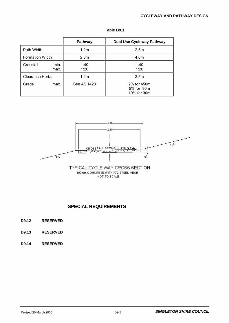
CYCLEWAY AND PATHWAY DESIGN
Revised 20 March 2000 D9-5 SINGLETON SHIRE COUNCIL
Table D9.1
Pathway Dual Use Cycleway Pathway
Path Width 1.2m 2.5m
Formation Width 2.0m 4.0m
Crossfall min.max.
1:401:20
1:401:20
Clearance Horiz. 1.2m 2.5m
Grade max. See AS 1428 2% for 450m5% for 90m10% for 30m
SPECIAL REQUIREMENTS
D9.12 RESERVED
D9.13 RESERVED
D9.14 RESERVED
DEVELOPMENT DESIGNSPECIFICATION
D10Modified 3
BUSHFIRE PROTECTION


BUSHFIRE PROTECTION
Revised 21 March 2000 D10-1 SINGLETON SHIRE COUNCIL
CONTENTS
CLAUSE PAGE
GENERAL.............................................................................................................................2
D10.01 SCOPE..................................................................................................................................2
D10.02 OBJECTIVES........................................................................................................................2
D10.03 REFERENCE AND SOURCE DOCUMENTS.........................................................................2
DESIGN CRITERIA ...............................................................................................................3
D10.04 GENERAL .............................................................................................................................3
D10.05 FIRE PROTECTION ZONES.................................................................................................3
D10.06 FUEL REDUCED ZONE........................................................................................................5
D10.07 FUEL FREE ZONE................................................................................................................5
D10.08 MODIFICATIONS TO FUEL REDUCED AND FUEL FREE ZONES ......................................6
D10.09 ACCESS TRACKS ................................................................................................................6
D10.10 STAGING WORKS................................................................................................................7
SPECIAL REQUIREMENTS .................................................................................................7
D10.11 RESERVED...........................................................................................................................7
D10.12 RESERVED...........................................................................................................................7
D10.13 RESERVED...........................................................................................................................7

BUSHFIRE PROTECTION
Revised 21 March 2000 D10-2 SINGLETON SHIRE COUNCIL
DEVELOPMENT DESIGN SPECIFICATION D10BUSHFIRE PROTECTION
GENERAL
D10.01 SCOPE
1. The work to be executed under this Specification consists of the design ofbushfire protection facilities to protect life and property and bring a fire to a halt.
2. The specification contains procedures for the design of fire protection facilities. Designs shall be carried out to satisfy requirements of the Council and the guidelinespublished by the Department of Bushfire Services, May 1991. Consultation withCouncil's Fire Control Officer may be required.
D10.02 OBJECTIVES
1. This specification aims to outline the requirements that will minimise bushfirehazard in developments. The requirements are particularly pertinent to ruraldevelopments but should be an integral part of urbanised development as well. Theconcepts proposed need to be incorporated at an early stage of development design.
RuralDevelopmentUrbanDevelopment
D10.03 REFERENCE AND SOURCE DOCUMENTS
(a) Council Specifications
C501 - Bushfire Protection (Perimeter Tracks)
(b) NSW Government Legislation
Environment Planning and Assessment Act 1979 - Section 94
(c) NSW Government Department Publications
Department of Bushfire Services (May 1991)- Planning for Bushfire Protection. A Guide for Land Use
Planners, Fire Authorities, Developer and Home Owner.
Department of Land and Water Conservation (formerly Land Management)- Soil Conservation Service 1983. Guidelines for Planning,
Construction and Maintenance of Tracks.
Ministry of Urban Affairs (formerly Environment) and Planning- "Planning Guidelines for Subdivisions in Bushfire Prone
Areas" 1985.
NSW Department of Urban Affairs (formerly Environment) and Planning- "Circular 74: Planning in Fire Prone Areas" 1984.
(d) Other
Board of Fire Commissioners- "Hazard Reduction for the Protection of Buildings in
Bushland areas" 1984.
Bush Fire Council of NSW

BUSHFIRE PROTECTION
Revised 21 March 2000 D10-3 SINGLETON SHIRE COUNCIL
- "Everyone's Guide to Bushfire Control" 1984.
- "Everyone's Guide to Bushfire Prevention in UrbanBushland Areas" 1986.
- "Everyone's Guide to Wild fire Prevention in Rural Areas"1986.
Californian Department of Forestry- "Fire Safety Guides for Residential Development in
California" 1980.
Insurance Council of Australia.- "Bushfire Safety in Urban Fringe Areas."
Luke, R.H. - "Before the Fires Start."
DESIGN CRITERIA
D10.04 GENERAL
1. Where a subdivision will abut unimproved timber in a bushfire prone area (asclassified by Council), perimeter tracks are to be located immediately between thecreated allotment and the bushland within a minimum cleared width of 6m, and have aminimum formed width of 4m. Such roads shall be adequately drained to provide allweather access for fire fighting vehicles.
PerimeterTracks
2. The perimeter track shall be contained within a 20m reservation whic h bordersthose allotments abutting the bushfire prone area. Such a reserve shall serve as a basisfor fire protection measures to be undertaken and will not be considered as part of anypublic reserve dedication applicable to the subdivision. There shall be no developmenton the forest side of the perimeter track.
20mReservation
3. Access is to be provided from the above described reservation from the localroad system at regular intervals in a system of ‘loops’.
Access
4. For those subdivisions receiving reticulated water, fire hydrants shall be situatedat appropriate intervals or near where potential fire hazard areas exist as determined byCouncil.
Fire Hydrants
5. Council’s Fire Control Officer shall be consulted for technical advice in relationto bushfire protection of subdivisions.
Consultation
6. Fire protection zones access tracks and perimeter tracks shall be clearlyindicated on the subdivision plan. Erosion control features and revegetationrequirements shall also be indicated in the subdivision plan.
7. Any clearing may require DLWC approval. Designer should consult with DLWCto determine whether approval is required under The Native Vegetation Act.
D10.05 FIRE PROTECTION ZONES
1. The provision of Fire Protection Zones ( FPZs) can only occur as part of thedevelopment of the subdivision pattern. Each individual allotment shall have adequatespace for the main building (usually a dwelling), an area of open space (front, back orside yard) and the FPZ (which may include part of the yard area and/or neighbouringproperties). Figure D10.1 illustrates a typical FPZ.
Part ofDevelopment

BUSHFIRE PROTECTION
D10-4 Revised 21 March 2000SINGLETON SHIRE COUNCIL
100m40m
Figure D10.1 Fire Protection Zone
2. FPZs shall be required for any development fronting a bush fire hazard area,whether a single dwelling, a group of isolated dwellings or an urban subdivision. Theyact as a buffer zone between the development and the fuel.
Buffer Zone
3. The primary purpose of FPZs is to ensure that a progressive reduction of fueloccurs between the bush fire hazard and any combustible structures within thedevelopment.
Reduction ofFuel
4. Apart from its primary purpose the FPZ serves a number of other importantpurposes, dependent upon local fire fighting policy. The FPZ shall be designed to:
OtherPurposes
(a) maximise the separation distance between high intensity fire and anystructure, thereby reducing the radiation and direct flame contact;
(b) provide an area where embers can fall with minimal opportunity tocreate further fire outbreaks;
(c) provide a safe access to a structure for fire fighters by reducing the heatlevel from the main fire;
(d) provide a safe retreat for fire fighters; and
(e) provide a clear control line from which to begin back burning or hazardreduction operations.
Safety requirements sometimes dictate that fires are fought from the propertyitself rather than along the perimeter track.
5. The FPZ incorporates up to three separate components:
(a) Fuel Reduced Zone (FRZ); and
(b) Fuel Free Zone (FFZ) incorporating:
(i) a perimeter road or reserve (which incorporates an accesstrack); and
SeparateComponents

BUSHFIRE PROTECTION
Revised 21 March 2000 D10-5 SINGLETON SHIRE COUNCIL
(ii) a set-back (currently defined by minimum lot depths), which isusually part of the allotment.
D10.06 FUEL REDUCED ZONE
1. The FRZ is located adjacent to the hazard:
Originally it would have been part of the bush fire hazard but has become an area wherethe fuel loadings are reduced through thinning of vegetation, mechanical clearing,hazard reduction burning or location of suitable developments such as playing fields orcar parks (provided it is wide enough).
Location
Reduced FuelLoadings
2. Fuel loadings within the FRZ shall be kept to a level where the fire intensityexpected will not impact on adjacent developments. In the absence of any policy to thecontrary, 8 tonnes per hectare is to be adopted.
Minimum FuelLoadings
3. The FRZ is to be included within the property being subdivided. Part of theDevelopment
4. For slopes greater than 18 degrees, the environmental consequences of groundclearing (erosion) may not be acceptable. Any clearing requires DLWC approval.
Clearing SteepSlopes
D10.07 FUEL FREE ZONE
1. The fuel free zone is located adjacent to, or is part of, the development andcomprises a perimeter road and a set-back.
(a) Perimeter Road
(i) The perimeter road or access trail lies between the FRZ and theboundary of the allotments.
Location
(ii) The concept of a perimeter road requires that one side of theroad has no fuel. Perimeter roads are not fire breaks in thesame sense as used in fire fighting operations. Their mainpurpose relates to reduction of radiation and provision of access. Without a fuel source on the other side, perimeter roads canhowever prove very effective fire breaks.
Concept
(iii) The reserve shall be a minimum of 40m wide, with a 6m accesstrack and passing bays every 200m. Passing bays are to be10m wide and 15m long.
Form
(iv) In designing for a perimeter road or track, the distance requiredmay not seem very great. Given that the probability of firejumping a fire break increases as the width decreases, thenareas where the highest intensity fires are likely should have firebreaks of greatest width.
Design
(v) Tracks shall be constructed to Soil Conservation Service (1983)guidelines.

BUSHFIRE PROTECTION
D10-6 Revised 21 March 2000SINGLETON SHIRE COUNCIL
Figure D10.2Perimeter Road Track
D10.08 MODIFICATIONS TO FUEL REDUCED AND FUEL FREE ZONES
1. Fire authorities would generally be reluctant to agree to modifications in thewidth of either the FRZ or the FFZ. If modifications were to be agreed, it would be afteran examination of the particular cases rather than according to any formula.
Reluctance ofFireAuthorities
2. Modifications would need to take account of adjacent or proposed development. Some difficulties arise where new development abuts existing development that is a firehazard because of the nature of its usage (eg forests, parks etc). The general principleis that fire protection should be shared by both users which may require a certain level ofnegotiation outside the planning system.
AdjacentDevelopment
3. Even without an extensive area of fuel outside the FRZ, intense fires candevelop if the FRZ has not been hazard-reduced and if the fire begins as a line ignitionfrom spotting embers.
4. Under adverse conditions fires moving up a slope may not be slowed by thepresence of rocky outcrops and ledges, even though the continuity of the fuel bed maybe broken.
D10.09 ACCESS TRACKS
1. The provision of adequate access tracks is also controlled by subdivision design.
Access tracks shall incorporate the following features.
Incorporatedin SubdivisionDesign

BUSHFIRE PROTECTION
Revised 21 March 2000 D10-7 SINGLETON SHIRE COUNCIL
(a) width, vertical clearances and any dips and crests which allow the twoway movement of firefighting appliances;
b) construction stan dards of roads and any bridges which allow for thecarrying of fully loaded fire appliances (28 tonnes or 8 tones per axle);
(c) curves which have a minimum inner radius of 12m and are minimal innumber;
(d) maximum grades which do not exceed 15% (1:7) and preferably notmore than 10% (1:10);
(e) clearly signposted roads;
(f) dead end roads which do not exceed 200 metres in length;
(g) dead ends which incorporate a minimum turning circle of 12.5m; and
(h) a subdivision road network which connects re gularly to any accesstracks.
D10.10 STAGING WORKS
1. When considering the rate of development, planners shall provide for initialdevelopment to occur on the hazard perimeter of the development. A line of dwellingswill tend to minimise the threat to the entire subdivision by limiting the hazard interface.
InitialDevelopmenton HazardPerimeter
2. Scattered developments on the other hand, will allow a continuous network offuel to threaten individual buildings until development is substantially underway.
ScatteredDevelopments
3. For similar reasons, new developments should be 'tacked' onto olddevelopments to minimise the hazard perimeter.
MinimiseHazardPerimeter
4. It is important that much of the bush fire protection is incorporated into thedesign of the development, rather than into individual allotments.
Incorporatedin SubdivisionDesign
SPECIAL REQUIREMENTS
D10.11 RESERVED
D10.12 RESERVED
D10.13 RESERVED