Embed Size (px)
Citation preview

PARTS AND OPERATION MANUALOPERATION AND PARTS MANUAL
PARTS LIST NO. M3870400004
Revision #2 (01/27/11)
®
MODEL DCA125USJ60 Hz GENERATOR
(JOHN DEERE 6068TF 275 DIESEL ENGINE)
To find the latest revision of thispublication, visit our website at:
www.multiquip.com
THIS MANUAL MUST ACCOMPANY THE EQUIPMENT AT ALL TIMES.

PAGE 2 — DCA-125USJ — OPERATION AND PARTS MANUAL — REV. #2 (01/27/11)
DCA-125USJ — OPERATION AND PARTS MANUAL — REV. #2 (01/27/11) — PAGE 3
1
NOTE PAGE
PAGE 4 — DCA-125USJ — OPERATION AND PARTS MANUAL — REV. #2 (01/27/11)
TABLE OF CONTENTS
COMPONENT DRACOMPONENT DRACOMPONENT DRACOMPONENT DRACOMPONENT DRAWINGSWINGSWINGSWINGSWINGSGenerator Assembly .................................................. 54-55Control Box Assembly ............................................... 56-59Engine & Radiator Assembly ..................................... 60-63Output Terminal Assembly ......................................... 64-65Battery Assembly ...................................................... 66-67Muffler Assembly ...................................................... 68-69Fuel Tank Assembly .................................................. 70-71Enclosure #1 Assembly ............................................ 72-75Enclosure #2 Assembly ............................................ 76-77Rubber Seals Assembly ............................................ 78-79Nameplate and Decals .............................................. 80-81
Terms and Condition of Sale — Parts ............................ 82
Specification and partnumber are subject tochange without notice.
NOTE
MQ POWER DCA12USJMQ POWER DCA12USJMQ POWER DCA12USJMQ POWER DCA12USJMQ POWER DCA12USJAC GENERAAC GENERAAC GENERAAC GENERAAC GENERATORTORTORTORTORCalifornia Proposition 65 Warning ..................................... 2Here's How To Get Help .................................................... 3Table Of Contents ............................................................. 4Parts Ordering Procedures ............................................... 5Specifications ................................................................... 6Dimensions (Top, Side, Front) .......................................... 7Safety Information ....................................................... 8-13Generator Decals ....................................................... 14-15Installation ................................................................. 16-17General Information ........................................................ 18Major Components ......................................................... 19Generator Control Panel ................................................. 21Engine Operating Panel ............................................. 22-23Output Terminal Panel Familiarization ........................ 24-26Load Application ............................................................. 27Generator Outputs .......................................................... 28Gauge Reading ............................................................... 29Output Terminal Panel Connections ........................... 30-31Pre Setup .................................................................. 32-35Generator Start-up Procedure (Manual) ..................... 36-37Generator Start-up Procedure (Auto Mode) .................... 38Generator Shut-Down Procedure .................................... 39Maintenance .............................................................. 40-42Trailer Brakes Maintenance ............................................ 43Trailer Maintenance .................................................... 44-45Trailer Wiring Diagram ..................................................... 46Generator Wiring Diagram ............................................... 47Engine Wiring Diagram ................................................... 48Generator Troubleshooting .............................................. 49Engine Controller Troubleshooting ................................... 50Explanation of Code in Remarks Column ....................... 52Suggested Spare Parts .................................................. 53

DCA-125USJ — OPERATION AND PARTS MANUAL — REV. #2 (01/27/11) — PAGE 5
1
PARTS ORDERING PROCEDURES
ww
w.m
ultiq
uip
.com
Ordering parts has never been easier! Choose from three easy options:
WE ACCEPT ALL MAJOR CREDIT CARDS!
When ordering parts, please supply:❒ Dealer Account Number❒ Dealer Name and Address❒ Shipping Address (if different than billing address)❒ Return Fax Number❒ Applicable Model Number❒ Quantity, Part Number and Description of Each Part
❒ Specify Preferred Method of Shipment: ✓ UPS/Fed Ex ✓ DHL ■ Priority One ✓ Truck ■ Ground ■ Next Day ■ Second/Third Day
If you have an MQ Account, to obtain a Username and Password, E-mail us at: [email protected].
To obtain an MQ Account, contact your District Sales Manager for more information.
Order via Internet (Dealers Only):Order parts on-line using Multiquip’s SmartEquip website! ■ View Parts Diagrams ■ Order Parts ■ Print Specification Information
Note: Discounts Are Subject To Change
Goto www.multiquip.com and click on Order Parts to log in and save!
Use the internet and qualify for a 5% Discount on Standard orders for all orders which include complete part numbers.*
Order via Fax (Dealers Only):All customers are welcome to order parts via Fax.Domestic (US) Customers dial: 1-800-6-PARTS-7 (800-672-7877)
Fax your order in and qualify for a 2% Discount on Standard orders for all orders which include complete part numbers.*
Order via Phone: Domestic (US) Dealers Call: 1-800-427-1244
Best Deal!
International Customers should contact their local Multiquip Representatives for Parts Ordering information.
Non-Dealer Customers: Contact your local Multiquip Dealer for parts or call 800-427-1244 for help in locating a dealer near you.
Note: Discounts Are Subject To Change
Effective: January 1st, 2006
NOTICE
All orders are treated as Standard Orders and will ship the same day if received prior to 3PM PST.

PAGE 6 — DCA-125USJ — OPERATION AND PARTS MANUAL — REV. #2 (01/27/11)
DCA-125USJ — SPECIFICATIONS
snoitacificepSrotareneG.1elbaT
ledoM JSU521ACD
epyT suonorhcnysepytdetcetorpnepo,detalitnevfles,dleifgnivloveRrotareneg
noitcennoCerutamrA lartueNhtiwratS gaZgiZ
esahP 3 elgniS
tuptuOybdnatS )WK011(AVK731 WK97
tuptuOemirP )WK001(AVK521 WK27
egatloV V084roV042 V021/042
ycneuqerF zH06
deepS mpr0081
rotcaFrewoP 8.0 1
rewoPCA.xuA zH06,esahPelgniS
egatloV V021
tuptuO )2xWK4.2(WK8.4
snoitacificepSenignE.2elbaT
ledoM 572FT8606EREEDNHOJ
epyT degrahc-obrut,noitcejnitcerid,delooc-retaw,elcyc4
srednilyCfo.oN srednilyc6
ekortSxeroB )mm721xmm601(.ni5x.ni91.4
tuptuOdetaR mpr0081/PH051
tnemecalpsiD )cc008,6(.ni.uc514
gnitratS CDV21cirtcelE
yticapaCtnalooC )sretil8.61(.lag4.4
yticapaCliOebuL )sretil9.81(.lag3.5
epyTleuF leuFleseiD2#
yticapaCknaTleuF )sretil046(.lag961
noitpmusnoCleuFtarh/)L0.92(.lag7.7 daollluf tarh/)L9.12(.lag8.5 daol4/3
tarh/)L5.41(.lag8.3 daol2/1 tarh/)L3.9(.lag5.2 daol4/1
yrettaB 64puorGICBV21

DCA-125USJ — OPERATION AND PARTS MANUAL — REV. #2 (01/27/11) — PAGE 7
1
DCA-125USJ — DIMENSIONS (TOP, SIDE AND FRONT)
Figure 1. Dimensions
PAGE 8 — DCA-125USJ — OPERATION AND PARTS MANUAL — REV. #2 (01/27/11)
DCA-125USJ — SAFETY INFORMATIONDo not operate or service the equipment before reading the entire manual. Safety precautions should be followed at all times when operating this equipment. Failure to read and understand the safety messages and operating instructions could result in injury to yourself and others.
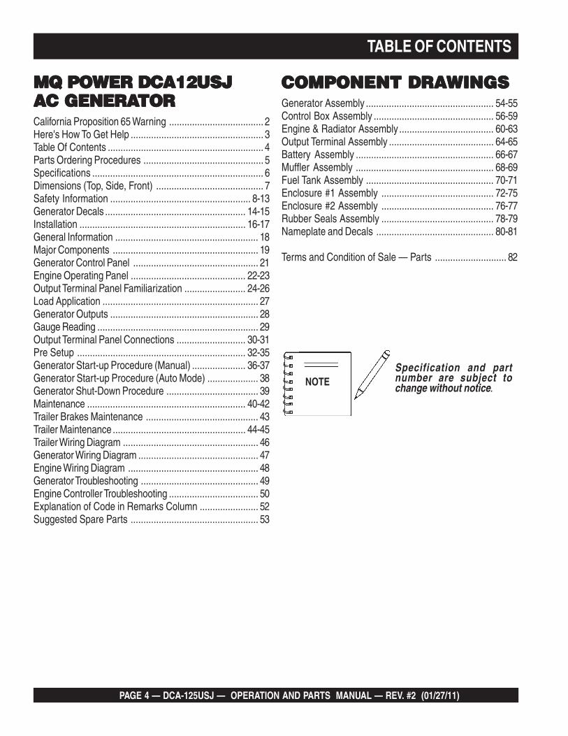
SAFETY MESSAGES
The four safety messages shown below will inform you about potential hazards that could injure you or others. The safety messages specifically address the level of exposure to the operator and are preceded by one of four words: DANGER, WARNING, CAUTION or NOTICE.
SAFETY SYMBOLS
DANGER
Indicates a hazardous situation which, if not avoided, WILL result in DEATH or SERIOUS INJURY.
WARNING
Indicates a hazardous situation which, if not avoided, COULD result in DEATH or SERIOUS INJURY.
CAUTION
Indicates a hazardous situation which, if not avoided, COULD result in MINOR or MODERATE INJURY.
NOTICE
Addresses practices not related to personal injury.
Potential hazards associated with the operation of thisequipment will be referenced with hazard symbols which may appear throughout this manual in conjunction with safety messages.

DCA-125USJ — OPERATION AND PARTS MANUAL — REV. #2 (01/27/11) — PAGE 9
1
DCA-125USJ — SAFETY INFORMATIONGENERAL SAFETY
CAUTION
NEVER operate this equipment without proper protective clothing, shatterproof glasses, respiratory protection, hearing protection, steel-toed boots and other protective devices required by the job or city and state regulations.
NEVER operate this equipment when not feeling well due to fatigue, illness or when under medication.
NEVER operate this equipment under the influence of drugs or alcohol.
ALWAYS check the equipment for loosened threads or bolts before starting.
DO NOT use the equipment for any purpose other than its intended purposes or applications.
NOTICE
This equipment should only be operated by trained and qualified personnel 18 years of age and older.
Whenever necessary, replace nameplate, operation and safety decals when they become difficult read.
Manufacturer does not assume responsibility for any accident due to equipment modifications. Unauthorized equipment modification will void all warranties.
NEVER use accessories or attachments that are not recommended by Multiquip for this equipment. Damage to the equipment and/or injury to user may result.
ALWAYS know the location of the nearest fire extinguisher.
ALWAYS know the location of the nearest first aid kit.
ALWAYS know the location of the nearest phone or keep a phone on the job site. Also, know the phone numbers of the nearest ambulance, doctor and fire department. This information will be invaluable in the case of an emergency.
GENERATOR SAFETY
DANGER
NEVER operate the equipment in an explosive atmosphere or near combustible materials. An explosion or fire could result causing severe bodily harm or even death.
WARNING
NEVER disconnect any emergency or safety devices.These devices are intended for operator safety.Disconnection of these devices can cause severe injury,bodily harm or even death. Disconnection of any of thesedevices will void all warranties.
CAUTION
NEVER lubricate components or attempt service on a running machine.
NOTICE
ALWAYS ensure generator is on level ground before use.
ALWAYS keep the machine in proper running condition.
Fix damage to machine and replace any broken parts immediately.
ALWAYS store equipment properly when it is not beingused. Equipment should be stored in a clean, dry location out of the reach of children and unauthorized personnel

PAGE 10 — DCA-125USJ — OPERATION AND PARTS MANUAL — REV. #2 (01/27/11)
DCA-125USJ — SAFETY INFORMATION
ENGINE SAFETY
DANGER
The engine fuel exhaust gases contain poisonous carbon monoxide. This gas is colorless and odorless, and can cause death if inhaled.
The engine of this equipment requires an adequate free flow of cooling air. NEVER operate this equipment in any enclosed or narrow area where free flow of the air is restricted. If the air flow is restricted it will cause injury to people and property and serious damage to the equipment or engine.
WARNING
DO NOT place hands or fingers inside engine compartment when engine is running.
NEVER operate the engine with heat shields or guards removed.
Keep fingers, hands hair and clothing away from all moving parts to prevent injury.
DO NOT remove the radiator cap while the engine is hot. High pressure boiling water will gush out of the radiator and severely scald any persons in the general area of the generator.
DO NOT remove the coolant drain plug while the engine is hot. Hot coolant will gush out of the coolant tank and severely scald any persons in the general area of the generator.
DO NOT remove the engine oil drain plug while the engine is hot. Hot oil will gush out of the oil tank and severely scald any persons in the general area of the generator.
CAUTION
NEVER touch the hot exhaust manifold, muffler or cylinder. Allow these parts to cool before servicing equipment.
NOTICE
NEVER run engine without an air filter or with a dirty air filter. Severe engine damage may occur. Service air filterfrequently to prevent engine malfunction.
NEVER tamper with the factory settings of the engine or engine governor. Damage to the engine or equipment can result if operating in speed ranges above the maximum allowable.
Wet stacking is a common problem with diesel engines which are operated for extended periods with light or no load applied. When a diesel engine operates without sufficient load (less than 40% of the rated output), it will not operate at its optimum temperature. This will allowunburned fuel to accumulate in the exhaust system, which can foul the fuel injectors, engine valves and exhaust system, including turbochargers, and reducethe operating performance.
In order for a diesel engine to operate at peak efficiency, it must be able to provide fuel and air in the proper ratio and at a high enough engine temperature for the engine to completely burn all of the fuel.
Wet stacking does not usually cause any permanentdamage and can be alleviated if additional load is applied to relieve the condition. It can reduce the system performance and increase maintenance. Applying an increasing load over a period of time until the excess fuel is burned off and the system capacity is reached usually can repair the condition. This can take several hours to burn off the accumulated unburned fuel.
State Health Safety Codes and Public Resources Codes specify that in certain locations, spark arresters must be used on internal combustion engines that use hydrocarbon fuels. A spark arrester is a device designed to prevent accidental discharge of sparks or flamesfrom the engine exhaust. Spark arresters are qualified and rated by the United States Forest Service for this purpose. In order to comply with local laws regarding spark arresters, consult the engine distributor or the local Health and Safety Administrator.

DCA-125USJ — OPERATION AND PARTS MANUAL — REV. #2 (01/27/11) — PAGE 11
1
DCA-125USJ — SAFETY INFORMATION
FUEL SAFETY
DANGER
DO NOT start the engine near spilled fuel or combustible fluids. Diesel fuel is extremely flammable and its vapors can cause an explosion if ignited.
ALWAYS refuel in a well-ventilated area, away from sparks and open flames.
ALWAYS use extreme caution when working with flammable liquids.
DO NOT fill the fuel tank while the engine is running or hot.
DO NOT overfill tank, since spilled fuel could ignite if it comes into contact with hot engine parts or sparks from the ignition system.
Store fuel in appropriate containers, in well-ventilated areas and away from sparks and flames.
NEVER use fuel as a cleaning agent.
DO NOT smoke around or near the equipment. Fire or explosion could result from fuel vapors or if fuel is spilled on a hot engine.
TOWING SAFETY
CAUTION
Check with your local county or state safety towing regulations, in addition to meeting Department of Transportation (DOT) Safety Towing Regulations, before towing your generator.
Refer to MQ Power trailer manual for additional safety information.
In order to reduce the possibility of an accident while transporting the generator on public roads, ALWAYS make sure the trailer that supports the generator and the towing vehicle are mechanically sound and in good operating condition.
ALWAYS shutdown engine before transporting
Make sure the hitch and coupling of the towing vehicle are rated equal to, or greater than the trailer “grossvehicle weight rating.”
ALWAYS inspect the hitch and coupling for wear. NEVER tow a trailer with defective hitches, couplings, chains, etc.
Check the tire air pressure on both towing vehicle and trailer. Trailer tires should be inflated to 50 psi cold. Also check the tire tread wear on both vehicles.
ALWAYS make sure the trailer is equipped with a safetychain.
ALWAYS properly attach trailer’s safety chains to towingvehicle.
ALWAYS make sure the vehicle and trailer directional, backup, brake and trailer lights are connected and working properly.
DOT Requirements include the following:
wraps.
The maximum speed for highway towing is 55 MPH unless posted otherwise. Recommended off-road towing is not to exceed 15 MPH or less depending on type of terrain.
Avoid sudden stops and starts. This can cause skidding, or jack-knifing. Smooth, gradual starts and stops willimprove towing.
Avoid sharp turns to prevent rolling.
Trailer should be adjusted to a level position at all times when towing.
Raise and lock trailer wheel stand in up position when towing.
Place chock blocks underneath wheel to prevent rolling while parked.
Place support blocks underneath the trailer’s bumper to prevent tipping while parked.
Use the trailer’s swivel jack to adjust the trailer height to a level position while parked.

PAGE 12 — DCA-125USJ — OPERATION AND PARTS MANUAL — REV. #2 (01/27/11)
DCA-125USJ — SAFETY INFORMATION
ELECTRICAL SAFETY
DANGER
DO NOT touch output terminals during operation. Contact with output terminals during operation can cause electrocution, electrical shock or burn.
The electrical voltage required to operate the generator can cause severe injury or even death through physical contact with live circuits. Turn generator and all circuit breakers OFF before performing maintenance on the generator or making contact with output terminals.
NEVER insert any objects into the output receptacles during operation. This is extremely dangerous. The possibility exists of electrical shock, electrocution or death.
Backfeed to a utility system can cause electrocution and/or property damage. NEVER connect the generator to a building’s electrical system without a transfer switch or other approved device. All installations should be performed by a licensed electrician in accordance with all applicable laws and electrical codes. Failure to do so could result in electrical shock or burn, causing serious injury or even death.
Power Cord/Cable Safety
DANGER
NEVER let power cords or cables lay in water.
NEVER stand in water while AC power from the generator is being transferred to a load.
NEVER use damaged or worn cables or cords when connecting equipment to generator. Inspect for cuts in the insulation.
NEVER grab or touch a live power cord or cable with wet hands. The possibility exists of electrical shock, electrocution or death.
Make sure power cables are securely connected to the generator’s output receptacles. Incorrect connectionsmay cause electrical shock and damage to the generator.
NOTICE
ALWAYS make certain that proper power or extension cord has been selected for the job. See Cable Selection Chart in this manual.
Grounding Safety
DANGER
ALWAYS make sure that electrical circuits are properlygrounded to a suitable earth ground (ground rod) per the National Electrical Code (NEC) and local codesbefore operating generator. Severe injury or death by electrocution can result from operating an ungroundedgenerator.
NEVER use gas piping as an electrical ground.
DCA-125USJ — OPERATION AND PARTS MANUAL — REV. #2 (01/27/11) — PAGE 13
1
DCA-125USJ — SAFETY INFORMATION
BATTERY SAFETY
DANGER
DO NOT drop the battery. There is a possibility that the battery will explode.
DO NOT expose the battery to open flames, sparks, cigarettes, etc. The battery contains combustible gases and liquids. If these gases and liquids come into contact with a flame or spark, an explosion could occur.
WARNING
ALWAYS wear safety glasses when handling the battery to avoid eye irritation. The battery contains acids that can cause injury to the eyes and skin.
Use well-insulated gloves when picking up the battery.
ALWAYS keep the battery charged. If the battery is not charged, combustible gas will build up.
ALWAYS recharge the battery in a well-ventilated environment to avoid the risk of a dangerous concentration of combustible gasses.
If the battery liquid (dilute sulfuric acid) comes into contact with clothing or skin, rinse skin or clothing immediately with plenty of water.
If the battery liquid (dilute sulfuric acid) comes into contact with eyes, rinse eyes immediately with plenty of water and contact the nearest doctor or hospital to seek medical attention.
CAUTION
ALWAYS disconnect the NEGATIVE battery terminal before performing service on the generator.
ALWAYS keep battery cables in good working condition. Repair or replace all worn cables.
ENVIRONMENTAL SAFETY
NOTICE
Dispose of hazardous waste properly. Examples of potentially hazardous waste are used motor oil, fuel and fuel filters.
DO NOT use food or plastic containers to dispose of hazardous waste.
DO NOT pour waste, oil or fuel directly onto the ground, down a drain or into any water source.

PAGE 14 — DCA-125USJ — OPERATION AND PARTS MANUAL — REV. #2 (01/27/11)
The DCA-125USJ generator is equipped with a number of safety decals (Figures 2 and 3). These decals are provided foroperator safety and maintenance information. The illustration below and on the preceding page show the decals as theyappear on the machine. Should any of these decals become unreadable, replacements can be obtained from your dealer.
Figure 2. Generator Decals
DCA-125USJ — GENERATOR DECALS

DCA-125USJ — OPERATION AND PARTS MANUAL — REV. #2 (01/27/11) — PAGE 15
1 Figure 3. Generator Decals (Cont.)
DCA-125USJ — GENERATOR DECALS

PAGE 16 — DCA-125USJ — OPERATION AND PARTS MANUAL — REV. #2 (01/27/11)
Figure 4. Typical Generator Grounding Application
DCA-125USJ — INSTALLATION

DCA-125USJ — OPERATION AND PARTS MANUAL — REV. #2 (01/27/11) — PAGE 17
1
Generator Grounding
To guard against electrical shock and possible damage tothe equipment, it is important to provide a good EARTHground.
Article 250 (Grounding) of the National Electrical Code (NEC)provides guide lines for proper grounding and specifies thatthe cable ground shall be connected to the grounding systemof the building as close to the point of cable entry aspractical.
NEC articles 250-64(b) and 250-66 set the followinggrounding requirements:
1. Use one of the following wire types to connect thegenerator to earth ground.
a. Copper - 10 AWG (5.3 mm2) or larger.
b. Aluminum - 8 AWG (8.4 mm2) or larger.
2. When grounding the generator (Figure 2) connect theground cable between the lock washer and the nut onthe generator and tighten the nut fully. Connect the otherend of the ground cable to earth ground.
3. NEC article 250-52(c) specifies that the earth groundrod should be buried aminimum of 8 ft. into the ground.
When connecting the generator toany buildings electrical systemALWAYS consult with a licensedelectrician.
DCA-125USJ — INSTALLATION
NOTE
Outdoor Installation
Install the generator in a area that is free of debris,bystanders, and overhead obstructions. Make sure thegenerator is on secure level ground so that it cannot slide orshift around. Also install the generator in a manner so thatthe exhaust will not be discharged in the direction of nearbyhomes.
The installation site must be relatively free from moistureand dust. All electrical equipment should be protected fromexcessive moisture. Failure to do will result in deteriorationof the insulation and will result in short circuits and grounding.
Foreign materials such as dust, sand, lint and abrasivematerials have a tendency to cause excessive wear toengine and alternator parts.
Indoor Installation
Exhaust gases from diesel engines are extremely poisonous.Whenever an engine is installed indoors the exhaust fumesmust be vented to the outside. The engine should be installedat least two feet from any outside wall. Using an exhaustpipe which is too long or too small can cause excessiveback pressure which will cause the engine to heat excessivelyand possibly burn the valves.
Mounting
The generator must be mounted on a solid foundation (suchas concrete) and set firmly on the foundation to isolatevibration of the generator when it is running. The generatormust set at least 6 inches above the floor or grade level (inaccordance to NFPA 110, Chapter 5-4.1). DO NOT removethe metal skids on the bottom of the generator. They are toresist damage to the bottom of the generator and to maintainalignment.
Pay close attention to ventilation when operating thegenerator inside tunnels and caves. The engine exhaustcontains noxious elements. Engine exhaust must be routedto a ventilated area.
CAUTION - EXHAUST HAZARD
PAGE 18 — DCA-125USJ — OPERATION AND PARTS MANUAL — REV. #2 (01/27/11)
DCA-125USJ — GENERAL INFORMATION
DCA-125USJ Series FamiliarizationGeneratorThe MQ Power Model DCA-125USJ is a 100 kW generator(Figure 5) that is designed as a high quality portable (requiresa trailer for transport) power source for telecom sites, lightingfacilities, power tools, submersible pumps and otherindustrial and construction machinery.Engine Operating PanelThe “Engine Operating Panel” is provided with the following: Tachometer Water Temperature Gauge Oil Pressure Gauge Charging Ammeter Gauge Fuel Level Gauge Pre-heat Lamp Panel Light/Panel Light Switch Auto ON/OFF Engine Controller (MPEC) Fuel Leak Detected Alarm LampGenerator Control PanelThe “Generator Control Panel” is provided with the following: Frequency Meter (Hz) AC Ammeter (Amps) AC Voltmeter (Volts) Ammeter Change-Over Switch Voltmeter Change-Over Switch Voltage Regulator 3-Pole, 300 amp Main Circuit BreakerControl BoxThe “Control Box”, located behind the Generator ControlPanel, is provided with the following: Automatic Voltage Regulator Current Transformer Over-Current Relay Voltage Rectifer Starter Relay Engine Controller (Computer Controlled) Voltage Selector SwitchOutput Terminal PanelThe “Output Terminal Panel” is provided with the following:
Three 120/240V output receptacles (CS-6369), 50A Three auxilliary circuit breakers, 50A Two 120V output receptacles (GFCI), 20A Two GFCI circuit breakers, 20A Five output terminal lugs (3Ø power) Battery Charger (Optional) Water Heater (Optional)
Open Delta Excitation SystemThe DCA-125USJ generator is equipped with the state ofthe art "Open-Delta" excitation system. The open deltasystem consist of an electrically independent winding woundamong stationary windings of the AC output section.There are four connections of the open delta A, B, C and D.During steady state loads, the power from the voltage regulatoris supplied from the parallel connections of A to B, A to D,and C to D. These three phases of the voltage input to thevoltage regulator are then rectified and are the excitationcurrent for the exciter section.When a heavy load, such as a motor starting or a shortcircuit occurs, the automatic voltage regulator (AVR)switches the configuration of the open delta to the seriesconnection of B to C. This has the effect of adding the voltagesof each phase to provide higher excitation to the excitersection and thus better voltage response during theapplication of heavy loads.The connections of the AVR to the AC output windings arefor sensing only. No power is required from these windings.The open-delta design provides virtually unlimited excitationcurrent, offering maximum motor starting capabilities. Theexcitation does not have a "fixed ceiling" and respondsaccording the demands of the required load.EngineThe DCA-125USJ is powered by a 4 cycle, water cooled,direct injection, turbocharged JOHN DEERE Model6068TF275 Diesel Engine. This engine is designed to meetevery performance requirement for the generator. ReferenceTable 1 for engine specifications.In keeping with MQ Power's policy of constantly improvingits products, the specifications quoted herein are subject tochange without prior notice.Electric Governor SystemThe electric governor system controls the RPMs of theengine. When the engine demand increases or decreases,the governor system regulates the frequency variation to±.25%.Extension CablesWhen electric power is to be provided to various tools orloads at some distance from the generator, extension cordsare normally used. Cables should be sized to allow fordistance in length and amperage so that the voltage dropbetween the generator and point of use (load) is held to aminimum. Use the cable selection chart (Table 5) as a guidefor selecting proper extension cable size.

DCA-125USJ — OPERATION AND PARTS MANUAL — REV. #2 (01/27/11) — PAGE 19
1
DCA-125USJ — MAJOR COMPONENTS
Figure 5. Major Components
3elbaT . stnenopmoCrojaMrotareneG
.ONMETI NOITPIRCSED
1 ylbmessArelffuM
2 ylbmessAenignE
3 ylbmessAerusolcnE
4 ylbmessArotareneG
5 ylbmessAlanimreTtuptuO
6 ylbmessAknaTleuF
7 ylbmessAyrettaB
8 ylbmessAlenaPlortnoCrotareneG
9 ylbmessAlenaPgnitarepOenignE
PAGE 20 — DCA-125USJ — OPERATION AND PARTS MANUAL — REV. #2 (01/27/11)
NOTE PAGE

DCA-125USJ — OPERATION AND PARTS MANUAL — REV. #2 (01/27/11) — PAGE 21
1
DCA-125USJ — GENERATOR CONTROL PANEL
The definitions below describe the controls and functions ofthe DCA-125USJ Generator Control Panel (Figure 6).
1. Main Circuit Breaker – This three-pole, 300A mainbreaker is provided to protect the the U,V, and W OutputTerminal Lugs from overload.
2. Frequency Meter – Indicates the output frequency inhertz (Hz). Normally 60 Hz.
3. AC Ammeter – Indicates the amount of current the loadis drawing from the generator per leg selected by theammeter phase-selector switch.
4. Ammeter Change-Over Switch – This switch allowsthe AC ammeter to indicate the current flowing to theload connected to any phase of the output terminals, orto be switched off. This switch does not effect thegenerator output in any fashion, it is for current readingonly.
5. AC Voltmeter – Indicates the output voltage present atthe U,V, and W Output Terminal Lugs.
6. Voltmeter Change-Over Switch – This switch allowsthe AC voltmeter to indicate phase to phase voltagebetween any two phases of the output terminals or tobe switched off.
7. Voltage Regulator Control – Allows ±15% manualadjustment of the generator’s output voltage.
Located behind the generator control panel is the GeneratorControl Box. This box contains some of the necessaryelectronic components required to make the generatorfunction.
The Control Box is equipped with the following majorcomponents: Over-Current Relay Voltage Rectifer (AVR) Starter Relay Current Transformer Voltage Selector Switch
Figure 6. Generator Control Panel
Remember the overcurrentrelay monitors the currentflowing from the U,V, and WOutput Terminal Lugs to theload.
In the event of a short circuit or over current condition, it willautomatically trip the 60 amp main breaker.
To restore power to the Output Terminal Panel, press thereset button on the overcurrent relay and place the maincircuit breaker in the closed position (ON).
NOTE

PAGE 22 — DCA-125USJ — OPERATION AND PARTS MANUAL — REV. #2 (01/27/11)
Figure 7. Engine Operating Panel
DCA-125USJ — ENGINE OPERATING PANEL
DCA-125USJ — OPERATION AND PARTS MANUAL — REV. #2 (01/27/11) — PAGE 23
1
DCA-125USJ — ENGINE OPERATING PANEL
The definitions below describe the controls and functions ofthe DCA-125USJ Engine Operating Panel (Figure 7).
1. Panel Light – Normally used in dark areas or at nighttime. When activated, panel lights will illuminate. Whenthe generator is not in use be sure to turn the panellight switch to the OFF position.
2. Panel Light Switch – When activated will turn on controlpanel light.
3. Oil Pressure Gauge – During normal operation thisgauge be should read between 35 to 65 psi. Whenstarting the generator the oil pressure may read a littlehigher, but after the engine warms up the oil pressureshould return to the correct pressure range.
4. Water Temperature Gauge – During normal operationthis gauge be should read between 180° and 221°F.
5. Charging Ammeter Gauge – Indicates the currentbeing supplied by the engine’s alternator which providescurrent for generator’s control circuits and batterycharging system.
6. Fuel Gauge - Indicates amount of diesel fuel available.
7. Tachometer – Indicates engine speed in RPM’s for 60Hz operation. This meter should indicate 1800 RPM’swhen the rated load is applied. In addition a built in hourmeter will record the number of operational hours thatthe generator has been in use.
8. Pre-Heat Lamp – As the engine cranks, this lamp willilluminate to indicate automatic preheating of the engine.When the lamp turns off, the engine has been preheatedand will start automatically.
9. Fuel Leak Detected Alarm Lamp – This lamp willilluminate when a leak in the fuel tank containmentenclosure is detected.
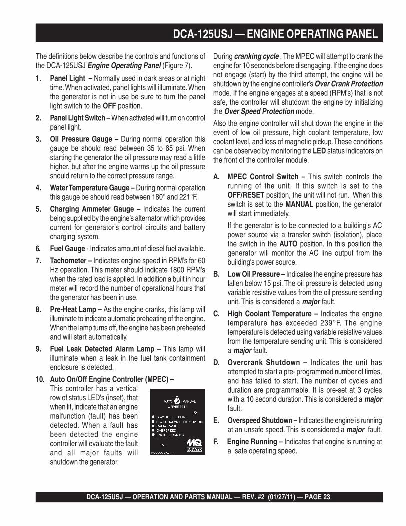
10. Auto On/Off Engine Controller (MPEC) –This controller has a verticalrow of status LED's (inset), thatwhen lit, indicate that an enginemalfunction (fault) has beendetected. When a fault hasbeen detected the enginecontroller will evaluate the faultand all major faults willshutdown the generator.
A. MPEC Control Switch – This switch controls therunning of the unit. If this switch is set to theOFF/RESET position, the unit will not run. When thisswitch is set to the MANUAL position, the generatorwill start immediately.
If the generator is to be connected to a building's ACpower source via a transfer switch (isolation), placethe switch in the AUTO position. In this position thegenerator will monitor the AC line output from thebuilding's power source.
B. Low Oil Pressure – Indicates the engine pressure hasfallen below 15 psi. The oil pressure is detected usingvariable resistive values from the oil pressure sendingunit. This is considered a major fault.
C. High Coolant Temperature – Indicates the enginetemperature has exceeded 239F. The enginetemperature is detected using variable resistive valuesfrom the temperature sending unit. This is considereda major fault.
D. Overcrank Shutdown – Indicates the unit hasattempted to start a pre- programmed number of times,and has failed to start. The number of cycles andduration are programmable. It is pre-set at 3 cycleswith a 10 second duration. This is considered a majorfault.
E. Overspeed Shutdown – Indicates the engine is runningat an unsafe speed. This is considered a major fault.
F. Engine Running – Indicates that engine is running ata safe operating speed.
During cranking cycle , The MPEC will attempt to crank theengine for 10 seconds before disengaging. If the engine doesnot engage (start) by the third attempt, the engine will beshutdown by the engine controller’s Over Crank Protectionmode. If the engine engages at a speed (RPM's) that is notsafe, the controller will shutdown the engine by initializingthe Over Speed Protection mode.
Also the engine controller will shut down the engine in theevent of low oil pressure, high coolant temperature, lowcoolant level, and loss of magnetic pickup. These conditionscan be observed by monitoring the LED status indicators onthe front of the controller module.
PAGE 24 — DCA-125USJ — OPERATION AND PARTS MANUAL — REV. #2 (01/27/11)
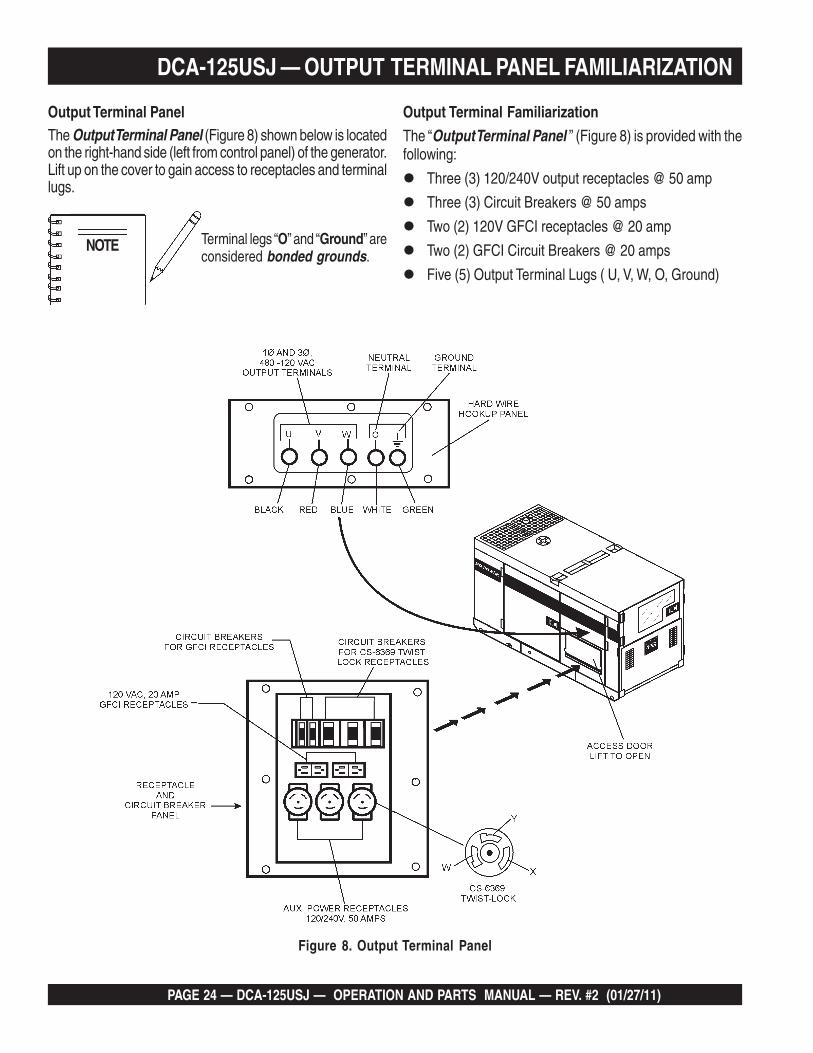
Output Terminal Familiarization
The “Output Terminal Panel ” (Figure 8) is provided with thefollowing:
Three (3) 120/240V output receptacles @ 50 amp
Three (3) Circuit Breakers @ 50 amps
Two (2) 120V GFCI receptacles @ 20 amp
Two (2) GFCI Circuit Breakers @ 20 amps
Five (5) Output Terminal Lugs ( U, V, W, O, Ground)
Output Terminal PanelThe Output Terminal Panel (Figure 8) shown below is locatedon the right-hand side (left from control panel) of the generator.Lift up on the cover to gain access to receptacles and terminallugs.
NOTE Terminal legs “O” and “Ground” areconsidered bonded grounds.
Figure 8. Output Terminal Panel
DCA-125USJ — OUTPUT TERMINAL PANEL FAMILIARIZATION

DCA-125USJ — OPERATION AND PARTS MANUAL — REV. #2 (01/27/11) — PAGE 25
1
120 VAC GFCI ReceptaclesThere are two 120 VAC, 20 amp GFCI (Duplex Nema 5-20R)recepacles provided on the output terminal panel. Thesereceptacles can be accessed in any voltage selector switchposition. Each receptacle is protected by a 20 amp circuitbreaker. These breakers are located directly above the GFCIreceptacles. Remember the load output (current) of bothGFCI receptacles is dependent on the load requirements ofthe UVWO terminals.
Pressing the reset button resets the GFCI receptacle afterbeing tripped. Pressing the "Test Button" (See Figure 9) inthe center of the receptacle will check the GFCI function.Both receptacles should be tested at least once a month.
Figure 9. G.F.C.I. Receptacle
Each auxilliary receptacle is protected by a 50 amp circuitbreaker. These breakers are located directly above the GFCIreceptacles. Remember the load output (current) on all threereceptacles is dependent on the load requirements of theOutput Terminal Lugs.
Turn the voltage regulator control knob (Figure 11) on thecontrol panel to obtain the desired voltage. Turning the knobclockwise will increase the voltage, turning the knob counter-clockwise will decrease the voltage.
Figure 10. 120/240V Twist-LockAuxiliary Receptacles
DCA-125USJ — OUTPUT TERMINAL PANEL FAMILIARIZATION
Twist Lock Dual Voltage 120/240 VAC ReceptaclesThere are three 120/240V, 50 amp auxilliary twist-lock(CS-6369) recepacles (Figure 10) provided on the outputterminal panel.These receptacles can only be accessedwhen the voltage selector switch is placed in the single-phase 240/120 position.
Figure 11. Voltage Regulator Control Knob
Figure 12. Plastic Face Plate (Output Terminal Lugs)
Removing the Plastic Face Plate (Hard Wire Hookup Panel)The Output Terminal Lugs are protected by a plastic faceplate cover (Figure 12). Un-screw the securing bolts and liftthe plastic terminal cover to gain access to the terminalenclosure.After the load wires have been securely attached to theterminal lugs, reinstall the plastic face plate.

PAGE 26 — DCA-125USJ — OPERATION AND PARTS MANUAL — REV. #2 (01/27/11)
Figure 13. Connecting Loads
Connecting LoadsLoads can be connected to the generator by the Ouput TerminalLugs or the convienience receptacles. (See Figure 13). Makesure to read the operation manual before attempting to connecta load to the generator.
To protect the output terminals from overload, a3-pole, 300A main circuit breaker is provided. Make sure toswitch ALL circuit breakers to the OFF position prior tostarting the engine.
DCA-125USJ — OUTPUT TERMINAL PANEL FAMILIARIZATION
Over Current RelayAn over current relay (Figure 14) is connected to the maincircuit breaker. In the event of an overload, both the circuitbreaker and the over current relay may trip. If the circuitbreaker can not be reset, the reset button on the over cur-rent relay must be pressed. The over current relay is lo-cated in the control box.
Figure 14. Over Current Relay
Blower Fan
This unit has an intake fan located at the rear of the machineto draw outside air into the cabinet to cool the engine. Thefan has a 10 amp AC fuse located beneath the VoltageSelector Switch (Figure 15).
Figure 15. Blower Fan Fuse
The blower fan fuse has current runningthrough it any time the engine isoperating. This fuse IS NOT connectedto the main circuit breaker of thegenerator. Attempting to replace the fusewith the engine and/or generatoroperating could result in electrocution and severe bodilyharm. ALWAYS turn the unit completely off beforeattempting to replace or handle the fuse.
CAUTION - ELECTRICAL SHOCK HAZARD
DCA-125USJ — OPERATION AND PARTS MANUAL — REV. #2 (01/27/11) — PAGE 27
1
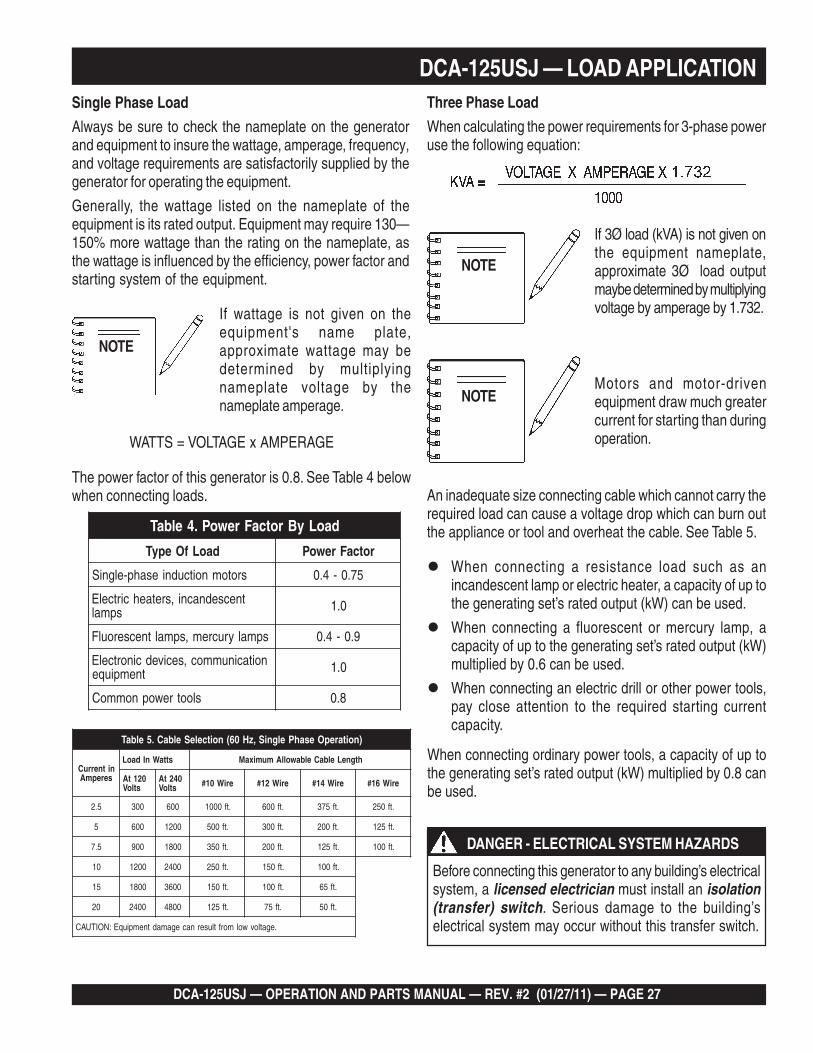
DCA-125USJ — LOAD APPLICATIONSingle Phase Load
Always be sure to check the nameplate on the generatorand equipment to insure the wattage, amperage, frequency,and voltage requirements are satisfactorily supplied by thegenerator for operating the equipment.
Generally, the wattage listed on the nameplate of theequipment is its rated output. Equipment may require 130—150% more wattage than the rating on the nameplate, asthe wattage is influenced by the efficiency, power factor andstarting system of the equipment.
Motors and motor-drivenequipment draw much greatercurrent for starting than duringoperation.
When connecting ordinary power tools, a capacity of up tothe generating set’s rated output (kW) multiplied by 0.8 canbe used.
If wattage is not given on theequipment's name plate,approximate wattage may bedetermined by multiplyingnameplate voltage by thenameplate amperage.
The power factor of this generator is 0.8. See Table 4 belowwhen connecting loads.
If 3Ø load (kVA) is not given onthe equipment nameplate,approximate 3Ø load outputmaybe determined by multiplyingvoltage by amperage by 1.732.
When connecting a resistance load such as anincandescent lamp or electric heater, a capacity of up tothe generating set’s rated output (kW) can be used.
When connecting a fluorescent or mercury lamp, acapacity of up to the generating set’s rated output (kW)multiplied by 0.6 can be used.
When connecting an electric drill or other power tools,pay close attention to the required starting currentcapacity.
NOTE
WATTS = VOLTAGE x AMPERAGE
Three Phase Load
When calculating the power requirements for 3-phase poweruse the following equation:
NOTE
An inadequate size connecting cable which cannot carry therequired load can cause a voltage drop which can burn outthe appliance or tool and overheat the cable. See Table 5.
NOTE
daoLyBrotcaFrewoP.4elbaT
daoLfOepyT rotcaFrewoP
srotomnoitcudniesahp-elgniS 57.0-4.0
tnecsednacni,sretaehcirtcelEspmal 0.1
spmalyrucrem,spmaltnecseroulF 9.0-4.0
noitacinummoc,secivedcinortcelEtnempiuqe 0.1
slootrewopnommoC 8.0
)noitarepOesahPelgniS,zH06(noitceleSelbaC.5elbaT
nitnerruCserepmA
sttaWnIdaoL htgneLelbaCelbawollAmumixaM
021tAstloV
042tAstloV eriW01# eriW21# eriW41# eriW61#
5.2 003 006 .tf0001 .tf006 .tf573 .tf052
5 006 0021 .tf005 .tf003 .tf002 .tf521
5.7 009 0081 .tf053 .tf002 .tf521 .tf001
01 0021 0042 .tf052 .tf051 .tf001
51 0081 0063 .tf051 .tf001 .tf56
02 0042 0084 .tf521 .tf57 .tf05
.egatlovwolmorftlusernacegamadtnempiuqE:NOITUAC
Before connecting this generator to any building’s electricalsystem, a licensed electrician must install an isolation(transfer) switch. Serious damage to the building’selectrical system may occur without this transfer switch.
DANGER - ELECTRICAL SYSTEM HAZARDS

PAGE 28 — DCA-125USJ — OPERATION AND PARTS MANUAL — REV. #2 (01/27/11)
GFCI Receptacle Load Capability
The load capability of the GFCI receptacles is directly re-lated to the voltage being supplied at either the output termi-nals or the 3 twist lock auxilliary receptacles.
Tables 8 and 9 show what amount of current is available atthe GFCI receptacles when the output terminals and twistlock receptacles are in use. Be careful that your load doesnot to exceed the available current capability at the recep-tacles.
1.8elbaT Ø ytilibapaCdaoLelcatpeceRICFGesUniWK
)9636SC(kcoL-tsiwTdaoLelbaliavA)spmA(tnerruC
V021/042Ø1 AMENxelpuDICFGV021R02-5
27 08.07 elcatpecerrepspma56.96 elcatpecerrepspma014.86 elcatpecerrepspma512.76 elcatpecerrepspma02
3.9elbaT Ø ytilibapaCdaoLelcatpeceRICFGesUniAVK
)slanimreTOWVU(daoLelbaliavA)spmA(tnerruC
V084/042Ø3 AMENxelpuDICFGV021R02-5
521 0121 elcatpecerrepspma5711 elcatpecerrepspma01311 elcatpecerrepspma51801 elcatpecerrepspma02
Voltage Selector SwitchThe voltage selector switch (Figure 16) is located abovethe output terminal panel’s Hard Wire Hook-up Panel. Ithas been provided for ease of voltage selection.
Voltage Selector Switch Locking ButtonThe voltage selector switch has a locking button to protectthe generator and load from being switched while the engineis running. To lock the voltage selector switch, press andhold the red button located at the bottom of the switch.
Figure 16. Voltage Selector Switch
DCA-125USJ — GENERATOR OUTPUTSGenerator AmperageTable 7 describes the generator’s current output capabilityfor both 1Ø-phase and 3Ø phase applications.
elbaliavAsegatloV.6elbaT
esahPeerhT)elbahctiwS(
V802 V022 V042 V614 V044 V084
esahPelgniS)elbahctiwS(
V021 V721 V931 V042 V452 V772
sgnitaRerepmArotareneG.7elbaTJSU521-ACD Wk AVk V021 V802 V042 V084
esahPelgniS 27 A/N 2xA103 A/N A103 A/N
*esahPeerhT 001 521 A/N A743 A103 A051
8.0=rotcaFrewoP*
Generator Output VoltagesA wide range of voltages are available to supply voltage formany different applications. Voltages are selected by usingthe voltage selector switch (Figure 15). To obtain some ofthe voltages as listed in Table 6 (see below) will require afine adjustment using the voltage regulator (VR) controlknob located on the control panel.
CAUTION - VOLTAGE SELECTOR SWITCH
NEVER change the position of the voltage selectorswitch while the engine is runnng. ALWAYS place circuitbreaker in the open position before selecting voltage.
DCA-125USJ — OPERATION AND PARTS MANUAL — REV. #2 (01/27/11) — PAGE 29
1
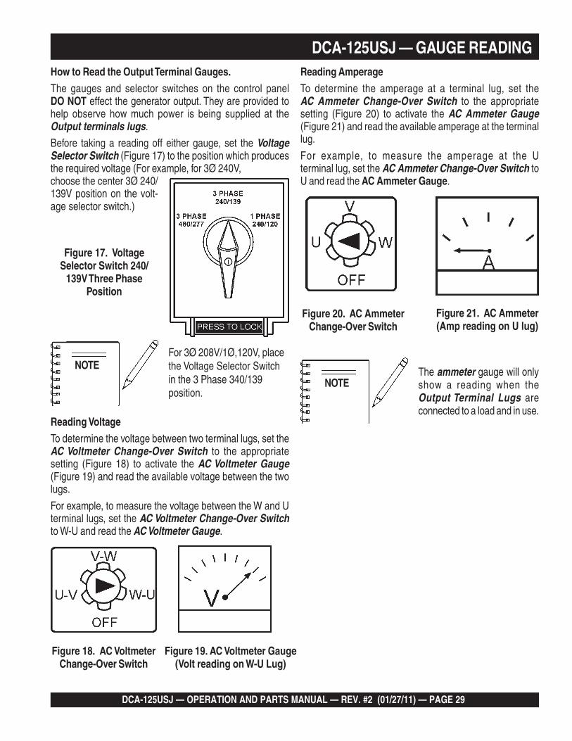
DCA-125USJ — GAUGE READINGHow to Read the Output Terminal Gauges.The gauges and selector switches on the control panelDO NOT effect the generator output. They are provided tohelp observe how much power is being supplied at theOutput terminals lugs.
Before taking a reading off either gauge, set the VoltageSelector Switch (Figure 17) to the position which producesthe required voltage (For example, for 3Ø 240V,choose the center 3Ø 240/139V position on the volt-age selector switch.)
Figure 17. VoltageSelector Switch 240/
139V Three PhasePosition
Figure 18. AC VoltmeterChange-Over Switch
Figure 19. AC Voltmeter Gauge(Volt reading on W-U Lug)
For 3Ø 208V/1Ø,120V, placethe Voltage Selector Switchin the 3 Phase 340/139position.
Figure 21. AC Ammeter(Amp reading on U lug)
Figure 20. AC AmmeterChange-Over Switch
The ammeter gauge will onlyshow a reading when theOutput Terminal Lugs areconnected to a load and in use.
NOTE
Reading VoltageTo determine the voltage between two terminal lugs, set theAC Voltmeter Change-Over Switch to the appropriatesetting (Figure 18) to activate the AC Voltmeter Gauge(Figure 19) and read the available voltage between the twolugs.
For example, to measure the voltage between the W and Uterminal lugs, set the AC Voltmeter Change-Over Switchto W-U and read the AC Voltmeter Gauge.
NOTE
Reading AmperageTo determine the amperage at a terminal lug, set theAC Ammeter Change-Over Switch to the appropriatesetting (Figure 20) to activate the AC Ammeter Gauge(Figure 21) and read the available amperage at the terminallug.
For example, to measure the amperage at the Uterminal lug, set the AC Ammeter Change-Over Switch toU and read the AC Ammeter Gauge.

PAGE 30 — DCA-125USJ — OPERATION AND PARTS MANUAL — REV. #2 (01/27/11)
Figure 22. Voltage Selector Switch 240/139VThree-Phase Position
DCA-125USJ — OUTPUT TERMINAL PANEL CONNECTIONS
UVWO Terminal Output VoltagesVarious output voltages can be obtained using the OutputTerminal Lugs.. The voltages at the terminals are depen-dent on the position of the Voltage Selector Switch and theadjustment of the Voltage Regulator Control Knob.
Remember the voltage selector switch determines the rangeof the output voltage. The voltage regulator (VR) allows theuser to increase or decrease the selected voltage.
3Ø 240/139 Output Terminal Lug Voltages
1. Place the voltage selector switch in the 3Ø 240/139position as shown in Figure 22.
Figure 23. Output Terminal Lugs240/139V Three Phase Connections
2. Connect the load wires to the Output Terminal Lugs asshown in Figure 23.
3. Turn the voltage regulator knob (Figure 24) clockwise toincrease voltage output, turn counterclockwise todecrease voltage output.
3Ø 208V/1Ø120V Output Terminal Lug Voltages
1. Place the voltage selector switch in the 3Ø 240/139position as shown in Figure 25.
Figure 24. Voltage Regulator Knob (139V/240V)
Use this position for3Ø-208 or 1Ø120V.
2. Connect the load wires to the Output Terminal Lugs asshown in Figure 26.
3. Turn the voltage regulator knob (Figure 24) clockwise toincrease voltage output, turn counterclockwise todecrease voltage output.
NOTE
To achieve a 3Ø 208V outputthe voltage selector switchmust be in the 3Ø-240/139position and the voltageregulator must be adjusted to208V.
Figure 26. Output Terminal Lugs3Ø-208V/120V Connections
Figure 25. Voltage SelectorSwitch 3Ø-208V/1Ø-120VThree-Phase Position
DCA-125USJ — OPERATION AND PARTS MANUAL — REV. #2 (01/27/11) — PAGE 31
1
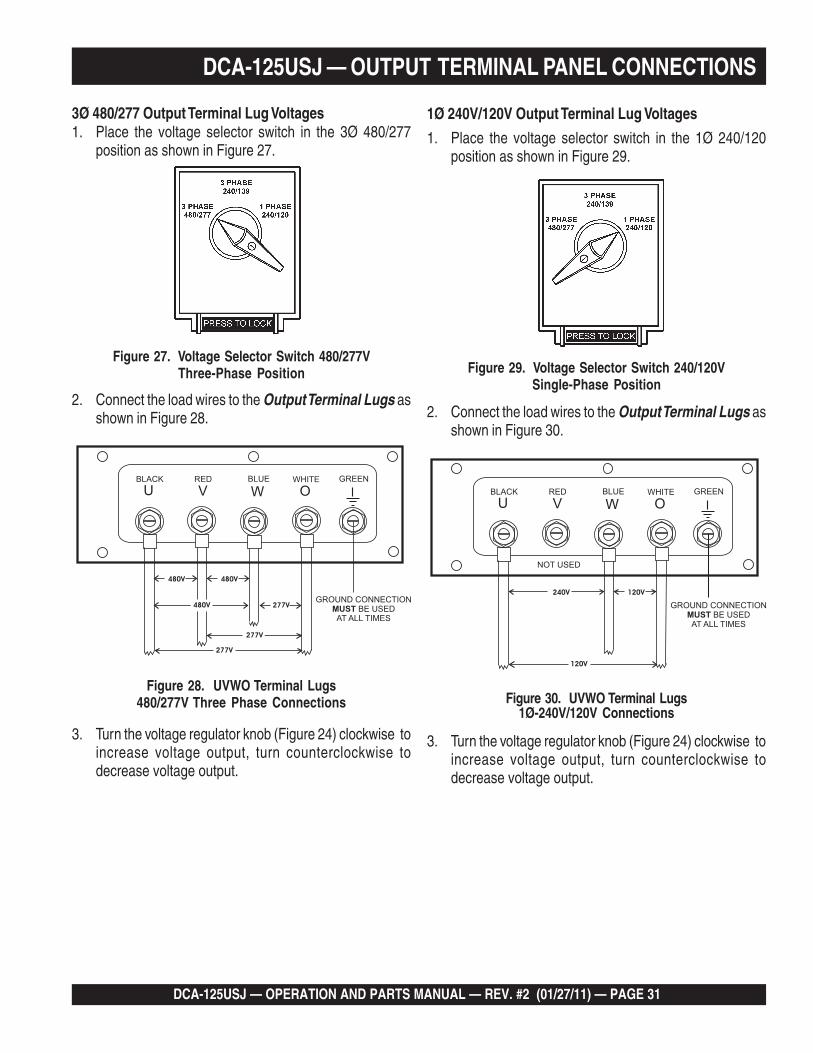
Figure 27. Voltage Selector Switch 480/277VThree-Phase Position
3Ø 480/277 Output Terminal Lug Voltages1. Place the voltage selector switch in the 3Ø 480/277
position as shown in Figure 27.
Figure 28. UVWO Terminal Lugs480/277V Three Phase Connections
2. Connect the load wires to the Output Terminal Lugs asshown in Figure 28.
3. Turn the voltage regulator knob (Figure 24) clockwise toincrease voltage output, turn counterclockwise todecrease voltage output.
1Ø 240V/120V Output Terminal Lug Voltages
1. Place the voltage selector switch in the 1Ø 240/120position as shown in Figure 29.
2. Connect the load wires to the Output Terminal Lugs asshown in Figure 30.
3. Turn the voltage regulator knob (Figure 24) clockwise toincrease voltage output, turn counterclockwise todecrease voltage output.
Figure 30. UVWO Terminal Lugs1Ø-240V/120V Connections
DCA-125USJ — OUTPUT TERMINAL PANEL CONNECTIONS
Figure 29. Voltage Selector Switch 240/120VSingle-Phase Position

PAGE 32 — DCA-125USJ — OPERATION AND PARTS MANUAL — REV. #2 (01/27/11)
DCA-125USJ — PRE-SETUP
Figure 31. Engine Oil Dipstick
When checking the engine oil, be sure to check if the oil isclean. If the oil is not clean, drain the oil by removing the oildrain plug, and refill with the specified amount of oil as outlinedin the John Deere Engine Owner's Manual. Oil should bewarm before draining.
Other types of motor oils may be substituted if they meetthe following requirements:
API Service Classification CC/SC API Service Classification CC/SD API Service Classification CC/SE API Service Classification CC/SF
Circuit Breakers
To protect the generator from an overload, a 3-pole, 110 amp,main circuit breaker is provided to protect the U,V, and WOutput Terminals from overload. In addition two single-pole,20 amp GFCI circuit breakers are provided to protect theGFCI receptacles from overload. Three 50 amp load circuitbreakers have also been provided to protect the auxiliaryreceptacles from overload. Make sure to switch ALL circuitbreakers to the OFF position prior to starting the engine.
Lubrication Oil
Fill the engine crankcase with lubricating oil through the fillerhole, but DO NOT overfill. Make sure the generator is level.and verify that the oil level is maintained between the twonotches (Figure 31) on the dipstick. See Table 10 for properselection of engine oil.
Figure 32. Internal Fuel Tank System
The generator unit has an internal fuel tank located at thebottom of the cabinet (Figure 32). ALWAYS fill the fuel tankwith clean and fresh #2 diesel fuel. DO NOT fill the fueltanks beyond their capacities.
Pay attention to the fuel tank capacity when replenishingfuel.The fuel tank cap must be closed tightly after filling.Handle fuel in a safety container. If the container does nothave a spout, use a funnel. Wipe up any spilled fuelimmediately.
-40
-30
-10
-20
-22
-40
-4
-14
032
50
68
86
104
122
10
20
30
40
50
F C
10W
40
30
AR
CT
ICO
IL
5W
30
10W
/40
15W
30
10W
30
10W 20W
40
OIL: SAE
Table 10. Recommended Motor Oil
Refilling the Fuel System
Fuel Check
ONLY properly trained personel who have read andunderstand this section should refill the fuel tank system.
CAUTION - REFUELING THE GENERATOR
Fuel spillage on a hot engine can cause a fire or explosion.If fuel spillage occurs, wipe up the spilled fuel completelyto prevent fire hazards. NEVER smoke around or near thegenerator.
DANGER - EXPLOSION/FIRE HAZARDS

DCA-125USJ — OPERATION AND PARTS MANUAL — REV. #2 (01/27/11) — PAGE 33
1
DCA-125USJ — PRE-SETUP
Figure 33. Only Fill on Level Ground
ONLY! use #2 diesel fuel whenrefueling.
NOTE
3. NEVER overfill fuel tank – It is important to read thefuel gauge when filling trailer fuel tank. DO NOT wait forfuel to rise in filler neck (Figure 35).
Figure 35. Full Fuel Tank
Figure 36. Fuel Expansion
2. Open cabinet doors on the “right side” of the generator(from generator control panel position). Remove fuel capand fill tank (Figure 34).
Figure 34. Fueling the Generator
Refueling Procedure:
1. Level Tanks – Make sure fuel cells are level with theground. Failure to do so will cause fuel to spill from thetank before reaching full capacity (Figure 32).
ALWAYS place trailer on firm level ground before refuelingto prevent spilling and maximize the amount of fuel thatcan be pumped into the tank.
CAUTION - REFUELING THE GENERATOR
Diesel fuel and its vapors are dangerousto your health and the surroundingenvironment. Avoid skin contact and/orinhaling fumes.
WARNING - RESPIRATORY HAZARDS
DO NOT OVER-FILL fuel system. Leave room for fuelexpansion. Fuel expands when heated (Figure 36).
CAUTION - REFUELING THE GENERATOR

PAGE 34 — DCA-125USJ — OPERATION AND PARTS MANUAL — REV. #2 (01/27/11)
Coolant (John Deere Antifreeze/Summer Coolant/Water)John Deere recommends John Deere Antifreeze/SummerCoolant for use in thier engines, which can be purchased inconcentrate (and mixed with 50% demineralized water) orpre-diluted. See the John Deere Engine Owner's Manualfor further details.
If adding coolant/antifreeze mix to the radiator, DO NOT removethe radiator cap until the unit has completely cooled. Thepossibility of hot! coolant exists which can cause severeburns.
Day-to-day addition of coolant is done from the recoverytank. When adding coolant to the radiator, DO NOT removethe radiator cap until the unit has completely cooled. SeeTable 11 for engine, radiator, and recovery tank coolantcapacities. Make sure the coolant level in the recovery tankis always between the "H" and the "L" markings.
Operation Freezing Weather
When operating in freezing weather, be certain the properamount of antifreeze (Table 12) has been added.
Cleaning the Radiator
The engine may overheat if the radiator fins becomeoverloaded with dust or debris. Periodically clean the radiatorfins with compressed air. Cleaning inside the machine isdangerous, so clean only with the engine turned off and thenegative battery terminal disconnected.
Air Cleaner
Periodic cleaning/replacement is necessary. Inspect it inaccordance with the John Deere Engine Owner's Manual.
Fan Belt Tension
A slack fan belt may contribute to overheating, or toinsufficient charging of the battery. Inspect the fan belt fordamage and wear and adjust it in accordance with the JohnDeere Engine Owner's Manual.
The fan belt tension is proper if the fan belt bends 10 to 15mm (Figure 37) when depressed with the thumb as shownbelow.
Figure 37. Fan Belt Tension
DCA-125USJ — PRE-SETUP
When the antifreeze is mixed withwater, the antifreeze mixing ratiomust be less than 50%.
NOTE
ezeerF-itnA.21elbaTserutarepmeTgnitarepO
%loVezeerF-itnA
tnioPgnizeerF
C° F°
05 73- 43-
yticapaCtnalooC.11elbaT
rotaidaRdnaenignE )sretil8.61(.laG4.4
knaTevreseR )sretil9.1(strauQ2
NEVER place hands nearthe belts or fan while thegenerator set is running.
CAUTION - ROTATING PARTS
If adding coolant/antifreeze mix to theradiator, DO NOT remove the radiator capuntil the unit has completely cooled. Thepossibility of hot! coolant exists whichcan cause severe burns.
WARNING - BURN HAZARDS

DCA-125USJ — OPERATION AND PARTS MANUAL — REV. #2 (01/27/11) — PAGE 35
1
DCA-125USJ — PRE-SETUP
When connecting battery do the following:
1. NEVER connect the battery cables to the batteryterminals when the MPEC Control Switch is in eitherthe MANUAL position. ALWAYS make sure that theMPEC Control Switch is in the OFF/RESET positionwhen connecting the battery.
2. Place a small amount of battery terminal treatmentcompound around both battery terminals. This will ensurea good connection and will help prevent corrosion aroundthe battery terminals.
Figure 38. Battery Connections
Alternator
The polarity of the alternator is negative grounding type. Whenan inverted circuit connection takes place, the circuit will bein short circuit instantaneously resulting the alternator failure.
DO NOT put water directly on the alternator. Entry of waterinto the alternator can cause corrision and damage thealternator.
Wiring
Inspect the entire generator for bad or worn electrical wiringor connections. If any wiring or connections are exposed(insulation missing) replace wiring immediately.
Piping and Hose Connection
Inspect all piping, oil hose, and fuel hose connections forwear and tightness. Tighten all hose clamps and check hosesfor leaks.
If any hose (fuel or oil) lines are defective replace themimmediately.
If the battery cable is connectedincorrectly, electrical damage tothe generator will occur. Pay closeattention to the polarity of thebattery when connecting thebattery.
NOTE
Battery
This unit is of negative ground DO NOT connect in reverse.Always maintain battery fluid level between the specifiedmarks. Battery life will be shortened, if the fluid level are notproperly maintained. Add only distilled water whenreplenishment is necessary.
DO NOT over fill. Check to see whether the battery cablesare loose. Poor contact may result in poor starting ormalfunctions. Always keep the terminals firmly tightened.Coating the terminals with an approved battery terminaltreatment compound. Replace battery with onlyrecommended type battery. The battery type used in thisgenerator is BCI Group 27.
The battery is sufficiently charged if the specific gravity ofthe battery fluid is 1.28 (at 68° F). If the specific gravityshould fall to 1.245 or lower, it indicates that the battery isdead and needs to be recharged or replaced.
Before charging the battery with an external electric source,be sure to disconnect the battery cables.
Battery Cable Installation
ALWAYS be sure the battery cables (Figure 38) are properlyconnected to the battery terminals as shown below. TheRED cable is connected to the positive terminal of the battery,and the BLACK cable is connected to the negative terminalof the battery.
ALWAYS disconnect the negative terminal FIRST andreconnect negative terminal LAST.
CAUTION - BATTERY SERVICING SAFETY
Inadequate battery connections may cause poor startingof the generator, and create other malfunctions.
CAUTION - BATTERY SERVICING SAFETY

PAGE 36 — DCA-125USJ — OPERATION AND PARTS MANUAL — REV. #2 (01/27/11)
8. Place the MPEC Control Switch in the MANUALposition to start the engine (Figure 42).
8. Verify that the Engine Runningstatus LED on the MPEC unit(Figure 44) is ON (lit) after theengine has been started.
Figure 44. Engine RunningLED (ON)
Starting (Manual)
Figure 42. MPEC Control Switch(Manual Position)
Figure 43. Pre-Heat Lamp
In cold weather conditions, placing the MPEC ControlSwitch in the MANUAL position will preheat and startthe engine AUTOMATICALLY. The Preheat Lamp(Figure 43) will turn off when the engine has started.
7. Once the engine starts, let the engine run for 1-2 minutes.Listen for any abnormal noises.
DCA-125USJ — GENERATOR START-UP PROCEDURE (MANUAL)
Figure 40. Engine Enclosure Doors
1. Place the main, G.F.C.I. and aux. circuit breakers (Figure 39)in the OFF position prior to starting the engine.
2. Connect the load to the receptacles or the OutputTerminal Lugs as shown in Figure 13. These loadconnection points can be found on the output terminalpanel and the output terminal panel’s hard wire hookuppanel.
3. The output terminal lugs are protected by a plastic cover.Remove this cover to gain access to the terminals.Tighten terminal nuts securely to prevent load wires fromslipping out.
4. Close all engine enclosure doors (Figure 40).
Figure 39. Main, Aux. and GFCICircuit Breakers (OFF)
5. Place the voltage selector switchin the desired voltage position(Figure 41).
Figure 41. Voltage SelectorSwitch
The engine's exhaust contains harmful emissions.ALWAYS have adequate ventilation when operating.Direct exhaust away from nearby personnel.
Before Starting
CAUTION - LETHAL EXHAUST HAZARD
NEVER! manually start the engine with the main, GFCIor auxiliary circuit breakers in the ON (closed) position.
WARNING - STARTING THE GENERATOR
DCA-125USJ — OPERATION AND PARTS MANUAL — REV. #2 (01/27/11) — PAGE 37
1
DCA-125USJ — GENERATOR START-UP PROCEDURE (MANUAL)
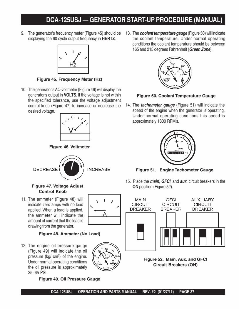
Figure 47. Voltage AdjustControl Knob
Figure 48. Ammeter (No Load)
11. The ammeter (Figure 48) willindicate zero amps with no loadapplied. When a load is applied,the ammeter will indicate theamount of current that the load isdrawing from the generator.
10. The generator's AC-voltmeter (Figure 46) will display thegenerator’s output in VOLTS. If the voltage is not withinthe specified tolerance, use the voltage adjustmentcontrol knob (Figure 47) to increase or decrease thedesired voltage.
Figure 46. Voltmeter
Figure 45. Frequency Meter (Hz)
9. The generator's frequency meter (Figure 45) should bedisplaying the 60 cycle output frequency in HERTZ.
Figure 51. Engine Tachometer Gauge
14. The tachometer gauge (Figure 51) will indicate thespeed of the engine when the generator is operating.Under normal operating conditions this speed isapproximately 1800 RPM’s.
13. The coolant temperature gauge (Figure 50) will indicatethe coolant temperature. Under normal operatingconditions the coolant temperature should be between165 and 215 degrees Fahrenheit (Green Zone).
Figure 50. Coolant Temperature Gauge
12. The engine oil pressure gauge(Figure 49) will indicate the oilpressure (kg/ cm2) of the engine.Under normal operating conditionsthe oil pressure is approximately35~65 PSI.
Figure 49. Oil Pressure Gauge
Figure 52. Main, Aux. and GFCICircuit Breakers (ON)
15. Place the main, GFCI, and aux. circuit breakers in theON position (Figure 52).

PAGE 38 — DCA-125USJ — OPERATION AND PARTS MANUAL — REV. #2 (01/27/11)
DCA-125USJ — GENERATOR START-UP PROCEDURE (AUTO MODE)
16. Observe the generator's ammeter (Figure 53) and verifyit reads the anticipated amount of current with respectto the load. The ammeter will only display a currentreading if a load is in use.
Figure 53. Ammeter (Load)
17. The generator will run until manually stopped or anabnormal condition occurs.
When the generator is set in theAUTO mode, the generator willautomically start in the event ofcomercial power falling below aprescribed level by means of acontact closure that is generatedautomatically by a transfer switch.
NOTE
Starting (Auto Mode)
Before connecting this generator to anybuilding’s electrical system, a licensedelectrician must install an isolation(transfer) switch. Serious damage to thebuilding’s electrical system may occurwithout this transfer switch.
DANGER - ELECTRICAL SYSTEM HAZARDS
When connecting the generator to a isolation (transfer)switch, ALWAYS have power applied to the generator'sinternal battery charger. This will ensure that the enginewill not fail due to a dead battery.
CAUTION - BACKUP GENERATOR USE
When running the generator in the AUTO mode, rememberthe generator can start up at any time without warning.NEVER attempt to perform any maintenance when thegenerator is in the auto mode.
WARNING - AUTO MODE MAINTENANCE
When the MPEC Control Switchis placed in the AUTO position,the engine glow plugs will bewarmed and the engine will startautomatically.
NOTE
CAUTION - ENGINE SPEED SWITCH
The Engine Speed Switch must be set to the “High”position when running in the Auto-Start mode. Failing toset the switch in the proper position can result in damageto your generator when it turns on.
1. Perform steps 1 through 5 in the Before Starting sectionas outlined in the Manual Starting Procedure.
2. Place the MPEC Control Switch (Figure 54) in the AUTOposition
3. Continue operating the generator as outlined in theManual Start-up procedure (start at step 9).
Figure 54. MPEC Control Switch (AUTO)
When starting generator in AUTO mode use the "ManualStart-up" procedure except where noted (see below).
DCA-125USJ — OPERATION AND PARTS MANUAL — REV. #2 (01/27/11) — PAGE 39
1
DCA-125USJ — GENERATOR SHUT-DOWN PROCEDURE
Normal Shutdown Procedure
To shutdown the generator use the following procedure:
1. Place both the MAIN, GFCI and LOAD circuit breakersas shown in Figure 38 to the OFF position.
3. Let the engine cool by running it at low speed for 3-5minutes with no load applied.
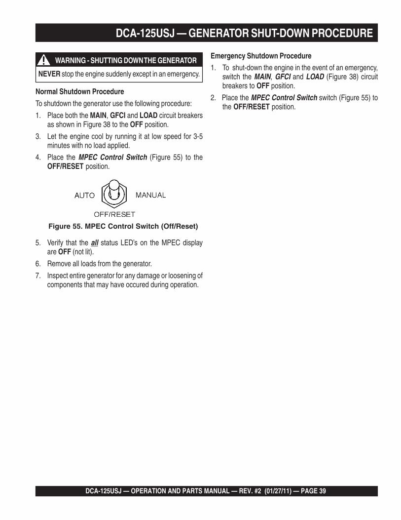
4. Place the MPEC Control Switch (Figure 55) to theOFF/RESET position.
Figure 55. MPEC Control Switch (Off/Reset)
5. Verify that the all status LED’s on the MPEC displayare OFF (not lit).
6. Remove all loads from the generator.
7. Inspect entire generator for any damage or loosening ofcomponents that may have occured during operation.
Emergency Shutdown Procedure
1. To shut-down the engine in the event of an emergency,switch the MAIN, GFCI and LOAD (Figure 38) circuitbreakers to OFF position.
2. Place the MPEC Control Switch switch (Figure 55) tothe OFF/RESET position.
NEVER stop the engine suddenly except in an emergency.
WARNING - SHUTTING DOWN THE GENERATOR

PAGE 40 — DCA-125USJ — OPERATION AND PARTS MANUAL — REV. #2 (01/27/11)
ECNANETNIAM/NOITCEPSNI.31ELBAT srH01YLIAD srH052 srH005 srH0001
ENIGNE
sleveLdiulFenignEkcehC X
renaelCriAkcehC X
leveLdicAyrettaBkcehC X
noitidnoCtleBnaFkcehC X
skaeLrofkcehC X
straPfogninesooLrofkcehC X
*retliFdnaliOenignEecalpeR 1 X
retliFriAnaelC X
lwoBrotarepeSretaW/retliFleuFkcehC X
edistuOdnaedisnI,tinUnaelC X
retliFleuFegnahC X
*leveLnoitcetorPtnalooCkcehCdnarotaidaRnaelC 2 X
*tnemelEretliFriAecalpeR 3 X
*spmalCdnasesoHllakcehC 4 X
knaTleuFfoedisnInaelC X
ROTARENEGsmhoM3revOecnatsiseRnoitalusnIerusaeM X
gniraeBtroppuSraeRrotoRkcehC X
.ylnoemittsrif,sruoh001taretliffnalioenigneecalpeR1*
.tnaloocenigneehtegrahcerot")S'ACS(sevitaddAtnalooClatnemelppuS"ddA2*
H.ni52(mm526fomuccavaswohsrotacidninoitcirtsernehwtnemeleretlifriayramirpecalpeR3* 2 .)0
htiw,toofrephcni2/1atsaeltasiesohybolbehtfoepolsehttahterusne,decalperebotsdeenesohybwolbfI4*.lioro/dnaerutsiomtcellocdluoctahtspidrosgason
DCA-125USJ — MAINTENANCE
Service DailyIf the engine is operating in very dusty or dry grass conditions, aclogged air cleaner will result. This can lead to a loss of power,excessive carbon buildup in the combustion chamber and highfuel consumption. Change air cleaner more frequently if theseconditions exists.
Fuel AdditionAdd diesel fuel (the grade may vary according to season andlocations).
Removing Water from the Fuel TankAfter prolonged use, water and other impurities accumulate inthe bottom of the tank. Occasionally inspect the fuel tank forwater contamination and drain the contents if required.
During cold weather, the more empty volume inside the tank,the easier it is for water to condense. This can be reduced bykeeping the tank full with diesel fuel.
General InspectionPrior to each use, the generator should be cleaned and inspectedfor deficiencies. Check for loose, missing or damaged nuts, boltsor other fasteners. Also check for fuel, oil, and coolant leaks.
Engine Side (Refer to the Engine Instruction Manual)
Air Cleaner
Every 250 hours: Remove air cleaner element and clean theheavy duty paper element with light spray of compressedair. Replace the air cleaner as needed.
Air Cleaner with Dust IndicatorThis indicator is attached to the air cleaner. When the air cleanerelement is clogged, air intake restriction becomes greater andthe dust indicator signal shows RED meaning the element needschanging or service. After changing the air element, press thedust indicator button to reset the indicator.

DCA-125USJ — OPERATION AND PARTS MANUAL — REV. #2 (01/27/11) — PAGE 41
1
DCA-125USJ — MAINTENANCE
Generator Storage
For longe term storage of the generator the following isrecommended:
Fill the fuel tank completely. Treat with a fuel stabilizerif necessary.
Completely drain the oil from the crankcase and refill ifnecessary with fresh oil.
Clean the entire generator, internal and external.
Cover the generating set and store in a clean, dry place.
Disconnect the battery.
Make sure engine coolant is at proper level.
If generator is mounted on a trailer, jack trailer up andplace on blocks so tires do not touch the ground or blockand completely remove the tires.
Flushing Out Radiator and Replacing Coolant Open both cocks located at the crankcase side and at
the lower part of the radiator and drain coolant. Open theradiator cap while draining. Remove the overflow tankand drain.
Check hoses for softening and kinks. Check clamps forsigns of leakage.
Flush the radiator by running clean tap water throughradiator until signs of rust and dirt are removed. DO NOTclean radiator core with any objects, such as ascrewdriver.
Tighten both cocks and replace the overflow tank. Replace with coolant as recommended by the engine
manufaturer. Close radiator cap tightly.
Air RemovalIf air enters the fuel injection system of a diesel engine,starting becomes impossible. After running out of fuel, orafter disassembling the fuel system, bleed the systemaccording to the following procedure. See the John DeereEngine Manual for details.
Check Oil LevelCheck the crankcase oil level prior to each use, or when thefuel tank is filled. Insufficient oil may cause severe damageto the engine. Make sure the generator is level. The oil levelmust be between the two notches on the dipstick as shownin Figure 33.
Replacing Oil Filter Remove the old oil filter. Apply a film of oil to the gasket on the new oil filter.
Install the new oil filter. After the oil cartridge has been replaced, the engine oil
will drop slightly. Run the engine for a while and checkfor leaks before adding more oil if needed. Cleanexcessive oil from engine.
Replacing Fuel Filter Replace the fuel filter cartridge with new one every 500
hours or so. Loosen the drain plug at the lower top of the fuel filter.
Drain the fuel in the fuel body together with the mixedwater. DO NOT spill the fuel during disassembly.
Vent any air.
Allow engine to cool when flushing outradiator. Flushing the radiator while hotcould cause serious burns from water orsteam.
WARNING - BURN HAZARDS

PAGE 42 — DCA-125USJ — OPERATION AND PARTS MANUAL — REV. #2 (01/27/11)
DCA-125USJ — MAINTENANCE
To ensure adequate startingcapability, always have powerapplied to the generator'sinternal battery charger.
NOTE
Figure 56. DCA-45SIU2 Battery Charger &Jacket Water Heater Power Connections
Jacket Water Heater and Internal Battery Charger120 VAC Input Receptacles (OPTIONAL)
This generator can be optionally equipped with two 120 VAC,20 amp input receptacles located on the output terminalpanel.
The purpose of these receptacles is to provide power viacommercial power to the jacket water heater and internalbattery charger.
These receptacles will ONLY function when commercialpower has been supplied to them (Figure 56). To applycommercial power to these receptacles, a power cord ofadequate size will be required (See Table 5).
When using the generator in hot climates there is no reasonto apply power to jacket water heater. However, if thegenerator will be used in cold climates it is always a goodidea to apply power to the jacket water heater at all times. Toapply power to the jacket water heater simply apply power tothe jacket water heater receptacle via commercial powerusing an power cord of adequate size.
If the generator will be used daily, the battery should normallynot require charging. If the generator will be idle (not used)for long periods of time, apply power to the battery chargerreceptacle via commercial power using an power cord ofadequate size.
DCA-125USJ — OPERATION AND PARTS MANUAL — REV. #2 (01/27/11) — PAGE 43
1
DCA-125USJ — TRAILER BRAKES MAINTENANCE
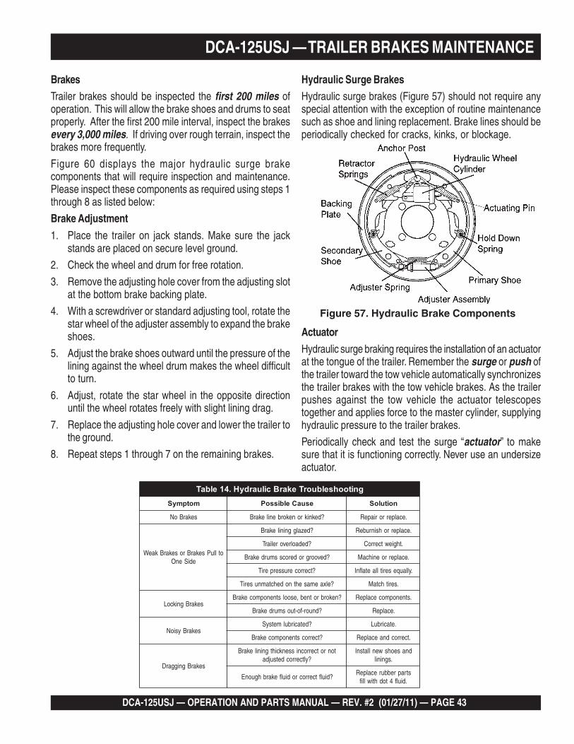
Hydraulic Surge BrakesHydraulic surge brakes (Figure 57) should not require anyspecial attention with the exception of routine maintenancesuch as shoe and lining replacement. Brake lines should beperiodically checked for cracks, kinks, or blockage.
Figure 57. Hydraulic Brake Components
BrakesTrailer brakes should be inspected the first 200 miles ofoperation. This will allow the brake shoes and drums to seatproperly. After the first 200 mile interval, inspect the brakesevery 3,000 miles. If driving over rough terrain, inspect thebrakes more frequently.
Figure 60 displays the major hydraulic surge brakecomponents that will require inspection and maintenance.Please inspect these components as required using steps 1through 8 as listed below:
Brake Adjustment
1. Place the trailer on jack stands. Make sure the jackstands are placed on secure level ground.
2. Check the wheel and drum for free rotation.
3. Remove the adjusting hole cover from the adjusting slotat the bottom brake backing plate.
4. With a screwdriver or standard adjusting tool, rotate thestar wheel of the adjuster assembly to expand the brakeshoes.
5. Adjust the brake shoes outward until the pressure of thelining against the wheel drum makes the wheel difficultto turn.
6. Adjust, rotate the star wheel in the opposite directionuntil the wheel rotates freely with slight lining drag.
7. Replace the adjusting hole cover and lower the trailer tothe ground.
8. Repeat steps 1 through 7 on the remaining brakes.
Actuator
Hydraulic surge braking requires the installation of an actuatorat the tongue of the trailer. Remember the surge or push ofthe trailer toward the tow vehicle automatically synchronizesthe trailer brakes with the tow vehicle brakes. As the trailerpushes against the tow vehicle the actuator telescopestogether and applies force to the master cylinder, supplyinghydraulic pressure to the trailer brakes.
Periodically check and test the surge “actuator” to makesure that it is functioning correctly. Never use an undersizeactuator.
gnitoohselbuorTekarBciluardyH.41elbaTmotpmyS esuaCelbissoP noituloS
sekarBoN ?deknikronekorbenilekarB .ecalperroriapeR
otlluPsekarBrosekarBkaeWediSenO
?dezalggninilekarB .ecalperrohsinrubeR
?dedaolrevoreliarT .thgiewtcerroC
?devoorgroderocssmurdekarB .ecalperroenihcaM
?tcerrocerusserperiT .yllauqeseritllaetalfnI
?elxaemasehtnodehctamnuseriT .serithctaM
sekarBgnikcoL?nekorbrotneb,esoolstnenopmocekarB .stnenopmocecalpeR
?dnuor-fo-tuosmurdekarB .ecalpeR
sekarBysioN?detacirbulmetsyS .etacirbuL
?tcerrocstnenopmocekarB .tcerrocdnaecalpeR
sekarBgniggarD
tonrotcerrocnissenkcihtgninilekarB?yltcerrocdetsujda
dnaseohswenllatsnI.sgninil
?diulftcerrocrodiulfekarbhguonEstraprebburecalpeR
.diulf4todhtiwllif

PAGE 44 — DCA-125USJ — OPERATION AND PARTS MANUAL — REV. #2 (01/27/11)
Tires/Wheels/Lug NutsTires and wheels are a very important and criticalcomponents of the trailer. When specifying or replacing thetrailer wheels it is important the wheels, tires, and axle areproperly matched.
Tire Wear/InflationTire inflation pressure is the most important factor in tire life.Pressure should be checked cold before operation DO NOTbleed air from tires when they are hot!. Check inflationpressure weekly during use to insure the maximum tire lifeand tread wear.
Table 15 (Tire Wear Troubleshooting) will help pinpoint thecauses and solutions of tire wear problems.
SuspensionThe leaf suspension springs and associated components(Figure 58) should be visually inspected every 6,000 milesfor signs of excessive wear, elongation of bolt holes, andloosening of fasteners. Replace all damaged parts(suspension) immediately. Torqued suspension componentsas detailed in Table 16.
Figure 58. Major Suspension Components
DCA-125USJ — TRAILER MAINTENANCE
WEAR PATTERN CAUSE SOLUTION
Center Wear Over Inflation.Adjust pressure toparticular load per tiremanufacturer.
Edge Wear Under Inflation.Adjust pressure toparticular load per tiremanufacturer.
Side Wear Loss of camberor overloading.
Make sure load doesnot exceed axle rating.Align wheels.
Toe Wear Incorrect toe-in. Align wheels.
Cupping Out-of-balance. Check bearing adjustmentand balance tires.
Flat SpotsWheel lockup &tire skidding.
Avoid sudden stops whenpossible and adjust brakes.
TABLE 15. TIRE WEAR TROUBLESHOOTING
stnemeriuqeReuqroTnoisnepsuS.61elbaT
metI ).sbL-.tF(euqroT
TLOB-U"8/3 53-XAM03-NIM
TLOB-U"61/7 06-XAM54-NIM
TLOB-U"2/1 06-XAM54-NIM
SHACKLE BOLT
SPRING EYE BOLT
SNUG FIT ONLY. PARTS MUST ROTATE FREELY.LOCKING NUTS OR COTTER PINS ARE PROVIDED
TO RETAIN NUT-BOLT ASSEMBLY.
SHOULDER TYPE
SHACKLE BOLT05-XAM03-NIM
DO NOT attempt to repair or modify a wheel. DO NOTinstall in inner tube to correct a leak through the rim. If therim is cracked, the air pressure in the innertube may cause pieces of the rim toexplode (break off) with great force andcause serious eye or bodily injury.
CAUTION - REPAIRING TRAILER WHEELS
ALWAYS wear safety glasses whenremoving or installing force fitted parts.Failure to comply may result in seriousinjury.
CAUTION - EYESIGHT HAZARD
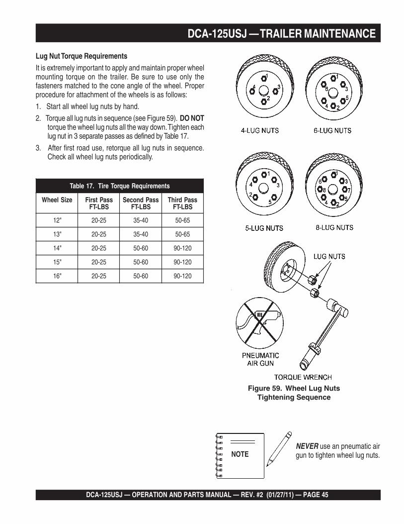
DCA-125USJ — OPERATION AND PARTS MANUAL — REV. #2 (01/27/11) — PAGE 45
1
Lug Nut Torque RequirementsIt is extremely important to apply and maintain proper wheelmounting torque on the trailer. Be sure to use only thefasteners matched to the cone angle of the wheel. Properprocedure for attachment of the wheels is as follows:
1. Start all wheel lug nuts by hand.
2. Torque all lug nuts in sequence (see Figure 59). DO NOTtorque the wheel lug nuts all the way down. Tighten eachlug nut in 3 separate passes as defined by Table 17.
3. After first road use, retorque all lug nuts in sequence.Check all wheel lug nuts periodically.
NEVER use an pneumatic airgun to tighten wheel lug nuts.
Figure 59. Wheel Lug NutsTightening Sequence
DCA-125USJ — TRAILER MAINTENANCE
stnemeriuqeReuqroTeriT.71elbaT
eziSleehW ssaPtsriFSBL-TF
ssaPdnoceSSBL-TF
ssaPdrihTSBL-TF
"21 52-02 04-53 56-05
"31 52-02 04-53 56-05
"41 52-02 06-05 021-09
"51 52-02 06-05 021-09
"61 52-02 06-05 021-09
NOTE

PAGE 46 — DCA-125USJ — OPERATION AND PARTS MANUAL — REV. #2 (01/27/11)
DCA-125USJ — TRAILER WIRING DIAGRAM
Figure 60. Trailer/Towing Vehicle Wiring Diagram

DCA-125USJ — OPERATION AND PARTS MANUAL — REV. #2 (01/27/11) — PAGE 47
1
DCA-125USJ — GENERATOR WIRING DIAGRAM
Figure 61. Generator Wiring Diagram

PAGE 48 — DCA-125USJ — OPERATION AND PARTS MANUAL — REV. #2 (01/27/11)
DCA-125USJ — ENGINE WIRING DIAGRAM
Figure 62. Engine Wiring Diagram
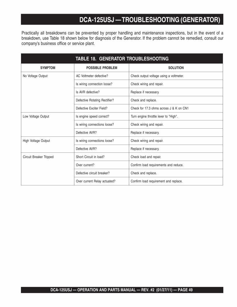
DCA-125USJ — OPERATION AND PARTS MANUAL — REV. #2 (01/27/11) — PAGE 49
1
Practically all breakdowns can be prevented by proper handling and maintenance inspections, but in the event of abreakdown, use Table 18 shown below for diagnosis of the Generator. If the problem cannot be remedied, consult ourcompany's business office or service plant.
DCA-125USJ — TROUBLESHOOTING (GENERATOR)
GNITOOHSELBUORTROTARENEG.81ELBAT
MOTPMYS MELBORPELBISSOP NOITULOS
tuptuOegatloVoN ?evitcefedretemtloVCA .retemtlovagnisuegatlovtuptuokcehC
?esoolnoitcennocgniriwsI .riaperdnagniriwkcehC
?evitcefedRVAsI .yrassecenfiecalpeR
?reifitceRgnitatoRevitcefeD .ecalperdnakcehC
?dleiFreticxEevitcefeD 1NCnoK&Jssorcasmho3.71rofkcehC
tuptuOegatloVwoL ?tcerrocdeepsenignesI ."hgiH"otrevelelttorhtenignenruT
?esoolsnoitcennocgniriwsI .riaperdnagniriwkcehC
?RVAevitcefeD .yrassecenfiecalpeR
tuptuOegatloVhgiH ?esoolsnoitcennocgniriwsI .riaperdnagniriwkcehC
?RVAevitcefeD .yrassecenfiecalpeR
deppirTrekaerBtiucriC ?daolnitiucriCtrohS .riaperdnadaolkcehC
?tnerrucrevO .ecuderdnastnemeriuqerdaolmrifnoC
?rekaerbtiucricevitcefeD .ecalperdnakcehC
?detautcayaleRtnerrucrevO .ecalperdnatnemeriuqerdaolmrifnoC

PAGE 50 — DCA-125USJ — OPERATION AND PARTS MANUAL — REV. #2 (01/27/11)
DCA-125USJ — TROUBLESHOOTING (ENGINE CONTROLLER)
Practically all breakdowns can be prevented by proper handling and maintenance inspections, but in the event of abreakdown, use Table 19 (Engine Controller Troubleshooting) as a basic guideline for troubleshooting the MicroprocessorEngine Controller unit (MPEC). If the problem cannot be remedied, consult our company's business office or service plant.
)CEPM(GNITOOHSELBUORTRELLORTNOCENIGNE.91ELBAT
MOTPMYS MELBORPELBISSOP NOITULOS
sithgilerusserpliowoL.no
?levelliowoL .levelliolliF
?eruliaftinugnidneserusserpliO .tinugnidneserusserplioecalpeR
?rellortnoCninoitnuflamyaledemiT .relaedotrefeR
?detrohseriW .eriwriaper/tcepsnI
sithgilleveltnaloocwoL)dellatsnIyllanoitpO(.no
?leveltnaloocwoL .leveltnalooclliF
?eruliaftinugnidneS .tinugnidnesecalpeR
?egatlovyrettabwoL .yrettabegrahc/ecalpeR
erutrepmettnaloochgiH.nosithgil
?tcerrocninoisnettlebnaF .tlebnafecalper/nethgiT
?rotaidarhguorhtnoitalucrictonsiwolfriA .llirgrotaidarriaper/naelC
?neposrooD .sroodesolC
?gnikaeltsuahxE .trapytluafrosteksagriaper/ecalpeR
?dedaolrevogniebrotareneG .daolecuder/kcehC
?eruliaftatsomrehT .tatsomrehtecalpeR
?dekcolbekatniriA .sekatniriallaraelC
?eruliafhctiwserutarepmeT .hctiwserutarepmetecalpeR
.nosithgilknarcrevO?leuFwolrooN .levelleuflliF
?detarbilacebotsdeenrellortnoC .relaedotrefeR
.nosithgildeepsrevO
?hgihootdeepsenigneMPR .MPRtsujdA
?detsujdaebotsdeenrotautcaronrevoG .rotautcaronrevogtsujdA
?detsujdaebotsdeenrellortnocronrevoG .rellortnocronrevogtsujdA
?detarbilacebotsdeenrellortnoCenignE .relaedotrefeR
ro)s(thgilUPMfossoL.no
?tnemtsujdafotuopukcipcitengaM .pukcipcitengamtsujdA
?ytridpukcipcitengaM .pukcipcitengamnaelC

DCA-125USJ — OPERATION AND PARTS MANUAL — REV. #2 (01/27/11) — PAGE 51
1
NOTE PAGE
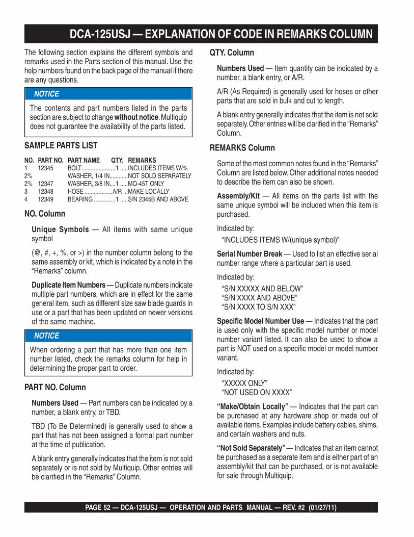
PAGE 52 — DCA-125USJ — OPERATION AND PARTS MANUAL — REV. #2 (01/27/11)
DCA-125USJ — EXPLANATION OF CODE IN REMARKS COLUMNThe following section explains the different symbols and remarks used in the Parts section of this manual. Use the help numbers found on the back page of the manual if there are any questions.
SAMPLE PARTS LIST
NO. PART NO. PART NAME QTY. REMARKS1 12345 BOLT ......................1 .....INCLUDES ITEMS W/%2% WASHER, 1/4 IN. ...........NOT SOLD SEPARATELY2% 12347 WASHER, 3/8 IN. ...1 .....MQ-45T ONLY3 12348 HOSE ..................A/R ...MAKE LOCALLY4 12349 BEARING ..............1 .....S/N 2345B AND ABOVE
NO. Column
Unique Symbols — All items with same unique symbol
(@, #, +, %, or >) in the number column belong to the same assembly or kit, which is indicated by a note in the “Remarks” column.
Duplicate Item Numbers — Duplicate numbers indicate multiple part numbers, which are in effect for the same general item, such as different size saw blade guards in use or a part that has been updated on newer versions of the same machine.
PART NO. Column
Numbers Used — Part numbers can be indicated by a number, a blank entry, or TBD.
TBD (To Be Determined) is generally used to show a part that has not been assigned a formal part number at the time of publication.
A blank entry generally indicates that the item is not sold separately or is not sold by Multiquip. Other entries will be clarified in the “Remarks” Column.
NOTICE
The contents and part numbers listed in the parts section are subject to change without notice. Multiquip does not guarantee the availability of the parts listed.
NOTICE
When ordering a part that has more than one item number listed, check the remarks column for help in determining the proper part to order.
QTY. Column
Numbers Used — Item quantity can be indicated by a number, a blank entry, or A/R.
A/R (As Required) is generally used for hoses or otherparts that are sold in bulk and cut to length.
A blank entry generally indicates that the item is not sold separately. Other entries will be clarified in the “Remarks” Column.
REMARKS Column
Some of the most common notes found in the “Remarks” Column are listed below. Other additional notes needed to describe the item can also be shown.
Assembly/Kit — All items on the parts list with thesame unique symbol will be included when this item is purchased.
Indicated by:“INCLUDES ITEMS W/(unique symbol)”
Serial Number Break — Used to list an effective serial number range where a particular part is used.
Indicated by: “S/N XXXXX AND BELOW”“S/N XXXX AND ABOVE”“S/N XXXX TO S/N XXX”
Specific Model Number Use — Indicates that the part is used only with the specific model number or model number variant listed. It can also be used to show a part is NOT used on a specific model or model number variant.
Indicated by:“XXXXX ONLY”“NOT USED ON XXXX”
“Make/Obtain Locally” — Indicates that the part can be purchased at any hardware shop or made out of available items. Examples include battery cables, shims, and certain washers and nuts.
“Not Sold Separately” — Indicates that an item cannot be purchased as a separate item and is either part of an assembly/kit that can be purchased, or is not available for sale through Multiquip.

DCA-125USJ — OPERATION AND PARTS MANUAL — REV. #2 (01/27/11) — PAGE 53
1
DCA-125USJ — SUGGESTED SPARE PARTS
Part number on this Suggested Spare Partslist may supercede/replace the P/N shownin the text pages of this book.
NOTE
DCA-125USJ W/JOHN DEERE4045TF275 DIESEL ENGINE
1 TO 3 UNITSQty. P/N Description5 .............. 0602041292 ........................FILTER, OIL5 .............. 0602042594 ........................FILTER, FUEL, PRIMARY5 .............. 0602042595 ........................FILTER, FUEL, FINAL3 .............. 0602046377 ........................ELEMENT, AIR1 .............. 0602011493 ........................BELT, FAN1 .............. 0605505070 ........................CAP. FUEL TANK1 .............. 0602122272 ........................UNIT, OIL PRESSURE1 .............. 0602123261 ........................UNIT, WATER TEMPERATURE2 .............. 0601802149 ........................FUSE, 10A1 .............. 0602123282 ........................SENDER, WATER SWITCH (ENGINE SIDE)1 .............. 0602122281 ........................SENDER, OIL SWITCH (ENGINE SIDE)1 .............. 060122272 ..........................UNIT, OIL PRESSURE1 .............. 0602123261 ........................UNIT, WATER TEMPERATURE

PAGE 54 — DCA-125USJ — OPERATION AND PARTS MANUAL — REV. #2 (01/27/11)
DCA-125USJ — GENERATOR ASSY.GENERATOR ASSY.
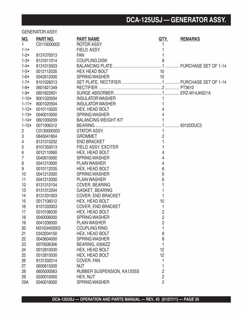
DCA-125USJ — OPERATION AND PARTS MANUAL — REV. #2 (01/27/11) — PAGE 55
1
DCA-125USJ — GENERATOR ASSY.
GENERATOR ASSY.
NO. PART NO. PART NAME QTY. REMARKS1 C0110000002 ROTOR ASSY. 11-1* FIELD ASSY. 11-2* 8131070013 FAN 11-3* 8131611014 COUPLING DISK 81-4* 8131015003 BALANCING PLATE ............................................1 ............. PURCHASE SET OF 1-141-5* 0012112035 HEX HEAD BOLT 101-6* 0042612000 SPRING WASHER 101-7* 8101026013 SET PLATE, RECTIFIER ....................................1 ............. PURCHASE SET OF 1-141-8* 0601821349 RECTIFIER .........................................................2 ............. PT36101-9* 0601822601 SURGE ABSORBER ...........................................1 ............. ERZ-M14JK621A1-10* 8001020004 INSULATOR WASHER 11-11* 8001020504 INSULATOR WASHER 11-12* 0010110020 HEX, HEAD BOLT 41-13* 0040010000 SPRING WASHER 41-14* 0601000209 BALANCING WEIGHT KIT 11-15* 0071906312 BEARING ............................................................1 ............. 6312DDUC32 C0130000503 STATOR ASSY. 13 0845041804 GROMMET 24 8131315202 END BRACKET 15 8101350013 FIELD ASSY. EXCITER 16 0012110060 HEX, HEAD BOLT 47 0042610000 SPRING WASHER 48 0041210000 PLAIN WASHER 49 0010112035 HEX, HEAD BOLT 610 0041212000 SPRING WASHER 611 0041212000 PLAIN WASHER 612 8131310104 COVER, BEARING 113 8131312204 GASKET, BEARING 114 8131331003 COVER, END BRACKET 115 0017106012 HEX, HEAD BOLT 1016 8101333003 COVER, END BRACKET 117 0010106030 HEX, HEAD BOLT 218 0040006000 SPRING WASHER 219 0041206000 PLAIN WASHER 220 M3163400003 COUPLING RING 121 0343204150 HEX, HEAD BOLT 822 0043604000 SPRING WASHER 823 0070506306 BEARING, 6306ZZ 124 0012810030 HEX, HEAD BOLT 1225 0012810030 HEX, HEAD BOLT 1226 8131332014 COVER, FAN 127 0600815000 NUT 128 0605000063 RUBBER SUSPENSION, KA120SS 229 0030016000 HEX, NUT 229A 0040016000 SPRING WASHER 2
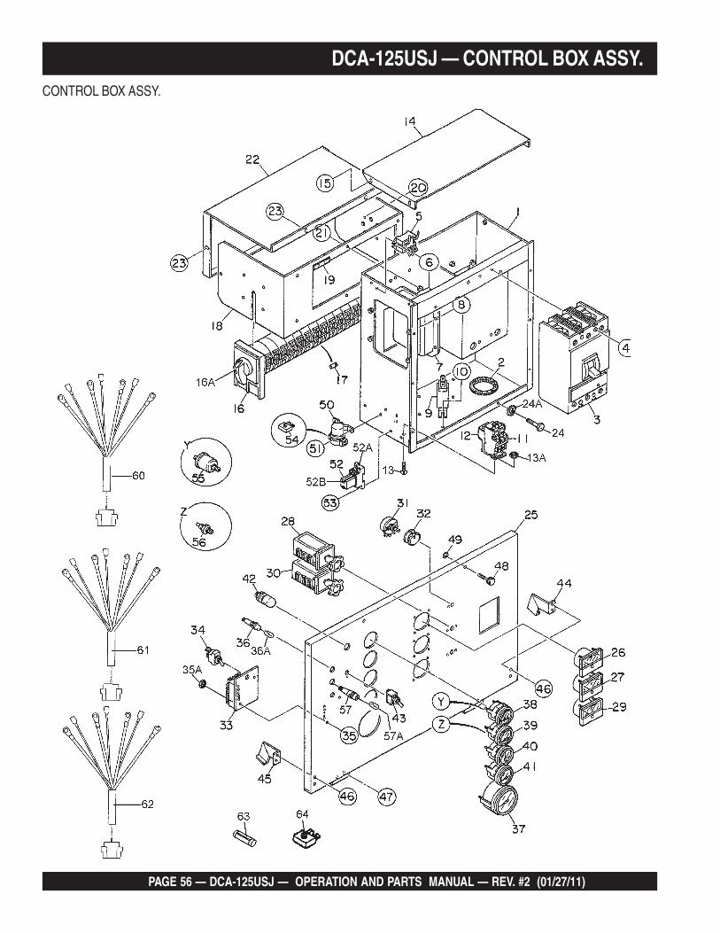
PAGE 56 — DCA-125USJ — OPERATION AND PARTS MANUAL — REV. #2 (01/27/11)
DCA-125USJ — CONTROL BOX ASSY.CONTROL BOX ASSY.

DCA-125USJ — OPERATION AND PARTS MANUAL — REV. #2 (01/27/11) — PAGE 57
1
DCA-125USJ — CONTROL BOX ASSY.CONTROL BOX ASSY.
NO. PART NO. PART NAME QTY. REMARKS1 M3213000702 CONTROL BOX 12 0330000180 EDGING 23 0601808823 CIRCUIT BREAKER, 300A ............................... 1 ........... LAF3630010393P4 0021006080 MACHINE SCREW 45 0601823863 RELAY UNIT ..................................................... 2 ........... MSA9013A6 0027104016 MACHINE SCREW 47 0601820671 AUTOMATIC VOLTAGE REGULATOR................ 1 ........... NTA-5A-2DB8 0027105016 MACHINE SCREW 49 0601806118 CURRENT TRANSFORMER ............................. 3 ........... 814-943 200/5A10 0027106016 MACHINE SCREW 611 0601820845 OVER CURRENT RELAY .................................. 1 ........... LR2D130812 0601820846 OVER CURRENT RELAY .................................. 1 ........... LA7D106413 0027104016 MACHINE SCREW 213A 0207004000 HEX, NUT 214 M3213500013 CONTROL BOX COVER 115 0016906016 HEX, HEAD BOLT 416 M3270100104 SELECTOR SWITCH ........................................ 1 ........... XUSS0157416A 047230402 KNOB, SELECTOR SWITCH 117 M3276600004 SPACER 818 M3213600503 SWITCH BRACKET 119 03300003330 EDGING 220 0027104010 MACHINE SCREW 421 0016906016 HEX, HEAD BOLT 622 M3213600604 SWITCH COVER 123 0016906016 HEX, HEAD BOLT 424 0016906016 HEX, HEAD BOLT 1024A 0040506000 TOOTHED WASHER 125 M3223000503 CONTROL PANEL 126 0601807641 FREQUENCY METER ...................................... 1 ........... FCF-6 45~65Hz 240V27 0601808988 AC AMMETER .................................................. 1 ........... ACF-6 0~200A/400A:5A28 0601801040 CHANGE-OVER SWITCH, AMMETER ............. 1 ........... SL-2AS29 0601806859 AC VOLTMETER ............................................... 1 ........... SCF-6 0~600V30 0601801041 CHANGE-OVER SWITCH, VOLTMETER .......... 1 ........... SL-2VS
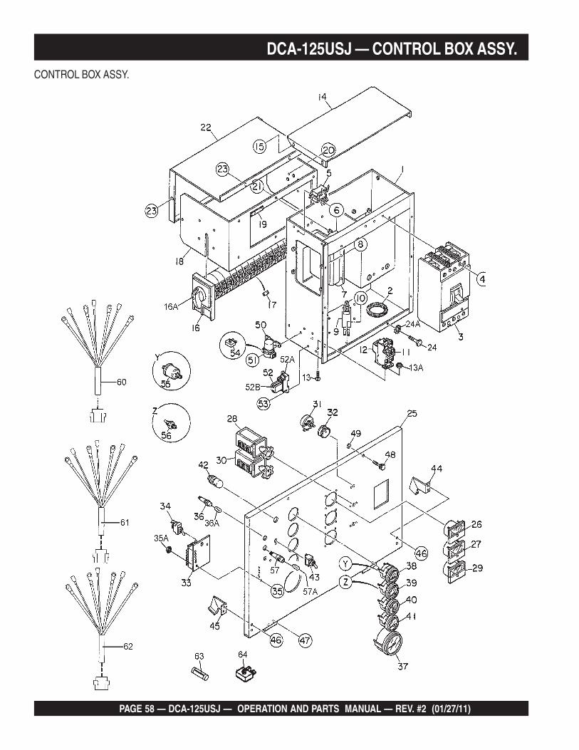
PAGE 58 — DCA-125USJ — OPERATION AND PARTS MANUAL — REV. #2 (01/27/11)
CONTROL BOX ASSY.
DCA-125USJ — CONTROL BOX ASSY.

DCA-125USJ — OPERATION AND PARTS MANUAL — REV. #2 (01/27/11) — PAGE 59
1
CONTROL BOX ASSY.
NO. PART NO. PART NAME QTY. REMARKS31 0601840073 RHEOSTAT (VOLTAGE REGULATOR) ............... 1 ........... RA20A2SE102BJ 2W 1k OHM32 0601840121 KNOB 133 ECU9988NJD CONTROLLER .................................................. 1 ........... REPLACES 060220259334 0601831340 SWITCH ............................................................ 1 ........... 7562K435 0027104040 MACHINE SCREW 235A 0207004000 HEX, NUT 236 0602103092 PREHEAT LAMP ............................................... 1 ........... PL-0536A 0601810245 BULB 137 0602120096 TACHOMETER .................................................. 1 ........... 11181238 0602122093 OIL PRESSURE GAUGE .................................. 1 ........... 10017439 0602123092 WATER TEMPERATURE GAUGE ..................... 1 ........... 10018240 0602121080 CHARGING AMMETER .................................... 1 ........... 10015841 0602125090 FUEL GAUGE.................................................... 1 ........... 10017642 0601810141 PANEL LIGHT.................................................... 1 ........... 882680037043 0601831330 SWITCH, PANEL LIGHT ................................... 1 ........... 90-000144 M1223100004 STOPPER 145 M3223100004 STOPPER 146 0027105010 MACHINE SCREW 447 0027105010 MACHINE SCREW 448 M9220100004 SET SCREW 249 0080200007 SNAP RING 250 0602202592 STARTER RELAY .............................................. 1 ........... AT14101151 0027106018 MACHINE SCREW 252 LY2DDC12V RELAY 152A PTF08A BASE 152B PYCA1 CLIP 253 0027104020 MACHINE SCREW 254 0601823240 RECTIFIER ....................................................... 1 ........... DE450357 0602122272 UNIT, OIL PRESSURE ...................................... 1 ........... 10849757A M9200100004 ADAPTOR 158 0602123261 UNIT, WATER TEMPERATURE ......................... 1 ........... 02025-0058A 0602021109 PACKING 160 M3246701904 WIRE HARNESS, GENERATOR 161 M3357201102 WIRE HARNESS, ENGINE 162 M3357200304 WIRE HARNESS, FUEL LEAK ......................... 1 ........... 8400041~63 0601802149 FUSE ................................................................. 2 ........... F-106510A64 0601823240 RECTIFIER ....................................................... 1 ........... DE450365 0602103092 ALARM LAMP, PL095 ........................................ 1 ........... 8400041~65A 0601810245 BULB ................................................................. 1 ........... 8400041~
DCA-125USJ — CONTROL BOX ASSY.

PAGE 60 — DCA-125USJ — OPERATION AND PARTS MANUAL — REV. #2 (01/27/11)
DCA-125USJ — ENGINE AND RADIATOR ASSY.ENGINE AND RADIATOR ASSY.

DCA-125USJ — OPERATION AND PARTS MANUAL — REV. #2 (01/27/11) — PAGE 61
1
ENGINE AND RADIATOR ASSY.
NO. PART NO. PART NAME QTY. REMARKS1 M3923200054 ENGINE & RADIATOR SET ................................. 1 ........ JOHN DEERE 6068TF2751-1 0602041292 CARTRIDGE, OIL FILTER .................................... 1 ........ RE5048361-2 0602042594 CARTRIDGE, PRIMARY, FUEL FILTER ...............1 ........ RE5171811-3 0602042595 CARTRIDGE, FINAL, FUEL FILTER .................... 1 ........ RE5090311-4 0602011493 FAN BELT ............................................................. 1 ........ 24022 0602060003 BLOWER FAN ...................................................... 1 ........ AT392473 0602061000 FAN SPACER ....................................................... 1 ........ R819114 0012110095 HEX, HEAD BOLT 45 0042510000 SPRING WASHER 46 M2303200303 ENGINE FOOT 27 0010312030 HEX, HEAD BOLT 68 0040012000 SPRING WASHER 69 0605000060 RUBBER SUSPENSION 210 0030012000 HEX, NUT 211 0040012000 SPRING WASHER 212 C0923200124 RADIATOR 112A 0602011062 CAP, RADIATOR 113 M9200100904 PLUG 114 0150000016 O RING 115 M3131300103 FAN BRACKET 116 0016910025 HEX, HEAD BOLT 617 0016910025 HEX, HEAD BOLT 418 M3310500813 RADIATOR HOSE 119 M3310500903 RADIATOR HOSE 120 0605515148 HOSE BAND 321 0605515147 HOSE BAND 122 0601822794 FAN MOTOR 223 0017110035 HEX, HEAD BOLT 824 0602046258 AIR CLEANER .....................................................1 ........ FRG10029724A 0602046377 ELEMENT, AIR CLEANER ................................... 1 ........ P77821425 0602040650 INDICATOR, AIR CLEANER ................................. 1 ........ RBXO0-225226 0602040596 BAND, AIR CLEANER 227 0016908020 HEX, HEAD BOLT 428 0207008000 HEX, NUT 429 M3373100003 HOSE, AIR CLEANER 130 0605515146 HOSE BAND 1
DCA-125USJ — ENGINE AND RADIATOR ASSY.

PAGE 62 — DCA-125USJ — OPERATION AND PARTS MANUAL — REV. #2 (01/27/11)
DCA-125USJ — ENGINE AND RADIATOR ASSY.ENGINE & RADIATOR ASSY.

DCA-125USJ — OPERATION AND PARTS MANUAL — REV. #2 (01/27/11) — PAGE 63
1
DCA-125USJ — ENGINE AND RADIATOR ASSY.
ENGINE & RADIATOR ASSY.
NO. PART NO. PART NAME QTY. REMARKS31 0605515197 HOSE BAND 132 0602022563 ADAPTER 133 0602022561 90 DEGREE ELBOW 134 0603306590 CONNECTOR 135 0603300285 ROCKNUT 136 0605511395 VALVE 137 0603306395 HOSE JOINT 138 0602021070 CAP 139 0269200450 DRAIN HOSE 140 M9300000203 RESERVE TANK 141 0602010900 CAP, RESERVE TANK 142 M3316100303 BRACKET, RESERVE TANK 143 0016908020 HEX, HEAD BOLT 344 0199102200 HOSE 145 0193600700 HOSE 146 0193601000 HOSE 147 0605515106 HOSE BAND 348 M3326000204 BLOWBY HOSE 149 0605515149 HOSE BAND 150 M3260600104 RELAY BRACKET 152 0602202592 RELAY ............................................................... 1 ........... AT14101153 0027106016 MACHINE SCREW 254 0030006000 HEX, NUT 255 0017112025 HEX, HEAD BOLT 156 0040512000 TOOTHED WASHER 157 0602122281 SENDER, OIL PRESSURE 158 0602123282 SENDER, WATER PRESSURE 1

PAGE 64 — DCA-125USJ — OPERATION AND PARTS MANUAL — REV. #2 (01/27/11)
DCA-125USJ — OUTPUT TERMINAL ASSY.OUTPUT TERMINAL ASSY.

DCA-125USJ — OPERATION AND PARTS MANUAL — REV. #2 (01/27/11) — PAGE 65
1
DCA-125USJ — OUTPUT TERMINAL ASSY.OUTPUT TERMINAL ASSY.
NO. PART NO. PART NAME QTY. REMARKS1 M3230700003 TERMINAL PANEL 12 M9220100304 OUTPUT TERMINAL BOLT 53 M9220100404 TIE BOLT 54 0039316000 HEX, NUT 105 0040016000 SPRING WASHER 156 0041416000 PLAIN WASHER 207 0016908035 HEX, HEAD BOLT 58 M3236100503 TERMINAL COVER 19 M3236100404 OUTPUT WINDOW 110 0605010040 HINGE 211 0027103010 MACHINE SCREW 411A 0030003000 HEX, NUT 411B 0041203000 PLAIN WASHER 412 0027103010 MACHINE SCREW 412A 0030003000 HEX, NUT 413 0016906020 HEX, HEAD BOLT 214 0016906016 HEX, HEAD BOLT 415 M3236400004 CABLE OUTLET COVER 116 M3236300004 SUPPORTER, CABLE OUTLET COVER 117 0016906020 HEX, HEAD BOLT 618 0601808803 CIRCUIT BREAKER, 1-POLE 20A .................... 2 ........... QOU 120B19 0601808804 CIRCUIT BREAKER, 2-POLE 50A .................... 3 ........... QOU 250B20 M1260700304 BREAKER FITTING COVER 120A 022100150 CUSHION RUBBER 121 0016906020 HEX, HEAD BOLT 222 0601812598 RECEPTACLE ................................................... 2 ........... GF530EM 125V 20A X 223 0601812538 RECEPTACLE ................................................... 3 ........... CS6369 250V 50A24 0027104016 MACHINE SCREW 1024A 0207004000 HEX, NUT 1025 M3236100213 TERMINAL COVER 126 0010112045 HEX, HEAD BOLT 227 0041212000 PLAIN WASHER 228 M9310200004 STAY RUBBER 229 0030012000 HEX, NUT 230 0603306775 BLIND PLUG 231 0027104016 MACHINE SCREW 432 0601815194 TERMINAL 133 0027104016 MACHINE SCREW 2
THE SERIAL NUMBER MAY BE REQUIRED.
ADD THE FOLLOWING DIGITS AFTER THE PART NUMBERWHEN ORDERING ANY PAINTED PANEL TO INDICATECOLOR OF UNIT:
1-ORANGE 5-BLACK2-WHITE 6-CATERPILLAR YELLOW3-SPECTRUM GREY 7-CATO GOLD4-SUNBELT GREEN 8-RED

PAGE 66 — DCA-125USJ — OPERATION AND PARTS MANUAL — REV. #2 (01/27/11)
DCA-125USJ — BATTERY ASSY.
BATTERY ASSY.

DCA-125USJ — OPERATION AND PARTS MANUAL — REV. #2 (01/27/11) — PAGE 67
1
DCA-125USJ — BATTERY ASSY.BATTERY ASSY.
NO. PART NO. PART NAME QTY. REMARKS1 0602220196 BATTERY ....................................................... 1 ............. 4D-22 M9310500404 BATTERY SHEET 13 M9103000504 BATTERY BAND 14 0602220921 BATTERY BOLT SET 25 M3346900904 BATTERY CABLE 16 M3346901004 BATTERY CABLE 17 CABLE ........................................................... 1 ............. MAKE LOCALLY8 0030012000 HEX, NUT 18A 0040012000 SPRING WASHER 19 0017112025 HEX, HEAD BOLT 19A 0040512000 TOOTHED WASHER 110 0040520000 TOOTHED WASHER 1
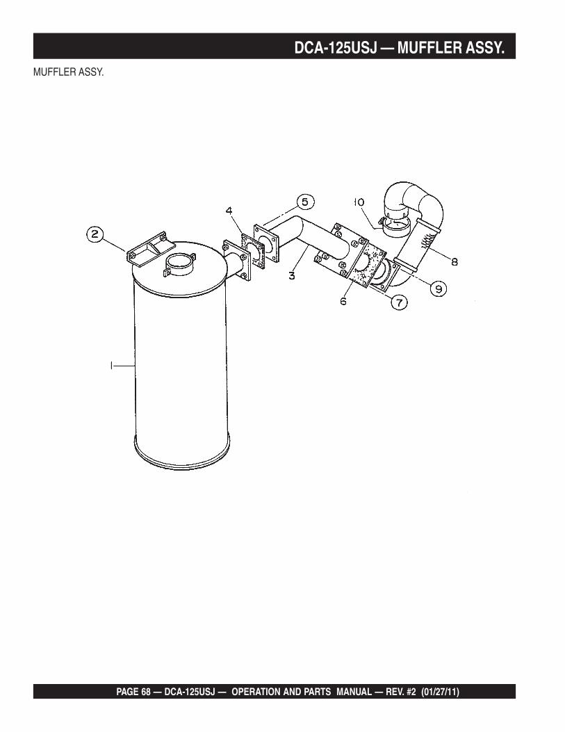
PAGE 68 — DCA-125USJ — OPERATION AND PARTS MANUAL — REV. #2 (01/27/11)
DCA-125USJ — MUFFLER ASSY.MUFFLER ASSY.

DCA-125USJ — OPERATION AND PARTS MANUAL — REV. #2 (01/27/11) — PAGE 69
1
DCA-125USJ — MUFFLER ASSY.MUFFLER ASSY.
NO. PART NO. PART NAME QTY. REMARKS1 M3330100402 MUFFLER 12 0017112030 HEX, HEAD BOLT 43 M3333000903 EXHAUST PIPE 14 M3333200304 GASKET 15 0017110040 HEX, HEAD BOLT 46 M3333200204 GASKET 17 0017108040 HEX, HEAD BOLT 47 0017110035 HEX, HEAD BOLT ............................................. 4 ........... S/N 8500015~8 M3333000803 EXHAUST PIPE 19 0016908055 HEX, HEAD BOLT 49 0017110050 HEX, HEAD BOLT ............................................. 4 ........... S/N 8500015~10 0602325066 CLAMP 1
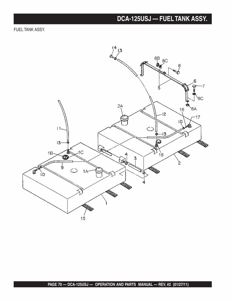
PAGE 70 — DCA-125USJ — OPERATION AND PARTS MANUAL — REV. #2 (01/27/11)
DCA-125USJ — FUEL TANK ASSY.FUEL TANK ASSY.

DCA-125USJ — OPERATION AND PARTS MANUAL — REV. #2 (01/27/11) — PAGE 71
1
DCA-125USJ — FUEL TANK ASSY.
FUEL TANK ASSY.
NO. PART NO. PART NAME QTY. REMARKS1 M3363001402 FUEL TANK 11A 0605505070 FUEL TANK CAP 11B 0605501074 FUEL SENDER UNIT 11C 0605516090 GASKET 12 M3363001504 FUEL TANK 12A 0605505070 FUEL TANK CAP 13 0191700260 CONNECT HOSE 24 0605515149 HOSE BAND 45 M3363200404 TANK BAND 86 M9310500104 SUPPORTER SHEET 87 0016908020 HEX, HEAD BOLT 88 0016908055 HEX, HEAD BOLT 48A 0030008000 HEX, NUT 88B 0207308000 HEX, NUT 48C 0041208000 PLAIN WASHER 129 0191302500 VENT HOSE 110 0605515109 HOSE BAND 211 0191301200 SUCTION HOSE 112 0191301200 RETURN HOSE 113 0605515109 HOSE BAND 414 0602042601 RETURN PIPE .................................................. 1 ........... RE6705015 0222101000 TANK SHEET 616 0605512190 HOSE JOINT 117 0605511190 PICKUP ELBOW 118 0605512191 HOSE JOINT 1/4-18 NPT 1

PAGE 72 — DCA-125USJ — OPERATION AND PARTS MANUAL — REV. #2 (01/27/11)
DCA-125USJ — ENCLOSURE #1 ASSY.ENCLOSURE #1 ASSY.
THE SERIAL NUMBER MAY BE REQUIRED.
ADD THE FOLLOWING DIGITS AFTER THE PARTNUMBER WHEN ORDERING ANY PAINTED PANEL TOINDICATE COLOR OF UNIT:
1-ORANGE 5-BLACK2-WHITE 6-CATERPILLAR YELLOW3-SPECTRUM GREY 7-CATO GOLD4-SUNBELT GREEN 8-RED

DCA-125USJ — OPERATION AND PARTS MANUAL — REV. #2 (01/27/11) — PAGE 73
1
DCA-125USJ — ENCLOSURE #1 ASSY.ENCLOSURE #1 ASSY.
NO. PART NO. PART NAME QTY. REMARKS1 M3413001812 BASE 12 M3363300303 ENVIRONMENTAL TANK 13 0016910030 HEX, HEAD BOLT 124 0603306797 PLUG 15 M3423001202 FRONT FRAME................................................. 1 ........... S/N 8500001 TO 85000405 M3423001602 FRONT FRAME................................................. 1 ........... S/N 8500041~5A M3493107813 ACOUSTIC SHEET ........................................... 1 ........... S/N 8500001 TO 85000355A M3493107823 ACOUSTIC SHEET ........................................... 1 ........... S/N 8500036 TO 84000405A M3493111303 ACOUSTIC SHEET ........................................... 1 ........... S/N 8500041~6 M3423001302 FRONT FRAME................................................. 1 ........... S/N 8500001 TO 85000406 M3423001702 FRONT FRAME................................................. 1 ........... S/N 8500041~6A M3493107813 ACOUSTIC SHEET ........................................... 1 ........... S/N 8500001 TO 85000356A M3493107823 ACOUSTIC SHEET ........................................... 1 ........... S/N 8500036 TO 85000406A M3493111303 ACOUSTIC SHEET ........................................... 1 ........... S/N 8500041~7 0601851739 GROMMET ........................................................ 1 ........... S/N 8500036 TO 85000408 0601850100 GROMMET ........................................................ 1 ...........9 0016908020 HEX, HEAD BOLT 2610 0016910025 HEX, HEAD BOLT 611 M3131400203 HOSE COVER ................................................... 1 ........... S/N 8500001 TO 850004011A M3131400103 HOSE COVER ................................................... 1 ........... S/N 8500041~11B M3131400004 HOSE COVER ................................................... 1 ........... S/N 8500041~12 0016908020 HEX, HEAD BOLT ............................................. 4 ........... S/N 8500001 TO 850004012 0016906020 HEX, HEAD BOLT ........................................... 13 ........... S/N 8500041~13 M3423500104 BRACKET 114 0016906016 HEX, HEAD BOLT 615 M3423200704 DUCT COVER 216 0016906020 HEX, HEAD BOLT 1417 M3423200804 DUCT COVER 118 0016906016 HEX, HEAD BOLT 619 M3310300104 FAN SHROUD 120 M3310300004 FAN SHROUD 121 0016906020 HEX, HEAD BOLT 1422 M3423201003 COVER, FRONT FRAME .................................. 1 ........... S/N 8500001 TO 850003522 M3423201203 COVER, FRONT FRAME .................................. 1 ........... S/N 8500036 TO 850032222 M3423201703 COVER, FRONT FRAME .................................. 1 ........... S/N 8500323 ~22A M3493107904 ACOUSTIC SHEET 123 0016908020 HEX, HEAD BOLT ........................................... 26 ........... S/N 8500001 TO 850004023 0019208020 HEX, HEAD BOLT ........................................... 26 ........... S/N 8500041~24 M3433000803 CENTER FRAME .............................................. 1 ........... S/N 8500001 TO 850003524 M3433000813 CENTER FRAME .............................................. 1 ........... S/N 8500036~

PAGE 74 — DCA-125USJ — OPERATION AND PARTS MANUAL — REV. #2 (01/27/11)
DCA-125USJ — ENCLOSURE #1 ASSY.ENCLOSURE #1 ASSY.
THE SERIAL NUMBER MAY BE REQUIRED.
ADD THE FOLLOWING DIGITS AFTER THE PARTNUMBER WHEN ORDERING ANY PAINTED PANEL TOINDICATE COLOR OF UNIT:
1-ORANGE 5-BLACK2-WHITE 6-CATERPILLAR YELLOW3-SPECTRUM GREY 7-CATO GOLD4-SUNBELT GREEN 8-RED

DCA-125USJ — OPERATION AND PARTS MANUAL — REV. #2 (01/27/11) — PAGE 75
1
ENCLOSURE #1 ASSY.
NO. PART NO. PART NAME QTY. REMARKS24A M3493200614 ACOUSTIC SHEET ........................................... 1 ........... S/N 8500001 TO 850004024A M3493201204 ACOUSTIC SHEET ........................................... 1 ........... S/N 8500041~25 0010114040 HEX, HEAD BOLT 425A 0030014000 HEX, NUT 425B 0040014000 SPRING WASHER 425C 0041214000 PLAIN WASHER 826 0010120050 HEX, HEAD BOLT 426A 0030020000 HEX, NUT 426B 0040020000 SPRING WASHER 426C 0041220000 PLAIN WASHER 827 M3463100802 ROOF PANEL 127A M3493503914 ACOUSTIC SHEET 128 M3463200502 ROOF PANEL 128A M3493504003 ACOUSTIC SHEET 129 M3463200704 BACK PLATE 130 0016906016 HEX, HEAD BOLT 631 M3463200803 DUCT 131A M3493504104 ACOUSTIC SHEET 132 0016908020 HEX, HEAD BOLT 833 M3463400003 DUCT COVER 134 0016908020 HEX, HEAD BOLT 635 M3423200604 OVER COVER, FRONT FRAME 135A M3493108004 ACOUSTIC SHEET 136 0016908020 HEX, HEAD BOLT ........................................... 49 ........... S/N 8500001 TO 850004036 0019208020 HEX, HEAD BOLT ........................................... 49 ........... S/N 8500041~37 0016910025 HEX, HEAD BOLT ............................................. 8 ........... S/N 8500001 TO 850004037 0019210025 HEX, HEAD BOLT ............................................. 8 ........... S/N 8500041~38 M3310600004 COVER, RADIATOR CAP 139 0016908020 HEX, HEAD BOLT 440 0016908020 HEX, HEAD BOLT 641 M3483100004 COVER, EXHAUST PIPE 142 0016908020 HEX, HEAD BOLT ............................................. 2 ........... S/N 8500001 TO 850004043 0016908020 HEX, HEAD BOLT ............................................. 1 ........... S/N 8500041~43A 0040508000 TOOTHED WASHER 144 0016906016 HEX, HEAD BOLT ............................................. 2 ........... S/N 8500001 TO 850003545 0605503062 FUEL LEAK DETECTION SWITCH .................. 1 ........... S/N 840003~46 M1414800104 BRACKET ......................................................... 1 ........... S/N 840003~47 0017108020 HEX HEAD BOLT .............................................. 2 ........... S/N 840003~
DCA-125USJ — ENCLOSURE #1 ASSY.
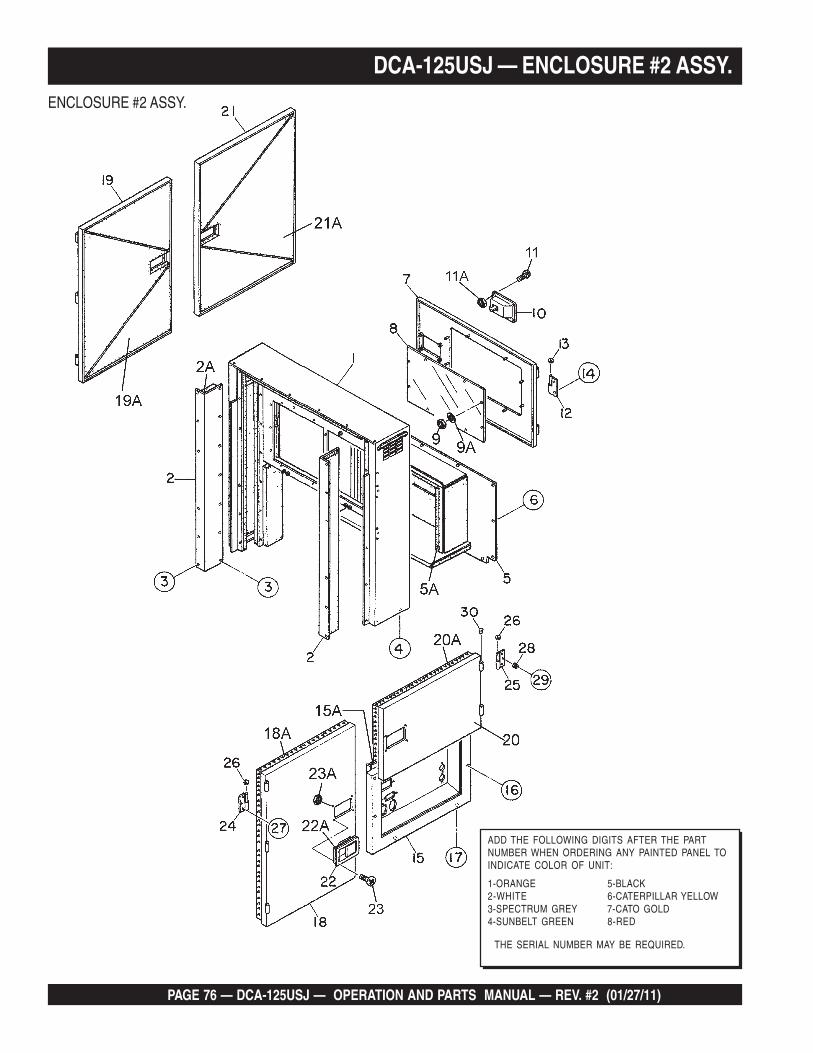
PAGE 76 — DCA-125USJ — OPERATION AND PARTS MANUAL — REV. #2 (01/27/11)
DCA-125USJ — ENCLOSURE #2 ASSY.ENCLOSURE #2 ASSY.
THE SERIAL NUMBER MAY BE REQUIRED.
ADD THE FOLLOWING DIGITS AFTER THE PARTNUMBER WHEN ORDERING ANY PAINTED PANEL TOINDICATE COLOR OF UNIT:
1-ORANGE 5-BLACK2-WHITE 6-CATERPILLAR YELLOW3-SPECTRUM GREY 7-CATO GOLD4-SUNBELT GREEN 8-RED

DCA-125USJ — OPERATION AND PARTS MANUAL — REV. #2 (01/27/11) — PAGE 77
1
DCA-125USJ — ENCLOSURE #2 ASSY.ENCLOSURE #2 ASSY.
NO. PART NO. PART NAME QTY. REMARKS1 M3443000802 REAR FRAME ................................................... 1 ........... S/N 8500001 TO 85000351 M3443000812 REAR FRAME ................................................... 1 ........... S/N 8500036~1A M3493303203 ACOUSTIC SHEET 12 M3443000904 DUCT ................................................................. 2 ........... S/N 8500001 TO 85000352 M3443000914 DUCT ................................................................. 2 ........... S/N 8500036~2A M3493303304 ACOUSTIC SHEET 23 0016908020 HEX, HEAD BOLT 264 0016910025 HEX, HEAD BOLT 45 M3443301003 COVER, REAR FRAME 15A M3493303404 ACOUSTIC SHEET 16 0016908020 HEX, HEAD BOLT 137 M3443200503 DOOR, REAR FRAME 18 M3443600304 WINDOW PLATE 19 0207306000 HEX, NUT 89A 0041206000 PLAIN WASHER 810 M9113000002 DOOR HANDLE ASSY. 111 0021806016 MACHINE SCREW 411A 0030006000 HEX, NUT 412 M9110100204 HINGE 213 M9116100004 WASHER 214 0016908020 HEX, HEAD BOLT 315 M3453200802 SPLASHER PANEL ........................................... 1 ........... S/N 8500001 TO 850003515 M3453200812 SPLASHER PANEL ........................................... 1 ........... S/N 8500036~15A M3493417004 ACOUSTIC SHEET ........................................... 1 ........... S/N 8500001 TO 850003515A M3493417014 ACOUSTIC SHEET ........................................... 1 ........... S/N 8500036~16 0016908065 HEX, HEAD BOLT ............................................. 4 ........... S/N 8500001 TO 850004017 0016910025 HEX, HEAD BOLT ............................................. 2 ........... S/N 8500041~18 M3453002503 SIDE DOOR 118A M3493416804 ACOUSTIC SHEET 119 M3453002603 SIDE DOOR 119A M3493416904 ACOUSTIC SHEET 120 M3453002703 SIDE DOOR 120A M3493417204 ACOUSTIC SHEET 121 M3453002803 SIDE DOOR 121A M3493417104 ACOUSTIC SHEET 122 M9113000002 DOOR HANDLE ASSY. 422A C9312500004 SEAL RUBBER 423 0021806016 MACHINE SCREW 1623A 0030006000 HEX, NUT 1624 M9110100804 HINGE 625 M9110100904 HINGE 526 M9116100004 WASHER 1127 0016908020 HEX, HEAD BOLT ........................................... 26 ........... S/N 8500001 TO 850004027 0019208020 HEX, HEAD BOLT ........................................... 26 ........... S/N 8500041~28 0601850097 STOPPER 829 0027208025 MACHINE SCREW 830 M9310000004 CAP 13
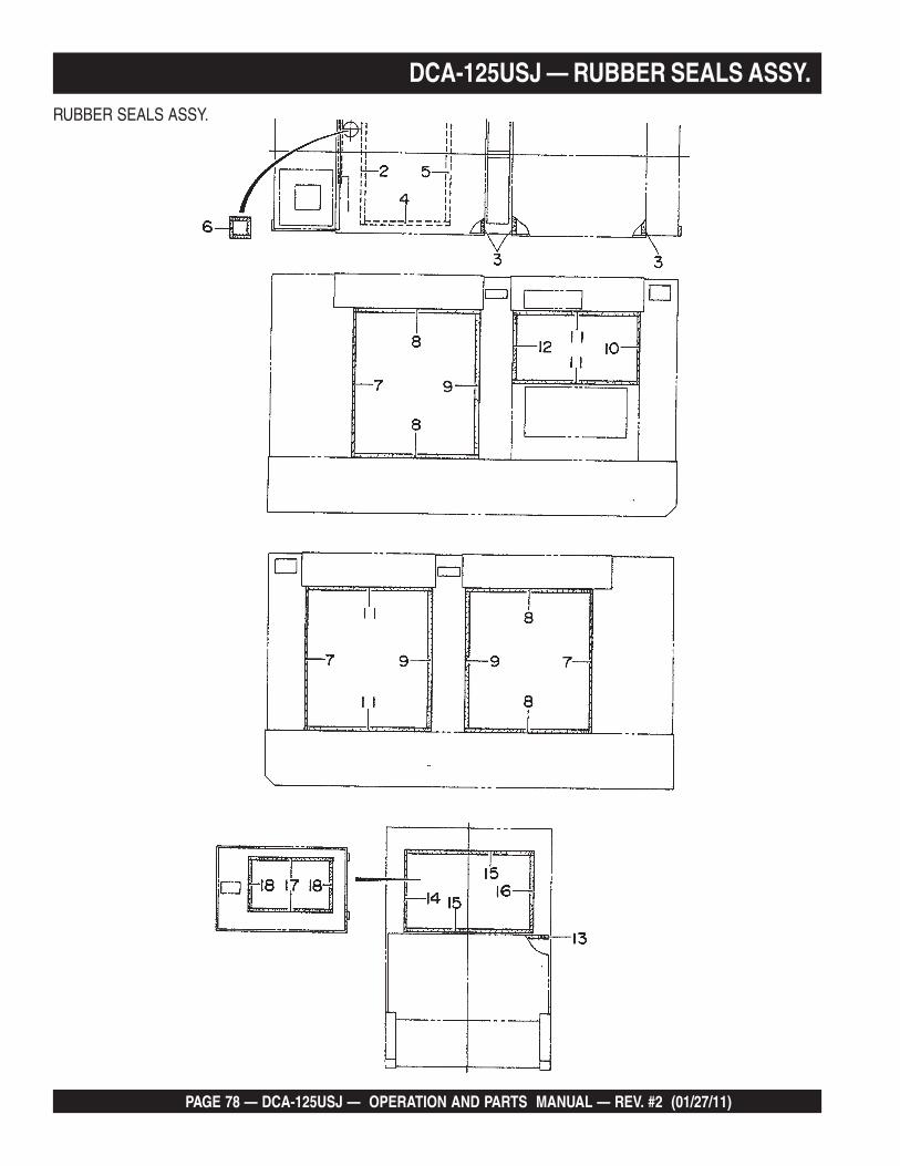
PAGE 78 — DCA-125USJ — OPERATION AND PARTS MANUAL — REV. #2 (01/27/11)
DCA-125USJ — RUBBER SEALS ASSY.RUBBER SEALS ASSY.
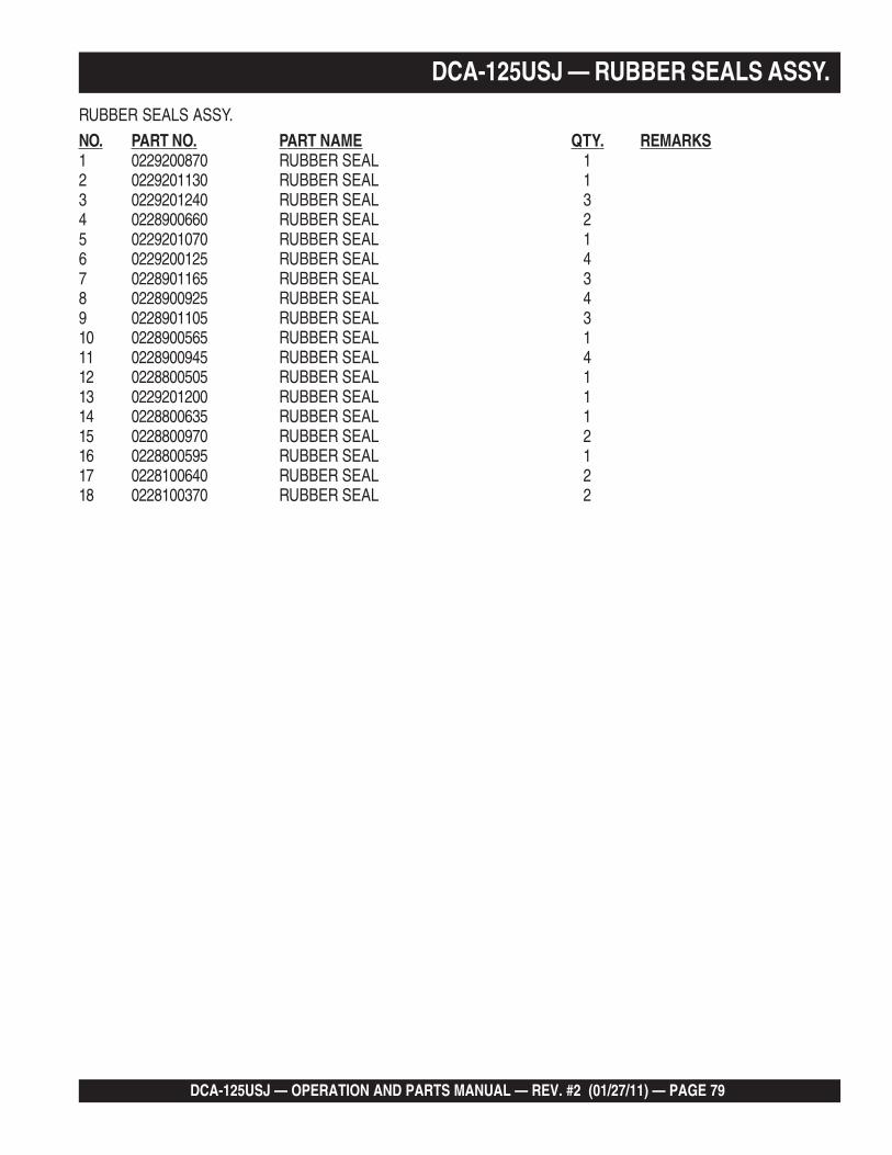
DCA-125USJ — OPERATION AND PARTS MANUAL — REV. #2 (01/27/11) — PAGE 79
1
DCA-125USJ — RUBBER SEALS ASSY.
RUBBER SEALS ASSY.
NO. PART NO. PART NAME QTY. REMARKS1 0229200870 RUBBER SEAL 12 0229201130 RUBBER SEAL 13 0229201240 RUBBER SEAL 34 0228900660 RUBBER SEAL 25 0229201070 RUBBER SEAL 16 0229200125 RUBBER SEAL 47 0228901165 RUBBER SEAL 38 0228900925 RUBBER SEAL 49 0228901105 RUBBER SEAL 310 0228900565 RUBBER SEAL 111 0228900945 RUBBER SEAL 412 0228800505 RUBBER SEAL 113 0229201200 RUBBER SEAL 114 0228800635 RUBBER SEAL 115 0228800970 RUBBER SEAL 216 0228800595 RUBBER SEAL 117 0228100640 RUBBER SEAL 218 0228100370 RUBBER SEAL 2

PAGE 80 — DCA-125USJ — OPERATION AND PARTS MANUAL — REV. #2 (01/27/11)
DCA-125USJ — NAMEPLATE AND DECALS ASSY.NAMEPLATE AND DECALS ASSY.

DCA-125USJ — OPERATION AND PARTS MANUAL — REV. #2 (01/27/11) — PAGE 81
1
DCA-125USJ — NAMEPLATE AND DECALS ASSY.NAMEPLATE AND DECALS ASSY.
NO. PART NO. PART NAME QTY. REMARKS1 M1550000204 DECAL, NOTE ................................................... 1 ........... M150000202 M1550000703 DECAL, AUXILARY OUTPUT............................ 1 ........... M150000703 M3550000004 DECAL, NOTE ................................................... 1 ........... M350000004 M3550001603 DECAL, GENERATOR CONTROL ..................... 1 ........... M350001605 M3550001703 DECAL, ENGINE OPERATING, M35000170 ..... 1 ........... S/N 8500001 TO 85000405 M3550002003 DECAL, ENGINE OPERATING, M35000200 ..... 1 ........... S/N 8500041~6 M3550001803 DECAL, OPERATING PROCEDURES .............. 1 ........... M35000180A7 M9500000004 DECAL, OIL DRAIN PLUG ................................ 1 ........... M900000008 M9500100004 DECAL, WATER................................................. 1 ........... M900100009 M9500300004 DECAL, NEGATIVE........................................... 1 ........... M9003000010 M9500300104 DECAL, POSITIVE ........................................... 1 ........... M9003001011 M9500500004 DECAL, DIESEL FUEL ..................................... 1 ........... M9005000012 M9503000004 DECAL, WARNING MOVING PARTS ................ 2 ........... M9030000013 M9503000103 DECAL, WATER OIL CHECK ............................ 1 ........... M9030001014 M9503100004 DECAL, WARNING HOT COOLANT .................. 1 ........... M9031000015 M9503200004 DECAL, WARNING ENGINE EXHAUST ........... 1 ........... M9032000016 M9510000004 DECAL, FLUID DRAIN ...................................... 1 ........... M9100000017 M9510100004 DECAL, CAUTION HOT PARTS ........................ 1 ........... M9101000018 M9510100403 DECAL, CAUTION ............................................. 1 ........... M9101004019 M9520000004 DECAL, GROUND ............................................. 1 ........... M9200000020 M9520000104 DECAL, AMMETER CHANGE-OVER SW. ........ 1 ........... M9200001021 M9520000204 DECAL, VOLTMETER CHANGE-OVER SW. ..... 1 ........... M9200002022 M9520000504 DECAL, START CONTACT ................................ 1 ........... M9200005023 M9520100004 DECAL, WARNING ELECTRIC HAZARD .......... 2 ........... M9201000024 M9520100204 DECAL, CAUTION ............................................. 1 ........... M92010020A25 M9520100304 DECAL, SAFETY INSTRUCTIONS ................... 1 ........... M9201003026 M9520100404 DECAL, DANGER HIGH VOLTAGE ................... 1 ........... M9201004027 M9520100503 DECAL, WARNING ............................................ 1 ........... M9201005028 M9520100603 DECAL, CAUTION ............................................. 2 ........... M9201006029 M9520200003 DECAL, CONNECTION OF OUTPUT CABLE .. 1 ........... M9202000030 M9520200104 DECAL, OVER CURRENT RELAY .................... 1 ........... M9202001031 M9512200004 DECAL, MQ....................................................... 1 ........... M9122000032 M9510200304 DECAL, MQ POWER 333 M3560102004 STRIPE 234 M3560102103 STRIPE, WHISPERWATT 235 M3560102204 STRIPE 236 M3560102303 STRIPE, 125 137 M3560102403 STRIPE, 125 138 M3560102504 STRIPE 239 0600500092 PLATE, MQ POWER ......................................... 1 ........... S/N 8400031~39A 0021106016 MACHINE SCREW ............................................ 4 ........... S/N 8400031~40 M9510100304 DECAL, ENVIRONMENTAL WARNIN6 .............. 1 ........... S/N 8400031~
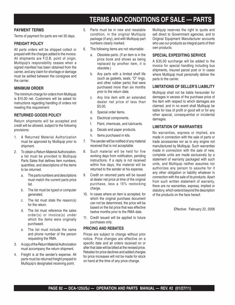
PAGE 82 — DCA-125USJ — OPERATION AND PARTS MANUAL — REV. #2 (01/27/11)
TERMS AND CONDITIONS OF SALE — PARTSPAYMENT TERMSTerms of payment for parts are net 30 days.
FREIGHT POLICYAll parts orders will be shipped collect or prepaid with the charges added to the invoice. All shipments are F.O.B. point of origin. Multiquip’s responsibility ceases when a signed manifest has been obtained from the carrier, and any claim for shortage or damage must be settled between the consignee and the carrier.
MINIMUM ORDERThe minimum charge for orders from Multiquip is $15.00 net. Customers will be asked for instructions regarding handling of orders not meeting this requirement.
RETURNED GOODS POLICYReturn shipments will be accepted and credit will be allowed, subject to the following provisions:
A Returned Material Authorization 1. must be approved by Multiquip prior to shipment.
To obtain a Return Material Authorization, 2. a list must be provided to Multiquip Parts Sales that defines item numbers, quantities, and descriptions of the items to be returned.
The parts numbers and descriptions a. must match the current parts price list.
The list must be typed or computer b. generated.
The list must state the reason(s) c. for the return.
The list must reference the sales d. order (s) or invoice (s) under which the items were originally purchased.
The list must include the name e. and phone number of the person requesting the RMA.
A copy of the Return Material Authorization 3. must accompany the return shipment.
Freight is at the sender’s expense. All 4. parts must be returned freight prepaid to Multiquip’s designated receiving point.
Parts must be in new and resalable 5. condition, in the original Multiquip package (if any), and with Multiquip part numbers clearly marked.
The following items are not returnable:6.
Obsolete parts. (If an item is in the a. price book and shows as being replaced by another item, it is obsolete.)
Any parts with a limited shelf life b. (such as gaskets, seals, “O” rings, and other rubber parts) that were purchased more than six months prior to the return date.
Any line item with an extended c. dealer net price of less than $5.00.
Special order items.d.
Electrical components.e.
Paint, chemicals, and lubricants.f.
Decals and paper products.g.
Items purchased in kits.h.
The sender will be notified of any material 7. received that is not acceptable.
Such material will be held for five 8. working days from notification, pending instructions. If a reply is not received within five days, the material will be returned to the sender at his expense.
Credit on returned parts will be issued 9. at dealer net price at time of the original purchase, less a 15% restocking charge.
In cases where an item is accepted, for 10. which the original purchase document can not be determined, the price will be based on the list price that was effective twelve months prior to the RMA date.
Credit issued will be applied to future 11. purchases only.
PRICING AND REBATESPrices are subject to change without prior notice. Price changes are effective on a specific date and all orders received on or after that date will be billed at the revised price. Rebates for price declines and added charges for price increases will not be made for stock on hand at the time of any price change.
Multiquip reserves the right to quote and sell direct to Government agencies, and toOriginal Equipment Manufacturer accounts who use our products as integral parts of their own products.
SPECIAL EXPEDITING SERVICEA $35.00 surcharge will be added to the invoice for special handling including busshipments, insured parcel post or in cases where Multiquip must personally deliver the parts to the carrier.
LIMITATIONS OF SELLER’S LIABILITYMultiquip shall not be liable hereunder fordamages in excess of the purchase price of the item with respect to which damages are claimed, and in no event shall Multiquip be liable for loss of profit or good will or for any other special, consequential or incidental damages.
LIMITATION OF WARRANTIESNo warranties, express or implied, are made in connection with the sale of parts or trade accessories nor as to any engine not manufactured by Multiquip. Such warranties made in connection with the sale of new, complete units are made exclusively by a statement of warranty packaged with such units, and Multiquip neither assumes nor authorizes any person to assume for it any other obligation or liability whatever in connection with the sale of its products. Apart from such written statement of warranty, there are no warranties, express, implied or statutory, which extend beyond the description of the products on the face hereof.
Effective: February 22, 2006

DCA-125USJ — OPERATION AND PARTS MANUAL — REV. #2 (01/27/11) — PAGE 83
1
NOTE PAGE
PARTS AND OPERATION MANUALOPERATION AND PARTS MANUAL
Your Local Dealer is:
HERE’S HOW TO GET HELPPLEASE HAVE THE MODEL AND SERIAL
NUMBER ON-HAND WHEN CALLING
UNITED STATESMultiquip Corporate Office MQ Parts Department
18910 Wilmington Ave.Carson, CA 90746 Contact: [email protected]
Tel. (800) 421-1244Fax (800) 537-3927
800-427-1244310-537-3700
Fax: 800-672-7877Fax: 310-637-3284
Service Department Warranty Department
800-421-1244310-537-3700
Fax: 310-537-4259 800-421-1244310-537-3700
Fax: 310-943-2249
Technical Assistance
800-478-1244 Fax: 310-943-2238
MEXICO UNITED KINGDOM
MQ Cipsa Multiquip (UK) Limited Head Office
Carr. Fed. Mexico-Puebla KM 126.5Momoxpan, Cholula, Puebla 72760 MexicoContact: [email protected]
Tel: (52) 222-225-9900Fax: (52) 222-285-0420
Unit 2, Northpoint Industrial Estate, Globe Lane,Dukinfield, Cheshire SK16 4UJContact: [email protected]
Tel: 0161 339 2223 Fax: 0161 339 3226
CANADA
Multiquip
4110 Industriel Boul.Laval, Quebec, Canada H7L 6V3Contact: [email protected]
Tel: (450) 625-2244 Tel: (877) 963-4411Fax: (450) 625-8664
© COPYRIGHT 2011, MULTIQUIP INC.
Multiquip Inc, the MQ logo and the MQ Power logo are registered trademarks of Multiquip Inc. and may not be used, reproduced, or altered without written permission. All othertrademarks are the property of their respective owners and used with permission.
This manual MUST accompany the equipment at all times. This manual is considered a permanent part of the equipment and should remain with the unit if resold.
The information and specifications included in this publication were in effect at the time of approval for printing. Illustrations, descriptions, references and technical data contained inthis manual are for guidance only and may not be considered as binding. Multiquip Inc. reserves the right to discontinue or change specifications, design or the information published in this publication at any time without notice and without incurring any obligations.