Embed Size (px)
Citation preview

WWW.WAHLBERG.DK · TELEPHONE +45 86 18 14 20 · CELL PHONE +45 40 52 20 88 · EMAIL: [email protected]
Jægergårdsgade 152/05A DK-8000 Aarhus C DENMARK WWW.WAHLBERG.DK
Forside
DC-Motor Controller
User Manual
Firmware V4.00

WWW.WAHLBERG.DK · TELEPHONE +45 86 18 14 20 · CELL PHONE +45 40 52 20 88 · EMAIL: [email protected]
2
Technical specifications:
Item No. : 250
Dimensions : 258 x 145 x 63 mm. (L-W-H)
Power supply : 230V AC
Power consumption : 120W
Power plug : powerCON TRUE1 Male & Female
Control signal : DMX 512
DMX channels : 5 channels
DMX plug : XLR 5pole Male & Female
Ambient temperature range : 0-40Cº
Net Weight : 1.8 kg.
Motor : DC motor 6-24 V Max 120W

WWW.WAHLBERG.DK · TELEPHONE +45 86 18 14 20 · CELL PHONE +45 40 52 20 88 · EMAIL: [email protected]
3
Product content
1 Controller box - for controlling a DC-motor.
1 PowerCON TRUE1 female plug
Functional description
Controlling a DC-motor by DMX signals from a light desk.
The DC-motor is able to run freely without positioning, with regulation of the speed and the direction.
The DC-motor is able to run with positioning, so the motor stops at a certain position.
Positioning run requires a feedback, either from a potentiometer or an impulse.
Overview
DMX Channels
MODE 0 – Free Run
DMX channel 1 – Stop/Direction
DMX channel 2 – Not in use
DMX channel 3 – Speed
MODE 1-6 – Potentiometer
DMX channel 1 – Position
DMX channel 2 – Not in use
DMX channel 3 – Speed
MODE 7-9 – Positioning with impulses (tacho)
DMX channel 1 – Position coarse
DMX channel 2 – Position fine
DMX channel 3 – Speed
DMX channel 4 – Reset Backward
DMX channel 5 – Reset Forward
MODE Functions
MODE 0: Free Run.
MODE 1: Positioning with potentiometer 1 with slow positioning.
MODE 2: Positioning with potentiometer 1 with normal positioning.
MODE 3: Positioning with potentiometer 1 with fast positioning.
MODE 4: Positioning with potentiometer 2 with slow Positioning.
MODE 5: Positioning with potentiometer 2 with normal Positioning.
MODE 6: Positioning with potentiometer 2 with fast Positioning.
MODE 7: Positioning with tacho with slow Positioning.
MODE 8: Positioning with tacho with normal Positioning.
MODE 9: Positioning with tacho with fast Positioning.

WWW.WAHLBERG.DK · TELEPHONE +45 86 18 14 20 · CELL PHONE +45 40 52 20 88 · EMAIL: [email protected]
4
Table 1 – Suggestions to mode settings according to Wahlberg products
Wahlberg Product
Id Product type
Mode
0 1 2 3 4 5 6 7 8 9
FR P1 P1 P1 P2 P2 P2 Imp Imp Imp
261 Actuator, 100mm, 20kg X
262 Actuator ,100mm, 30kg X
263 Actuator, 100mm, 50kg. X
264 Actuator, 100mm, 100kg. X
265 Actuator, 200mm, 100kg. X
266 Actuator, 400mm, 100kg. X
267 Actuator, 100mm, 300kg. X
268 Actuator, 200mm, 300kg. X
269 Actuator, 400mm, 300kg. X
272 Door opener X
273 Curtain track motor X
275 DC Motor, 60Rpm, 10 turn X
276 DC Motor, 110Rpm, 10 turn X
FR = Free Run, P1 = Potentiometer 1 – XLR - Motor plug. P2 = Potentiometer 2, - XLR - Motor Feedback plug. Imp = Tacho Impulses – XLR – Motor Feedback plug.
Settings
DMX address
The wanted DMX address is set on the Controller box,
The DMX address states from witch channel on the light desk, the DC- motor is controlled.
The DMX address can be set from 1 to 509. The controller box uses 3 DMX channels overall.
MODE
The wanted MODE function is set on the controller box.
Each MODE setting states a certain function. (See MODE functions).
The MODE can be set from 1 to 9.
WWW.WAHLBERG.DK · TELEPHONE +45 86 18 14 20 · CELL PHONE +45 40 52 20 88 · EMAIL: [email protected]
5
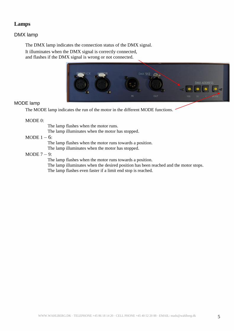
Lamps
DMX lamp
The DMX lamp indicates the connection status of the DMX signal.
It illuminates when the DMX signal is correctly connected,
and flashes if the DMX signal is wrong or not connected.
MODE lamp
The MODE lamp indicates the run of the motor in the different MODE functions.
MODE 0: The lamp flashes when the motor runs.
The lamp illuminates when the motor has stopped.
MODE 1 – 6:
The lamp flashes when the motor runs towards a position.
The lamp illuminates when the motor has stopped.
MODE 7 – 9:
The lamp flashes when the motor runs towards a position.
The lamp illuminates when the desired position has been reached and the motor stops. The lamp flashes even faster if a limit end stop is reached.

WWW.WAHLBERG.DK · TELEPHONE +45 86 18 14 20 · CELL PHONE +45 40 52 20 88 · EMAIL: [email protected]
6
DMX in
DC-motor controller
MODE lamp
DMX lamp
DMX start address
MODE
Motor
DMX out
Motor
feedback
Power
out
Power
in
Fuse
Connections.
Power supply
The controller-box is connected to the mains using the female poweCON TRUE1 plug.
DMX
The DMX is connected with a 5 pole XLR male plug.
Connections inside the DMX plug: see Electric connections.
DC-motor
The DC-motor is connected to the controller-box using a 5 pole XLR male plug.
Connections for the motor: see Electric connections. For details of suitable motors: see DC-motor
instruction.
Potentiometer / impulse
A potentiometer or an impulse is connected using a 5 pole XLR male plug.
Potentiometer or impulse is connected according to the desired form of positioning.
The potentiometer gives an easy, cheap and rough exact positioning, while an impulse gives a more precise
but relative positioning.
At impulse positioning, the position has to be reset every time the power is connected.
Connections for potentiometer / impulse: see Electric connection.
Fig. 1 – Connection overview

WWW.WAHLBERG.DK · TELEPHONE +45 86 18 14 20 · CELL PHONE +45 40 52 20 88 · EMAIL: [email protected]
7
DMX out
5-pole XLR male
1: GND
2: Data +
3: Data –
4: n.c.
5: n.c.
DC-motor controller
Motor
5-pole XLR male
1: Motor
2: Motor
3: Potentiometer1 + 5 Volt
4: Potentiometer1
Reference
5: Potentiometer1 GND
XL
XL
R
Motor feedback
5-pole XLR male
1: Impuls1.
2: impuls2.
3: Potentiometer2 + 5 Volt
4: Potentiometer2
Reference
5: Potentiometer2 GND
DMX in
5-pole XLR female
1: GND
2: Data +
3: Data –
4: n.c.
5: n.c.
XLR
male
XLR
female
XLR
female
XLR
female
Power in
220VAC
Power out
220VAC
PowerconTrue
Male and female
Electric connections
Fig. 2 –Connections
WWW.WAHLBERG.DK · TELEPHONE +45 86 18 14 20 · CELL PHONE +45 40 52 20 88 · EMAIL: [email protected]
8
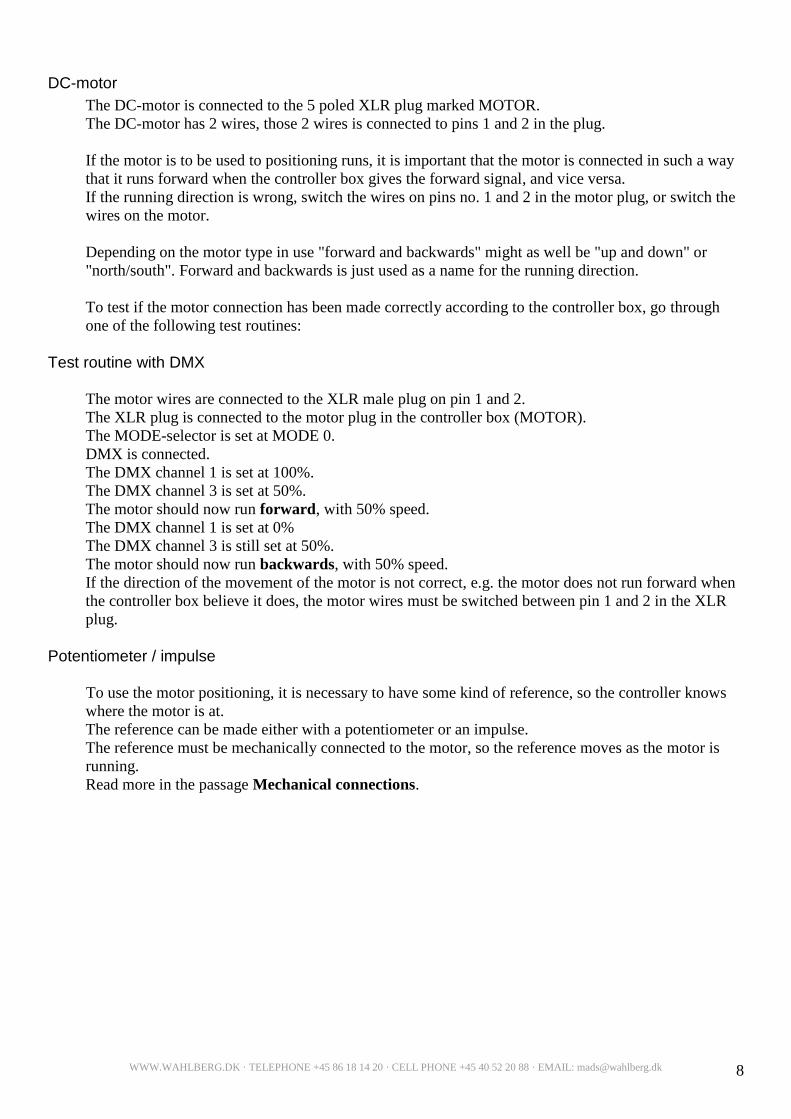
DC-motor
The DC-motor is connected to the 5 poled XLR plug marked MOTOR.
The DC-motor has 2 wires, those 2 wires is connected to pins 1 and 2 in the plug.
If the motor is to be used to positioning runs, it is important that the motor is connected in such a way
that it runs forward when the controller box gives the forward signal, and vice versa.
If the running direction is wrong, switch the wires on pins no. 1 and 2 in the motor plug, or switch the
wires on the motor.
Depending on the motor type in use "forward and backwards" might as well be "up and down" or
"north/south". Forward and backwards is just used as a name for the running direction.
To test if the motor connection has been made correctly according to the controller box, go through
one of the following test routines:
Test routine with DMX
The motor wires are connected to the XLR male plug on pin 1 and 2.
The XLR plug is connected to the motor plug in the controller box (MOTOR).
The MODE-selector is set at MODE 0.
DMX is connected.
The DMX channel 1 is set at 100%.
The DMX channel 3 is set at 50%.
The motor should now run forward, with 50% speed.
The DMX channel 1 is set at 0%
The DMX channel 3 is still set at 50%.
The motor should now run backwards, with 50% speed.
If the direction of the movement of the motor is not correct, e.g. the motor does not run forward when
the controller box believe it does, the motor wires must be switched between pin 1 and 2 in the XLR
plug.
Potentiometer / impulse
To use the motor positioning, it is necessary to have some kind of reference, so the controller knows
where the motor is at.
The reference can be made either with a potentiometer or an impulse.
The reference must be mechanically connected to the motor, so the reference moves as the motor is
running.
Read more in the passage Mechanical connections.

WWW.WAHLBERG.DK · TELEPHONE +45 86 18 14 20 · CELL PHONE +45 40 52 20 88 · EMAIL: [email protected]
9
pin 4
0 - 5v
Potentiometer
Ω
Backwards Forward
pin 3
+ 5v
pin 5
GND
1 2 3
Potentiometer as a reference.
The controller box has 2 inputs for positioning from a potentiometer:
Input 1 is in the motor plug (pin4).
Input 2 is in the motor feedback plug (pin 4).
Both inputs do the same, but allow you to connect the potentiometer in different ways.
See details under the Potentiometer connections section.
It is possible to use a number of different potentiometers,
the potentiometer just need to comply with the motor you
want to use, so you can get the best possible utilisation
of the motor positioning.
The value should be within 1-10Kohm
Examples of potentiometers:
3 turn - 5 turn -10 turn
360° turn - Liner potentiometer
Potentiometer connections
The potentiometer connections are important in relation
to the run of the motor.
When the DC-motor is correctly connected and its directions of movement are defined, the
potentiometer should be connected. The potentiometer is connected to the pins 3, 4 and 5 either in the
motor plug or in the motor feedback plug, depending of mode. See fig. 4 and 5
There are two ways of testing whether the potentiometer is correctly connected, in relation to the
direction of the movement. It is important to note that the potentiometer should not be in an outer
position when testing this. The potentiometer should instead be set in a middle position, to avoid
destroying it, if the connections are wrong.
Mount the potentiometer in such a way that the arm / shaft moves forward and backwards when the
motor runs forward and backwards.
Test:
1) Before connecting the potentiometer to the controller box MOTOR plug or MOTOR FEEDBACK
plug:
Measure the resistance in ohm between the potentiometer centre pin (2) and outer pin (3).
When the motor is running forward the ohm-value should decrease.
At the same time the ohm-value should increase between the centre pin and the other outer pin (1).
The outer pin (3) of the potentiometer is connected to pin 3 in the plug, the centre pin (1) to pin 4
and the last pin to pin 5. If the direction of the movement is the other way around pin 3 and 5
should be switched.
2) After the potentiometer is connected to the controller box:
Measure the voltage between pin 4 and 5 (+ on pin 4 and – on pin 5). The voltage should go
towards 5 volts when the motor is running forward and decrease when the motor is running
backwards.
Fig. 3 – Potentiometer connections

WWW.WAHLBERG.DK · TELEPHONE +45 86 18 14 20 · CELL PHONE +45 40 52 20 88 · EMAIL: [email protected]
10
Fig. 4 – Potentiometer connections in the MOTOR plug
Connection of a potentiometer to the MOTOR plug.
Used at positioning in mode 1 – 2 – 3.
Fig. 5 – Potentiometer connections in the MOTOR plug
Connection of a linear potentiometer to the MOTOR plug.
Used at positioning in mode 4 –5– 6.
1 2 3 4 5
MOTOR
5pole
XLR plug
1 2 3 4 5
MOTOR
Feedback
XLR plug
Motor
+ -
Linear potentiometer for feedback
Forward Backwards
DC Motor Controller
1 2 3 4 5
MOTOR 5pole
XLR plug
Motor
+ -
Linear potentiometer for feedback
1 2 3 4 5
MOTOR Feedback
XLR plug
Forward Backwards
DC Motor Controller

WWW.WAHLBERG.DK · TELEPHONE +45 86 18 14 20 · CELL PHONE +45 40 52 20 88 · EMAIL: [email protected]
11
End stop Forward
The pulse as reference. The impulse is connected to impulse 1 and impulse 2 on the Motor Feedback XLR plug.
With pulse feedback the position must be reset at start.
The position is reset by running the motor backwards (DMX channel 4) until the wanted back position is
reached. At this point channel 4 is set on 0 and the back position is reset. You can benefit from using the
rear end limit stop to reset up against. The movement area is set at channel 5. This is done by running channel 5 over zero, thereby the motor is
running forward. When the wanted maximum position is reached, channel 5 is set on 0, the motor stops
and the aria is set. Here the other end limit stop can be used with benefit.
The movement area is stored in the controlling box, and it is only necessary to adjust it once.
End stop.
When impulse is used for positioning, it is possible to use the two potentiometer inputs as end stops.
End stop back is connected to potentiometer 1 input (Motor XLR pin 4) and End stop forward is
connected to potentiometer 2 input (Motor Feedback XLR pin 4).
If an end stop is reached while running, the position will be reset to a position a small distance from
the end stop to prevent the end stops from being activated during normal running.
Both end stops should have a 1 Kohm resistance between pin 4 (5V) and pin 3 (the end stop input).
Pin 4 and pin 5 (GND) has to be connected to make the motor run. The Normally closed switch (NC)
inside the end stop is therefore connected to pin 4 and pin 5.
Fig. 6 – End stop connections
Moving
object
Pull up resistance
1 kohm
Impulse
Supply +
Impulse – Chanel A
Impulse – Chanel B
Supply GND
DC motor Controller
Mode 7 – 9
Positioning with Impulse
End stop Backwards
1 2 3 4 5
MOTOR 5pole
XLR plug
1 2 3 4 5
MOTOR Feedback
XLR plug
Motor
+ -
End stop connections for the controller.
End stops are used in mode 7 – 9 where they are
positioned by an impulse.

WWW.WAHLBERG.DK · TELEPHONE +45 86 18 14 20 · CELL PHONE +45 40 52 20 88 · EMAIL: [email protected]
12
Mechanical connections
DC-motor guide
It is possible to use many different DC-motors with the controller box.
The power supply for the controller box is 24 volt. This means the voltage on the motor at maximum
speed is 24VDC. When a DC-motor is connected it is therefore important that this motor is for 24 V
DC or more.
If the rated voltage on the motor is less than 24 volt, it is important never to run at maximum speed.
Please be aware of the motor, if it should become very hot or smell burned, it may be due to the motor
and power supply having an incorrect voltage in relation to each other.
DC-motor with potentiometer
When you want to use positioning of the motor, it is important to use an appropriate potentiometer.
This must be understood in the sense that the motor and the potentiometer, must fit mechanically, so
when the motor is running the potentiometer follows along. The outer position of the motor must also
be the outer limit of the potentiometer. In this way the potentiometer is used as a reference source to
tell the controller box where the motor is located, so it can make a properly positioning of the motor.
DC-motor with pulse
The motor and the impulse have to be able to follow each other mechanically when the motor runs.
The impulses should follow the DC-motor forward and backwards.
In this way the controller uses the impulses for counting where the motor is and thereby it is able to
position the motor correct.

WWW.WAHLBERG.DK · TELEPHONE +45 86 18 14 20 · CELL PHONE +45 40 52 20 88 · EMAIL: [email protected]
13
MODE functions
To use the controller box the MODE must be set. Each MODE setting has a given function, with a
basic use of the DMX channels.
MODE 0
Free Run
The motor runs freely, without positioning, with regulation of speed and direction.
DMX channel 1: Direction setting.
0 – 33% Back
34 – 66% Stop
67 – 100% Forward
DMX channel 2: Speed setting.
0% Stop
1 – 100% Max. speed
Example:
DMX channel 2 is set at 50% (speed).
DMX channel 1 is set between 67-100%
The Motor run forward with the middle speed set at 50%
MODE 1 – 6
Positioning with potentiometer
The motor is positioned by a potentiometer in the motor plug, with regulation of the speed.
DMX channel 1: Position of the motor.
0% Full backwards
50% Middle position
100% Full forward
DMX channel 2: Speed setting.
1-100% Given speed
0% Stop
Example:
DMX channel 1 is set at 65%
DMX channel 2 is set at 40%
The motor runs to the set position about 2/3 of full forward (65%), with a speed just below the
middle (40%).

WWW.WAHLBERG.DK · TELEPHONE +45 86 18 14 20 · CELL PHONE +45 40 52 20 88 · EMAIL: [email protected]
14
MODE 7 – 9
Positioning with impulse
The motor is positioned by a tacho sensor in the motor feedback plug, with speed regulation.
DMX channel 1+2: Position of the motor.
0% Full backwards
50% Middle position
100% Full forward
DMX channel 3: Speed setting.
1-100% Given speed
0% Stop
DMX channel 4: Reset against back
1-100% Reset backwards with speed 1-100
0% Stop
DMX channel 5: Reset against forward
1-100% Reset forward with speed 1-100
0% Stop
Example:
DMX channel 1 is set at 65%
DMX channel 2 is set at 40%
The motor runs to the set position about 2/3 of full forward (65%), with a speed just below the
middle (40%).
Getting started
If you are using the DC motor for the first time it is a good idea to read this, to learn how to get started
properly and what to pay extra attention to..
Setting
Before connecting the controller box it is a good idea to set both the MODE function and the DMX start
address. See more about settings in the Settings section.
In this section we describe running in MODE 2.
Connection
When the mechanical feedback is mounted on the potentiometer and it is electrical connected, both power
and DMX can be connected as described in the Connection section.
Remember to test the positioning before the potentiometer is run beyond its mechanical limits
Positioning running
The desired position is set on the DMX channel 1 and 2, witch are the coarse and fine settings for
positioning. 100% is the most forward position and 0% is the back position. Speed is set on the DMX
channel 3, where 100% is max. speed and 1% is min. speed. DMX channel 3 must always be above
zero (0) before the motor runs. This way it also acts as a main switch.

WWW.WAHLBERG.DK · TELEPHONE +45 86 18 14 20 · CELL PHONE +45 40 52 20 88 · EMAIL: [email protected]
15
Errors
DMX error
At error in the DMX signal:
Check for wrong or loose connections in the DMX plug
Check that there is a circuit in the cable.
Error in the motor run If error in the motor run:
Check that the connections of the motor plug are correctly made (pin 1 and 2)
Check that there is a circuit in the cable.
Use the test function of MODE 7 and 8, to check if the motor is able to run backwards and forward
without DMX signal. See MODE functions.
Check that the motor is not dead. For example by disconnecting the motor plug from the controller
box and instead connect the voltage directly to the pins of the motor. If the motor does not run, it must
be changed.
Remember, If you apply voltage directly to the motor, it should not exceed the rated voltage on the
motor.
Error in positioning
If error in the positioning of the motor:
Check that the motor and potentiometer are properly connected.
Check that there is a circuit in the cable.
Check that the potentiometer is not broken and has not been twisted further than its outer limit.
Check that the potentiometer mechanically follows the run of the motor.


![[Short Stories] - Rise of the New Sith 3 - The Sith System (Brendon Wahlberg)](https://img.dokumen.tips/doc/110x75/577d2fa71a28ab4e1eb24198/short-stories-rise-of-the-new-sith-3-the-sith-system-brendon-wahlberg.jpg)


![[Short Stories] - Rise of the New Sith 2 - Rising Stars (Brendon Wahlberg)](https://img.dokumen.tips/doc/110x75/577d2fa71a28ab4e1eb24199/short-stories-rise-of-the-new-sith-2-rising-stars-brendon-wahlberg.jpg)


