Embed Size (px)
Citation preview

UNIT - 4 TESTING OF DC MACHINES
Testing of DC machines can be broadly classified as
i) Direct method of Testing
ii) Indirect method of testing
DIRECT METHOD OF TESTING:
In this method, the DC machine is loaded directly by means of a brake applied to a water cooled
pulley coupled to the shaft of the machine. The input and output are measured and efficiency is
determined by η=
. It is not practically possible to arrange loads for machines of large
capacity.
INDIRECT METHOD OF TESTING:
In this method, the losses are determined without actual loading the machine. If the losses are
known, then efficiency can be determined. Swinburne’s test and Hopkinson’s test are commonly
used on shunt motors. But, as series motor cannot be started on No-load,these tests cannot be
conducted on DC series motor.
(i) BRAKE TEST: is a direct method of testing.
In this method of testing motor shaft is coupled to a
Water cooled pulley which is loaded by means of weight
as shown in figure4.1.
= suspended weight in kg
= Reading in spring balance in kg
R = radius of pulley
N = speed in rps
V = Supply voltage
I = Full Load Current
Net pull due to friction = ( −) kg
= 9.81 ( −) Newton ………………. 1
Shaft torque = −) − .
R
S
Figure 4.1
www.alls
yllab
us.co
m
www.allsyllabus.com
vtu.allsyllabus.com
= 9.81 ( −) − ……………… 2
Motor output power = 2 Watt
= −)2 watts ………………. 3
Or 9.81 ( −)2 watt.
= 61.68 N ( −) ……….. 4
Input power = VI watts ………………. 5
Therefore efficiency =
=
. !" # $
%& ………… 6
This method of testing can be used for small motors only because for a large motor it is difficult to
arrange for dissipation of heat generated at the brake.
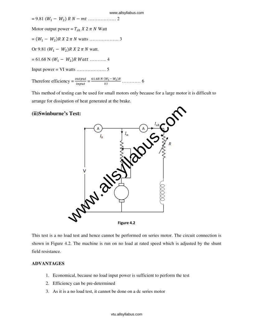
(ii)Swinburne’s Test:
This test is a no load test and hence cannot be performed on series motor. The circuit connection is
shown in Figure 4.2. The machine is run on no load at rated speed which is adjusted by the shunt
field resistance.
ADVANTAGES
1. Economical, because no load input power is sufficient to perform the test
2. Efficiency can be pre-determined
3. As it is a no load test, it cannot be done on a dc series motor
Figure 4.2 www.alls
yllab
us.co
m
www.allsyllabus.com
vtu.allsyllabus.com
DISADVANTAGES
1. Change in iron loss from no load to full load is not taken into account. (Because of armature
reaction, flux is distorted which increases iron losses).
2. Stray load loss cannot be determined by this test and hence efficiency is over estimated.
3. Temperature rise of the machine cannot be determined.
4. The test does not indicate whether commutation would be satisfactory when the machine is
loaded.
IO = No load current; Ish = shunt field current
Iao = No load armature current = (Io - Ish)
V= Supply Voltage
No load input =VIo watts.
No load power input supplies
(i) Iron losses in the core
(ii) Friction and windings loss and
(iii) Armature copper loss.
Let I = load current at which efficiency is required
Ia = I – Ish if machine is motoring; I + Ish if machine is generating
Efficiency as a motor:
Input = VI; Ia2ra = (I- Ish)
2ra
Constant losses Wc = VIo – (Io – Ish)2ra …………… 7
Total losses = (I- Ish)2ra + Wc
Therefore efficiency of motor = "'(
; = )*–*"*,- ./012
%& ……. 8
EFFICIENCY OF A GENERATOR:
Output = VI
Ia2ra = (I+Ish)
2ra
Total losses = Wc+(I+Ish)2ra …………………………………….. 9
Efficiency of generator =
0'(=
%&
%&0&0&34 #560 7
……… 10
www.alls
yllab
us.co
m
www.allsyllabus.com
vtu.allsyllabus.com

1. A 220 V DC shunt motor at No-load takes a current of 2.5 A. the resistance of the armature
and shunt field are 0.8Ω and 200Ω respectively. Estimate the efficiency of the motor when the
input current is 32 A.
SOLUTION: No-load input = 220 x 2.5 = 500 W
8 =9
99 = 1.1 A;8: = 2.5 − 1.1 = 1.4>;8:
?: = 1.4) X 0.8 = 1.6 W
Constant losses = 550 – 1.6 = 548.4 W
When input current is 32 A, Ia = 32 – 1.1 = 30.9 A
8:?: = 30.9)0.8 = 764; Total losses = 764 + 548.4 = 1315 W
Input = 220 X 32
Therefore output = (220 X 32) – 1315 W
Therefore η = "'(
= 81.3 %
2. A 440V D.C Shunt motor takes no load current of 25A. The resistance of shunt field and
armature are550 Ω & 1.2Ω respectively. The full load line current is 32A. Determine the full
load output &efficiency of the motor.
SOLUTION:SOLUTION:SOLUTION:SOLUTION:inputonnoload=VI=440×2.5=1100W8= %$34=
ZZ9[[9=0.8A;8 = 8 + 8:,therefore,8: = 8 − 8 =2.5-0.8=1.7A
efgfh?i?jkigfll = 8:?:=(1.7)2×1.2=3.468Wkfelegfll = menifeefgfh − efgfh?i?jkigfll=1100-3.468=1096.532W8o=32A,8:=32-0.8=31.2A;Armaturecopperloss=(31.2)1.2 = 1168.128Totallosses=1168.128+1096.532=2264.66Wη = tuvwx"yz,,,tuvwx =(ZZ9×|)"Z.(ZZ9×|) ×100=83.9%
2. A 500 V DC shunt motor when running on No-load takes 5 A. Armature resistance is 0.5Ω and
shunt field resistance is 250Ω. Find the output in kW and η of the motor when running on full
load and taking a current of 50 A.
www.alls
yllab
us.co
m
www.allsyllabus.com
vtu.allsyllabus.com
(iii) Hopkinson’s Or Regenerative Or Back To Back Test:
This is a regenerative test in which two identical DC shunt machines are coupled mechanically and
tested simultaneously. One of the machines is run as a generator while the other as motor supplied by
the generator. The set therefore draws only losses in the machines. The circuit connection is shown
in Figure 4.3. The machine is started as motor and its shunt field resistance is varied to run the motor
at its rated speed. The voltage of the generator is made equal to supply voltage by varying the shunt
field resistance of the generator which is indicated by the zero reading of the voltmeter connected
across the switch. By adjusting the field currents of the machines, the machines can be made to
operate at any desired load with in the rated capacity of the machines
ADVANTAGES:
i. The two machines are tested under loaded conditions so that stray load losses are
accounted for.
ii. Power required for the test is small as compared to the full load powers of the two
machines. Therefore economical for long duration tests like “Heat run tests”.
iii. Temperature rise and commutation qualities can be observed.
iv. By merely adjusting the field currents of the two machines the two machines can be
loaded easily and the load test can be conducted over the complete load range in a short
time.
DISADVANTAGES:
i. Availability of two identical machines
ii. Both machines are not loaded equally and this is crucial in smaller machines.
iii. There is no way of separating iron losses of the two machines which are different because
of different excitations.
iv. Since field currents are varied widely to get full load, the set speed will be greater than
rated values.
The efficiency can be determined as follows:
www.alls
yllab
us.co
m
www.allsyllabus.com
vtu.allsyllabus.com
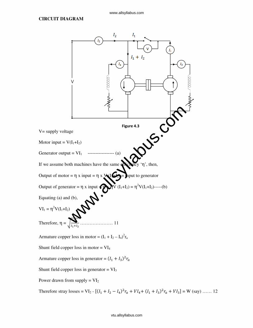
CIRCUIT DIAGRAM
V= supply voltage
Motor input = V(I1+I2)
Generator output = VI1 ----------------- (a)
If we assume both machines have the same efficiency ‘η’, then,
Output of motor = η x input = η x V (I1+I2) = input to generator
Output of generator = η x input = η x ηV (I1+I2) = η2V(I1+I2)-----(b)
Equating (a) and (b),
VI1 = η2V(I1+I2)
Therefore, η = ~ &!&!0&# ………………… 11
Armature copper loss in motor = (I1 + I2 – I4)2ra
Shunt field copper loss in motor = VI4
Armature copper loss in generator = (8 + 8|)?:
Shunt field copper loss in generator = VI3
Power drawn from supply = VI2
Therefore stray losses = VI2 - (8 + 8 − 8Z)?: + 8Z+(8 + 8|)?: + 8| = W (say) …… 12
Figure 4.3
www.alls
yllab
us.co
m
www.allsyllabus.com
vtu.allsyllabus.com

Stray losses/motor = ……………… 13
Therefore for generator
Total losses = (8 + 8|)?: + 8| + = Wg (say) ………………. 14
Output = VI1, therefore ηgenerator = %&!
%&!0 =
0'( ……….. 15
For motor,
Total losses =(8 + 8 − 8Z)?: + 8Z + = (l) Input to motor = V(8 + 8) Therefore ηmotor =
%(&!0&#)" %(&!0&#) …………16
www.alls
yllab
us.co
m
www.allsyllabus.com
vtu.allsyllabus.com

ALTERNATIVE CONNECTION:
The Figure 4.4 shows an alternate circuit connection for this test. In this connection the shunt field
windings are directly connected across the lines. Hence the input current is excluding the field
currents. The efficiency is determined as follows:
Motor armature copper loss =(8+8)?:
Generator armature copper loss = 8?:
Power drawn from supply = VI1
Stray losses = 8 − (8+8)?:−8?: = W(say) ………….. 17
Stray loss/motor = ……………. 18
MOTOR EFFICIENCY: motor input = armature input + shunt field input
= V(8+8) + 8| Motor loss = Armature copper loss + Shunt copper loss + stray losses = (8 + 8)?: + 8| + .. 19
Therefore ηmotor = 5"5'(
5 …………. 20
Generator efficiency ‘η’: Generator output = VI2
Generator losses = 8?: + 8Z + ……………… 21
ηgenerator = %&#
%�((5:5'( ……………………. 22
Figure 4.4
www.alls
yllab
us.co
m
www.allsyllabus.com
vtu.allsyllabus.com
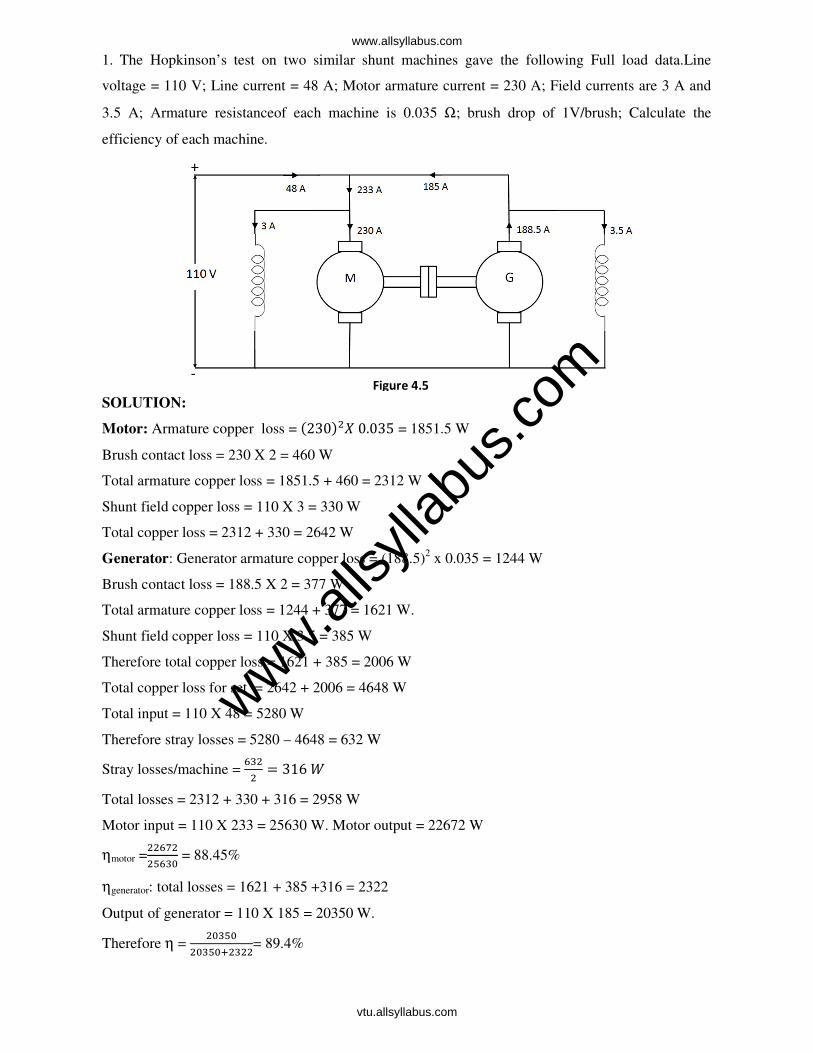
1. The Hopkinson’s test on two similar shunt machines gave the following Full load data.Line
voltage = 110 V; Line current = 48 A; Motor armature current = 230 A; Field currents are 3 A and
3.5 A; Armature resistanceof each machine is 0.035 Ω; brush drop of 1V/brush; Calculate the
efficiency of each machine.
SOLUTION:
Motor: Armature copper loss = (230 0.035 = 1851.5 W
Brush contact loss = 230 X 2 = 460 W
Total armature copper loss = 1851.5 + 460 = 2312 W
Shunt field copper loss = 110 X 3 = 330 W
Total copper loss = 2312 + 330 = 2642 W
Generator: Generator armature copper loss = (188.5)2 x 0.035 = 1244 W
Brush contact loss = 188.5 X 2 = 377 W
Total armature copper loss = 1244 + 377 = 1621 W.
Shunt field copper loss = 110 X 3.5 = 385 W
Therefore total copper loss = 1621 + 385 = 2006 W
Total copper loss for set = 2642 + 2006 = 4648 W
Total input = 110 X 48 = 5280 W
Therefore stray losses = 5280 – 4648 = 632 W
Stray losses/machine = |
316
Total losses = 2312 + 330 + 316 = 2958 W
Motor input = 110 X 233 = 25630 W. Motor output = 22672 W
ηmotor =
[|9 = 88.45%
ηgenerator: total losses = 1621 + 385 +316 = 2322
Output of generator = 110 X 185 = 20350 W.
Therefore η = 9|[9
9|[90|= 89.4%
Figure 4.5
www.alls
yllab
us.co
m
www.allsyllabus.com
vtu.allsyllabus.com

2. In a Hopkinson’s test on a pair of 500 V, 100 kW shunt generator. The following data was
obtained:Auxiliary supply 30 A at 500 V; Generator output current 200 A; Field current 3.5 A and
1.8 A; ra = 0.075 Ω for each machine; voltage drop at brushes = 2 V/machine; calculate the
efficiency of the machine as a generator.
SOLUTION:
Motor armature copper loss = (230)2 X 0.075 + 230 X 2 = 4428 W
Motor field copper loss = 500 X 1.8 = 900 W
Generator armature copper loss = (200)2 X 0.075 + 200 X 2 = 3400 W
Generator field copper loss = 500 X 3.5 = 1750 W.
Total copper loss for 2 machines = 4428 + 900 + 3400 + 1750 = 10478 W
Power drawn = 500 X 30 = 15000 W
Therefore stray loss for the two machines = 15000 – 10478 = 4522 W.
Stray loss / machine = Z[
= 2261 W
Therefore total losses in generator = 3400 + 1750 + 2261 = 7411 W
Generator output = 500 X 200 = 100000 W
Therefore ηgenerator = 99999
999990Z = 93.09 %
3. In a Hopkinson test on 250 V machine, the line current was 50 A and the motor current is 400 A
not including the field currents of 6 and 5 A. the armature resistance of each machine was 0.015Ω.
Calculate the efficiency of each machine.
Figure 4.6
www.alls
yllab
us.co
m
www.allsyllabus.com
vtu.allsyllabus.com
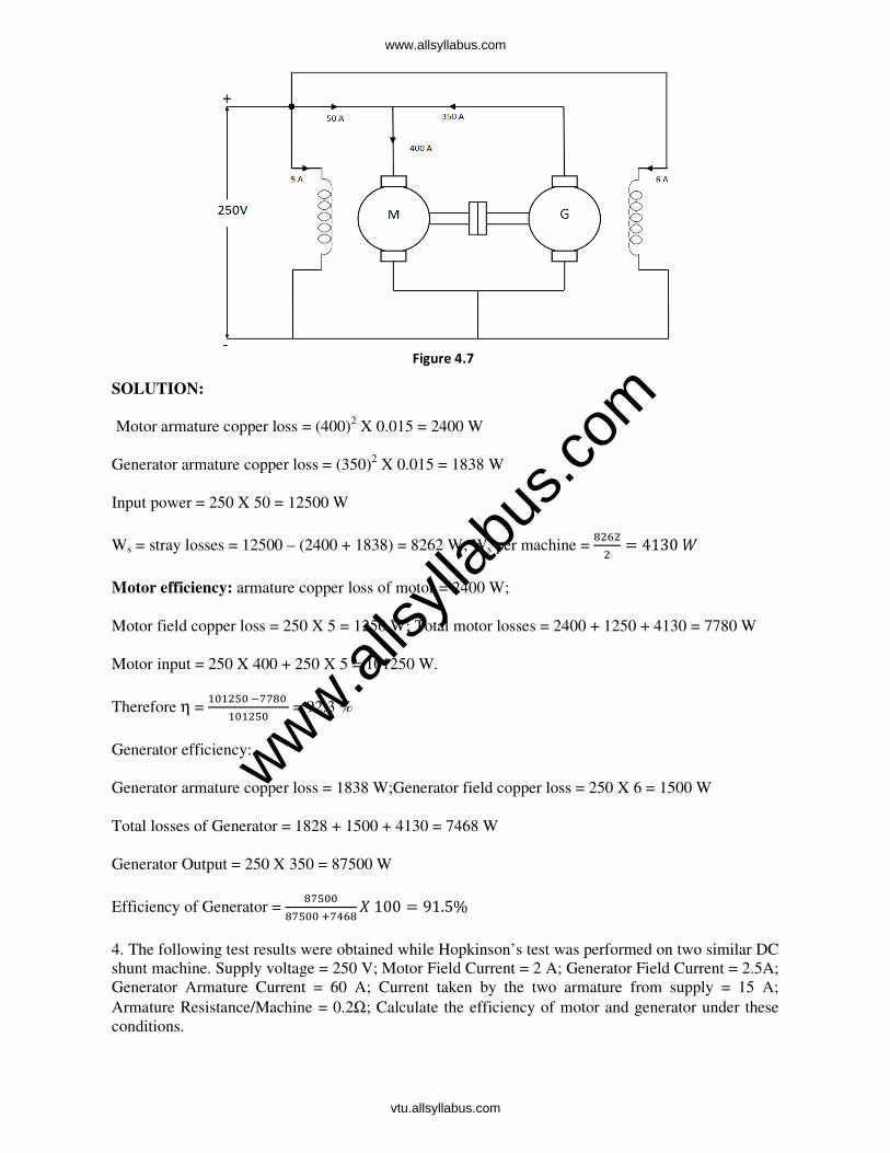
SOLUTION:
Motor armature copper loss = (400)2 X 0.015 = 2400 W
Generator armature copper loss = (350)2 X 0.015 = 1838 W
Input power = 250 X 50 = 12500 W
Ws = stray losses = 12500 – (2400 + 1838) = 8262 W; Ws per machine =
4130
Motor efficiency: armature copper loss of motor = 2400 W;
Motor field copper loss = 250 X 5 = 1250 W; Total motor losses = 2400 + 1250 + 4130 = 7780 W
Motor input = 250 X 400 + 250 X 5 = 101250 W.
Therefore η = 9[9"9
9[9 = 92.3 %
Generator efficiency:
Generator armature copper loss = 1838 W;Generator field copper loss = 250 X 6 = 1500 W
Total losses of Generator = 1828 + 1500 + 4130 = 7468 W
Generator Output = 250 X 350 = 87500 W
Efficiency of Generator = [99
[990Z100 91.5%
4. The following test results were obtained while Hopkinson’s test was performed on two similar DC
shunt machine. Supply voltage = 250 V; Motor Field Current = 2 A; Generator Field Current = 2.5A;
Generator Armature Current = 60 A; Current taken by the two armature from supply = 15 A;
Armature Resistance/Machine = 0.2Ω; Calculate the efficiency of motor and generator under these
conditions.
Figure 4.7
www.alls
yllab
us.co
m
www.allsyllabus.com
vtu.allsyllabus.com

(iv) Field test for series motor:
Figure 4.8 shows the circuit for fields test. This test is applicable to two similar series motor. One of
the machine runs as a motor and drives a generator whose output is wasted in a variable load ‘R’.
Both machine field coils are in series and both run at same speed so that iron and friction losses are
made equal.
Load resistance ‘R’ is varied till the motor current reaches its full load value.
V = Supply voltage
I1 = Motor current
V2 = Generator terminal voltage
I2 = Load current
Input = VI1 and output = V2I2
Ra and Rse = hot resistances.
Total losses in the set Wt = VI1 – V2I2 …………………………….... 23
Armature and Field copper losses Wc = (Ra + 2 rse) I12 + Ia
2Ra ……… 24
Stray losses forthe set = Wt – Wc ……………………………………..25
R
Figure 4.8
www.alls
yllab
us.co
m
www.allsyllabus.com
vtu.allsyllabus.com

Stray losses per machine Ws = " 7 ………………………………… 26
Motor efficiency: input = V1I1
Losses = (: + ()8 + = (l) ηmotor=
%&!0 %&! ………… 27
Generator efficiency: η of generator is of little use, because its field winding is separately excited
Generator output = VI2
Field copper loss =8?( Armature copper loss =8?:Totallosses=8?( +8?: +=Wg(say)……………………. 28ηgenerator= %&#%#0 ………………29
1. A test on two coupled similar tramway motors with their fields connected in series, gave the
following results when one machine acted as a motor and the other as a generator.Motorarmature
current = 56 A; Armature voltage = 550 V; Voltage drop across the field winding = 40V; Generator:
armature current = 44 A; Armature voltage = 400 V; Field drop across the field winding = 40V;
Resistance of each armature = 0.3Ω; Calculate the efficiency of motor and gearing at this load.
Figure 4.9
www.alls
yllab
us.co
m
www.allsyllabus.com
vtu.allsyllabus.com

SOLUTION:
Total input = 630 X 56 = 35280 W
Output = 400 X 44 = 17600 W
Total losses = 35280 – 17600 = 17680 W
Rse = Z9[ = 0.714 Ω
Total copper loss = (0.3 + 2 X 0.714) 562 + 44
2 X 0.3 = 6006 W
Therefore stray losses = 17600 – 6006 = 11674 W
Stray losses per motor = Z = 5837 W
Motor efficiency: motor input = 590 X 56 = 33040 W
Armature circuit copper loss = (0.714 + 0.3) 562 = 3180 W
Stray losses = 5837 W
Total losses = 3180 + 5837 = 9017 W
Therefore efficiency = ||9Z9"9||9Z 100 = 72.7%
Generator efficiency: Armature copper loss = 0.3 X 442 = 581 W
Series field copper loss = 40 X 56 = 2240 W.
Stray losses = 5837 W
Therefore total losses = 581 + 2240 + 5837 = 8658 W
Output = 400 X 44 = 17600 W
Therefore ηgenerator = 99
990[100 = 67%
3. A field’s test on two similar series machines gave the following data; Motor: Armature current:
60A; Voltage across armature: 500V; Voltage across field: 40V; Generator: Terminal voltage: 450V;
Output current 46A; Voltage across field:40V; Armature resistance of each machine is 0.25Ω.
Calculate the efficiency of both the machines. SOLUTIONSOLUTIONSOLUTIONSOLUTION::::
Total input = 580×60=34800W
Output =450×46=20700W
Therefore total losses in 2machines = 34800-20700=14100W
www.alls
yllab
us.co
m
www.allsyllabus.com
vtu.allsyllabus.com

Total cu loss = (0.25+ 2×0.67)(60)2+ (46)
2=6253W
Stray losses of the set = 14100-6253= 7847W
Stray loss per machine = Z =3923.5W
Efficiency of Motor;
Motor input= motor armature voltage × armature current =540 × 60 =32400W
Armature cu loss = (0.25 + 0.67) (60)2= 3312W
Total losses = 3312 + 3923.5 =7235.5W
ηofmotor = 32400"7235.532400
= 77.67 %
Efficiency of Generator; generator output= 450 × 46 =20700W
Armature cu loss = (0.25) (46)2= 529 W
Series field cu loss = 40× 60 =2400W
Total losses = 2400 + 529 + 3923.5 =6852.5W
ηofgenerator = 20700
2070006852.5X 100 = 75.1 %
Figure 4.10
www.alls
yllab
us.co
m
www.allsyllabus.com
vtu.allsyllabus.com
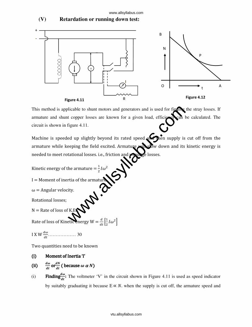
(V) Retardation or running down test:
This method is applicable to shunt motors and generators and is used for finding the stray losses. If
armature and shunt copper losses are known for a given load, efficiency can be calculated. The
circuit is shown in figure 4.11.
Machine is speeded up slightly beyond its rated speed and then supply is cut off from the armature while keeping the field excited. Armature will slow down and its kinetic energy is needed to meet rotational losses. i.e., friction and windage losses.
Kinetic energy of the armature = 8 I = Moment of inertia of the armature ω = Angular velocity. Rotational losses; N = Rate of loss of K.E. Rate of loss of Kinetic energy W =
8
I X W ……………… 30
Two quantities need to be known (i)(i)(i)(i) Moment of Inertia ‘I’Moment of Inertia ‘I’Moment of Inertia ‘I’Moment of Inertia ‘I’ (ii)(ii)(ii)(ii)
¡¢¡£ orororor¡¤
¡£ ( because ( because ( because ( because ¢ αααα ¤)))) (i) FindingFindingFindingFinding¡¢
¡£ : The voltmeter ‘V’ in the circuit shown in Figure 4.11 is used as speed indicator
by suitably graduating it because E ∝ . when the supply is cut off, the armature speed and
B
P
N
A O t
Figure 4.11 Figure 4.12
www.alls
yllab
us.co
m
www.allsyllabus.com
vtu.allsyllabus.com
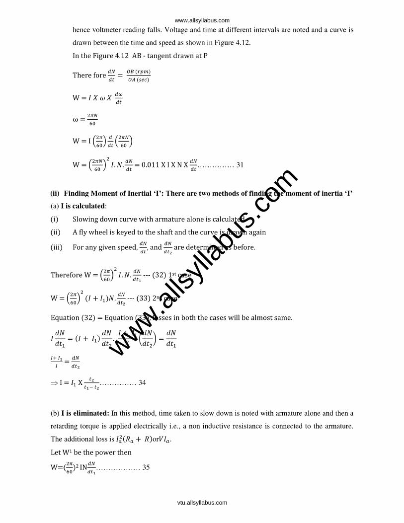
hence voltmeter reading falls. Voltage and time at different intervals are noted and a curve is
drawn between the time and speed as shown in Figure 4.12.
In the Figure 4.12 AB - tangent drawn at P There fore
= ©ª (5)©« ((¬)
W = 8
ω =
9 W = I ®
9¯ ®
9 ¯ W = ®
9 ¯ 8. . = 0.011 X I X N X
…………… 31
(ii) Finding Moment of Inertial ‘I’: There are two methods of finding the moment of inertia ‘I’
(a) I is calculated:
(i) Slowing down curve with armature alone is calculated. (ii) A fly wheel is keyed to the shaft and the curve is drawn again (iii) For any given speed,
, and #
are determined as before.
Therefore W = ®9¯ 8. .
! --- (32) 1st case
W = ®9¯ (8 + 8).
# --- (33) 2nd case
Equation (32) = Equation (33), losses in both the cases will be almost same.
8 hh
= (8 + 8) hh
. 8 + 88 °h
h± = h
h
&0 &!& =
#
⇒ I = 8 X #!" #
…………… 34
(b) I is eliminated: In this method, time taken to slow down is noted with armature alone and then a
retarding torque is applied electrically i.e., a non inductive resistance is connected to the armature.
The additional loss is 8:(: + )or8:.
Let W1 be the power then W=(
9)2 IN!
……………… 35
www.alls
yllab
us.co
m
www.allsyllabus.com
vtu.allsyllabus.com
W + W1 = ( 9)2IN
#………… 36; if dN is same.
!
=rate of change of speed without electrical load #
=rate of change of speed with electrical load
1 0 1 1 =
²³²#²³²!
…… 37 or 1 0 1 1 = !
#or W= W1 × #
!" # or W= W1 × #
!" #………. 38
1. A retardation test is made on a separately excited. DC machine as a motor the induced voltage falls from 240V to 225V in 25 secs on opening the armature circuit & 6 secs on suddenly changing the armature connection from supply to a load resistance taking 10A (average). Find the efficiency of the machine when running as a motor& taking a current of 25A on a supply of 250V. The resistance of its arm is 0.4Ω & that of its field winding is 250Ω. SOLUTION:SOLUTION:SOLUTION:SOLUTION: Average voltage across load = 240+225/2 = 232.5 Iav = 10A Power absorbed = w’ = 232.5 X 10 = 2325w t1 =30sec & t2= 6sec, W = stray loss. Therefore W = W’ X #
!" #; therefore W = 2325 X
[" = 734.1w. Input current = 25A; Ish = [9
[9= 1A therefore Ia = 25 - 1= 24A Armature Current loss = (24)2 X 0.4 = 230.4 w, Shunt current loss = 250 X 1 = 250w Therefore total losses = 734.1 + 230.4 +250 = 1215 w Input = 25 X 25 = 6250w output = 6250 -1215 = 5035w Therefore efficiency = [9|[
[9= 0.806 or 80.6% 2. In a retardation test on a separately motor, the induced emf in the armature falls from 220V to 190V in 30seconds on disconnecting the armature from the supply. The same fall takes place in 20seconds if, immediately after disconnection, armature is connected to a resistance which takes 10A (average) during this fall, find the stray losses of motor. SOLUTION:SOLUTION:SOLUTION:SOLUTION: W = stray losses Average voltage across resistance = 9909
= 195 Average current = 10A; Power absorbed W’ = 1950w ¹= #
!" #; W = 1950 9
|9"9 = 3900w.
www.alls
yllab
us.co
m
www.allsyllabus.com
vtu.allsyllabus.com

(2) A retardation test is carried out on a 1000rpm D.C machine. The time taken for the speed to fall from 1030 rpm to 970rpm is (a) 36secs with no excitation. (b) 15secs with full excitation & (c) 9 seconds with full excitation & the armature supplying an extra load of 10A at 219V. Calculate (1) The moment of inertia of the armature is kg.m2. (2) Iron loss and (3) Themechanical losses at the mean speed of 1000rpm. SOLUTION:SOLUTION:SOLUTION:SOLUTION:
(i) When the arm slows down with no excitation its kinetic energy is used to over come mechanical losses only (no flux, no Iron loss)
(ii) With excitation, Kinetic Energy is used to supply mechanical & iron losses ie., stray losses. (iii) If Moment of Inertia is in kgm2 unit then rate of loss of energy is in Watts. Mechanical loss Wm = ®
9¯I N .
dN = 1030-970 = 60rpm, dt = 36seconds, N = 1000rpm. Wm = ®
9¯I N 9| watts ------- (1)
Similarly Ws = ®9¯I N 9
[ watts. ------ (2) Ws = w’ X #
!"# = 219 X 10 X
[" = 3285 watts
Using equation (2) 3285 = ®9¯ 8 1000 9
[ ; I = 75 kgm2
Dividing (1) by (2) , we get 1º1»
= [|
Wm = 3.285 X [| = 1369 watts
& iron loss =Ws-Wm = 3285-1369 = 1916watts. 4. In a retardation test on a DC motor with its field normally excited the speed fell from 1525 to 1475 rpm in 25seconds. With an average load of 1.0kw supplied by the armature, the same speed drop occurred in 20seconds. Find out the Moment of Inertia of the rotating parts in kg-m2. SOLUTION:SOLUTION:SOLUTION:SOLUTION: W = ®
9¯2 I N & W =W’ X x
" W’= 1kw = 1000watts & t1 = 25 seconds& t2 = 20seconds W = 1000 X 9
["9 = 4000w N = 1500rpm (average speed); dN = 1525-1475 = 50rpm
dt = 25 ; 4000 = ®9¯ 8 1500 X [9
[ I = 121.8 kg-m2.
www.alls
yllab
us.co
m
www.allsyllabus.com
vtu.allsyllabus.com