Embed Size (px)
Citation preview
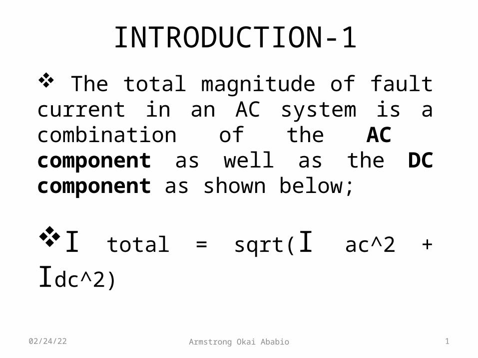
INTRODUCTION-1 The total magnitude of fault current in an AC system is a combination of the AC component as well as the DC component as shown below;
I total = sqrt(I ac^2 + Idc^2)
1Armstrong Okai Ababio05/03/23
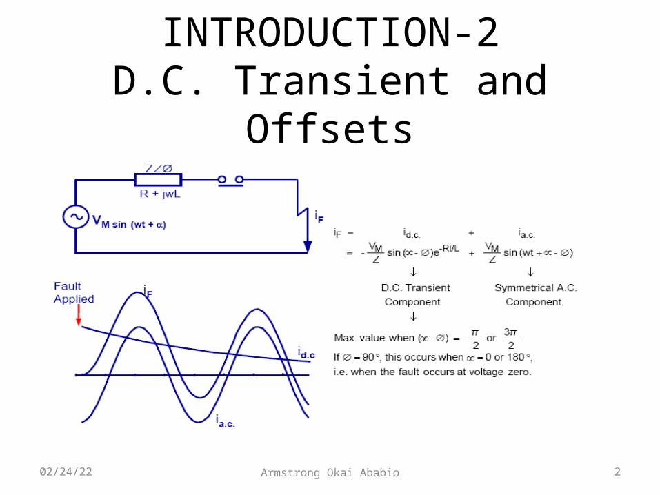
INTRODUCTION-2D.C. Transient and Offsets
2Armstrong Okai Ababio05/03/23
INTRODUCTION-3 Presently, The Short circuit levels of ECG as well as the Dimensioning of the CTs and Relays in ECG's system do not take into consideration the DC component of the fault current.
As a food for thought, The DC component at a particular point in the power system depends on the time constant of the substation under consideration.
3Armstrong Okai Ababio05/03/23

TIME CONSTANT, Tn -1 The Time constant of the power system is the X/R ratio divided by omega (w=2πf).
The higher the X/R ratio, the higher the Time Constant and the longer it takes the DC Component of the fault current to decay to zero causing wearing of Circuit Breaker contacts.
4Armstrong Okai Ababio05/03/23
TIME CONSTANT, Tn-2
The Time constant of the power system also influences the Transient Dimensioning Factor (Ktd) of the Current Transformer (CT) and Relays.
The Transient Dimensioning Factor (Ktd) of the Current Transformer (CT) and Relays is described in the following slides;
5Armstrong Okai Ababio05/03/23

TRANSIENT DIMENSIONING FACTOR (Ktd)-1The Transient Dimensioning Factor (Ktd) is a multiplier of the Accuracy Limit Factor (ALF) of the CT.
The Ktd ensures that the dimensioning of the CT to take into consideration the DC Component of the fault current in order to prevent CT saturation and possible damage to power system components.
6Armstrong Okai Ababio05/03/23
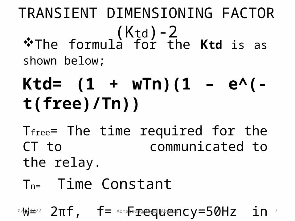
TRANSIENT DIMENSIONING FACTOR (Ktd)-2The formula for the Ktd is as shown below;
Ktd= (1 + wTn)(1 – e^(-t(free)/Tn))Tfree= The time required for the CT to
communicated to the relay.
Tn= Time Constant
W= 2πf, f= Frequency=50Hz in Ghana
7Armstrong Okai Ababio05/03/23
TRANSIENT DIMENSIONING FACTOR (Ktd)-3
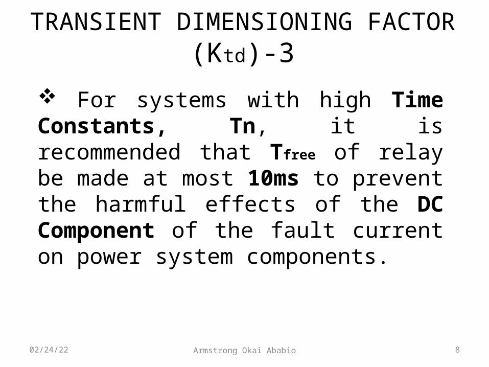
For systems with high Time Constants, Tn, it is recommended that Tfree of relay be made at most 10ms to prevent the harmful effects of the DC Component of the fault current on power system components.
8Armstrong Okai Ababio05/03/23

CASE STUDY, EARTHING TRANSFORMER AT THE ECG NEW TEMA BSP-1
The CT and Relay settings of the ECG Tema BSP before the blast of the Earthing Transformer is as shown below;300:5. 10P20,30 VA The earth fault settings on the Earthing transformer are as below: Ie > 140 A primary td = 0.35 X/R = 68.5824
Curve Type= Long Time Inverse (LTI)
9Armstrong Okai Ababio05/03/23

CASE STUDY, EARTHING TRANSFORMER AT THE ECG NEW TEMA BSP-2
From first principles, it can be explained that, for a fault current of magnitude 300A*20ALF(Primary Current*ALF=6kA), the Manufacturer can guarantee 10% Accuracy of the Current Transformer. This means that the CT will not saturate upto this limit.
This Covers the Earthing Transformer at the New Tema BSP since the Maximum fault current that can go through it is 3180A. (Ref: ECG’s Specifications).
This Presentation will reveal if this condition also encompasses the DC Component the fault current.
10Armstrong Okai Ababio05/03/23
CASE STUDY, EARTHING TRANSFORMER AT THE ECG NEW TEMA BSP-3
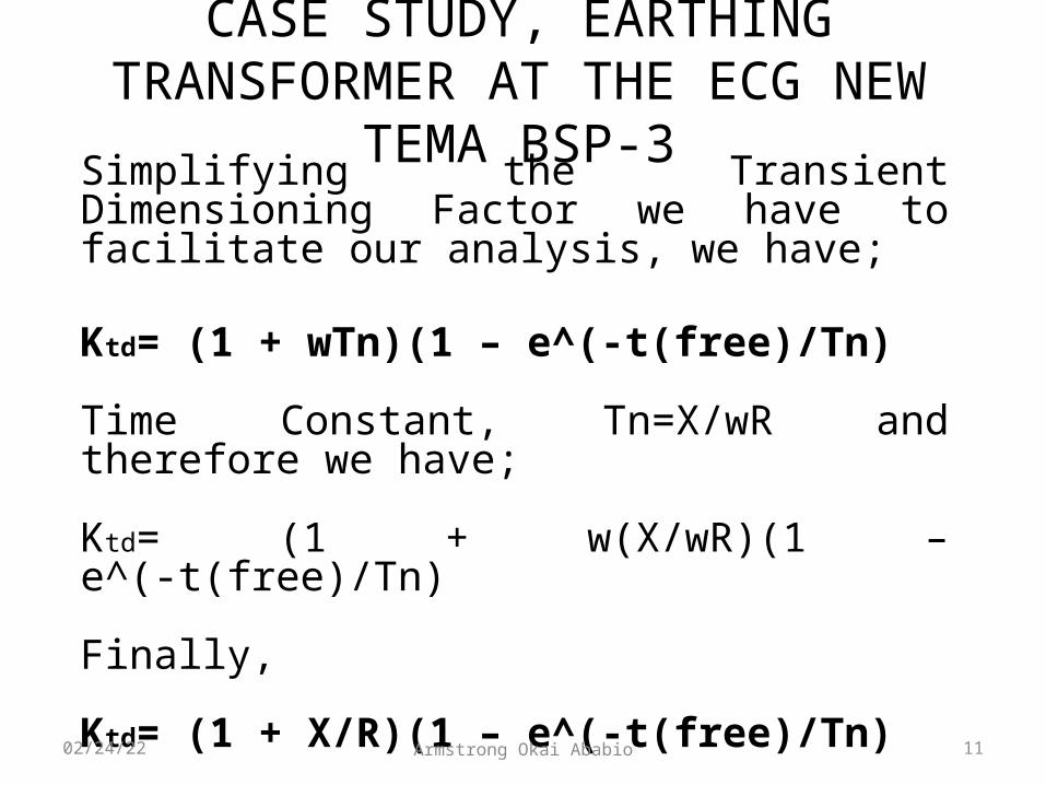
Simplifying the Transient Dimensioning Factor we have to facilitate our analysis, we have;
Ktd= (1 + wTn)(1 – e^(-t(free)/Tn)
Time Constant, Tn=X/wR and therefore we have;
Ktd= (1 + w(X/wR)(1 – e^(-t(free)/Tn)
Finally,
Ktd= (1 + X/R)(1 – e^(-t(free)/Tn)
11Armstrong Okai Ababio05/03/23

CASE STUDY, EARTHING TRANSFORMER AT THE ECG NEW TEMA BSP-4
Extracting the parameters of the Transient Dimensioning Factor from the data on the Earthing Transformer before the blast, we have;
Tfree= td=350msW= 2πf=2*π*50=100π
X/R ratio of Tema=68.5824
Tn= Time Constant=X/wR=68.5824/100π=218.3ms
Now substituting these values into the Transient Dimensioning Formula we have;
12Armstrong Okai Ababio05/03/23
CASE STUDY, EARTHING TRANSFORMER AT THE ECG NEW TEMA BSP-5
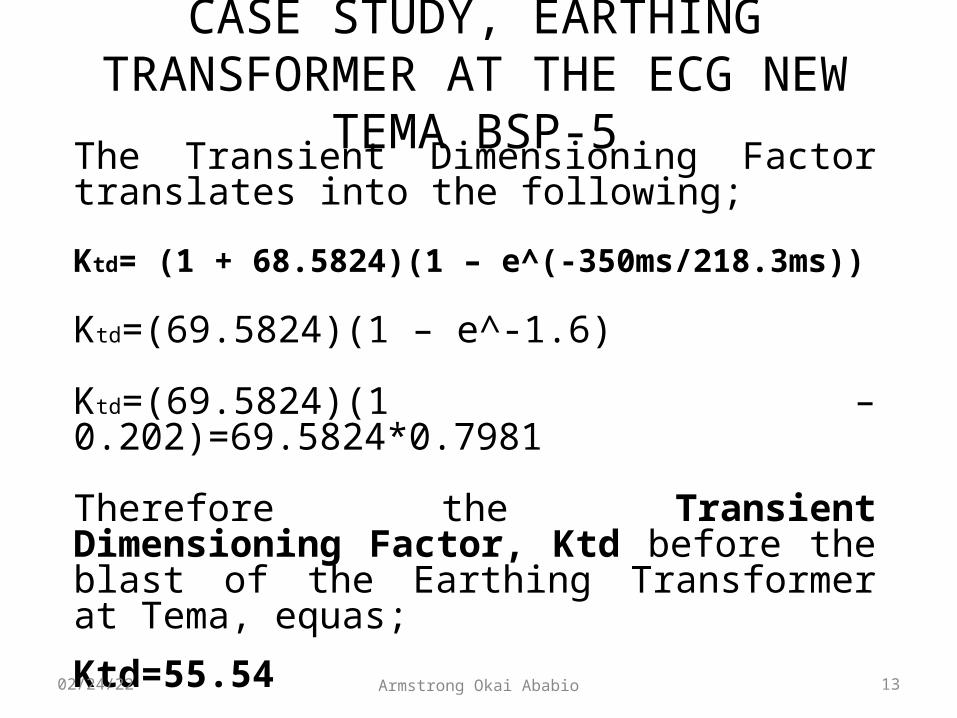
The Transient Dimensioning Factor translates into the following;
Ktd= (1 + 68.5824)(1 – e^(-350ms/218.3ms))
Ktd=(69.5824)(1 – e^-1.6)
Ktd=(69.5824)(1 – 0.202)=69.5824*0.7981
Therefore the Transient Dimensioning Factor, Ktd before the blast of the Earthing Transformer at Tema, equas;Ktd=55.54
13Armstrong Okai Ababio05/03/23

CASE STUDY, EARTHING TRANSFORMER AT THE ECG NEW TEMA BSP-6
As Discussed in the previous slides, the Transient Dimensioning Factor, Ktd is a multiplier of the Actual Actual Accuracy Limit (ALF) of the Current Transformer. This way the Transient Dimensioning Factor, Ktd ensures that the CT is dimensioned to take into consideration the DC Component of the fault current to prevent its adverse effects on power system components.
We proceed with the assumption that The rated ALF is equal to the actual ALF.
14Armstrong Okai Ababio05/03/23

CASE STUDY, EARTHING TRANSFORMER AT THE ECG NEW TEMA BSP-7
The Transient Dimensioning Factor, Ktd of the CT on the Earthing Transformer at the Tema BSP before the blast was calculated from the previous slides to be;Ktd=55.54
This means that the ALF of the 10P20, 30VA, 300:5 CT at the New Tema BSP should be multiplied by a Ktd of 55.54 (i.e. 55.54*20=1110.8)
15Armstrong Okai Ababio05/03/23
CASE STUDY, EARTHING TRANSFORMER AT THE ECG NEW TEMA BSP-8
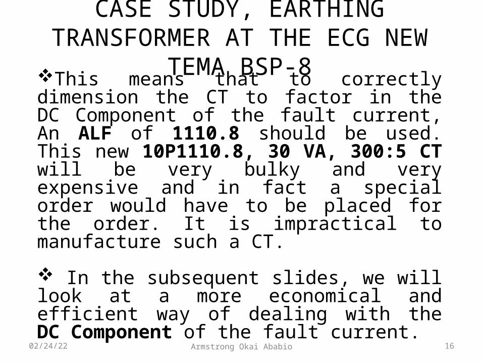
This means that to correctly dimension the CT to factor in the DC Component of the fault current, An ALF of 1110.8 should be used. This new 10P1110.8, 30 VA, 300:5 CT will be very bulky and very expensive and in fact a special order would have to be placed for the order. It is impractical to manufacture such a CT.
In the subsequent slides, we will look at a more economical and efficient way of dealing with the DC Component of the fault current.
16Armstrong Okai Ababio05/03/23

RECOMMENDED SOLUTION TO THE EARTHING TRANSFORMER BLASTS AT THE NEW TEMA BSP -1
Saturation-free transmission time (Tfree of Relay) is the time required for the CT to send a clear fault signal to the Relay for it to actuate the Circuit Breaker to isolate the faulty portion of the network. This should be as fast as possible.
Instead of a Saturation-free transmission time (Tfree of Relay) of 350ms, It is recommended that Tfree of 10ms (Thus half a cycle, Full cycle=1/50Hz=20ms) be used. This was proved by SIEMENS.
17Armstrong Okai Ababio05/03/23

RECOMMENDED SOLUTION TO THE EARTHING TRANSFORMER BLASTS AT THE NEW TEMA BSP -2
Keeping all other parameters of the Transient Dimensioning Factor, Ktd constant (i.e.X/R ratio =68.5824, Tn=218.3ms) and changing the Saturation free time of the Relay from 350ms to 10ms, we have;
Ktd= (1 + X/R)(1 – e^(-t(free)/Tn
Ktd= (1 + 68.5824)(1 – e^(-10ms/218.3ms))
Ktd= (69.5824)(1 – e^(-0.0458))=69.5824*(1-0.9552)
Ktd= 69.5824*0.04477=3.12
18Armstrong Okai Ababio05/03/23
RECOMMENDED SOLUTION TO THE EARTHING TRANSFORMER BLASTS AT THE NEW TEMA BSP -3
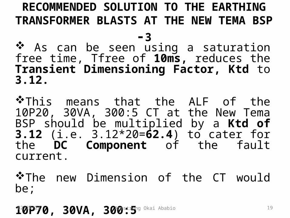
As can be seen using a saturation free time, Tfree of 10ms, reduces the Transient Dimensioning Factor, Ktd to 3.12.
This means that the ALF of the 10P20, 30VA, 300:5 CT at the New Tema BSP should be multiplied by a Ktd of 3.12 (i.e. 3.12*20=62.4) to cater for the DC Component of the fault current.
The new Dimension of the CT would be;
10P70, 30VA, 300:5
19Armstrong Okai Ababio05/03/23

RECOMMENDED SOLUTION TO THE EARTHING TRANSFORMER BLASTS AT THE NEW TEMA BSP -4
Optimizing, the secondary current of the CT can be reduced to 1A instead of 5A and the burden reduced from 30VA to 15VA since the burden of a CT with a secondary current of 1A is far less than a CT with secondary current of 5A (Burden=(I^2)Z).
This way the ALF can be made approximately 40 instead of 70.The Accuracy class can be made 5P instead of 10P to improve on the accuracy of the CT.Therefore the recommended settings of the CT taking into account the DC component would be;5P40, 400/1, 15VA instead of 5P20, 400/5, 30VA with relay tfree time of 10ms.
20Armstrong Okai Ababio05/03/23

RECOMMENDED SOLUTION TO THE EARTHING TRANSFORMER BLASTS AT THE NEW TEMA BSP -5
Therefore the recommended settings of the CT taking into account the DC component of the fault current would be;
5P40, 300/1, 15VA with a Saturation Free time of 10ms instead of 5P20, 300/5, 30VA with a Saturation free time of 350ms.
The Saturation free time of 10ms should be communicated to the manufacturer in addition to the other settings of the CT.
21Armstrong Okai Ababio05/03/23

CONCLUSION
In the Absence of Further Questions and Recommendations, we would want to bring the presentation to an end.
Thank You All for Coming. God Bless You All.!!!
Acknowledgement;
Ing. Julius K. Kpekpena/ Director of EngineeringIng. Kwadwo A. Obeng/ DM/ System PlanningIng. Godfred Mensah/ SM/ System Planning
22Armstrong Okai Ababio05/03/23