Embed Size (px)
Citation preview

DC
Axia
l Fan
s
11. Individual Specifications Standard Type 00 Standard 01~99: Custom
Sensor Type 00: Locked Rotor Alarm Signal (Standard) 01~49: Locked Rotor Alarm Signal (Custom) 50: Tachometer Signal (Standard) 51~99: Tachometer Signal (Custom)
Through Hole
Through Hole
Rib Type Flange Type
One Side Rib Type One Side Flange Type
1. Frame Size 10:25mm 12:30mm 14:35mm 16:40mm 20:50mm 21:52mm 24:60mm 28:70mm 31:80mm 36:92mm 47:119mm 50:127mm 59:150mm 68:172mm
2. Overall Length (Thickness) 04:10mm 06:15mm 08:20mm 10:25mm 12:32mm 15:38mm 20:50mm
3. Series P Series M Series N Series K Series H Series S Series F Series R Series V Series
4. Motor Function Brushless Type DCM
5. Input Voltage O: Standard Current C: Special Current D~Z: Special Current (A.B.O. are not used)
6. Termination W: Lead Wires T: Terminal (Terminal option on 3610KL and 4715KL Series)
7. Bearing B: Ball Bearing S: Sleeve Bearing
8. Speed 1<2<3<4<5<6<7<8 low high
9. Special Control Function 0: Standard Type 9: Sensor Type 7: Temperature Detecting Variable Speed Type/PWM Control Type 6: Temperature Detecting Variable Speed Type/Sensor Type 5: 2-Speed Type/Sensor Type 8: 2-Speed Type
10. Product Number Item Classification Mounting Style L: Standard Model Rib Type P: Standard Model Flange Type B: Standard Model Rib Type E: Standard Model Flange Type G: Standard Model Rib Type D: Standard Model Flange Type
Common Specifications
Common Specifications
24 10 M L – 04 W – B 1 0 – X 00 1 2 3 4 5 6 7 8 9 10 11
Vibration Test: ..................... Conforms to JIS C 60068-2-6, Amplitude: 1.5mm, Frequency 10 to 55 Hz, 1 hour in each of the X, Y and Z directions.
Shock Test: .........................Conforms to JIS C 60068-2-27, Acceleration rate: 981 m/s2*, Application time: 6ms once each in the X, Y and Z directions. Note: For the 1604KL, 1608KL, and 2406KL series, the conditions of the shock test are as follows: Acceleration rate: 500 m/s2, Application time: 11ms once each in the X, Y and Z directions.
Locked Rotor Protection : ..The motor is protected from burnout in the locked rotor condition for 72 hours at the rated voltage.
Polarity Protection : ............The fans are Reverse Polarity protected at the rated voltage.Insulation Class : ................E class (UL: Class A)Auto Restart:.......................Most fan models provide current shut-down/auto restart function under locked rotor conditions.
Notes: Additional performance requirements can be determined between manufacturer and customer, based on customer’s request. Ball bearing fans may be installed in a horizontal, vertical or angled position
1.1
Part Numbering System
NMBTC.COM / 818.341.3355
5: 24V6: 36V7: 48V9: Other
1: 5V2: 6V3: 9v4: 12V

Common Specifications
NMBTC.COM / 818.341.3355
1. Tach Signal
2. Specification
Vpsmax: +15VDC Ip max: 5mA [VLO max = 1.2V] Ta = 25˚C
DC Axial Turbo Fans
1.2
1.) When the rotor is locked at VOH position of signal, signal keeps VOH position or signal becomes to VOL position for a few seconds at any time of the auto-restart motion. 2.) When the rotor is locked at VOL position of signal, signal keeps VOL position or signal becomes to VOH position for a few seconds at any time of the auto-restart motion.
3.) T=T1+T2+T3 +T4= 1 Rotation T1=T2=T3=T4= 60/4m m:(min-1)
VDS max +15V
ID max 5mA
White Lead
Fan Motor Inside
Tach Signal Output
Black Lead
GND
Fig. 1 Tach Signal Circuit
R
3-1 (Case-1) Locked Rotor
VOH
VOL
T1 T2 T3 T4
(1 Rotation)
3-2 (Case-2)
VOH
Locked Rotor
VOL
T1 T2 T3 T4
(1 Rotation)
T
T
or
or
Warning: Improper connection of the sensor lead may cause damage to the motor drive IC. We shall be free from compensation, if trouble occurs due to insertion of opposite direction.
Common Specifications
PATENT PENDING

1.3
NMBTC.COM / 818.341.3355
General Specifications Characteristic Curves
DC
Axia
l Fan
s
Specifications
Outline
Panel Cut-Outsinch(mm)Units:
1604KL (40 X 10L)
MaterialCasing : Plastic (Black) 94V-0Impeller : Plastic (Black) 94V-0Bearing : Ball BearingLead Wire : UL1061, AWG26, +Red, -Black
Expected LifeFailure Rate: 10% 25°C 60,000 Hours (B00)
Motor Protection: Auto Restart/Polarity Protection
Insulation Resistance: 10M Ω or over with a DC500V Megger
Dielectric Withstand Voltage: AC 700V 1s
Allowable Ambient Temperature Range: -10°C ~ +70°C (Operating) -40°C ~ +70°C (Storage)
00 0.05 0.1 0.20.15 0.25
Air Flow
Stat
ic P
ress
ure
Ps
(Pa)50
40
30
20
10
(m3/min)
CFM
In H2O
B50
B40
B30
8.87.05.33.51.7
.04
.08
.12
.16
.20
8 – R3.0
AIR
.09(2.3)
.10(2.7)
NAME PLATE
1.26(32.0 0.2)
1.57(40.0 0.3)
1.26
( 32.
0 0.
2 )1.
57( 4
0.0
0.3 )
.138 4 – ( 3.5)
ROTATION
.39(10.0 0.5)
7.87
(200
) min
Rib Type Only
1.54
(39.0)
4– ( 3.5)
1.26(32.0)1.52
(38.6)
1.26
(32.
0)
1.52
(38.
6)
.138
INLET SIDE / OUTLET SIDE
Rotation: Clockwise Airflow Outlet: Air Out Over Struts *1: Average Values in Free Air
Rated Operating Current Input Speed Max. Max. Static Noise Mass
MODEL Voltage Voltage Power Air Flow Pressure
Product (V) (V) (A)*1 (W)*1 (min-1)*1 CFM*1 (m3/min)*1 in H2O (Pa)*1 (dB)*1 (g) No.
1604KL-01W-B30- X00 5 4.5 ~ 5.5 0.075 0.375 4500 4.2 0.12 .096 24.0 22.0 15
1604KL-01W-B40- X00 5 4.5 ~ 5.5 0.120 0.600 5500 5.3 0.15 .136 34.0 25.0 15
1604KL-01W-B50- X00 5 4.5 ~ 5.5 0.155 0.775 6500 6.0 0.17 .184 46.0 29.0 15
1604KL-04W-B30- X00 12 10.2 ~ 13.8 0.062 0.744 4500 4.2 0.12 .096 24.0 22.0 15
1604KL-04W-B40- X00 12 10.2 ~ 13.8 0.073 0.876 5500 5.3 0.15 .136 34.0 25.0 15
1604KL-04W-B50- X00 12 10.2 ~ 13.8 0.073 0.876 6500 6.0 0.17 .184 46.0 29.0 15
1.3

Motor Protection: Auto Restart/Polarity Protection
Insulation Resistance: 10M Ω or over with a DC500V Megger
Dielectric Withstand Voltage: AC 700V 1s
Allowable Ambient Temperature Range: -10°C ~ +70°C (Operating) -40°C ~ +70°C (Storage) (non-condensing environment)
Characteristic Curves
DC Axial Fans
1.4
NMBTC.COM / 818.341.3355
General Specifications
Specifications
1608VL (40 X 20L)
Panel Cut-Outsinch(mm)Units:
OutlineMaterialCasing : Plastic (Black) 94V-0Impeller : Plastic (Black) 94V-0Bearing : Ball BearingLead Wire : UL1007, AWG26, +Red, -Black
Expected LifeFailure Rate: 10% 25°C 50,000 Hours (B00)
Air Flow
Stat
ic P
ress
ure
Ps
(Pa)
(m3/min)
CFM
In H2O
Spee
d
P-Q Curve
Speed Curve
0.20
0
10
20
30
50
60
70
80
0.0 0.04 0.08 0.12 0.16 0.20 0.24 0.28 0.32 0.36 0.40
0 1.4 2.8 4.2 5.6 7.0 8.4 9.8 11.2 12.6 14.0
0
2000
4000
6000
8000
10000
12000
14000
B40
B50
B60
40
90
0.40 100
16000
18000
20000
0.10
0.30
B40
B50B60
1.26(32.0)1.50
(38.0)
1.26(32.0)1.50
(38.0)
1.50
(38.
0)1.
26(3
2.0)
1.50
(38.
0)1.
26(3
2.0)
OUTLET SIDEINLET SIDE
.137 (4 – 3.5)
.137 (4 – 3.5)
1.56 ( 39.8)
1.
56
(
39.8)
1.
56
(
39.8)
1.56 ( 39.8)
ROTATION
0.137(4 3.5±0.2)
1.26(32.0±0.2)
1.57(40.1±0.3)
1.26
(32 .
0±0.
2 )1.
57(4
0.0±
0.3 )
7.87
min
(200
)
0.78(20.0±0.5)
NAMEPLATE
.157(4.0)
.157(4.0)
AIRLOT NO.
Rotation: Clockwise Airflow Outlet: Air Out Over Struts *1: Average Values in Free Air
Rated Operating Current Input Speed Max. Max. Static Noise Mass
MODEL Voltage Voltage Power Air Flow Pressure
Product (V) (V) (A)*1 (W)*1 (min-1)*1 CFM*1 (m3/min)*1 in H2O (Pa)*1 (dB)*1 (g) No.
1608VL-04W-B40- BXX 12 7.0 ~ 13.2 0.08 1.02 7500 8.8 0.25 .24 58.8 29.0 40
1608VL-04W-B50- BXX 12 7.0 ~ 13.2 0.11 1.32 8500 10.2 0.29 .31 76.6 31.4 40
1608VL-04W-B60- BXX 12 7.0 ~ 13.2 0.13 1.56 9500 11.3 0.32 .40 99.3 34.6 40
1608VL-05W-B40- BXX 24 14.0 ~ 26.4 0.05 1.20 7500 8.8 0.25 .24 58.8 29.0 40
1608VL-05W-B50- BXX 24 14.0 ~ 26.4 0.07 1.68 8500 10.2 0.29 .31 76.6 31.4 40
1608VL-05W-B60- BXX 24 14.0 ~ 26.4 0.10 2.40 9500 11.3 0.32 .40 99.3 34.6 40
1.5
NMBTC.COM / 818.341.3355
General Specifications
DC
Axia
l Fan
s
Characteristic Curves
Specifications
Reference PWM Duty Vs. Speed Curve
Outline
Panel Cut-Outsinch(mm)Units:
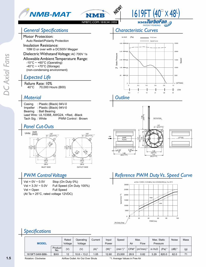
MaterialCasing : Plastic (Black) 94V-0Impeller : Plastic (Black) 94V-0Bearing : Ball BearingLead Wire : UL10368, AWG24, +Red, -BlackTach Sig. : White PWM Control : Brown
Expected LifeFailure Rate: 10% 40°C 70,000 Hours (B00)
Motor Protection: Auto Restart/Polarity Protection
Insulation Resistance: 10M Ω or over with a DC500V Megger
Dielectric Withstand Voltage: AC 700V 1s
Allowable Ambient Temperature Range: -10°C ~ +60°C (Operating) -40°C ~ +70°C (Storage) (non-condensing environment)
1619FT (40 X 48L)PATENT PENDING
NEW!
0
10000
15000
20000
25000
30000
0 20 40 60 80 100
PWM Duty
Spee
d [m
in- 1
]
at Vin=12VDC, f=25.0kHz, Vst=4.5V(Hi)/0V(Lo), Ta=25˚C
5000
min
max
0% Duty Stop
1.57
( 40)
1.26(32.0)1.51
(38.4)
1.26(32.0)1.51
(38.4)
1.51
(38.
4)1.
26(3
2.0)
1.51
(38.
4)1.
26(3
2.0)
OUTLET SIDE INLET SIDE
.137 (4 – 3.5 ±0.3)
.137 (4 – 3.5 ±0.3)
1.62
41.2 0.
11
R
2.9
Rotation: Clockwise Airflow Outlet: Air Out Over Struts *1: Average Values in Free Air
Rated Operating Current Input Speed Max. Max. Static Noise Mass
MODEL Voltage Voltage Power Air Flow Pressure
Product (V) (V) (A)*1 (W)*1 (min-1)*1 CFM*1 (m3/min)*1 in H2O (Pa)*1 (dB)*1 (g) No.
1619FT-04W-B86- BXX 12 10.8 ~ 13.2 1.05 12.60 23,000 28.9 0.82 3.29 820.0 62.0 71
.137(4 – 3.5±0.3)
1.26(32±0.3)
1.57(40.0 ±0.5)
0.197(5)
1.89(48.0 ±0.5)
1.57
(40.
0±0.
5 )1.
2632
.0± 0
.37.
88(2
00± 1
5 )
NAMEPLATE
LOT NO.
0.197(5)
ROTATION
AIR
PWM Control VoltageVst = 0V ~ 0.5V Stop (On Duty 0%)Vst = 3.3V ~ 5.0V Full Speed (On Duty 100%)Vst = Open Full Speed(At Ta = 25°C, rated voltage 12VDC)
Air Flow
Stat
ic P
ress
ure
Ps
(Pa)
(m3/min)
CFM
In H2O
0
200
400
600
800
0. 0.2 0.4 0.6 0.8 1.00
5000
10000
15000
20000
25000
Spee
d
P-Q Curve
Speed Curve
0.0 7 14 21 28 35
.80
1.60
3.20
2.40
10004.00
1.5

Motor Protection: Auto Restart/Polarity Protection
Insulation Resistance: 10M Ω or over with a DC500V Megger
Dielectric Withstand Voltage: AC 700V 1s
Allowable Ambient Temperature Range: -10°C ~ +70°C (Operating) -40°C ~ +70°C (Storage) (non-condensing environment)
Characteristic Curves
NMBTC.COM / 818.341.3355
General Specifications
DC Axial Fans
Specifications
Panel Cut-Outsinch(mm)Units:
OutlineMaterialCasing : Plastic (Black) 94V-0Impeller : Plastic (Black) 94V-0Bearing : Ball BearingLead Wire : UL3385, AWG26, +Red, -Black
Expected LifeFailure Rate: 10% 25°C 100,000 Hours (B00/E00)
2410SB (60 X 25L)
ROTATION
0.169(4 3±0.2)
1.97(50.0±0.3)
2.36(60.0 ±0.5)
2.36
(60 .
0±0.
5 )1.
97(5
0.0±
0.3 )
11.8
min
(300
)
.98(25.0±0.5)
NAMEPLATE
.157(4.0)
.157(4.0)
AIR
1.97(50.0)2.28
(58.0)
1.97(50.0)2.28
(58.0)
2.28
(58.
0)1.
97(5
0.0)
OUTLET SIDEINLET SIDE
.169 (4 – 4.3)
2.56
( 6
5.0)
2.56
( 6
5.0)
2.28
(58.
0)1.
97(5
0.0)
.169 (4 – 4.3)
Air Flow
Spee
d
P-Q Curve
Speed Curve
Stat
ic P
ress
ure
Ps
(Pa)
(m3/min)
CFM
In H2O
B20
B30
B40
B50
B20
B30
B40
B50
50
.75
0.00
0.06
0.15
0.20
0.35
0.30
0.25
0.10
0.00 0
.14 .28 .56 .42 .70
1000
2000
3000
4000
5000
6000
7000
0.00 5.0 10.0 20.015.0 25.0
25
Rotation: Clockwise Airflow Outlet: Air Out Over Struts *1: Average Values in Free Air
Rated Operating Current Input Speed Max. Max. Static Noise Mass
MODEL Voltage Voltage Power Air Flow Pressure
Product (V) (V) (A)*1 (W)*1 (min-1)*1 CFM*1 (m3/min)*1 in H2O (Pa)*1 (dB)*1 (g) No.
2410SB-04W-B20 B/EXX 12 6 ~ 13.8 0.06 0.72 3000 14.5 0.41 0.10 26 17.0 56
2410SB-04W-B30 B/EXX 12 6 ~ 13.8 0.08 0.96 3500 16.9 0.48 0.14 35 22.5 56
2410SB-04W-B40 B/EXX 12 6 ~ 13.8 0.10 1.20 4000 19.8 0.56 0.18 46 26.5 56
2410SB-04W-B50 B/EXX 12 6 ~ 13.8 0.15 1.80 4700 23.3 0.66 0.25 63 32.0 56
2410SB-05W-B20 B/EXX 24 12.0 ~ 27.6 0.03 0.72 3000 14.5 0.41 0.10 26 17.0 56
2410SB-05W-B30 B/EXX 24 12.0 ~ 27.6 0.04 0.96 3500 16.9 0.48 0.14 35 22.5 56
2410SB-05W-B40 B/EXX 24 12.0 ~ 27.6 0.06 1.44 4000 19.8 0.56 0.18 46 26.5 56
2410SB-05W-B50 B/EXX 24 12.0 ~ 27.6 0.08 1.92 4700 23.3 0.66 0.25 63 32.0 56
1.6

Motor Protection: Auto Restart/Polarity Protection
Insulation Resistance: 10M Ω or over with a DC500V Megger
Dielectric Withstand Voltage: AC 700V 1s
Allowable Ambient Temperature Range: -10°C ~ +70°C (Operating) -40°C ~ +70°C (Storage) (non-condensing environment)
1.7
NMBTC.COM / 818.341.3355
General Specifications
DC
Axia
l Fan
s
Characteristic Curves
1.7
Specifications
Panel Cut-Outsinch(mm)Units:
OutlineMaterialCasing : Plastic (Black) 94V-0Impeller : Plastic (Black) 94V-0Bearing : Ball BearingLead Wire : UL3385, AWG26, +Red, -Black
Expected LifeFailure Rate: 10% 25°C 100,000 Hours (B00/E00)
3110SB (80 X 25L)
Air Flow
Stat
ic P
ress
ure
Ps
(Pa)
(m3/min)
CFM
In H2O
Spee
d
P-Q Curve
Speed Curve
0.0
5.0
10.0
15.0
20.0
25.0
30.0
35.0
40.0
0.0 0.5 1.00
500
1000
1500
2000
2500
3000
3500
4000
B50
B40
B20
B30
B50
B40
B30
B20
0.0 5.0 10.0 15.0 20.0 25.0 30.0 35.0 40.0 45.0
0.00
0.02
0.04
0.06
0.08
0.10
0.12
0.14
0.16
ROTATION0.169
(4 4.3±0.2)
2.81(71.5±0.3)
3.15(80.0 ±0.5)
3.15
(80 .
0±0.
5 )2.
81(7
1.5±
0.3 )
11.8
min
(300
)
0.98(25.0±0.5)
NAMEPLATE
.157(4.0)
.157(4.0)
AIR
2.81(71.5)3.02
(76.8)
2.81
(71.
5)3.
02(7
6.8)
OUTLET SIDEINLET SIDE
.169 (4 – 4.3)
.169 (4 – 4.3)
3.34
( 85.0)
2.81(71.5)3.02
(76.8)
2.81
(71.
5)3.
02(7
6.8)
3.38
( 86.0)
Rotation: Clockwise Airflow Outlet: Air Out Over Struts *1: Average Values in Free Air
Rated Operating Current Input Speed Max. Max. Static Noise Mass
MODEL Voltage Voltage Power Air Flow Pressure
Product (V) (V) (A)*1 (W)*1 (min-1)*1 CFM*1 (m3/min)*1 in H2O (Pa)*1 (dB)*1 (g) No.
3110SB-04W-B20 B/EXX 12 6 ~ 13.8 0.05 0.60 2000 26.1 0.74 0.07 16.5 19.0 80
3110SB-04W-B30 B/EXX 12 6 ~ 13.8 0.06 0.72 2300 30.4 0.86 0.09 21.5 22.0 80
3110SB-04W-B40 B/EXX 12 6 ~ 13.8 0.09 1.08 2700 36.0 1.02 0.12 29.0 26.0 80
3110SB-04W-B50 B/EXX 12 6 ~ 13.8 0.14 1.68 3100 41.3 1.17 0.15 37.5 30.0 80
3110SB-05W-B20 B/EXX 24 12.0 ~ 27.6 0.03 0.72 2000 26.1 0.74 0.07 16.5 19.0 80
3110SB-05W-B30 B/EXX 24 12.0 ~ 27.6 0.04 0.96 2300 30.4 0.86 0.09 21.5 22.0 80
3110SB-05W-B40 B/EXX 24 12.0 ~ 27.6 0.06 1.44 2700 36.0 1.02 0.12 29.0 26.0 80
3110SB-05W-B50 B/EXX 24 12.0 ~ 27.6 0.08 1.92 3100 41.3 1.17 0.15 37.5 30.0 80

Motor Protection: Auto Restart/Polarity Protection
Insulation Resistance: 10M Ω or over with a DC500V Megger
Dielectric Withstand Voltage: AC 700V 1s
Allowable Ambient Temperature Range: -10°C ~ +70°C (Operating) -40°C ~ +70°C (Storage) (non-condensing environment)
Characteristic Curves
DC Axial Fans
1.8
NMBTC.COM / 818.341.3355
General Specifications
Specifications
Panel Cut-Outsinch(mm)Units:
OutlineMaterialCasing : Plastic (Black) 94V-0Impeller : Plastic (Black) 94V-0Bearing : Ball BearingLead Wire : UL3385, AWG26, +Red, -Black
Expected LifeFailure Rate: 10% 25°C 100,000 Hours (B00/E00)
3610SB (92 X 25L)
Air Flow
Stat
ic P
ress
ure
Ps
(Pa)
(m3/min)
CFM
In H2O
P-Q Curve
Speed Curve
0.00
0.04
0.08
0.12
0.16
0.20
0.24
0
10
20
30
40
50
60
0.0 7.0 14.0 21.0 28.0 35.0 42.0 49.0 56.0 63.0
Spee
d
B50
B40
B40
B30
B30
B20
B20
B50
0.0 0.2 0.4 0.6 0.8 1.0 1.2 1.4 1.6 1.8
0
1000
2000
3000
4000
5000
6000
ROTATION
.169(4 4.3±0.2)
3.25(82.5±0.3)
3.62(92.0 ±0.5)
3.62
(92 .
0±0.
5 )3.
25(8
2.5±
0.3 )
11.8
min
(300
)
0.98(25.0±0.5)
NAME
PLATE
.157(4.0)
.157(4.0)
AIR
4.09
(10
4.0)
3.25(82.5)3.53
(89.6)
3.25(82.5)3.53
(89.6)
3.25
(82.
5)3.
53(8
9.6)
3.25
(82.
5)3.
53(8
9.6)
OUTLET SIDEINLET SIDE
.169 (4 – 4.3)
.169 (4 – 4.3)
3.94
( 1
00.0)
Rotation: Clockwise Airflow Outlet: Air Out Over Struts *1: Average Values in Free Air
Rated Operating Current Input Speed Max. Max. Static Noise Mass
MODEL Voltage Voltage Power Air Flow Pressure
Product (V) (V) (A)*1 (W)*1 (min-1)*1 CFM*1 (m3/min)*1 in H2O (Pa)*1 (dB)*1 (g) No.
3610SB-04W-B20- B/EXX 12 6 ~ 13.8 0.07 0.84 2050 35.7 1.01 0.09 21.5 25.0 95
3610SB-04W-B30- B/EXX 12 6 ~ 13.8 0.10 1.20 2400 41.3 1.17 0.12 29.5 28.0 95
3610SB-04W-B40- B/EXX 12 6 ~ 13.8 0.13 1.56 2750 48.4 1.37 0.15 38.4 32.0 95
3610SB-04W-B50- B/EXX 12 6 ~ 13.8 0.15 1.80 3100 54.4 1.54 0.19 47.9 35.0 95
3610SB-05W-B20- B/EXX 24 12 ~ 27.6 0.04 0.84 2050 35.7 1.01 0.09 21.5 25.0 95
3610SB-05W-B30- B/EXX 24 12 ~ 27.6 0.05 1.20 2400 41.3 1.17 0.12 29.5 28.0 95
3610SB-05W-B40- B/EXX 24 12 ~ 27.6 0.07 1.56 2750 48.4 1.37 0.15 38.4 32.0 95
3610SB-05W-B50- B/EXX 24 12 ~ 27.6 0.08 1.80 3100 54.4 1.54 0.19 47.9 35.0 95

Motor Protection: Auto Restart/Polarity Protection
Insulation Resistance: 10M Ω or over with a DC500V Megger
Dielectric Withstand Voltage: AC 700V 1s
Allowable Ambient Temperature Range: -10°C ~ +70°C (Operating) -40°C ~ +70°C (Storage) (non-condensing environment)
1.9
NMBTC.COM / 818.341.3355
General Specifications
DC
Axia
l Fan
s
Characteristic Curves
1.9
Specifications
Panel Cut-Outsinch(mm)Units:
OutlineMaterialCasing : Plastic (Black) 94V-0Impeller : Plastic (Black) 94V-0Bearing : Ball BearingLead Wire : UL3385, AWG26, +Red, -Black
Expected LifeFailure Rate: 10% 25°C 100,000 Hours (B00/E00)
3610VL (92 X 25L)
Air Flow
Stat
ic P
ress
ure
Ps
(Pa)
(m3/min)
CFM
In H2O
0
50
100
150
0.0 1.0 2.0 3.00
1500
3000
4500
6000
Spee
d
P-Q Curve
Speed Curve
0.0 35 70 105
.20
.60
.40
200.80
B20
B50
B30
B40
B60
B70
B20
B50B30 B40 B60 B70
ROTATION
0.169(4 4.3±0.2)
3.25(82.5±0.3)
3.62(92.0 ±0.5)
3.25
(82 .
5±0.
3 )3.
62(9
2.0±
0.5 )
11.8
min
(300
)
.98(25.0±0.5)
NAMEPLATE
AIR
LOT NO.
3.25(82.5)3.62
(89.0)
3.25(82.5)3.62
(89.0)
3.25
(82.
5)3.
62(8
9.0)
3.25
(82.
5)3.
62(8
9.0)
OUTLET SIDEINLET SIDE
.169 (4 – 4.3)
.169 (4 – 4.3)
3.
70
(
94)
4.
13
(
105)
Rotation: Clockwise Airflow Outlet: Air Out Over Struts *1: Average Values in Free Air
Rated Operating Current Input Speed Max. Max. Static Noise Mass
MODEL Voltage Voltage Power Air Flow Pressure
Product (V) (V) (A)*1 (W)*1 (min-1)*1 CFM*1 (m3/min)*1 in H2O (Pa)*1 (dB)*1 (g) No.
3610VL-04W-B20- B/EXX 12 7.0 ~ 13.8 0.18 2.16 3200 54.0 1.53 .20 50 35.5 135
3610VL-04W-B30- B/EXX 12 7.0 ~ 13.8 0.24 2.88 3600 61.1 1.73 .26 65 38.5 135
3610VL-04W-B40- B/EXX 12 7.0 ~ 13.8 0.30 3.60 4000 68.1 1.93 .32 80 42.0 135
3610VL-04W-B50- B/EXX 12 7.0 ~ 13.8 0.40 4.80 4500 77.0 2.18 .39 98 45.0 135
3610VL-04W-B60- B/EXX 12 7.0 ~ 13.8 0.52 6.24 5000 85.8 2.43 .48 120 48.0 135
3610VL-04W-B70- B/EXX 12 7.0 ~ 13.8 0.72 8.64 5600 96.4 2.73 .60 150 51.0 135
3610VL-05W-B20- B/EXX 24 14.0 ~ 27.6 0.11 2.64 3200 54.0 1.53 .20 50 35.5 135
3610VL-05W-B30- B/EXX 24 14.0 ~ 27.6 0.14 3.36 3600 61.1 1.73 .26 65 38.5 135
3610VL-05W-B40- B/EXX 24 14.0 ~ 27.6 0.17 4.08 4000 68.1 1.93 .32 80 42.0 135
3610VL-05W-B50- B/EXX 24 14.0 ~ 27.6 0.22 5.28 4500 77.0 2.18 .39 98 45.0 135
3610VL-05W-B60- B/EXX 24 14.0 ~ 27.6 0.28 6.72 5000 85.8 2.43 .48 120 48.0 135
3610VL-05W-B70- B/EXX 24 14.0 ~ 27.6 0.38 9.12 5600 96.4 2.73 .60 150 51.0 135

Characteristic Curves
DC Axial Fans
1.10
NMBTC.COM / 818.341.3355
General Specifications
Specifications
Panel Cut-Outsinch(mm)Units:
OutlineMaterialCasing : Plastic (Black) 94V-0Impeller : Plastic (Black) 94V-0Bearing : Ball BearingLead Wire : UL1007, AWG24, +Red, -Black
Motor Protection: Auto Restart/Polarity Protection
Insulation Resistance: 10M Ω or over with a DC500V Megger
Dielectric Withstand Voltage: AC 700V 1s
Allowable Ambient Temperature Range: B50 Class: -10°C ~ +40°C (Operating) B10 ~ B40 Class: -10°C ~ +70°C (Operating) B10 ~ B40 Class: -40°C ~ +70°C (Storage) B50 Class: -40°C ~ +60°C (Storage) (non-condensing environment)
Expected LifeFailure Rate: 10% 25°C 50,000 Hours (P00)
4715KL (119 X 38L)
4.13
( 105
.0)
4.51
( 114
.5)
4.13(105.0)
4.51(114.5)
4.88
( 124.0
)
OUTLET SIDEINLET SIDE
4.13
( 105
.0)
4.51
( 114
.5)
4.13(105.0)
4.51(114.5)
4.96
( 126.0
)
.1694 – ( 4.3±0.2)
.1694 – ( 4.3±0.2)
NAMEPLATE
AIR
ROTATION
4.69(119.0±0.5)
1.5(38.4±0.5)
4.13(105.0±0.5)
4.69
( 119
.0 ±
0.5 )
4.13
( 105
.0 ±
0.5 )
11.8
(300
) min
.1698 – ( 4.3±0.2)
.08
12417.6 35.3 53 71 88 106
.16
.24
.32
.48
CFM
In H2O
B40
B50
B30
B20
B10
Rotation: Clockwise Airflow Outlet: Air Out Over Struts *1: Average Values in Free Air
** Contact NMB for availability
**
Rated Operating Current Input Speed Max. Max. Static Noise Mass
MODEL Voltage Voltage Power Air Flow Pressure
Product (V) (V) (A)*1 (W)*1 (min-1)*1 CFM*1 (m3/min)*1 in H2O (Pa)*1 (dB)*1 (g) No.
4715KL-04W-B10- X00 12 6.0 ~ 13.8 0.27 3.24 2300 83.6 2.37 .17 44.1 37.0 260
4715KL-04W-B20- X00 12 6.0 ~ 13.8 0.40 4.80 2650 97.0 2.75 .22 55.9 41.0 260
4715KL-04W-B30- X00 12 6.0 ~ 13.8 0.55 6.60 2950 108.0 3.07 .27 68.2 42.5 260
4715KL-04W-B40- X00 12 6.0 ~ 13.8 0.70 8.40 3200 118.0 3.34 .33 81.4 46.5 260
4715KL-04W-B50- X00 12 9.5 ~ 12.6 1.00 12.00 3600 129.9 3.68 .44 110.0 50.0 260
4715KL-05W-B10- X00 24 10.0 ~ 27.6 0.15 3.60 2300 83.6 2.37 .17 44.1 37.0 260
4715KL-05W-B20- X00 24 10.0 ~ 27.6 0.21 5.04 2650 97.0 2.75 .22 55.9 41.0 260
4715KL-05W-B30- X00 24 10.0 ~ 27.6 0.31 7.44 2950 108.0 3.07 .27 68.2 42.5 260
4715KL-05W-B40- X00 24 10.0 ~ 27.6 0.35 8.40 3200 118.0 3.34 .33 81.4 46.5 260
4715KL-05W-B50- X00 24 18.0 ~ 25.0 0.50 12.00 3600 130.0 3.68 .44 110.0 50.0 260
4715KL-07W-B10- X00 48 25.0 ~ 55.2 0.08 3.84 2300 83.6 2.37 .17 44.1 37.0 260
4715KL-07W-B20- X00 48 25.0 ~ 55.2 0.11 5.28 2650 97.0 2.75 .22 55.9 41.0 260
4715KL-07W-B30- X00 48 25.0 ~ 55.2 0.16 7.68 2950 108.0 3.07 .27 68.2 42.5 260
4715KL-07W-B40- X00 48 25.0 ~ 55.2 0.20 9.60 3200 118.0 3.34 .33 81.4 46.5 260
4715KL-07W-B50- X00 48 30.0 ~ 60.0 0.16 7.68 3600 130.0 3.68 .44 110.0 50.0 260

1.11
NMBTC.COM / 818.341.3355
General Specifications
DC
Axia
l Fan
s
Characteristic Curves
1.11
Specifications
Panel Cut-Outsinch(mm)Units:
OutlineMaterialCasing : Plastic (Black) 94V-0Impeller : Plastic (Black) 94V-0Bearing : Ball BearingLead Wire : UL1007, AWG26, +Red, -Black
Motor Protection: Auto Restart/Polarity Protection
Insulation Resistance: 10M Ω or over with a DC500V Megger
Dielectric Withstand Voltage: AC 700V 1s
Allowable Ambient Temperature Range: B50, B40 Class: -10°C ~ +45°C (Operating) B30 Class: -10°C ~ +50°C (Operating) All Class: -40°C ~ +60°C (Storage)
Expected LifeFailure Rate: 10% 25°C 100,000 Hours (R00)
4715KL (119 X 38L)3 BLADE
4.13
( 105
.0)
4.51
( 114
.5)
4.13(105.0)
4.51(114.5)
4.88
( 124.0
)
OUTLET SIDEINLET SIDE
4 – ( 4.3 ±0.2).169
4 – ( 4.3 ±0.2).169
4.13
( 105
.0)
4.51
( 114
.5)
4.13(105.0)
4.51(114.5)
4.96
( 126.0
)
±0.2)
AIR NAMEPLATE
Flange Type
ROTATION
4.69(119.0 ±0.5)
1.5(38.4 ±0.5)
4.13(105.0 ±0.5)
4.69
( 119
.0 ±
0.5 )
4.13
( 105
.0 ±
0.5 )
11.8
(300
) min
.1698 – ( 4.3 ±0.2)
0
20
40
60
80
100
120
0 1 2 3
(Pa)
(m3/min)
Stat
ic P
ress
ure
Ps
Air Flow
B30
B40
B50
Rotation: Clockwise Airflow Outlet: Air Out Over Struts *1: Average Values in Free Air
** Contact NMB for availability
******
Rated Operating Current Input Speed Max. Max. Static Noise Mass
MODEL Voltage Voltage Power Air Flow Pressure
Product (V) (V) (A)*1 (W)*1 (min-1)*1 CFM*1 (m3/min)*1 in H2O (Pa)*1 (dB)*1 (g) No.
4715KL-04W-B50- R00 12 9.5 ~ 12.6 0.85 10.2 3900 132.0 3.73 .45 113.0 54.0 260
4715KL-05W-B50- R00 24 20.0 ~ 25.0 0.48 11.5 3900 132.0 3.73 .45 113.0 54.0 260
4715KL-07W-B30- R00 48 25.0 ~ 55.2 0.13 6.24 3100 105.0 2.97 .30 74.0 47.0 260
4715KL-07W-B40- R00 48 25.0 ~ 50.4 0.16 7.68 3500 121.0 3.44 .39 97.5 51.0 260
4715KL-07W-B50- R00 48 36.0 ~ 50.0 0.20 9.60 3900 132.0 3.73 .45 113.0 54.0 260

Characteristic Curves
DC Axial Fans
1.12
NMBTC.COM / 818.341.3355
General Specifications
Panel Cut-Outsinch(mm)Units:
Outline
Specifications
MaterialCasing : Plastic (Black) 94V-0Impeller : Plastic (Black) 94V-0Bearing : Ball BearingLead Wire : UL1061, AWG24, +Red, -Black
Expected LifeFailure Rate: 10% 25°C 100,000 Hours (E00)
4715VL (120 X 38L)
Motor Protection: Auto Restart/Polarity Protection
Insulation Resistance: 10M Ω or over with a DC500V Megger
Dielectric Withstand Voltage: AC 700V 1s
Allowable Ambient Temperature Range: -10°C ~ +70°C (Operating) -40°C ~ +70°C (Storage) (non-condensing environment)
Air Flow
Stat
ic P
ress
ure
Ps
(Pa)
(m3/min)
CFM
In H2O
Spee
d
P-Q Curve
Speed Curve
0
50
100
150
200
250
300
350
400
0.00
0.20
0.40
0.60
0.80
1.00
1.20
1.40
1.60
1.68 3.36 4.48 5.60 6.72k
0 20 40 60 80 100 120 140 160 180 200 220 240 260
0
1000
2000
3000
4000
5000
6000
7000
8000
B60
B60B70
B70
B80
B80
0 1.12
ROTATION
.169(8 4.3±0.3)
4.13(105.0±0.5)
4.72(120.0 ±0.5)
4.13
(105
.0± 0
.5)
4.72
(120
.0± 0
.5)
11.8
min
(300
)
1.49(38.0±0.5)
NAMEPLATE
.197(5.0 )
.197(5.0 )
AIR
LOT NO.5.00
(127)
4.63(117.6)
4.63
(117
.6)
4.63
(117
.6)
4.13
(105
.0)
OUTLET SIDEINLET SIDE
.169 (4 – 4.3)
.169 (4 – 4.3)
4.63(117.6)
4.13(105.0)
4.13(105.0)
5.43
(138)
4.13
(105
.0)
Rotation: Clockwise Airflow Outlet: Air Out Over Struts *1: Average Values in Free Air
Rated Operating Current Input Speed Max. Max. Static Noise Mass
MODEL Voltage Voltage Power Air Flow Pressure
Product (V) (V) (A)*1 (W)*1 (min-1)*1 CFM*1 (m3/min)*1 in H2O (Pa)*1 (dB)*1 (g) No.
4715VL-04W-B60- EXX 12 10.0 ~ 13.8 1.50 18.00 5000 189.9 5.38 0.92 229 59.5 370
4715VL-04W-B70- EXX 12 10.0 ~ 13.8 2.25 27.00 5700 215.7 6.11 1.15 287 63.0 370
4715VL-04W-B80- EXX 12 10.0 ~ 12.6 3.00 36.00 6400 243.2 6.89 1.46 363 66.0 370
4715VL-05W-B50- EXX 24 18.0 ~ 27.6 0.76 18.24 4700 182.5 5.17 0.83 207 55.5 370
4715VL-05W-B60- EXX 24 18.0 ~ 27.6 0.74 17.76 5000 189.9 5.38 0.92 229 59.5 370
4715VL-05W-B70- EXX 24 18.0 ~ 27.6 1.04 24.96 5700 215.7 6.11 1.15 287 63.0 370
4715VL-05W-B80- EXX 24 18.0 ~ 27.6 1.48 35.52 6400 243.2 6.89 1.46 363 66.0 370
4715VL-07W-B50- EXX 48 40.0 ~ 52.8 0.37 17.80 4700 182.5 5.17 0.83 207 55.5 370
4715VL-07W-B60- EXX 48 40.0 ~ 55.2 0.45 21.60 5000 189.9 5.38 0.92 229 59.5 370
4715VL-07W-B70- EXX 48 40.0 ~ 55.2 0.60 28.80 5700 215.7 6.11 1.15 287 63.0 370
4715VL-07W-B80- EXX 48 40.0 ~ 52.0 0.80 38.40 6400 243.2 6.89 1.46 363 66.0 370

Motor Protection: Auto Restart/Polarity Protection
Insulation Resistance: 10M Ω or over with a DC500V Megger
Dielectric Withstand Voltage: AC 700V 1s
Allowable Ambient Temperature Range: -10°C ~ +70°C (Operating) -40°C ~ +70°C (Storage) (non-condensing environment)
1.13
NMBTC.COM / 818.341.3355
General Specifications
DC
Axia
l Fan
s
Characteristic Curves
1.13
Panel Cut-Outsinch(mm)Units:
Outline
Specifications
MaterialCasing : Plastic (Black) 94V-0Impeller : Plastic (Black) 94V-0Bearing : Ball BearingLead Wire : UL1007, AWG26, +Red, -Black
Expected LifeFailure Rate: 10% 25°C 100,000 Hours (D00)
5920VL (150 X Ø172 X 50L)
Air Flow
Stat
ic P
ress
ure
Ps
(Pa)
(m3/min)
CFM
In H2O
5000
10000
15000
20000
25000
P-Q Curve
0
50
100
150
200
250
0.20
0.00
0.40
0.60
0.80
1.00
0 2 4 6 8 10
0 50 100 150 200 250 300 350
ROTATION
.169(8 4.3±0.2)
5.90(150)
.554-(14.0)
6.77
(17
2 ).5
5(1
4.0 )
6.38
(162
.0± 0
.6)
11.8
min
(300
)
2.0(50.8±0.2)
NAMEPLATE
.37(9.4)
.37(9.4)
2.18
(55.5˚)
2.18(55.5˚)
AIR
LOT NO.
.
OUTLET SIDEINLET SIDE
.55 4 – (14)
.1774 – ( 4.5)
.177 4 – ( 4.5)
.39
4 –
()
.177 4 – ( 4.5)
5.75(146)
5.75(146)
6.38
(162± 0.2)
6.38
(162± 0.2)
6.54
(16
6±0.2
)
5.94
(15
1)
2.18
(55.5˚)
2.18(55.5˚) 2.18
(55.5˚)
2.18(55.5˚)
.
Rotation: Counterclockwise Airflow Outlet: Air Out Over Struts *1: Average Values in Free Air
Rated Operating Current Input Speed Max. Max. Static Noise Mass
MODEL Voltage Voltage Power Air Flow Pressure
Product (V) (V) (A)*1 (W)*1 (min-1)*1 CFM*1 (m3/min)*1 in H2O (Pa)*1 (dB)*1 (g) No.
5920VL-07W-B10- DXX 48 36 ~ 56 0.28 13.44 2550 194.5 5.51 .43 106 51.0 830
5920VL-07W-B20- DXX 48 36 ~ 56 0.33 15.84 2850 213.2 6.04 .53 131 54.0 830
5920VL-07W-B30- DXX 48 36 ~ 56 0.37 17.76 3150 236.5 6.70 .61 152 57.0 830
5920VL-07W-B40- DXX 48 36 ~ 56 0.41 19.68 3350 251.0 7.11 .67 167 59.0 830
5920VL-07W-B50- DXX 48 36 ~ 56 0.44 21.10 3500 263.3 7.46 .74 184 61.0 830
5920VL-07W-B60- DXX 48 36 ~ 56 0.52 25.00 3750 283.1 8.02 .85 211 63.0 830