Embed Size (px)
Citation preview

LOWER WESTCHESTER BRIDGEBUNDLE
PIN 8101.46, Contract D900049
DB CONTRACT DOCUMENTSPART 8
SPECIAL SPECIFICATIONS
Draft September 16, 2019

New York State Department of Transportation
Lower Westchester Bridge Bundle i Part 8 - Special SpecificationsPIN 8101.46, Contract D900049 Draft September 16, 2019
This Part 8 – Special Specifications provides access to, and details the Project-specificrequirements for the use of, the following documents:
1. NYSDOT Standard Specifications and Construction Materials2. NYSDOT Engineering Information Issuances3. NYSDOT Special Specifications.
NYSDOT Standard Specifications and Construction Materials
The Design-Builder shall use the NYSDOT Standard Specifications Construction Materials incoordination with Part 5 – Special Provisions.
The NYSDOT Standard Specifications Construction Materials can be accessed at the followinginternet link:
https://www.dot.ny.gov/main/business-center/engineering/specifications/busi-e-standards-usc.
NYSDOT Engineering Information Issuances
The Design-Builder shall use the relevant NYSDOT engineering information issuances, whichinclude:
1. Engineering Instructions (EI);2. Engineering Bulletins (EB);3. Engineering Directives (ED).
The above listed engineering information issuances can be accessed at the following internetlink:
https://www.dot.ny.gov/main/business-center/consultants/forms-publications-and-instructions/engineering-information-issuance-system
NYSDOT Special Specifications
The Design-Builder may use NYSDOT Special Specifications which are listed in the ElectronicPay Item Catalog (e-PIC) and which have received General Approval, and shall use anyNYSDOT Special Specifications which are referenced in this Part 8 or elsewhere in the ContractDocuments. Delete and ignore sections in the NYSDOT Special Specifications titled Method ofMeasurement and Basis of Payment from the NYSDOT Special Specifications.
NYSDOT Special Specifications can be accessed at the following internet link:
https://www.dot.ny.gov/main/business-center/engineering/specifications/special-specifications-us.
The NYSDOT e-PIC may be accessed at the following internet link:
https://www.dot.ny.gov/pic

New York State Department of Transportation
Lower Westchester Bridge Bundle ii Part 8 - Special SpecificationsPIN 8101.46, Contract D900049 Draft September 16, 2019
The following Special Specifications are attached herein:
ITEM 557.25000016 – CRACK SEALING USING HIGH MOLECULAR WEIGHTMETHACRYLATE – LINEAR CRACKSITEM 557.26000016 – CRACK SEALING USING HIGH MOLECULAR WEIGHTMETHACRYLATE – FLOODINGITEM 611.19010024 – POST-PLANTING CARE WITH REPLACEMENT – MAJORDECIDUOUS TREESITEM 617.11000024 – EQUIPMENT CLEANING FOR INVASIVE PLANT SPECIESITEM 634.99010017 – BUILDING CONDITION SURVEYITEM 662.1710NN08 – INSTALL STEEL CONDUIT ON STRUCTURE (ELECTRIC)ITEM 662.8101NN08 – INSTALL STEEL GAS MAIN PIPE ON STRUCTURE (CONEDISON)ITEM 662.02010011 – CON EDISON ELECTRIC DUCTSITEM 662.12010039 – FURNISH AND INSTALL FIBERGLASS CONDUIT &SUPPORTSITEM 662.83310008 – INSTALL STEEL GAS MAIN PIPE OFF STRUCTURE (CONEDISON)ITEM 680.18010011 – 75 FOOT CAMERA POLE WITH 2 LOWERING DEVICESITEM 680.80324515 – INSTALL MICROCOMPUTER CABINETITEM 680.81500010 – PEDESTRIAN COUNT-DOWN TIMER MODULEITEM 680.94997008 – FURNISH AND INSTALL ELECTRICALDISCONNECT/GENERATOR TRANSFER SWITCHITEM 680.95020615 – SERVICE CABLE 2 CONDUCTOR, NO. 06 AWGITEM 683.07250010 – FIBER OPTIC CABLE DROPITEM 683.10120008 – HD IP CAMERA ASSEMBLY – DOME TYPEITEM 683.10250208 – BLUETOOTH TRAVEL TIME RECEIVERS (SOLAR POWEREDWITH BATTERY/CELLULAR MODEM)ITEM 683.10250308 – BLUETOOTH TRAVEL TIME RECEIVERS (AC POWEREDWITH COMMUNICATIONS)ITEM 683.91150208 – MULTI LANE RADAR TRAFFIC DETECTOR WITH EMBEDEDCAMERA

New York State Department of Transportation
Lower Westchester Bridge Bundle iii Part 8 - Special SpecificationsPIN 8101.46, Contract D900049 Draft September 16, 2019
ITEM 683.93020008 – DYNAMIC MESSAGE SIGN (DMS), LED, FULL MATRIX, FULLCOLOR, WALK IN ACCESSITEM 800.01000015 – DESIGN BUILD – DESIGN SERVICESITEM 800.02000015 – DESIGN BUILD – CONSTRUCTION INSPECTION SERVICESITEM 800.03000015 – DESIGN BUILD – QUALITY CONTROL SERVICESITEM 800.04000015 – DESIGN BUILD – FORCE ACCOUNT WORKITEM 800.05000015 – DESIGN BUILD – SITE MOBILIZATIONITEM 800.06000115 – DESIGN BUILD – CONSTRUCTION WORK
In the event of a discrepancy between the version of any Special Specification attached hereinand the version available from the NYSDOT web site listed above, the version included in theseContract Documents shall apply.

ITEM 557.2500NN16 - CRACK SEALING USING HIGH MOLECULAR WEIGHT METHACRYLATE – LINEAR CRACKS
Page 1 of 1 7/13/2006 USC 9/05/2012
DESCRIPTION This work shall consist of furnishing and installing Crack Sealing Using High Molecular Weight Methacrylate in accordance with the contract documents and as directed by the Engineer. MATERIALS The high molecular weight methacrylate (HMWM) resin shall be low viscosity and non-fuming. Acceptance is based on the manufacturer certifying that it conforms to the following, and the contractor forwarding the certification to the DCES: Viscosity Less than 25 cps when measured according to ASTM D2849 Density Greater than 8.4 lb/gal. @ 77º F. Flash Point Greater than 200º F. Vapor Pressure Less than 1.0 mm Hg @ 77º F. (ASTM D 323) TG (DSC) Greater than 136º F (ASTM D3418) Gel Time Greater than 40 minutes for 3.5 ounces Percent Solids Greater than 90 % by weight Bond Strength Greater than 1522.3 psi (ASTM C882) Sand The sand shall be commercial quality dry blast sand. 95% of the sand shall pass the #8 sieve, and 95% shall be retained on the #30 sieve. The container shall include the following information: The name of the manufacturer, the brand name of the product, the date of manufacture. CONSTRUCTION DETAILS Abrasive blast clean the area to be treated, removing all contaminants from the surface. Clean all surfaces and cracks using compressed air which is free of oil and moisture. Do not apply sealers if rain is expected within 12 hours of completion. Apply sealers to clean, dry surfaces when the surface temperature is at least 50º F, and if near 50º F, rising. The sealer shall be mixed and applied according to the manufacturer’s instructions and no more than 5 gallons at a time. Pour sealer into the cracks. After the resin has been applied, at least 20 minutes shall elapse before applying the sand. The sand shall be broadcast at a rate of approximately two pounds per square yard, completely covering the sealer. The sealer must be tack-free before traffic is permitted to resume. METHOD OF MEASUREMENT This work will be measured as the number of feet of Crack Sealing Using High Molecular Weight Methacrylate satisfactorily furnished and installed. BASIS OF PAYMENT The unit price bid shall include the cost of furnishing all labor, materials, and equipment necessary to satisfactorily complete the work.

ITEM 557.2600NN16 - CRACK SEALING USING HIGH MOLECULAR WEIGHT METHACRYLATE - FLOODING
Page 1 of 1 7/13/2006 USC 9/05/2012
DESCRIPTION This work shall consist of furnishing and installing Crack Sealing Using High Molecular Weight Methacrylate in accordance with the contract documents and as directed by the Engineer. MATERIALS The high molecular weight methacrylate (HMWM) resin shall be low viscosity and non-fuming. Acceptance is based on the manufacturer certifying that it conforms to the following, and the contractor forwarding the certification to the DCES: Viscosity Less than 25 cps when measured according to ASTM D2849 Density Greater than 8.4 lb/gal. @ 77º F. Flash Point Greater than 200º F. Vapor Pressure Less than 1.0 mm Hg @ 77º F. (ASTM D 323) TG (DSC) Greater than 136º F (ASTM D3418) Gel Time Greater than 40 minutes for a 100 gram mass Percent Solids Greater than 90 % by weight Bond Strength Greater than 1522.3 psi (ASTM C882) Sand The sand shall be commercial quality dry blast sand. 95% of the sand shall pass the #8 sieve, and 95% shall be retained on the #30 sieve. The container shall include the following information: The name of the manufacturer, the brand name of the product, the date of manufacture. CONSTRUCTION DETAILS Abrasive blast clean the area to be treated, removing all contaminants from the surface. Clean all surfaces and cracks using compressed air which is free of oil and moisture. Do not apply sealers if rain is expected within 12 hours of completion. Apply sealers to clean, dry surfaces when the surface temperature is at least 50º F, and if near 50º F, rising. The sealer shall be mixed and applied according to the manufacturer’s instructions and no more than 5 gal. at a time. Sweep, pour, squeegee, or spray the area to receive the sealers, allowing the sealers to flow into the cracks. If the manufacturer does not recommend an application rate, use 8.5 to 11.8 square yards per gallon, as needed. After the resin has been applied, at least 20 minutes shall elapse before applying the sand. The sand shall be broadcast at a rate of approximately two pounds per square yard, completely covering the sealer. The sealer must be tack-free before traffic is permitted to resume. METHOD OF MEASUREMENT This work will be measured as the number of square yards of Crack Sealing Using High Molecular Weight Methacrylate satisfactorily furnished and installed. BASIS OF PAYMENT The unit price bid shall include the cost of furnishing all labor, materials, and equipment necessary to satisfactorily complete the work.

ITEM 611.19010024 - POST-PLANTING CARE WITH REPLACEMENT - MAJOR DECIDUOUS TREES ITEM 611.19020024 - POST-PLANTING CARE WITH REPLACEMENT - MINOR DECIDUOUS TREES ITEM 611.19030024 - POST-PLANTING CARE WITH REPLACEMENT - CONIFEROUS TREES ITEM 611.19040024 - POST-PLANTING CARE WITH REPLACEMENT - DECIDUOUS SHRUBS ITEM 611.19050024 - POST-PLANTING CARE WITH REPLACEMENT - EVERGREEN SHRUBS ITEM 611.19060024 - POST-PLANTING CARE WITH REPLACEMENT– VINES, GROUNDCOVERS ITEM 611.19070024 - POST-PLANTING CARE WITH REPLACEMENT - HERBACEOUS PLANTS
EI 12-001 – Statewide Special Spec. Page 1 of 2 USC L 09/06/2012
DESCRIPTION This work consists of the care of newly planted and transplanted trees, shrubs, vines, groundcovers and other plants and replacement of plants in kind and as necessary, in accordance with the contract documents and as directed by the Engineer. MATERIALS Materials shall meet the requirements of the following subsections of Section 700 Materials and Manufacturing.
Water 712-01 Topsoil 713-01 Mulch for Landscape Bedding 713-05 Trees, Shrubs and Vines 713-06 Materials for the Protection of Plants 713-08
Pesticides 713-13 CONSTRUCTION Post-Planting Care. The Contractor shall perform all work as specified under Standard Specification section 611-3.05 Post-Planting Care. Replacement Planting. Plants that die, become diseased or badly impaired during Post-Planting Care shall be removed and replaced in kind once with new, healthy plant material, in the same location as the initial planting. Replacement planting shall occur within the planting seasons shown in Standard Specification Table 611-1. For any plants replaced during the Post-Planting Care period, Post-Planting Care shall continue to the end of the period. Replacement plants shall be planted, maintained and accepted per Standard Specification Section 611-3.01. Planting soil used in the initial planting shall be reused for replacement plants and shall be supplemented with topsoil at no additional cost if additional material is needed to meet grade and surface finish. Watering shall accompany backfilling, at no additional cost. No replacement tree shall be staked, guyed or anchored.

ITEM 611.19010024 - POST-PLANTING CARE WITH REPLACEMENT - MAJOR DECIDUOUS TREES ITEM 611.19020024 - POST-PLANTING CARE WITH REPLACEMENT - MINOR DECIDUOUS TREES ITEM 611.19030024 - POST-PLANTING CARE WITH REPLACEMENT - CONIFEROUS TREES ITEM 611.19040024 - POST-PLANTING CARE WITH REPLACEMENT - DECIDUOUS SHRUBS ITEM 611.19050024 - POST-PLANTING CARE WITH REPLACEMENT - EVERGREEN SHRUBS ITEM 611.19060024 - POST-PLANTING CARE WITH REPLACEMENT– VINES, GROUNDCOVERS ITEM 611.19070024 - POST-PLANTING CARE WITH REPLACEMENT - HERBACEOUS PLANTS
EI 12-001 – Statewide Special Spec. Page 2 of 2 USC L 09/06/2012
METHOD OF MEASUREMENT. The quantity to be measured for payment will be the number of plants of each type cared for and, if necessary, replaced in kind. BASIS OF PAYMENT. The unit price bid shall include the cost of all labor, materials, and equipment necessary to satisfactorily complete the work. Payment will be made under: Item No. Item Pay Unit 611.19010024 Post Planting Care with Replacement - Major Deciduous Trees Each 611.19020024 Post Planting Care with Replacement - Minor Deciduous Trees Each 611.19030024 Post Planting Care with Replacement - Coniferous Trees Each 611.19040024 Post Planting Care with Replacement - Deciduous Shrubs Each 611.19050024 Post Planting Care with Replacement - Evergreen Shrubs Each 611.19060024 Post Planting Care with Replacement– Vines, Groundcovers Each 611.19070024 Post Planting Care with Replacement - Herbaceous Plants Each

ITEM 617.01010024 – CONTROLLING INVASIVE PLANT SPECIES WITH HERBICIDES ITEM 617.01020024 – CONTROLLING INVASIVE PLANT SPECIES BY PULLING ITEM 617.01030024 – CONTROLLING INVASIVE PLANT SPECIES BY EXCAVATION ITEM 617.10000024 – DISPOSAL OF MATERIAL CONTAINING INVASIVE PLANT SPECIES ITEM 617.11000024 – EQUIPMENT CLEANING FOR INVASIVE PLANT SPECIES
EI 09-002 Page 1 of 4 L 09/03/09
DESCRIPTION. This work shall consist of control and disposal of identified invasive species and disposal of infested soil in accordance with the contract documents and as directed by the Engineer. The work described is to control the spread and/or re-growth of invasive species. Specific control methods to be used are identified in the Special Note entitled Controlling Invasive Plant Species. MATERIALS. Herbicide: EPA/NYSDEC Label-approved herbicide conforming to §713-13 Pesticides. Surfactants added to increase the effectiveness of the herbicide may be used, in accordance with manufacturers’ labels. Tracer dye shall be used in herbicide mixes to aid in identifying application coverage. Additional permitting from regulatory agencies may be required prior to application. CONSTRUCTION DETAILS. The work shall be performed in accordance with the requirements of Special Note entitled Controlling Invasive Plant Species. Site Preparation. Refer to the Special Note for specific control methods of targeted invasive species. Controlling Invasive Plant Species. Three methods are described: 1. Pulling.
a. Contractor shall hand-pull, or remove using hand tools, all stems and associated roots within the designated areas shown in the contract documents at the times specified.
b. All plant parts shall be carefully placed in black plastic bags (4 mil minimum) and securely tied or sealed.
c. Care shall be taken in pulling stems to remove as much of the root mass as possible.
d. Supplemental digging using hand tools to remove roots/ rhizomes or herbicide treatment may be required. Refer to the Special Note entitled Controlling Invasive Plant Species.
e. Plant material shall be treated and/or transported in accordance with Disposal of Material.
2. Excavation. a. Mechanical methods may be used to remove plant material. b. Removal perimeter shall extend no less than 16 ft beyond the leading edge of

ITEM 617.01010024 – CONTROLLING INVASIVE PLANT SPECIES WITH HERBICIDES ITEM 617.01020024 – CONTROLLING INVASIVE PLANT SPECIES BY PULLING ITEM 617.01030024 – CONTROLLING INVASIVE PLANT SPECIES BY EXCAVATION ITEM 617.10000024 – DISPOSAL OF MATERIAL CONTAINING INVASIVE PLANT SPECIES ITEM 617.11000024 – EQUIPMENT CLEANING FOR INVASIVE PLANT SPECIES
EI 09-002 Page 2 of 4 L 09/03/09
invasive species stand. c. Excavation shall extend to a minimum depth of 6 ft below proposed final grade. d. Excavated area shall be backfilled with uncontaminated suitable material. e. Excavated material shall be treated and/or transported according to Disposal of
Material. 3. Herbicide Application.
a. The herbicide applicator shall be a NYSDEC Certified Commercial Pesticide Applicator. In planning the use of herbicides to control invasive species, the Contractor and Certified Pesticide Applicator shall ensure that herbicides used are labeled for the target species- through the pesticide label or through the unlabeled pest process.
b. Herbicide shall be applied by hand-sprayer, back-pack, wick application, stem injection or herbicide clippers.
c. Site preparation for herbicide application shall include cutting dormant stalks and actively growing plants approximately 4 weeks prior to first annual treatment.
d. Contractor shall be responsible for all public notification and posting requirements.
Disposal of Material. Cut plant material shall be placed in (4 mil minimum thickness) black plastic bags for transportation out of the area. Bags shall be securely tied or sealed. Soil containing seeds, roots and/or rhizomes shall be wrapped in black plastic sheeting (4 mil minimum thickness) and transported in a manner which prevents the spread of the contaminated material during transport. Acceptable disposal methods can be one of the following: • Bury - Soil containing invasive plant material shall be buried either in an
excavated pit or fill section, covered with at least 6 ft of uncontaminated fill material (eg: embankment in place, topsoil, etc.) Soil containing invasive plant material shall not be buried within 100 ft of a water body (including wetlands). Disposal of surplus excavated material generated from this disposal method shall be at no additional cost to the State.
• NYSDEC Quarry/ Mine Reclamation - Where feasible and accessible, material shall be transported to an approved quarry/ mine accepting invasives-contaminated fill material.
• Landfill/ Incinerator - Plant material or spoil containing invasive plant material shall be disposed of in a municipal solid waste management facility or incinerator that is operated under current 6 NYCRR Part 360 regulations.
• Approved NYSDOT disposal facility - Where available, plant material or spoil containing invasive plant material may be disposed of in regional invasive species disposal facilities as identified in the contract documents.

ITEM 617.01010024 – CONTROLLING INVASIVE PLANT SPECIES WITH HERBICIDES ITEM 617.01020024 – CONTROLLING INVASIVE PLANT SPECIES BY PULLING ITEM 617.01030024 – CONTROLLING INVASIVE PLANT SPECIES BY EXCAVATION ITEM 617.10000024 – DISPOSAL OF MATERIAL CONTAINING INVASIVE PLANT SPECIES ITEM 617.11000024 – EQUIPMENT CLEANING FOR INVASIVE PLANT SPECIES
EI 09-002 Page 3 of 4 L 09/03/09
Stockpiling and stockpile location(s) of soil containing invasive plant material shall be approved by the Engineer. Invasive species spoil stockpiled on site shall be identified as such so not to be inadvertently used in a manner that is not consistent with Disposal of Material. Stockpiles shall be stabilized to prevent erosion and transport of invasive material. Stockpiling shall be at no cost to the State. The Contractor shall identify the disposal location(s) and obtain approval from the Engineer at least 5 calendar days prior to disposal. Equipment Cleaning. Equipment used in areas containing invasive plant species shall be power-washed (1000 psi minimum) and cleaned with clean water (without using cleaning soaps or chemicals) before leaving the invasive control/removal area to prevent the spread of seeds, roots, or other viable plant parts. Water may be supplied by a municipal water source or may be pumped from an on-site or local surface water source. If water is drawn from a local water source, to protect aquatic life, there shall not be any loss of water elevation at the site of withdrawal or immediately downstream of the site. Withdrawal from surface waters may be subject to USACOE, NYSDEC and other regulations. Equipment cleaning stations shall include either a constructed cleaning station conforming to §209-3.13 Construction Entrances or a portable commercial cleaning station with a rack. Loose plant and soil material that has been removed from clothing, boots and equipment, or generated from cleaning operations, including constructed cleaning station material after use, shall be disposed of as described in Disposal of Material. If sufficient space is not available or precluded by terrain to provide a cleaning station on site, upon approval by Engineer, equipment used within an infested area may be power-washed adjacent to the invasive control/removal area, provided that the wash water (including spray) does not discharge within 100 ft of any stream, existing or proposed wetland, or stormwater conveyance (eg: ditch, catch basin, etc). If upon completion of construction, the area remains infested with invasive plants, the invasive material generated may remain in the infested area. Care of Controlled Areas During Construction. The Department will inspect all treated areas approximately every 4 weeks during the growing season (or during the following growing season for fall applications if contract continues into the following growing season). If additional treatments are necessary, the Contractor shall apply treatment to all identified areas within 10 calendar days of notification. Additional treatments will be considered extra work. METHOD OF MEASUREMENT. Herbicides. The quantity of controlling invasive species to be measured for payment will be in square feet of surface area controlled, measured to the nearest square foot. Pulling. The quantity of controlling invasive species to be measured for payment will be in

ITEM 617.01010024 – CONTROLLING INVASIVE PLANT SPECIES WITH HERBICIDES ITEM 617.01020024 – CONTROLLING INVASIVE PLANT SPECIES BY PULLING ITEM 617.01030024 – CONTROLLING INVASIVE PLANT SPECIES BY EXCAVATION ITEM 617.10000024 – DISPOSAL OF MATERIAL CONTAINING INVASIVE PLANT SPECIES ITEM 617.11000024 – EQUIPMENT CLEANING FOR INVASIVE PLANT SPECIES
EI 09-002 Page 4 of 4 L 09/03/09
square feet of surface area controlled, measured to the nearest square foot. Excavation. The quantity of controlling invasive species to be measured for payment will be in cubic yards removed, measured to the nearest cubic yard. Disposal of Material Containing Invasive Plant Species. The quantity to be measured for payment of contaminated material disposal will be in cubic yards removed, measured to the nearest cubic yard. Equipment Cleaning for Invasive Plant Species. The quantity to be measured for payment of equipment cleaning will be on a lump sum basis. BASIS OF PAYMENT. Herbicides. The unit price bid will include the cost of all labor, materials and equipment necessary to perform site preparation and satisfactorily complete the work. Pulling. The unit price bid shall include the cost of all labor, materials and equipment necessary to satisfactorily complete the work. Excavation. The unit price bid shall include the material and work required to perform site preparation, excavation, backfill the excavated area and surplus material removal. Backfill quantity shall not exceed the quantity of material excavated. Disposal of Material Containing Invasive Plant Species. The unit price bid shall include the cost of all labor, materials and equipment necessary to satisfactorily complete the work. Equipment Cleaning for Invasive Plant Species. The lump sum price bid shall include the cost of all labor, materials and equipment necessary to satisfactorily complete the work. Payment will be made under: Item No. Item Pay Unit 617.01010024 Controlling Invasive Plant Species with Herbicides Square Foot 617.01020024 Controlling Invasive Plant Species by Pulling Square Foot 617.01030024 Controlling Invasive Plant Species by Excavation Cubic Yard 617.10000024 Disposal of Material Containing Invasive Plant Species Cubic Yard 617.11000024 Equipment Cleaning for Invasive Plant Species Lump Sum

ITEM 634.99010017 – BUILDING CONDITION SURVEY ITEM 634.99020017 – VIBRATION MONITORING (NONBLASTING)
Page 1 of 4 09/07/06
DESCRIPTION A. Building Condition Survey. This work shall consist of performing a building condition survey(s) and preparing permanent records as indicated in the contract documents prior to the commencement of work, after completion of work, and at locations and times during construction as directed by the Engineer. B. Vibration Monitoring (Nonblasting). This work shall consist of performing vibration monitoring of background and construction activities and preparing daily and summary report(s) of vibration readings. MATERIALS A. Building Condition Survey. Provide general photography and video equipment, analog or digital, capable of superimposing the date and time on all images. B. Vibration Monitoring (Nonblasting). Provide a 3-component seismograph, capable of measuring particle velocity data in three mutually perpendicular directions. Annual factory calibration is required throughout the duration of the work. CONSTRUCTION DETAILS A. General. The Contractor shall engage the services of a firm capable of furnishing a New York State licensed Professional Engineer to conduct a condition survey of the existing building(s) indicated in the contract documents in the Special Note entitled Vibration Criteria and an experienced vibration monitoring Consultant to measure peak particle velocities prior to, and during, construction operations. Submit as proof to the Deputy Chief Engineer Technical Services (DCETS) the experience and qualifications of the firm’s personnel conducting the work. B. Building Condition Survey. Provide, as a minimum, the following information:
1. Photographic and videotape documentation of the interior and exterior condition of the building(s).
2. Extent and location of existing signs of building distress such as cracks, spalling, signs of
settlement, flooding, leaking, etc. The Engineer may accompany the Contractor on each building condition survey for verification of the data recorded. Provide two copies of all documentation of each building condition survey to the Engineer. C. Vibration Monitoring (Nonblasting). The DCETS may waive the requirements of vibration monitoring based on the results of the building condition survey. Perform continuous vibration monitoring during construction operations when adjacent construction activities make monitoring prudent. The Contractor shall perform contract work in

ITEM 634.99010017 – BUILDING CONDITION SURVEY ITEM 634.99020017 – VIBRATION MONITORING (NONBLASTING)
Page 2 of 4 09/07/06
a manner that will limit construction vibration at the specified locations to within the limits set within the contract documents.
1. Submittal of Written Vibration Monitoring Plan. Prior to performing work adjacent to specified locations, a written Vibration Monitoring Plan prepared by the Contractor shall be submitted to the Engineer a minimum of 10 work days in advance for approval. The Engineer will send a copy of the Vibration Monitoring Plan to the Geotechnical Engineering Bureau, Engineering Geology Section, for review and written comment. The vibration monitoring plan may be returned to the Contractor for revision or clarification.
The vibration monitoring plan shall include the necessary information to outline the recording collection. The vibration monitoring plan shall include, but not be limited to, the following items:
a. Contract Designations
• The name of vibration monitoring specialist(s). • The scheduled start date and length of construction operations which require
vibration monitoring. • The limits of vibration monitoring work, including sites on or off State-owned
right-of-way. • The location of all structures to be monitored in proximity to the construction
operation. • The location of any underground utilities in proximity to the construction
operation.
b. Experience and Equipment • Submit proof and details, as references, of two projects in the past five years
where the vibration monitoring consultant performing the work has satisfactorily monitored construction operations by recording maximum peak particle velocities (PPVs). Include contact information for each reference.
• Submit information on the required 3-component seismograph, capable of measuring particle velocity data in three mutually perpendicular directions, including: the manufacturer’s name, model number, and documentation of factory calibration performed within the last 12 months.
c. Methods and Procedures
• The location of adjacent structures to be monitored and maximum allowable PPVs as indicated in the contract documents. If not otherwise specified, a maximum allowable PPV in accordance with the United States Bureau of Mines (USBM) Vibration Criteria (Figure 1) shall be observed at all structures.
• The location of seismograph(s) placements, as directed by the Contractor’s Professional Engineer. Recording seismographs may be installed on selected structures.
• Appropriate details for anchoring the geophone(s).

ITEM 634.99010017 – BUILDING CONDITION SURVEY ITEM 634.99020017 – VIBRATION MONITORING (NONBLASTING)
Page 3 of 4 09/07/06
• The procedure for tracking PPV throughout construction operations (e.g., Pile Driving Operations: pile tip vs. vibrations may be correlated through time of day. A record of the time of day at each depth interval, included on the pile driving records, would be required to correlate to a time-based readout of PPV).
Figure 1 – USBM Vibration Criteria (after Siskind et al, 1980) The figure provides a “threshold damage” limit, defined as cosmetic damage (e.g.,
cracking) within the structure, categorized by both frequency ranges and particle velocity

ITEM 634.99010017 – BUILDING CONDITION SURVEY ITEM 634.99020017 – VIBRATION MONITORING (NONBLASTING)
Page 4 of 4 09/07/06
2. Measuring Vibrations. The Contractor shall inform the Engineer immediately each time measured particle velocities exceed 85% of the allowable peak particle velocity. The Contractor shall make equipment or procedural modifications as required to avoid exceeding the allowable vibration intensity.
If the measured velocities exceed the maximum allowable PPVs, the Contractor shall stop operations immediately and revise equipment and procedures to reduce vibrations to allowable levels. The Contractor shall be in communication with his monitoring firm’s personnel during vibration monitoring at all locations to verify the data recorded. The Contractor shall provide the Engineer with the results of daily vibration monitoring, one work day after the readings are taken. Upon completion of the construction operations for those locations requiring vibration monitoring, the daily submittals shall be synthesized into a final report. If the seismographs show any indication of damage or vandalism, the seismographs shall be immediately recalibrated or replaced.
METHOD OF MEASUREMENT A. Building Condition Survey. This work will be measured on a lump sum basis. B. Vibration Monitoring (Nonblasting). This work will be measured on a lump sum basis. BASIS OF PAYMENT The unit price bid for building condition survey(s) and vibration monitoring shall include the cost of furnishing all labor, materials, and equipment necessary to satisfactorily complete the work. Vibration Monitoring (Nonblasting). Progress payments will be made for this item paid proportionally in accordance with the amount of work completed, measured on a workday basis. Payment will be made under:
Item No. Item Pay Unit 634.99010017 Building Condition Survey Lump Sum 634.99020017 Vibration Monitoring (Nonblasting) Lump Sum

ITEM 662.1710NN08 - INSTALL STEEL CONDUIT ON STRUCTURE (ELECTRIC)
1 of 2 3/20/00 U.S. Customary 5/2012
DESCRIPTION: This work shall consist of installing steel conduit for electric as well as associated fittings and connections at locations as detailed in the contract documents and as directed by the Engineer. The contractor shall completely install permanent and/or temporary steel conduit on the designated structure as shown on the plans. MATERIALS: The steel conduit for electric including fittings, couplings, and appurtenances shall be furnished by the Consolidated Edison Company. The contractor shall furnish all other material required for the installation including but not limited to hangers, sleeves, and expansion joints. The materials and their necessary construction details shall conform to the latest NYSDOT and Con Edison Specifications. The contractor shall notify the Consolidated Edison Company of the installation schedule at least thirty (30) days prior to the planned installation date. Should Con Edison fail to deliver the necessary material according to schedule, the State shall not be responsible for any delays. It is the contractor=s responsibility to inspect and unload the material immediately upon delivery and advise Con Edison promptly of all damaged material. Any material damaged or lost after the contractor=s inspection shall be replaced by the contractor at the contractor=s expense. CONSTRUCTION DETAILS: The contractor shall install steel conduit for electric as shown on the NYSDOT contract plans as well as Con Edison=s associated drawings. Con Edison shall be notified at least 48 hours prior to the installation. The nature of the work is such that certain specified requirements of the Consolidated Edison Company of New York, 511 Theodore Fremd Avenue, Rye, New York 10580, be followed. The contractor is responsible for obtaining copies of Con Edison=s specifications and plans as necessary. METHOD OF MEASUREMENT: This work, for installing company furnished steel conduit on structure, will be measured on a lump sum basis. BASIS OF PAYMENT: The amount set forth in the Proposal is a fixed price lump sum for all bidders and shall not be changed. The published price has been prepared taking into account the cost of furnishing all labor and equipment

ITEM 662.1710NN08 - INSTALL STEEL CONDUIT ON STRUCTURE (ELECTRIC)
2 of 2 3/20/00 U.S. Customary 5/2012
necessary to complete the work, and including an allowance for overhead and profit. Any bid other than the amount preprinted in the Proposal will be disregarded and the preprinted price and amount will be used to determine the total amount bid for the contract. Payment shall be the fixed price lump sum, and shall include the cost of furnishing all labor, materials, and equipment necessary to complete the work as shown on the plans and in accordance with the appropriate specifications and standards of the Consolidated Edison Company. No separate payment shall be made for furnishing and installing hangers, expansion joints, or sleeves which are included in the cost of this item. Note: Ann@ denotes a serialized pay item (for each structure location), see Subsection 101-53.

ITEM 662.8101NN08 - INSTALL STEEL GAS MAIN PIPE ON STRUCTURE (CON EDISON)
Page 1 of 2 Rev. Oct. 2013
DESCRIPTION: This work shall consist of installing steel gas main pipe as well as associated fittings and connections at locations shown on the plans and as directed by the Engineer. The contractor shall completely install permanent and/or temporary gas main pipe, on the designated structure, as shown on the plans. MATERIALS: The gas main pipe, fittings, couplings and appurtenances shall be furnished by the Consolidated Edison Company. This includes skids and link seals required to install and seal the annular space between sleeve and carrier pipe, if necessary. The contractor shall furnish all other material required for the installation including, but not limited to, brackets, rollers, hangers, and bolts. The materials and their necessary construction details shall conform to the latest NYSDOT and Con Edison Specifications. The contractor shall notify the Con Edison Company of the installation schedule at least thirty (30) days prior to the planned installation date. Should Con Edison fail to deliver the necessary material according to schedule, the State shall not be responsible for any delays. It is the contractor's responsibility to inspect and unload the material immediately upon delivery and advise Con Edison promptly of all damaged material. The contractor shall visually inspect all pipes for defects and gouges. Any material damaged or lost after the contractor's inspection shall be replaced by the contractor at his own expense. CONSTRUCTION DETAILS: The contractor shall install steel gas main pipe as shown on the NYSDOT contract plans as well as Con Edison’s associated drawings. Con Edison shall be notified at least 48 hours prior to the installation in order to provide inspector(s) at the site. The nature of the work is such that certain specified requirements of the Consolidated Edison Company of New York, 1615 Bronxdale Avenue, Bronx, NY 10462, be followed. The contractor is responsible for obtaining copies of Con Edison's specifications and plans as necessary. All gas main pipe joints shall be welded. Welding shall be performed in accordance with Con Edison Specifications. This work also includes the welding of valves, gas stopping devices and by-passes as deemed necessary by Con Edison, either off or on the structure. All pipe welds shall have 100% X-ray examination. Radiographic inspection shall be in accordance with Con Edison Specifications G-1066 (Qualification of Radiographers & Radiographic Procedures) and G-1070 (Radiographic Inspection of Pipeline Welds). This work shall be performed by the contractor. The contractor shall install all cathodic protection equipment and associated material. All field coating of

ITEM 662.8101NN08 - INSTALL STEEL GAS MAIN PIPE ON STRUCTURE (CON EDISON)
Page 2 of 2 Rev. Oct. 2013
pipes exposed on the bridge shall be performed in accordance with Con Edison Specification G-8209, “Field Coating of Steel Gas Pipe and Fittings Installed Underground and in Subsurface Structures”. All welded joints, elbows, offsets, sleeves, and pipe with damaged coating shall be coated with cold applied tape. Before any cold applied tape coating is put on, the contractor doing this work shall be pre-approved by the Con Edison Company. Pressure test of the pipe shall be performed by the contractor prior to the tie-in of the completed installation. Pressure tests shall be performed in accordance with Con Edison Specs. Weld end caps are to be utilized for the tests. All defects found shall be corrected by the contractor in a manner and to the satisfaction of the Engineer at no additional cost. Link seals and skids shall be installed, if necessary, between the carrier pipe and any sleeve in accordance with Con Edison's specifications and as shown on plans. After the gas main pipe has been welded and installed, Cathodic Protection Acceptance Testing by Con Edison shall be performed, prior to live tie-in work being conducted. If the test fails, the contractor shall make all necessary corrections at no additional cost. Con Edison will perform all live gas work. The contractor shall be responsible for notifying Con Edison when the connection to the existing gas main is completed. The State accepts no responsibility for delays or any other construction problem, which might arise from failure of the utility to make the connection in accordance with the contractor's construction schedule. METHOD OF MEASUREMENT: Payment will be made at the fixed lump sum price for the pipe installed in accordance with this specification. BASIS OF PAYMENT: The amount set forth in the Proposal is a fixed price for all bidders and shall not be changed. Should the amount be altered, the new figure will be disregarded and the original price will be used to determine the total amount bid for the Contract. The published price has been prepared taking into account the cost of all labor, equipment and materials (other than material furnished by Con Edison) necessary to complete the work, and an allowance for overhead and profit. The cost of welding, radiographic inspection, and testing of pipe joints shall be included in the price bid for this item. Monthly payment will be made for this work in proportion to the amount of work completed. No payment will be made for work specifically excluded from payment by the terms of this item. NN in item number denotes serialization based on location of work.

ITEM 662.02010011 - CON EDISON ELECTRIC DUCTS
Page 1 of 5 7/24/2012
DESCRIPTION This work shall consist of furnishing and installing Con Edison Electric Ducts in accordance with the contract documents and as directed by the Engineer.
1. Install 5” and / or 4” steel conduits where shown on the plans.
2. Install 5” concrete conduits where shown in the plans.
3. Install 2” steel conduits for street lights where required.
4. Install duct plugs at the end of unoccupied conduits.
5. Install manhole(s) and boxes where shown in the plans.
6. Install 1/4” pulling rope in each conduit terminating at each end of the conduits.
7. Remove existing manhole(s) and boxes where shown in the plans.
8. Remove and dispose of existing conduits in the bridge construction area.
9. Excavate, backfill, and perform all associated work to install the electric conduits including work as required to break out the conduits to make entries into the existing and new manholes.
Since the electrical duct system is to be the property and responsibility of the Con Edison Company, the specific requirements as stipulated by Con Edison in this specification shall be met. Con Edison will require an eight (8) to ten (10)-week period to install and splice the cables in the new conduits once they have been accepted. MATERIALS A. Materials furnished by Con Edison to the site shall consist of the following:
1. Molded plastic plugs for unoccupied ducts in accordance with Con Edison drawing EO-10864-D.
2. 1/4” polypropylene pulling rope.
3. Concrete conduits
4. 5” steel conduits as per Con Edison specification EO-9000, in double random length 50’ maximum.

ITEM 662.02010011 - CON EDISON ELECTRIC DUCTS
Page 2 of 5 7/24/2012
5. Manholes and boxes
6. Welding sleeves for pipe connections on steel conduits system as per Con Edison EO-
6947-D
7. Concrete adapters as per EO-9947-D
8. Steel protection plates (as required).
9. Expansion joint as per EO-12171-D B. The Contractor shall notify the Con Edison Company of the installation schedule at least
(30) days before materials are required on the site. Should Con Edison fail to deliver the necessary material according to the required schedule, the City shall not be responsible for any delays attributable thereto, nor for the failure of delivery of such materials.
C. The Contractor shall inspect all material immediately upon delivery and advise Con
Edison promptly of any damaged or missing material. All material damaged or lost after the Contractor’s inspection shall be the responsibility of the Contractor and shall be replaced in kind by the Contractor at no cost to Con Edison. Replacement material shall be equal in all respect to the Con Edison-supplied material and shall be approved by the Engineer and Con Edison in writing.
D. Materials furnished by the Contractor shall include:
Any material not supplied by Con Edison to install the conduits.
CONSTRUCTION DETAILS A. EXCAVATION AND BACKFILLING TRENCH
Included as part of this work, the Contractor shall excavate and backfill the trenches on both sides of the bridge approaches for installation of the electric duct system. The width and depth of the trench shall be in accordance with Con Edison drawing EO-7907-D and as directed by the Engineer. All work on the sidewalk and paving shall be performed in accordance with DOT specifications.
B. INSTALLATION

ITEM 662.02010011 - CON EDISON ELECTRIC DUCTS
Page 3 of 5 7/24/2012
1. Unless otherwise indicated, all conduits shall be installed with a 2” separation and the conduit formation shall be in accordance with Con Edison drawing EO-7326-B.
2. Duct formation entering manholes shall be as directed by Con Edison.
3. All conduits shall have the preferred earth cover of 30”. The minimum earth cover is
24”. If due to subsurface conditions the earth cover is less than (24”), the conduits shall be plated with a (3/8”) steel plate that will be furnished by Con Edison.
4. Conduits entering manholes shall terminate at 1” beyond the inside face of the
manhole wall. The edge of the conduits shall be beveled and free of all sharp edges to prevent damage to cables.
5. All conduits shall be left with a (1/4”) polypropylene rope with sufficient length to
extend beyond the duct ends to attach to a mandrel.
6. The end of the conduits shall be capped until the cables are installed.
C. INSPECTION
A conduit rodding device shall be passed through the completed conduits to check for continuity and cleanliness. Following the conduit rodding, a mandrel preceded by a wire brush tied to the same rope and of a size not less than the inside diameter of the conduit minus 1/4”, shall be pulled through the conduit once in each direction. Con Edison will furnish the wire brush and mandrel for inspection. The Contractor shall perform the above inspection in the presence of a Con Edison Representative.
D. CLEANING
1. If difficulty is encountered in passage of the conduit rodding device or the mandrel, a
series of wire brushes shall be drawn through the conduit, once in each direction, using a trailing line. The wire brushes shall be 1/8” less than the inside diameter of the conduit. If this size cannot be passed through on the first attempt, the operation shall be repeated using wire brushes that are 1/4” less than the inside diameter of the conduit until the operation is accomplished. The brush diameters shall then be increased in 1/4” increments until the required diameter is successfully accomplished.
2. If the conduit is partially or fully obstructed, the conduit shall be flushed clean by use
of water from a long flushing nozzle attached to a water hose that shall be pushed into the conduit and applied until the conduit is clear. If this procedure does not completely clear the conduit, the conduit shall be exposed and repaired.
3. All methods used to clean the conduit interior shall be done in a manner that will not
damage the smooth bore. Should the Contractor through negligence during the installation or cleaning operation damage any conduit, it shall be replaced with new conduit to the satisfaction of the Engineer and at no additional cost to Con Edison.

ITEM 662.02010011 - CON EDISON ELECTRIC DUCTS
Page 4 of 5 7/24/2012
E. ACCEPTANCE
No conduit shall be accepted unless free passage in both directions is obtained by the conduit rodding device and mandrel as specified under paragraph C “Inspection”.
F. SUPPORT REQUIREMENTS
During the course of this contract the existing and/or new electric facilities may have to be supported, protected, maintained, accommodated or adjusted while installing other facilities. These electric facilities are to be supported in a manner suitable to Con Edison representatives and all costs shall be included in this item.
METHOD OF MEASUREMENT This work shall be measured on a fixed price lump sum basis for the installation, support and removal of Con Edison electric conduit systems. The lump sum figure is not to be altered in any manner by the bidder. Should the bidder alter the amount shown, the altered figure will be disregarded and the original price will be used to determine the total amount of bid for the contract. Payment for this work shall be made for the actual and reasonable cost of doing the work in accordance with this specification. BASIS OF PAYMENT The lump sum price bid shall include the cost of furnishing all labor, materials, and equipment necessary to satisfactorily complete the work cover the cost of:
1. All labor, material (except those furnished by Con Edison), equipment, maintenance of traffic, and incidentals necessary to install, relocate, support, protect, maintain, accommodate, align, adjust and remove the electric facilities without disruption of service to customers in accordance with contract documents.
2. Excavating, backfilling and temporary and/or permanent restoration within or outside contract limits where required.
3. Supports, slings and beams installed for facility support. 4. Modifying equipment. 5. Method of operation. 6. Construction because of existing and proposed utility and city facilities. 7. Installation and removal of all proposed City facilities under, over and around electric
facilities. 8. Hand excavation within the zone of protection of electric facilities. 9. Installation and removal of sheeting around facilities. 10. Cost of any impact with maintenance and protection of traffic. 11. Full and complete compensation for any and all loss of productivity, efficiency, idle
time, delays, change of operation and equipment, mobilization, remobilization and demobilization, added cost of expense, loss of profit, or other damages or impact that

ITEM 662.02010011 - CON EDISON ELECTRIC DUCTS
Page 5 of 5 7/24/2012
may be suffered by Contractor during all phases of contract work because of existing or proposed electric facilities.
Payments will not be made for any damaged materials, lost materials or the replacement of damaged materials.
Payment for all work herein specified shall be made on a one-time basis only, no payment for work herein specified shall be made for the same area more than one time. REFERENCES (use latest revisions):
EO-7907-D Trench Excavation for Precast Concrete Conduits.
EO-10864-D Molded Plastic Plug for Conduit. EO-7326-B Conduit Formations for 102 mm (4”) and 127 mm (5”) I.D.
EO-6947-D Welding sleeve for pipe connection in pipe type cable system.
EO-4796-D Connector plate assembly for attaching bond. EO-9217-C Beam Supports for Conduits under Bridges
EO-9947-D Adapter type 4H-4K or 5H-5K.
EO-10184-C Hanger Supports for Conduits Under Bridges
EO-12171-D Expansion joint for steel pipe conduits

ITEM 662.12010039 - FURNISH AND INSTALL FIBERGLASS CONDUIT & SUPPORTS
Page 1 of 5 6/24/2014
DESCRIPTION: This work shall consist of furnishing and installing fiberglass conduits, expansion joints, fittings, support angles and hardware, sleeves, and hanger assemblies as shown in the contract documents and in accordance with the applicable specifications and standards of the utility companies referenced in the contract documents.
MATERIALS:
A. All material necessary for complete conduit installation will be furnished by the Contractor.
The Contractor may contact the Utility Company listed in the Contract Documents for information.
B. Conduits shall be Fiberglass and be produced to meet the applicable requirements of:
ASTM D-2996 Standard Specification for Filament Wound “Fiberglass” (Glass- Fiber-Reinforced Thermosetting Resin) pipe.
ASTM D-2310 Standard Classification for Machine-Made “Fiberglass” (Glass- Fiber-
Reinforced Thermosetting Resin) pipe.
C. Conduit installation shall be per EO-8008, Type XHW-Extra Heavy Wall “Bullet Resistant” Conduit Requirements:
S LBS per Foot of Cable SPANNING CAPABILITY 4” IPS Maximum of 8 Minimum of 17.2 ft with 5/8”
Deflection 5” IPS Maximum of 12 Minimum of 14.4 ft with 5/8”
Deflection 6” IPS Maximum of 15 Minimum of 15.7 ft with 5/8”
Deflection 4” IPS is equivalent to 4.36” I.D. and 4.50” O.D. 5” IPS is equivalent to 5.43” I.D. and 5.57” O.D. 6” IPS is equivalent to 6.42” I.D. and 6.56” O.D. Bends shall be long radius and all fittings, adapters and elbows shall be manufactured from the same material and processes as the conduit.
D. The sleeves shall be schedule 40 galvanized steel pipe as per EO-100624, CE-TS-4197 and ASTM A53
E. Expansion joints shall be gasketed.

ITEM 662.12010039 - FURNISH AND INSTALL FIBERGLASS CONDUIT & SUPPORTS
Page 2 of 5 6/24/2014
F. Metals for hangers, support angles, and hardware shall meet the appropriate requirements of the NYSDOT Standard Specifications or as shown in the contract documents.
G. Pull cords shall be 3/8" polypropylene rope and have a minimum 1,500 LB tensile strength.
H. Caulking compound suitable for structures shall be used as per Section 705 of the NYSDOT Standard Specification, EO-1100 and EO-100023.
I. Con Edison References (use latest references): CE-ES-3004 Construction Specification For The Installation Of Underground Fiberglass Reinforced Epoxy (Fre) And Polyvinyl Chloride (Pvc) Conduits EO-1042 Precast Concrete Conduit EO-1063-2 Preparation of Conduit for Cable Installation EO-4410 Mandrel for Clearing Ducts EO-5433 Specification For Fiberglass Reinforced Epoxy Conduits And Fittings EO-8008 Installation Of Fiberglass Utility Conduit For Underbridge Applications EO-9217-C Beam Supports for Conduits under Bridges EO-100628 Purchase Recommendation For Fiberglass Reinforced Epoxy Conduits And
Fittings EO-10184-C Hanger Supports for Conduits Under Bridges EO-10864-D Molded Plastic Plug for Conduit. EO-12171 Expansion Joint for Steel Pipe Conduit in Bridge Structures EO-100624 Purchase Recommendation for Galvanized Steel Riser Guards CE-TS-4197 General Purchase Specification for Steel Pipe for Electrical Facilities and
Casings EO-1100 Sealing of Service Ducts, Entrances and Bus Openings in Electrical
Distribution Systems EO-100023 Purchase Recommendation for Duct Sealing Compounds Guideline for Safe Entry into Sub-Surface Structures (Electrical Enclosed Space), Removal of Conduit from Cables, and Moving Energized Underground Cables
CONSTRUCTION DETAILS:
A. The galvanized steel sleeves shall be furnished in required lengths as shown in the plans
and be installed through the backwall/abutment forms prior to placing the concrete. The concrete shall be poured in contact with the sleeves, forming an integral part of the backwall/abutment.
B. The Contractor shall install the hanger assemblies and/or support angles with all related
hardware on the structure at locations shown in the contract documents and as directed by the Engineer.
C. The Fiberglass Conduits shall be installed as shown in the contract documents in
accordance with EO-8008 or as directed by the Engineer.

ITEM 662.12010039 - FURNISH AND INSTALL FIBERGLASS CONDUIT & SUPPORTS
Page 3 of 5 6/24/2014
D. Conduit bends, where required, shall be made using standard fittings without
appreciably reducing the internal diameter. An expansion fitting shall be installed at each expansion joint.
E. All conduit joints, fittings and connections shall be made thoroughly watertight
following all manufacturer’s recommendations.
F. The Contractor shall seal the gap between the sleeves and the conduits with caulking compound suitable for structures.
G. All conduits installed shall be tested for clear bore and correct installation by the
Contractor using a ball mandrel, brush and snake before the installation will be accepted. The ball shall be approximately 85 percent of the internal diameter of the raceway to be tested. Two short wire brushes shall be included in the mandrel assembly. Snaking of the installing cord for the conduits shall be done by the Contractor in the presence of the Engineer. All conduits which reject the mandrel shall be cleared at once; the Contractor bearing all costs to replace defective conduit. Contractor shall perform inspection in presence of Con Ed field representative. No conduit shall be accepted unless free passage in both directions is obtained by the conduit rodding device and mandrel in accordance with EO-1063.
H. All empty conduits and duct openings shall be capped or plugged by the Contractor as
directed by the Engineer.
I. Polypropylene rope shall be installed in all fiberglass conduits.
J. The conduit shall be filament wound reinforced made to comply with the specifications outlined in the latest revisions of the combined NEMA TC-14 2002, UL 1684 and CAN/CSA C22.2 Standards. The conduit shall be free from defects including delaminations, foreign inclusions, etc. It shall be nominally uniform (as commercially practical) in color, density and physical properties. It shall be straight and the ends shall be cut square to the inside diameter. The resin system shall be epoxy anhydride-cured with no fillers. Glass shall be E-type.
K. The conduit shall be supplied with an integrally wound tapered bell and machine tapered
spigot to be used with an adhesive- which shall be supplied by the manufacturer of the conduit. The strength of the joint shall meet or exceed the conduit tensile strength when tested in accordance with ASTM D 2105. The joint shall have a minimum pullout force of 1500 lbs. per section 5.9 UL 1684. The joint shall be concrete tight and water-tight when tested in accordance with ASTM D2105.
L. A complete line of fittings, adaptors and elbows shall be available and shall be
manufactured from the same materials and process as the conduit.

ITEM 662.12010039 - FURNISH AND INSTALL FIBERGLASS CONDUIT & SUPPORTS
Page 4 of 5 6/24/2014
M. Conduit and fittings shall be manufactured with carbon black as a UV inhibitor to meet the
requirements NEMA TC 2002, UL 1684 and CAN/CSA C22.2 . An additional UV solution will be added to the resin matrix which exceeds the requirements of NEMA TC-14 2002 and UL 1684 for prolonged outdoor storage and use.
N. Conduit and fittings shall be pigmented black. Non-pigmented conduit shall not be allowed.
O. As this is a heat sensitive application, as part of the manufacturing process, a flame with a
temperature of 1742 +/- 90°F shall be applied for 15 seconds, and then removed for 15 seconds until five such applications have been made. The flame shall not be reapplied while the material is still burning. When the material burns for more than 30 seconds after any of the first four applications, the test shall be discontinued. When the material burns for more than 15 seconds but less than 30 seconds, the flame shall be immediately reapplied upon cessation of the flame. The material shall not support combustion for more than 60 seconds after the fifth application of the test flame. The Contractor shall verify that this process is performed by the manufacturer prior to purchase of the material and that the material passed the process.
P. The halogen content shall not exceed 0.2% by weight, using the calculated method outlined
in UL 1684.
Q. The contractor shall visibly inspect each length of duct as delivered and installed for damage, missing or poorly installed gaskets, split ends or delaminating surface. Any ducts found unsatisfactory shall be rejected.
METHOD OF MEASUREMENT:
This work will be measured on a fixed price lump sum basis. BASIS OF PAYMENT:
The fixed price lump sum bid shall include the cost of all labor, supervision, material (except those furnished by the utility company) and equipment necessary to satisfactorily complete the work.
Materials not noted in this specification, which are necessary for proper conduit installation, will be paid for under their respective items.
No separate payment shall be made for furnishing and installing pull cord, cement, adapters, couplings, angle supports, sleeves or hanger assemblies which are included in the cost of this item. Payment will not be made for any damaged materials, lost materials or replacement of damaged materials.

ITEM 662.12010039 - FURNISH AND INSTALL FIBERGLASS CONDUIT & SUPPORTS
Page 5 of 5 6/24/2014
FIXED PRICE ITEM The unit price shown in the proposal for this pay item is not to be altered in any manner by the bidder. Should the amount be altered, the new figure will be disregarded and the original price will be used to determine the total amount bid for the Contract.

ITEM 662.83310008 - INSTALL STEEL GAS MAIN PIPE OFF STRUCTURE (CON EDISON) ITEM 662.83320008 - INSTALL PLASTIC GAS MAIN PIPE OFF STRUCTURE (CON EDISON)
1 of 3 12/6/2007 U.S. Customary 5/2012
DESCRIPTION: This work shall consist of installing gas main pipe as well as associated fittings and/or connections at locations shown on the plans and as directed by the Engineer. The contractor shall completely install permanent and/or temporary gas main pipe as shown on the plans. MATERIALS: The gas main pipes, fittings, couplings and appurtenances shall be furnished by the Consolidated Edison Company. The contractor shall furnish all other material required for the installation including but not limited to, backfill sand, concrete and pavement. The material and their necessary construction details shall conform to the latest NYSDOT and Con Edison Specifications. The contractor shall notify the Consolidated Edison Company of the construction schedule at least thirty (30) days prior to the actual planned construction date. Should Con Edison fail to deliver the necessary material according to schedule, the State shall not be responsible for any delays. It is the contractor’s responsibility to inspect and unload the material immediately upon delivery and advise Con Edison promptly of all damaged material. Contractor shall visually inspect all pipes for defects and gouges. Any material damaged or lost after the contractor’s inspection shall be replaced by the contractor at his own expense. CONSTRUCTION DETAILS: The contractor shall install gas main pipe as shown on the NYSDOT contract plans as well as Con Edison’s associated drawings and specifications as directed by the Engineer. Con Edison shall be notified at least 48 hours prior to the construction in order to provide inspector(s) at the site. The nature of work is such that certain specified requirements of the Consolidated Edison Company of New York, 1615 Bronxdale Avenue, Bronx, New York 10462, shall be followed. The contractor is responsible for obtaining copies of Con Edison’s specifications and plans as necessary. Installation of gas main shall be in accordance with Con Edison Company Specification G-8005 “General Specification for the Installation of Gas Distribution Mains” and its listed associated specifications and drawings. Con Edison shall approve all deviations from the trench width and

ITEM 662.83310008 - INSTALL STEEL GAS MAIN PIPE OFF STRUCTURE (CON EDISON) ITEM 662.83320008 - INSTALL PLASTIC GAS MAIN PIPE OFF STRUCTURE (CON EDISON)
2 of 3 12/06/2007
depth as documented in the contract documents for the installation of the gas main. Tracer wires shall be installed on all plastic main. All PE pipe joints shall be joined by heat fusion except where otherwise indicated. Pipe line butt fusion shall be performed in accordance with Con Edison Specifications. This work shall also include the welding of valves, gas stopping/vent devices and by-passes as deemed necessary by Con Edison. All welders and PE pipe fusers shall have in their possession the appropriate current Con Edison Welder or Plastic Pipe Certification. All steel pipe welds shall have 100 % X-ray examinations. Radiographic inspection shall be in accordance with Con Edison Specifications G-1066 and G-1070. This work shall be performed by the contractor. The contractor shall install all cathodic protection equipment and associated material. All field coating of pipes and appurtenances shall be performed as per Con Edison Specification G-8209 “Field Coating of Steel Gas Pipe and Fittings Installed Underground and in Subsurface Structures”. Valves and irregular surface pipe fittings shall be coated with hot coal tar enamel. Hot tar coating contractor shall be pre approved by the Con Edison Company. The contractor shall pressure test all piping after construction prior to tie-in. Pressure test shall be performed in accordance with Con Edison Specification. Weld end or PE caps shall be used for the tests. Any defects found shall be corrected by the contractor in a manner acceptable to Con Edison and the Engineer at no additional cost. Con Edison shall perform all live work. The contractor shall be responsible for notifying Con Edison when the connection to the existing gas main in completed. The State accepts no responsibility for delays or any other construction problems, which might arise from the failure of the utility to make the connection in accordance with the contractor’s construction schedule. After the gas main pipe is fused and welded, X-ray tested, installed and pressure tested, backfill sand shall be installed and compacted around the pipe. Cathodic protection acceptance testing shall be performed by Con Edison prior to live tie-in work. If this test fails, the contractor shall make all necessary corrections at no additional cost. Excavation and backfill shall be in accordance with the provisions of Item 206.04 of the NYSDOT Standard Specifications and any installation requirements by the Company as directed by the Engineer. METHOD OF MEASUREMENT: Payment will be made at the fixed lump sum price for the pipe installed in accordance with this specification.

ITEM 662.83310008 - INSTALL STEEL GAS MAIN PIPE OFF STRUCTURE (CON EDISON) ITEM 662.83320008 - INSTALL PLASTIC GAS MAIN PIPE OFF STRUCTURE (CON EDISON)
3 of 3 12/6/2007 U.S. Customary 5/2012
BASIS OF PAYMENT: The amount set forth in the Proposal is a fixed price for all bidders and shall not be changed. The published price has been prepared taking into account the cost of furnishing all labor and equipment necessary to complete the work, including excavation, backfill, materials, and an allowance for overhead and profit. Any bid other than the amount noted in the Proposal may cause the bid to be considered informal. Monthly payment will be made for this work in proportion to the amount of work completed. No payment will be made for work specifically excluded from payment by the terms of this item. Payment will be made under: Item No. Item Pay
Unit 662.83310008 Install Steel Gas Main Pipe (Con Edison) LS 662.83320008 Install Plastic Gas Main Pipe (Con Edison) LS

ITEM 680.18010011 – 75 FOOT CAMERA POLE WITH 2 LOWERING DEVICES
06/28/2004 Page 1 of 7 Rev. 06/05/2013
DESCRIPTION: Under this item, the Contractor shall furnish and install a 75 ft tall Camera Pole, with 2 Lowering Devices, each of which are to include a fall-arrest safety system for:
• Closed Circuit Television (CCTV) cameras • Future Wireless unlicensed frequency microwave unit equipment.
Each of the two (2) Lowering Devices with fall arrest safety systems shall be attached to the pole by support arms. The geographic direction that each of these supports arms is to be oriented is illustrated in the Contract documents, or as directed by the Engineer.
MATERIALS: General The a 75 ft tall Camera Pole with 2 Lowering Devices that is to be furnished must be compatible with the proposed Camera Assembly equipment and systems to ensure proper integration. 75 Feet Camera Pole Assembly The Camera Pole assembly shall be 75 feet in height with two (2) lowering devices and anchor bolts. All parts subject to wear, such as pins, rollers, etc. shall be made from stainless steel. All other components of the poles, mounting apparatus, and lowering devices shall be constructed of hot dipped galvanized steel. The poles shall meet the requirements of NYSDOT Standard Specifications Subsection 724-03 as they pertain to a 75 Foot tall Camera Pole with 2 support arms and lowering devices. . In addition, the natural frequency of the installed pole shall be outside the critical wind velocity (Vc) range of 6 mph to 12 mph. The maximum allowable deflection at the top of pole, with camera, Microwave equipment(s) and lowering devices installed, shall not exceed the following:
1 inch due to 30 mph (non-gust) winds calculated based on the Electronic Industrial Alliance/Telecommunications Industry Alliance (EIA/TIA) RS-222-G.
Lowering Devices shall utilize heavy-duty connectors. The female and male socket contact halves of the connector block shall be made of thermosetting synthetic rubber. This synthetic rubber shall be Hypalon or a thermosetting synthetic rubber of similar constituency and characteristics as approved by the Engineer. The female brass socket contacts and the male high conductivity brass pin contacts shall be permanently molded into the thermosetting synthetic rubber body. The current carrying male contacts shall be a minimum of 0.125 inches in diameter. There shall be two male contacts that are longer than the rest which will make first and break last providing optimum grounding performance. The number of contacts shall be dictated by the requirements of the device(s) to be mounted thereto. The number of contacts shall be enough to satisfy the maximum number of equipment items to be lowered.

ITEM 680.18010011 – 75 FOOT CAMERA POLE WITH 2 LOWERING DEVICES
06/28/2004 Page 2 of 7 Rev. 06/05/2013
The current carrying female contacts shall be 0.125 inches I.D. All of the contacts shall be recessed 0.125 inches from the face of the connector. Cored holes in the rubber measuring 0.25 inches in diameter and 0.125 in deep molded into the connector body are centered on each contact on the face of the connector to create rain-tight seals when mated with the male connector. Each lowering device shall be connected with one CCTV camera cables and one fast Ethernet cable from the microwave unit connection. The CCTV pole shall be furnished and assembled with two CCTV camera composite cables and two outdoor rated Cat. 6 cables. The wire leads from both the male and female contacts shall be permanently and integrally molded in the thermosetting synthetic rubber body. The current carrying wires shall be constructed of minimum thickness #18/1 AWG wire with thermosetting synthetic rubber jacketing. The contacts shall be self-wiping with a shoulder at the base of each male contact so that it will recess into the female block, thereby giving a rain-tight seal when mated. The Contractor shall submit design computations to the Engineer a minimum of 30 days prior to the construction for the camera poles, pole foundation, lowering devices, and mounting plates. The design computations must be approved, stamped, and signed by a Professional Engineer. The design shall be in accordance with the 2013 (or most recent version with latest revisions) to the AASHTO Standard Specifications for Structural Supports for Highway Signs, Luminaires and Traffic Signals. The Contractor shall furnish and install the 75 Foot Camera Pole with 2 lowering Devices in compliance with the twist and sway requirements of Electronic Industrial Alliance/Telecommunications Industry Alliance (EIA/TIA) RS-222-G. The lowering devices furnished with the pole shall meet the following additional requirements: All pulleys for the camera and microwave unit lowering devices and portable lowering tools shall have sealed, self lubricated bearings or tight bronze bearings sealed and lubricated with oil. The lowering cable shall be a minimum diameter of 0.125 in, stainless steel aircraft cable with a minimum breaking strength of 391 lbs constructed with seven strands, each strand consisting of 19 wires. The lowering cable shall be housed inside of a conduit to prevent it from contacting any cabling that may be running through the inside of the pole. The interface and locking components shall be made of stainless steel. All external components of the lowering device shall be made of corrosion resistant materials. All components fabricated from

ITEM 680.18010011 – 75 FOOT CAMERA POLE WITH 2 LOWERING DEVICES
06/28/2004 Page 3 of 7 Rev. 06/05/2013
steel or cast iron shall be galvanized in accordance with NYSDOT Standard Specifications Section 719 Galvanized Coatings and Repair Methods, Type II. The contact unit housing shall have a replaceable neoprene gasket. The lowering tool shall be made of steel, cast iron or aluminum components. Steel and cast iron parts shall be galvanized in accordance with NYSDOT Standard Specifications Subsection 719-01 Galvanized Coatings and Repair Methods, Type II. Load Capacity, The camera pole shall have a load capacity safety factor of 2 to 1 based on the maximum load. The maximum load and safety factor calculation shall be calculated by the Contractor and provided to the Engineer for review a minimum of 30 days prior to the construction. Fall-Arrest Safety System The Fall-Arrest Safety System shall, designed to minimize accidental falls, or to limit the distance of falls. The Fall-Arrest Safety System shall permit the person to ascend or descend the structure without having to continually manipulate the Fall-Arrest Safety System or any part of the system. Climbing facility of Fall Arrest Safety System shall be designed to support a minimum 350 pound concentrated live load. The support structure for the Fall Arrest Safety System shall be designed to support a uniform live load of 35 lb/ft2 , but in no case shall the support structure be designed for less than a total live loads of 700 pounds. The working surface of Fall Arrest Safety System, such as grating, shall be designed to support two 350 pound loads. These loads are not to be applied concurrently with wind and ice loads. All components of the Fall- Arrest Safety System– including harness attachment, harness, brake pawl(s), ratchet wheel(s), trolley, rail, and brackets – shall function as a unit during such free-fall downward jerk to prevent the mass from descending. The Fall-Arrest Safety System shall comply with the common fall arresting device standards used industry, including:
• Electronic Industrial Alliance/Telecommunications Industry Alliance (EIA/TIA) RS-222-G, “ Structural Standard for Steel Antenna Towers and Antenna Supporting Structure”
• Occupational Safety and Health Administration (OSHA) standards 29 CFR 1910 – 268, pertaining to telecommunications work and other applicable OSHA standard.
• OSHA Class 7216-81, Personal Protective Equipment • ANSI Z359.2.1-M2007 (R 2007) Personal Fall Arrest • ANSI A14.3-2008 – American National Standard for Ladders-Fixed-Safety Requirements.

ITEM 680.18010011 – 75 FOOT CAMERA POLE WITH 2 LOWERING DEVICES
06/28/2004 Page 4 of 7 Rev. 06/05/2013
• CAN/CSA-Z259.2-M1993 – “Fall Arrest Devices, Personal Lowering Devices, Life Lines”.
CONSTRUCTION DETAILS: The Contractor shall survey the location – and drive a stake at the location in order to provide clear marking – for the 75 Foot Camera Pole with 2 Lowering Devices for approval by the Engineer prior to any prefabrication or related construction. The pole and camera locations shown on the plans shall be field checked for any condition that may affect their placement. Where changes are necessary, the exact location will be determined in coordination with the Engineer. Poles The poles shall be erected as specified in the contract documents. Pole erection shall include installation of attachment fittings as specified in the contract documents as follows:
Anchor bolt covers in areas subject to pedestrian traffic.
Weather heads and couplings.
Pole cap
Cabinet mounting fittings, plates, brackets as needed.
Reinforced couplings for wire entrances to cabinets. Grounding A copper clad ground rod, ground wire and fittings shall be installed as shown in the contract documents. The ground system shall be electrically connected to the grounding terminal on the pole or cabinet. The grounding system when completed shall be tested in accordance with NYSDOT Standard Specifications Subsection 680-3.32 “Tests”. If the requirements of the testing are not met, additional ground rods, ground rod extensions, electrical bonding of metallic conduit, or other means may be required.
Camera and Microwave unit lowering Devices
Each lowering device shall be designed to support and lower two devices such as two CCTV cameras or two microwave units or one camera and one microwave unit. The closed circuit television camera device include; camera unit, lens, dome type housing, pan/tilt/zoom (PTZ)

ITEM 680.18010011 – 75 FOOT CAMERA POLE WITH 2 LOWERING DEVICES
06/28/2004 Page 5 of 7 Rev. 06/05/2013
mechanism, cabling, connectors ( video, power and data) and other supporting field components without damage or causing degradation of camera operations. For the case of the microwave unit , the lowering device shall be designed to support and lower up to two microwave units – with maximum equipment weight of 331 lbs and capacity for a maximum equipment area of 4 (Ft)2. The microwave unit lowering device shall be able to let down the microwave units, cabling, connectors, and other supporting field components, without damaging the microwave units. Both lowering devices shall consist of a suspension contact unit, support arm and a pole adapter to attach to a 75 foot camera pole. The support arm and receiver brackets shall be designed to self-align the contact unit with the pole center line during installation and to insure the contact unit cannot twist under high wind conditions. The CCTV pole shall be designed for minimum 9 (Ft)2 as the total of the unshielded area for all equipment and lowering devices. The lowering device manufacturer shall furnish a factory representative to assist the electrical contractor with the assembly and testing of the first set of two lowering systems onto the pole assembly at the site location as specified on the plans. The Contractor shall furnish the Engineer with documentation certifying that the electrical contractor has been instructed on the installation, operation and safety features of the lowering device. The lowering device’s suspension contact unit shall have a load capacity of 331 lbs with a 4 to 1 safety factor. There shall be a locking mechanism between the fixed and moveable components of the lowering device. The moveable assembly shall have a minimum of 2 latches. This latching mechanism shall securely hold the camera and its control equipment free of vibration or motion between the components. The latching mechanism shall operate by alternately raising and lowering the assembly using the winch and lowering cable. When latched, all weight shall be removed from the lowering cable. The fixed unit shall have a heavy duty cast tracking guide and means to allow latching in the same position each time. The contact unit housing shall be weatherproof with a replaceable gasket provided to seal the interior from dust and moisture. All electrical, Cat. 6 Data and video coaxial connections between the fixed and moveable camera and microwave unit lowering device components shall be protected from exposure to the weather by a waterproof seal to prevent degradation of the electrical contacts. The electrical connections between the fixed and moveable camera lowering device components shall be designed to conduct high frequency data bits, and one (1) volt peak to peak CCTV video signals as well as the power requirements for operation of CCTV dome environmental controls. The electrical connections between the fixed and moveable microwave unit lowering device components shall be designed to conduct fast Ethernet signals.
The prefabricated components of the lift unit support system shall be designed to preclude the lifting cable from contacting any electrical cabling. The only cable permitted to move within the pole or

ITEM 680.18010011 – 75 FOOT CAMERA POLE WITH 2 LOWERING DEVICES
06/28/2004 Page 6 of 7 Rev. 06/05/2013
lowering device during lowering or raising shall be the lowering cable. All other cables shall remain stable and secure during lowering and raising operations.
The Contractor shall obtain weights and/or counterweights as necessary from the camera and/or antenna manufacturer to assure that the alignment of pins and connectors are proper for the device’s support to be raised into position without binding. The lowering unit shall have sufficient weight for disengagement so that it can be lowered properly. Lowering Tool
The camera lowering device and microwave unit lowering device each shall be operated by use of a portable lowering tool. The tool shall consist of a lightweight metal frame and winch assembly with cable as described herein, a quick release cable connector, an adjustable safety clutch and a variable speed industrial duty electric drill motor. This tool shall be compatible for accessing the support cable through the hand hole of the pole. When attached through the hand hole, the tool shall support itself and the load assuring lowering operations and provide a means to prevent uncontrolled freewheeling drops when loaded. One lowering tool per pole shall be delivered upon contract completion. The lowering tool shall have a reduction gear to reduce the manual effort required to operate the lifting handle to raise and lower a capacity load. It shall be provided with an adapter for operating the lowering device by a portable drill using a clutch mechanism. The Lowering tool shall be equipped with positive locking mechanism to secure the cable reel during raising and lowering operations. For each pole installed the manufacturer shall provide one variable speed drill (500 rpm maximum) that has a heavy-duty drill motor and any additional tools required by plan notes. Fall-Arrest Safety System The Contractor shall submit to the Engineer shop drawings and cut sheets for the Fall –Arrest Safety System including mounting brackets, bolts, nuts, washers, and other installation hardware 30 days prior to installation of the Fall-Arrest Safety System for approval by the Engineer. Foundation The Contractor shall construct a foundation for the 75 Foot CCTV Pole with 2 Lowering Devices that meets the requirements of NYSDOT Standard Specifications Section 680 and appropriate standard sheets. The pole foundation will be paid under the appropriate contract item as specified on the plans. METHOD OF MEASUREMENT: The 75 Foot Camera Pole with 2 Lowering Devices shall be measured as the number of complete poles furnished and installed in accordance with the Contract Documents.

ITEM 680.18010011 – 75 FOOT CAMERA POLE WITH 2 LOWERING DEVICES
06/28/2004 Page 7 of 7 Rev. 06/05/2013
BASIS OF PAYMENT: The unit price bid for each 75 Foot Camera Pole with 2 Lowering Devices shall include all materials, labor, and equipment, necessary to complete the work. The installation of the necessary mounting plates, grounding system, cables, anchor bolts, lifting devices, pole assembly, erection and field galvanizing as required shall be included in the bid price.

ITEM 680.80324515 - INSTALL MICROCOMPUTER CABINET
Page 1 of 2 June 2009
DESCRIPTION: Under this item the contractor shall install Microcomputer Cabinets, which are supplied by the State, at locations shown on the plans or where directed by the Engineer. The State will supply and install the microprocessor, peripheral equipment and software. MATERIALS: The State will supply the Microcomputer Cabinets to the Contractor to install. The Contractor shall provide conduit nipples, grounding bushing, L. B. fitting and mounting hub for wiring entrance interface panel between the steel pole and the aluminum cabinet base. The wiring entrance interface panel shall be of sufficient size to accommodate a minimum 4” conduit and may be larger if required to accommodate the traffic signal wiring. Cabinet features, dimensions and location of interface panel for field wiring are detailed in the NEW YORK STATE TRANSPORTATION MANAGEMENT EQUIPMENT SPECIFICATIONS. CONSTRUCTION DETAILS: The requirements of section 680-3 of the Standard Specification shall apply with the following additions: 1. The Contractor's request for delivery of the Microcomputer Cabinets supplied by the State shall be made, in writing , five weeks in advance, to the Engineer. The Microcomputer Cabinets will be delivered to the Contractor at the Regional Signal Shop. The Engineer will advise the Contractor of the location of the Regional Signal Shop. At least one week in advance of delivery, the Contractor shall make an appointment through the Engineer as to the time and date the Microcomputer Cabinets will be available to the contractor. 2. The Contractor shall mount the Microcomputer Cabinet to the steel signal pole as shown on the contract plans, Standard Sheets or as directed by the Engineer. 3. The Contractor shall enlarge the hole for conduit located in the bottom of the Microcomputer Cabinet, if necessary, to accommodate the traffic signal wiring. 4. In unpaved areas, the Contractor shall install a concrete work pad in front of the cabinet door as specified on the Standard Sheets or the plans. The work pad shall meet the requirements of section 608 of the Standard Specifications for concrete sidewalk, and include concrete, fill or excavation and all grading as necessary. 5. The Contractor shall establish ground as shown on the contract plan and further defined in the N.Y.S. Standard Specifications of Construction and Materials. The Contractor shall run number six copper stranded wire from the ground lug connection at the base of the pole to the EARTH ground bus within the Cabinet. The Contractor shall connect the power line common to the minus AC ground bus. 6. The Contractor shall arrange with the utility company and the Engineer to have the power hooked up to the Microcomputer Cabinet(s). 7. The Contractor shall perform all tests listed under Section 680-3.32, Tests, of the N.Y.S. Standard Specifications for Construction and Materials with the exception of the Functional Test, when all of his

ITEM 680.80324515 - INSTALL MICROCOMPUTER CABINET
Page 2 of 2 June 2009
traffic signal installation work on the entire project, has been complete. The State may, at its option, have the Contractor perform the required testing at each individual signal installation location as soon as he completes his signal installation work at that location. The State will assume responsibility for the Functional Test. 8. Within 30 days of the Contractor successfully completing the required testing on his installation work, the State will install the microprocessor, peripheral equipment and software into the Microcomputer Cabinet. The State may, at its option, perform tests on the traffic signal equipment before installing the microprocessor, peripheral equipment and software. 9. Upon completion of the microcomputer installation, the Engineer may, at his option, conduct a functional test of the signal system for a period not to exceed 14 days. During this testing period, the existing signal system may be turned off or on as directed by the Engineer. METHOD OF MEASUREMENT: This work will be measured as the number of Microcomputer Cabinets installed in accordance with the plans, specifications and directions of the Engineer. BASIS OF PAYMENT: The unit price for each Microcomputer Cabinet installed shall include the cost of all labor, material, testing and equipment necessary to complete the work. The concrete work pad, if required, and any necessary fill, excavation or grading, is to be paid for under this item. Payment for connecting all input and output wiring to the interface panel of the Microprocessor Cabinet shall be included in the bid price for each specific cable item.

ITEM 680.81500010 – PEDESTRIAN COUNT-DOWN TIMER MODULE
Page 1 of 6 May 2009
1.0 DESCRIPTION. The purpose of this specification is to provide the minimum performance requirements for a Pedestrian LED Countdown Timer Module to be used in conjunction with Pedestrian Signal Indications. The unit will provide Pedestrians with numerical Pedestrian timing of the Pedestrian Clearance Interval. The unit will be connected in parallel with LED Pedestrian Signal Indications, Hand and Walking Person, and in series with the Model 200 switch packs controlling the LED Pedestrian Signal Indications. This specification refers to definitions and practices described in “Vehicle Traffic Control Signal Heads” referred to in this document as “VTCSH.” and “Pedestrian Traffic Control Signal Indications”, referred to in this document as “PTCSI”, published in the Equipment and Materials Standards of the Institute of Transportation Engineers. 2.0 MATERIALS. A. PHYSICAL AND MECHANICAL REQUIREMENTS A.1 The countdown timer shall be designed to fit in the message bearing area of a 12 inch pedestrian traffic signal housing built to the PTCSI Standard. The unit shall be a single, self-contained device, not requiring on-site assembly for installation into an existing traffic signal housing and not require special tools for installation. The timer module shall fit into Pedestrian Traffic Signal housings that are void of any incandescent lamp components - bulb sockets, gaskets, and reflector - and without the need to modify the housing. The module shall be sealed to provide a weather tight enclosure and an insulating covering for all electrical connections and electronic components. The unit shall fit securely in the housing and shall connect directly to existing electrical connections inside of the housing by means of push on type connectors. A one piece “U” shaped cross section rubber gasket or other suitable means shall be provided with each module to insure a weather tight fit between the door of the signal housing and the module. The quality of gasketing supplied, and any method used to adhere the gasketing to the module if the gasketing is affixed to the module using adhesive, shall be such that the gasketing and adhesion technique shall not appreciably deteriorate over the life of the module when the module is used in its intended application. The message bearing surface of the module shall be supplied with two numerical LED displays to display a count from “00" to “99". These displays shall be a minimum 7 inches high and 3.75 inches wide. The display segments that comprise the numbers shall be approximately 0.5 inches wide and be formed by two or more rows of LED’s. Materials used for the lens and signal module construction shall conform to ASTM specifications for those materials. The lens of the LED countdown timer shall be polycarbonate UV stabilized and a minimum of 1/8" thick Each module shall be identified on the back side with the following:

ITEM 680.81500010 – PEDESTRIAN COUNT-DOWN TIMER MODULE
Page 2 of 6 May 2009
---- Manufacturer’s Trade Mark/Name ---- Part number as shown in the NYS DOT’s Transportation Management Equipment QPL ---- Serial number ---- Voltage rating ---- Power consumption (Watts and Volt-Ampere) ---- Each module shall have a sticker stating compliance to FCC Title 47 Subpart B, Section 15 regulations ---- An Indication to orient the user to the Top of the Unit (such as an Arrow symbol or the word top) A.2 Barcoding. All Modules shall be barcoded using Barcode type 128. Barcodes shall be printed on a quality polyester white label (Black print only) where the print on the label and adhesion of the label to the surface shall be weather, UV and temperature resistant. Size of the label shall be 0.5 inch wide by 1.75 inch long. All barcodes shall be printed entirely on the label and be completely legible. Text of the Barcode Information shall also be legibly printed on the label. Information on the Barcode shall be separated into the following four parts, but printed continuously on the label in the order shown: ---- Model Number - 2 Digits (Assigned Model Number for Pedestrian LED Countdown Timers
is CT) ---- Manufacturer - 2 Digits. Digits assigned by NYSDOT upon Product
Qualification ---- Date of Manufacture - 4 Digits. First two digits represents Month of Manufacture, Second two digits represent Year of Manufacture ---- Serial Number - minimum 6 digits assigned, maximum 10 digits assigned An example of the information printed on the barcode for a Pedestrian LED Countdown Timer built to these specifications manufactured in June of 2008 with a serial number of 018356 by a company whose manufacturers’ code is XX would be CTXX0608018356. Barcode labels, meeting the same requirements of the labels above, shall also be placed on the outside of all shipping boxes. Example: Should the shipping box contain six modules, individual barcode labels for all of the six modules inside the box shall be affixed to the outside of the box. The labels shall also be grouped together so that they can be easily and quickly scanned by a barcode reader. A.3 The contractor shall provide the barcode ID numbers for all LED’s installed. This information shall be provided in the form of an electronic file (Excel Spreadsheet) and summarized by intersection. Barcode IDs will be collected by one of the following methods selected by NYSDOT:
1) Scanning the bar codes of each module with a bar code scanner provided by NYSDOT for use on this project only. The information will be downloaded to a spreadsheet.
2) Manually entering the bar code IDs of each module into an electronic spreadsheet. This information shall be provided to the EIC on a weekly basis. The cost for this work shall be included

ITEM 680.81500010 – PEDESTRIAN COUNT-DOWN TIMER MODULE
Page 3 of 6 May 2009
in the bid price for various LED modules.
B. ENVIRONMENTAL REQUIREMENTS B.1 The Countdown Timer signal module shall be rated for use in the ambient temperature range of -40 deg F to +165 deg F. The module shall be sealed to prevent dust and moisture intrusion and to protect all internal LED and electrical components. The module shall be capable of operating at rated voltage in an environment of +74 degrees Centigrade / 85% Relative Humidity for 1000 hours without the formation of internal condensing moisture. C. OPTICAL REQUIREMENTS C.1 The measured chromaticity coordinates of the individual led light sources used in the module shall conform to the chromaticity requirements of the Pedestrian “Hand” symbol of the PTCSI standard. C.2 The module shall be designed so that when operated over the specified ambient temperature and voltage ranges during the warranty period of the unit, the numeric display shall attract the attention of, and be readable to, a viewer (both day and night) at all distances from 3 m to the full width of the area to be crossed. C.3 To minimize luminous degradation over the life of the unit, the individual led light sources used in the unit shall be manufactured using AlInGaP technology or equal. C.4 Variations in operating line voltage of between 80 and 135 volts rms shall have minimal effect, less than +/- 10 percent, on the luminous output of the module. D. OPERATIONAL REQUIREMENTS D.1 The module will be designed to countdown to zero only the “Clearance” time of the Pedestrian Interval. During the Steady Don’t Walk Indication the display will always be dark. D.2 The module, when connected to the appropriate Pedestrian switch pack outputs, shall have an automatic learn mode in order to learn and store the Pedestrian clearance times in its memory and to self-adjust for subsequent changes in Pedestrian Clearance time.
D.2.1 Following power restoration to the unit after a power outage of greater than two seconds the unit will remain dark for one pedestrian cycle to learn, acquire the current pedestrian clearance timing, replace any values that were stored in memory prior to the power outage with the newly acquired values and display the newly acquired times on the next pedestrian cycle.
D.2.2 The unit shall detect changes in pedestrian clearance timing during normal operation and act upon them as described below:
D.2.2.1 The unit will automatically re-program itself should it detect any increase in
Pedestrian clearance timing. The increased timing shall be displayed on the subsequent pedestrian cycle.

ITEM 680.81500010 – PEDESTRIAN COUNT-DOWN TIMER MODULE
Page 4 of 6 May 2009
D.2.2.2 The unit will detect any reductions in pedestrian clearance timing (such as those
occurring during a traffic Preemption cycle) and display on the subsequent pedestrian cycle the timing stored in its memory prior to the shortened pedestrian cycle.
D.2.2.3 The unit will re-program itself should it detect two consecutive identical
shortened pedestrian clearance cycles and display this timing on the next pedestrian cycle.
D.3 The unit shall be designed to suspend any timing and go dark when, for any reason, the timing of the Ped Clearance cycle is terminated before reaching the “zero” count and the clearance switchpack output reverts to a steady “On” condition. D.4 The unit shall be capable of timing consecutive complete Pedestrian cycles outputted by the traffic control system. D.5 The unit shall be designed to retain the Pedestrian timing stored in its memory for all power outages of less than one second and to continue timing of the Pedestrian timing if the traffic control system has resumed Pedestrian timing following this duration outage. For outages of between one and two seconds memory may or may not be retained. For all power outages greater than two seconds the unit will resume operation as described in Paragraph 4.2. E. ELECTRICAL E.1 All wiring shall meet the requirements of Section 13.02 Wiring of the VTCSH standard. Each wire shall be approximately 1 m long. All wiring shall be rated for use over the temperature range of -40 deg F to +165 deg F. Under normal handling of the module over the specified temperature range, the wiring insulation shall not crack or fray along its entire length. The wires of the module shall be terminated in insulated 0.250 inch female quick disconnect push on terminals. Units shall be supplied with three colored coded wires as defined below: Red (Connection to Pedestrian Hand Switch pack output), Brown (Connection to Pedestrian Man Switch pack output) & White (AC Neutral) E.2 The module shall operate with 60 3 Hz AC line voltage ranging from 80 volts to 135 volts rms. The circuitry shall prevent flicker over this voltage range. Rated voltage for all optical and power measurements shall be 1203 volts rms. E.3 The on-board circuitry of the module shall include voltage surge protection, to withstand high-repetition noise transients and low-repetition high-energy transients as stated in Section 2.1.8, NEMA Standard TS 2-2003. E.4 Each module shall be designed so that the timer and displays do not function when connected to any voltage between 80 and 135 volts rms and in series with an impedance of 15 kohm (either resistive or capacitive) or greater.

ITEM 680.81500010 – PEDESTRIAN COUNT-DOWN TIMER MODULE
Page 5 of 6 May 2009
E.5 The individual LED light sources of the unit shall be wired so that a catastrophic failure of one LED light source will not result in the loss of illumination of more than one display segment. E.6 All modules shall contain filtering dedicated to prevent inducing electronic noise into the AC power lines. In addition the module and associated on-board circuitry shall meet the requirements of the Federal Communication Commission (FCC) Title 47, Subpart B, Section 15 regulations concerning the emission of electronic noise by Class A digital devices. E.7 All Modules shall be fused. The fuse shall be located before any electronic component used in the module and placed in series with the colored wire of the unit. Should fusing be external to the unit by placing inline fuse holders into the wiring of the unit, the fuse holder shall be installed so that it is between six to ten inches from the housing of the unit. Each individual circuit in the unit shall be fused separately. Fuse selection shall be such that it provides reliable operation for its intended operation. E.8 All unit types shall be operationally compatible with the traffic signal equipment that each type is designed and intended to interface with. This equipment includes all controllers, conflict monitors, current monitors, switch packs and flashers and LED Signal Modules currently in use by the New York State Department of Transportation. E.9 Power Requirements. The maximum power consumption of each circuit in the unit, when on, shall not exceed 10 Watts at rated voltage. F. PERFORMANCE TESTS F.1 Prior to shipment, each module shall be energized (burned-in), for a minimum of 24 hours, at rated voltage, and at a 100 percent on-time duty cycle. This test shall be conducted in an ambient temperature of 60 degrees Centigrade. Any failure of the module occurring during burn-in shall be cause for rejection F.2 Each timer module shall be visually inspected for any exterior physical damage or assembly anomalies. Careful attention shall be paid to the surface of the lens to ensure there are no scratches (abrasions), cracks, chips, discoloration, or other defects. F.3 Each shipment from the manufacturer shall be furnished with a Certificate of Compliance. The certificate shall certify that the modules comply with the requirements of these specifications. The certificate shall include the signature of the person responsible for certifying the tests. In addition to the certificate, the modules shall be supplied with copies of all applicable test reports. G. SAMPLE SUBMISSION Low bidder(s) may be required to submit a sample unit. In the event that a sample is required, it shall be provided within ten (10) working days of receipt of the request. Each device submitted shall be accompanied by five copies of the complete circuit schematic for the unit, one standard catalog cut and one manufacturers specification sheet for the individual LED light sources used in the unit. Documentation shall also be provided describing the techniques used to ensure the units will satisfy the luminous intensity requirements over the life of the warranty. This documentation may include items such as the description of circuitry incorporated in the module needed to meet this requirement or literature from the LED manufacturer describing the expected degradation of luminous intensity of the individual

ITEM 680.81500010 – PEDESTRIAN COUNT-DOWN TIMER MODULE
Page 6 of 6 May 2009
LED light sources used in the fabrication of the module over the life of the unit and operating temperature range. 3.0 CONSTRUCTION DETAILS The contractor shall install the Pedestrian Count-Down Timer Module in new or existing traffic signal heads as shown on the plans or as ordered by the engineer. Unless otherwise waived, the Contractor shall submit to the Regional Director within 30 days following the award of contract, detailed specifications and catalog cuts of the equipment he proposes to install. 4.0 METHOD OF MEASUREMENT This item will be measured for payment as the number of Pedestrian Count-Down Timer Modules furnished, installed in accordance with the contract documents or as ordered by the Engineer. 5.0 BASIS OF PAYMENT The unit price bid shall include the cost of all labor, material, and equipment necessary to complete the work as shown on the plans, on the standard sheets, or as ordered by the Engineer. The cost of the pedestrian signal heads shall be paid for under their respective items.

ITEM 680.94997008 – FURNISH AND INSTALL ELECTRICAL DISCONNECT/GENERATOR TRANSFER SWITCH
Page 1 of 1 09-12-2008 Rev. 01-24-2019
DESCRIPTION Under this item, the Contractor shall furnish and install a electrical disconnect/generator transfer switch as shown on the contract documents, or the standard sheets or as directed by the Engineer. MATERIALS The Contactor shall furnish a electrical disconnect/generator transfer switch from a manufacture listed on the current New York State Department of Transportation Traffic Signal Laboratory’s Qualified Product List. CONSTRUCTION DETAILS The electrical disconnect/generator transfer switch shall be attached to the pole or cabinet as shown on the contract documents or the standard sheet or as directed by the Engineer. METHOD OF MEASUREMENT This item will be measured for payment as the number of electrical disconnects/generator transfer switches furnished installed and accepted by the Engineer-in-Charge. BASIS OF PAYMENT The unit price bid shall include the cost of all labor, material and equipment necessary to complete the work as shown on the contract documents, on the standard sheets, or as directed by the Engineer.

ITEM 680.95010415 - SERVICE CABLE 1 CONDUCTOR, NO. 04 AWG ITEM 680.95010615 - SERVICE CABLE 1 CONDUCTOR, NO. 06 AWG ITEM 680.95010815 - SERVICE CABLE 1 CONDUCTOR, NO. 08 AWG ITEM 680,95011015 - SERVICE CABLE 1 CONDUCTOR, NO. 10 AWG ITEM 680.95020415 - SERVICE CABLE 2 CONDUCTOR, NO. 04 AWG ITEM 680.95020615 - SERVICE CABLE 2 CONDUCTOR, NO. 06 AWG ITEM 680.95020815 - SERVICE CABLE 2 CONDUCTOR, NO. 08 AWG ITEM 680.95021015 - SERVICE CABLE 2 CONDUCTOR, NO. 10 AWG
Page 1 of 1 June 2009
Description. Under this item the Contractor shall furnish and install in a raceway or conduit service entrance cable which is suitable for wet or dry locations at the location indicated on the plans and as directed by the Engineer. This cable will transmit current from the power source to the signal controller cabinet. Material. The cable shall conform to the requirements for service entrance cable of the National Electrical Code and be Underwriters Laboratory approved. The cable shall be rated for 600 volt service and the conductors shall be stranded copper wire or as specified in the contract documents. Construction Details. Service cable shall be installed in accordance with Details: the contract documents and as directed by the Engineer. A sufficient length of cable, not less than 24 inches, shall be left at the end of the run to allow for the tap to be made by the utility company at the power source entrance. The Contractor shall make all connections at the fused disconnect and the ground bar in the signal controller cabinet. Method of Measurement. Service cable will be measured as the number of linear feet actually installed in accordance with the contract documents or as directed by the engineer. Basis Of Payment. The unit price bid per linear foot shall include the cost of all materials, labor, connections, incidental fittings, equipment, tools, and all necessary tests to complete the installation.

ITEM 683.07200610 - SINGLE MODE FIBER OPTIC TRUNK CABLE, 6 FIBERS ITEM 683.07201210 - SINGLE MODE FIBER OPTIC TRUNK CABLE, 12 FIBERS ITEM 683.07202410 - SINGLE MODE FIBER OPTIC TRUNK CABLE, 24 FIBERS ITEM 683.07203610 - SINGLE MODE FIBER OPTIC TRUNK CABLE, 36 FIBERS ITEM 683.07204810 - SINGLE MODE FIBER OPTIC TRUNK CABLE, 48 FIBERS ITEM 683.07206010 - SINGLE MODE FIBER OPTIC TRUNK CABLE, 60 FIBERS ITEM 683.07207210 - SINGLE MODE FIBER OPTIC TRUNK CABLE, 72 FIBERS ITEM 683.07250010 - FIBER OPTIC DROP CABLE
12/29/08E
3/5/97M Rev 04/05/05 Rev 2/28/11
Page 1 of 16
DESCRIPTION:
This work shall consist of the furnishing and installation of fiber optic cables, passive components and miscellaneous equipment required for a complete cable plant in accordance with the contract documents and as directed by the Engineer.
MATERIALS Equipment to be installed as part of these bid items include the following:
1. Single Mode Fiber Optic Cable
2. Fiber Optic Cable Connectors and Splices
3. Fiber Optic Splice Trays
4. Fiber Optic Splice Cases
5. Fiber Optic Breakout Kits
Other passive components that are required to form a complete communication system include (1) terminators and (2) moisture and water sealants and cable caps for below grade applications. The components supplied shall be commercially available components whose specifications indicate state-of-the-art capability for the application.
1. Single-mode Fiber Optic Trunk Cable
The single-mode fiber optic cable shall incorporate a water swellable tape and be of a loose buffer tube cable design as specified herein. The fiber optic cable shall be all dielectric suitable for conduit and aerial installation in an outside cable plant environment and for indoor cabling environments when installed in accordance with the current NEC and local building code requirements. All cable shall consist of the number of fibers specified in the contract documents.
The cable shall meet the requirements of the United States Department of Agriculture Rural Utility Service (RUS) 7 CFR1755.900 and the requirements of ANSI/ICEA Standard for Fiber Optic Outside Plant Communications Cable, ANSI/ICEA S-87-640-1999 at a minimum, and shall be new, unused and of current design and manufacture. The cable manufacturer shall have a minimum of three years experience in manufacturing fiber optic cable of similar design.
Optical Requirements The fiber shall meet the requirements of EIA/TIA-492CAAA ADetail Specification for Class Iva

ITEM 683.07200610 - SINGLE MODE FIBER OPTIC TRUNK CABLE, 6 FIBERS ITEM 683.07201210 - SINGLE MODE FIBER OPTIC TRUNK CABLE, 12 FIBERS ITEM 683.07202410 - SINGLE MODE FIBER OPTIC TRUNK CABLE, 24 FIBERS ITEM 683.07203610 - SINGLE MODE FIBER OPTIC TRUNK CABLE, 36 FIBERS ITEM 683.07204810 - SINGLE MODE FIBER OPTIC TRUNK CABLE, 48 FIBERS ITEM 683.07206010 - SINGLE MODE FIBER OPTIC TRUNK CABLE, 60 FIBERS ITEM 683.07207210 - SINGLE MODE FIBER OPTIC TRUNK CABLE, 72 FIBERS ITEM 683.07250010 - FIBER OPTIC DROP CABLE
12/29/08E
3/5/97M Rev 04/05/05 Rev 2/28/11
Page 2 of 16
Dispersion-Unshifted Single-Mode Optical Fibers@.
Attenuation: The nominal attenuation shall not exceed 0.4 dB/km at a wavelength of 1310 nm and and 0.3 dB/km at a wavelength of 1550 nm. Fiber attenuation shall be uniform with no discontinuities greater than 0.1 dB. The attenuation at 1383 + 3 nm shall not exceed 2.1 dB/km. The attenuation measurements shall be in accordance with EIA/TIA Standards FOTP-20, 59, 61 and 78. The average change in attenuation at extreme operational temperatures (-40o F to 158o F) shall not exceed 0.05 dB/km at 1550 nm. The magnitude of the maximum attenuation change of each individual fiber shall not be greater than 0.15 dB/km at 1550 nm. The change in attenuation measurements shall in accordance with EIA/TIA Standard FOTP-3.
Cutoff Wavelength: Not to exceed 1250 nm.
Mode-Field Diameter: 9.30 " 0.50 μm at 1310 nm. 10.50 " 1.00 μm at 1550 nm.
Zero Dispersion Wavelength: 1312 nm "10 nm.
Zero Dispersion Slope: Not to exceed 0.092 ps/(nm2Ckm).
Polarization Mode Dispersion: Not to exceed 0.5 ps/(km)2
Dispersion: Less than 3.5 ps/(nmCkm) for 1285 nm through 1330 nm and less than 18 ps/(nmCkm) at 1550 nm as measured in accordance with EIA/TIA Standard FOTP-169.
Mechanical Requirements Fibers
All optical fibers shall be Corning glass fibers or approved equivalent. All fibers within a given cable shall be from the same manufacturer, and shall contain no factory splices. Each fiber shall conform to the following minimum requirements:
C Typical Core Diameter: 8.3 μm (0.327mil) C Cladding Diameter: 25.0+1.0 μm (1 mil to 0.04mil) C Core-to-Cladding Offset: Not to exceed 0.5 μm(0.02 mil) C Cladding Non-Circularity: Not to exceed 1.0 %
Color Coating

ITEM 683.07200610 - SINGLE MODE FIBER OPTIC TRUNK CABLE, 6 FIBERS ITEM 683.07201210 - SINGLE MODE FIBER OPTIC TRUNK CABLE, 12 FIBERS ITEM 683.07202410 - SINGLE MODE FIBER OPTIC TRUNK CABLE, 24 FIBERS ITEM 683.07203610 - SINGLE MODE FIBER OPTIC TRUNK CABLE, 36 FIBERS ITEM 683.07204810 - SINGLE MODE FIBER OPTIC TRUNK CABLE, 48 FIBERS ITEM 683.07206010 - SINGLE MODE FIBER OPTIC TRUNK CABLE, 60 FIBERS ITEM 683.07207210 - SINGLE MODE FIBER OPTIC TRUNK CABLE, 72 FIBERS ITEM 683.07250010 - FIBER OPTIC DROP CABLE
12/29/08E
3/5/97M Rev 04/05/05 Rev 2/28/11
Page 3 of 16
Each fiber shall have a color coating applied to it by the manufacturer. The coating shall not affect the optical characteristics of the fiber. The basic color configuration shall be as follows, in accordance with EIA/TIA-598-A:
1. Blue 4. Brown 7. Red 10. Violet 2. Orange 5. Slate 8. Black 11. Rose 3. Green 6. White 9. Yellow 12. Aqua
The nominal colored fiber diameter shall be 250 μm.(10 mil).
Primary Coating
Each fiber shall have a dual layered, UV acrylate coating applied to it by the manufacturer. The coating shall be mechanically strippable without damaging the fiber. The coating diameter shall be 245+10 μm(10 mil±0.4 mil).
Central Strength Member: The strength member shall consist of a dielectric, glass-reinforced plastic rod.
Buffering
All fibers shall be enclosed in non-conductive loose buffer tubes. Each buffer tube shall contain up to twelve (12) fibers. The Contractor shall submit the fiber count per buffer tube and the buffer tube count configuration to the Engineer for approval. The fiber shall not adhere to the inside of the buffer tube. Each buffer tube containing fibers shall be color coded in a similar scheme as the fiber color. The basic color configuration shall be as follows, in accordance with EIA/TIA-598-A:
1. Blue 4. Brown 7. Red 10. Violet 2. Orange 5. Slate 8. Black 11. Rose 3. Green 6. White 9. Yellow 12. Aqua
In buffer tubes containing multiple fibers, the colors shall be stable during temperature cycling and not subject to fading or smearing onto each other or into the gel filling material. Colors shall not cause fibers to stick together. Buffer tubes shall be of dual-layer construction.
The buffer tubes shall be filled with a non-hygroscopic gel to prevent water and moisture penetration. The gel shall contain anti-oxidant additives, and the gel shall be readily removable with conventional solvents. The gel shall be non-toxic and dermatologically safe to exposed skin. It shall be chemically and mechanically compatible with all cable components, non-nutritive to fungus, non-hygroscopic and electrically non-conductive.

ITEM 683.07200610 - SINGLE MODE FIBER OPTIC TRUNK CABLE, 6 FIBERS ITEM 683.07201210 - SINGLE MODE FIBER OPTIC TRUNK CABLE, 12 FIBERS ITEM 683.07202410 - SINGLE MODE FIBER OPTIC TRUNK CABLE, 24 FIBERS ITEM 683.07203610 - SINGLE MODE FIBER OPTIC TRUNK CABLE, 36 FIBERS ITEM 683.07204810 - SINGLE MODE FIBER OPTIC TRUNK CABLE, 48 FIBERS ITEM 683.07206010 - SINGLE MODE FIBER OPTIC TRUNK CABLE, 60 FIBERS ITEM 683.07207210 - SINGLE MODE FIBER OPTIC TRUNK CABLE, 72 FIBERS ITEM 683.07250010 - FIBER OPTIC DROP CABLE
12/29/08E
3/5/97M Rev 04/05/05 Rev 2/28/11
Page 4 of 16
Filler Rods: Filler rods shall be used to fill all unused buffer tubes, or shall be used instead of unused buffer tubes. The filler rod shall be a solid polyethylene material and shall be natural in color. The filler rods shall maintain the concentricity of the cable cross section where required.
Stranding: The buffer tubes shall be stranded around the central strength member using the reverse oscillarion (S-Z) stranding process. Water swellable yarns shall be applied longitudinally along the central member during stranding.
Water Swellable Tape: A water swellable tape shall be applied longitudinally over the stranded tubes/fillers. The water swellable tape shall be non-nutritive to fungus, electrically non-conductive and homogenous. It shall also be free from dirt and foreign matter.
Tensile Strength Provisions: Aramid yarn shall be helically stranded evenly around the cable core to provide tensile strength. The yarn shall enable the cable to withstand a maximum pulling force of 607 lbs during installation and 200 lbs long term installed without changing the characteristics of the optical fibers. Each length of cable shall have sufficient strength to be installed in continuous lengths as specified on the plans.
Outer Jacket:
A medium density polyethylene (or approved equal) outer jacket shall be applied over the entire cable assembly. The outer jacket shall have a minimum nominal jacket thickness of 1/16 inch. The polyethylene shall contain carbon black and shall not promote the growth of fungus. Jacketing material shall be applied directly over the strength members and the water swellable tape. The outer jacket shall contain no metallic elements and shall be of a consistent thickness.
The MDPE jacketet material shall be as defined in ASTM D1248, Type II, Class C and Grades J4, E7 and E8.
The jacket shall be marked in contrasting color at 2 feet intervals with the following information:
NYSDOT - INFORM FIBER OPTIC CABLE - XXX - YYZZ
where XXX shall equal the number of optical fibers in the cable and YYZZ shall be the month and year that the cable was manufactured. The height of the markings shall be approximately 3/32 inch.
In addition, the outer jacket shall have sequential meter markings as approved by the Engineer. The actual length of the cable shall be within -0% +1% of the length markings.
Ripcord: The cable shall contain a ripcord under the sheath to facilitate cable preparation.

ITEM 683.07200610 - SINGLE MODE FIBER OPTIC TRUNK CABLE, 6 FIBERS ITEM 683.07201210 - SINGLE MODE FIBER OPTIC TRUNK CABLE, 12 FIBERS ITEM 683.07202410 - SINGLE MODE FIBER OPTIC TRUNK CABLE, 24 FIBERS ITEM 683.07203610 - SINGLE MODE FIBER OPTIC TRUNK CABLE, 36 FIBERS ITEM 683.07204810 - SINGLE MODE FIBER OPTIC TRUNK CABLE, 48 FIBERS ITEM 683.07206010 - SINGLE MODE FIBER OPTIC TRUNK CABLE, 60 FIBERS ITEM 683.07207210 - SINGLE MODE FIBER OPTIC TRUNK CABLE, 72 FIBERS ITEM 683.07250010 - FIBER OPTIC DROP CABLE
12/29/08E
3/5/97M Rev 04/05/05 Rev 2/28/11
Page 5 of 16
Bend Radius: The cable shall be capable of withstanding a minimum bending radius of ten (10) times its outer diameter during operation and fifteen (15) times its outer diameter during installation without changing the characteristics of the optical fibers.
Diameter: The outer diameter of the cable shall be less than 19/32 inch.
Other Requirements Manufacturer's Certification: The cable manufacturer shall certify that each reel of cable furnished, meets or exceeds the following specifications:
Fluid Penetration: When a one meter static head of water or equivalent continuous pressure is applied at one end of a one meter length of filled cable for one hour, no water shall leak through the open cable end. The water penetration testing shall be performed in accordance with EIA/TIA Standard FOTP-82.
Filling Compound Flow: When tested in accordance with EIA/TIA Standard FOTP-81, the cable shall exhibit no flow (drip or leak) of filling or flooding compound at 158° F.
Compressive Strength: When tested in accordance with EIA/TIA Standard FOTP-41, the cable shall withstand a minimum compressive load of 126 lb/inch applied uniformly over the length of the sample and applied at the rate of 0.1 inch per minute. The load shall be maintained for a period of 1 minute and then decreased to 63 lb/in. The 63lb/in load shall be maintained for a period of 10 minutes. Attenuation measurements shall be performed before release of the 63 lb/in load. The change in attenuation shall not exceed 0.15 dB at 885lb/in.
Tensile Loading and Bending: When tested in accordance with EIA/TIA Standard FOTP-33, using a maximum mandrel and sheave diameter of 22 inch, the cable shall withstand a rated tensile load of 600 lbs and a residual load of 30% of the rated installation load. The axial fiber strain shall be # 20% of the fiber proof level after completion of 10 minutes of conditioning and while the cable is under the residual load. The change in attenuation at residual load and after load removal shall not exceed 0.15 dB at 1550 nm.
Impact Resistance: When tested in accordance with EIA/TIA Standard FOTP-25 except that the number of cycles shall be two at three locations along a one meter cable length and the impact energy shall be at least 3.24lbf ft (in accordance with ICEA S-87-640), the change in attenuation shall not exceed 0.15 dB at 1550 nm.
Cable Flex: When tested in accordance with EIA/TIA Standard FOTP-104, the cable shall withstand 25 mechanical flexing cycles around a sheave diameter not greater than 20 times the cable diameter. The fibers shall not experience an attenuation change greater than 0.15 dB at 1550 nm. The cable jacket shall exhibit no cracking or splitting when observed under 5X magnification.

ITEM 683.07200610 - SINGLE MODE FIBER OPTIC TRUNK CABLE, 6 FIBERS ITEM 683.07201210 - SINGLE MODE FIBER OPTIC TRUNK CABLE, 12 FIBERS ITEM 683.07202410 - SINGLE MODE FIBER OPTIC TRUNK CABLE, 24 FIBERS ITEM 683.07203610 - SINGLE MODE FIBER OPTIC TRUNK CABLE, 36 FIBERS ITEM 683.07204810 - SINGLE MODE FIBER OPTIC TRUNK CABLE, 48 FIBERS ITEM 683.07206010 - SINGLE MODE FIBER OPTIC TRUNK CABLE, 60 FIBERS ITEM 683.07207210 - SINGLE MODE FIBER OPTIC TRUNK CABLE, 72 FIBERS ITEM 683.07250010 - FIBER OPTIC DROP CABLE
12/29/08E
3/5/97M Rev 04/05/05 Rev 2/28/11
Page 6 of 16
Temperature Cycling: When tested in accordance with EIA/TIA Standard FOTP-3, the change in attenuation at extreme temperatures (-40°F to +158° F) shall not exceed 0.15 dB/km at 1550 nm.
Low or High Temperature Bending: When tested in accordance with EIA/TIA Standard FOTP-37, the cable shall withstand four full turns around a mandrel of # 20 times the cable diameter for four hours at test temperatures of -22°F and +140°F. Neither the inner our outer surfaces of the jacket shall exhibit visible cracks, splits, tears or other openings. The fibers shall not exhibit a change in attenuation greater than 0.30 dB/km at 1550 nm.
Cable Twist: When tested in accordance with EIA/TIA Standard FOTP-85, a length of cable no longer than 6 ½ ft shall withstand 10 cycles of mechanical twisting. The fibers shall not experience an attenuation change greater than 0.1 dB at 1550 nm. The cable jacket shall exhibit no cracking or splitting when observed under 5X magnification.
2. Fiber Optic Drop Cable
Fiber optic drop cables shall be installed in conduit, between the mainline fiber optic backbone cable and equipment cabinets patch panels as shown on the plans. They shall be spliced to the appropriate fiber within approved splice cases in pullboxes adjacent to equipment cabinets as specified.
Optical Requirements: The fiber optic drop cables shall have identical optical characteristics as the single-mode fiber optic trunk cable specified above.
Material Requirements The drop cable shall have the identical physical configuration as the single-mode fiber optic trunk cable specified above. The fiber optic drop cable shall contain twelve (12) or more fibers. The number of fibers per drop cable shall be selected to allow for a minimum of 50% spare for the drop location.
The drop cable shall be able to withstand a minimum of 100 lbs of pulling force during installation.
The Contractor shall submit the drop cable buffer tube count configuration and fiber count per buffer tube to the engineer for approval.
The individual fibers in each drop cable shall be unterminated on one end and have a factory installed ST connector on the other end. The unterminated end shall be fusion spliced to the appropriate mainline fiber in a splice case and the terminated end shall interface with the cabinet distribution rack specified under a separate contract item. The manufacturer shall factory test the cable assembly with connectors and provide results to the Engineer for approval prior to field installation.
The drop cable shall be of sufficient length to be installed as shown on the plans, with a minimum of 10

ITEM 683.07200610 - SINGLE MODE FIBER OPTIC TRUNK CABLE, 6 FIBERS ITEM 683.07201210 - SINGLE MODE FIBER OPTIC TRUNK CABLE, 12 FIBERS ITEM 683.07202410 - SINGLE MODE FIBER OPTIC TRUNK CABLE, 24 FIBERS ITEM 683.07203610 - SINGLE MODE FIBER OPTIC TRUNK CABLE, 36 FIBERS ITEM 683.07204810 - SINGLE MODE FIBER OPTIC TRUNK CABLE, 48 FIBERS ITEM 683.07206010 - SINGLE MODE FIBER OPTIC TRUNK CABLE, 60 FIBERS ITEM 683.07207210 - SINGLE MODE FIBER OPTIC TRUNK CABLE, 72 FIBERS ITEM 683.07250010 - FIBER OPTIC DROP CABLE
12/29/08E
3/5/97M Rev 04/05/05 Rev 2/28/11
Page 7 of 16
ft of slack provided on either end.
The Contractor shall follow the drop cable manufacturer=s recommendation in the installation of the drop cables, including the individual breakout fibers.
3. Fiber Optic Connectors: Fiber optic connectors shall be factory installed. Field installation of connectors shall only be permitted with the express consent of the Engineer and will be considered on a case by case basis. The connectors shall meet the following requirements:
C Type ST twist lock (bayonet). C Uses ceramic ferrules C Fiber secured within the ferrule with epoxy, as specified by the connector or epoxy manufacturer. C Operating temperature: -4°F to +158°F C Insertion loss: 0.5 dB maximum C Return loss: 55 dB minimum
4. Splice Cases
The Contractor shall furnish and install fiber optic splice cases in locations where splices require protection. The typical location where they will be required is in pullboxes where the fiber optic trunk cable will be spliced to fiber optic drop cables. The splice cases shall meet the following minimum requirements:
C The case shall be constructed of a rigid, high strength plastic material. The case shall be waterproof with the appropriate gaskets and protection to provide moisture integrity. When installed, the case shall be capable of withstanding severe conditions of moisture, vibration, impact, cable stress and temperature extremes.
C The case shall be capable of holding the type of splice trays specified herein, for fusion and ribbon splices. The case shall have the capability of holding trays from various manufacturers. The basic case shall have the capacity to hold three (3) splice trays with 24 splices per tray.
C The basic case shall have the input/output capacity for 6 cables. C The case shall be re-enterable without disturbing the fibers or the fiber splices. No special tools
shall be required for installation of maintenance of the case. All hardware and miscellaneous parts shall be standard industry equipment.
C The splice case shall be mountable to standard U-shaped sign channels using stainless steel hardware, or manufacturer approved hardware. Mounting shall be as shown on the details.

ITEM 683.07200610 - SINGLE MODE FIBER OPTIC TRUNK CABLE, 6 FIBERS ITEM 683.07201210 - SINGLE MODE FIBER OPTIC TRUNK CABLE, 12 FIBERS ITEM 683.07202410 - SINGLE MODE FIBER OPTIC TRUNK CABLE, 24 FIBERS ITEM 683.07203610 - SINGLE MODE FIBER OPTIC TRUNK CABLE, 36 FIBERS ITEM 683.07204810 - SINGLE MODE FIBER OPTIC TRUNK CABLE, 48 FIBERS ITEM 683.07206010 - SINGLE MODE FIBER OPTIC TRUNK CABLE, 60 FIBERS ITEM 683.07207210 - SINGLE MODE FIBER OPTIC TRUNK CABLE, 72 FIBERS ITEM 683.07250010 - FIBER OPTIC DROP CABLE
12/29/08E
3/5/97M Rev 04/05/05 Rev 2/28/11
Page 8 of 16
C Nominal dimensions of the basic case shall be 22 inch long by 9 inch wide by 9 inch high. The basic case shall weigh 20 lbs maximum.
C The splice case shall have a termination block to terminate the central strength members of the fiber optic cables.
5. Splice Trays The Contractor shall furnish and install fiber optic splice trays to organize and store splices within splice cases. The trays shall be compatible with the fiber optic splices and splice cases specified herein and shall meet the following minimum requirements:
C The tray shall have the capacity for 24 splices. It shall be compatible with the fusion splices specified herein but shall also be adaptable to hold mechanical splices.
C The tray shall accommodate up to 8 loose tube buffers. No cable ties are to be used. The loose tube buffers shall be secured with a tube guide or channel snap.
C The tray shall accommodate both 250 micron and 900 micron fiber. C Slack fiber within the tray shall be placed in an oval shape along an inside wall of the tray. C The fiber optic splice trays shall be stackable within the splice case. Any tray within a stack shall
be accessible without disassembly of any of the other trays. C The nominal dimensions of the splice tray shall be 16 inch long by 4 ½ inch wide by ½ inch high.
6. Fiber Optic Breakout Kits The fiber optic breakout kits contain all the tools and materials necessary to complete the installation of the fiber optic backbone and drop cables. It shall include, as a minimum, the following equipment:
C Pulling eyes with protective covering for the installation of preterminated fiber optic drop cable. C Fiber optic installer test equipment, fusion splicers, test cables, connector adapters, inspection
tools, attenuators, tracers, continuity checkers, consumables and all ancillary equipment.
Quality Assurance Provision
All optical fibers shall be proof tested by the fiber manufacturer at a minimum load of 100 ksi.
All optical fibers shall be attenuation tested. The attenuation of each fiber shall be provided to the Engineer with each reel of cable furnished.
The fiber optic cable shall conform to the following requirements:

ITEM 683.07200610 - SINGLE MODE FIBER OPTIC TRUNK CABLE, 6 FIBERS ITEM 683.07201210 - SINGLE MODE FIBER OPTIC TRUNK CABLE, 12 FIBERS ITEM 683.07202410 - SINGLE MODE FIBER OPTIC TRUNK CABLE, 24 FIBERS ITEM 683.07203610 - SINGLE MODE FIBER OPTIC TRUNK CABLE, 36 FIBERS ITEM 683.07204810 - SINGLE MODE FIBER OPTIC TRUNK CABLE, 48 FIBERS ITEM 683.07206010 - SINGLE MODE FIBER OPTIC TRUNK CABLE, 60 FIBERS ITEM 683.07207210 - SINGLE MODE FIBER OPTIC TRUNK CABLE, 72 FIBERS ITEM 683.07250010 - FIBER OPTIC DROP CABLE
12/29/08E
3/5/97M Rev 04/05/05 Rev 2/28/11
Page 9 of 16
Environmental Requirements
The cable shall function within specifications over the following temperature ranges:
C Shipping/Storage: -58°F to 158°F C Installation: -22°F to 158°F C Operation: -40°F to 158°F
CONSTRUCTION DETAILS:
All fiber optic cable will be installed in innerduct placed in steel conduit, steel conduit, lashed to or messenger cable, or overlashed to existing cables as indicated in these contract documents or otherwise directed by the Engineer. All fibers in the fiber optic cable shall be spliced and/or terminated in designated field cabinets or pullboxes only.
Prior to the installation of the fiber optic cable the Contractor shall submit his proposed cable plant design to the Engineer for approval. No cable shall be installed until the proposed cable plant design submission is approved by the Engineer. The cable plant design shall include the following:
C Catalog cuts and shop drawings for all cable, connectors, splice equipment, splice enclosures, splice trays and cable installation and test equipment.
C Preliminary locations of all proposed splices. C Proposed pullbox locations where hand assists or intermediate assist winches will be required
during installation. C Proof of the experience requirements as defined in this special specification. C Cable manufacturer=s recommended cable installation techniques, both in conduit and overlashed
to messenger or existing cable, such that the optical and mechanical properties of the cables are not degraded at the time of installation. The proposed recommendations shall include the following: C Cable manufacture=s approved pulling lubricant for use on the cable and method of
application. No other lubricants will be permitted. C Installation set-up including size and types of rollers, feeder guides, tension gauge make and
model number, attachment of pulling jig to jacket and direction of pull. C Method to overlash the cables to existing cables including spacing of drip loops, lashing
material, slack cable storage. C Maximum pulling tensions, which shall specify both pulling from the cable=s conductors and
for pulling from the cable=s outer jacket.

ITEM 683.07200610 - SINGLE MODE FIBER OPTIC TRUNK CABLE, 6 FIBERS ITEM 683.07201210 - SINGLE MODE FIBER OPTIC TRUNK CABLE, 12 FIBERS ITEM 683.07202410 - SINGLE MODE FIBER OPTIC TRUNK CABLE, 24 FIBERS ITEM 683.07203610 - SINGLE MODE FIBER OPTIC TRUNK CABLE, 36 FIBERS ITEM 683.07204810 - SINGLE MODE FIBER OPTIC TRUNK CABLE, 48 FIBERS ITEM 683.07206010 - SINGLE MODE FIBER OPTIC TRUNK CABLE, 60 FIBERS ITEM 683.07207210 - SINGLE MODE FIBER OPTIC TRUNK CABLE, 72 FIBERS ITEM 683.07250010 - FIBER OPTIC DROP CABLE
12/29/08E
3/5/97M Rev 04/05/05 Rev 2/28/11
Page 10 of 16
C Minimum bend radii, which shall specify a radius both loaded and unloaded. C Method to install multiple cables.
The cable plant design shall be submitted at the Milestone specified in the Special Note of the Contract Documents.
Experience Requirements Personnel involved in the installation, splicing and testing of the fiber optic cable shall meet the following requirements:
C A minimum of seven (7) years experience in the installation of fiber optic cables, including fusion splicing, terminating and testing single mode fibers.
C Five (5) installed systems where fiber optic cables are installed in outdoor conduits and aerial plants and the systems are in continuous satisfactory operation for at least two (2) years. The Contractor shall submit as proof, photographs or other supporting documents, and the names, addresses and telephone numbers of the operating personnel who can be contacted regarding the fiber optic systems.
C One (1) fiber optic cable system (which may be one of the five in the preceding paragraph) which the Contractor can arrange for inspection and demonstration to INFORM representatives and the Engineer. Test records for the system including cable and splice loss shall be furnished for examination by the Engineer. A system splice enclosure and a patch panel selected at random by the Engineer shall be opened by the Contractor for inspection of workmanship. All inspection activities shall be approved in writing by the system owner prior to actual field inspection.
C Splicers shall have been trained and certified by the manufacturer of the fiber splice material to be used, in fiber optic splicing procedures. Proof of this training must be submitted to the Engineer for approval.
C Installers shall have been trained and certified by the manufacturer of the fiber optic cable to be used, in fiber optic cable installation and handling procedures. Proof of this training must be submitted to the Engineer for approval.
C Personnel involved in testing shall have been trained and certified by the manufacturer of the fiber optic cable test equipment to be used, in fiber optic cable testing procedures. Proof of this training must be submitted to the Engineer for approval.
Slack Cable Storage Slack cable shall be stored underground on approved racks in fiber optic pullboxes, at grade in equipment

ITEM 683.07200610 - SINGLE MODE FIBER OPTIC TRUNK CABLE, 6 FIBERS ITEM 683.07201210 - SINGLE MODE FIBER OPTIC TRUNK CABLE, 12 FIBERS ITEM 683.07202410 - SINGLE MODE FIBER OPTIC TRUNK CABLE, 24 FIBERS ITEM 683.07203610 - SINGLE MODE FIBER OPTIC TRUNK CABLE, 36 FIBERS ITEM 683.07204810 - SINGLE MODE FIBER OPTIC TRUNK CABLE, 48 FIBERS ITEM 683.07206010 - SINGLE MODE FIBER OPTIC TRUNK CABLE, 60 FIBERS ITEM 683.07207210 - SINGLE MODE FIBER OPTIC TRUNK CABLE, 72 FIBERS ITEM 683.07250010 - FIBER OPTIC DROP CABLE
12/29/08E 3/5/97M
Rev 04/05/05 Rev 2/28/11
Page 11 of 16
cabinets, and overhead on pairs of approved cable snowshoes. Quantity of slack cable to be stored shall be as indicated in the contract documents and as approved by the Engineer.
Splicing Requirements All optical fibers shall be spliced to provide continuous runs. Splices shall be allowed only at locations designated in the approved cable plant layout or as approved by the Engineer. All splices shall be performed in a controlled, clean environment such as a Contractor designated splicing truck/or van.
The splices shall meet the following requirements:
a. All splices shall use the fusion technique. Fusion splicing equipment shall be provided by the Contractor and shall be cleaned, calibrated and specifically adjusted to the fiber and environmental conditions at the start of each shift. Splice enclosures, tools and procedures, shall be approved by the cable manufacturer as being compatible with the cable type being delivered.
b. Only buffered tubes containing fibers to be spliced shall be opened. The other tubes shall be neatly looped and stored in the enclosure.
c. Each spliced fiber shall be packaged in a protective sleeving or housing. Bare fibers shall be completely re-coated with a protective RTV, gel or similar substance, prior to application of the sleeve or housing, so as to protect the fiber from scoring, dirt or microbending.
d. Rack mounted organizer trays shall be used to hold the spliced fibers, with each fiber neatly secured to the tray.
e. Splice loss shall not exceed a mean of 0.1 dB per link. A link is defined as the fiber optic path between two active components. No splice loss shall exceed 0.15 dB. If a splice is measured to exceed 0.15 dB during the splicing process, it shall be remade until its loss falls below 0.15 dB or the Engineer waives the 0.15 dB requirement. Each attempt shall be recorded for purposes of acceptance. If the mean exceeds 0.1 dB in any link, splices in the link shall be remade until the mean loss does not exceed 0.1 dB
f. All splice losses shall be recorded in tabular form and submitted to the Engineer in paper and electronic formats for approval. If an optical time domain reflectometer (OTDR) is used to record splice loss, chart recordings of the "signature" shall be submitted with the splice data with a record of all OTDR settings and the OTDR locations written on the trace.
Installation Fiber optic cable shall be installed in accordance with the approved manufacturer=s recommendations. In addition the following requirements shall be met:
a. The number of pullboxes and their locations shall be as shown on the Contract Documents. The

ITEM 683.07200610 - SINGLE MODE FIBER OPTIC TRUNK CABLE, 6 FIBERS ITEM 683.07201210 - SINGLE MODE FIBER OPTIC TRUNK CABLE, 12 FIBERS ITEM 683.07202410 - SINGLE MODE FIBER OPTIC TRUNK CABLE, 24 FIBERS ITEM 683.07203610 - SINGLE MODE FIBER OPTIC TRUNK CABLE, 36 FIBERS ITEM 683.07204810 - SINGLE MODE FIBER OPTIC TRUNK CABLE, 48 FIBERS ITEM 683.07206010 - SINGLE MODE FIBER OPTIC TRUNK CABLE, 60 FIBERS ITEM 683.07207210 - SINGLE MODE FIBER OPTIC TRUNK CABLE, 72 FIBERS ITEM 683.07250010 - FIBER OPTIC DROP CABLE
12/29/08E 3/5/97M
Rev 04/05/05 Rev 2/28/11
Page 12 of 16
Contractor may be required to install the cable one pullbox at a time. The direction of the cable pull shall be determined by the Contractor and shall require the approval of the Engineer.
b. A minimum of 30 ft of cable slack, or as approved by the Engineer, shall be provided in pullboxes containing splices or otherwise designated on the Contract Documents or as directed by the Engineer. Additional slack, as indicated on the approved cable installation plan, may be provided for closure preparation and splicing.
c. No fiber optic cable shall be pulled through more than one 90 degree bend unless so indicated on the approved Contract Documents or specifically approved by the Engineer.
d. The cable shall not be pulled over edges or corners, over or around obstructions, or through unnecessary curves or bends.
e. The cable shall be looped in and out of cabinets and pull boxes to provide adequate slack and the least amount of stress on the fibers. The Contractor shall ensure that the cable is not damaged during storage or installation.
f. Fiber optic cable ends shall be kept sealed at all times during installation, using a method recommended by the cable manufacturer and approved by the Engineer. The cable end shall remain sealed until the Contractor terminates the fiber cables. Cables that are not immediately terminated shall have a minimum of 6 ½ ft of slack.
g. When using lubricants, the Contractor shall adhere to the cable manufacturer=s requirements for the proper amount, application tools and method, and removal of the lubricant from the exposed cable.
h. Optical fiber cable shall be installed in continuous lengths without intermediate splices throughout the project except where splices are indicated on the Contract Documents or approved by the Engineer. Splices shall only be in reenterable splice enclosures mounted in pullboxes, junction boxes and underground vaults.
i. The fiber optic drop cable shall be spliced to either the backbone or distribution cable at the locations indicated in the Contract Documents or as directed by the Engineer.
j. The maximum pulling tensions and minimum bending radii shall not be violated at any time during installation. The Contractor shall consult with the Engineer concerning existing conduit, pull boxes, and risers, which could force the violation of the minimum bending radius for the fiber optic cable. The Contractor shall obtain approval from the Engineer if modifications to these existing facilities are required. Violation of these parameters shall be cause for rejection of the installed cable.
k. Prior to any installation of cable, the Contractor shall clean existing conduit in accordance with the requirements of these special provisions.
l. Prior to overlashing cable, the Contractor shall inspect the existing aerial cable plant and report any deficiencies that may hinder the proper installation of the new cable to the Engineer who will

ITEM 683.07200610 - SINGLE MODE FIBER OPTIC TRUNK CABLE, 6 FIBERS ITEM 683.07201210 - SINGLE MODE FIBER OPTIC TRUNK CABLE, 12 FIBERS ITEM 683.07202410 - SINGLE MODE FIBER OPTIC TRUNK CABLE, 24 FIBERS ITEM 683.07203610 - SINGLE MODE FIBER OPTIC TRUNK CABLE, 36 FIBERS ITEM 683.07204810 - SINGLE MODE FIBER OPTIC TRUNK CABLE, 48 FIBERS ITEM 683.07206010 - SINGLE MODE FIBER OPTIC TRUNK CABLE, 60 FIBERS ITEM 683.07207210 - SINGLE MODE FIBER OPTIC TRUNK CABLE, 72 FIBERS ITEM 683.07250010 - FIBER OPTIC DROP CABLE
12/29/08E 3/5/97M
Rev 04/05/05 Rev 2/28/11
Page 13 of 16
determine, what, if any, action should be taken. m. Slack cable and innerduct where pulled through a pullbox shall be racked to the pullbox wall.
Splicing Requirements
a. All optical fibers shall be spliced to provide continuous runs. b. Prior to splicing the Contractor shall test each fiber of the installed cable for continuity, anomalies
(events above 0.3 dB) and attenuation using an Optical Time Domain Reflectometer (OTDR) at wavelengths of 1310 nm and 1550 nm.
c. Only the fibers designated for splicing shall be spliced. All other fibers shall be routed through the splice enclosure with at least 1 ft of slack left within the enclosure. Only buffer tubes containing fibers to be spliced shall be opened.
d. Splices shall be made only at locations designated in the approved cable plant layout or as approved by the Engineer.
e. Where two backbone cables are routed in the same duct bank, both cables shall not be spliced in the same pull box.
Termination Requirements The connector loss for complete connection to the terminal equipment shall not exceed a mean of 0.5 dB. No connector losses above 1.0 dB shall be permitted.
Unused optical fibers shall be properly protected with sealed end caps.
Documentation Requirements Ten (10) complete sets of operation and maintenance manuals shall be provided. The manuals shall, as a minimum, include the following:
C Complete and accurate as-built schematic diagrams showing the fiber optic cable plant and locations of all splices.
C Complete performance data of the cable plant showing the losses at each splice joint and each terminal connector.
C Installation, splicing, terminating and testing procedures. C Complete parts list including names of vendors. C Complete maintenance and trouble-shooting procedures. C One (1) month prior to installation, ten (10) copies of the Contractors Installation Practices shall
be submitted for approval. This shall include practices, list of installation equipment, and splicing

ITEM 683.07200610 - SINGLE MODE FIBER OPTIC TRUNK CABLE, 6 FIBERS ITEM 683.07201210 - SINGLE MODE FIBER OPTIC TRUNK CABLE, 12 FIBERS ITEM 683.07202410 - SINGLE MODE FIBER OPTIC TRUNK CABLE, 24 FIBERS ITEM 683.07203610 - SINGLE MODE FIBER OPTIC TRUNK CABLE, 36 FIBERS ITEM 683.07204810 - SINGLE MODE FIBER OPTIC TRUNK CABLE, 48 FIBERS ITEM 683.07206010 - SINGLE MODE FIBER OPTIC TRUNK CABLE, 60 FIBERS ITEM 683.07207210 - SINGLE MODE FIBER OPTIC TRUNK CABLE, 72 FIBERS ITEM 683.07250010 - FIBER OPTIC DROP CABLE
12/29/08E 3/5/97M
Rev 04/05/05 Rev 2/28/11
Page 14 of 16
and test equipment. Field quality control procedures shall be detailed as well as procedures for corrective action.
Testing Requirements The following tests shall be conducted. All tests shall conducted in accordance with approved test procedures. The Contractor shall submit test procedures and forms in paper and electronic formats for approval to the Engineer.
Existing Fiber Cable Verification Test: Prior to splicing fibers installed under this contract to existing fibers (where designated in the plans), the Contractor shall verify the loss characteristics of the existing fiber. Any anomalies shall be reported to the Engineer.
Pre-Installation Tests
The fiber optic cable shall be inspected and tested at the site storage area prior to installation.
Proper fiber cladding and fiber tube colors shall be verified by visual inspection. Any difference discovered from approved fiber optic cable plant layout or approved catalogue cut sheets for the cable shall be grounds for rejection of the cable.
Each optical fiber in the cable shall be tested from one end with an OTDR compatible with wavelength and fiber type. Testing shall check for continuity, length, anomalies, and approximate attenuation at both 1310nm and 1550nm wavelengths. Each measurement shall be recorded with color, location and type of fiber measure. In the event that a meaningful measurement cannot be made from one end, it shall be performed from the opposite end of that fiber.
Post-Installation Tests
Pre-splice and Post-splice testing shall be performed as follows:
Pre-Splice Testing
After installation and prior to splicing or terminating each optical fiber in the cable shall be tested again for the loss characteristics at both 1310nm and 1550nm wavelengths. Both directions of operation of the fiber shall be tested.
Post-splice Testing
After each splice and connector installation, each optical fiber span including all black/spare fibers shall undergo the following tests after installation of all connectors and splices. A span is defined as a

ITEM 683.07200610 - SINGLE MODE FIBER OPTIC TRUNK CABLE, 6 FIBERS ITEM 683.07201210 - SINGLE MODE FIBER OPTIC TRUNK CABLE, 12 FIBERS ITEM 683.07202410 - SINGLE MODE FIBER OPTIC TRUNK CABLE, 24 FIBERS ITEM 683.07203610 - SINGLE MODE FIBER OPTIC TRUNK CABLE, 36 FIBERS ITEM 683.07204810 - SINGLE MODE FIBER OPTIC TRUNK CABLE, 48 FIBERS ITEM 683.07206010 - SINGLE MODE FIBER OPTIC TRUNK CABLE, 60 FIBERS ITEM 683.07207210 - SINGLE MODE FIBER OPTIC TRUNK CABLE, 72 FIBERS ITEM 683.07250010 - FIBER OPTIC DROP CABLE
12/29/08E 3/5/97M
Rev 04/05/05 Rev 2/28/11
Page 15 of 16
continuous length of fiber including all splices and connectors:
C Using an OTDR test each span at 1310 nm and 1550 for fiber attenuation, continuity, length, and anomalies. Each optical fiber shall meet the following acceptance criteria:
C Attenuation: Not to exceed 0.4 dB/km + 0.1 dB/splice + 0.5 dB/connector. The number of splices and cable attenuation shall be based upon the approved cable plant layout.
C Anomalies: No event shall exceed 0.3 dB. If any event is detected that value, the contractor shall repair or replace that section of cable.
C Using an optical source and a power meter measure the attenuation from both ends. The measured attenuation shall be meet the criteria defined for the attenuation using the OTDR.
All cable that fails to meet the aforementioned requirements shall be replaced.
The Contractor shall submit to the Engineer a tabulated list of fibers and the actual end-to-end measured values from the above tests and all traces and loss length printouts.
Each fiber shall be listed according to the color code and span. This test data shall be the basis of acceptance for the fiber.
For optical fibers spliced to existing fibers this test shall be repeated between the control center and the field termination after the new and existing fibers have been spliced together. If a fiber fails to meet the loss characteristics for the spliced section fiber, the Contractor shall determine whether the excessive loss is the result of an anomaly in the new section of fiber, splice or existing section of fiber. The Contractor will not be responsible for repairing the existing fiber. The Contractor shall, however, be responsible for the new section of fiber and the splice between the two sections.
METHOD OF MEASUREMENT:
The fiber optic cable will be measured for payment as the number of linear feet of each size actually furnished and installed in accordance with the contract documents.

ITEM 683.07200610 - SINGLE MODE FIBER OPTIC TRUNK CABLE, 6 FIBERS ITEM 683.07201210 - SINGLE MODE FIBER OPTIC TRUNK CABLE, 12 FIBERS ITEM 683.07202410 - SINGLE MODE FIBER OPTIC TRUNK CABLE, 24 FIBERS ITEM 683.07203610 - SINGLE MODE FIBER OPTIC TRUNK CABLE, 36 FIBERS ITEM 683.07204810 - SINGLE MODE FIBER OPTIC TRUNK CABLE, 48 FIBERS ITEM 683.07206010 - SINGLE MODE FIBER OPTIC TRUNK CABLE, 60 FIBERS ITEM 683.07207210 - SINGLE MODE FIBER OPTIC TRUNK CABLE, 72 FIBERS ITEM 683.07250010 - FIBER OPTIC DROP CABLE
12/29/08E 3/5/97M
Rev 04/05/05 Rev 2/28/11
Page 16 of 16
BASIS OF PAYMENT:
The unit price bid per foot for Single Mode Fiber Optic Trunk Cable and Fiber Optic Drop Cable shall include the cost of furnishing all labor, material, tools and equipment and testing of the fiber optic cable to complete the work. The cost of furnishing and installing all passive components shall be incidental to and included in the pay item for fiber optic cable. All splicing, including set-up and individual terminations and connectors shall also be included in the pay item for fiber optic cable. All cable racks, snowshoes and other miscellaneous hardware necessary for slack cable storage shall also be included in the pay item for fiber optic cable.
Progress payment will be made as follows:
C Sixty percent of the bid price of the completed cable plant will be paid upon completion of installation and satisfactory completion of the post-installation tests.
C Twenty-five percent of the bid price will be paid upon satisfactory completion of all subsystem tests as described in the Special Provisions.
C Fifteen percent of the bid price will be paid upon satisfactory completion of Final System Acceptance.

ITEM: 683.10110008 - HD IP CAMERA ASSEMBLY - BARREL TYPE ITEM: 683.10120008 - HD IP CAMERA ASSEMBLY - DOME TYPE ITEM: 683.10130008 - HD IP CAMERA ASSEMBLY - SOLAR POWERED DOME
TYPE
Page 1 of 15 7/28/2016 Rev. 02/28/2018
DESCRIPTION:
This work shall consist of furnishing and installing HD IP Camera Assemblies at the locations shown in the plans and as directed by the Engineer. These Camera assemblies shall contain all of the accessories, cables, components, software/ licenses and support documents described in the material specification and shall be configured as indicated on the contract document.
The HD IP Camera Assemblies shall have full HD 1080p30 image resolution with integral 30x optical zoom lens. The camera operation shall include true day-night with variable speed pan and tilt technology with a minimum sensitivity of 0.025 lux @30 IRE. The HD IP Camera Assemblies shall provide 3 or more independent output video streams configurable for H.264 and MJPEG outputs.
MATERIALS:
All materials furnished, assembled, fabricated, or installed shall be new, corrosion resistant, and in strict accordance with the standards set by the New York State Department of Transportation (NYSDOT). Each of the HD IP CCTV Camera Assembly types shall deliver high quality full- motion video during day or night operation with the video and control/status data transmitted over a communications network.
The HD IP Camera Assembly shall contain the Camera optics, Sensor, H.264/MJPEG Encoder, and Pan/Tilt/Zoom motor as an integrated unit. External connections to the camera shall include power over Ethernet (PoE) injector for digital video and IP based controls. An alternative 24 VAC power supply shall also be included.
Each type of CCTV Camera Assembly shall consist of a solid state color/monochrome CCTV camera with infra-red cut filter, motorized zoom lens, pressurized enclosure, pan/tilt unit, integral camera control receiver, and all cabling required to interface the HD IP CCTV Camera Assembly with equipment in the field cabinet.
The HD IP CCTV Camera mounting shall be furnished and installed for mounting on poles or walls as shown in the plans and as directed by the Engineer. Connections between the equipment shall be through water proof connectors. The connectors and cables shall be reviewed and approved by the regional TMC prior furnishing.
Repair, replacement, and parts service for the HD IP CCTV Camera Assembly shall be available within the contiguous United States or Canada. The Barrel, Dome and Solar Powered Dome Type CCTV Camera Assemblies shall be compliant with the latest version of the NTCIP Standards, as defined by AASHTO, ITE, and NEMA.
The assembly shall include "pre-set" capability, which shall allow the camera to be automatically commanded to a predefined position via the camera control software supplied under this specification. The Contractor shall provide a totally operational assembly with all cabling and terminations matched to support the selected components.
HD IP Camera Requirements:
The Barrel Type HD IP CCTV Camera Assembly, Dome Type HD IP CCTV Camera Assembly,

ITEM: 683.10110008 - HD IP CAMERA ASSEMBLY - BARREL TYPE ITEM: 683.10120008 - HD IP CAMERA ASSEMBLY - DOME TYPE ITEM: 683.10130008 - HD IP CAMERA ASSEMBLY - SOLAR POWERED DOME
TYPE
Page 2 of 15 7/28/2016 Rev. 02/28/2018
and Solar Powered Dome Type HD IP CCTV Camera Assembly shall meet the following minimum requirements:
General
Weight:
Barrel: 30 pounds (max) Dome: 16 pounds (max) Solar Powered Dome: 16 pounds (max)
Dimensions
Barrel: 16.5 inches (w) x 13 inches (h) x 14 inches (L) (max) Dome: 12.25 (w) x 14 inches (h) (max) Solar Powered Dome: 12.25 (w) x 14 inches (h) (max)
Temperature Range -30 degrees F to +160 degrees F (operating)
Humidity 0 – 100% relative humidity
Wind meets all performance criteria when subjected to a 75 mph wind and able to withstand a 125 mph wind.
Holding Torque: Maintains current position in winds of 75 MPH or higher with TS2 vibration conditions. Operates and moves to any position in winds of 75 MPH or higher at worst case orientation to the wind.
Power Feed: PoE++ shall be provided as part of this item and mounted in the equipment cabinet. The Cabinet is provided as part of another pay item.
Power Consumption:
Barrel: 100 W (max) including heater/defogger Dome: 70 W (max) including heater/defogger Solar Powered Dome: 30 W (max) including heater/defogger
Network and Electrical Interfaces
Outdoor Rated Cat. 6 Cable Alternate Power and control cables between the CCTV Camera Assembly and the
associated field cabinet shall be in accordance with the manufacturer’s recommendations. Shop drawings showing the configuration of the harness along with the manufacturer’s recommendations shall be submitted to the Engineer for approval prior to fabrication.
Electrical connections between the positioning device and camera/lens shall be through a pre-wired feed-through rather than through a wiring harness.
Enclosure:
Barrel: IP67/ NEMA Rating 4X Barrel sunshield extends beyond viewing window to prevent sun glare on the lens Dome: IP67/ NEMA Rating 4X

ITEM: 683.10110008 - HD IP CAMERA ASSEMBLY - BARREL TYPE ITEM: 683.10120008 - HD IP CAMERA ASSEMBLY - DOME TYPE ITEM: 683.10130008 - HD IP CAMERA ASSEMBLY - SOLAR POWERED DOME
TYPE
Page 3 of 15 7/28/2016 Rev. 02/28/2018
Solar Powered Dome: IP67/ NEMA Rating 4X Enclosure: All hardware shall be stainless steel. Enclosure Pressure: Enclosure shall be factory pressurized to prevent the ingress of water,
dust and windblown particles, per the requirements of the NEMA rating. The IP67 rated enclosure shall be warranted for the lifetime of product against any moisture ingress.
The manufacture IP67/NEMA 4X certificate of compliance or testing result shall be submitted as requested by the Engineer.
Heater/defroster/defogger: A built in thermostatically controlled heater/defroster/defogger shall be provided, if the operation of the camera at specific environment range required heater/ defroster/defogger. The defroster/defogger shall prevent icing and fogging of the viewing window. The heater shall be sized and thermostat set to permit operation of the camera over the specified environmental conditions. A minimum of 40° F hysteresis shall be provided in the thermostat to prevent continuous cycling of the heater, blower, defroster or defogger. Either snubbers or Metal Oxide Varistors (MOV) of appropriate ratings shall be installed across the switch outputs of all thermostats. The MOVs shall be connected to ground.
Display Text Labels:
Label texts shall be positioned such that they do not interfere with the view. Labels text shall be able to be disabled as necessary. Label Information: Camera ID 20 alphanumeric characters (min) Label Information: Preset ID Label Information: Low/High Temperature Label Information: Low/High Pressure (As direction of the Engineer this label may not
require if the manufacture of the camera warranties for life of camera that no moisture will ingress into its IP67 enclosure)
Camera
Image Sensor: 1/2.8” CMOS, Scanning Progressive Resolution 1,920 x 1,080 Frame Rate 30 fps Camera Format Day/Night (IR Cut Filter) Day/Night Modes Auto, Color, B/W Color Sensitivity at 33 ms and f1.4: 0.4 lux (0.04 fc) or better B/W Sensitivity at 33 ms and f1.6: 0.04 lux (0.004 fc) or better Color Sensitivity at 500 ms and f1.4: 0.025 lux (0.0025 fc)or better B/W Sensitivity at 500 ms and f1.6: 0.0025 lux (0.00025fc)or better Zoom Lens: 30x, 4.4 to 132mm (Minimum) Typical Aperture: f1.4 -> f4.6 Horizontal Angle of View: Minimum 63.4° to 2.3° Focus: Auto/Manual (Near, Far) Focus Search: Normal, Bright, Point Source Focus Sensitivity: Low, Normal, High

ITEM: 683.10110008 - HD IP CAMERA ASSEMBLY - BARREL TYPE ITEM: 683.10120008 - HD IP CAMERA ASSEMBLY - DOME TYPE ITEM: 683.10130008 - HD IP CAMERA ASSEMBLY - SOLAR POWERED DOME
TYPE
Page 4 of 15 7/28/2016 Rev. 02/28/2018
Iris: Auto/Manual(Open/Close) Digital Zoom: 12x, Off/On (Depth) A Defog Mode Function/ Analytics: Off/Auto with user configuration setting/Manual with
defog and haze enhancement Levels, Image Stabilization Mode Function: Off/On Level adjustment Enhanced Intensity Function: Off, Enhanced, Whiteout Reduction Level adjustment Dynamic Range Function: Gretter than 90dB in Normal/Combo/Contrast Level adjustment Back Light Comp Function: Off/On Level Setting Auto Electronic Shutter (AES): Auto/Manual, range 1/2 -> 1/30,000 or as approved by the
Engineer Slow Shutter Off/On, range 1/15->1/2 or as approved by the Engineer IR Correction: Off/On [850nm] White Balance: Auto/Manual (WB) Modes Normal, Mercury, Sodium Vapor Automated Gain Control (AGC): Adjustable 1 to 48db or as approved by the Engineer Sharpness Soft, Normal, Sharp, Sharpest Noise Reduction: Normal, Medium, Strong, Fixed Levels
Camera PTZ
Barrel Type Camera Pan Range: 360° continuous rotation Tilt Range: +90° to -90° Manual Pan Speed: 0.05° to 45°/second Manual Tilt Speed: 0.05° to 45°/second Speed Resolution: 16 or 64 Variable Speed Levels Preset Speed: 180° < 2.5 Seconds Accuracy: +/- 0.05° Resolution: +/- 0.05° Presets: 512, Includes pan, tilt, zoom, focus, and preset ID, I/O output state Tours: 512, Includes presets with dwell, speed, and direction and recurrence properties Auto Park: Returns to a preset or tour after timer expires, Privacy Masks: Minimum 8/16 – user defined mask area Firmware Updating: Via Ethernet connection
Dome Type Camera
Pan Range: 360° continuous rotation Tilt Range: +10° to -90° Pan Speed: 0.1° to 45°/second Tilt Speed: 0.1° to 45°/second Speed Resolution: Greater than 64 Variable speed levels Preset Speed: 180° movement on less than 1.5 Seconds Repeatability: +/- 0.1° Resolution: +/- 0.1°

ITEM: 683.10110008 - HD IP CAMERA ASSEMBLY - BARREL TYPE ITEM: 683.10120008 - HD IP CAMERA ASSEMBLY - DOME TYPE ITEM: 683.10130008 - HD IP CAMERA ASSEMBLY - SOLAR POWERED DOME
TYPE
Page 5 of 15 7/28/2016 Rev. 02/28/2018
Presets: 512, Includes pan, tilt, zoom, focus, preset ID, I/O output state Tours: 512, Includes presets with dwell, speed, and direction and recurrence properties Auto Park: Returns to a preset or tour after timer expires, Privacy Masks: Minimum 8/16 – user defined mask area Firmware Updating: Via Ethernet connection
Solar Powered Dome Type Camera
Pan Range: 360° continuous rotation Tilt Range: +10° to -90° Pan Speed: 0.1° to 45°/second Tilt Speed: 0.1° to 45°/second Speed Resolution: Greater than 64 Variable speed levels Preset Speed: 180° movement on less than 1.5 Seconds Repeatability: +/- 0.1° Resolution: +/- 0.1° Presets: 512, Includes pan, tilt, zoom, focus, preset ID, I/O output state Tours: 512, Includes presets with dwell, speed, and direction and recurrence properties Auto Park: Returns to a preset or tour after timer expires, Privacy Masks: Minimum 8/16 – user defined mask area Firmware Updating: Via Ethernet connection
Video Streams
Video Streams: Minimum three video streams Video Encoding: H.264 Base, Main and High Profiles, MJPEG Video Protocols: RTSP/RTP, RTSP Interleave, HTTP Tunneling, RTP Multicast Video Resolution: 1080p, 720p, D1, CIF, QCIF Video Frame Rate: 1 to 30, 30 default Video Data Rate: 256Kbs to 8Mbs Video Rate Control: Variable or Constant Bit Rate Video Latency for Four frames base: 0.133 sec. or better Video Transmission: 99.999% error free or better
Network Interfaces
Ethernet: 802.3u 100Base-T, MDI-X auto-sensing, full duplex Digital Inputs: Minimum two (2) Sensor Inputs, Dry contact, N.O or N.C Digital Outputs: Minimum two (2) Control Output, Open collector Protocol: TCP, UDP, IPv4, IGMP, ICMP, DNS, DHCP, RTP, RTSP, RTCP, NTP,
HTTP, SOAP, HTTPS ARP, FTP, SMTP, Telnet. ONVIF Profile S Media Players: VLC, Quick Time, Compliant media player with RFC 2326, 3984, 3550,
2435, ISO/ IEC 13818-1 ONVIF: Profile S Camera Control: NTCIP, ONVIF Profile S Security: Admin, Operator User, Anonymous User, Digest Authentication Levels

ITEM: 683.10110008 - HD IP CAMERA ASSEMBLY - BARREL TYPE ITEM: 683.10120008 - HD IP CAMERA ASSEMBLY - DOME TYPE ITEM: 683.10130008 - HD IP CAMERA ASSEMBLY - SOLAR POWERED DOME
TYPE
Page 6 of 15 7/28/2016 Rev. 02/28/2018
Updates File: Over network using camera web server interface
Certifications
FCC Class A CE RoHS NTCIP ONVIF Profile S
To ensure compatibility and interchangeability with equipment furnished in previous and future contracts, the Barrel, Dome, and Solar Powered Dome Type HD IP CCTV Camera Assemblies shall be compliant with the latest version of the NTCIP Standards, as defined by AASHTO, ITE, and NEMA. The following conformance groups within the NTCIP 1205:2001 standard shall be supported with the values defined in these tables. For the purposes of this specification NTCIP 1205 Conformance Statements shall be considered mandatory, except where noted.
CONFORMANCE STATEMENTS Object or Table Name Reference Conformance Requirement
Within the GroupConfiguration NTCIP 1201:1996 Mandatory Database Management NTCIP 1201:1996 Amendment 1 OptionalTime Management NTCIP 1201:1996 Amendment 1 OptionalCCTV Configuration NTCIP 1205 Mandatory Extended Functions NTCIP 1205 Mandatory Motion Control NTCIP 1205 Mandatory On-Screen Menu Control NTCIP 1205 Optional
CCTV Configuration Conformance Group MIB Object or Table Name NTCIP
Reference NYSDOT
Specification Section Reference
Expected Valve
3.2.1 RangeMaximumPreset NTCIP 1205 3.2 32 to 2553.2.2 rangePanLeftLimit NTCIP 1205 3.4 359993.2.3 rangePanRightLimit NTCIP 1205 3.4 35999 3.2.4 rangePanHomePosition NTCIP 1205 3.5 0 3.2.5 trueNorthOffset NTCIP 1205 3.5 0 3.2.6 rangeTiltUpLimit NTCIP 1205 3.4.1 (Positioner) 9000
3.4.2 (dome) 1000 3.2.7 rangeTiltDownLimit NTCIP 1205 3.4.1 27000
27000 3.4.2 27000
3.2.8 rangeZoomLimit NTCIP 1205 2.6 65535 3.2.9 rangeFocusLimit NTCIP 1205 2.7 655353.2.10 rangeIrisLimit NTCIP 1205 2.8 65535

ITEM: 683.10110008 - HD IP CAMERA ASSEMBLY - BARREL TYPE ITEM: 683.10120008 - HD IP CAMERA ASSEMBLY - DOME TYPE ITEM: 683.10130008 - HD IP CAMERA ASSEMBLY - SOLAR POWERED DOME
TYPE
Page 7 of 15 7/28/2016 Rev. 02/28/2018
MIB Object or Table Name NTCIP Reference
NYSDOT Specification
Section Reference
Expected Valve
3.2.11 rangeMinimumPanStepAngle NTCIP 1205 3.4 53.2.12 rangeMinimumTiltStepAngle NTCIP 1205 3.4 53.3.1 timeoutPan NTCIP 1205 - 0-655353.3.2 timeoutTilt NTCIP 1205 - 0-65535 3.3.3 timeoutZoom NTCIP 1205 - 0-655353.3.4 timeoutFocus NTCIP 1205 - 0-655353.3.5 timeoutIris NTCIP 1205 - 0-655353.11.1 labelMaximum NTCIP 1205 3.6 9..2553.11.2 labelTable NTCIP 1205 3.6
3.11.2 labelEntry NTCIP 1205 3.6
3.11.2.1 labelIndex NTCIP 1205 3.6 0..2553.11.2.2 labelText NTCIP 1205 3.6 0..2553.11.2.3 labelFontType NTCIP 1205 3.6 13.11.2.4 labelHeight NTCIP 1205 3.6 0..2553.11.2.5 labelColor NTCIP 1205 3.6 03.11.2.6 labelStartRow NTCIP 1205 3.6 0..2553.11.2.7 labelStartColumn NTCIP 1205 3.6 0..255 3.11.2.8 labelStatus NTCIP 1205 3.6 Bit 7 = 0,1
Bit 6 = 0,1 3.11.3 labelLocationLabel NTCIP 1205 3.6 0..2553.11.4 labelEnableTextDisplay NTCIP 1205 3.6 Bit 7 = ON
Extended Functions Conformance Group MIB Object Or Table Name NTCIP
Reference NYSDOT
Specification Section Reference
Expected Value
3.6.1 systemCameraFeatureControl NTCIP 1205 1.6, 3.7 Byte 1Bit 7 = 0,1 Bit 6 = 0,1 Bit 5 = 0 Bit 4 = 0 Bit 3 = 0 Byte 2 Bit 7 = 1

ITEM: 683.10110008 - HD IP CAMERA ASSEMBLY - BARREL TYPE ITEM: 683.10120008 - HD IP CAMERA ASSEMBLY - DOME TYPE ITEM: 683.10130008 - HD IP CAMERA ASSEMBLY - SOLAR POWERED DOME
TYPE
Page 8 of 15 7/28/2016 Rev. 02/28/2018
MIB Object Or Table Name NTCIP Reference
NYSDOT Specification
Section Reference
Expected Value
3.6.2 systemCameraFeatureStatus NTCIP 1205 1.6, 3.7 Byte 1Bit 7 = 0 Bit 6 = 0,1 Bit 5 = 0,1 Bit 4 = 0 Bit 3 = 0
3.6.3 systemCameraEquipped NTCIP 1205 1.6, 3.7 Bit 7 = 1Bit 6 = 1 Bit 5 = 0 Bit 4 = 0 Bit 3 = 0
3.6.4 systemLensFeatureControl NTCIP 1205 2.6, 2.7, 2.8 Byte 1Bit 7 = 0,1 Bit 6 = 0,1 Byte 2 Bit 7 = 0,1
3.6.5 systemLensFeatureStatus NTCIP 1205 2.6, 2.7, 2.8 Byte 1 Bit 7 = 0,1 Bit 6 = 0,1
3.6.6 systemLensEquipped NTCIP 1205 2.6, 2.7, 2.8 Byte 1Bit 7 = 1 Bit 6 = 1
3.7.1 alarmStatus NTCIP 1205 3.3 Bit 7 = 0Bit 6 = 0 Bit 5 = 0 Bit 4 = 0,1 Bit 3 = 0,1 Bit 2 = 0 Bit 1 = 0
3.7.2 alarmLatchStatus NTCIP 1205 3.3 Bit 7 = 0Bit 6 = 0 Bit 5 = 0 Bit 4 = 0,1 Bit 3 = 0,1 Bit 2 = 0 Bit 1 = 0
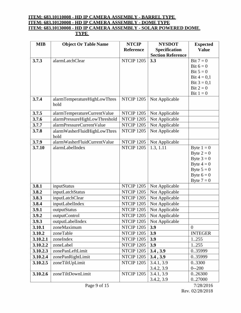
ITEM: 683.10110008 - HD IP CAMERA ASSEMBLY - BARREL TYPE ITEM: 683.10120008 - HD IP CAMERA ASSEMBLY - DOME TYPE ITEM: 683.10130008 - HD IP CAMERA ASSEMBLY - SOLAR POWERED DOME
TYPE
Page 9 of 15 7/28/2016 Rev. 02/28/2018
MIB Object Or Table Name NTCIP Reference
NYSDOT Specification
Section Reference
Expected Value
3.7.3 alarmLatchClear NTCIP 1205 3.3 Bit 7 = 0Bit 6 = 0 Bit 5 = 0 Bit 4 = 0,1 Bit 3 = 0,1 Bit 2 = 0 Bit 1 = 0
3.7.4 alarmTemperatureHighLowThreshold
NTCIP 1205 Not Applicable
3.7.5 alarmTemperatureCurrentValue NTCIP 1205 Not Applicable
3.7.6 alarmPressureHighLowThreshold NTCIP 1205 Not Applicable
3.7.7 alarmPressureCurrentValue NTCIP 1205 Not Applicable
3.7.8 alarmWasherFluidHighLowThres hold
NTCIP 1205 Not Applicable
3.7.9 alarmWasherFluidCurrentValue NTCIP 1205 Not Applicable
3.7.10 alarmLabelIndex NTCIP 1205 1.3, 1.11 Byte 1 = 0Byte 2 = 0 Byte 3 = 0 Byte 4 = 0 Byte 5 = 0 Byte 6 = 0 Byte 7 = 0
3.8.1 inputStatus NTCIP 1205 Not Applicable
3.8.2 inputLatchStatus NTCIP 1205 Not Applicable
3.8.3 inputLatchClear NTCIP 1205 Not Applicable
3.8.4 inputLabelIndex NTCIP 1205 Not Applicable
3.9.1 outputStatus NTCIP 1205 Not Applicable
3.9.2 outputControl NTCIP 1205 Not Applicable
3.9.3 outputLabelIndex NTCIP 1205 Not Applicable
3.10.1 zoneMaximum NTCIP 1205 3.9 0 3.10.2 zoneTable NTCIP 1205 3.9 INTEGER3.10.2.1 zoneIndex NTCIP 1205 3.9 1..2553.10.2.2 zoneLabel NTCIP 1205 3.9 1..2553.10.2.3 zonePanLeftLimit NTCIP 1205 3.4 , 3.9 0..359993.10.2.4 zonePanRightLimit NTCIP 1205 3.4 , 3.9 0..359993.10.2.5 zoneTiltUpLimit NTCIP 1205 3.4.1, 3.9
3.4.2, 3.9 0..3300 0--200
3.10.2.6 zoneTiltDownLimit NTCIP 1205 3.4.1, 3.93.4.2, 3.9
0..263000..27000

ITEM: 683.10110008 - HD IP CAMERA ASSEMBLY - BARREL TYPE ITEM: 683.10120008 - HD IP CAMERA ASSEMBLY - DOME TYPE ITEM: 683.10130008 - HD IP CAMERA ASSEMBLY - SOLAR POWERED DOME
TYPE
Page 10 of 15 7/28/2016 Rev. 02/28/2018
Motion Control Conformance Group MIB Object Or Table Name NTCIP
Reference NYSDOT
Specification Section Reference
Expected Value
3.10.1 zoneMaximum NTCIP 1205 Not Applicable
3.4.1 presetGotoPosition NTCIP 1205 3.2 0..n3.4.2 presetStorePosition NTCIP 1205 3.2 0..n3.5.1 positionPan NTCIP 1205 3.4 4 Byte msg3.5.2 positionTilt NTCIP 1205 3.4 4 Byte msg 3.5.3 positionZoomLens NTCIP 1205 3.4 4 Byte msg3.5.4 positionFocusLens NTCIP 1205 3.4 4 Byte msg3.5.5 positionIrisLens NTCIP 1205 3.4 4 Byte msg –
Only support continuous iris movement
n = number of presets supported by the CCTV Camera Assembly
Field HD IP Camera Assembly Requirements:
Provisions shall be made in the HD IP Camera Assembly for the installation of all accessories, cables, connectors, mounting hardware and equipment which are required for the full operation of the CCTV camera. The following equipment cabling shall be provided under other contract items:
a. Surge Protectors: All outputs/inputs cables from the camera including Ethernet cable, power cable and video and data shall be protected by individual surge protector. The surge protectors shall be the same or equal as: Emerson Edco-Cat6-PoE Emerson Edco-CX06-MI Emerson Edco-PC642 Emerson Edco-PHC
b. Power Injector or 24 VAC Power Supply: The contractor shall furnish and install the Power Injector or power supply unit as per the Regional TMC. The Power Injector or power supply shall comply with camera manufacture requirements and shall be a ruggedized unit.
c. Video Monitoring and PTZ control Software: The contractor shall furnish and install the video monitoring and control software as per camera manufacture recommendations and the Regional TMC integration requirement guidelines. The Contractor shall furnish and install all necessary licenses for full software operation and testing. All software shall be the latest version from the vendor with expiration date beyond the project closeout date.
d. Camera Cabling: The Contractor shall furnish all Input/Out puts cables from the HD IP camera to the field equipment cabinet. These cables shall include, Ethernet, Power, Grounding, Video, Data, Control and I/O signal. The Cables shall be outdoor rated applicable for vertical

ITEM: 683.10110008 - HD IP CAMERA ASSEMBLY - BARREL TYPE ITEM: 683.10120008 - HD IP CAMERA ASSEMBLY - DOME TYPE ITEM: 683.10130008 - HD IP CAMERA ASSEMBLY - SOLAR POWERED DOME
TYPE
Page 11 of 15 7/28/2016 Rev. 02/28/2018
installation. The Contractor’s cabling submittal shall include the camera cables with Camera Pole Lowering device connectors, if such lowering device is applicable to the project
e. Camera equipment and cables labels: The Contractor shall submit the complete label information of all HD IP Camera equipment and cables labels. The Labeling shall comply with the Regional Transportation Management Center (TMC) labeling format and standard requirements. All label materials shall be industry rated with minimum 10 year life time. The contractor can request a copy of the Regional TMC labeling format and standard.
f. Camera Alarm Interface/ Contacts – The Camera Alarm signal shall be connected to the Field Equipment cabinet. The Contractor shall furnish terminal and relays for connection to the cabinet Non-IP Alarm monitoring Unit. The Non-IP Alam Monitoring Unit will be paid under separate pay item.
g. Workmanship - Workmanship shall conform to the requirements of this specification and be in accordance with the highest industry standards.
h. All incidental parts necessary to complete the installation but not specified herein or on the plans shall be provided as necessary to provide a complete and properly operating system.
i. Manufacturer’s extended warranty: The contractor shall transfer the HD IP Camera manufacture warranty service for a period of thirty six (36) months from the delivery date of the system under normal use and service.
The Contractor shall submit a detailed dimensional drawing and the HD IP Camera equipment general layout of each type of components used in the camera assembly with data sheet or cut sheet submittal for review by the Regional TMC Engineer. Only HD IP Camera Assembly items with approve.
Layouts will be accepted under this Contract. After HD IP Camera equipment general layout and components approval contractor shall submit the detail schematic drawing for review by the regional TMC engineer. CONSTRUCTION DETAILS:
The HD IP Camera Assembly shall be installed on a designated CCTV pole or structure as shown on the plans along with conduit fittings necessary to bring cables from the camera to the designated field equipment cabinet. Each HD IP Camera Assembly shall be installed such that the line of sight of the camera is in the center line of the desired field of view when the camera is in the midpoint of the desired motion between the limit stops.
Each HD IP Camera Assembly shall be installed such that the home position for each camera shall be set to true North. The Regional TMC Engineer will provide the field of view of each camera, the limit settings of its vertical and horizontal movements and the programmable parameters prior to installation. The Contractor shall furnish and install the mounting hardware, including brackets, mounting plates, bolts, connectors, cabling between the camera housing and equipment cabinet, and weather heads required for the installation of the HD IP Camera Assembly. The Contractor shall install and connect the camera cables between the HD IP Camera Assembly and the

ITEM: 683.10110008 - HD IP CAMERA ASSEMBLY - BARREL TYPE ITEM: 683.10120008 - HD IP CAMERA ASSEMBLY - DOME TYPE ITEM: 683.10130008 - HD IP CAMERA ASSEMBLY - SOLAR POWERED DOME
TYPE
Page 12 of 15 7/28/2016 Rev. 02/28/2018
equipment cabinet in accordance with the manufacturer’s recommendations.
The Contractor shall program and configure the HD IP Camera with a minimum of two digital view streams. The Video streams shall have maximum and minimum transmission bandwidths. The High quality video shall be designated to the Regional TMC and low quality video for other applications. As per Regional TMC direction the Contractor shall program the Camera presets and the camera display labels. The contractor shall coordinate with the Regional TMC regarding the video quality and maximum and minimum bandwidth requirement. The contractor shall document all configuration and programming of the camera and the document shall be submitted to the Regional TMC.
HD IP Camera Assembly Final Test:
Each HD IP Camera Assembly shall be field inspected and tested by the Regional TMC Engineer. The Contractor shall provide the HD IP Camera Assembly testing plan and check list with following items:
1. HD IP Camera unit (Model, manufacture, MAC Address, Serial NO.) 2. Camera Mounting 3. Camera assembly on the Lowering Device (If Lowering device is used) 4. Camera Cables connection at the Field equipment Cabinet Check 5. Camera Cables Labels and Installation Check 6. Camera Surge Protector installation and function test (Test as per manufacture
recommendation) 7. Camera Cables Test 8. Camera Connection to Power and Network 9. Camera Setting and Configuration Test:
a- IP Addressing (IP addresses, Ports, VLAN, Multicasting) b- High Quality Video Stream (Visual test, Video Latency, Bandwidth, Frame Rate, S/N,
Error Rate, Zoom(1-30), Focus (Manual-Auto), and image stabilization Checks) c- Low resolution Video Stream (Visual test, Video Latency, Bandwidth, Frame Rate, S/N,
Error Rate, Zoom(1-30), Focus (Manual-Auto), and image stabilization Checks) d- PTZ Control Test via Ethernet Port (Pan (1-Max), Tele (1-Max), Movement Latency
(less than 1.5 Sec for 360 degree Checks) e- PTZ Control Test via Serial Data Port- If applicable (Pan (1-Max), Tele (1-Max),
Movement Latency (less than 1.5 Sec for 360 degree Checks) f- NTCIP Protocol PTZ Control Test g- Video Related Protocol Test h- Data Protocol Test i- Analog Video Quality Check- If applicable j- Home Parking Preset Test k- Presets Programming and Test (minimum 8 Presets Check) l- Tours Programming and Test (minimum 8 Tours Check)
10. Camera Control/Monitor Software Test (Software to be installed in NYSDOT Notebook) 11. Camera Power source Check 12. Camera Power Injector or Supply Voltage measurement

ITEM: 683.10110008 - HD IP CAMERA ASSEMBLY - BARREL TYPE ITEM: 683.10120008 - HD IP CAMERA ASSEMBLY - DOME TYPE ITEM: 683.10130008 - HD IP CAMERA ASSEMBLY - SOLAR POWERED DOME
TYPE
Page 13 of 15 7/28/2016 Rev. 02/28/2018
13. Camera Ground resistant measurement Check (Test may performed during the installation and the data has been documented)
14. HD IP Camera Equipment at the Field Cabinet Grounding check 15. HD IP Camera Equipment at the Field Cabinet mounting (safety and secure installation) check 16. Camera Equipment Labeling (format and material) 17. Camera cables and wiring Labeling (format and material) 18. HD IP Camera Assembly Layout Drawing Check 19. HD IP Camera Assembly Internal Wiring Diagram Drawing Check 20. Camera Equipment and Cables Check list
The contractor shall prepare the above test procedures and check lists and submit to the Engineer for review a minimum of 60-Days prior to test schedules.
All Operation, monitoring and control tests shall be completed in a local mode (Stand-Alone Test Action at each field location with no network connectivity), Remote mode (remote access to the site via network with HD IP camera software) and Central mode test (Test via the Regional TMC existing video management system). The Integration of the HD IP Camera to the existing the Regional TMC video management system will be performs by the Regional TMC. The contractor shall coordinate this integration with the Regional TMC.
Documentation:
Two submittals of the HD IP Camera Assembly Drawing Package shall be sent to the Regional TMC for review and approval. These submittals are:
HD IP Camera Assembly Submittal, the Contractor shall make this submittal in advance prior to camera integration and wiring and equipment assembly. The camera assembly drawings package shall include but not limited to:
HD IP Camera Assembly equipment Manufacture Cut Sheets HD IP Camera Assembly Layout (all physical dimensions and assembly details
shall be included) Camera Mounting details (including Lowering device mounting details and all
mounting hardware details) HD IP Camera Assembly Equipment at the Field Equipment Cabinet Placement HD IP Camera Assembly Power, Communication/Network and Control Diagrams
(all AC power, assign CB and power wires shall be included) HD IP Camera Assembly Communication/Network, control wiring Diagram (all
equipment connections and interfaces shall be included) HD IP Camera Assembly equipment, cables and wiring labeling details
Final HD IP Camera Assembly Drawing Package, The HD IP Camera Assembly Drawing Package shall be approved by the regional TMC prior to final acceptance of HD IP Camera Assembly. The HD IP Camera Assembly drawings package shall include but not limited to:
HD IP Camera Assembly, pole, pull boxes and cables Location Layouts. This Record Drawings shall include location of Pole, cabinet, camera and its equipment and wiring as per construction.

ITEM: 683.10110008 - HD IP CAMERA ASSEMBLY - BARREL TYPE ITEM: 683.10120008 - HD IP CAMERA ASSEMBLY - DOME TYPE ITEM: 683.10130008 - HD IP CAMERA ASSEMBLY - SOLAR POWERED DOME
TYPE
Page 14 of 15 7/28/2016 Rev. 02/28/2018
HD IP Camera Equipment Layouts(all physical dimensions and assembly details shall be included)
HD IP Camera Manufacturer’s Data: Submit manufacturer’s data sheets indicating camera systems and components proposed for use, including instruction manuals.
Camera mounting details (including foundation, cabinet base details and pole mounting details). The shop drawing shall include the details of mounting, physical mounting hardware details, connectors and all terminations of the wires.
HD IP Camera Equipment in Field Cabinet Placement (locations for the camera equipment components)
HD IP Camera Assembly Power and Communication/Network and control wiring Diagram (all equipment connections and interfaces shall be included). The contractor submittal shall have complete shop drawings including connection diagrams for interfacing equipment, list of connected equipment.
HD IP Camera Assembly Test Plan and Test Results (Submit results of field testing of every device including date, testing personnel, retesting date if applicable, and confirmation that every device passed field testing.)
HD IP Camera Assembly equipment, cables and wiring labeling details
Operation and Maintenance Data: Submit manufacturer’s operation and maintenance data, customized to the system installed. Include system and operator manuals.
Complete list of replaceable parts including names of vendors for parts not identified by universal part numbers such as JEDEC, RETMA or EIA
All HD IP Camera Assembly drawing shall be 11 x 17 size. All drawing shall be submitted in hard copy and electronic, and CAD (Microstation) formats. The Final HD IP Camera Assembly Drawing Package shall be signed by the contractor. Each HD IP Camera Assembly shall be supplied with three (3) copies of the Final HD IP Camera Assembly Drawing Package. One (1) copy shall be placed in a clear plastic envelope and left in the CCTV Field cabinet. Two (2) copies shall be delivered to the Engineer and the regional TMC. The Electronic/CAD (Microstation) copies shall be submitted to the regional TMC. METHOD OF MEASUREMENT:
Each HD IP Camera Assembly will be measured as the number of complete units furnished, installed and tested.
BASIS OF PAYMENT:
The unit price bid for each HD IP Camera Assembly shall include the cost of furnishing all labor, materials, tools, pedestal, equipment and incidentals as necessary to complete the work.

ITEM: 683.10110008 - HD IP CAMERA ASSEMBLY - BARREL TYPE ITEM: 683.10120008 - HD IP CAMERA ASSEMBLY - DOME TYPE ITEM: 683.10130008 - HD IP CAMERA ASSEMBLY - SOLAR POWERED DOME
TYPE
Page 15 of 15 7/28/2016 Rev. 02/28/2018
Progress payments will be made as follows:
Twenty Five percent (25%) of the bid price of each item will be paid upon satisfactory completion and approval of the HD IP Camera Assembly Submittal.
Sixty percent (60%) will be paid upon satisfactory completion of the HD IP Camera Assembly Test.
Fifteen percent (15%) will be paid upon satisfactory completion of 90-Day Operational Test of the HD IP Camera Assembly.

ITEM 683.10250208 BLUETOOTH TRAVEL TIME RECEIVERS (SOLAR POWERED
WITH BATTERY / CELLULAR MODEM)
Page 1 of 7 2/9/2017
Rev. 7/14/2017
DESCRIPTION
This work shall consist of furnishing and installing Bluetooth receivers and associated hardware,
capable of measuring vehicle flows by measuring Bluetooth MAC (Media Access Control)
addresses. The system will be used to measure and collect high quality travel times, in real-time,
from the traffic stream by matching MAC addresses at two or more locations.
The Bluetooth receivers and associated hardware shall be installed in accordance with the Plans
or as directed by the Engineer in accordance with the contract documents. A full set of
documentation is required with the system.
All materials furnished, assembled, fabricated or installed shall be new, corrosion resistant and in
strict accordance with the details shown in the plans and in the Special Notes. All equipment
furnished under this item shall be current production equipment, identical models of which are
field operational.
The Bluetooth receiver working in conjunction with a back end support data processing system
must deliver real-time speed and travel time information of the road(s) where the receivers are
deployed.
MATERIALS
Bluetooth travel time receiver
The Bluetooth Travel Time Receivers and associated equipment shall include all
mounting hardware as recommended by the manufacturer and as approved by the
Engineer.
The Bluetooth Travel Time Receivers and processing system shall be compatible and
from the same manufacturer.
Each Bluetooth Travel Time Receiver shall be capable of providing vehicle detection
zone coverage for a minimum radius of 165 feet.
The receiver shall be complient with all FCC regulations.
The data uploaded by the Bluetooth Travel Time Receivers shall be hosted by a dedicated
server supplied by the Bluetooth receiver manufacturer; the data shall be accessed and
retrieved by the Department. The manufacturer of the Bluetooth Travel Time Receiver
will supply the Department with the following:
o Map based real-time speed and travel time information displayed on a website
hosted by the Bluetooth receiver vendor.
o Statistical data reports covering speed, travel time, MAC pairs, origin and
destination.
o Data archiving
o Service level support
The operating system shall operate at temperatures from 40 degrees F to +160 degrees F.

ITEM 683.10250208 BLUETOOTH TRAVEL TIME RECEIVERS (SOLAR POWERED
WITH BATTERY / CELLULAR MODEM)
Page 2 of 7 2/9/2017
Rev. 7/14/2017
The Bluetooth Travel Time Receiver shall be able to communicate via 4G LTE modem
or TCP/IP network.
The device shall have one or more Omni directional antenna, for a minimum combined 4
dBi antenna strength for Bluetooth detection.. Bluetooth receivers supporting 4G LTE
communications the device shall have a single MIMO compatible antenna.. For GPS the
device shall have a single compatible antenna, as recommended by the Manufacture.
The Bluetooth receiver and all required accessories shall be contained within a cabinet.
The cabinet shall be a NEMA 4X enclosure. The cabinet shall be able to be pole
mounted.
The enclosure shall be no larger than 12” x 10” x 8”.
The receiver shall contain data storage capabilities and be able to store data for up to a
year.
Qualifications
Prior to commencing work on this item, the Contractor shall provide the Engineer with
evidence of the Bluetooth Travel Time Receivers manufacturer having provided at least
three successful detector installations of six or more sensors identical to the model
proposed on limited access facilities or, as judged by the Engineer, installation experience
of comparable complexity. The submittal shall include the names and phone numbers of
users familiar with the installations. The data processing, storage, and operations &
maintenance contract for Bluetooth receivers installed shall be fully compatible with any
existing system in operation, or as specified by the contract documents or Engineer.
Mounting Bluetooth Travel Time Receivers:
o The receiver unit shall be mounted along the shoulder of the roadway on a pole,
or sign structure.
o The receiver antenna shall meet the specified performance criteria with a
mounting height in the range of 10 to 16 feet above the roadway. The height will
be as recommended by the operations manual as suggested by the manufacturer.
o The Horizontal distance from the receiver antenna to the farthest detection zone
shall be 325 feet or as specified in the contract documents.
Data processing and storage:
The vendor shall have available, and provide a complete backend support system, developed
to process the data collected by the Bluetooth receiver. Such support shall also include a
secure web-based user interface to enable the contractor to view, analyze and configure data
outputs.
Data processing will include travel time, flow, speed, and MAC address counts. The data
shall be available for viewing in real time or as post processed
The data processing shall also filter the following as needed to deliver the most accurate
information:
o Pedestrian

ITEM 683.10250208 BLUETOOTH TRAVEL TIME RECEIVERS (SOLAR POWERED
WITH BATTERY / CELLULAR MODEM)
Page 3 of 7 2/9/2017
Rev. 7/14/2017
o Vehicular
o Mean, Median, etc.
Data uploaded from the Bluetooth device will be hosted and stored by the Client on a
dedicated, locally hosted, server within the Regional Transportation Management Center
(TMC).
o Power - Redundant power is available within the TMC. It is designed with battery
backup for uninterrupted power supply (UPS), supported by a Diesel generator to
ensure uninterruptible power.
This data can be via a Bluetooth web server. The raw data can also be retrieved from the
hosted database server by specific search options. The raw and processed data needs to
interface with non-Vendor systems therefore the Bluetooth system is to have an Application
Programming Interface (API) with predefined methods for accessing datasets from the
database server.. This task would be scoped and statement of work would be agreed upon by
all parties, with a separate agreement.
Operations and maintenance:
The following shall be included as a complete turnkey operations and maintenance
package for the end user:
o Web-based Map with device location and information
o Real-time chart displaying origin, destination, time stamp, travel-time & speed
o 5 years data storage, which also needs to be user expandable/scalable
o Historical reports showing matched pairs, travel times and speeds
o Web-based GUI for Operations and Maintenance
o Software Bug Fixes
o Software Performance Improvements
o Firmware Updates
o XML based API, via REST, SOAP & JSON
o 24 x 7 Monitoring for each device
o Email/Text Alerting
o 48 Hour Depot return on Hardware
Software Diagnostics:
The Bluetooth receiver shall contain advanced features designed to allow the unit to operate
efficiently in a remote environment. Diagnostic heartbeat information such as voltage and
temperature monitoring as well as software stability information should be periodically sent
along with the MAC addresses such that the health of the receiver is known. The system is to
be designed to be able to automatically reboot if a condition is detected that requires such
action. In the event a system recovery is required, the receiver is to be designed to
automatically re-image the system memory.

ITEM 683.10250208 BLUETOOTH TRAVEL TIME RECEIVERS (SOLAR POWERED
WITH BATTERY / CELLULAR MODEM)
Page 4 of 7 2/9/2017
Rev. 7/14/2017
In addition, the receiver should have the ability to download software patches and upgrades
over the air without the need to physically visit the unit.
Communications:
Ethernet network communication
o An Ethernet port shall be integrated within the interface unit. The Ethernet port shall
conform to 802.3 Ethernet specifications and shall auto-sense between 10 and 100
Mbps data rates.
o Industry standard TCP/IP protocol shall be supported. The Ethernet connection shall
be made through an RJ-45 connector.
4G LTE modem communication
o The 4G modem shall be capable of transmitting data from the Bluetooth device to the
Traffic Management Centre. . Traffic may need to be routed via an Access Point
Name (APN) provided through a cellular provider should the detailed design or
regional TMC require it to.
o The modem shall be capable of transmitting at upload and download rates required
for the Bluetooth unit as recommended by the Manufacture, with a very low power
standby mode to conserve the battery.
o A 4G LTE modem shall be backwards compatible with 3G and 2G cellular
frequencies. The modem shall be capable of communicating via supported frequency
bands and State approved carriers.
• Supported Frequency Bands:
LTE: 1900(B2), AWS(B4), 850(B5), 700(B13), 700(B17), 1900(B25)
WCDMA: 2100(B1), 1900(B2), AWS(B4), 850(B5), 900(B8)
EV-DO/CDMA: 800(BC0), 1900(BC1), 1700(BC10)
GSM/GPRS/EDGE: Quad-band
• Carrier Approvals: Verizon, AT&T, Sprint, T-Mobile USA
The Contractor is to request the 4G LTE SIM cards and the configuration of the modem from the
regional TMC, this shall take place prior to any installation works carried out by the contractor.
The coordination of the works shall be via the NYSDOT Engineer.
Power:
Power over Ethernet (PoE)
IEEE 802.3af standard
PoE Voltage - 48VDC
110/230 VAC supply to the injector
DC Power
o Current
• Typical - 150mA @ 12V

ITEM 683.10250208 BLUETOOTH TRAVEL TIME RECEIVERS (SOLAR POWERED
WITH BATTERY / CELLULAR MODEM)
Page 5 of 7 2/9/2017
Rev. 7/14/2017
• Max - 250mA @ 12V
o Voltage
• Min - 9.5VDC
• Max - 50VDC
AC Power
o 100/230VAC 50Hz to 60Hz
Surge protectors shall be in accordance with the recommendations of the manufacturer of the
Bluetooth supplier. If the manufacturer has no recommendation, then provide a surge
protector with the following features:
o Category 5 compliant.
o Compatible with high power POE circuits.
o Shielded RJ-45 jacks and metal housing.
o Three stage protection incorporating a differential gas discharge tube, current limiting
resistors (data path) or inductors (power path), and clamping diodes.
o Ground lug on the housing.
o The surge protection shall operate at temperatures of -40°F to +176°F.
o Clamping voltage of 58 volts.
Connectors and harness:
Provide Category 5e or Category 6 cable that is recommended for outdoor use.
The cable shall be shielded or screened. It shall be flooded with a water-blocking,
semidry, thixotropic material that is easily removed with citrus-based cleaners. The
cable’s jacket shall be black and UV protected.
The shield shall be corrugated aluminum.
The cable shall operate at temperatures from -40°F to +140°F.
The Contractor shall provide all cables and mating connectors including power cables in
conformance with the NEC and all other applicable codes including local codes.
CONSTRUCTION DETAILS
The Contractor shall furnish and install Bluetooth Travel Time Receivers as specified in
the Contract Documents.
The Contractor shall furnish and install all cabling, risers, conduit, weatherheads, and
surge protection, in accordance with the manufacturer recommendations, and not
otherwise shown on contract documents, to provide a complete operational installation,
with no additional payment being made.

ITEM 683.10250208 BLUETOOTH TRAVEL TIME RECEIVERS (SOLAR POWERED
WITH BATTERY / CELLULAR MODEM)
Page 6 of 7 2/9/2017
Rev. 7/14/2017
The receiver enclosure shall be electrically grounded using a No. 6 AWG bonding
conductor.
The Bluetooth Travel Time Receivers shall be installed at the locations shown on the
plans and as directed by the Engineer. Detector poles shall be paid for separately.
Cabinets shall be connected to power with a fused switch, or similar, provided within the
cabinet unless otherwise directed by the contract documents or the engineer. Units shall
be connected to power according to manufacturer instructions, unless otherwise directed
by the contract or the engineer.
Configuration programming and backup
o The Contractor shall use manufacturer supplied configuration software to perform
detection zone fine tuning at each receiver location.
o The Contractor shall also supply to the Engineer three copies of the software with
full documentation for use by future maintenance personnel.
Training
Installer training
o All of the personnel involved in the installation and testing of this equipment shall
have received training in such task prior to installation of the equipment.
o Proof of training shall be submitted a minimum of ten-working days prior to the
start of the first installation.
o The Contractor shall not install the Bluetooth Travel Time Receiver equipment
until the personnel have been approved by the Engineer.
Maintenance and Operations Training:
o All of the personnel involved in the maintenance, operations and repair of this
equipment shall have received training in such task prior to acceptance of the
equipment.
o Training shall consist of formal classroom lectures as well as “hands-on”
opportunity to install and configure a Bluetooth Travel Time Receiver in the field.
o Proof of training shall be submitted and approved by the Engineer prior to final
acceptance.
Documentation:
Manuals
o The Contractor shall furnish ten (10) sets of maintenance and operations manuals.
o The maintenance manuals shall contain maintenance and troubleshooting charts
and procedures to permit fault isolation to the lowest replaceable unit level.
o The Contractor shall assemble the individual manuals and trouble shooting and
fault isolation procedures into loose leaf binder(s).
o The equipment manuals shall as a minimum contain the following:

ITEM 683.10250208 BLUETOOTH TRAVEL TIME RECEIVERS (SOLAR POWERED
WITH BATTERY / CELLULAR MODEM)
Page 7 of 7 2/9/2017
Rev. 7/14/2017
Complete and accurate schematic diagrams
Complete installation and operation procedures
Complete performance specifications (functional, electrical, mechanical
and environmental) of the unit.
Complete list of replaceable parts including names of vendors for parts not
identified by universal part numbers such as JEDEC/ RETMA or EIA.
Complete maintenance and troubleshooting procedures.
Warranties and guarantees
o The Contractor shall provide warranties and guarantees for the equipment’s
operations for a period of 12 months starting from the passing of the Final System
Acceptance Tests, covering both parts and labor for the detector, all associated
interface cards and cables, and all accessory equipment.
METHOD OF MEASUREMENT
Bluetooth Travel Time Receiver will be measured for payment as the number of Bluetooth
receivers furnished, installed, tested, and made fully operational.
BASIS OF PAYMENT
The unit price bid for each Bluetooth Travel Time Receiver shall include the cost of furnishing
all labor, training, materials, tools and equipment necessary to complete the work. The cost of all
miscellaneous hardware, junction boxes, cabling and connectors, mounting hardware, training,
documentation, and testing, including a three year Operations & Maintenance contract with a
three year duration from the Bluetooth receiver vendor shall be included in the unit price bid for
this item.
Progress payments will be made as follows:
50% upon the bid price of each item will be paid upon satisfactory completion of
Milestone 3, On-Site Stand Alone Tests
20% upon will be paid upon satisfactory completion of Milestone 4, System Interface
Test
20% upon will be paid upon satisfactory completion of Milestone 5, System Performance
Tests
10% upon will be paid upon satisfactory completion of Milestone 6, 90-Day Operational
Test, as described in the ITS Special Provisions part of the contract and within the
plans/proposal.

ITEM 683.10250308 - BLUETOOTH TRAVEL TIME RECEIVERS (AC POWERED WITH COMMUNICATIONS)
Page 1 of 7 02/09/2017 Rev. 07/14/2017
DESCRIPTION
This work shall consist of furnishing and installing Bluetooth receivers and associated hardware, capable of measuring vehicle flows by measuring Bluetooth MAC (Media Access Control) addresses. The system will be used to measure and collect high quality travel times, in real-time, from the traffic stream by matching MAC addresses at two or more locations. The Bluetooth receivers and associated hardware shall be installed in accordance with the Plans or as directed by the Engineer in accordance with the contract documents. A full set of documentation is required with the system. All materials furnished, assembled, fabricated or installed shall be new, corrosion resistant and in strict accordance with the details shown in the plans and in the Special Notes. All equipment furnished under this item shall be current production equipment, identical models of which are field operational. The Bluetooth receiver working in conjunction with a back end support data processing system must deliver real-time speed and travel time information of the road(s) where the receivers are deployed.
MATERIALS
Bluetooth travel time receiver
The Bluetooth Travel Time Receivers and associated equipment shall include all mounting hardware as recommended by the manufacturer and as approved by the Engineer.
The Bluetooth Travel Time Receivers and processing system shall be compatible and from the same manufacturer.
Each Bluetooth Travel Time Receiver shall be capable of providing vehicle detection zone coverage for a minimum radius of 165 feet.
The receiver shall be compliant with all FCC regulations. The data uploaded by the Bluetooth Travel Time Receivers shall be hosted by a dedicated
server supplied by the Bluetooth receiver manufacturer; the data shall be accessed and retrieved by the Department. The manufacturer of the Bluetooth Travel Time Receiver will supply the Department with the following:
o Map based real-time speed and travel time information displayed on a website hosted by the Bluetooth receiver vendor.
o Statistical data reports covering speed, travel time, MAC pairs, origin and destination.
o Data archiving o Service level support
The operating system shall operate at temperatures from - 40 F to +160 F. The Bluetooth Travel Time Receiver shall be able to communicate via 4G LTE modem
or TCP/IP network. The device shall have one or more Omni directional antenna, for a minimum combined 4
dBi antenna strength for Bluetooth detection.. Bluetooth receivers supporting 4G LTE

ITEM 683.10250308 - BLUETOOTH TRAVEL TIME RECEIVERS (AC POWERED WITH COMMUNICATIONS)
Page 2 of 7 02/09/2017 Rev. 07/14/2017
communications the device shall have a single multiple input-multiple output (MIMO) compatible antenna.. For GPS the device shall have a single compatible antenna, as recommended by the Manufacture.
The Bluetooth receiver and all required accessories shall be contained within a cabinet. The cabinet shall be a NEMA 4X enclosure. The cabinet shall be able to be pole mounted.
The enclosure shall be no larger than 12” x 10” x 8”. The receiver shall contain data storage capabilities and be able to store data for up to a
year. VPN- if necessary 1 Ethernet Port as a minimum Remote login need?
Qualifications
Prior to commencing work on this item, the Contractor shall provide the Engineer with evidence of the Bluetooth Travel Time Receivers manufacturer having provided at least three successful detector installations of six or more sensors identical to the model proposed on limited access facilities or, as judged by the Engineer, installation experience of comparable complexity. The submittal shall include the names and phone numbers of users familiar with the installations. The data processing, storage, and operations & maintenance contract for Bluetooth receivers installed shall be fully compatible with any existing system in operation, or as specified by the contract documents or Engineer.
Mounting Bluetooth Travel Time Receivers: o The receiver unit shall be mounted along the shoulder of the roadway on a pole,
or sign structure. o The receiver antenna shall meet the specified performance criteria with a
mounting height in the range of 10 to 16 feet above the roadway. The height will be as recommended by the operations manual as suggested by the manufacturer.
o The Horizontal distance from the receiver antenna to the farthest detection zone shall be 325 feet or as specified in the contract documents.
Data processing and storage:
The vendor shall have available, and provide a complete backend support system, developed to process the data collected by the Bluetooth receiver. Such support shall also include a secure web-based user interface to enable the contractor to view, analyze and configure data outputs.
Data processing will include travel time, flow, speed, and MAC address counts. The data shall be available for viewing in real time or as post processed
The data processing shall also filter the following as needed to deliver the most accurate information:
o Pedestrian o Vehicular o Mean, Median, etc.

ITEM 683.10250308 - BLUETOOTH TRAVEL TIME RECEIVERS (AC POWERED WITH COMMUNICATIONS)
Page 3 of 7 02/09/2017 Rev. 07/14/2017
Data uploaded from the Bluetooth device will be hosted and stored by the Client on a dedicated, locally hosted, server within the Regional Transportation Management Center (TMC).
o Power - Redundant power is available within the TMC. It is designed with battery backup for uninterrupted power supply (UPS), supported by a Diesel generator to ensure uninterruptible power.
This data can be via a Bluetooth web server. The raw data can also be retrieved from the hosted database server by specific search options. The raw and processed data needs to interface with non-Vendor systems therefore the Bluetooth system is to have an Application Programming Interface (API) with predefined methods for accessing datasets from the database server.. This task would be scoped and statement of work would be agreed upon by all parties, with a separate agreement.
Operations and maintenance:
The following shall be included as a complete turnkey operations and maintenance package for the end user: o Web-based Map with device location and information o Real-time chart displaying origin, destination, time stamp, travel-time & speed o 5 years data storage, which also needs to be user expandable/scalable o Historical reports showing matched pairs, travel times and speeds o Web-based GUI for Operations and Maintenance o Software Bug Fixes o Software Performance Improvements o Firmware Updates o XML based API, via REST, SOAP & JSON o 24 x 7 Monitoring for each device o Email/Text Alerting o 48 Hour Depot return on Hardware
Software Diagnostics:
The Bluetooth receiver shall contain advanced features designed to allow the unit to operate efficiently in a remote environment. Diagnostic heartbeat information such as voltage and temperature monitoring as well as software stability information should be periodically sent along with the MAC addresses such that the health of the receiver is known. The system is to be designed to be able to automatically reboot if a condition is detected that requires such action. In the event a system recovery is required, the receiver is to be designed to automatically re-image the system memory.
In addition, the receiver should have the ability to download software patches and upgrades over the air without the need to physically visit the unit.
Communications:
Ethernet network communication o A singleEthernet port at a minimum shall be integrated within the interface unit. The
Ethernet port shall conform to 802.3 Ethernet specifications and shall auto-sense between 10 and 100 Mbps data rates.
o How many Ethernet ports?

ITEM 683.10250308 - BLUETOOTH TRAVEL TIME RECEIVERS (AC POWERED WITH COMMUNICATIONS)
Page 4 of 7 02/09/2017 Rev. 07/14/2017
o Industry standard TCP/IP protocol shall be supported. The Ethernet connection shall be made through an RJ-45 connector.
4G LTE modem communication o The 4G modem shall be capable of transmitting data from the Bluetooth device to the
Traffic Management Centre. . Traffic may need to be routed via an Access Point Name (APN) provided through a cellular provider should the detailed design or regional TMC require it to.
o The modem shall be capable of transmitting at upload and download rates required for the Bluetooth unit as recommended by the Manufacture, with a very low power standby mode to conserve the battery.
o A 4G LTE modem shall be backwards compatible with 3G and 2G cellular frequencies. The modem shall be capable of communicating via supported frequency bands and State approved carriers.
• Supported Frequency Bands: LTE: 1900(B2), AWS(B4), 850(B5), 700(B13), 700(B17), 1900(B25) WCDMA: 2100(B1), 1900(B2), AWS(B4), 850(B5), 900(B8) EV-DO/CDMA: 800(BC0), 1900(BC1), 1700(BC10) GSM/GPRS/EDGE: Quad-band
• Carrier Approvals: Verizon, AT&T, Sprint, T-Mobile USA
The Contractor is to request the 4G LTE SIM cards and the configuration of the modem from the regional TMC, this shall take place prior to any installation works carried out by the contractor. The coordination of the works shall be via the Engineer.
Power:
Power over Ethernet (PoE) IEEE 802.3af standard PoE Voltage - 48VDC 110/230 VAC supply to the injector
DC Power o Current
• Typical - 150mA @ 12V • Max - 250mA @ 12V
o Voltage • Min - 9.5VDC • Max - 50VDC
AC Power o 100/230VAC 50Hz to 60Hz
Surge protectors shall be in accordance with the recommendations of the manufacturer of the Bluetooth supplier. If the manufacturer has no recommendation, then provide a surge protector with the following features:
o Category 5 compliant. o Compatible with high power POE circuits. o Shielded RJ-45 jacks and metal housing.

ITEM 683.10250308 - BLUETOOTH TRAVEL TIME RECEIVERS (AC POWERED WITH COMMUNICATIONS)
Page 5 of 7 02/09/2017 Rev. 07/14/2017
o Three stage protection incorporating a differential gas discharge tube, current limiting resistors (data path) or inductors (power path), and clamping diodes.
o Ground lug on the housing. o The surge protection shall operate at temperatures of -40°F to +176°F. o Clamping voltage of 58 volts.
Connectors and harness:
Provide Category 5e or Category 6 cable that is recommended for outdoor use. The cable shall be shielded or screened. It shall be flooded with a water-blocking,
semidry, thixotropic material that is easily removed with citrus-based cleaners. The cable’s jacket shall be black and UV protected.
The shield shall be corrugated aluminum. The cable shall operate at temperatures from -40°F to +140°F. The Contractor shall provide all cables and mating connectors including power cables in
conformance with the NEC and all other applicable codes including local codes. CONSTRUCTION DETAILS
The Contractor shall furnish and install Bluetooth Travel Time Receivers as specified in the Contract Documents.
The Contractor shall furnish and install all cabling, risers, conduit, weatherheads, and surge protection, in accordance with the manufacturer recommendations, and not otherwise shown on contract documents, to provide a complete operational installation, with no additional payment being made.
The receiver enclosure shall be electrically grounded using a No. 6 AWG bonding conductor.
The Bluetooth Travel Time Receivers shall be installed at the locations shown on the plans and as directed by the Engineer. Detector poles shall be paid for separately.
Cabinets shall be connected to power with a fused switch, or similar, provided within the cabinet unless otherwise directed by the contract documents or the engineer. Units shall be connected to power according to manufacturer instructions, unless otherwise directed by the contract or the engineer.
Configuration programming and backup o The Contractor shall use manufacturer supplied configuration software to perform
detection zone fine tuning at each receiver location. o The Contractor shall also supply to the Engineer three copies of the software with
full documentation for use by future maintenance personnel.
Training
Installer training o All of the personnel involved in the installation and testing of this equipment shall
have received training in such task prior to installation of the equipment. o Proof of training shall be submitted a minimum of ten-working days prior to the
start of the first installation. o The Contractor shall not install the Bluetooth Travel Time Receiver equipment
until the personnel have been approved by the Engineer.

ITEM 683.10250308 - BLUETOOTH TRAVEL TIME RECEIVERS (AC POWERED WITH COMMUNICATIONS)
Page 6 of 7 02/09/2017 Rev. 07/14/2017
Maintenance and Operations Training: o All of the personnel involved in the maintenance, operations and repair of this
equipment shall have received training in such task prior to acceptance of the equipment.
o Training shall consist of formal classroom lectures as well as “hands-on” opportunity to install and configure a Bluetooth Travel Time Receiver in the field.
o Proof of training shall be submitted and approved by the Engineer prior to final acceptance.
Documentation:
Manuals o The Contractor shall furnish ten (10) sets of maintenance and operations manuals. o The maintenance manuals shall contain maintenance and troubleshooting charts
and procedures to permit fault isolation to the lowest replaceable unit level. o The Contractor shall assemble the individual manuals and trouble shooting and
fault isolation procedures into loose leaf binder(s). o The equipment manuals shall as a minimum contain the following:
Complete and accurate schematic diagrams Complete installation and operation procedures Complete performance specifications (functional, electrical, mechanical
and environmental) of the unit. Complete list of replaceable parts including names of vendors for parts not
identified by universal part numbers such as JEDEC/ RETMA or EIA. Complete maintenance and troubleshooting procedures.
Warranties and guarantees o The Contractor shall provide warranties and guarantees for the equipment’s
operations for a period of 24 months starting from the passing of the Final System Acceptance Tests, covering both parts and labor for the detector, all associated interface cards and cables, and all accessory equipment.
METHOD OF MEASUREMENT
Bluetooth Travel Time Receiver will be measured for payment as the number of Bluetooth receivers furnished, installed, tested, and made fully operational. BASIS OF PAYMENT
The unit price bid for each Bluetooth Travel Time Receiver shall include the cost of furnishing all labor, training, materials, tools and equipment necessary to complete the work. The cost of all miscellaneous hardware, junction boxes, cabling and connectors, mounting hardware, training, documentation, and testing, including a three year Operations & Maintenance contract with a three year duration from the Bluetooth receiver vendor shall be included in the unit price bid for this item.
Progress payments will be made as follows:
50% upon the bid price of each item will be paid upon satisfactory completion of Milestone 3, On-Site Stand Alone Tests

ITEM 683.10250308 - BLUETOOTH TRAVEL TIME RECEIVERS (AC POWERED WITH COMMUNICATIONS)
Page 7 of 7 02/09/2017 Rev. 07/14/2017
20% upon will be paid upon satisfactory completion of Milestone 4, System Interface Test
20% upon will be paid upon satisfactory completion of Milestone 5, System Performance Tests
10% upon will be paid upon satisfactory completion of a six (6) month period of operation without any failure In the event of a failure of any Contractor supplied equipment, that portion of the system affected by the failure shall be subjected to an additional 30 day test period. The Engineer will make the determination as to which equipment is affected by the failure.

ITEM 683.91150108 – MULTI LANE RADAR TRAFFIC DETECTOR ITEM 683.91150208 – MULTI LANE RADAR TRAFFIC DETECTOR WITH
EMBEDED CAMERA ITEM 683.91150408 – SOLAR OPTION FOR MULTI-LANE RADAR TRAFFIC
DETECTOR
Page 1 of 11 03/02/2017 Rev. 01/19/2018
DESCRIPTION:
This work shall consist of furnishing and installing of Multi Lane Radar Traffic Detector, Multi Lane Radar Traffic Detector with Embedded Camera and the Solar Option for Multi-Lane Radar Traffic Detectors at the locations shown in the plans and as directed by the Engineer.
The sensor shall be a true presence type detector which can provide volume, lane occupancy, classification, and speed information on at least 12 discreet detection zones from a side-fire location. The detector information shall be available via an asynchronous serial communications line operated in a multi drop configuration. The collected information shall be made available to 3rd party systems and users whilst utilizing an open protocol.
If specified for installations not requiring a radar detector with embedded camera, the Solar Power option shall include solar power panels with battery back-up in accordance with the Plans or as directed by the Engineer. in accordance with the contract documents.
A set of documentation including solar power calculations, solar power system diagrams and component details, panel structure and mounting details and the battery backup enclosure details and schematic is required with each detector furnished. MATERIALS:
All materials furnished, assembled, fabricated, or installed shall be new, corrosion resistant, and in strict accordance with the standards set by the New York State Department of Transportation (NYSDOT). The material shall contain all the components described in the subsequent material specifications. All necessary incidental components, cables, software/ firmware, hardware, and mounting attachments shall be supplied to accomplish a fully operational multi-lane radar unit installation. All equipment and component parts furnished shall be of the latest design, and manufacture. All parts shall be of high quality workmanship, and no part or attachment shall be substituted or applied contrary to the manufacturer’s recommendations and standard practices.
The design life of all components, operating 24 hours per day, shall be ten (10) years minimum.
Radar Detector Requirements:
a. Radar Detector Unit
The detector shall be mountable from a side fire location and shall comply with the limits of a Class A digital device pursuant to Part 15 of the FCC rules
The unit shall not interfere with any known equipment
The unit shall support at least 12 detection zones which can effectively cover 12 lanes of traffic within the range of 10 feet to 250 feet from the sensor, when the sensor is mounted at least 17 feet higher than the roadway profile
The width and location of the detection zones shall be fully programmable via a PC or network interface, including Bluetooth interface.

ITEM 683.91150108 – MULTI LANE RADAR TRAFFIC DETECTOR ITEM 683.91150208 – MULTI LANE RADAR TRAFFIC DETECTOR WITH
EMBEDED CAMERA ITEM 683.91150408 – SOLAR OPTION FOR MULTI-LANE RADAR TRAFFIC
DETECTOR
Page 2 of 11 03/02/2017 Rev. 01/19/2018
The unit shall retain its programming in non-volatile memory
Basic resolution of the unit shall be 1.5msec or less
The reporting interval shall be user selectable within the range of 10 to 900 seconds in increments of ten seconds
Support TCP/IP protocol
Communication interface shall be Ethernet 10/100 Base T Auxiliary Communication interface shall be a RS-232/422 serial Data with a minimum operation rate of 9600 Bps.
The unit shall support both contention and polled protocols. In contention mode, the unit shall report volume, average occupancy, and average speed over the reporting interval at the end of the interval. In polled mode, a communication address shall be assigned to the unit via its setup program. Upon receiving a command from the center with the appropriate address the unit shall respond with the accumulated volume, average occupancy, and average speed in the period since the last poll request was issued.
Complete protocol descriptions shall be supplied with the submittal for the unit. These protocol descriptions shall be complete and adequate for the purpose of developing or supplying software to retrieve the information from the sensor, though an open protocol.
Comply with NTCIP standard. The compliance Test certification shall be provided. All necessary third part hardware and software for NTCIP compliance shall be furnished and installed.
Frequency: K band, 24 GHz
Contact Closure: 12 Output for Vehicle present and Speed
Unit Enclosure: Rugged NEMA 4X or IP 67 rated
Power: 12-24 VDC, Max 5 Watts, Multi Lane Radar Traffic Detector; or
Power: 12-24 VDC, Max 15 Watts, Multi Lane Radar Traffic Detector with Embedded Camera
Surge protection (power and data) shall comply with IEEE Standard 587-1980 Category C.
Operating Temperature: -40ºF to +165ºF
Operating Wind : Up to 120 Mph
Humidity: 5 to 95%, non-condensing

ITEM 683.91150108 – MULTI LANE RADAR TRAFFIC DETECTOR ITEM 683.91150208 – MULTI LANE RADAR TRAFFIC DETECTOR WITH
EMBEDED CAMERA ITEM 683.91150408 – SOLAR OPTION FOR MULTI-LANE RADAR TRAFFIC
DETECTOR
Page 3 of 11 03/02/2017 Rev. 01/19/2018
Weather: Rain or snow up to 4 inches per hour.
Vibration: 2 g up to 200 Hz sinusoidal.
Shock: of 5 g 10 millisecond half sine wave
Data Measurement Accuracy:
Volume Measurement - Maximum +/- 5% difference from actual count for a 5 min period
Occupancy - Maximum +/- 10% difference from actual measurement by a 6’ loop for a 5 min period
Speed - Maximum +/- 10% difference from actual speed or radar gun speed measurement for averaging in a 5 min period.
Classification - The unit shall be able to differentiate long from short vehicles as:
i. FHWA Classification Class 1-3,
ii. FHWA Classification Class 4
iii. FHWA Classification Class 5-7,
iv. FHWA Classification Class 8-10
v. FHWA Classification Class 1-13
Data measurement accuracy test shall be performed by the Regional TMC.
The Radar Unit design shall be inherently temperature compensated to prevent abnormal operation. The circuit design shall include such compensation as is necessary to overcome adverse effects due to temperature in the specified environmental range. The unit shall not require programming changes to compensate for different environmental conditions encountered from season to season.
b. Mounting Hardware
The radar detector shall be supplied with a mounting bracket. The mounting bracket shall be designed to allow the detector to be mounted on a pole type structure and shall utilize a ball-joint. The ball joint shall be equipped with a locking pin which will allow the detector to be mechanically aimed and secured in place. The ball joint will allow the unit to be tilted in both directions. The mounting bracket shall be supplied with stainless steel bands which will allow the unit to be attached to poles ranging from 1 to 20-inch diameter. The mounting hardware shall have a marker for the detector position setting. The appropriate size band shall be supplied for the pole designated in the plans to which the unit will be mounted. The mounting bracket shall be able to marked mounting position for future used and it should be adjustable in three axes.

ITEM 683.91150108 – MULTI LANE RADAR TRAFFIC DETECTOR ITEM 683.91150208 – MULTI LANE RADAR TRAFFIC DETECTOR WITH
EMBEDED CAMERA ITEM 683.91150408 – SOLAR OPTION FOR MULTI-LANE RADAR TRAFFIC
DETECTOR
Page 4 of 11 03/02/2017 Rev. 01/19/2018
c. Power Supply
The Radar detector unit shall supply with power supply 120 VAC to 12-24 VDC. The power supply shall be rugged unit AC Power Supply with following requirements:
UL508 listed
Installed on DIN rail or shelf (with mounting hardware)
AC input range: 85~264vac
Operating temperature range: -40°F to +165°F
Fully isolated case to prevent users from hazardous shock
Standard Protections: short circuit / over load / over voltage
LED indicator for power on
Low no load power consumption: <0.75W
Maximum Power: 10 Watt, Multi Lane Radar Traffic Detector; or
Maximum Power: 25 Watt, Multi Lane Radar Traffic Detector with Embedded Camera
d. Diagnostic Software
A PC based diagnostic software package shall be provided which can operate under Windows 7 or latest version. The diagnostic program shall fully support the programming of all parameters in the unit including type of protocol and detection zones. The program shall also display in real-time presence in the programmed detector zones and shall also report the accumulated data over the reporting interval for all programmed zones including volume, average occupancy, and average speed. The software shall be access to the radar detector unit via Ethernet, Serial Data interface, Bluetooth connection and via a network for remote diagnostic.
e. Radar unit Power Polarity Protection
f. Cables and Connectors
The Radar Unit connector shall be a single, MIL-C-26482 II MS connector or equivalent as approved by the Engineer. The terminated cable shall support:
Rugged Ethernet Cable
Power Cable
Contact Closures Cable
Serial Data Cable
Ground Wire

ITEM 683.91150108 – MULTI LANE RADAR TRAFFIC DETECTOR ITEM 683.91150208 – MULTI LANE RADAR TRAFFIC DETECTOR WITH
EMBEDED CAMERA ITEM 683.91150408 – SOLAR OPTION FOR MULTI-LANE RADAR TRAFFIC
DETECTOR
Page 5 of 11 03/02/2017 Rev. 01/19/2018
g. Integrated Bluetooth communication for remote setup, calibration, and data retrieval
h. Embedded Camera
The Multi Lane Radar Traffic Detector with Embedded Camera shall be equipped with a HD fixed Charged-Coupled Device (CCD) camera for visual verification of the detector site. The CCD camera shall have:
Video Resolution: 1280 x 720, 704 x 576, 640 x 352, 320 x 192
Video Compression: H.264
Compression Rate: Variable Bit Rate (VBR) and Constant Bit Rate (CBR) from 512Kb/s to 5Mb/s
Video Frame Rate: 1 to 30 frames per second
Video Snapshot: JPEG
Streaming Format: Real Time Streaming Protocol (RTSP) with support for two (2) independent streams
Adjustment of Video: Brightness, contrast, saturation, sharpness and image quality via web browser
Security: Password protected user interface
Onboard flash video and image storage and retrieval
i. Labeling
All conductors and cables shall be labeled. Labels attached to each end of the conductor/Cable shall identify the destination of the other end of the conductor/ cable. The Label material shall be resistant to degradation from UV rays, heat and cold. The contractor shall submit a sample of proposed labels to the Regional TMC for review and approval. The label information shall match exactly with Field Equipment Cabinet wiring and equipment layout.
j. Workmanship
Workmanship shall conform to the requirements of this specification and be in accordance with the highest industry standards.
k. The Radar Unit cables shall be furnished and assemble with Data, Power and Ethernet surge protection units. All surge protectors shall be UL listed and be applicable for outdoor application use.
OPTIONAL
Solar Power:
The field equipment shall employ solar powered battery backed power for the sensor, solar controllers with under voltage disconnect and any other ancillary equipment. The solar controller

ITEM 683.91150108 – MULTI LANE RADAR TRAFFIC DETECTOR ITEM 683.91150208 – MULTI LANE RADAR TRAFFIC DETECTOR WITH
EMBEDED CAMERA ITEM 683.91150408 – SOLAR OPTION FOR MULTI-LANE RADAR TRAFFIC
DETECTOR
Page 6 of 11 03/02/2017 Rev. 01/19/2018
shall display the array voltage, battery voltage, charging current and shall have an Ethernet communication port. The capacity of the solar collector and battery shall be sized by the contractor to ensure a minimum of 7 days of continuous operation between charge cycles due to inclement weather. The contractor shall provide the solar system calculations with a minimum of the following:
Solar system load calculations with 25% minimum contingency power. Solar panel power calculations based on the actual system location. Solar system efficiency calculation. Back up battery sizing calculations, using wintertime temperature conditions. Panel and enclosure mounting details. Solar system component block diagram. Solar system component wiring diagram. Solar system monitoring application (system status, power level, battery status,
maintenance alarm. Solar system testing plan. Panel mounting details.
All equipment, including batteries, regulator, and desulfanator shall be installed in a suitably sized NEMA 3R enclosure for roadside mounting. CONSTRUCTION DETAILS: The Multi Lane Radar Traffic Detector shall be mounted in Side-fired configuration on poles or sign structures at the specified locations as shown on the contract documents. The Radar Detection unit shall be mounted using the manufacture approved mounting bracket. The bracket shall be attached with NYSDOT approved stainless steel bands with minimum of; 3/4-inch wide and 0.05-inch thick. The Contractor shall submit the details of the mounting hardware for any installation of the Multi Lane Radar Traffic Detector on a concrete wall, bridge or structure. The mounting hardware and installation shall comply with NEMA TS2-2003 specifications. The Radar Unit shall be installed on the poles or structure as shown on the plans along with conduit fittings necessary to bring cables to a field equipment cabinet.
The Contractor shall also furnish and install all solar power equipment, including but not limited to solar panels, batteries, cabinets and associated wiring.
Prior to the installation, the Contractor shall submit the Multi Lane Radar Traffic Detector wiring schematic, configuration (including detector zone) and mounting details for each location to the Regional TMC for review and approval. The submitted drawings shall detail the exact placement of each radar unit showing the height the unit is mounted at, the proposed detection zone and hardware mounting methods. These drawings shall also include details of the installation of a shielded outdoor rated communications cable from the radar unit to the field equipment cabinet, including the installation of the Ethernet, power and auxiliary cables harness used for installation

ITEM 683.91150108 – MULTI LANE RADAR TRAFFIC DETECTOR ITEM 683.91150208 – MULTI LANE RADAR TRAFFIC DETECTOR WITH
EMBEDED CAMERA ITEM 683.91150408 – SOLAR OPTION FOR MULTI-LANE RADAR TRAFFIC
DETECTOR
Page 7 of 11 03/02/2017 Rev. 01/19/2018
and alignment of the radar unit. The submitted details should include the unit configuration and programming tools, detection zone per each location, setting parameters, communication setting details, and interconnection to the Regional TMC network. This submission should be made 30 days prior installation date of Multi Lane Radar Traffic Detector. The schematic shall depict the wiring required for the radar unit, its complements and other equipment, which necessary for the operation.
No Multi Lane Radar Traffic Detector shall be installed without an approved schematic, configuration and mounting details. Upon request from the Regional TMC, the contractor may be required to perform a field demonstration of the assembly at a particular site which would be intended for approximating the conditions under which the sensor will need to operate for the project.
Utilizing factory trained personnel, the mounting bracket shall be mounted at the optimum height on the assigned pole. With the use of a bucket truck or secured ladder, the assembly shall be physically pointed to provide optimum coverage for the travel lanes indicated on the plans to be covered. Once mechanically aimed, the detection zone shall be optimum using the radar unit software tools. In addition, the Contractor should coordinate with the regional TMC for IP, VLAN and port assignment and program the radar unit communication interfaces. A radar gun shall be available for determining typical speeds on the approach to all detection zones at the time that the assembly is mounted. This speed shall be provided to the diagnostic program for calibrating speed measurements obtained for the assembly, the captured data shall also be recorded within the Site Acceptance documentation which will be passed to the Regional TMC Engineer. Once programmed, a test shall be conducted verifying volume measurements against manual counts and speed measurements against radar gun observations and other measurement as per the Regional TMC direction. The unit shall operate within the tolerances included in the material specifications for volume, occupancy, speed and classification.
The contractor shall submit a copy of the field office Electrical inspection and acceptance to the Regional TMC.
Documentation:
Submittal of two Multi Lane Radar Traffic Detector/ Multi Lane Radar Traffic Detector with Embedded Camera Drawing Packages shall be sent to the Regional TMC for review and approval. These submittals are:
A. Radar Unit Assembly Submittal - The contractor shall provide this submittal a minimum of 30 days prior to the installation of the unit to the Regional TMC Engineer for review and approval. The cabinet assembly drawings package shall include but not limited to:
Equipment Manufacturer’s Cut Sheet and Manuals
Radar Unit Mounting Layout (structure type, hardware attachments, all physical dimensions and assembly details shall be included)
Radar Unit interconnection to a Field Equipment Cabinet Details

ITEM 683.91150108 – MULTI LANE RADAR TRAFFIC DETECTOR ITEM 683.91150208 – MULTI LANE RADAR TRAFFIC DETECTOR WITH
EMBEDED CAMERA ITEM 683.91150408 – SOLAR OPTION FOR MULTI-LANE RADAR TRAFFIC
DETECTOR
Page 8 of 11 03/02/2017 Rev. 01/19/2018
Radar Unit all power, grounding, communication, contact closure signal control wires and auxiliary Wiring Diagrams (as required all calculation shall be included)
Radar Unit and its accessory equipment, cables and wiring labeling details
Radar Unit Detection Zone details (picture and dimensions for each zone)
Radar Unit Configuration Details
Video Setting and Configuration Details
Radar Unit Diagnostic and programming tools cut sheet and two copy of the software (all third party software necessary for the diagnostic/programming of the unit shall be provided)
Manufacture product test certificate
B. Final Radar Unit Drawing Package - The final Radar Unit Drawing Package shall be approved by Regional TMC Engineer prior to final acceptance of the Multi Lane Radar Traffic Detector/ Multi Lane Radar Traffic Detector with Embedded Camera. The final radar unit drawing package shall be submitted 60 days prior the project closing date to Regional TMC for review and acceptance. If the submittal will not be accepted, the contractor shall respond to the comments and resubmit the final Radar Unit drawing package. The Radar Unit drawings package shall include but not limited to:
Equipment Manufacturer’s Latest Manuals and application notes
Radar Unit connection to the field equipment cabinet and power source including junction boxes, pull boxes and cables Location Layouts
Radar Unit Assembly Layout (all physical dimensions and assembly details shall be included)
Radar Unit Cabinet Mounting details (including structure type, height, angels, bracket, adjustment hardware mounting details)
Radar Unit Detection Zone Placement/Layout
Radar Unit all power, grounding, communication, contact closure signal control wires and auxiliary Final Wiring Diagrams (as required all calculation shall be included)
Radar Unit Final Configuration Details
Radar Unit Diagnostic and programming tools and four copies of the latest software (all third-party software necessary for the diagnostic/programming of the unit shall be provided with required Licenses)
Licenses, All necessary licenses for full operation of the Multi Lane Radar Traffic Detector/ Multi Lane Radar Traffic Detector with Embedded Camera.
Radar Unit Remote Final connection to the Regional TMC Network Diagram
Radar Unit Test Plan and Test Results

ITEM 683.91150108 – MULTI LANE RADAR TRAFFIC DETECTOR ITEM 683.91150208 – MULTI LANE RADAR TRAFFIC DETECTOR WITH
EMBEDED CAMERA ITEM 683.91150408 – SOLAR OPTION FOR MULTI-LANE RADAR TRAFFIC
DETECTOR
Page 9 of 11 03/02/2017 Rev. 01/19/2018
Radar Unit and its accessory equipment, cables and wiring labeling Final Details
Solar power system calculations
Solar power system block and wiring diagrams.
Manufacturer product test certificates.
All drawings shall be 11” x 17” size. All drawing shall be submitted in hard copy, electronic, and CADD/Microstation (latest version used by NYSDOT) formats.
Multi Lane Radar Traffic Detector/ Multi Lane Radar Traffic Detector with Embedded Camera Acceptance Test:
The Radar Unit testing shall be performed after complete installation of all equipment and cables and power and communication service connection to the Radar Unit and completion of the Field Office Electrical Inspection. This test shall include the following items:
Radar Unit testing requirements:
1. Verify the approved Radar Unit Layout Drawing matches the physical layout of the Radar Unit per site (Radar unit height, covering lane, cabling distance, mounting attachment and assembly).
2. Verify the approved Radar Unit Wiring Drawing matches the physical wiring of the cabinet
3. Verify the approved Radar Unit equipment/accessories list matches the Radar Unit assembled equipment
4. Verify the Power Voltage, Current and power consumption Wattage of the Radar Unit (average measurement in a minimum period of 10 minutes)
5. Check and Verify the Radar Unit Configuration- Detection Zones
6. Check and Verify the Radar Unit Configuration- Communication Connection
7. Check and Verify the Radar Unit Configuration- Setting Parameters
8. Check and Verify the Radar Unit Configuration- Video Quality and setting
9. Check the Radar Unit Communication ports and Contact closure Terminal connection and wiring
10. Check the Radar Unit ground connections to the Site/Field Equipment Cabinet grounding
11. Check the Surge Protectors installation
12. Check the Bluetooth remote connection.
13. Check the Contact Closure activation on present of vehicle
14. Check the Traffic Count in a 10 minutes interval per each Volume Detection Zone (Compare with manual counting)

ITEM 683.91150108 – MULTI LANE RADAR TRAFFIC DETECTOR ITEM 683.91150208 – MULTI LANE RADAR TRAFFIC DETECTOR WITH
EMBEDED CAMERA ITEM 683.91150408 – SOLAR OPTION FOR MULTI-LANE RADAR TRAFFIC
DETECTOR
Page 10 of 11 03/02/2017 Rev. 01/19/2018
15. Check the Traffic Speed in a 10 minutes interval per each Speed Detection Zone (Compare with Radar gun or as per measurement directed by the Regional TMC)
16. Check the Radar Unit equipment and wiring labels
17. Check the Radar unit field equipment cabinet interface equipment mounting or placement on shelves. All equipment should be in safe, fix on the shelf (with a mounting bracket or hardware) and be in a secure position.
18. Checking the Radar Unit conduit type and installation. All conduit entries should be sealed with an adequate plug to prevent rodent intrusion. All Expose conduit shall have label.
19. Check the Radar Unit cables Slack in the field equipment cabinet. (Slack length as per the Regional TMC direction)
20. Check the Radar Unit assembly and its cable and wiring installation workmanship
21. Check the Radar Unit ID label installation
The contractor shall submit the test forms, procedure and schedule to the Regional TMC for review and approval. The testing shall be coordinated with the Regional TMC and a witness from the Regional TMC shall be present during the testing. The accepted test forms shall be signed by the Contractor, Project Field Office representative and the Regional TMC representative.
Solar Power System Acceptance Test:
The contractor shall submit the test forms, procedure and schedule to the Engineer for review and approval. The testing shall be coordinated with the Regional TMC and a witness from the Regional TMC shall be present during the testing. The accepted test forms shall be signed by the Contractor, Project Field Office representative and the Regional TMC representative. The test plan shall include the electrical, mounting/mechanical, panel, batteries and safety items. The test plan shall have the check list with a list of all testing equipment.
WARRANTY:
The Contractor shall provide warranties and guarantees to the State of New York Department of Transportation in accordance with Article 104-08 of the Standard Specifications. METHOD OF MEASUREMENT:
Each Multi Lane Radar Traffic Detector will be measured as the number of complete units furnished, installed and tested. Each Multi Lane Radar Traffic Detector with Embedded Camera will be measured as the number of complete units furnished, installed and tested. Each Solar Option for Multi-Lane Radar Traffic Detector will be measured as the number of complete assemblies furnished installed and tested.

ITEM 683.91150108 – MULTI LANE RADAR TRAFFIC DETECTOR ITEM 683.91150208 – MULTI LANE RADAR TRAFFIC DETECTOR WITH
EMBEDED CAMERA ITEM 683.91150408 – SOLAR OPTION FOR MULTI-LANE RADAR TRAFFIC
DETECTOR
Page 11 of 11 03/02/2017 Rev. 01/19/2018
BASIS OF PAYMENT:
The unit price bid for each Multi Lane Radar Traffic Detector or Multi Lane Radar Traffic Detector with Embedded Camera shall include the cost of furnishing all labor, materials, tools, pedestal, equipment and incidentals as necessary to complete the work.
Progress payments will be made as follows:
Twenty Five percent (25%) of the bid price of each item will be paid upon satisfactory completion and approval of the of Field Radar Unit Assembly Submittal, Sixty percent (60%) will be paid upon satisfactory completion of Multi Lane Radar Traffic Detector/ Multi Lane Radar Traffic Detector with Embedded Camera Test; Fifteen percent (15%) will be paid upon satisfactory completion of 90-Day Operational Test Multi Lane Radar Traffic Detector/ Multi Lane Radar Traffic Detector with Embedded Camera.
Payment will be made under:
Item No. Item Pay Unit
683.91150108 Multi Lane Radar Traffic Detector EACH
683.91150208 Multi Lane Radar Traffic Detector with Embedded Camera
EACH
683.91150408 Solar Option for Multi-Lane Radar Traffic Detector
EACH

ITEM 683.93020008 – DYNAMIC MESSAGE SIGN (DMS), LED, FULL MATRIX, FULL COLOR, WALK IN ACCESS
Page 1 of 25 7/7/2016 Rev. 02/28/2018
DESCRIPTION:
This work item shall consist of furnishing and installing a complete operational, front access, full matrix Dynamic Message Sign (DMS) assembly, capable of displaying multiple lines of full-color text with multiple characters per line and graphic symbols at locations indicated in the contract documents. This item shall include all sign modules, sign housings, controllers, , fittings and cabling to make the sign compatible with the control software defined in this document.
The dynamic message sign housing dimensions shall not exceed 8’-6” high x 29’-0” wide. The front to back housing depth shall not exceed 1’-6” at its widest point. The active display area shall at a minimum be 6’-6” high x 28’-0” wide. MATERIALS: DMS provided for this contract must comply with the following standards. If no revision date is specified, the most recent revision of the standard applies:
• General DMS Requirements – The DMS must be designed in accordance with NEMA Standards Publication TS 4, Hardware Standards for Dynamic Message Signs (DMS), with NTCIP Requirements.
• Aluminum Welding – The DMS housing must be designed, fabricated, welded, and inspected in accordance with the latest revision of ANSI/AWS D1.2 Structural Welding Code-Aluminum.
• Electrical Components – High-voltage components and circuits (120 VAC and greater) must be designed, wired, and color-coded per the National Electric Code.
• Environmental Resistance – The DMS housing all be designed to comply with type 3R enclosure criteria as described in the latest revision of NEMA Standards Publication 250, Enclosures for Electrical Equipment (1000 Volts Maximum)
• Product Electrical Safety – The DMS and associated equipment and enclosures must be listed by the Underwriters Laboratories (UL) and will bear the UL mark on the outside of the DMS enclosure. Control equipment and enclosures shall be listed as conformant to UL 1433 Standard for Control Centers for Changing Message Type Electric Signs. Failure to meet conformance will be cause for rejection.
• Radio Frequency Emissions – All equipment must be designed in accordance with Federal Communications Commission (FCC) Part 15, Subpart B as a “Class A” digital device.
• Structural Integrity – The DMS housing must be designed and constructed to comply with all applicable sections of AASHTO Standard Specifications for Structural Supports for Highway Signs, Luminaries and Traffic Signals, as well as the fatigue resistance requirements of NCHRP Report 412, Fatigue-Resistant Design of Cantilevered Signal, Sign, and Light Supports.
• Communication Protocols – The sign controller hardware/firmware and DMS control software must conform to the applicable National Transportation Communication for ITS Protocol (NTCIP) standards. Refer to the NTCIP section of this specification for detailed NTCIP requirements for this contract.
The DMS housing shall provide front service access for all LED display modules, electronics,

ITEM 683.93020008 – DYNAMIC MESSAGE SIGN (DMS), LED, FULL MATRIX, FULL COLOR, WALK IN ACCESS
Page 2 of 25 7/7/2016 Rev. 02/28/2018
environmental control equipment, air filters, wiring, and other internal DMS components.
The DMS shall contain a full display matrix measuring a minimum of 96 pixel rows high by 416 pixel columns wide. The matrix shall display messages that are continuous, uniform, and unbroken in appearance to motorists and travelers.
Each display pixel shall be composed of multiple red, green, and blue LEDs. Other pixel technologies, such as fiber optic, flip disk, combination flip disk-fiber optic, combination flip disk-LED, liquid crystal, LED lenses, and incandescent lamp, will not be accepted.
The pixel matrix shall be capable of displaying at minimum alphanumeric 6” high characters in accordance with the definition defined by NEMA TS 4 Hardware Standards for Dynamic Message Signs Standards.
The DMS shall be able to display messages composed of any combination of alphanumeric text, punctuation symbols, and graphic images across multiple frames.
Legibility
DMS messages shall also be legible within a 30-degree viewing cone from a distance of 800 ft minimum during the daytime and 600 feet minimum at night, using an 18-inch character height.
DMS weight shall not exceed 2400 pounds.
The DMS housing shall be constructed to have a neat, professional appearance. The housing shall protect internal components from rain, ice, dust, and corrosion in accordance with NEMA enclosure Type 3R standards, as described in NEMA Standards Publication 250, Enclosures for Electrical Equipment (1000 Volts Maximum).
The DMS housing bottom side shall contain small weep holes for draining any water that may accumulate due to condensation. Weep holes and ventilation/exhaust hoods shall be screened to prevent the entrance of insects and small animals.
DMS and sign controller components shall operate in a minimum temperature range of –30ºF to +165ºF (-34ºC to +74ºC) and a relative humidity range of 0 to 99%, non-condensing. DMS and sign controller components shall not be damaged by storage at or temporary operational exposure to a temperature range of –40ºF to +185ºF (-40ºC to +85ºC).
Interior DMS Environmental Control
The DMS shall contain systems for cabinet ventilation and safe over-temperature shutdown.
Housing Ventilation System
The DMS shall contain an electronically controlled ventilation system and a failsafe thermostat designed to keep the internal DMS air temperature lower than +140°F (+60°C), when the outdoor ambient temperature is +115°F (+46°C) or less.
The ventilation system shall consist of two or more air intake ports. Intake ports shall be located near the bottom of the DMS rear wall. Each intake port shall be covered with a filter that removes airborne particles measuring 500 microns in diameter and larger. One or more ball bearing-type fans shall be mounted at each intake port. These fans shall positively pressure the DMS cabinet.
Fans and air filters shall be removable and replaceable from inside and shall be accessible from the

ITEM 683.93020008 – DYNAMIC MESSAGE SIGN (DMS), LED, FULL MATRIX, FULL COLOR, WALK IN ACCESS
Page 3 of 25 7/7/2016 Rev. 02/28/2018
front access of the DMS housing.
Each ventilation fan shall contain a sensor to monitor its rotational speed, measured in revolutions per minute. The fan speed shall be reported via a CAN (controller area network) communication network to the sign controller upon request.
The ventilation system shall move air across the rear of the LED modules in a manner such that heat is dissipated from the LED’s. The airflow shall move from the bottom of the cabinet towards the top to work with natural convection to move heat away from the modules.
Each exhaust port shall be located near the top of the rear DMS wall. One exhaust port shall be provided for each air intake port. All exhaust port openings shall be screened to prevent the entrance of insects and small animals.
An aluminum hood attached to the rear wall of the DMS shall cover each air intake and exhaust port. All intakes and exhaust hoods shall be thoroughly sealed to prevent water from entering the DMS.
Over Temperature Safety Shutdown
The DMS shall automatically shut down the LED modules to prevent damaging the LEDs if the measured internal cabinet air temperature exceeds a maximum threshold temperature.
All electronic setup and adjustments for the display shall be enabled from the ground mounted equipment cabinet.
All materials to be furnished, assembled, fabricated or installed shall be new, corrosion resistant and in accordance with the details as shown on the Plans or as specified in the Contract documents.
Face Panels
Front face panels shall provide a high-contrast background for the DMS display matrix. The aluminum mask of each door panel shall be painted black and shall contain an opening for each pixel. Openings shall be large enough to not block any portion of the viewing cones of the LEDs.
Each door panel shall have a single polycarbonate sheet attached securely to the inside of the aluminum panel. The polycarbonate sheet shall cover all of the pixel openings. The polycarbonate shall be sealed to prevent water and other elements from entering the DMS. The polycarbonate shall contain UV inhibitors that protect the LED display matrix from the effects of ultraviolet light exposure and prevent premature aging of the polycarbonate itself. The use of a plastic lens system will not meet the requirements and will be cause for rejection.
• LED display modules shall mount to the inside of the DMS front face door panels. No tools shall be needed for removal and replacement of LED display modules.
• DMS front face borders (top, bottom, left side, and right side), which surround the front face panels and LED display matrix, shall be painted black to maximize display contrast and legibility.
• In the presence of wind, the DMS front face shall not distort in a manner that adversely affects LED message legibility.
DMS front face panels and front face border pieces shall be coated with gloss black polyvinylidene fluoride (PVDF) applied in accordance to American Architectural Manufacturers Association

ITEM 683.93020008 – DYNAMIC MESSAGE SIGN (DMS), LED, FULL MATRIX, FULL COLOR, WALK IN ACCESS
Page 4 of 25 7/7/2016 Rev. 02/28/2018
(AAMA 2605) which has an expected outdoor service life of 10 to 15 years.
All other DMS housing surfaces, including the DMS mounting brackets, shall be natural mill- finish aluminum.
The DMS shall be installable over the road or as shown in the contract plans.
The sign assembly and mounting hardware shall be designed to meet the loading and fatigue requirements specified in the following documents:
“NYSDOT Overhead Sign Structure Design Manual, May, 2008.
LED Display Modules
The DMS shall contain LED display modules that include an LED pixel array, and LED driver circuitry. These modules shall be mounted adjacently in a two-dimensional array to form a continuous LED pixel matrix. Each LED display module shall be constructed as follows:
• All LED modules shall be manufactured and designed to IPC standards.
• Each LED display module shall be mounted to the rear of the display’s front face panels using durable non-corrosive hardware. No tools shall be required for module removal and replacement. The modules shall be mounted such that the LEDs emit light through the face panel’s pixel holes and such that the face panel does not block any part of the viewing cone of any of the LEDs in any pixels.
• LED display module power and signal connections shall be a quick-disconnect locking connector type. Removal of a display module from the DMS shall not require a soldering operation.
• All exposed metal on both sides of each printed circuit board, except connector contacts, shall be protected from water and humidity exposure by a thorough application of conformal coating. Bench level repair of individual components, including discrete LED replacement and conformal coating repair, shall be possible.
• Individual addressing of each LED display module shall be configured via the communication wiring harness and connector. No on-board addressing jumpers or switches shall be allowed.
• Removal or failure of a single LED module shall not affect the operation of any other LED module or sign component. Removal of one or more LED modules shall not affect the structural integrity of any part of the sign.
• It shall not be possible to mount an LED display module upside-down or in an otherwise incorrect position within the DMS display matrix.
• All LED display modules, as well as the LED pixel boards shall be identical and interchangeable throughout the DMS.
LED Pixels
Each LED module shall contain a printed circuit board to which LED pixels are soldered. The LED pixel matrix shall conform to the following specifications:
• The distance from the center of one pixel to the center of all adjacent pixels, both horizontally and vertically, shall be a minimum of 0.81-inches (~20 mm).

ITEM 683.93020008 – DYNAMIC MESSAGE SIGN (DMS), LED, FULL MATRIX, FULL COLOR, WALK IN ACCESS
Page 5 of 25 7/7/2016 Rev. 02/28/2018
• All pixels shall contain an equal quantity of discrete LEDs and LED strings. If a pixel contains four (4) or more discrete LEDs, then each pixel shall contain a minimum of two (2) independent and parallel strings of LEDs.
• The failure of an LED string or pixel shall not cause the failure of any other LED string or pixel in the DMS.
• Each pixel shall contain the quantity of discrete LEDs needed to output white colored light at a minimum luminous intensity of 12,400 candelas per square meter when measured using a photometric meter through the DMS front face panel assembly. Failure to conform to the requirements will be cause for rejection.
• Each pixel shall also be capable of displaying amber colored light with a minimum luminous intensity of 7,440 candelas per square meter when measured using a photometric meter through the DMS front face panel assembly. Failure to conform to the requirements will be cause for rejection.
• The LEDs shall be soldered so that they are parallel to the surface of the printed circuit board. The longitudinal axis of the LEDs shall be perpendicular to the circuit board.
Discrete LEDs
DMS pixels shall be constructed with discrete LEDs manufactured by a reputable manufacturer such as Avago Technologies (formerly Agilent Technologies), Nichia Corporation, OSRAM, CREE, or EOI. Discrete LEDs shall conform to the following specifications:
• All LEDs shall have a nominal viewing cone of 30 degrees with a half-power angle of 15 degrees measured from the longitudinal axis of the LED. Viewing cone tolerances shall be as specified in the LED manufacturer’s product specifications and shall not exceed +/- 5 degrees. Using optical enhancing lenses with 15 degree LED’s will not conform to 30-degree half-power viewing cone specifications and will be cause for rejection.
• Red LEDs shall utilize AlInGaP semiconductor technology and shall emit red light that has a peak wavelength of 615-635nm.
• Green LEDs shall utilize InGaN semiconductor technology and shall emit green light that has a peak wavelength of 520-535nm.
• Blue LEDs shall utilize InGaN semiconductor technology and shall emit blue light that has a peak wavelength of 464-470nm.
• The LED packages shall be fabricated from UV light resistant epoxy.
• The LED manufacturer shall perform intensity sorting of the bins. LEDs shall be obtained from no more than two (2) consecutive luminous intensity “bins” as defined by the LED manufacturer.
• The various LED color shall be distributed evenly throughout the sign and shall be consistent from pixel to pixel.
• The LED manufacturer shall assure color uniformity and consistency on the LED display face within the 30-degree cone of vision. Inconsistent color shifts or intensity will be cause for rejection.

ITEM 683.93020008 – DYNAMIC MESSAGE SIGN (DMS), LED, FULL MATRIX, FULL COLOR, WALK IN ACCESS
Page 6 of 25 7/7/2016 Rev. 02/28/2018
• All LEDs used in all DMS provided for this contract shall be from the same manufacturer and of the same part number, except for the variations in the part number due to the intensity and color.
• The LEDs shall be rated by the LED manufacturer to have a minimum lifetime of 100,000 hours of continuous operation while maintaining a minimum of 50% of the original brightness.
Pixel Drive Circuitry
Driver circuitry shall be provided for each LED pixel module and shall individually control all pixels on that module. The modules shall conform to the following specifications:
• Each LED driver board shall be microprocessor-controlled and shall communicate with the sign controller on a wire or fiber optic communication network using an addressable network protocol. The microprocessor shall process commands from the sign controller to display data, perform diagnostic tests, and report pixel and diagnostic status.
• Constant current LED driver ICs shall be used to prevent LED forward current from exceeding the LED manufacturer’s recommended forward current whenever a forward voltage is applied. To maximize LED service life, LED drive currents will not be allowed that exceed the manufacturer’s recommendations for the 100,000-hour lifetime requirement.
• The LED pixels shall be directly driven using pulse width modulation (PWM) of the drive current to control the display intensity. This LED driver circuitry shall vary the current pulse width to achieve the proper display intensity levels for all ambient light conditions. The drive current pulse shall be modulated at a frequency high enough to provide flicker-free operation and a minimum of 200 brightness levels.
• Each LED driver circuit shall be powered by 24 VDC from external regulated DC power supplies.
• The voltage of each power input shall be measured to the nearest tenth of a volt and reported to the sign controller upon request. Each driver circuit shall also contain a status LED for the power supplies that indicates which power input is in use.
• The LED driver circuitry shall be able to detect that individual LED strings or pixels are stuck off and shall report the pixel status to the sign controller upon request.
• The LED driver board shall contain a seven-segment numeric LED display that indicates the functional status of the LED pixel display module. At a minimum, it shall indicate error states of the LED pixels and communication network.
POWER REQUIREMENTS:
Regulated DC Power Supplies
The LED pixel display modules shall be powered with auto-ranging regulated switching power supplies that convert the incoming AC to DC at a nominal voltage of 24 volts DC. Power supplies shall be wired in a redundant configuration that uses multiple supplies for the DMS display matrix.
Power supplies shall be redundant and rated such that if one supply fails, the remaining supply(s) shall be able to operate 100% of the pixels in that display region at 100% brightness when the internal DMS air temperature is +140ºF (60ºC) or less.
Each power supply shall receive 120VAC power from separate circuits on separate circuit

ITEM 683.93020008 – DYNAMIC MESSAGE SIGN (DMS), LED, FULL MATRIX, FULL COLOR, WALK IN ACCESS
Page 7 of 25 7/7/2016 Rev. 02/28/2018
breakers, such that a single tripped breaker will not disconnect power from more than one supply.
The power supplies shall be sufficient to maintain the appropriate LED display intensity throughout the entire operating input voltage range.
Each power supply shall be monitored by a microprocessor-controlled circuit. This circuit shall monitor the voltage of each power supply. The power supply voltages shall be reported via a CAN (controller area network) communication network to the sign controller upon request.
The power supplies used to power the LED pixel modules must be identical and interchangeable throughout the DMS.
The power supplies used to power the LED pixel modules shall have an application of acrylic conformal coating to protect from the environmental elements and must be UL listed or recognized.
The regulated DC power supplies shall conform to the following specifications:
• Nominal output voltage of 24 VDC +/- 10%
• Nominal maximum output power rating of 1000 watts
• Operating input voltage range shall be a minimum of 90 to 264 VAC
• Operating temperature range shall be a minimum of –30ºF to +165ºF (-34ºC to +74ºC)
• Maximum output power rating shall be maintained over a minimum temperature range of –30 ºF to +140 ºF (-34 ºC to +60 ºC)
• Power supply efficiency shall be a minimum of 80%
• Power factor rating shall be a minimum of 0.95
• Power supply input circuit shall be fused
• Automatic output shut down and restart if the power supply overheats or one of the following output faults occurs: over-voltage, short circuit, or over-current
• Power supplies shall be UL listed
• Printed circuit boards shall be protected by an acrylic conformal coating
The cabinet shall contain a power panel and an AC load center with a minimum of 6 circuit breaker mounting positions.
The power panel shall contain a two (2) 15-A NEMA 15-R, 120 VAC duplex outlets, with ground-fault circuit interrupters.
The power panel shall include one (1) earth ground lug that is electrically bonded to the cabinet. All earth grounding shall conform to the National Electrical Code.
The cabinet shall have a lockout/tagout electrical disconnect clearly identified nearby and accessible so that the cabinet can be de-energized for safe maintenance. The electrical disconnect shall be corrosion resistant or be installed within a 4x enclosure. Any expose terminal within the cabinets shall be protected from accidental contact.
Solar/DC Option:

ITEM 683.93020008 – DYNAMIC MESSAGE SIGN (DMS), LED, FULL MATRIX, FULL COLOR, WALK IN ACCESS
Page 8 of 25 7/7/2016 Rev. 02/28/2018
No solar option allowed.
Surge Suppression:
The DMS distribution box shall contain surge suppression for both the DC power and sign communications. The sign power surge suppression shall consist of thermal resettable fuses conforming to SAE specification J53 Type 1. The sign communication shall consist of a surge suppression device capable of withstanding a 10kA peak surge in < 1 nanosecond.
Electrical Protection and Documentation:
In order to protect all different parts of the dynamic message sign assembly from electric and electromagnetic surges, all necessary equipment shall be supplied as part of the dynamic message sign assembly. AC input transient and surge protection must meet or exceed the UL 1449 standard.
Electrical protection shall include but not be limited to:
• Surge suppressor for the LED display and the digital control unit;
• Lightning arrester for the LED display and the digital control unit;
• Data line protector
The sign assembly, cabinet and structure shall be electrically bonded to assure proper grounding of all components.
The Contractor shall provide four (4) sets of the maintenance manual for the LED dynamic message sign, digital control unit and auxiliary equipment supplied for each LED dynamic message sign assembly furnished. Also, four (4) complete sets of schematics of the electronics for the LED display and all boards shall be furnished.
Four (4) complete sets of manuals for all software shall be provided.
WARRANTY:
All of the mechanical and electronic equipment specified to make the system operational and functional shall be warranted for a period of two (2) years. The warranties shall be issued to the New York State of Transportation (NYSDOT) by the respective manufacturer and/or system fabricator. The warranties shall cover the repair or replacement of the component or device. Replacements shall be new units. The Department will be responsible for removing and re- installing the component or device after the Contractors initial warranty period. The warranties shall be effective from the date of final acceptance of this item.
The Contractor shall comply with Subsection 105-18 of the Standard Specifications for the initial warranty period.
Nothing contained in these Special Specifications shall relieve the Contractor of the implied warranty that the equipment, system, and service provided are both first quality, fit, and merchantable for the uses intended as indicated herein.
DMS CONTROLLER:
Each sign shall be individually addressable from a PC type computer. In addition, all signs shall have the capability of being addressed from a single communications link.

ITEM 683.93020008 – DYNAMIC MESSAGE SIGN (DMS), LED, FULL MATRIX, FULL COLOR, WALK IN ACCESS
Page 9 of 25 7/7/2016 Rev. 02/28/2018
The controller shall be capable of providing all the necessary functions to control and monitor the DMS locally and from the Traffic Management Center (TMC). The controller shall be a stand-alone microprocessor-based system, which does not require continuous communication with the DMS central control software in order to perform most DMS control functions. Local control shall be made possible in the field by either an alphanumeric keypad or optional QWERTY keyboard connected to the controller with and LCD display.
The software shall be compatible with Windows 7, 32-bit and 64-bit, Windows 8, 32-bit and 64- bit, and Windows Server 2008 R2. It shall be able to run fully under a standard user level security account without any special changes or configurations.
Four sets of Software shall be provided for installation in remote PC type computers. The software shall be supplied to allow the remote operator to create, edit, and/or delete messages, and to fully control all capabilities of the system. The software sets are to be turned over to the NYSDOT unless installations at specific remote sites are required by special note.
Additionally, the software shall be designed so as to allow an exact animated simulation of the LED display in order to permit the dynamic visualization of the message prior to actual display. Furthermore, the software shall have the capability to automatically broadcast specific messages to at least 100 remote variable message signs, according to predetermined schedules, or immediately in case of emergencies.
The controller shall be mounted in the cabinet as shown in the contract plans or as provided by the manufacturer. The communication signals from sign controller to the DMS shall be RS-232 for distances up to 50 feet and RS-485 for distances up to 4,000 feet. Optional TCP/IP communications will also be an acceptable communications technology.
MESSAGING:
The DMS controller shall have the ability to display messages on the DMS display face as required herein.
Message Presentation on the DMS Display Matrix
The sign controller shall control the LED drivers in a manner that causes the desired message to display on the DMS sign. At a minimum, the sign controller shall support the following features as described in the DMS specification:
• Display of alpha numeric characters, including letters, numbers, and punctuation
• Selection of particular character fonts style
• Horizontal alignment of text on the display, including left, center, and right justification
• Vertical alignment of text on the display, including top, middle, and bottom justification
• Adjusting the spacing horizontally between characters or vertically between lines of text
• Alternating between pages of a multiple-page message
• Display of graphic bitmaps of various sizes ranging to very small to the size of the entire DMS matrix

ITEM 683.93020008 – DYNAMIC MESSAGE SIGN (DMS), LED, FULL MATRIX, FULL COLOR, WALK IN ACCESS
Page 10 of 25 7/7/2016 Rev. 02/28/2018
Message Effects
The DMS shall be able to display messages using the following types of effects:
• Static Message – The selected message is displayed continuously on the sign face until the sign controller blanks the sign or causes the display of another message
• Flashing Message – All or part of a message is displayed and blanked alternately at rates between 0.1 seconds and 9.9 seconds. The flash rate is user programmable in increments of 0.1 seconds
• Scrolling Message – The message moves across the display face from one side to the other. The direction of travel is user selectable as either left-to-right or right-to-left
• Multiple-Page Message – A message contains up to six different pages of information, with each page filling the entire pixel matrix. Each page’s display time is user programmable from 0.1 seconds to 25.5 seconds, and adjustable in increments of 0.1 seconds.
Message Activation
Messages shall be activated on a DMS in three ways:
• Manual – An operator using the front panel LCD/keypad interface or NTCIP-compatible control software manually instructs a particular message to be activated.
• Schedule – The internal time-based scheduler in the DMS may be configured to activate messages at programmable times and dates. Prior to activation, these messages and their activation times and dates shall be configured using the control software.
• Events – Certain events, like a power loss, may trigger the activation of pre-configured messages when they occur. These events must be configured using the control software.
A displayed message shall remain on the sign until one of the following occurs:
• The message’s duration timeout expires
• The controller receives a command to change the message
• The controller receives a command to blank the sign
• The schedule stored in the controller’s memory indicates that it is time to activate a different message
• A special event, such as a loss of communication, occurs that is linked to message activation
It shall be possible to confer a “priority” status onto any message, and a command to display a priority message shall cause any non-priority message to be overridden.
Schedule Activation
The DMS sign controller shall support the activation of messages based on a time/date based schedule. The format and operation of the message scheduler shall be per the NTCIP 1201 and NTCIP 1203 standards.
Display of Alphanumeric Text
The DMS sign controller shall support the storage and use of a minimum of twelve (12) font sets

ITEM 683.93020008 – DYNAMIC MESSAGE SIGN (DMS), LED, FULL MATRIX, FULL COLOR, WALK IN ACCESS
Page 11 of 25 7/7/2016 Rev. 02/28/2018
with which messages can be formatted and displayed. Each font shall support up to 255 characters. All text font files shall include the following characters:
• The letters “A” through “Z”, in both upper and lower case
• Decimal digits “0” through “9”
• A blank space
• Eight (8) directional arrows
• Punctuation marks, such as: . , ! ? – ‘ ’ “ ” : ;
• Special characters, such as: # & * + / ( ) [ ] < > @
The DMS supplier shall provide the DMS controller with the following fonts preinstalled. The controller shall support changing or replacing these fonts from the central software using NTCIP.
Table 1: Sample Font Table Font Name Character Height Character Width
(avg.)Variable or Fixed Width
Stroke Width
7x4 7 4 Variable Single (1) 7x5 7 5 Fixed Single (1) 7x6 7 6 Variable Double (2) 7x8 7 8 Variable Triple (3) Graphic 7 7 N/A Variable N/A 8x4 8 4 Variable Single (1) 8x6 8 6 Variable Double (2) 8x8 8 8 Variable Triple (3) 9x5 9 5 Variable Single (1)9x6 9 6 Variable Double (2) 9x8 9 8 Variable Triple (3) 11x7 11 7 Fixed Double (2) 11x7 11 7 Variable Double (2) 11x9 11 9 Variable Triple (3) 14x8 14 8 Fixed Double (2) 14x10 14 10 Variable Triple (3)16x8 16 8 Variable Double (2) 16x10 16 10 Variable Triple (3) 24x15 24 15 Variable Triple (3)
Display of Graphic Images
The DMS control software shall support the inclusion of graphics in messages. The display of graphics shall conform to NTCIP 1203 v2 standard.
NATIONAL TRANSPORTATION COMMUNICATIONS FOR ITS PROTOCOL (NTCIP):
This section describes the minimum specifications for the NTCIP communication capabilities of the DMS controller and DMS control software. The contractor shall provide all the software, firmware, and services necessary to operate a dynamic message sign (DMS) system that fully complies with the NTCIP functional requirements specified herein, including incidental items that

ITEM 683.93020008 – DYNAMIC MESSAGE SIGN (DMS), LED, FULL MATRIX, FULL COLOR, WALK IN ACCESS
Page 12 of 25 7/7/2016 Rev. 02/28/2018
may have been inadvertently omitted.
References
These specifications reference standards through their NTCIP designated names. The following list provides the current versions of each of these standards.
Each NTCIP device covered by these project specifications shall implement the version of the standard that is specified in the following table. Refer to the NTCIP library at www.ntcip.org for information on the current status of NTCIP standards.
Table 2: NTCIP Document References Document
Number and Version
Document Title
Document Status
NTCIP 1101:1996 and Amendment 1
Simple Transportation Management Framework (STMF)
Approved Standard with Amendment
NTCIP 1102:2004
v01.15
Octet Encoding Rules (OER) Base Protocol
Approved Standard
NTCIP 1103:2010
v02.17
Transportation Management Protocols
Recommended Standard
NTCIP 1201:2010
v03.13
Global Object (GO) Definitions
Approved Standard with Amendment
NTCIP 1203:2010
v02.39b
Object Definitions for Dynamic Message Signs
Approved Standard with Amendment
NTCIP 2101: 2001
v01.17
Point to Multi Point Protocol (PMPP) Using RS-232 Subnetwork Profile
Approved Standard
NTCIP 2102:2003
v01.09
Point to Multi Point Protocol (PMPP) Using FSK Subnetwork Profile
Approved Standard
NTCIP 2103:2008
v02.07
Point-to-Point Protocol Over RS-232 Subnetwork Profile
Approved Standard
NTCIP 2104:2003
v01.11
Ethernet Subnetwork Profile
Approved Standard
NTCIP 2201:2003
v01.15
Transportation Transport Profile
Approved Standard

ITEM 683.93020008 – DYNAMIC MESSAGE SIGN (DMS), LED, FULL MATRIX, FULL COLOR, WALK IN ACCESS
Page 13 of 25 7/7/2016 Rev. 02/28/2018
Document Number and
Version
Document Title
Document Status
NTCIP 2202:2001
v01.05
Internet (TCP/IP and UDP/IP) Transport Profile
Approved Standard
NTCIP 2301:2010
v02.19
Simple Transportation Management Framework (STMF) Application Profile
Approved Standard
Subnetwork Profiles
Each serial or modem port on each NTCIP device shall be configurable to support both NTCIP 2101 and NTCIP 2103. Only one of these profiles shall be active at any given time. Serial ports shall support external dial-up modems.
Each Ethernet port on the NTCIP device shall comply with NTCIP 2104. The NTCIP device(s) may support additional Subnet Profiles at the manufacturer’s option. At any one time, only one subnet profile shall be active on a given port of the NTCIP device. All response datagram packets shall use the same transport profile used in the request. The NTCIP device shall be configurable to allow a field technician to activate the desired subnet profile and shall provide a visual indication of the currently selected subnet profile.
Transport Profiles
Each serial or modem port on each NTCIP device shall be configurable to support both NTCIP 2201 and NTCIP 2202.
Each Ethernet port on the NTCIP device shall comply with NTCIP 2202.
The NTCIP device(s) may support additional transport profiles at the manufacturer’s option. Response datagrams shall use the same transport profile used in the request. Each NTCIP device shall support the receipt of datagrams conforming to any of the supported transport profiles at any time.
Application Profiles
Each NTCIP device shall comply with NTCIP 2301 and shall meet the requirements for Conformance Level 1.
An NTCIP device may support additional application profiles at the manufacturer’s option. Responses shall use the same application profile used by the request. Each NTCIP device shall support the receipt of application data packets at any time allowed by the subject standards.
Object Support
Each NTCIP device shall support all mandatory objects of all mandatory conformance groups as defined in NTCIP 1201 and NTCIP 1203.
Each NTCIP device shall support all mandatory objects in all optional conformance groups required herein. All optional objects listed in these specifications shall be supported. The NTCIP device(s) shall are required to support the following optional conformance groups.

ITEM 683.93020008 – DYNAMIC MESSAGE SIGN (DMS), LED, FULL MATRIX, FULL COLOR, WALK IN ACCESS
Page 14 of 25 7/7/2016 Rev. 02/28/2018
Table 3: Required Optional Conformance Groups
Conformance Group Reference
Time Management NTCIP 1201
Timebase Event Schedule NTCIP 1201
Report NTCIP 1201
PMPP NTCIP 1201
Font Configuration NTCIP 1203
DMS Configuration NTCIP 1203
Multi Configuration NTCIP 1203
MULTI Error Configuration NTCIP 1203
Illumination/Brightness Control NTCIP 1203
Scheduling NTCIP 1203
Sign Status NTCIP 1203
Status Error NTCIP 1203
Pixel Error Status NTCIP 1203
The following table indicates objects that are considered optional in the NTCIP standards, but are required by this specification. It also indicates modified object value ranges for certain objects. Each NTCIP device shall provide the full, standardized object range support (FSORS) of all objects required by these specifications unless otherwise indicated below.
Table 4: Modified Object Ranges and Required Optional Objects
Object Reference Project Requirement
moduleTable NTCIP 1201Clause 2.2.3
Shall Contain at least one row with moduleType equal to 3 (software).
maxTimeBaseScheduleEntries NTCIP 1201Clause 2.4.3.1
Shall be at least 28
maxDayPlans NTCIP 1201Clause 2.4.4.1
Shall be at least 20
maxDayPlanEvents NTCIP 1201Clause 2.4.4.2
Shall be at least 12
maxEventLogConfig NTCIP 1201 Shall be at least 50
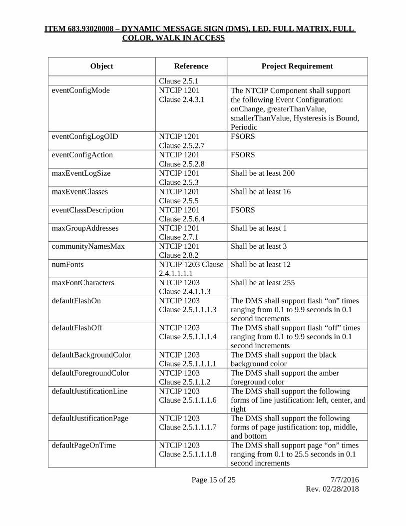
ITEM 683.93020008 – DYNAMIC MESSAGE SIGN (DMS), LED, FULL MATRIX, FULL COLOR, WALK IN ACCESS
Page 15 of 25 7/7/2016 Rev. 02/28/2018
Object Reference Project Requirement
Clause 2.5.1eventConfigMode NTCIP 1201
Clause 2.4.3.1 The NTCIP Component shall support the following Event Configuration: onChange, greaterThanValue, smallerThanValue, Hysteresis is Bound, Periodic
eventConfigLogOID NTCIP 1201Clause 2.5.2.7
FSORS
eventConfigAction NTCIP 1201Clause 2.5.2.8
FSORS
maxEventLogSize NTCIP 1201Clause 2.5.3
Shall be at least 200
maxEventClasses NTCIP 1201Clause 2.5.5
Shall be at least 16
eventClassDescription NTCIP 1201Clause 2.5.6.4
FSORS
maxGroupAddresses NTCIP 1201Clause 2.7.1
Shall be at least 1
communityNamesMax NTCIP 1201Clause 2.8.2
Shall be at least 3
numFonts NTCIP 1203 Clause2.4.1.1.1.1
Shall be at least 12
maxFontCharacters NTCIP 1203Clause 2.4.1.1.3
Shall be at least 255
defaultFlashOn NTCIP 1203Clause 2.5.1.1.1.3
The DMS shall support flash “on” times ranging from 0.1 to 9.9 seconds in 0.1 second increments
defaultFlashOff NTCIP 1203Clause 2.5.1.1.1.4
The DMS shall support flash “off” times ranging from 0.1 to 9.9 seconds in 0.1 second increments
defaultBackgroundColor NTCIP 1203Clause 2.5.1.1.1.1
The DMS shall support the black background color
defaultForegroundColor NTCIP 1203 Clause 2.5.1.1.2
The DMS shall support the amber foreground color
defaultJustificationLine NTCIP 1203Clause 2.5.1.1.1.6
The DMS shall support the following forms of line justification: left, center, and right
defaultJustificationPage NTCIP 1203Clause 2.5.1.1.1.7
The DMS shall support the following forms of page justification: top, middle, and bottom
defaultPageOnTime NTCIP 1203Clause 2.5.1.1.1.8
The DMS shall support page “on” times ranging from 0.1 to 25.5 seconds in 0.1 second increments

ITEM 683.93020008 – DYNAMIC MESSAGE SIGN (DMS), LED, FULL MATRIX, FULL COLOR, WALK IN ACCESS
Page 16 of 25 7/7/2016 Rev. 02/28/2018
Object Reference Project Requirement
defaultPageOffTime NTCIP 1203Clause 2.5.1.1.1.9
The DMS shall support page “off” times ranging from 1.1 to 25.5 seconds in 0.1 second increments
defaultCharacterSet NTCIP 1203Clause 2.5.1.1.1.10
The DMS shall support the eight bit character set
dmsMaxChangeableMsg NTCIP 1203Clause 2.6.1.1.1.4
Shall be at least 100
dmsMessageMultiString NTCIP 1203Clause 2.6.1.1.1.8.3
The DMS shall support any valid MULTI string containing any subset of those MULTI tags listed in Table 3 (below)
dmsControlMode NTCIP 1203Clause 2.7.1.
Shall support at least the following modes: local, central, and centralOverride
dmsSWReset NTCIP 1203Clause 2.7.1.1.1.2
FSORS
dmsMessageTimeRemaining NTCIP 1203Clause 2.7.1.1.1.4
FSORS
dmsShortPowerRecoveryMessage
NTCIP 1203Clause 2.7.1.1.1.8
FSORS
dmsLongPowerRecoveryMessage
NTCIP 1203Clause 2.7.1.1.1.19
FSORS
dmsShortPowerLossTime NTCIP 1203Clause 2.7.1.1.1.10
FSORS
dmsResetMessage NTCIP 1203Clause 2.7.1.1.1.12
FSORS
dmsCommunicationsLossMessage
NTCIP 1203 Clause 2.7.1.1.1.12
FSORS
dmsTimeCommLoss NTCIP 1203Clause 2.7.1.1.1.12
FSORS
dmsEndDurationMessage NTCIP 1203Clause 2.7.1.1.1.15
FSORS
dmsMemoryMgmt NTCIP 1203Clause 2.7.1.1.1.16
The DMS shall support the following Memory Management Modes: normal
clearChangeableMessages clearVolatileMessages
dmsMultiOtherErrorDescription NTCIP 1203Clause 2.4.1.1.1.20
If the vendor implements any vendor-specific MULTI tags, the DMS shall provide meaningful error messages within this object whenever one of these tags generates an error
dmsIllumControl NTCIP 1203Clause 2.8.1.1.1.1
The DMS shall support the following illumination control modes: Photocell, and Manual

ITEM 683.93020008 – DYNAMIC MESSAGE SIGN (DMS), LED, FULL MATRIX, FULL COLOR, WALK IN ACCESS
Page 17 of 25 7/7/2016 Rev. 02/28/2018
Object Reference Project Requirement
dmsIllumNumBrightLevels NTCIP 1203Clause 2.8.1.1.1.4
Shall be at least 100
dmsIllumLightOutputStatus NTCIP 1203Clause 2.8.1.1.1.9
FSORS
numActionTableEntries NTCIP 1203 Clause 2.9.1.1.1
Shall be at least 200
watcdogFailureCount NTCIP 1203Clause 2.11.1.1.1.5
FSORS
dmsStatDoorOpen NTCIP 1203Clause 2.11.1.1.1.6
FSORS
fanFailures NTCIP 1203Clause 2.11.2.1.1.8
FSORS
fanTestActivation NTCIP 1203 Clause 2.11.4.1.1.9
FSORS
tempMinCtrlCabinet NTCIP 1203Clause 2.11.4.1.1.1
FSORS
tempMaxCtrlCabinet NTCIP 1203Clause 2.11.4.1.1.2
FSORS
tempMinSignHousing NTCIP 1203Clause 2.11.4.1.1.5
FSORS
tempMaxSignHousing NTCIP 1203Clause 2.11.4.1.1.6
FSORS
MULTI Tags
Each NTCIP device shall support the following message formatting MULTI tags. The manufacturer may choose to support additional standard or manufacturer-specific MULTI tags.
Table 5: Required MULTI Tags
MULTI Tag Description
f1 Field 1-time (12 hr)
f2 Field 1-time (24 hr)
f8 Field 8-day of month
f9 Field 9-month
f10 Field 10-2 digit year
f11 Field 11-4 digit year

ITEM 683.93020008 – DYNAMIC MESSAGE SIGN (DMS), LED, FULL MATRIX, FULL COLOR, WALK IN ACCESS
Page 18 of 25 7/7/2016 Rev. 02/28/2018
MULTI Tag Description
fl (and/fl) Flashing text on a line-by-line basis with flash rates controllable in 0.1-second increments.
Fo Font
jl2 Justification-line-left
jl3 Justification-line-center
jl4 Justification-line-right
jp2 Justification-page-top
jp3 Justification-page-middle
jp4 Justification-page-bottom
mv Moving text
nl New line
np New page up to 5 instances in a message (i.e. up to 6 pages/frame in a message counting first page)
pt Page times controllable in 0.1-second increments.
Documentation
NTCIP documentation shall be provided on a USB drive and will contain ASCII versions of the following Management Information Base (MIB) files in Abstract Syntax Notation 1 (ASN.1) format:
• The relevant version of each official standard MIB modules referenced by the device functionality.
• If the device does not support the full range of any given object within a standard MIB Module, a manufacturer specific version of the official standard MIB Module with the supported range indicated in ASN.1 format in the SYNTAX and/or DESCRIPTION fields of the associated OBJECT TYPE macro. The filename of this file shall be identical to the standard MIB Module except that it will have the extension “man”.
• A MIB module in ASN.1 format containing any and all manufacturer specific objects supported by the device with accurate and meaningful DESCRIPTION fields and supported ranges indicated in the SYNTAX field of the OBJECT-TYPE macros.
• A MIB containing any other objects supported by the device
Acceptance Testing
The vendor will provide certification of NTCIP-compliance as part of the vendor’s pre-build submittal documentation. This certification shall be in the form of a comprehensive test plan and

ITEM 683.93020008 – DYNAMIC MESSAGE SIGN (DMS), LED, FULL MATRIX, FULL COLOR, WALK IN ACCESS
Page 19 of 25 7/7/2016 Rev. 02/28/2018
completed test report as performed by either the vendor or a third-party testing agency. The testing shall have been completed using industry accepted test tools such as the NTCIP Exerciser, Trevilon’s NTester, Intelligent Devices’ Device Tester, and/or Frontline’s FTS for NTCIP. Data capture files from the FTS software during the performance of the above testing shall be furnished upon request of the Engineer.
The Engineer can elect to perform additional NTCIP testing if desired. This testing shall be conducted on a production DMS in the vendor’s facility during the factory acceptance test. The vendor shall provide a written NTCIP test procedure to the Engineer a minimum of 30 days prior to the NTCIP testing.
Interpretation Resolution
If the Engineer or DMS manufacturer discovers an ambiguous statement in the standards referenced by this procurement specification, the issue shall be submitted to the NTCIP DMS Working Group for resolution. If the Working Group fails to respond within 90 days, the engineer shall provide an interpretation of the specification for use on the project.
INTELLECTUAL PROPERTY RIGHTS:
The manufacturer shall allow the use of any and all of this documentation by any party authorized by the Procuring Agency for systems integration purposes at any time initially or in the future, regardless of what parties are involved in the systems integration effort.
CENTRAL SOFTWARE:
Unless otherwise specified in the contract plans, the Contractor shall supply DMS central control software necessary to interface sign functions remotely from the Regional TMC. All control software shall be delivered on a USB 3.0 or better thumb drive. and installed on the DMS computer and workstations as directed by the Regional TMC Systems Manager. The TMC should be contacted for specifics of the communications protocols and software in place.
DMS software shall comply with the National Transportation Communications for ITS Protocol (NTCIP) documents and all related amendments, effective September 2008, and as referenced herein. The software shall be of a client-server design, in which users can connect to, configure, monitor, and control signs from workstations in the TMC and also from workstations connected to the DMS computer by a TCP/IP 100-BaseT network. Some workstations may use dial-up telephone lines or other low-speed connections to reach the network via the LAN server. The DMS computer shall communicate with the signs via either multipoint EIA-232 communication channels or over TCP/IP Ethernet protocol. The DMS central software shall support at least 60 users and workstations, and 999 signs.
The software shall provide the following capabilities to users at the workstations and DMS computer:
• See a list of messages stored in the sign or on the sign controller with an indication of which is currently being displayed on the monitor screen exactly as it appears to motorist.
• Cause a different message to be displayed.
• Upload and download new message files between the sign controllers and the DMS computer.

ITEM 683.93020008 – DYNAMIC MESSAGE SIGN (DMS), LED, FULL MATRIX, FULL COLOR, WALK IN ACCESS
Page 20 of 25 7/7/2016 Rev. 02/28/2018
• Automatically detect malfunctions, including loss of communication or power, and errors.
• Create and edit fonts and messages and storing them on the DMS computer’s disk drive for subsequent downloading to one or more signs.
• Create an activity log for all signs.
• Allow existing, or future, NTCIP based signs to be incorporated, configured, controlled, and monitored.
• On screen notification/alarm of cabinet door open, malfunctions, errors, and out of range environmental conditions.
CONSTRUCTION DETAILS:
The DMS will be installed on new or existing sign structures as shown in the contract documents. Posts, post foundations, and other supporting structures shall be paid for under other contract items as shown in the plans.
The Contractor shall develop and deliver shop drawings which illustrate, in detail, how to mount and connect the sign enclosure to the appropriate support structure shown on the plans. All shop drawings shall be certified by a licensed N.Y.S. Professional Engineer and shall be submitted to the Department in accordance with Section 730-27 of the Standard Specifications. The sign enclosure shall be attached so that the sign face will be tilted down at an angle of 5 degrees to diminish sun glare.
The sign shall not be mounted to the sign structure until all power and communication lines have been brought to the site and are ready for connection to the sign.
Installation Certification
All controller(s), LED display modules, and mounting hardware shall be installed in accordance with manufacturer’s instructions and recommendations. To ensure the sign was installed properly the Contractor shall submit to the Engineer documentation which that states either a.) the manufacturer, or the manufacturer’s authorized supplier, verifies that the Contractor has been trained on the installation, operation, testing and maintenance of the equipment or b) provides documentation from the manufacturer that the installation has been inspected and approved by the manufacturer or authorized representative.
Testing Requirements
Test Plan
The manufacturer shall provide a test plan, 30-days prior to each test, for review and approval by the Engineer, for each of the three types of acceptance testing required: Design Acceptance Testing, Stand-alone Acceptance Testing, and System Acceptance Testing.
The test plans shall clearly identify each function and element being tested, the setup conditions, the steps to be followed during the test, and the anticipated test results. The test plan shall exercise all required functions and capabilities under this item.
The following is a typical, but non-exhaustive list of the type of requirements that the test plan shall verify:

ITEM 683.93020008 – DYNAMIC MESSAGE SIGN (DMS), LED, FULL MATRIX, FULL COLOR, WALK IN ACCESS
Page 21 of 25 7/7/2016 Rev. 02/28/2018
• Downloading, uploading, displaying, entering, editing, and deleting sign messages and fonts.
• Displaying of all characters, all messages, and all symbols on the sign.
• Switching between several different messages and flashing a part of a message.
• Recovery from simulated communications errors, simulated watchdog timer errors, and simulated sign controller errors.
• Demonstration of the operation of the thermostatically controlled fans, automatic LED temperature shutdown and dimming, and environmental warnings.
• Demonstration of automatic restart after a simulated short-term and simulated long term power failure.
• Demonstration of the operation of the variation of the LED intensity based on various levels of ambient light.
• Test the lockout/tagout disconnect switch.
Test Equipment
The test plan shall identify all equipment required to perform the tests. This equipment shall be provided by the Contractor for the duration of the testing program. As a minimum, functional testing equipment shall include the latest version of the Device Tester for NTCIP, software by Intelligent Devices Inc, or approved equal.
Test Performance
The test shall be coordinated with NYSDOT at least three (3) weeks prior to the actual date. The Contractor shall conduct all tests, in the presence of the Engineer and/or up to two (2) other representatives. The Engineer may waive the right to witness certain tests. The utilized software shall be in recording/capturing mode while performing the test procedures.
Test Reports
The Contractor shall maintain a complete record of each test performed including the results of the test and a record of who witnessed the test. At the completion of each test, the test documentation shall be completed and provided to the Engineer for review. This documentation shall be the basis for acceptance or rejection by the Engineer. All test reports shall be signed by the Contractor’s authorized testing representative.
Test Failure
The unit shall be corrected or another unit substituted in its place and the test successfully repeated. The substitute unit shall have passed all other tests successfully. If any DMS equipment or software/firmware modifications are necessary as a result of any test or demonstration failure, full retesting for compliance with these specifications may be required and a test report shall be prepared and delivered to the Engineer prior to retesting of the equipment. The report shall describe the nature of the failure and corrective action taken. If a failure pattern, as defined by the Engineer, develops, the Engineer may direct that design and construction modifications be made to all units without additional cost to the State, other involved agencies, or extension of the contract period

ITEM 683.93020008 – DYNAMIC MESSAGE SIGN (DMS), LED, FULL MATRIX, FULL COLOR, WALK IN ACCESS
Page 22 of 25 7/7/2016 Rev. 02/28/2018
Test Specifics
Design Approval Test
Design approval tests shall be conducted by the Contractor on one or more sample equipment of each type, as approved by the Engineer, to determine if the design of the equipment meets the requirements of this specification. The tests shall be conducted in accordance with the approved test procedures. Tests shall be conducted between -35 degrees F and +165 degrees F.
In the case of standard product line equipment, the Engineer may waive the design approval tests if the manufacturer's written specifications (functional and environmental) are equal to or better than those specified herein and he so states in writing or if the Contractor provides certification by an independent testing laboratory that these design approval tests have been previously satisfactorily completed. The design approval test shall cover the following at a minimum:
Temperature:
All functional operations of the equipment shall be successfully performed under the following conditions and in the order specified below:
The equipment shall be stabilized at 32ºF. After stabilization at this temperature, the equipment shall be operated without degradation for 2 hours.
The equipment shall be stabilized at 122ºF. After stabilization, the equipment shall be operated without degradation for 2 hours.
Relative Humidity:
All equipment shall meet is performance requirements when subjected to temperature and relative humidity of 122ºF and 70 % respectively. The equipment shall be maintained at the above condition for 48 hours. At the conclusion of the soak, within 30 minutes the equipment shall meet all of its operation requirements.
Power Variation:
The equipment shall meet all of the specified performance requirements when the input voltage is plus or minus 10 volts from the nominal value of 115 volts. The equipment shall be operated at the extreme limits for at least 15 minutes during which it shall meet all of its operation requirements.
Vibration:
The equipment shall show no degradation of mechanical structure, soldered components, plug-in components or satisfactory operation in accordance with the manufacturer's specification after being subjected to the following vibration test:
The equipment shall be secured to the (shaker) head of suitable electro-mechanical shaker in the vertical, lateral and longitudinal planes respectively. The object of the test is to vibrate the equipment in each of the three mutually perpendicular axes, in accordance with the following parameters:
• Amplitude - 0.06 “Double Amplitude” (peak-to-peak).
• Linear Acceleration (g’s) - 5 maximum.
• Linear Velocity - approximately 7 inches per second.

ITEM 683.93020008 – DYNAMIC MESSAGE SIGN (DMS), LED, FULL MATRIX, FULL COLOR, WALK IN ACCESS
Page 23 of 25 7/7/2016 Rev. 02/28/2018
• Frequency - 40 Hz.
• Duration - 5 minute dwell in each axis.
If the equipment fails the design approval test, the design fault shall be corrected and the entire design approval test shall be repeated. All deliverable equipment shall be modified, without additional cost to the Department, to include design changes required to pass the design approval tests.
On-Site Stand-Alone and System Performance Test
The Contractor shall conduct approved stand-alone tests of the equipment installed in the field and at the TMC. The tests shall, as a minimum, exercise all stand-alone (non-network) functional operations of the field equipment, including NTCIP compliance, and TMC equipment and software with all the equipment installed per the plans as directed by the Engineer. Approved data forms shall be completed and turned over to the Engineer as the basis for review and rejection or acceptance.
Each unit of equipment shall be operated long enough to permit equipment temperature stabilization, and to check and record an adequate number of performance characteristics to ensure compliance with the requirements of this specification. The test shall, as a minimum, exercise all the input and output functions of the unit and demonstrate all operational features.
Following successful completion of the On-Site Stand-Alone tests the entire complement of subsystems and equipment shall be integrated into one system. Interface tests shall then be performed to verify the transfer of information between field equipment elements and the TMC.
System performance testing shall exercise all functional operations of each unit of field equipment from the TMC, and demonstrate compliance with all contract requirements.
The tests shall include multiple combinations of functions including infrequent combinations, input validation, and stress testing. Compliance with all performance requirements shall be demonstrated. Where there are multiple units of the same item of equipment used, compliance with performance parameter requirements may be demonstrated on sample units with approval of the Engineer.
If the equipment fails the stand-alone test, it shall be corrected or another substituted in its place and the test successfully repeated.
In addition to the Stand-Alone Test defined above, once installed the sign controller must pass a test of the NTCIP Compliance as specified herein. The test will be performed by Department personnel or their designee using Intelligent Devices NTCIP testing software or another testing package. Prior to testing, the test scripts will be viewable by the Contractor and the manufacturer. During the test it is expected that the Contractor, manufacturer, and Department’s Construction inspection firm will be present. The date, location, and time of the test will be designated by the Department.
NOTE: The sign controller must pass this test in order to be accepted. If the manufacturer can prove that the Department has tested the exact VMS Controller, Software, Firmware, and system software using the above method, then this item may be waived at the sole discretion of the Department.

ITEM 683.93020008 – DYNAMIC MESSAGE SIGN (DMS), LED, FULL MATRIX, FULL COLOR, WALK IN ACCESS
Page 24 of 25 7/7/2016 Rev. 02/28/2018
90-Day Operational Test (Final Acceptance Test)
Following successful completion of the system performance tests, a 90-calendar day test shall be performed. The test shall start at the same time for all system elements unless a waiver is received from the Engineer.
The 90-day test will be run from the TMC. Each sign must successfully connect 95% of the time during the test period. During this time the following tests, at a minimum, must occur:
• A daily test of communicating to each sign
• A daily test message, using 2-panels, will be correctly displayed on each sign and this will be verified by visual inspection (observation).
• Once a week a detailed pixel test will occur. This test will include, but is not limited to, All ON, 10% brightness, etc.
The purpose of the Operational Tests is to demonstrate the reliability of system equipment for a 90-day period. In the event of a failure of any contractor supplied components, or of any existing system elements that may be affected, that portion of the system shall be subjected to an additional 30-day test period. Failure shall be defined as any interruption of operation that can be contributed to the DMS components. If a failure occurs, the test shall be stopped until the failure has been resolved. If the same failure occurs three (3) times, the failure shall be resolved and the 90-day test shall begin anew.
In the event that greater than 20% of similar equipment items malfunction during the test period, the Engineer may declare a system defect and require replacement of all items of that equipment.
When a system defect is declared, the 90-day test period shall be restarted for the affected equipment after replacement.
During the Operational Test period the Contractor shall provide support for all installed equipment including problem troubleshooting and replacement of items not operating as specified. The Contractor shall maintain detailed daily records in the form of a maintenance and activity log. The log shall include the identity of equipment on which work is performed, the cost of equipment malfunction, if any, a description of the work performed, materials or special equipment used and the time required to complete the activity. The log shall contain the current test status of all equipment items. The maintenance and activity log shall be available to the Engineer upon request.
The final acceptance shall be based on the satisfactory completion of all 90-Day tests.
Training Requirements
Contractor Training
Prior to the installation of any specified equipment, the Contractor’s personnel shall have received training from the supplier on installation, operations, testing and maintenance of all equipment. No equipment will be accepted without detailed documentation from the equipment supplier certifying that the training has taken place.
NYSDOT Training
Unless otherwise specified on the contract plans, the contractor and/or DMS manufacture shall be responsible for providing a one (1) day training seminar in the operations and maintenance of the

ITEM 683.93020008 – DYNAMIC MESSAGE SIGN (DMS), LED, FULL MATRIX, FULL COLOR, WALK IN ACCESS
Page 25 of 25 7/7/2016 Rev. 02/28/2018
DMS for NYSDOT management, engineering, operations, and maintenance personnel. The contractor shall contact the Engineer to verify the requirements and number of personnel scheduled for training. Training sessions shall be conducted at the TMC and in the field, consisting of both classroom and “hands-on” training using installed system equipment.
Training shall not exceed 8 hours with a maximum of twelve students. The Contractor shall submit two copies of the course outline, training materials, and instructors’ qualifications to the Engineer for approval 30 calendar days prior to the anticipated start of training. Following approval of the material the Contractor shall submit enough copies of the course material for use by the NYSDOT during the training program.
The costs for instructors, course materials, handouts, etc. shall be included in the costs of this item. No separate payment for training will be made to the Contractor.
METHOD OF MEASUREMENT:
The DMS will be measured for payment as each unit installed, tested, and made fully operational.
BASIS OF PAYMENT:
The unit price bid for each DMS shall include the cost of furnishing all labor, materials, tools, software, equipment and incidentals as necessary to complete the work. This includes hardware necessary for mounting the DMS to the support structure. Power and communication cables from sign controller to the DMS are also included.
Communications devices and associated patch cords will be paid under separate bid items.
Primary sign support structures such as heavy posts, concrete foundations, bridge mount frames, and other structures supporting the sign shall be paid for under other contract items as shown on the contract plans.
Walk in access platforms, including ladder access & safety chains to be paid under separate bid items.
Ground-mounted field equipment cabinet that houses the DMS controller, panel board, 120 VAC electrical outlets and remote communication devices will be paid under separate bid items.
Progress payment will be made as follows:
Fifty percent (50%) of the bid price of each item will be paid when it is installed.
Forty percent (40%) of the bid price will be paid upon satisfactory completion of the On-Site Stand-Alone and System Performance Test.
Ten percent (10%) of the bid price will be paid upon satisfactory completion of the 90 Day Operational Test.

ITEM 800.01000015 – DESIGN BUILD – DESIGN SERVICES
Page 1 of 1 2/7/2012
DESCRIPTION. This work shall consist of providing design services in accordance with the contract documents. MATERIALS. None Specified. CONSTRUCTION DETAILS. The Design Builder shall provide Design Services by the appropriately qualified and licensed personnel in accordance with the requirements in the contract documents. METHOD OF MEASUREMENT. Design Build - Design Services will be measured for payment on a lump sum basis. BASIS OF PAYMENT. The lump sum price bid for Design Build - Design Services shall include the cost of furnishing all labor, equipment and incidentals to satisfactorily complete the work. Progress payments will be made in accordance with the contract documents.

ITEM 800.02000015 – DESIGN BUILD – CONSTRUCTION INSPECTION SERVICES
Page 1 of 1 2/7/2012
DESCRIPTION. This work shall consist of providing Construction Inspection Services in accordance with the contract documents. MATERIALS. None Specified. CONSTRUCTION DETAILS. The Design Builder shall provide Construction Inspection Services by the appropriately qualified and licensed personnel in accordance with the requirements in the contract documents. METHOD OF MEASUREMENT. Design Build - Construction Inspection Services will be measured for payment on a lump sum basis. BASIS OF PAYMENT. The lump sum price bid for Design Build - Construction Inspection Services shall include the cost of furnishing all labor, equipment and incidentals to satisfactorily complete the work. Progress payments will be made in accordance with the contract documents.

ITEM 800.03000015 – DESIGN BUILD – QUALITY CONTROL SERVICES
Page 1 of 1 2/7/2012
DESCRIPTION. This work shall consist of providing Quality Control Services in accordance with the contract documents. MATERIALS. None Specified. CONSTRUCTION DETAILS. The Design Builder shall provide Quality Control Services by the appropriately qualified and licensed personnel in accordance with the requirements in the contract documents. METHOD OF MEASUREMENT. Design Build - Quality Control Services will be measured for payment on a lump sum basis. BASIS OF PAYMENT. The lump sum price bid for Design Build - Quality Control Services shall include the cost of furnishing all labor, equipment and incidentals to satisfactorily complete the work. Progress payments will be made in accordance with the contract documents.

ITEM 800.04000015 – DESIGN BUILD – FORCE ACCOUNT WORK
Page 1 of 1 Rev. Oct. 2013
DESCRIPTION. This work shall consist of performing construction work in accordance with the contract documents and as directed by the Engineer. MATERIALS. None Specified. CONSTRUCTION DETAILS. The Design Builder shall perform construction work in accordance with the contract documents as directed by the Engineer. The Design Builder will maintain and provide agreed price or force account records to document the costs in accordance with DB section 109-9. METHOD OF MEASUREMENT. Design Build – Force Account Work will be measured for payment on a Dollar Cents basis. BASIS OF PAYMENT. The price shown for Design Build - Force Account Work shall include the cost of furnishing all labor, materials, equipment and incidentals to satisfactorily complete the work. The total cost shown in the itemized proposal will be considered the price bid even though payment will be made only for actual work performed. The unit price amount is not to be altered in any manner by the bidder. Should the bidder alter the amount shown, the altered figure will be disregarded, and the original price will be used to determine the total amount bid for the contract. Progress payments will be made in accordance with the contract documents.

ITEM 800.05000015 – DESIGN BUILD – SITE MOBILIZATION
Page 1 of 1 2/13/2012
DESCRIPTION. This work shall consist of providing necessary bonds, insurance, prefinancing and set up of necessary general plant, including shops, storage areas, office and such sanitary and other facilities as are required by local or state law or regulation. MATERIALS. None Specified. CONSTRUCTION DETAILS. The Design Builder shall provide the above facilities and service for mobilization in a safe and workmanlike manner in conformance with any pertinent local or State Law, regulation or code to the extent and at the time the Contractor deems them necessary for its operations. Good housekeeping shall be maintained. METHOD OF MEASUREMENT. Design Build – Site Mobilization will be measured for payment on a lump sum basis. BASIS OF PAYMENT. The lump sum price bid for Design Build – Site Mobilization shall not exceed four percent (4%) of the total contract bid price for all Construction Work items. Should the bidder exceed the foregoing four percent (4%), the Department will make the necessary adjustment to determine the total amount bid based on the arithmetically correct proposal. Progress payments in the amount of 4% of the construction work items will be made to the Contractor with the first contract payment made for other contract work at the individual itemized work site.

ITEM 800.0600NN15 – DESIGN BUILD – CONSTRUCTION WORK
Page 1 of 1 2/13/2012
DESCRIPTION. This work shall consist of construction work in accordance with the contract documents. MATERIALS. None Specified. CONSTRUCTION DETAILS. The Design Builder shall perform all construction work in accordance with the requirements in the contract documents. METHOD OF MEASUREMENT. Design Build – Construction Work will be measured for payment on a lump sum basis for each location. The individual locations are identified in the contract documents. BASIS OF PAYMENT. The lump sum price bid for Design Build – Construction Work shall include the cost of furnishing all labor, materials, equipment, management and supervision to satisfactorily complete the work. Progress payments will be made for each construction work location in accordance with the contract documents. Note: NN in pay item number denotes serialization by location.


![Total Solution for Oil and Gas Testing [ZH] · 2019-03-20 · astm d3710 astm d7096 astm d5399 astm d2887 astm d5442 astm d7213 astm d6417 astm d6352 astm d5307 astm d7500 astm d7169](https://img.dokumen.tips/doc/110x75/5e70c2f4b4ab9c1c733fd110/total-solution-for-oil-and-gas-testing-zh-2019-03-20-astm-d3710-astm-d7096-astm.jpg)