Embed Size (px)
Citation preview

Daya Bay, Physically
VTcentric
Complied by Jo Ellen Narron

Location
U.S.:
BNL, Caltech, Cincinnati, George Mason, Houston, IIT, Iowa State, LBNL, Princeton, RPI, UC Berkeley UCLA, UIUC, Virginia Tech, Wisconsin
Asia:
Beijing Normal, Chengdu U. of Tech., CGNPE, CIAE, CUHK, Dongguan Polytech, IHEP Beijing, Nankai, Nanjing, National Chiao-Tung U., National Taiwan U., National United U., Shangdong U., SJTU, Shenzhen U., Tsinghua U., HKU, USTC, Zhongshan U.
Europe.:
Charles U., JINR, Kurchatov Institute
The Daya Bay Collaboration
Jon Link Dayabay at LowNu 2009


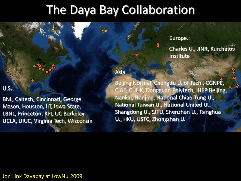
Daya Baycores
Ling Aocores
Ling Ao IIcores
Daya Bay NearOverburden: 98 m
Ling Ao NearOverburden: 112 m
Far siteOverburden: 355 m
Daya Bay: Experimental setup • 8 identical anti-neutrino detectors ( two at each near site and four at the far site) to cross-check detector efficiency• Two near sites sample flux from reactor groups
Daya Bay Near (m)
Ling AoNear (m)
Far (m)
Daya Bay 363 1347 1985
Ling Ao I 857 481 1618
Ling Ao II 1307 526 1613
(Starting 2011)
9 different baselines under the assumption
of point size reactor cores and detectors
CoresHalls
Deb Mohapatra Meeting of APS Division of Particles & Fields

Ehs & Water Pools
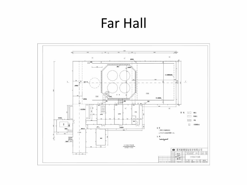
Far Hall
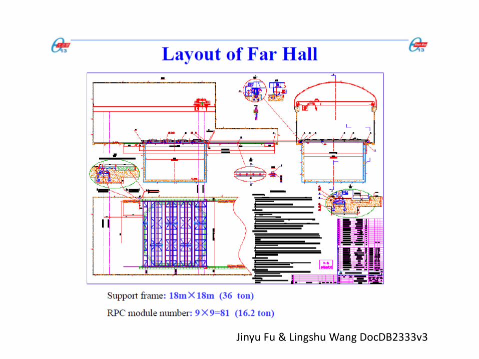
Jinyu Fu & Lingshu Wang DocDB2333v3

Near Daya Bay Hall

Near Ling Ao Site
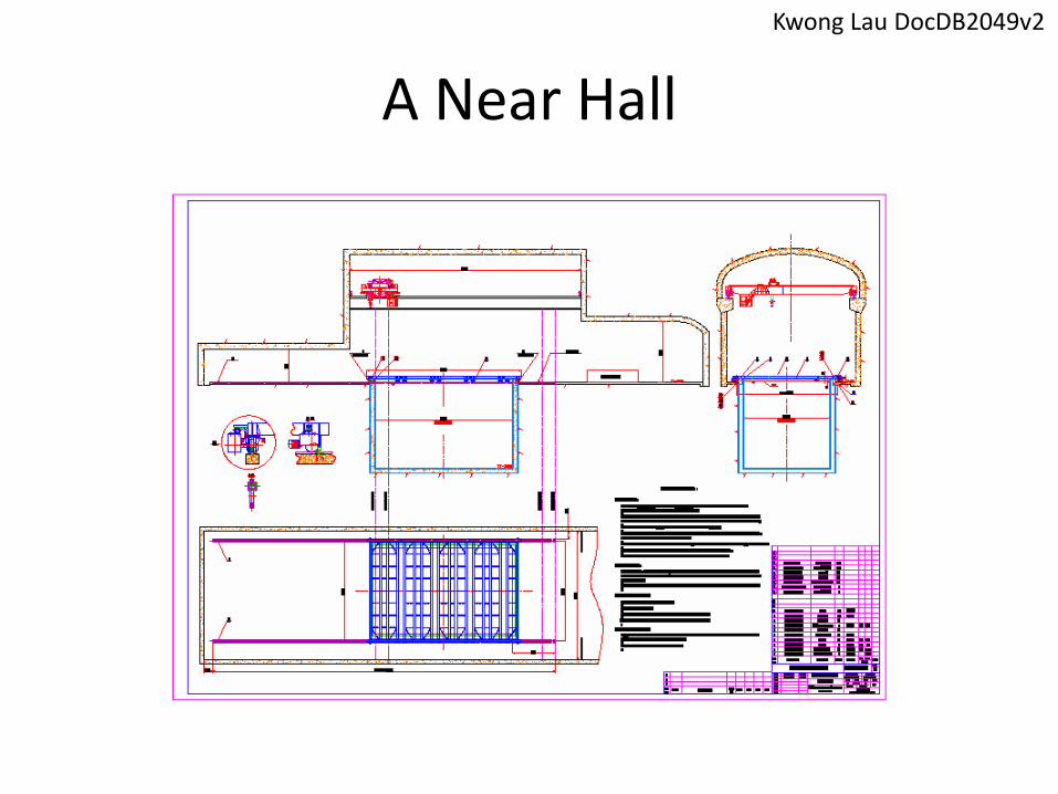
A Near Hall
Kwong Lau DocDB2049v2
13
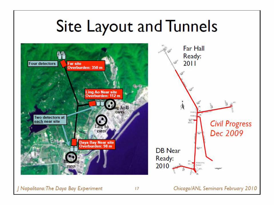
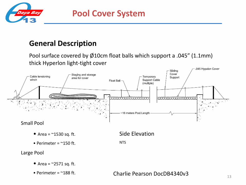
Pool Cover System
General Description
Pool surface covered by Ø10cm float balls which support a .045” (1.1mm) thick Hyperlon light-tight cover
Side Elevation
NTS
Small Pool
• Area = ~1530 sq. ft.
• Perimeter = ~150 ft.
Large Pool
• Area = ~2571 sq. ft.
• Perimeter = ~188 ft. Charlie Pearson DocDB4340v3

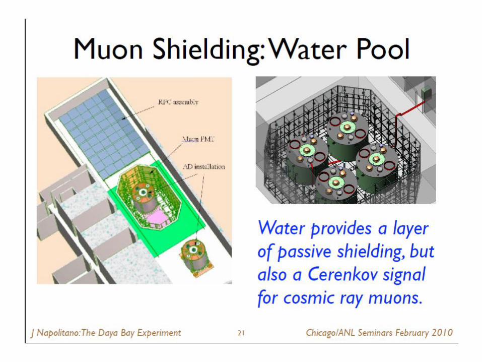
Muon veto system
CerenkovWater Pool (2 Zone)
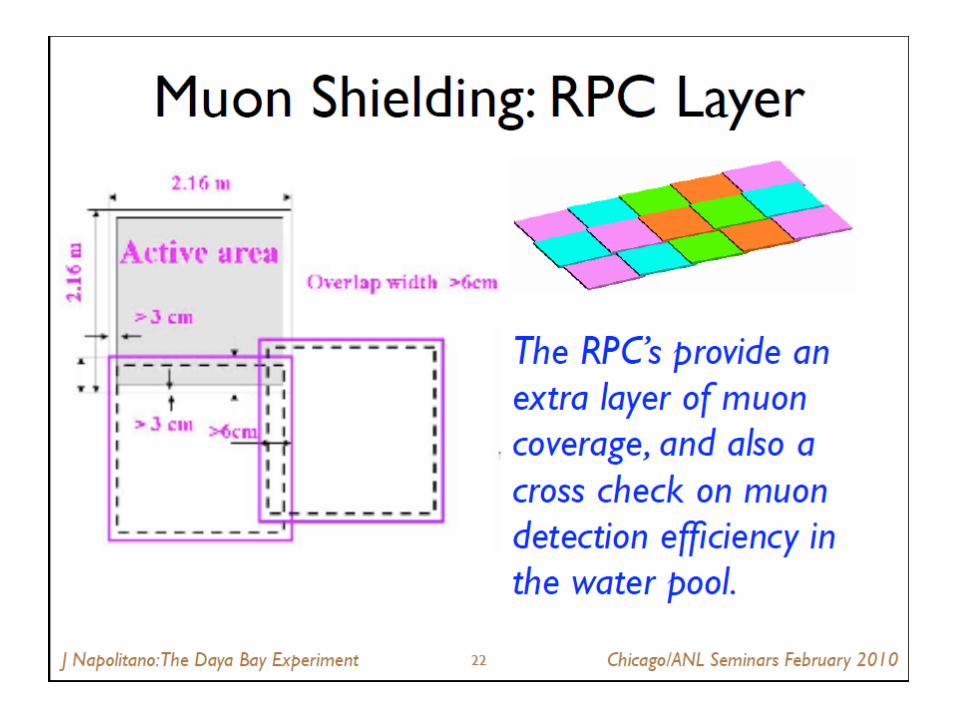
RPC’s
PMTs(962)
• Two tagging systems to detect cosmic ray and fast neutron background: 2.5 meter thick two-section water shield and RPCs
• Efficiency 99.5% with uncertainty <0.25%
Deb Mohapatra Meeting of APS Division of Particles & Fields

Water Shield and Muon Tagging System
Water Pool
RPCs
The water pool shields the detectors from energetic γ-rays from the decay chains of 238U, 232Th and 40K in surrounding the rock
It also detects the Čerenkov light produced by cosmic ray muons which pass near the detectors
The pool is lined with white Tyvek and sparsely populated with PMTs
The pool is optically separated into two zones (inner and outer)
The two zones allow a better measurement of efficiency
The top is covered with 4 layers of RPC Minimum 2.5 m water shielding in
all directions.
Construction of the water pool at the Daya Bay Near site
Jon Link Dayabay at LowNu 2009
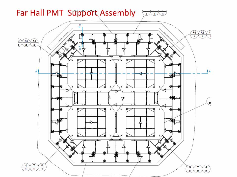
Far Hall PMT Support Assembly
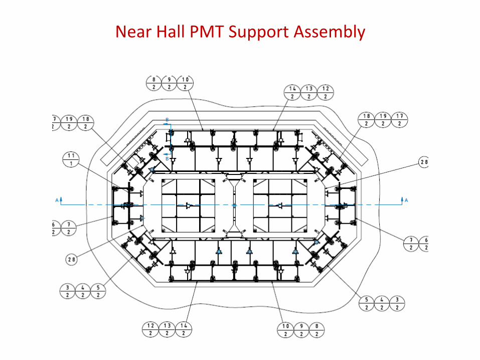
Near Hall PMT Support Assembly
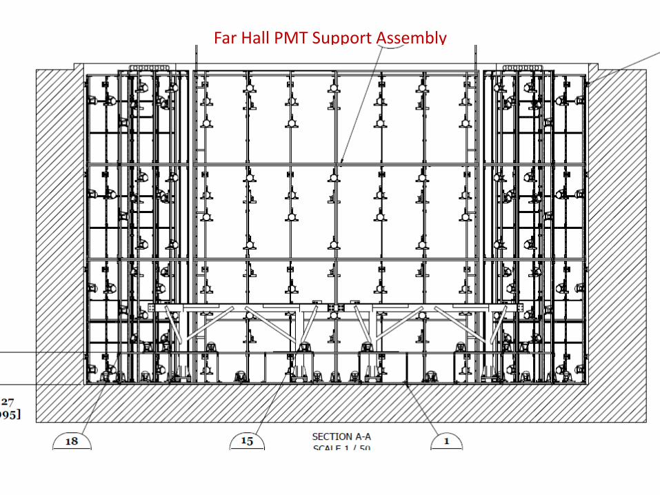
Far Hall PMT Support Assembly
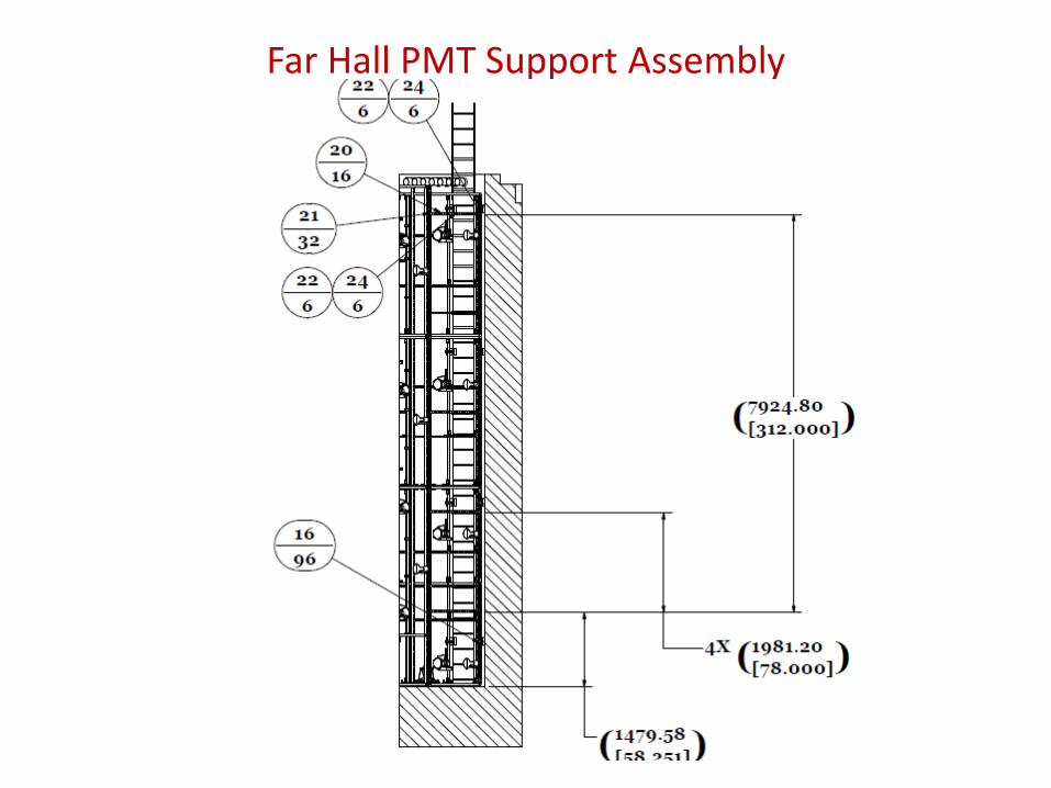
Far Hall PMT Support Assembly
Muon Calibrationaka: muCal
One of VT’s Major efforts, we are responsible for the calibration of the
PMTs in the water pool.


RPCs & Support
VTs other major effort is the development of the RPC HV system
35
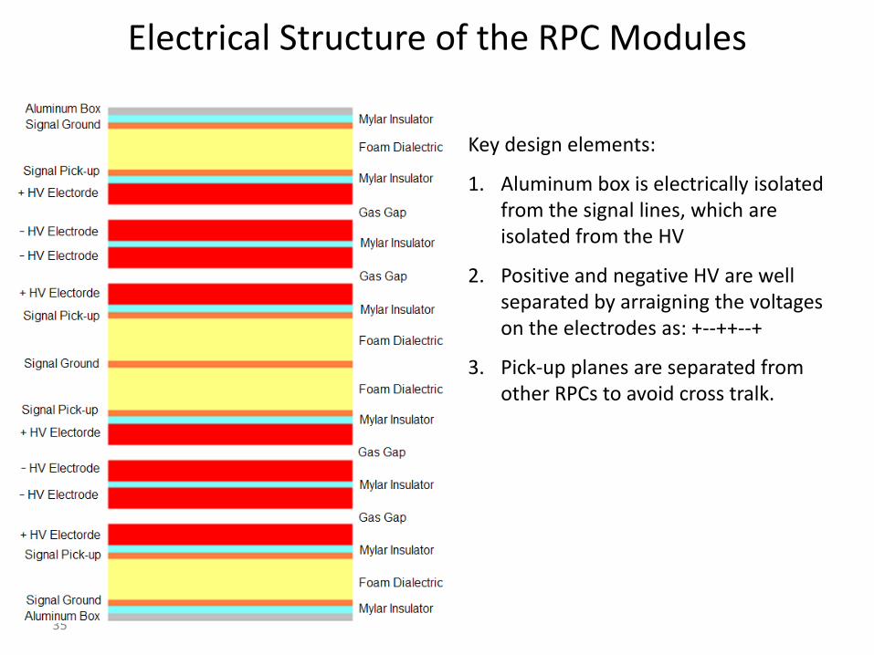
Electrical Structure of the RPC Modules
Key design elements:
1. Aluminum box is electrically isolated from the signal lines, which are isolated from the HV
2. Positive and negative HV are well separated by arraigning the voltages on the electrodes as: +--++--+
3. Pick-up planes are separated from other RPCs to avoid cross tralk.
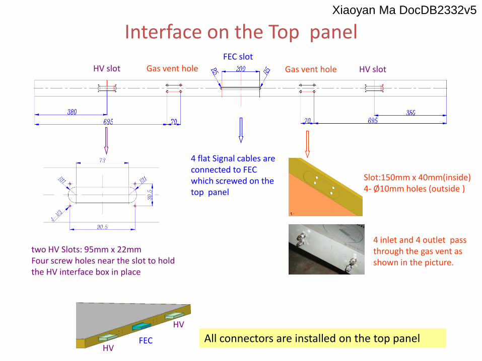
Interface on the Top panel
All connectors are installed on the top panel
two HV Slots: 95mm x 22mmFour screw holes near the slot to hold the HV interface box in place
HV slotHV slot
FEC slot
Gas vent hole Gas vent hole
4 flat Signal cables are connected to FEC which screwed on the top panel
HV
FECHV
Slot:150mm x 40mm(inside) 4- Ø10mm holes (outside )
4 inlet and 4 outlet pass through the gas vent as shown in the picture.
Xiaoyan Ma DocDB2332v5
37
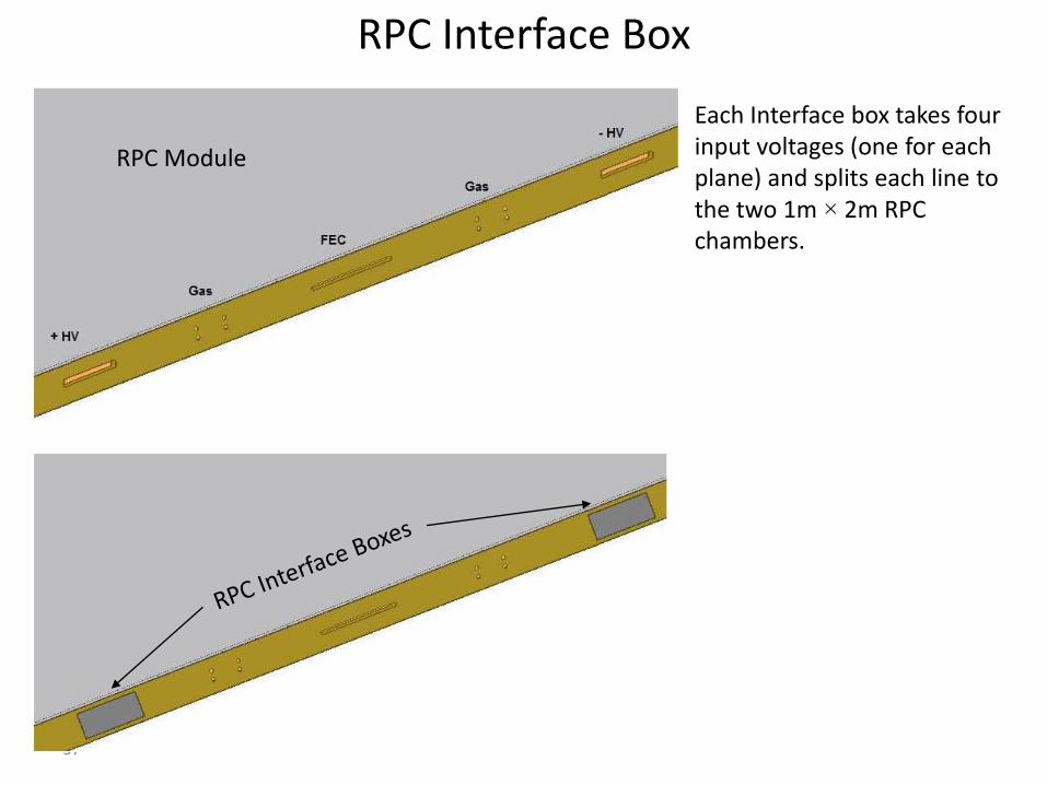
RPC Interface Box
RPC Module
Each Interface box takes four input voltages (one for each plane) and splits each line to the two 1m × 2m RPC chambers.

Kwong Lau DocDB2049v2


Flexible cable tray to avoid disconnecting the cables
• The configuration of the flexible cable tray is shown in the above plot,
• One end of the flexible cable tray is fixed at the trench , the other end is fixed at the center of RPC support structure, (details in next slides)
• Given R=0.2m, offset=1m, we need 12.3m flexible cable tray for each site,
• The RPC’s will move as a single unit except for repairing.
Far site pool
Total Length = 9.65m + π*R+ 2*offset
R is the bending radius,
Offset gives convenience to installation
Mengyun Guan & Changgen Yang DocDB2370v5

Pool Cover 42
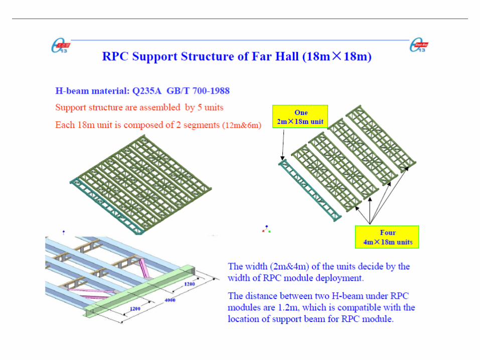
RPC Support Structure
Black Polypropylene float ball
Veto PMTs Unistrut Support Frame
Cable Trench
Side Elevation in Section
Charlie Pearson DocDB4340v3

RPC Structure PRR and Module FDR
Introduction
Changgen Yang
24 June 2008
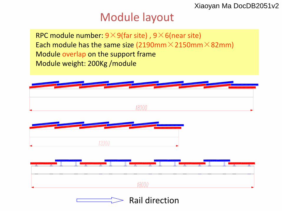
RPC module number: 9×9(far site) , 9×6(near site)Each module has the same size (2190mm×2150mm×82mm)Module overlap on the support frameModule weight: 200Kg /module
Module layout
Rail direction
Xiaoyan Ma DocDB2051v2
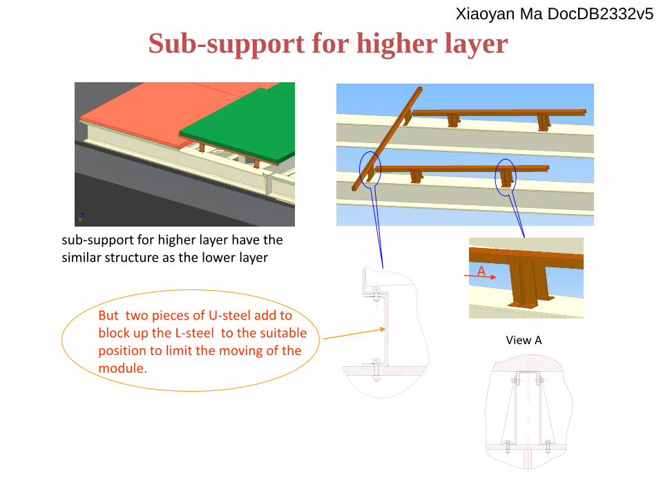
Sub-support for higher layer
sub-support for higher layer have the similar structure as the lower layer
But two pieces of U-steel add to block up the L-steel to the suitable position to limit the moving of the module.
A
View A
Xiaoyan Ma DocDB2332v5
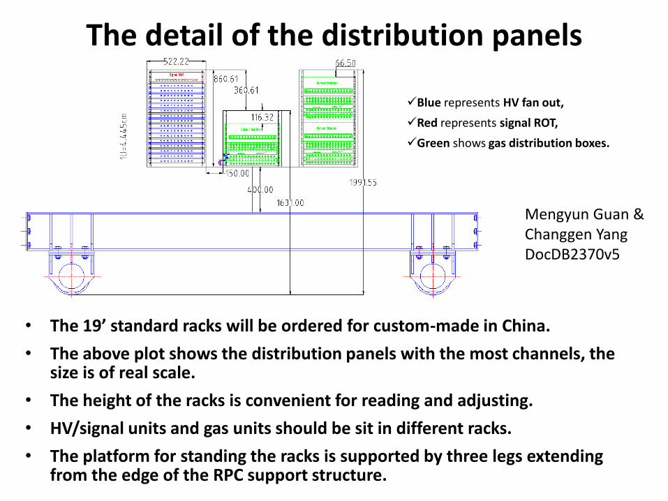
The detail of the distribution panels
• The 19’ standard racks will be ordered for custom-made in China.
• The above plot shows the distribution panels with the most channels, the size is of real scale.
• The height of the racks is convenient for reading and adjusting.
• HV/signal units and gas units should be sit in different racks.
• The platform for standing the racks is supported by three legs extending from the edge of the RPC support structure.
Blue represents HV fan out,
Red represents signal ROT,
Green shows gas distribution boxes.
Mengyun Guan & Changgen YangDocDB2370v5
Cable/tube routing detail
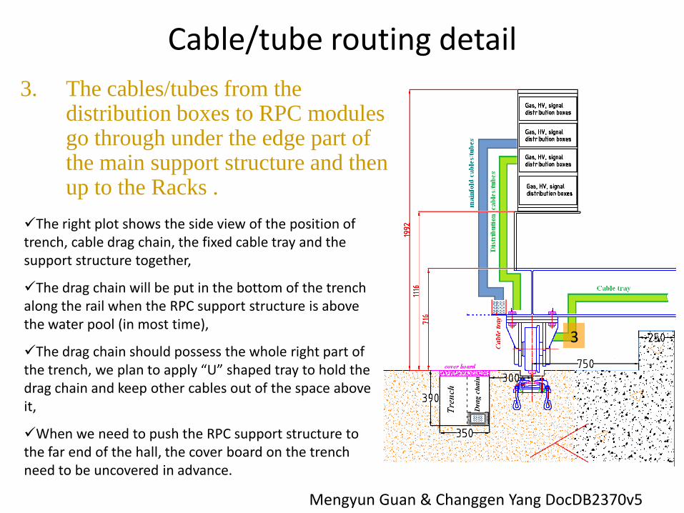
3. The cables/tubes from the distribution boxes to RPC modules go through under the edge part of the main support structure and then up to the Racks .
The right plot shows the side view of the position of trench, cable drag chain, the fixed cable tray and the support structure together,
The drag chain will be put in the bottom of the trench along the rail when the RPC support structure is above the water pool (in most time),
The drag chain should possess the whole right part of the trench, we plan to apply “U” shaped tray to hold the drag chain and keep other cables out of the space above it,
When we need to push the RPC support structure to the far end of the hall, the cover board on the trench need to be uncovered in advance.
3
Mengyun Guan & Changgen Yang DocDB2370v5

The overall scheme of the distribution panels
• The RPC gas monitor chamber & driving control crate is putting together with the gas/HV/sig distribution devices,
• The HV fan out panel and the gas distribution panel are of the latest picture, while the ROT is still unknown.
Mengyun Guan & Changgen Yang DocDB2370v5
Cable/tube routing detail
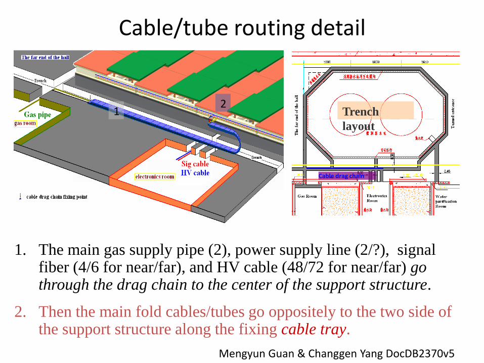
1. The main gas supply pipe (2), power supply line (2/?), signal fiber (4/6 for near/far), and HV cable (48/72 for near/far) go through the drag chain to the center of the support structure.
2. Then the main fold cables/tubes go oppositely to the two side of the support structure along the fixing cable tray.
12
Trench
layout
Cable drag chain
Mengyun Guan & Changgen Yang DocDB2370v5

52
A1733P(N)
12 channels
+(-) 4 kV
2 mA
No floating return
CAEN Hardware
SY1527LC
Same mainframe as used for the PMT HV
16 slots
Fan Out
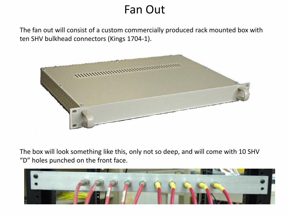
The fan out will consist of a custom commercially produced rack mounted box with ten SHV bulkhead connectors (Kings 1704-1).
The box will look something like this, only not so deep, and will come with 10 SHV “D” holes punched on the front face.
54
High Voltage Multiplexing
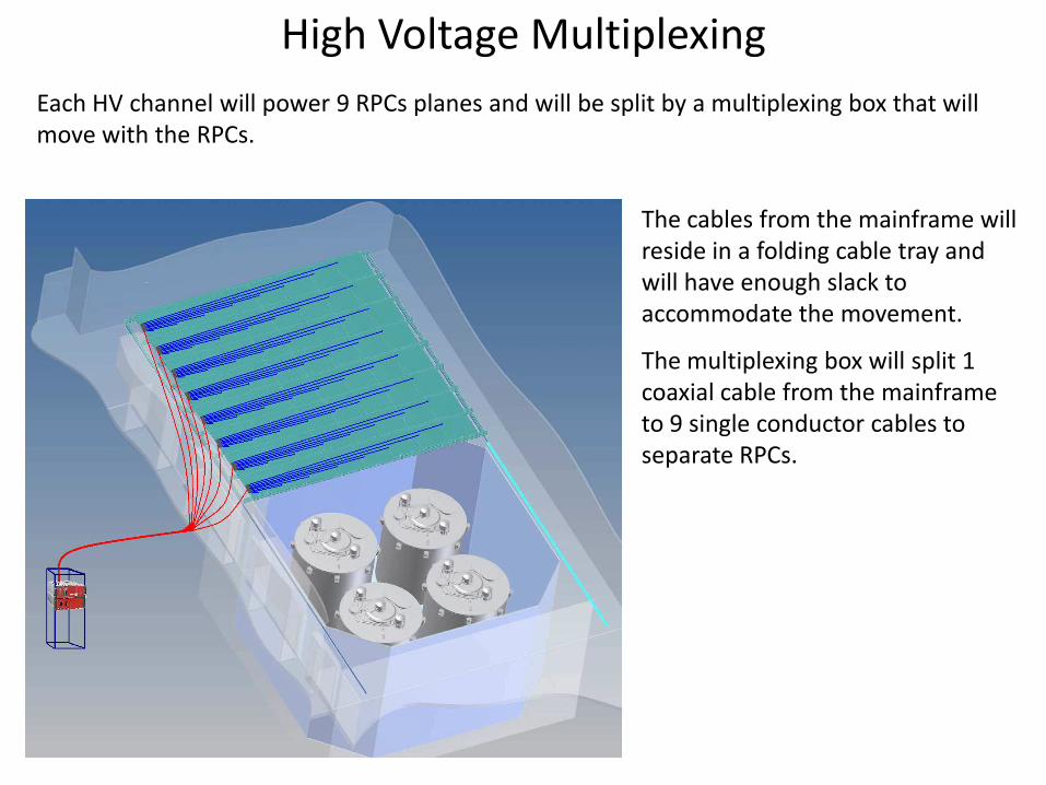
Each HV channel will power 9 RPCs planes and will be split by a multiplexing box that will move with the RPCs.
The cables from the mainframe will reside in a folding cable tray and will have enough slack to accommodate the movement.
The multiplexing box will split 1 coaxial cable from the mainframe to 9 single conductor cables to separate RPCs.

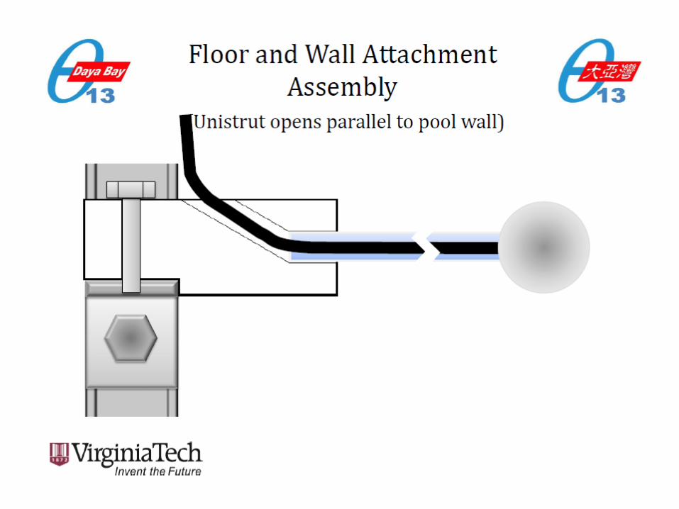
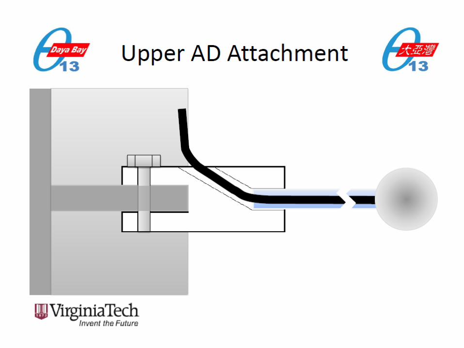
The RPC interface box will attach to the edge of the RPC module with four screws.
HV and ground connecting cables will pass through a slot in the Interface box matted to a slot in the RPC module box.
RPC Interface
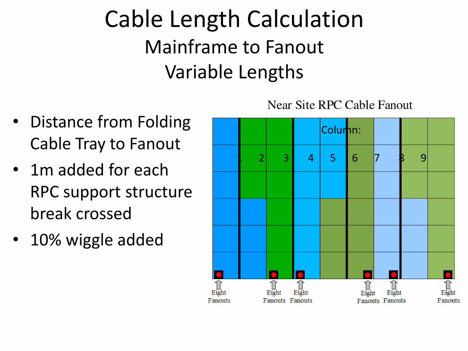
Cable Length CalculationMainframe to Fanout
Variable Lengths
• Distance from Folding Cable Tray to Fanout
• 1m added for each RPC support structure break crossed
• 10% wiggle added
Column:
1 2 3 4 5 6 7 8 9
ADsAD = anti-neutrino detector
At VT we work in the muon tagging system. This allows us to know when
a muon goes by our AD (which we care deeply about) Here is the brief
and dirty version of the Ads . . . .
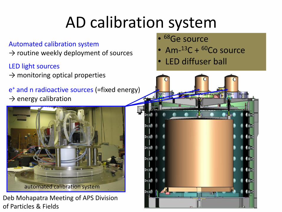
AD calibration system
automated calibration system
Automated calibration system→ routine weekly deployment of sources
LED light sources → monitoring optical properties
e+ and n radioactive sources (=fixed energy)→ energy calibration
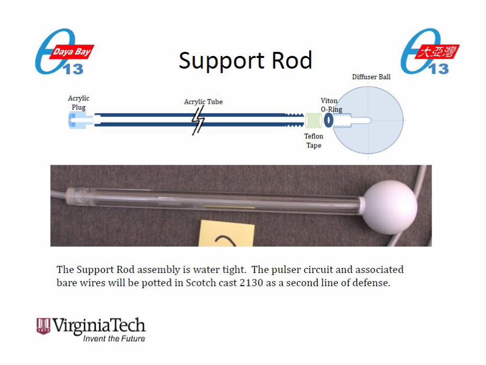
• 68Ge source• Am-13C + 60Co source• LED diffuser ball
Deb Mohapatra Meeting of APS Divisionof Particles & Fields
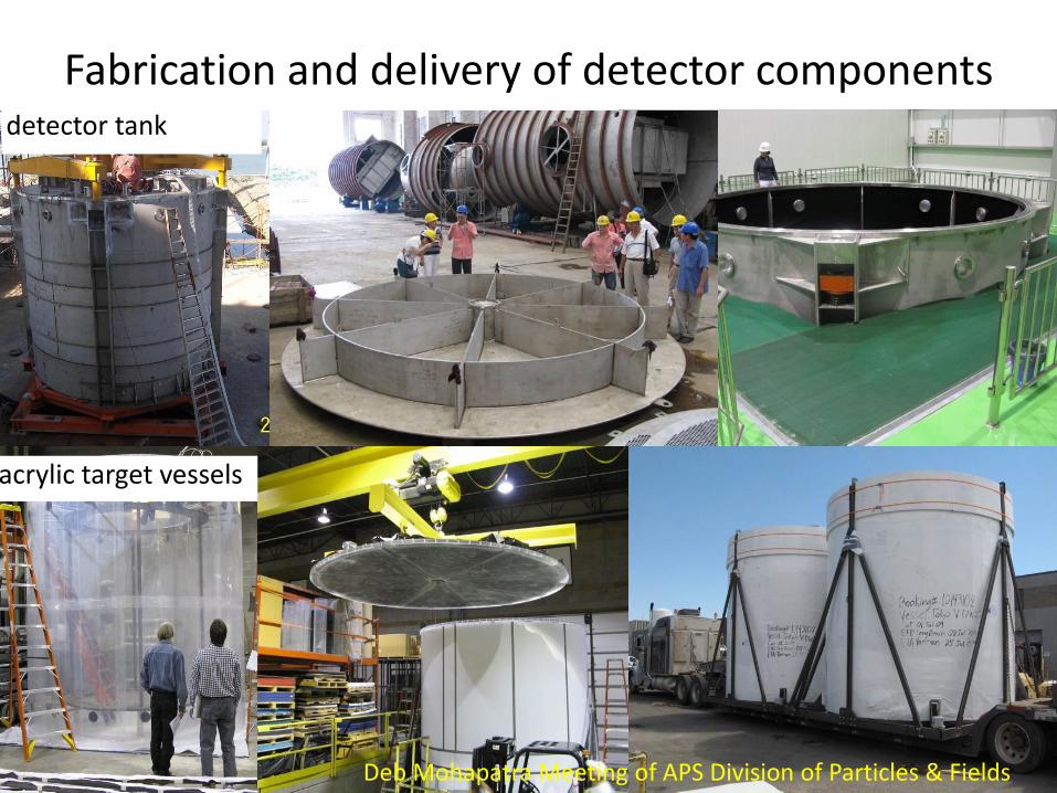
Fabrication and delivery of detector components
acrylic target vessels
detector tank
Deb Mohapatra Meeting of APS Division of Particles & Fields


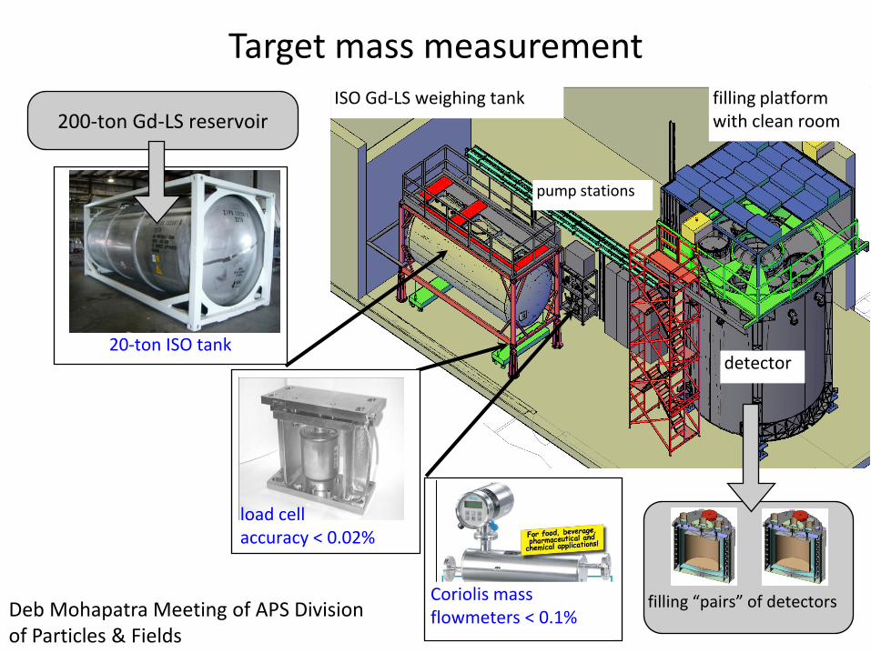
Target mass measurementfilling platform with clean room
ISO Gd-LS weighing tank
pump stations
detector
load cell accuracy < 0.02%
Coriolis mass flowmeters < 0.1%
200-ton Gd-LS reservoir
20-ton ISO tank
filling “pairs” of detectorsDeb Mohapatra Meeting of APS Divisionof Particles & Fields
The End
• Do you understand it all now?
• I doubt it, it took me a while and I still don’t call myself an expert.
• Questions?!!??!!?