Embed Size (px)
Citation preview

i
An Interactive Qualifying Project by Mert Can Erad, Aras Nehir Keskin, Siddhant Mohan, Abhishek Nalam, Matthew Shanck, Vivek Vishwakarma
C o l l a b o r a t i o n o f W o r c e s t e r P o l y t e c h n i c I n s t i t u t e a n d
I n d i a n I n s t i t u t e o f T e c h n o l o g y M a n d i 1 7 / 1 0 / 2 0 1 3
Day-Lighting Mandi District
i
Abstract
Homes in Mandi, India are poorly lit during the daytime, and the residents are
forced to use electricity to illuminate interiors. The goal of our project is to improve the
lighting of these households through use of alternative day lighting solutions. We
researched the available day lighting technologies for various building types. Our
collaborative team of students from IIT Mandi and WPI surveyed local villages to
confirm the interest and need for our project. We then combined our knowledge of
interior lighting systems with our interview results to develop prototypes and
subsequently implemented them into select houses. Finally, after a trial period, we
solicited feedback from the residents of the implemented houses and made
recommendations for solving this problem worldwide.

ii
Executive Summary
Studies show that sun-lit environments make people 16% more productive in their academic and professional activities. Harnessing free and available sunlight as a resource has been underutilized with the advent of electrical lighting in homes and businesses in Mandi District in Himachal Pradesh, India. The district of Mandi has in its perimeter two dams that play significant roles in the production of electricity. The generation of electricity from hydropower is such that the district exports the energy to nearby states. Due to this energy production, the electricity prices are substantially subsidized for the residents of Mandi, giving the most freedom to choose electrical lighting in their homes and businesses. The emission of greenhouse gases (GHG) during the production and use of electricity around the world is the primary contributor to global warming. Global warming contributes to climate change, which has the potential to devastate parts of the world. Using natural lighting during the day can reduce reliance on this energy by a substantial amount: potentially up to 12 hours of electricity consumption per day. It is a step towards reducing habitual energy consumption, with an overall impact of reducing greenhouse gas emissions, in turn aiding the environment.
With the collaboration of three students from the Kamand campus of Indian Institute of Technology Mandi in India and three students from Worcester Polytechnic Institute from the US, we focused together on reducing this dispensable energy consumption during the daytime using the abundant sunlight, through the implementation of alternative day lighting systems for residential lighting. Ultimately, observing the local perception of having these alternative technologies in the residents’ homes helped us to understand the level of awareness we have raised in the community, which could be applicable to many other communities globally.
Methodology In order to meet our project goal, we developed the following set of objectives:
1. Identify local community interest and need for day-lighting technologies 2. Assess the physical infrastructure of the targeted residential buildings 3. Create an efficient prototype, and implement it into model structures 4. Observe and solicit the positive and negative feedback of the prototypes
Our stakeholders consisted of the rural and urban residents in Mandi. For our first objective, we conducted short and concise verbal door-to-door surveys on our targeted sample of households, in which we used the sample of convenience and snowball sampling to select participants. This required us to visit households from six different communities including Mandi Town and to ask our basic survey questions to gauge their interest on our project and assess their level of need. Our second objective required us to administer in-depth face-to-face interviews with local residents. During our interviews, we asked them about the standards for

iii
technological options they would be comfortable adopting. These standards included cost (their price range or budget for such a technology), amount of retrofitting construction they were willing to tolerate, basic cultural assessments (to determine sensitivity to local traditions), and general feedback about sunlight quality in their homes. We also presented some of the available options that could potentially work for their house to get their general thoughts and preferences about them. Finally, we collected quantitative data including roof dimensions of the houses, and photographically recorded them. A significant portion of our project preparation consisted of research on existing day-lighting technologies and strategies in order to better understand our options to solve the problem. We compiled and analyzed all of the data we gathered from our surveys, interviews and observations to combine and match it with this research to ultimately produce the most feasible, viable and structurally compatible prototypes. We retrofitted existing day-lighting designs by using CAD software, and tested them using existing and accessible resources in the region. Finally, we implemented the chosen solutions on five sample houses in order to achieve our last objective, which was to observe the positive and negative changes that occurred after the implementation of the prototype into the houses. The social impact was inevitably the most important part of our 7-week journey. Recording the changes in the residents’ daily routines helped us evaluate the success of our prototypes, understand further and prove the significance of our project, record the people’s opinions about the prototypes and ultimately we raised awareness within a set of communities about the problem of unnecessary electricity use for lighting during the day.
Findings and Analysis For our first objective, the initial surveys were orchestrated in five different rural communities and Mandi Town. Out of a total of 30 houses surveyed, 20 of them gave a positive interest in our project and were interested in participating in a further interview process. By analyzing our survey data, we found that urban residents depend more on electricity use for day lighting in their daily lives than rural households. Contrary to our findings about dependency on electricity in urban and rural areas, rural residents were more interested in participating in our project compared to urban residents: only 40% positive interest in urban areas compared to an 80% interest in rural areas. Regardless of the sizes, every house we surveyed had at least one room with insufficient lighting. 18 out of the 30 houses surveyed stated that they use electricity during the day for lighting purposes. According to the data we have gathered from our target group, the average monthly electricity cost of the households in Mandi district is Rs. 438. This amount is equivalent to $7.1 according to the currency of 8th of October 2013.

iv
Out of 30 houses, noting that some houses had different types of roofs for different sections of the house, 21 had slate roofs, 5 had tin roofs and 9 had concrete roofs. Our second objective required us to revisit the households that gave positive feedback to our interest surveys. We interviewed 16 houses from four different communities, assessing the physical infrastructure of the roofs and details about the residents’ daily routines. We asked how they used their rooms, presented photographs of the existing day-lighting solutions with pros and cons and finally asked them to give their feedback on the solutions. Throughout our interviews, we simultaneously evaluated the feasibility of the prototype implementations. Although we interviewed concrete slab houses, early in the process we narrowed our target to houses with slate or tin roofs. The rigid and durable structure of concrete proved difficult to penetrate for retrofitting our prototype, and so we decided to exclude homes with this material from our implementation process. The technical part of the interview questions slightly varied according to whether the roof was tin or slate. Out of 16 participating houses, ten had slate roof structure, five had concrete, and one had a tin roof. Slate being the most prevalent roof type, our infrastructure analysis and design process mostly focused on these houses.
In most of the slate houses, the rooms included a ceiling that was built with a single layer of plywood. In the ceiling layer, were rectangular openings leading to the attic. We found out that these openings were commonly used for ventilation purposes for the cooking fumes as well as being used to access the attic layer for storage use. Simply replacing one or two slates with our prototypes would allow access to the interior of the house, which was our goal. During our interviews, we took several dimensions (1, 2) in order to build our prototype accordingly, which is shown below.
Figure A: A rough sketch of the slate-roof house structure and dimensions

v
From a social standpoint, we found out that the rural areas were more welcoming and enthusiastic about our visits. We were surprised to find that women in the villages seemed to lack understanding of the day lighting solutions we presented to them; they simply could not visualize the prototypes implemented into their homes. A positive finding was that the close community of the rural residents helped us execute our snowball sampling and raise awareness of the problem through “word of mouth”.
In terms of the prototype design, we found that people in the rural areas who lived in slate and tin roofed houses were more open to the idea of solar bottle bulbs. A solar bottle bulb, a 2L PET bottle filled with water and bleach, is fitted into a base that is implemented on a roof allowing the sunlight received from the outside
to transmit inside the house. The unique physical property of water allows the light to diffuse in the bottle, resulting in a light source equivalent to a 50W light bulb (see figure B, right). Generally, the main factors in the villagers’ decision towards the solar bottle bulb were whether the solution had easy maintenance and low cost. In the urban setting, we saw that residents seemed to find the hybrid lighting systems using fiber optic cables the best solution for their concrete slab houses, regardless of the cost.
In sum, the analyses of our findings helped us to understand that the most feasible day lighting solution for slate roof structured houses is a retrofitted design of the solar bottle bulb. By using the mobility of the slate tiles to our advantage, we came up with a simple design to satisfy the community needs for day lighting. As for the tin house, the most feasible and popular options were the solar bottle bulb and a crude configuration of a skylight.
We chose five houses for implementation, according to the households’ level of need and interest, as well as the logistical accessibility of the roof itself. We also tried to choose a variety of structures to work with, in order to see the differences in their feedback after the implementation. We chose one tin and four slate roofed houses for as our implementation samples. By designing our retrofit and working on constructing our prototypes in the Mechanical Engineering lab, we implemented one solar bottle bulb on a slate roof; three retrofitted solar bottle bulbs on slate roofs and a skylight on a tin roof.
Our retrofitted design, that we called “solar bottle cone”, was a 45.72cm by 91.44cm (1.5 ft. by 3 ft.) soft tin sheet rolled around the solar bottle in the shape of an upside down cone in order to focus the sunlight (see figure C, below). This design
Figure B: Solar bottle bulb prototype (Photo credit: Nehir Keskin)

vi
allowed us to transmit the sunlight directly into the room without it dispersing in the unused attic (see figure A). Lastly, we cut out a rectangular piece from the tin roof and implemented a rectangular transparent plastic sheet above it; allowing the system to serve as a skylight.
With help from some of the residents, we implemented our prototypes. Our initial observations after the implementations were that the prototypes were physically successful in transferring sunlight indoors. Even on a cloudy day, the prototype was transmitting a noticeable amount of sunlight. We gave the residents a one-week day trial period to experience the changes of the prototypes in their daily routines.
Our observations indicated that all five of our implemented households were happy with the implementation. In the short time frame as one-week, they had significantly reduced the use of their light bulbs for their interior lighting. Even though the slate roofed houses stated that the prototype worked efficiently only while in contact with direct sunlight, the difference it made was very noticeable.
In conclusion, throughout the duration of our project, we strived to make our prototypes an “appropriate technology” that would address an identifiable need in the communities. From a social standpoint, our project correlated with the needs and habits of the subjected residents. Our goal was for the outcome of this project to be a baseline for a broader spectrum of opportunity. Although this project was conducted in and around a small city in India, it can be a global model in terms of understanding the social outcomes of the implemented day lighting technologies.
Figure C: Solar bottle cone (Photo credit: Nehir Keskin)

vii
Acknowledgements
We would like to thank our sponsor Prof. Bharat Singh Rajpurohit for his supervision on
our project. Special thanks go to Indian Institute of Technology Mandi, Kamand Campus
for providing us a comfortable stay while conducting our project and providing us the
essential resources while designing and building our prototype.
An additional appreciation goes to Prof. Arti Kashyap for her enthusiasm and support to
our project. We would also like to thank everyone who helped us with our prototypes in
the Mechanical Engineering lab on the Kamand Campus, especially Prof. Rajeev Kumar
and R. S. Raghab.
Furthermore, we would like to state that this project contains important views, opinions
and input of numerous people from the Mandi area, Indian Institute of Technology
Mandi, and Worcester Polytechnic Institute. This includes the people we have gathered
data from during our project, our fellow WPI classmates, IIT students, and professionals.
Also, we would like to mention the great help of our WPI librarian Rebecca Ziino. We
could not have completed our project without the help and support of these people.
Finally, we would like to thank our project advisor, Ingrid Shockey for her excellent
guidance throughout the duration of our project.

viii
Addendum
Our project was featured in the Northern Indian newspaper Tribune. The article
describes the start to our project goal and the idea of our team bringing the solar bottle
bulbs to life in Mandi. The photograph in the article includes our team, our project
advisor Ingrid Shockey, and project sponsor, Bharat Singh Rajpurohit. The article is
dated September 22, 2013. During our project presentation on the 16th of October,
several NGO’s showed interest in our project and expressed that they would want to
take our project further. The next day, our team also met with the Mandi Deputy
Commissioner and presented the project. The D.C. was very interested in our project
and how simple our solutions were, along with them being so cost efficient.
Figure 1: Newspaper article from Tribune (Left to right: Vivek Vishwakarma, Matt Shanck, Aras Nehir Keskin,
Siddhant Mohan, Ingrid Shockey, Mert Can Erad, Abhishek Nalam, Bharat Singh Rajpurohit)

ix
Table of Contents
Abstract ........................................................................................................................................... i
Executive Summary ..................................................................................................................... ii
Acknowledgements .................................................................................................................. vii
Addendum ................................................................................................................................. viii
Chapter 1. Introduction ............................................................................................................... 1
Chapter 2. Literature Review ..................................................................................................... 3
2.1 Site Description ................................................................................................................................ 3
2.2 Energy Choices and Climate Change ............................................................................................ 8
2.3 Benefits of Day Lighting .................................................................................................................. 9
2.4.1 Appropriate Technology .................................................................................................................. 11
2.4.2 Manufactured Solutions .................................................................................................................. 14
2.5 Case Studies in Daytime Illumination ....................................................................................... 19
2.5.1 Illumination in Group Shelters ....................................................................................................... 19
2.6.2 Pyramid Shape Skylight over Vault Roof Mud-house in New Delhi ................................... 21
2.6.3 North Carolina Museum of Art ...................................................................................................... 22
2.7. Summary ....................................................................................................................................... 23
Chapter 3. Methodology .......................................................................................................... 25
3.1 Objective 1 ..................................................................................................................................... 25
3.2 Objective 2 ..................................................................................................................................... 26
3.3 Objective 3 ..................................................................................................................................... 27
3.4 Objective 4 ..................................................................................................................................... 28
Chapter 4. Findings and Analysis ............................................................................................ 30
Part 1: Findings .................................................................................................................................... 30
4.1 Objective 1: Identify local community interest and need for day-lighting technologies 30
4.2 Objective 2: Assess the physical infrastructure of the targeted residential buildings .... 36

x
4.2.1 Slate Roofs ............................................................................................................................................ 37
4.2.2 Tin Roofs................................................................................................................................................ 40
4.2.3 Concrete Slab Roofs .......................................................................................................................... 41
Part 2: Discussion ................................................................................................................................ 43
Part 3: Prototype Design and Implementation .............................................................................. 45
Step 1: Prototype Design ............................................................................................................................ 45
Step 2: Prototype Implementation.......................................................................................................... 50
Part 4: Observations of Implementation ........................................................................................ 53
Chapter 5. Results and Conclusion ......................................................................................... 55
Part 1: Results & Recommendations ............................................................................................... 55
Part 2: Conclusion ............................................................................................................................... 62
Bibliography ............................................................................................................................... 64
Appendix A: Sample Survey Questions ........................................................................................... 68
Appendix B: Additional Data ............................................................................................................. 69
Appendix C: Photographic Journal: Field Work and Implementation ....................................... 75
Appendix D: Timeline ......................................................................................................................... 87
Appendix E: Presentation Poster ..................................................................................................... 88

xi
Table of Figures
Figure 1: Newspaper article from Tribune (Left to right: Vivek Vishwakarma, Matt
Shanck, Aras Nehir Keskin, Siddhant Mohan, Ingrid Shockey, Mert Can Erad, Abhishek
Nalam, Bharat Singh Rajpurohit) ...................................................................................................... viii
Figure 2: Map of Mandi (District Mandi, 2001) ............................................................................... 3
Figure 3: Photo of a close by village, Nehri (Photo credit: Matt Shanck, 2013)..................... 4
Figure 4: IIT Kamand (Center of photo) (Photo credit: Matt Shanck, 2013) ........................... 5
Figure 5: Scene from Mandi Town (Photo credit: Jan Keleher, 2013) ...................................... 6
Figure 6: Table of air quality in Mandi Town (District Mandi, 2013) ......................................... 7
Figure 7: Different roof types in Mandi District (Photo credit: Bharat Singh Rajpurohit,
2013) ............................................................................................................................................................. 7
Figure 8: Wavelengths of different light sources (Light Source Introduction, OMRC) ...... 10
Figure 9: Solar bottle bulb (Klaasen, 2011) .................................................................................... 14
Figure 10: Model of Solatube ............................................................................................................. 15
Figure 11: Model of a Solar Shelve (Toms Guide, 2013) ............................................................ 16
Figure 12: Parans solar lighting system diagram (Parans, 2013) ............................................. 18
Figure 13: Light admitting device (Smith, 1963) ........................................................................... 20
Figure 14: Dome rooms in IIT- Delhi (Chel et al, 2009) ............................................................... 21
Figure 15: Surveying rural residents of Fadle village (Photo credit: Mert Can Erad, 2013)
..................................................................................................................................................................... 31
Figure 16: A rural house with a slate roof structure (Photo credit: Mert Can Erad, 2013)
..................................................................................................................................................................... 31
Figure 17: Raw survey data ................................................................................................................. 32
Figure 18: Urban interest chart ......................................................................................................... 33
Figure 19: Rural interest chart ........................................................................................................... 33
Figure 20: Image from a kitchen using electricity for lighting during the daytime (Photo
credit: Nehir Keskin, 2013) .................................................................................................................. 35
Figure 21: Chart of roof type quantities interviewed ................................................................. 37

xii
Figure 22: Terrace structure of the slate tiles (Photo credit: Mert Can Erad, 2013) ......... 38
Figure 23: Rough diagram of slate house dimensions ................................................................ 39
Figure 24: Deepak Kumal's "D.I.Y." day lighting system (Photo credit: Mert Can Erad,
2013) .......................................................................................................................................................... 40
Figure 25: Tin roofed house in Nehri Village (Photo credit: Nehir Keskin, 2013) .............. 41
Figure 26: Electricity-lit room during the daytime, Nehri Village (Photo credit: Nehir
Keskin, 2013) ........................................................................................................................................... 42
Figure 27: Women in Nehri Village - from various different households, all together .... 44
Figure 28: Slate house with ceiling opening - light distribution into the attic..................... 47
Figure 29: Solar bottle cone (Photo credit: Nehir Keskin, 2013) ............................................. 48
Figure 30: The house with no ceiling - slate structure (Photo credit: Mert Can Erad, 2013)
........................................................................................................................................... 48
Figure 31: Solar bottle bulb with a flat base sheet (Photo credit: Nehir Keskin, 2013) .... 49
Figure 32: Solar bottle bulb implemented on a roof. The nail is not visible because the
upper two slates are covering it. (Photo credit: Siddhant Mohan, 2013) ............................ 51
Figure 33: Photograph of the crude skylight prototype (Photo credit: Mert Can Erad,
2013) .......................................................................................................................................................... 52
Figure 34: Director's house interior design (Photo credit: Matt Shanck, 2013) ................. 56
Figure 35: Fadle Village House #1 [with no ceiling] kitchen (Photo credit: Nehir Keskin,
2013) .......................................................................................................................................................... 57
Figure 36: Fadle Village House #1 kitchen, from different angle (Photo credit: Nehir
Keskin, 2013) ........................................................................................................................................... 57
Figure 37: Fadle Village house #2 living room (Photo credit: Nehir Keskin, 2013) ............ 58
Figure 38: Roprigad Village house #1 kitchen (Photo credit: Vivek Vishwakarma, 2013) 59
Figure 39: Roprigad Village house #2 kitchen (Photo credit: Vivek Vishwakarma, 2013) 60
Figure 40: Nehri Village tin roofed house (Photo credit: Nehir Keskin, 2013) .................... 62

Introduction
1
Chapter 1. Introduction
Light produced by the sun approaches the earth as direct sunlight, reflective
sunlight (from surfaces), and skylight (the natural visible light of the sky, i.e. the light
diffused from the clouds) (Steffy, 2002). Harnessing that free and available resource has
been underutilized with the advent of electrical lighting in homes and businesses. At
the same time, studies show that people who work in a sun-lit environment are 16%
more productive in their academic and professional activities (WWF, 2011). Sunlight
itself has many positive and important effects on the human body such as enabling
access to vitamin D. Many would agree that homes which have good access sunlight are
often seen as more peaceful, productive, and a more “natural” environment in every
sense of the word. Finally, using direct sunlight to illuminate structures compared to
electricity-generated artificial lighting is beneficial economically and environmentally.
Given the abundance of free lighting, it is surprising to see that the design of residential
and commercial structures often ignores this capacity of the sun.
The district of Mandi, India, has in its perimeter two dams that play significant
roles in the production of electricity. The generation of electricity from hydropower is
such that the district exports the energy to nearby states. Due to this energy production,
the electricity prices are substantially subsidized for the residents of Mandi, giving most
the freedom to choose electrical lighting in their homes and businesses. Furthermore,
recent trends in local construction design and habits have moved residents towards
these low-cost artificial sources. However, the construction of hydropower dams has
other consequences. They damage the surrounding environment and displace both
communities and species in the ecosystem. According to the Hill Post, two more dams
are to be built within the next couple of years.
On a global scale, the emission of greenhouse gases (GHG) during the production
and use of electricity around the world is the primary contributor to global warming.
Global warming contributes to climate change, which has the potential to devastate

Introduction
2
parts of the world. Using natural sun lighting during the day is a step towards reducing
habitual energy consumption, with an overall impact of reducing greenhouse gas
emissions, in turn aiding the environment (Graham & Ebrary Academic, 2010). Using
daylight for interior lighting can reduce reliance on electricity by a substantial amount:
potentially up to 12 hours of electricity consumption per day.
This project is the work of collaboration between three students from the Indian
Institute of Technology, Mandi and three students from Worcester Polytechnic Institute,
in the U.S. We focused on reducing this dispensable energy consumption during the
daytime, using the abundant sunlight via simple alternative day lighting options for
residential lighting. Although our project can be applicable to residential buildings
globally, the focal point of our test site was the district of Mandi, specifically the
Kamand region, which is located in the state of Himachal Pradesh in the northwest of
India. Residential buildings located in the rural and urban areas in the district are the
subjects for our pilot project.
The goal was to identify and mitigate the inefficiencies of daytime lighting and
energy use through utilizing simple technologies for daytime lighting, and ultimately to
observe and record the changes in the residents’ lifestyles and perceptions. In order to
meet this goal, our objectives were to identify local community interest and need for
day-lighting technologies, assess the physical infrastructure of the targeted residential
buildings, create an efficient physical solution or design and implement it into several of
the subjected samples, and observe the positive and negative outcomes of the
implementation on the participating households.

Literature Review
3
Chapter 2. Literature Review
In this chapter, we present background information on Mandi District and
discuss the global context and significance of our project. We elaborate on the concept
of appropriate technology, and then describe the existing day lighting technologies and
prototypes that use direct sunlight for interior illumination in residential buildings. We
conclude this chapter with assessments of three case studies related to our project.
2.1 Site Description
To understand the setting and the context for this project, we reviewed the
essential landscape of the region. Mandi is almost at the geographical center of
Himachal Pradesh, lying along the left bank of the river Beas in the foothills of the
Himalayan Mountain Range (see Figure 2, below).
Figure 2: Map of Mandi (District Mandi, 2001)

Literature Review
4
According to the 2011 Census, Mandi District has a population of almost one million,
and the city itself is a medium sized community with a population of 60,982 residents.
The climate is typical of the region, with hot and rainy summers, and mild winters
(Commissioner, 2011b).
The IIT Mandi, Kamand campus is located 14km from Mandi Town. The Kamand
region is mainly covered in farmland used for grazing animals and for cultivating crops.
There are many small villages separated by kilometers of winding roads along the
mountainside. The villages are constructed in the valley or into the mountain (see
figures 3 and 4, below).
Figure 3: Photo of a close by village, Nehri (Photo credit: Matt Shanck, 2013)
Literature Review
5
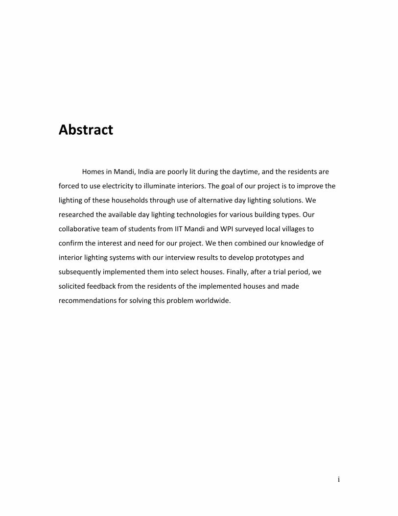
Figure 4: IIT Kamand (Center of photo) (Photo credit: Matt Shanck, 2013)
This type of environment is well suited for raising crops and livestock, and so
agriculture is the most prominent occupation in Mandi, totaling 79% of the economy
(Sarkar, 2011). However, this does not mean that there is not a busy commercial center
in the city. Mandi Town is full of small shops and food stands, as shown below in figure
5.

Literature Review
6
Figure 5: Scene from Mandi Town (Photo credit: Jan Keleher, 2013)
The unique geology and climate of Himachal Pradesh also means that the region
is fortunate to be a major supplier of energy from hydropower, but it can also be argued
that the overall sustainability of reliance on hydropower raises some questions. One
issue includes considering the hydropower dams’ impact on ecosystem as a
consequence for the local residents (WWF, 2013). An impressive 94.8% of the houses in
the state are electrified compared to the national average of 55.9%. The energy
consumption for various activities such as cooking, heating and lighting in the state of
Himachal Pradesh is the highest in northern India (Aggarwal & Chandel, 2010). Cities
that are located in valley-like settings often have a problem with air pollution that is
trapped by the surrounding terrain. The residents of Mandi keep a close watch on their
air quality, so much so that there is a chart displaying it on the homepage of the official
Mandi website (see figure 6, below).
Literature Review
7
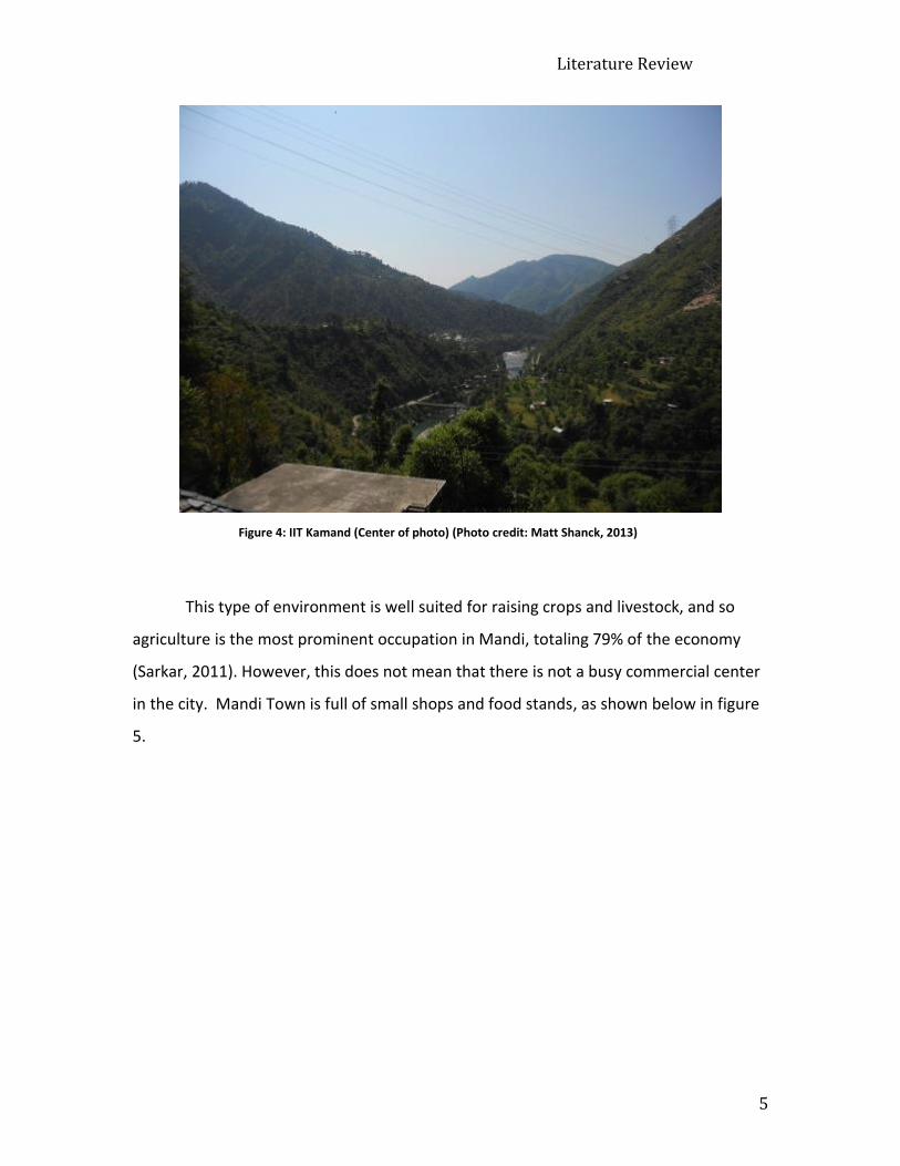
Air Quality in Mandi
24hrs.
Average
RSPM(µg/m3)
24 hrs.
Average
Lead(µg/m3)
24 hrs.
Average
Nickel(µg/m3)
24hrs.
Average
Arsenic
(µg/m3)
24hrs.
Average
SO2(µg/m3)
24 hrs.
Average
NOx (as
NO2)(µg/m3)
Standards
46.3 0.098 ND ND 2.0 4.5 All
Parameters
Within
Standards
Source: Air Quality Monitoring Carried out by The H.P. State Pollution Control Board
Figure 6: Table of air quality in Mandi Town (District Mandi, 2013)
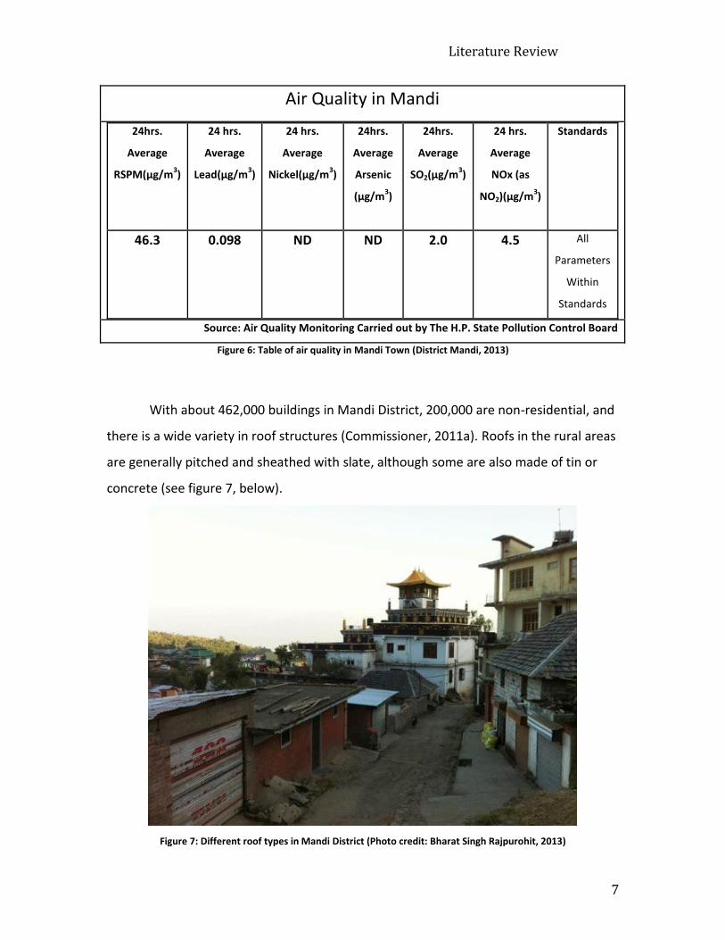
With about 462,000 buildings in Mandi District, 200,000 are non-residential, and
there is a wide variety in roof structures (Commissioner, 2011a). Roofs in the rural areas
are generally pitched and sheathed with slate, although some are also made of tin or
concrete (see figure 7, below).
Figure 7: Different roof types in Mandi District (Photo credit: Bharat Singh Rajpurohit, 2013)

Literature Review
8
Structural attributes in the urban Mandi Town include compact residential
buildings. These urban buildings are constructed close to one another, which creates
adjacent walls with no access to sunlight, leaving the roof the only way to access this
source. Since the district occupies an area with significant rise in elevation, the rural
houses are built on hilly terraces, which result in lack of sunlight to the back façades of
homes. These factors sometimes lead to three vertical walls being closed to the
outdoors, therefore disabling sunlight entrance into the interiors of houses.
This scenario creates a need for electricity consumption even during the
daytime. Especially when sunlight is potentially approachable, it is a very inefficient
system that results in excess electricity use, spending of money, and the indirect
emission of GHG’s, as mentioned before.
2.2 Energy Choices and Climate Change
While the local emission of GHGs may not be significant, the effort to change
behaviors on a small scale can bring benefits to global systems. Climate change is caused
by many factors, but the most prevalent one stems from increased CO2 emissions. The
buildup of carbon dioxide (CO2) in the atmosphere causes a process known as global
warming. Global warming heats the Earth’s atmosphere and, in turn, warms the planet
by a process known as the greenhouse effect. The greenhouse effect occurs from the
buildup of greenhouse gases such as carbon dioxide, methane, and ozone in the
atmosphere, which trap the sun’s rays as they bounce off of the earth’s surface (Graham
& Ebrary Academic, 2010). Although this is a naturally occurring process, it has spiraled
out of control due to the increasing use of fossil fuels that emit greenhouse gases.
Global warming will cause changes in temperature, weather, and seasons overall.
Changes in the aforementioned areas include the potential for catastrophic damage to
agriculture. Data from recent studies show that India is at the epicenter of risk due to
the widespread dependence on agriculture ("Climate Change in India: Forgotten
Threats, Forgotten Opportunities," 2010).
Literature Review
9
One of the easiest ways to reduce CO2 emissions is to reduce reliance on
electrical use, especially since much of this reliance is unnecessary or the result of poor
planning or design. Electricity that is produced in power plants is usually made by
burning coal to heat water into steam; which in turn spins a turbine that generates
electricity. In the case of hydropower, environmental impact concerns usually focus on
the secondary implications of dams and infrastructure, as well as the alteration of
natural water pathways that interfere with irrigation downstream. Two new 1300 MW
hydropower plants are planned to be built upstream in the Satluj valley within the next
few years (Makhaik, 2013).
The question becomes, “how do we simply reduce electricity use?”
Unfortunately, electricity use is habitual for daily activities such as powering lights in
shops and residential houses. Climate change is a global problem that could threaten
the daily lives of the human race if left unchecked.
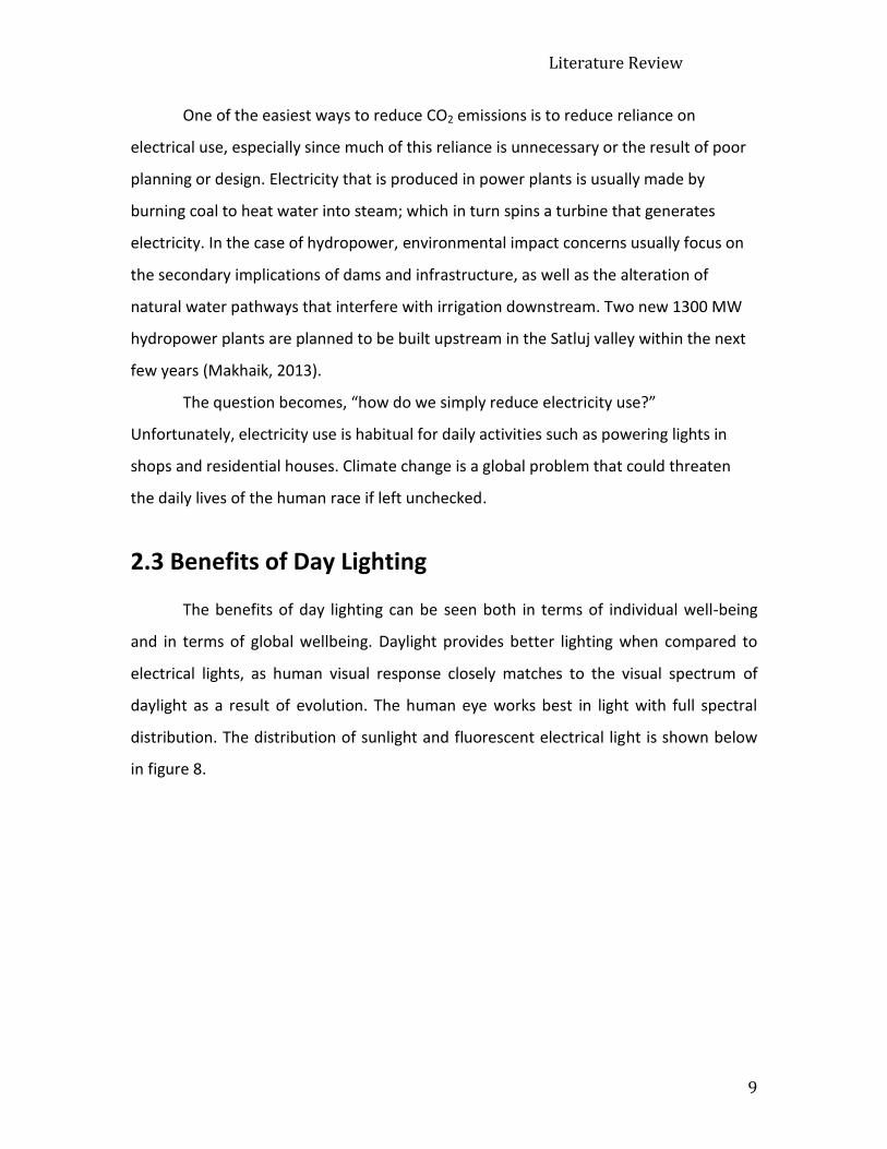
2.3 Benefits of Day Lighting
The benefits of day lighting can be seen both in terms of individual well-being
and in terms of global wellbeing. Daylight provides better lighting when compared to
electrical lights, as human visual response closely matches to the visual spectrum of
daylight as a result of evolution. The human eye works best in light with full spectral
distribution. The distribution of sunlight and fluorescent electrical light is shown below
in figure 8.

Literature Review
10
Figure 8: Wavelengths of different light sources (Light Source Introduction, OMRC)
Effects of daylight on humans can be both psychological and physical.
Psychological effects of daylight are associated with mood improvement, lower fatigue
and positive attitude. The physical effects of daylight such as production of vitamin D,
tanning, and reduced eye strain are either caused by light reaching the retina or on the
skin. According to Danzig, Lazarev and Sokolov, “physiological disorders may occur in
the human system if the human skin does not receive some exposure to solar radiation,
either direct or diffused, for long periods of time” (Edwards, & et. al., 2002).
At a macro level, community resilience is the ability to adapt and survive to
changes in the environment and economy (Andrew, 2012). In contrast, a community is
vulnerable if it is easily affected by changes around it. Using direct solar lighting can be
an effective way to improve community resilience and reduce vulnerability. Using low
impact technologies can alleviate electricity consumption; which alleviates GHG
emission, reducing global warming and therefore climate change ("Climate Change in
India: Forgotten Threats, Forgotten Opportunities," 2010).

Literature Review
11
2.4 Technology Descriptions and Applications
The sun’s rays have always been used for interior lighting. In present day, the
field of solar lighting uses many different technologies to bring natural daylight into the
interior of buildings. The technology ranges from fiber-optic systems to simply using
more windows. Some of the technologies are extensions of windows, but most involve
modifications to the roof. Direct solar lighting reduces energy waste in the production of
materials like light bulbs, eliminates greenhouse gas emissions, and can reduce cost.
Here we outline the attributes of technologies that are designed for low impact and high
performance.
2.4.1 Appropriate Technology
The concept of “Appropriate Technology (AT)” is a school of thought that is
widely accepted as incorporating technological strategy and technological application
together. Some of the defining characteristics include:
Small-scale
Sustainable
Labor-intensive
Energy efficient
Environmentally sound
Easily operated and maintained by the local community
(Hazeltine & Bull, 1999).
Another articulate source states that AT is “a concept, a social movement or
innovation strategy associated with a mode of technology-practice aimed at ensuring
that the technology is compatible with its psycho-social and biophysical context”(Hunt,
1994, p. 23).
The principal intent of AT is to utilize a community’s existing resources such as
local labor, natural resources, and community expertise in order to achieve the most
“appropriate” solution and development goals. An objective of AT is to help the
recipients become more self-reliant and resilient rather than more dependent and

Literature Review
12
vulnerable. The main idea of AT is to take into consideration the local ownership of the
change caused by the new project or idea to be implemented.
The change the community faces when a new concept or product is introduced,
is one of the most vital concepts to be considered when thinking of appropriate
technology. AT strives to be less disruptive to the social structure. It contains more local
resources than imported solutions, and it is essentially adaptable to the community’s
needs rather than being a “foreign object”. AT also anticipates the impact the change
will have beyond the hardware (Hazeltine & Bull, 1999).
Although sustainability is most commonly mentioned in conjunction with natural
resources, appropriate technology recommends that development is solely sustainable
if it can persevere after the “originator” leaves (Hazeltine & Bull, 1999). A simple
example for this can be explained with a Chinese proverb: “Give a man a fish and you
will feed him for a day, teach a man how to fish and you feed him for a lifetime”
(Anonymous, 2013). Collaborative design and local maintenance to continue the
implementation is one of the main milestones in an appropriate technological project.
A recent high-profile example of the “solar bottle bulbs” is by definition an
appropriate technology that was initially pioneered in Manila, Philippines. The project
encompasses most of the ideological criteria of an appropriate technology such as
promoting self-reliance, labor intensity, easy adaptability to community, environmental
efficiency, being small-scaled, localized, and most importantly sustainability. The
concept was created by Brazilian Alfredo Moser in collaboration with Illac Diaz, a
Massachusetts Institute of Technology graduate and the founder of MyShelter
Foundation. The main objective of the idea was to use the model for poorly lit
residential buildings, more commonly in slum structures, to reduce the electricity use
during the daytime and to help light up people’s lives in a literal sense (Fiedler, 2013).

Literature Review
13
Solar Bottle Bulb
The model itself is a very simple system consisting of a standard 2 L PET bottle,
galvanized iron corrugated/flat sheet, water, bleach and epoxy. Moser explains the
reason behind the bleach in a recent interview: "Add two capfuls of bleach to protect
the water so it doesn't turn green [with algae]. The cleaner the bottle, the better"
(Zobel, 2013). First, a circle with the same circumference as the PET bottle’s top one-
third cross sectional circumference is drawn on the galvanized corrugated iron sheet.
Secondly, a smaller circle with a circumference of 1 cm less is drawn inside of it and cut
out. The remaining 1 cm difference is cut perpendicularly into tabs and folded upwards
in order to give the bottle support. The connection point on the PET bottle is scratched
with the help of sandpaper in order to allow more holding for the epoxy or sealing
material. Then, the PET bottle is inserted and fitted into the previously prepared sheet.
Epoxy is applied where the bottle and sheet come together: bottom face of the sheet
and on the strips that are folded upwards, sticking the bottle and sheet together. The
bottle is filled with 10 ml (2 caps full) of chlorine or bleach and the rest with filtered
water. A circle with the same circumference is cut out of the roof the model will be
installed on and rubber sealant is applied around the hole. Then the model is inserted
and the edges of the sheet are sealed to the roof with rubber sealant in order to prevent
water leakage. Finally, a protective cap is fitted to the mouth of the bottle with epoxy to
prevent cracking due to the heat of the direct sunlight (see Appendix B for detailed
video). The amount of light the model provides the house can be compared to a 50-
Watt light bulb (Liwanag, 2012). The average lifespan of the solar light bulb is 4-5 years.
Figure 9 (below) shows a cross-section view, as well as the bulb in a room.

Literature Review
14
Figure 9: Solar bottle bulb (Klaasen, 2011)
MyShelter Foundation set into motion the “Liter of Light” project that has
currently reached out to about 30 countries such as Peru, Columbia, Bangladesh, and
recently to Mumbai and Hyderabad in India. The project installed over 200,000 solar
bottle bulbs, each costing a little over a dollar. The benefits of this project are immense.
From an environmental perspective, the estimated carbon footprint of the
manufacturing process of one light bulb is 0.45 kg CO2, and 0.77 kg CO2/kwh is the value
of a 50-Watt light bulb working for a full 14 hours (approximate daylight time) and
therefore one solar bottle bulb saves ~278 kg CO2 from getting emitted into the
environment. Today, grassroots entrepreneurs are taught the building process and how
to continue the project by using the existing simple materials that are easily reachable
within the community and this allows the project to be sustainable (Anonymous, 2012).
In conclusion, a compact solution such as the solar bottle bulb can impact a
community tremendously. Appropriate technologies have the capability to be able to
uplift communities economically, environmentally, and socially, providing a better
standard in living, and a positive response to climate altering behaviors.
2.4.2 Manufactured Solutions
Here we present some additional promising manufactured lighting options that
are currently available and in widespread use. These vary in complexity and in cost.

Literature Review
15
Solatube International®
Solatube International is the world leader company in manufacturing Tubular
Daylighting Device (TDD) systems that allows the entrance of direct sunlight into the
interior of residential and commercial buildings. The company was founded in 1990,
headquartered in Vista, California. The system consists of two main components: the
sunlight-capturing dome lens that is installed
on the roof of the building allowing the
absorption of direct sun rays, and the second
part: a multi-directional tube that will transport
the light from the dome lens into the interior of
a room. The tube has in it a multi-angled mirror
system that allows the sunlight to transport by
reflection (see Figure 10, right).
Installation is fairly easy, with a “Do It
Yourself” instruction manual that comes with
the product. The cost varies by the length of the pipe and the radius of the opening: a
10-inch diameter pipe system ranges from USD $255 to USD $290, whereas 14-inch
pipes range from USD $365 to USD $425. The length of the system also varies between
20-30 feet (additions are available) allowing the product to serve different types and
sizes of buildings. The area lit by the system also varies according to the diameter, but
the average range is 200-500 ft2 (International, 2010). Being environmentally sound,
versatile, easily installable and maintainable are some of the qualities that make this
product efficient. A disadvantage of the system is the fact that it is hard for residents to
maintain due to the lack of accessibility to specific parts for the system around the
world.
Solar Shelves
Although there are various designs for Solar Shelves, the main idea uses an
overhanging mirror system in conjunction with a window that gets direct sunlight during
the daytime (see figure 11, below).
Figure 10: Model of Solatube
(Housetrends, 2013)

Literature Review
16
Figure 11: Model of a Solar Shelve (Toms Guide, 2013)
The design is essentially made up of reflective film panels or mirrors that are
attached to the window glass from the exterior to the interior of the building, therefore
reflecting the incoming sun rays towards the ceiling, which is coated with a reflective
color to maximize light reflection of the room. Some designs are customized by adding a
curvature to the reflective film, in order to provide for different angles of the sun during
the day. The profile is designed to generally spread the sunlight within 12°-15° angle
range. Light shelves can extend the sunlight to about 6-8 m. Some designs have
additional reflectors opposing them in order to reach maximum efficiency in capturing
sunlight (Almusaed, 2011; Beltran, Lee, Papmichael, & Selkowitz, 2008; Mayhoub &
Carter, 2010).
The benefits of this model include: the reduction of glare that is generated by
direct sunlight diffusion into the room; the fact that it is environmentally sound; high
sustainability if installed correctly, ease of installation, relative cost efficiency compared
to available technologies in the market and innovation (Almusaed, 2011). This
technology is not as advantageous as others, because it is a relatively new design and it
is only as efficient as the amount of direct sunlight the window receives.

Literature Review
17
Skylights
Skylights are one of the oldest and most widely used day-lighting systems. A very
raw definition would be that they are essentially windows that are not located on the
sidewalls, but rather on the ceiling. There are many different types of skylights currently
in the market: domes, vaults, glazed roofs, flat ceiling applications and other
applications with translucent roofing materials being only a few of them. There are an
abundance of patents in the world today that lists various designs for skylights (Chel,
Tiwari, & Chandra, 2009).
The main objective of the system is to let sunlight directly into the building. A
requirement and perhaps a disadvantage of skylights would be that the room must be
on the very top floor of the commercial/residential building. Similar to the solar shelves,
skylights are also relatively more affordable than other technologies in the market. At
the same time glare, poor insulation in the wintertime, and leakage are among the
greatest challenges of this application (Blomberg, 2004; Eijadi, Abraham, Dekeyser, &
Hansen, 1901; Jensen, 1901; "Skylight design," 1995).
Hybrid Lighting Systems (HLS)
Hybrid lighting systems have been one of the most well-known and used
technologies in the 20th century. The system functionality is similar to an electric cable:
it transports sunlight through cables from the receiver to the transmitter. The system is
made up of three main parts: a sunlight receiver/collection system, sunlight
transportation system and a daylight output device. Although there are many types of
different hybrid systems in the market right now, they all share the same infrastructure
(Mayhoub & Carter, 2010). The receiver is generally made up of heliostats (parabolic
mirrors, Fresnel lenses, etc.) that allow the sunlight to concentrate to a specific point.
The transportation system is made up of optical fibers (fiber optic cables) that transport
the light into the output device also known as a luminaire, which is essentially an output
device that diffuses the daylight (Muhs, 2008; Tsangrassoulis et al., 2005).
There are different types of hybrid lighting systems: heliobus, arthelio, hybrid
solar lighting (HSL), universal fiber optics (UFO), solar canopy illumination system (SCIS)

Literature Review
18
and fiber optic lighting systems (Parans). These are essentially the same system with
different design components. The most commonly used system is the Parans system;
which is a Swiss patented hybrid lighting manufacturing company. The Parans receiver
system (SP3) has a smart light sensor that can detect the direction of the sun and has
the ability to rotate towards it for the maximum efficacy. Also, a special detection
system allows the users to feel the exterior weather via the luminaries. The fiber optic
cables have a diameter of 8mm and the length ranges from 5-20 m (Parans, 2013).
Hybrid lighting systems can transfer the light to rooms that are not close to the roof or
the sunny side of the buildings (see Figure 12, below).
Figure 12: Parans solar lighting system diagram (Parans, 2013)
Hybrid lighting systems have many benefits. The alleviation of “daylight glare” is
one of the greatest advantages along with having spatial benefits due to the
compactness of the fiber optic cables allowing minimal invasive installation procedures
on building structures. The fact that the cables can reach out to tens of meters of length
allows the system to be functional in multiple floored buildings. This function can
ultimately benefit rooms without any windows such as conference rooms; which are
generally situated in the center of buildings. Another great advantage is the filtration of
the non-visible radiation components; which reduces the necessity of cooling systems.

Literature Review
19
One drawback to this technology is its cost. HLS is the most expensive technology
overall mentioned in this report.
2.5 Case Studies in Daytime Illumination
We researched three projects on the application of different technologies in
different geographical locations, including one from 1963, indicating that people have
been looking for ways to use direct sunlight for illumination for a long time. These
different case studies are from the US and India that worked on a similar goal: to
improve interior lighting.
2.5.1 Illumination in Group Shelters
A prototype for illuminating a group of shelters during the daytime was
constructed by Sanders and Thomas Incorporated in Pottstown, Pennsylvania in March,
1963. The main function of the prototype was to use direct sunlight during the daytime
for lighting the interior of shelters for the Office of Civil Defense. The motive for this
prototype was to supply lighting during power cuts and to conserve fuel energy during
the day. Key factors for implementing the development of the prototype were to use,
“materials readily available” and for this device to, “be relatively simple to construct,
install and operate”(Smith, 1963, p.1).
First, they conducted experiments in a shelter to determine the optimum
amount of lighting required for human subjects to be able to perform tasks, such as
needle threading and reading. After determining the bare minimum lighting required in
shelters, they evaluated the possible sources of lighting by testing each source’s
efficiency. Ultimately, they tested several designs that used combustion, electrical,
natural and radioactive energies. For the purpose of our work, they also tested a
prototype that used direct sunlight for illumination called the “Light Admitting Device”
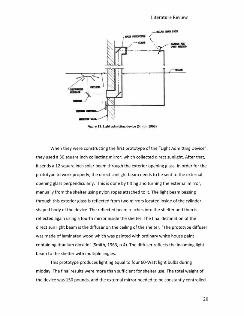
(Smith, 1963) (see Figure 13 below).
Literature Review
20
Figure 13: Light admitting device (Smith, 1963)
When they were constructing the first prototype of the “Light Admitting Device”,
they used a 30 square inch collecting mirror; which collected direct sunlight. After that,
it sends a 12 square inch solar beam through the exterior opening glass. In order for the
prototype to work properly, the direct sunlight beam needs to be sent to the external
opening glass perpendicularly. This is done by tilting and turning the external mirror,
manually from the shelter using nylon ropes attached to it. The light beam passing
through this exterior glass is reflected from two mirrors located inside of the cylinder-
shaped body of the device. The reflected beam reaches into the shelter and then is
reflected again using a fourth mirror inside the shelter. The final destination of the
direct sun light beam is the diffuser on the ceiling of the shelter. “The prototype diffuser
was made of laminated wood which was painted with ordinary white house paint
containing titanium dioxide” (Smith, 1963, p.4). The diffuser reflects the incoming light
beam to the shelter with multiple angles.
This prototype produces lighting equal to four 60-Watt light bulbs during
midday. The final results were more than sufficient for shelter use. The total weight of
the device was 150 pounds, and the external mirror needed to be constantly controlled

Literature Review
21
for optimum lighting, therefore this device is not practical to use. Compared to the
compact devices that we are using today, the “Light Admitting Device” had large
components. If we compare this prototype to Solatube, we can identify the similarities
between the two technologies. The “Light Admitting Device” operates with a similar
tubular structure and the use of mirrors. Solar pipes have the collecting mirrors and
diffusers implemented within the body; which makes them the next generation of the
“Light Admitting Device”.
2.6.2 Pyramid Shape Skylight over Vault Roof Mud-house in New Delhi
Using both experimental and theoretical data gathering and calculations, a
pyramid shape model of skylight efficiency and benefits are evaluated by a group of
professors from Centre for Energy Studies of Indian Institute of Technology in Delhi.
Three different sized mud houses were the subject of this research project: two being
small domes and the third a larger one. Small domes had the skylight installed 3m above
the ground and the big one had the skylight installed 7m above the ground level (see
Figure 14, below). The team also gathered data on the heat gained from the skylights
because one of the most important aspects of skylight models is to be able to prevent
overheating due to the heat gain from the sun.
Figure 14: Dome rooms in IIT- Delhi (Chel et al, 2009)

Literature Review
22
The team gathered data from the mud houses in mid-January and in mid-June.
They also gathered luminance level data throughout the year to make sure that skylights
supply enough lighting regardless of weather conditions. The results showed that
skylights saved a significant amount of energy by supplying a sufficient amount of
luminance level for office work. Their research also states that: “If 5% of the total
households in Delhi state are built with such mud-house with skylight arrangement,
then total annual lighting energy saving potential and annual mitigation of CO2 emission
will be approximately 146 million kW h/year and 0.23 million metric tons per year,
respectively” (Chel et al, 2009, p. 2518).
The prototypes showed the possible benefits of skylights for the local
community, and the report also indicated that, “the Indian government had planned to
adopt green rating for integrated habitat assessment for all new buildings. The authors
noted, “this will be mandatory for commercial buildings which consume 100 kW of
power or more in 1 hour” (Chel et al, 2009, p. 2518).
The research and calculations provided enough scientific data to show that the
pyramid shaped skylights provided enough energy during the day time regardless of the
sun’s position by refracting the direct sun light into the mud houses. They also note the
beneficial use of direct sunlight by calculating the possible savings of artificial electricity.
Overall, the project was successful and the data supports the theoretical position that
they calculated before starting the project. On the other hand, they did not consider the
social aspect of use of skylights, nor did they consider the cost of installing skylights to
residential and commercial buildings. The skylights used for this project is limited to the
shape of the domes. Approaching this project only scientifically with luminance level,
energy savings and environmental benefits makes their predictions about the practical
application of skylights in the local community less accurate.
2.6.3 North Carolina Museum of Art
A North Carolina Museum of Art project completed by Thomas Phifer & Partners
demonstrates the efficiency of natural daylight illumination. 362 skylights used in the
project light up an area of approximately 6000 square meters during daytime
Literature Review
23
("Solutions: Lighting," 2010). The biggest challenge they faced was keeping the direct
sunlight away from the interior of the museum to prevent overheating. They used a
special skylight design with 4 layers. As the direct sun light beam hits the external layer
of the skylight, it is diffracted and as it moves through the inner two layers of glass the
refracted sunlight gets directed towards the walls of the museum with further
diffraction. The last layer of the skylight is a fabric; which can be used to protect some of
the exhibits, such as textiles, from the sun light radiation.
They also used artificial lighting systems along with the skylights for perfecting
the luminance levels within the museum at all times. Using light sensors within the
museum allows a smooth transition as the sun sets or if a cloud covers the sun. These
sensors sense the decrease in luminance levels and activate the artificial lighting system.
Also, instead of switching the artificial lights on and off at once, the artificial lighting
system is adjusted by the sensors to keep the total luminance within the museum at a
constant level.
Overall, this project is successful as it shows how much power can be saved from
using skylights that operate in tandem with existing electrical systems. On the other
hand, special skylights with multiple layers for diffraction, use of light sensors, and
artificial light systems, with various levels of lighting, increased the cost of the total
project to 86 million US dollars. This is a very steep price and the project report does not
give any information about the payback time. This project demonstrates that even in
museums where lighting is very important, skylights can be used with a backup artificial
lighting system but the high cost makes this system only interesting from a theoretical
perspective.
2.7. Summary
The literature review revealed that there are many different models and
technologies about daylight illumination that exist in the world today. From models as
simple and compact as a PET bottle filled with water, to more complicated technologies
such as hybrid lighting systems, we have discovered that technology varies immensely.

Literature Review
24
Each of the solar lighting technologies we have mentioned above is applicable to
different types of buildings. Even so, the “key factors” as mentioned above apply
throughout: “materials readily available” and “being relatively simple to construct,
install and operate”. By keeping in mind the appropriate technology characteristics
mentioned previously, these two pivotal factors played a big role in conducting our
project throughout our time in Mandi.

Methodology
25
Chapter 3. Methodology
There are widespread inefficiencies in day-lighting options for rural and urban
residential buildings in Mandi. This leads residents to use electricity rather than natural
sunlight during the daytime; which, in turn, causes higher energy costs per capita and
harms the environment by wasting energy. Our goal was to reduce the inefficiency of
daytime lighting and energy use through the application of both affordable, easily
accessible and feasible solar day lighting systems, and to record the residents’
perceptions after their implementation. In order to meet our project goal, we developed
the following set of objectives:
Identify local community interest and need for day-lighting technologies
Assess the physical infrastructure of the targeted residential buildings
Create an efficient prototype, and implement it into model structures
Observe and solicit the positive and negative feedback of the prototypes
In this chapter we limn the social science strategies we used to conduct our
project.
3.1 Objective 1
Identify local community interest and need for day-lighting technologies
Our stakeholders consisted of the rural and urban residential structures in Mandi
District. Consequently, our sample was drawn from the residents of the targeted
structures. In order to meet our first objective, we identified prospective residential
houses in a sample of convenience.
Surveying is an efficient method to use if we are looking for answers to
straightforward questions (Berg & Lune, 2012). James K. Doyle also states in the IQP
Handbook that surveying is a good method to follow “…if simple factual information or
quantitative judgments are desired” (Doyle, 2004, p. 2). We conducted short and

Methodology
26
concise verbal door-to-door surveys among our targeted households. This required us to
visit a number of homes in seven different communities including Mandi Town in order
to ask our basic survey questions directly to a range of participants. We aimed to
determine the existence of inefficiencies in daytime lighting. This initial survey consisted
of a basic set of questions to simply get an idea of community-wide knowledge and
interest in the matter (see Appendix A for survey questions). This also helped us
intuitively gauge their interest in participating in a pilot study. We used snowball
sampling to add more households within our range of targeted samples. The surveys
were conducted on both urban and rural household residents.
During our surveying process (followed by interviewing), the IIT (Indian Institute
of Technology) teammates played a paramount role in communicating with the local
participants. They helped bridge the language gap by translating both parties to each
other, first-handedly.
3.2 Objective 2
Assess the physical infrastructure of the targeted residential buildings
This objective allowed us to inspect and evaluate the structural dimensions to
the energy requirements of residential buildings. We began with a detailed site
assessment of the targeted households, observing and documenting the dimensions and
layout of the homes. We collected data about the conditions of the site to help
determine essential physical properties of our lighting choices.
In order to meet this objective, we used targeted sampling to identify
participants. Our sample consisted of a small population of households in the area that
showed positive interest in our survey. We administered in-depth face-to-face
interviews with homeowners. During our interviews, we asked residents about the
standards for technological options they would be comfortable adopting. These
standards included cost (their price range or budget for such a technology), amount of
retrofitting construction they were willing to tolerate, basic cultural assessments (to

Methodology
27
determine sensitivity to local traditions), and general feedback about sunlight quality in
their homes. We also presented some of the available options that could potentially
work for their house to get their general thoughts on them. This method allowed us to
interact with the participants and assess the level of interest (Berg & Lune, 2012).
Throughout our project, we continued to evaluate potential technology
applications, including ideas such as sunlight concentration, duration, and path analysis
of the geographical area of interest. Using the technological and constructional
resources in the mechanical engineering lab at the IIT, as well as knowledgeable faculty,
staff, and students, we conducted prototype research pertinent to the physical
component of the project. We used visual documentation to support our analyses,
including photographs of the area and the interiors of the targeted houses.
3.3 Objective 3
Create an efficient prototype and implement it into the model structures
A significant portion of our project preparation consisted of research on existing
day-lighting technologies and strategies in order to better understand our options to
solve the problem. Researching alternative strategies consisted of assessing
“appropriate technologies” and shaping our project accordingly so that it ultimately
would be applicable not just in Mandi, but also globally.
Our research goal included forming a better understanding of the technical part
of the solution. This collaborative research with WPI and IIT teammates –combined with
the data collected in the project– helped us compare, assess and evaluate the most
feasible and appropriate technology solution for our targeted stakeholders in our
project. We compiled and analyzed all of the data we gathered from our surveys,
interviews and observations to combine and match it with the prior research that we
conducted previously, regarding the available day-lighting technologies.
We presented and pilot tested three of the most feasible day-lighting scenarios
for the targeted community. The prototypes were designed to meet the tenets of

Methodology
28
appropriate technology, including:
Most viable cost range according to the community
The factors of maintenance of the system
Standards, needs, and habits of the targeted participants
The structural compatibility of the design with the buildings
These guidelines provided us with a rubric, which allowed us to evaluate the day-lighting
technologies. By using our assessments and findings, we made best practice
recommendations about day-lighting technologies that met our targeted community’s
needs.
We created practical designs of the most feasible day-lighting systems by
synthesizing our research, interview data and findings. We gathered specimens from our
sample houses to aid us. We retrofitted existing day-lighting systems and tested them
using existing and accessible resources in the region. Finally, we implemented the
chosen solutions on five sample houses in order to achieve our last objective. The five
houses were selected based on their level of need for such systems and their
convenience in terms of location and simplicity of their construction.
3.4 Objective 4
Observe and solicit the positive and negative feedback of the prototypes
The social impact was inevitably a very important part of our 7-week journey.
Recording the changes in the residents’ daily routines helped us answer important
questions: Are the residents using less electricity for lighting the interior of their houses
during daytime? Are the residents spending more of their time inside their houses
during the daytime? Are the residents happy about the new changes? What kind of
positive or negative changes did the implementation of our prototypes make on the
residents’ daily routine? What are the residents’ opinions about the prototypes and did
their opinions change in any way after implementation? What are the weaknesses of
the prototypes?

Methodology
29
Along with these questions, we also delivered instructions about the prototype
construction and implementation. In order to meet this objective, we gave the residents
a one-week trial period to test the prototypes and adjust to the idea of their presence.
We then revisited them for the last time to solicit feedback on the outcome of the
solutions by conducting face-to-face interviews.

Findings & Analysis
30
Chapter 4. Findings and Analysis
This chapter will elaborate upon our findings during our fieldwork as well as the
analyses of these findings. The results include responses to the survey, interviews, as
well as the team assessment of existing resources and prototype designs. Since our four
objectives were set in progressive stages we present and analyze the results from each
step.
Part 1: Findings
Here we present the findings from Objectives 1 and 2.
4.1 Objective 1: Identify local community interest and need for day-lighting
technologies
The first step in achieving our goal was to conduct surveys to explore the interest
of the dwellers as well as the residential need for solutions. 30 surveys were
orchestrated in 5 different rural communities in the Kamand region, within a radius of
12km from IIT Kamand campus. The rural communities were villages of Nehri, Roprigad,
Fadle and two other communities close by to the IIT Kamand campus. Our urban setting
was central Mandi Town.
We started our surveys by visiting the households at villages of Nehri and Fadle.
Out of the 14 households surveyed, eight households were in Nehri Village and six were
in Fadle Village (see figure 15). We were pleasantly surprised by the hospitality of the
villagers and their interest in participating in our project.

Findings & Analysis
31
Figure 15: Surveying rural residents of Fadle village (Photo credit: Mert Can Erad, 2013)
Figure 16: A rural house with a slate roof structure (Photo credit: Mert Can Erad, 2013)

Findings & Analysis
32
We continued surveying in Mandi Town. Unlike the rural residents we surveyed,
people who live in the city were not as interested in participating. Consequently, we
were only able to survey 10 houses. During our fieldwork in urban areas, we found that
most of the houses had concrete slab roofs, unlike the rural houses where slate roofs
were predominant.
Therefore, we decided to focus the last six surveys on rural houses, because the
best roof types for implementation were slate and tin roofs. For these last surveys, we
traveled further away from campus, to get a variety in location. Most of these houses
were self-sustainable by the family members. Being self-sustaining, made these families
interact less with the outside world, thus they were skeptical towards our project and
even hesitant to talk to us.
Figure 17: Raw survey data

Findings & Analysis
33
We brought all the raw data from surveys together in one table, for the
convenience of the reader (see figure 17, above). Each horizontal row represents a
house, and the columns represent various survey questions. Our target group of houses
included households with different sizes
ranging from houses with only one room up to
houses with 12 rooms. Regardless of the size,
every house we surveyed had at least one room
with insufficient lighting. On a side note, in a
few cases, while we clearly thought there was a
lack of daylight in the rooms, the residents
stated the contrary. This finding led us to
question the idea that there is a universal
perception of abundant lighting, which we will
discuss in greater depth later.
Only 17% of the residents surveyed
were using an alternative to electricity as a lighting source, such as candles.
Furthermore, 80% of the residents who were using candles were also using electricity
during the daytime when electricity was
available. Power outages were not significant
enough to mention in the raw data. According
to our data, the average monthly electricity
cost of the households was Rs. 438.
Additionally, most of the houses use other
electrical appliances such as fans, televisions,
refrigerators, and heaters. The use of these
appliances, especially electrical heaters during
the winter, is responsible for the largest
portion of the residents’ monthly electricity
bills. Moreover, when we further analyze the data on bill costs, we found that average
Figure 19: Rural interest chart
Figure 18: Urban interest chart

Findings & Analysis
34
electricity cost for rural residents was Rs. 379, whereas for urban residents it was Rs.
558.
Contrary to our findings about dependency on electricity in urban and rural
areas, rural residents were more interested in participating in our project compared to
urban residents. In total, 67% of the participants were interested in participating in our
project further with the interview process. Only 40% of urban residents showed a
positive response towards participating in our project, whereas in the rural areas that
number doubled. Consequently, majority of the urban respondents chose not to
participate. Having 80% positive feedback from the rural areas along with suggestions of
our sponsor, we decided to focus on rural households for implementing our prototypes.
Although this was the case, we continued with our original plan to interview the urban
Mandi Town in order to get more extensive data for further analysis.
Now we will elaborate on a specific challenge we have faced during our
surveying process, along with some observations that we find significant.
Perception of light
Physics defines illuminance as the density of photons on a surface per unit area.
It is basically the density of light that we perceive to be present in a specific area or
room. Even though modern physics is easily able to define such a concept, the human
eye can be subjective. This subjectivity can depend on simply the level of illuminance we
have come to be accustomed to in our daily lives.
As a team, one of the significant challenges we faced during the surveying
process was the fact that some of the residents did not see the “lack of light” being a
problem in their houses. Despite the fact that they did not think the rooms were dark,
they stated that they use electricity in order to use the rooms. Ultimately, when a
“dark” room was pointed out to them, they agreed to the lack of light. The photograph
shown in figure 20, below, was taken midday, in a dark kitchen that was lit by a single
light bulb.

Findings & Analysis
35
Figure 20: Image from a kitchen using electricity for lighting during the daytime (Photo credit: Nehir
Keskin, 2013)
Findings & Analysis
36
4.2 Objective 2: Assess the physical infrastructure of the targeted residential buildings
In order to achieve this objective, we used the sample houses from the surveying
process that gave positive interest in our pilot study. We conducted in-depth interviews
with the residents of the households we visited. Out of a total of 30 houses surveyed, 20
of them indicated positive interest in our project. Due to various reasons, we were not
able to interview four out of the twenty houses; which brings the number of houses
interviewed to 16.
Throughout our interviews, we simultaneously evaluated the feasibility of
implementation in each house. Early in the process we narrowed our target to houses
with slate or tin roofs. The rigid and durable structure of concrete proved difficult to
penetrate for retrofitting our prototype, so we decided to exclude homes with this roof
material from the remainder of our objectives.
Our interview process consisted of asking the residents details about their daily
routines. We asked how they used their rooms, presented photographs of the existing
day-lighting solutions with pros and cons and finally asking them to give their feedback.
With the exception of concrete houses, the technical part of the interview questions
slightly varied according to whether the roof was tin or slate. We asked if there were
leaks through the slate tiles, or about the location they would like the implementation
to happen, and we took relevant dimensions accordingly.

Findings & Analysis
37
We conducted our interviews in the villages of Nehri, Roprigad and Fadle, which
we surveyed, along with Mandi Town. All of these houses were a combination of
concrete, tin and mostly slate roof structures. Out of the sixteen houses interviewed:
ten had slate roof structures (four houses each from Nehri and Fadle, and two from
Roprigad Village), five had concrete (three from Mandi Town, and two from Nehri
Village), and one had a tin roof (Nehri Village).
Figure 21: Chart of roof type quantities interviewed
In this chapter, we provide our findings from our interviews. The explicit
technical information obtained from the interviews will be provided in Part 3: Prototype
Design and Implementation in order to preserve project fluency. For the convenience of
the reader, we have divided our interview findings and analyses by the roof type of each
house.
4.2.1 Slate Roofs
In the rural communities of the Kamand region, the most prevalent roof type is
slate. The roof material alignments of these houses are in a terrace-like manner: with
slate tiles aligned in a row, and the rows built layer by layer; in a pitched way (see figure
22). The structure of the roof is a “hip” roof structure with four pitched faces. Two pairs
5 31%
1 6%
10 63%
Roof Types
Cement
Tin
Slate
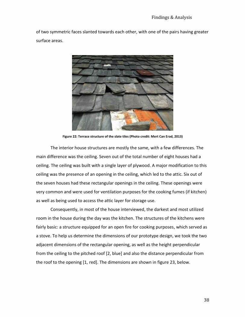
Findings & Analysis
38
of two symmetric faces slanted towards each other, with one of the pairs having greater
surface areas.
Figure 22: Terrace structure of the slate tiles (Photo credit: Mert Can Erad, 2013)
The interior house structures are mostly the same, with a few differences. The
main difference was the ceiling. Seven out of the total number of eight houses had a
ceiling. The ceiling was built with a single layer of plywood. A major modification to this
ceiling was the presence of an opening in the ceiling, which led to the attic. Six out of
the seven houses had these rectangular openings in the ceiling. These openings were
very common and were used for ventilation purposes for the cooking fumes (if kitchen)
as well as being used to access the attic layer for storage use.
Consequently, in most of the house interviewed, the darkest and most utilized
room in the house during the day was the kitchen. The structures of the kitchens were
fairly basic: a structure equipped for an open fire for cooking purposes, which served as
a stove. To help us determine the dimensions of our prototype design, we took the two
adjacent dimensions of the rectangular opening, as well as the height perpendicular
from the ceiling to the pitched roof [2, blue] and also the distance perpendicular from
the roof to the opening [1, red]. The dimensions are shown in figure 23, below.

Findings & Analysis
39
The seventh house with a ceiling did not have an opening in the ceiling. The
ceiling was well built and constructed with plywood. The last house differed the most: it
did not have a ceiling, therefore an attic. The roof was directly visible from inside the
room.
When we started soliciting homeowners’ feedback on the day lighting solutions,
we came across an interesting common trend. Since our interviews took place during
the daytime, most of the men were generally at work leaving the women to be our
interviewees. The women we interviewed had a hard time understanding and visualizing
the technologies and their functions. Therefore, the houses with women interviewees
unfortunately did not contribute to our day lighting solutions feedback data.
The houses we received feedback on about the day lighting solutions had a main
commonality: cost and maintenance. All of the houses stated that the solution had to be
cost efficient and maintainable: “ye problem itni badi nahi hain ki ispar jyada paisa
lagaya jaye” (this is not so big problem that we need to invest money on it), was the
exact words of an interviewee in the Nehri Village.
The cost of the solution being the most important factor in the decision of the
residents, solar bottle bulbs and skylights were the most prevailing options. Although
people found hybrid systems and solar shelves interesting, they did not see them a
Figure 23: Rough diagram of slate house dimensions

Findings & Analysis
40
feasible solution for villagers due to their cost. An interviewee in Fadle Village said, “low
cost solution is very good for a common man.” Although the Solatubes were popular,
they ultimately came to the conclusion of their maintenance being difficult and the
parts hard to replace. One of the houses mentioned that a drawback to the skylights
would be water leaks if not secured in a proper way.
Figure 24: Deepak Kumal's "D.I.Y." day lighting system (Photo credit: Mert Can Erad, 2013)
Deepak Kumal, a Fadle Village resident, already had a day lighting solution of his
own. His house was the one without a ceiling. He was manually sliding a few of the slate
tiles to the side from the outside of the house, in order to create holes for the sunlight
to enter the room (see figure 24, above). It was an interesting solution that locals had
found to solve this problem. The main setback for this was its lack of protection against
rainfall, unwanted insects and animals.
4.2.2 Tin Roofs
The only tin roofed house we interviewed was in Nehri village. It had very basic
brick structured walls and big corrugated tin sheets for the roof. His house was made up
of two rooms: one for his living/bed/cooking/general purposes and the other was his
animal shed. Due to the location and difference in window size, his shed was darker

Findings & Analysis
41
than his living room. He spent a big portion of his day in his shed working with his
animals, and therefore there was a need for some additional lighting. “It’s hard to work
in the shed,” says Sunil, the only resident of the house.
Figure 25: Tin roofed house in Nehri Village (Photo credit: Nehir Keskin, 2013)
His thoughts and feedback on the different technologies we presented were
quite focused on the solar bottle bulb. For the reason being that the solar bottle bulb
was initially designed for corrugated tin/galvanized iron roof, it seemed like the most
feasible answer for his house.
4.2.3 Concrete Slab Roofs
Out of the total of five concrete slab roofed houses, three of them were in Mandi
Town (urban) and two were in Nehri Village (rural). As mentioned before in the
beginning of the section, we excluded the concrete slab roofed houses from our
implementation due to their rigid and durable structure exceeding our logistical
capabilities. Nevertheless, we have provided this part as a benchmark for potential
future projects focused on urban settings.

Findings & Analysis
42
In terms of urban areas; Mandi Town has such a compact infrastructure that the
urban houses are constructed close to one another, which creates adjacent walls with
no access to sunlight. In the villages, these houses tend to be close to the road.
Moreover, the terrain being mountainous leads them to be built on a hill causing rooms
to face the hillside, blocking their access to direct sunlight. However, the roof structure
of these houses is very basic with a flat slab of concrete layer as a roof. The rooms
generally have one window, if any, and due to this being the case: they are dark (see
figure 26, below).
Figure 26: Electricity-lit room during the daytime, Nehri Village (Photo credit: Nehir Keskin, 2013)
Even though the concrete slab houses in rural and urban settings share the same
roof structure, they tend to differ in notion. When we inquired their feedback on the
day lighting solutions: the houses in Nehri Village were more focused on the cost as the
main factor of decision, whereas Mandi Town seemed to be more focused on having an
Findings & Analysis
43
efficient solution, regardless of the cost. The hybrid lighting systems seemed to be the
most desired option for the urban residents.
Part 2: Discussion
Our quantitative data indicates that electricity bill costs were not as significant
for the residents as we had suspected them to be. Especially since most of the houses
utilize other heavy electricity requiring appliances in their homes, the electricity cost of
daytime lighting is relatively low. Our data (rural Rs. 379, urban Rs. 558) also show that
urban area residents depend more on electricity use in their daily lives than rural area
residents. Nevertheless, with 67% being the percentage of stated interest, we can infer
that even though the electricity cost is a less significant criterion, the participants would
still prefer sunlight in their houses.
We also observed that urban house residents were more hesitant towards
talking to us than people in rural areas. The reason of this difference can be the lack of
trust towards other people, whereas in villages, people are socially more reliant on each
other. Moreover, as we got further away from the IIT campus, the residents were less
open toward inviting our team to their houses to ask them questions. This might link to
them being less acquainted to IIT, and therefore lest trustful towards elements related
to it.
Another interesting finding was the women’s lack of understanding and ability to
visualize the existing day lighting solution. Although in one house in Fadle Village, the
wife’s understanding of the technologies and her valuable suggestion surprised us. We
then discovered that she was a teacher whose access to education indicates a vital role
in this specific challenge. Additionally, the women that were in the position of being the
only deciding member of the house during our interactions also made them hesitant to
respond (see figure 27, below). The reason for this was that they wanted to consult their
husband and have them make the final decision. The reasons to this might be the fact
that the predominant family structure in India is patriarchy.

Findings & Analysis
44
Figure 27: Women in Nehri Village - from various different households, all together
(Photo credit: Nehir Keskin, 2013)
In the rural settings, residents were mostly interested in solar bottle bulbs,
skylights and solatubes. Low cost and easy maintenance were the most important
aspects the residents focused on while evaluating the different options. Due to the
solatubes being less common and not easily maintainable, they were a less popular
alternative. Esthetics did not come up as an important issue for the villagers. In the case
of urban settings, Mandi Town residents did not seem to give as much of an importance
to cost as the villagers. They stated that hybrid lighting systems would be a great
solution for their concrete slab houses. This showed that they were more willing to pay
whatever necessary, as long as their problem was fixed.
Finally, we were struck by the depth of community bonds in the rural villages. All
of the households in each village were well acquainted to each other; they were much
closer than just “neighbors”. This community engagement helped us immensely in our

Findings & Analysis
45
sampling process. Each house resident guided us to our next sample house, and so on so
forth; which allowed us to execute snowball sampling.
In sum, the analyses of our findings helped us understand that the most feasible
day lighting solution for slate roof structured houses is a retrofitted design of the solar
bottle bulb. By using the mobility of the slate tiles to our advantage, we can come up
with a simple design to satisfy the community needs for day lighting. As for the tin
house, the most feasible options are the solar bottle bulb and a crude configuration of a
skylight. Finally, combining the common trends of each village and each roof type
helped us further evaluate the general physical infrastructure of local communities and
allowed us to move on to our next objective, by forming a solid understanding of
structural integrity.
Part 3: Prototype Design and Implementation
In this section, we will elaborate on the processes we followed in order to complete our
third objective.
Step 1: Prototype Design
One of the major milestones of our project was the prototype design and
implementation process. After the completion of our first two objectives, we formed a
significantly strong comprehension of the local communities’ interest, need and
understanding towards our project. Moreover, we investigated further the physical
infrastructure of the houses and their roof structures in the surrounding villages to start
designing our prototypes. By combining the results of our in-depth interviews, previous
day lighting systems research and analytical thinking skills our engineering background
provided us with, we created a design that is most suitable for the local architectural
structure.
Five sample houses were selected for our implementation. We selected them
based on the highest interest shown by the residents during our interviews along with
them being most logistically feasible. Logistical feasibility was a major factor in our
selection, due to our constructional limitations. We had to plan the implementations

Findings & Analysis
46
according to our level of building skills and also in a way that we would least disrupt the
structural integrity of the building. Taking the strength of local community into
consideration, we aimed to implement on houses from different areas, in order to
ultimately collect a variety of observations for our last objective. We selected these five
houses from a total of three different communities. We tried to choose a variety of
different roof structures to work with, in order to see the differences in residential
feedback after the implementation.
The first two sample houses were located in Roprigad Village, and the third was
in Fadle. The roof structures of the three sample houses were very similar: a pitched
slate roof and a plywood layer serving as a ceiling for the rooms of the house. All three
of these houses had rectangular openings in their ceiling, as previously mentioned:
being used for ventilation and storage purposes. Using the structural similarities of the
houses to our advantage, we worked towards forming a similar design for all three
houses.
From our interview analyses, we had found that people in the rural areas whom
lived in slate and tin roofed houses leaned more towards solar bottle bulbs. When we
considered using the solar bottle bulb for these three houses, but the fact that they had
a ceiling was a major obstacle in the functionality of the system. Since the solar bottle
bulb works as a regular light bulb, it is a scattered rather than a focused light source.
Therefore when the solar bottle bulb is implemented on the roof, most of its light
illuminates the attic, which is the not serviceable. In figure 28 below, the red box
indicates the excessive light being squandered on attic illumination. (See Appendix B for
sample photographs of the ceiling opening).

Findings & Analysis
47
Our analysis of this problem lead us to the conclusion that the original solar
bottle bulb would not be the best practice for the given house structure. Instead,
conducting further research and consideration lead us to the idea of an adaptation of
the solar bottle bulb. Our retrofitted design (“solar bottle cone”) was a 45.72cm by
91.44cm (1.5 ft. by 3 ft.) soft tin sheet rolled around the solar bottle in the shape of an
upside down cone in order to focus the sunlight through a smaller cross sectional area
(see figure 29, below). Cutting a slit through the sheet and folding the corner end of it
through the slit allowed the tin to brace and form the cone figure without the need of
an adhesive substance. The narrower end of the cone was stuck onto the prototype via
the use of epoxy. This design allowed us to transmit the sunlight directly into the room,
eliminating its unnecessary dispersion into the unused attic.
Figure 28: Slate house with ceiling opening - light distribution into the attic

Findings & Analysis
48
Similar to the first three houses,
the fourth sample house located in Fadle
Village also had a slate roof structure.
What differentiated this one from the rest
was the fact that it did not have a ceiling;
therefore the entire slate roof was visible
from inside the room. Also, another
difference was that the incline of the roof
was less than the other slate houses;
allowing the roof to be lower and
therefore closer to the top of the room
(see figure 30, below).
Figure 30: The house with no ceiling - slate structure (Photo credit: Mert Can Erad, 2013)
Figure 29: Solar bottle cone (Photo credit: Nehir Keskin, 2013)

Findings & Analysis
49
A miscellaneous advantage of the roof incline being at a smaller angle is its outer
surface being exposed to sunlight for a more extensive amount of time, causing the
longer use of daylight indoors. The best interior lighting solution for this house was
using the original solar bottle bulbs. The light scattering nature of the prototype allows
the light to diffuse into the room without any
disruption.
During our prototype assembly, we
altered the solar bottle bulb prototypes we used
on the slate roofs. The original design proposes
the base sheet of the solar bottle bulb to be
corrugated. The reason for this was for the
pattern of the base sheet to match the
corrugated roof structure of the houses they
were initially pioneered on. Whereas the houses
we worked with had flat slate roof tiles, in which
could be replaced with the prototype in order for
implementation to take place. This suggested the
base sheet to be similar to that of a slate tile,
therefore flat rather than corrugated (see figure
31, right). Ultimately, on the contrary to the original design of the base sheet being
corrugated, we modified our prototype by using flat tin base sheets. This modification
was also applied to our retrofitted design, the solar bottle cone.
In terms of material for the base sheet, we thought aluminum was too soft to
support the weight of a two-liter solar bottle bulb, and iron would oxidize due to high
humidity levels and heavy rain of the region, and rust. Rusting would cause the metal to
get weaker by time and ultimately cause the water proofing to wear off. For these
reasons, we used hard tin as base sheet material.
Our implementation consisted of the replacement of a slate tile with our
prototype. While building the prototype, we realized that because the tin base sheet
Figure 31: Solar bottle bulb with a flat base sheet (Photo credit: Nehir Keskin, 2013)

Findings & Analysis
50
was thinner than the slate tiles, and the exact size, it would cause a water leakage
problem during the rain. After conducting further testing and research, we made the
base sheet of the prototype larger than the slate tile itself to allow greater coverage
area. The dimension of an average slate tile being 40cm by 18cm, our base sheet came
out to be around 60cm to 24cm. By this modification, the prototype would contribute to
giving the entire roof better structure to transfer the rainwater. It allows the water to
flow from the upper rows of the terrace-like arrangement all the way down, without
causing any of the water to infiltrate the house from sides of the tiles.
Lastly, the fifth sample house had a basic tin roof made out of multiple
corrugated tin sheets bolted to each other. This house was in the village of Nehri. The
original design of the solar bottle bulb was initially pioneered on corrugated tin roofs
throughout the world, making the use of solar bottle bulbs on tin roofs a logical option.
Even though the original design demands the use of solar bottle bulbs on corrugated
roofs, we decided to use the skylight technology instead. The reason behind our
decision was to be able to use a variety of day lighting technologies. We used a
corrugated transparent plastic sheet as our simple skylight prototype. The skylight
allowed the room to be lit up with the sunlight, covering a large surface area while doing
so.
Step 2: Prototype Implementation
At the mechanical engineering lab on the Kamand campus, we obtained tools
such as a drill bit, an electric drill, a wrench, pliers, tin cutters, hammers, nuts, bolts and
washers. With the help of the machine shop technicians, we had the opportunity to
practice drilling and cutting tin sheets beforehand.
The implementation process for the slate roofed houses was rather simple. By
using the mobility of the slate roof tiles to our advantage, from the outside of the house,
we replaced the solar bottle bulb base sheet with a slate roof tile. We left the lower 2/3
of the water bottle inside of the house while the top was left to the exposure of the sky.
By using an 8mm drill bit, we drilled a centered hole 3cm away from the top end of the
tin sheet. In some cases, we hammered the hole in using a nail. This allowed us to nail

Findings & Analysis
51
the upper end of the base sheet on the incline and fix the prototype into the roof (see
figure 32, below). Therefore, alongside the weight of the slates keeping the slates
steady, the nails held the slates from sliding down.
The location of the prototype implementation on the slate roofs was determined
by taking into consideration the most efficient illumination scenario and physical
feasibility. Due to the slate roofs being as fragile as they are, we were not able to stand
on them while implementing. With the help of a ladder, we implemented them onto the
highest slate tile we could reach. We tried to implement them over the darkest area of
the target room. All rooms except for the one living room in a Fadle Village house; were
kitchens. This being the case, we had to take into consideration the position of the stove
(open flame) and worked towards not implementing directly over it to avoid the smoke
from damaging our prototype.
Finally, our last implementation was on the animal shed of the tin roofed house
in Nehri Village. There were already five large windows in the room, but the lack of
Figure 32: Solar bottle bulb implemented on a roof. The nail is not visible because the upper two slates are covering it. (Photo credit: Siddhant Mohan, 2013)

Findings & Analysis
52
sunlight still seemed to be a problem. The roof was made out of 18 gauge (1 mm)
corrugated galvanized iron/tin sheets, making the roof difficult to cut. Our plan was to
cut a rectangular whole in the roofing material and cover it with the corrugated clear
plastic sheet as a crude skylight. By using the metal scriber and tape measure, we
measured 4 cm inwards from each end of the plastic to get the dimension of the
rectangular hole that we were going to cut out of the roof. The reason behind this was
to leave room for drill holes on the edges. We then laid the plastic sheet over the
rectangular hole and drilled a total of 18, 8mm holes through the plastic and roof and
bolted them by using nuts and washers (see figure 33, below). In order to make the
prototype watertight, we used epoxy as insulation material (see Appendix B for detailed
photos of the tin roofed house).
Figure 33: Photograph of the simple skylight prototype (Photo credit: Mert Can Erad, 2013)
In conclusion, our design and implementation process was overall a success. We
did not face major problems during the completion of this objective, allowing us to
move on to our fourth objective.
Findings & Analysis
53
Part 4: Observations of Implementation
An average of one week was given to the sample houses after implementation,
as a trial period to familiarize with the prototypes. During that one-week, the local
weather was various: sunny, cloudy and rainy. Fortunately, we were lucky enough to
have had the residents test the prototype in every possible weather scenario.
When we returned to the slate roofed houses after implementation, instructions
on making the solar bottle bulb prototype were given to the residents. Additionally, we
explained to them that they could relocate the prototype according to whichever slate
tile they chose. Relocating was simple: all they needed to do was take the base sheet of
the prototype out of its current nail and put it through the nail in the new location.
Positioning the base sheet would be the hardest part: tucking the sheet under the upper
level tiles was essential for water leakage control. After giving them these disclaimers
and instructions, we proceeded with our observations.
All five of the sample house residents were generally happy with their prototype.
They stated that when there was sun it worked perfectly. Nevertheless, they expressed
that when the clouds blocked the direct sunlight, the effectiveness would decrease. The
residents of the house without a ceiling at Fadle Village were comparing the prototype’s
illuminance with a light bulb. Although they were happy with the free supplemental
light, their expectations were higher.
When we asked the residents what had changed in terms of electricity use in the
implementation room, both slate roofed houses from Roprigad Village stated that they
were no longer using their light bulbs to light up the kitchen as long as there was
enough direct sunlight. The two houses from Fadle Village also responded the same
way. Sunil, the dweller of the tin roofed house in Nehri Village emphasized how happy
he was with the implementation and that he also was not using an artificial light in his
shed anymore.
In the duration of the one-week trial period, where we received heavy rain, none
of the slate roofed houses had experienced any leakages. However, Sunil mentioned
that there was a slight leak in his roof due to the roof being corrugated and hard to fully

Findings & Analysis
54
seal. We later on went back to his house and fixed the problem by applying rubber
cement in the openings between the plastic material and the roof sheets.

Results & Conclusion
55
Chapter 5. Results and Conclusion
Overall, our observations gave us confidence that the implementation process
was a success and that the residents had a positive outcome from our project. We
devised a set of results and recommendations, by compiling and further analyzing our
findings and observations. Since solar bottle bulbs were originally designed and
implemented on roofs with corrugated tin sheets, this project was significant because it
was the first of its kind to be implemented on slate tiled houses.
Part 1: Results & Recommendations
Our work on concrete slab houses through surveys and interviews helped us to
understand the structural integrity of these houses. Even though they exceeded the
scope of our project, we formed a few simple recommendations for future possible
projects that focus on such structures.
To look for inspiration we visited the home of the IIT director Dr. Gonsalves,
which is located on the IIT Kamand campus. The building was constructed around a
central atrium that was open on the top. The rooms of the house opened to the
naturally lit atrium, utilizing the sunlight coming from it. The roof around the opening
uses semi-translucent fiberglass to provide as much light as possible to shine through. It
was built for the purpose of utilizing natural daylight, in turn eliminating the need to use
electricity for lighting during the day. By observing how successfully this house benefits
from daylight, from a structural point of view, we recommend concrete roofed houses
to be built with an atrium that allows the distribution of the sunlight into the rooms
(see figure 34, below).

Results & Conclusion
56
Figure 34: Director's house interior design (Photo credit: Matt Shanck, 2013)
Furthermore, combining our fieldwork and research of the existing day-lighting
solutions helped us come to the conclusion that Hybrid Lighting Systems (HLS) are a
feasible, yet relatively higher budget fit for urban concrete slab houses in Mandi.
Slate roofed houses were the main focus of our project. The analysis of our
observations on the post-implementation helped us understand that our retrofitted
solar bottle cone as well as the solar bottle bulb made a significantly positive difference
on the residents’ lighting methods, as well as the illuminance of the rooms. Additionally,
all of the houses on which we implemented stated that they stopped using electricity for
lighting in the rooms during the day, in only one week after the installation.
We concluded that even on a cloudy day where there was a lack of direct
sunlight, there was a considerably noticeable distinction in the lighting of the rooms. As
can be seen below, the following unedited figures were taken at the same time with the
same angle to visually display difference in lighting. The images, in sequence, indicate
the lighting without the prototype functioning (blocked from sunlight) and with the
prototype exposed to sunlight:

Results & Conclusion
57
Figure 35: Fadle Village House #1 [with no ceiling] kitchen (Photo credit: Nehir Keskin, 2013)
Figure 36: Fadle Village House #1 kitchen, from different angle (Photo credit: Nehir Keskin, 2013)

Results & Conclusion
58
Figure 37: Fadle Village house #2 living room (Photo credit: Nehir Keskin, 2013)

Results & Conclusion
59
Figure 38: Roprigad Village house #1 kitchen (Photo credit: Vivek Vishwakarma, 2013)

Results & Conclusion
60
Figure 39: Roprigad Village house #2 kitchen (Photo credit: Vivek Vishwakarma, 2013)
Noting that figure 37 was taken on a cloudy day; it is evident that the difference
of lighting in the rooms is significant.
We also conducted detailed light measurements in the lab using a lux meter to
further prove and understand the intensity of the light. Our experiments showed that
the solar bottle bulb emits an average of 850 lux (unit of illuminance) while exposed to
the sun, compared to a fluorescent light bulb with a 1300 lux illuminance. This number
Results & Conclusion
61
fluctuates according to the intensity of the sun, but the average value on a cloudy day is
100 lux. These results further prove our comparison of the solar bottle bulb to a 50Watt
light bulb. Interestingly, our experimentations also displayed that the lux from a skylight
with the same diameter of the solar bottle is only half the intensity. This last finding
shows the diffusive power of the solar bottle bulb, which makes it similar to a light bulb.
It is important to take into consideration the daily path of the sun while finding a
location to implement the prototype. The system is at its optimum efficiency when it
received the most amount of sunlight possible. Similarly, we recommend that
implementing more than one solar bottle bulb would result in a more efficient lighting
scenario. This technique would allow the prototypes to cover a larger area, therefore
leading to a better-lit room. Furthermore, our retrofitted design’s conical and reflective
structure allows the light to be transmitted through a specified distance.
In terms of the prototype construction, we recommend to use larger
dimensions than the replaced slate tiles in order to avoid any water leakage that can
occur from the side cracks. Because the existing design and instructions for a solar
bottle bulb do not specify the shape of the plastic bottle being used, we recommend
using a bottle with curvature so that the end of the bulge can be a support for the
base sheet. Globally speaking, if the solar bottle bulb were to be implemented in a
region, which the temperature falls below freezing point, we recommend further
looking into the possible use of antifreeze. Also testing and accordingly increasing the
bleach-to-water ratio can be a solution in order to alleviate the freezing temperature
of the liquid in the bottle.

Results & Conclusion
62
Figure 40: Nehri Village tin roofed house (Photo credit: Nehir Keskin, 2013)
Finally, we came to the result that skylights illuminate, regardless of the presence of
direct sunlight. The image above (figure 40) was taken from two different angles, but
shows the advantage of skylights. For further fieldwork photographs, see Appendix C for
our photographic journal.
Part 2: Conclusion
Throughout the duration of our project, we strived to bring “appropriate
technology” attributes to our prototype. The result is simple and small-scaled,
sustainable (a 4-5 year lifespan); energy efficient and easily maintainable. Furthermore,
the installation and maintenance skills are easily transferrable within the community.
We observed that all of the households in our study had stopped using light
bulbs during the day in the implemented room in just one week. We achieved our
overall project goal to “reduce the inefficiency of daytime lighting and energy use
through the application of both affordable, easily accessible and feasible solar day
lighting systems, and to record the residents’ perceptions after their implementation”.
This field of study has the potential to grow into something extraordinary.
Observing the local response to these alternative technologies helped us understand the

Results & Conclusion
63
level of awareness we have raised in the community. From a social standpoint, our
project correlated with the needs and habits of the subjected residents.
While conducting our project, the value of joint international collaboration was
immense. Cooperating in an international set of students helped us each understand the
complexity of identifying local need and interest, along with supporting community
resilience, and the perspectives that we each brought to the project. Our work guided us
to enable self-reliance within the communities and in a very small way, helped to reduce
vulnerability.
In the limited time of seven weeks, we were able to substantially impact five
households. Furthermore, by using our project as a baseline, the outcomes of our
solution can be attained in a global scale. Our findings and results can be applicable to
any community, with minimal modifications. We aspire for our project to ignite many
more to come and ultimately achieve the appropriate technology criteria of being
“globally applicable”.

Bibliography
64
Bibliography
Aggarwal, R. K., & Chandel, S. S. (2010). Emerging Energy Scenario in Western
Himalayan State of Himachal Pradesh. Energy Policy, 38(5), 2545-2551. doi:
10.1016/j.enpol.2010.01.002
Almusaed, A. (2011). Illuminate by Light Shelves (pp. 325-332). London: Springer
London.
Andrew, R. (2012). Building Community Resilience. Proceedings of the Institution of Civil
Engineers-Civil Engineering, 165(6), 59-64. doi: 10.1680/cien.11.00051
Anonymous. (2012). A Litre of Light. Appropriate Technology, 39(4), 29.
Anonymous. (2013). Chinese Proverbs from
http://www.quotationspage.com/quotes/Chinese_Proverb/
Beltran, L. O., Lee, E. S., Papmichael, K. M., & Selkowitz, S. E. (2008). The Design and
Evaluation of Three Advanced Daylighting Systems: Light Shelves, Light Pipes and
Skylights.
Berg, B. L., & Lune, H. (2012). Qualitative Research Methods for the Social Sciences.
Boston: Pearson.
Blomberg, J. (2004). Climate Change in India: Forgotten Threats, Forgotten
Opportunities. (2010). Economic & Political Weekly.
Chel, A., Tiwari, G. N., & Chandra, A. (2009). A Model for Estimation of Daylight Factor
for Skylight: An Experimental Validation Using Pyramid Shape Skylight Over Vault
Roof Mud-House in New Delhi (India). Applied Energy, 86(11), 2507-2519. doi:
10.1016/j.apenergy.2009.03.004
Commissioner, (2011a). Mandi Houses, Household Amenities and Assets.
Commissioner, (2011b). Provisional Population Totals.
Cover Photo, (2013). JPEG from
http://www.gdefon.com/download/lightbulb_sun_sunset/1833/1280x1024

Bibliography
65
District Mandi, (2001). Mandi Fact File from
http://hpmandi.nic.in/fact.htm
Doyle, James K. (year unspecified). Handbook for IQP Advisors and Students, Chapter
11: Introduction to Interviewing Techniques
Edwards, L., & P. Torcellini (2002), A Literature Review of the Effects of Natural Light on
Building Occupants, Colorado: National Renewable Energy Laboratory.
Eijadi, D. A., Abraham, L., Dekeyser, D., & Hansen, T. A. (1901).
Fiedler, D. (2013). Lighting Up India. Retrieved 4/2/2013, from
http://aliteroflight.org/2013/04/lighting-up-india/
Fontoynont, M., Zimmerman, A. (2005). On the Energy Efficiency of a Prototype Hybrid
Daylighting System. Solar Energy, 79(1), 56-64. doi:
10.1016/j.solener.2004.09.014
Graham, I., & Ebrary Academic, C. (2010). Global Warming: A Very Peculiar History.
Brighton: Book House.http://aliteroflight.org/2013/04/lighting-up-india/
Hazeltine, B., & Bull, C. (1999). Appropriate Technology: Tools, Choices and Implications.
San Diego: Academic Press.
Housetrends, (2013). JPEG image, from
http://www.housetrends.com/images/HTCO%20client%20pages/Solatube-
Smart-LED-System-sm.jpg
Hunt, C. I. (1994). Development and Disempowerment : Appropriate Technology in
Development Aid in the High Himalaya. (Dissertation/Thesis). Retrieved from
http://wpi.summon.serialssolutions.com/link/0/eLvHCXMwY2BQAE1mJhoYpBqb
m5obJ5qaAmsUS5NUg5TENFOjZIskE5QbIpBKczdRBl031xBnD93SpOT4FGCOSk6N
Bx1_nJxZBAzDeJBocmI8sFKxjDexsLQwFGNgAfaRUwEEUx1J
International, S. (2010). Company Website. from
http://www.solatube.com/?_kk=solatube&_kt=b53a82d7-dce5-4b17-b974-
6986d28e1b9a&gclid=CJb5reOtsLYCFaZFMgodRQ0Amw
Jensen Iii, H. P. (1901).

Bibliography
66
Klaasen, M. (2011). Solar Bottle Light. from http://lighttalk.via-
verlag.com/2011/06/solar-bottle-light/
Liwanag. (2012). How to Build a Solar Bottle Bulb. from
http://www.instructables.com/id/How-to-build-a-SOLAR-BOTTLE-BULB/
Makhaik, R. (2013). SJVN eyes Jaypee hydropower plants in Satluj valley.from
http://hillpost.in/2013/09/sjvn-eyes-jaypee-hydropower-plants-in-satluj-
valley/96122/
Mayhoub, M. S., & Carter, D. J. (2010). Towards Hybrid Lighting Systems: A Review.
Lighting Research & Technology, 42(1), 51-71. doi: 10.1177/1477153509103724
Muhs, J. D. (2008). Design and Analysis of Hybrid Solar Lighting and Full-Spectrum Solar
Energy Systems.
Parans, (2013).
http://www.parans.com/eng/sp3/
Parans (Writer). (2013). Presentation of Parans.
Parans Webpage, P. Parans Official Webpage. from http://www.parans.com/eng/
Rodriguez, G., & Siret, D. (2006). Daylight at Home: Differences between Developers and
Architectural Competition Houses.
Sarkar, R. (2011). “Kamand” Campus & Its Surrounding Environs: Impressions of a Brief
Sojourn (pp. 49).
Skylight Design: High Performance Skylight Systems Require Careful Consideration of the
Type of Glazing and Its Interface with the Building. (1995). The Canadian
Architect, 40(6), 31.
Smith, M. C., Wendel, W. J., Sanders, & Thomas Inc Pottstown, P. A. (1963).
Illumination in Group Shelters
Smith, M. C., Sanders, & Thomas Inc Pottstown, P. A. (1963). Solutions:
Illumination in Group Shelters, Part 2. Solutions: Lighting - Project: North
Carolina Museum of Art. (2010, 2010/09/24/). Building Design, 16. +
Steffy, G. R. (2002). Architectural Lighting Design. United States.
Toms Guide, (2013) JPEG Image, from

Bibliography
67
http://www.tomsguide.com/us/slideshow/brightshelf-1,0101-271165-0-2-3-0-
jpg-.html
Tsangrassoulis, A., Pohl, W., Mihalakakou, G., Doulos, L., Santamouris, M.,
WWF (Writer). (2011). WWF and GlobalFOCUS: Parans Climate Solver.
WWF (Writer). (2013). Catalyzing Sustainable Hydropower
http://wwf.panda.org/what_we_do/where_we_work/greatermekong/our_soluti
ons/hydropower_roads/
Zobel, G. (2013). Alfredo Moser: Bottle light inventor proud to be poor. Retrieved from
BBC News Magazine website:
http://www.bbc.co.uk/news/magazine-23536914

Appendices
68
APPENDICES
Appendix A: Sample Survey Questions
1. How many family members in your house? (Details of family members)
2. Are there any people in the house during the day?
3. How many rooms in your house? Which rooms get direct and sufficient sunlight?
For how long?
4. Do you use electricity during the day to light rooms in your house?
5. If the rooms are dark, do you use any other light sources to light up the room i.e.
candles..? Are they efficient (cost wise, do they give enough light?)
6. Are there a lot of power outages during the day? If yes, how long?
7. How much is your electricity bill monthly average? (If the household uses other
sources of lighting, include the cost of that as well)
8. Would you be interested in having daylight without using electricity? (If yes, can
we come back later to ask you further questions? - If no, why?)

Appendices
69
Appendix B: Additional Data
Solar Bottle Bulb instructional video by Illac Diaz:
http://www.youtube.com/watch?v=i5YQ4t5apPM
Different roof types:

Appendices
70

Appendices
71
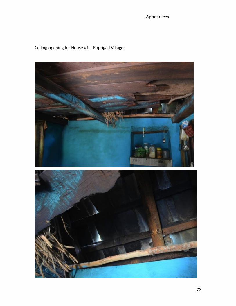
Appendices
72
Ceiling opening for House #1 – Roprigad Village:

Appendices
73
Ceiling opening for House #2 – Roprigad Village:

Appendices
74
Ceiling opening for House #3 – Fadle Village:

Appendices
75
Appendix C: Photographic Journal: Field Work and Implementation
Tin house – Nehri Village:
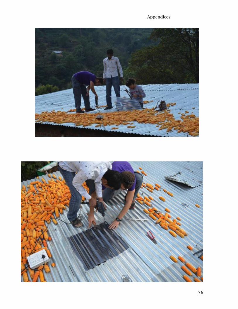
Appendices
76

Appendices
77
(View of the skylight prototype from inside the shed)
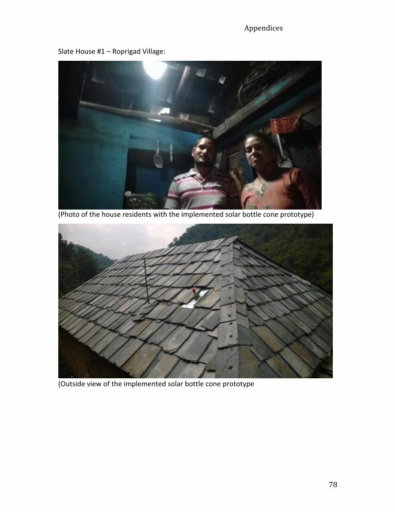
Appendices
78
Slate House #1 – Roprigad Village:
(Photo of the house residents with the implemented solar bottle cone prototype)
(Outside view of the implemented solar bottle cone prototype

Appendices
79
Slate house #2 – Roprigad Village:
(Photo of the implemented solar bottle cone from the inside of the kitchen)
(Photo of the house residents with the implemented solar bottle cone prototype)

Appendices
80
Slate house #3 – Fadle Village:
(Photo of team member Mert Can Erad hammering the nail hole)

Appendices
81
(Photo of the implemented solar bottle cone from inside the living room)

Appendices
82
(An inside photo of the solar bottle cone base sheet being nailed into place on the roof)

Appendices
83
Slate House #4 – Fadle Village (No ceiling):
(Photo of team member Nehir Keskin drilling in the nail hole onto the base sheet)

Appendices
84
(Photo of team member Mert Erad fitting the solar bottle bulb into the roof)

Appendices
85
(Photo of the solar bottle bulb from the inside of the kitchen)
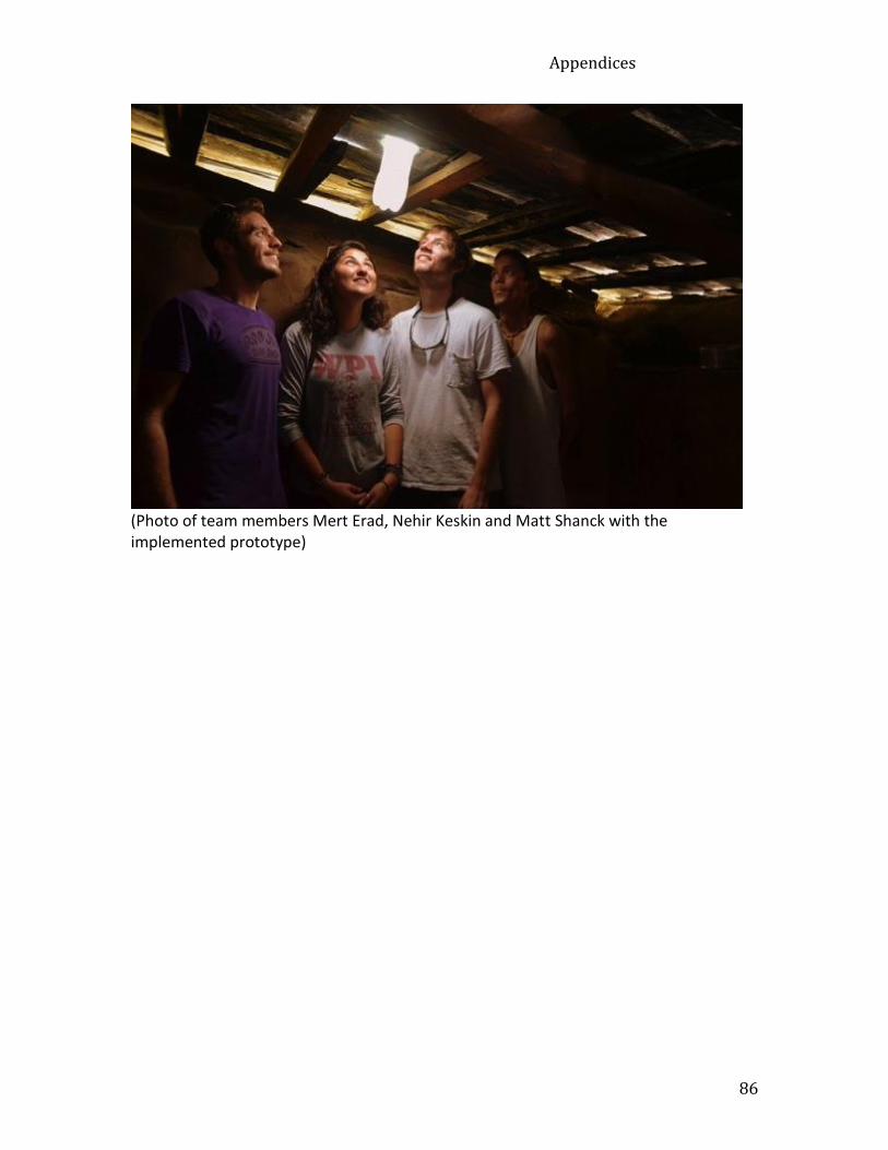
Appendices
86
(Photo of team members Mert Erad, Nehir Keskin and Matt Shanck with the implemented prototype)

Appendices
87
Appendix D: Timeline
Provided below is the timeline that we followed during our time on site in
Mandi, India.
Gantt chart of timeline
All information collected during our project, including data gathered through surveys
and interviews, remains confidential and was gathered with the consent of the
participants. All data was kept and maintained in a password-protected computer and
not be distributed. The raw data was deleted upon finalization of our project.
Group Collaboration and Bonding
Objective 1: Identitfy interest and need
Objective 2: Assess physical infrastructure
Objective 3: Create an efficient design
Objective 4: Observe outcome of…
Finalization of Report

Appendices
88
Appendix E: Presentation Poster