Embed Size (px)
Citation preview
8/20/2019 Dawson AUC2008
http://slidepdf.com/reader/full/dawson-auc2008 1/15
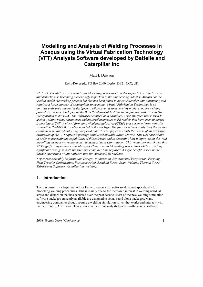
Modelling and Analysis of Welding Processes in
Abaqus using the Virtual Fabrication Technology(VFT) Analysis Software developed by Battelle and
Caterpillar Inc
Matt I. Dawson
Rolls-Royce plc, PO Box 2000, Derby, DE21 7XX, UK
Abstract: The ability to accurately model welding processes in order to predict residual stressesand distortions is becoming increasingly important in the engineering industry. Abaqus can be
used to model the welding process but this has been found to be considerably time consuming andrequires a large number of assumptions to be made. Virtual Fabrication Technology is an
analysis software suite that is designed to allow Abaqus to accurately model complex welding procedures. It was developed by the Battelle Memorial Institute in conjunction with Caterpillar
Incorporated in the USA. The software is centred on a Graphical User Interface that is used to
assign welding paths, parameters and material properties to FE models that have been imported
from Abaqus/CAE. A closed form analytical thermal solver (CTSP) and advanced user material subroutine (UMAT35) are also included in the package. The final structural analysis of the welded
component is carried out using Abaqus/Standard. This paper presents the results of an extensive
evaluation of the VFT software package conducted by Rolls-Royce Marine. This was carried out
in order to ascertain the capabilities of this software and to determine how it improves on the weldmodelling methods currently available using Abaqus stand-alone. This evaluation has shown that
VFT significantly enhances the ability of Abaqus to model welding procedures while providing
significant savings in both the user and computer time required. A large benefit is seen in the further integration of this software into the Abaqus/CAE package.
Keywords: Assembly Deformation, Design Optimization, Experimental Verification, Forming,
Heat Transfer Optimization, Post processing, Residual Stress, Seam Welding, Thermal Stress,
Third-Party Software, Visualization, Welding.
1. Introduction
There is currently a large market for Finite Element (FE) software designed specifically formodelling welding procedures. This is mainly due to the increased interest in welding residual
stress and distortion that has occurred over the past decade. Most of the new welding simulation
software packages currently available are designed to act as stand alone packages. Many
engineering companies though require a welding simulation solver that works and interacts withtheir current FEA software. This allows their current analysts to work with the new software
2008 Abaqus Users’ Conference 1

8/20/2019 Dawson AUC2008
http://slidepdf.com/reader/full/dawson-auc2008 2/15
without having to undergo extensive re-training. Also, for consistency, it is desirable to use thesame FE package for all of the various structural and thermal analyses that are performed.
This paper presents an evaluation of the ‘Virtual Fabrication Technology’ (VFT) welding analysissoftware developed by the Battelle Memorial Institute and Caterpillar Incorporated in the USA. It
assesses the functionality and capability of this software and determines how it improves on thecurrent abilities of Abaqus/CAE. It gives examples of the type of analyses that VFT is capable of
performing and compares some of these analyses with previous FE methods. The high-
temperature material modelling methods used by VFT are evaluated and the improvements to theAbaqus/Standard solver highlighted.
The VFT software has been designed to be capable of analysing many different types of welded
joints and components by working in conjunction with Abaqus/CAE and Abaqus/Standard. Of
particular interest to Rolls-Royce Marine is the ability of the software to model through thicknessresidual stress distributions in thick-section welded components. VFT has already seen use in the
US Shipbuilding and Power Generation industries.
2. Background
2.1 Welding Residual Stress
Whenever a welding procedure is applied a metallic material is subjected to very large temperaturegradients. Melting is usually achieved by the application of an electric arc or oxy-acetylene flame,
resulting in a rapid local heating of the metal in the area of the weld. The large temperature
gradients generated produce significant local plastic strain around the welded area. This results in
the formation of large residual stress fields upon cooling in the local area of the weld andsurrounding structure. As these stresses are not caused by the direct (and continued) application of
any externally applied load, they are known as ‘residual stresses’ and are generally self-balancing
within the structure.
The presence of residual stresses in a welded component can cause a number of problems. The
component will be subject to local and global distortion caused by the effects of the stress/strain
fields. The typical example of this is a groove weld on a flat plate, where contractions and plastic
strains have cause the edges of the plate to bow upwards. Tensile residual stress fields will also
encourage the initiation and propagation of defects in a material, which can be a major safetyconcern in safety critical components.
Experimental techniques can be used to determine residual stress levels at specific locations on
engineering components. However, these techniques rarely provide a complete map of the residual
stress and strain fields present in a welded component. Each measurement technique has its owncapabilities and limitations. For example, the strain relief methods requiring drilling or cutting are
either semi or fully destructive. Non-destructive measurement methods such as X-ray or neutron
diffraction are typically laboratory based and applicable to only small welded specimens. Thecosts of through thickness stress measurements are also much greater than those incurred from
performing a finite element welding simulation.
2 2008 ABAQUS Users’ Conference
8/20/2019 Dawson AUC2008
http://slidepdf.com/reader/full/dawson-auc2008 3/15
It is for these reasons that now, with the continued increase in computing power worldwide, manycompanies are starting to focus on the development of validated residual stress FE modelling
methods.
2.2 Weld Modelling Software
Finite element packages have been used to model welding procedures for about twenty-five years.
However it is only comparatively recently that specialised, user-friendly, welding simulation packages have come onto the market. Virtual Fabrication Technology (VFT) is a good example of
such a modelling tool. Before the advent of these specialised programs, the user had to manually
modify existing FE packages in order to set up an adequate welding simulation.
Welding specific software packages provide a number of advantages over this manual modellingmethod. The use of unique Graphical User Interfaces (GUI’s), heat source mapping tools,
automatic element activation and material modelling subroutines significantly increase the ease
with which welds can be modelled. It should be noted though that, despite this automation, the
basic welding analysis carried out remains relatively unchanged. It will still consist of a thermalanalysis that is either coupled or un-coupled to a highly non-linear structural analysis.
The majority of welding analysis software favours the use of an un-coupled analysis procedure. In
welding simulation this allows the thermal analysis model to be checked and validated before the
time-consuming structural analysis is performed. Welding fusion and heat-affected zones can bechecked against weld macrographs and, if necessary, the predicted temperature distribution can be
compared to measurements gained from thermocouples. The data from the thermal model can then
be used to conduct a structural analysis of the welded component.
Although this is theoretically a simple procedure, in practice the accurate modelling of the weld
path and deposition can be complex and time consuming. Without specialist software it is not easy
to successfully create a model that simulates the deposition of molten weld metal in a component
without making several large compromises (or simplifications). As an example, the following
section details the methods that are generally employed when using Abaqus/Standard andAbaqus/CAE to conduct a welding simulation.
2.3 Current Weld Modelling Methods using Abaqus
When modelling a welding procedure using Abaqus there are two distinct approaches that are
available to users. The first of these is the construction of a 2D axisymmetric or shell FE model ofthe component in question. The second involves the construction of a full 3D solid model so that a
3D block-dumped or moving heat source analysis can be performed. A block-dumped analysis is
one where the weld bead is deposited in several discrete steps. As a lot of literature on applying
these methods is already available they will only be summarised in brief here.
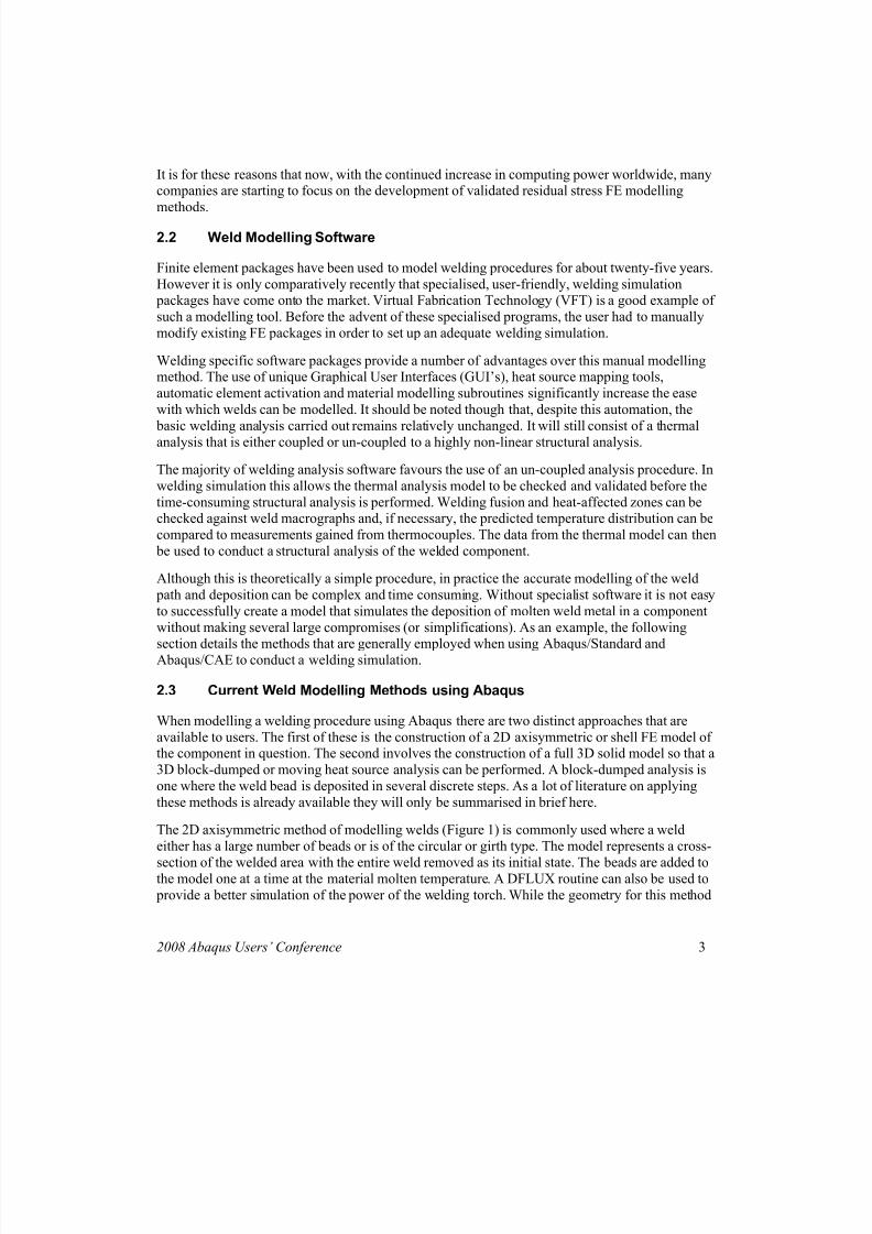
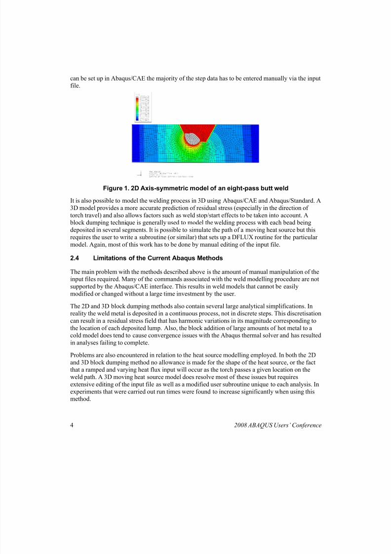
The 2D axisymmetric method of modelling welds (Figure 1) is commonly used where a weld
either has a large number of beads or is of the circular or girth type. The model represents a cross-
section of the welded area with the entire weld removed as its initial state. The beads are added tothe model one at a time at the material molten temperature. A DFLUX routine can also be used to
provide a better simulation of the power of the welding torch. While the geometry for this method
2008 Abaqus Users’ Conference 3
8/20/2019 Dawson AUC2008
http://slidepdf.com/reader/full/dawson-auc2008 4/15
can be set up in Abaqus/CAE the majority of the step data has to be entered manually via the inputfile.
Figure 1. 2D Axis-symmetric model of an eight-pass butt weld
It is also possible to model the welding process in 3D using Abaqus/CAE and Abaqus/Standard. A
3D model provides a more accurate prediction of residual stress (especially in the direction of
torch travel) and also allows factors such as weld stop/start effects to be taken into account. A block dumping technique is generally used to model the welding process with each bead being
deposited in several segments. It is possible to simulate the path of a moving heat source but this
requires the user to write a subroutine (or similar) that sets up a DFLUX routine for the particular
model. Again, most of this work has to be done by manual editing of the input file.
2.4 Limitations of the Current Abaqus Methods
The main problem with the methods described above is the amount of manual manipulation of theinput files required. Many of the commands associated with the weld modelling procedure are not
supported by the Abaqus/CAE interface. This results in weld models that cannot be easily
modified or changed without a large time investment by the user.
The 2D and 3D block dumping methods also contain several large analytical simplifications. Inreality the weld metal is deposited in a continuous process, not in discrete steps. This discretisation
can result in a residual stress field that has harmonic variations in its magnitude corresponding to
the location of each deposited lump. Also, the block addition of large amounts of hot metal to acold model does tend to cause convergence issues with the Abaqus thermal solver and has resulted
in analyses failing to complete.
Problems are also encountered in relation to the heat source modelling employed. In both the 2D
and 3D block dumping method no allowance is made for the shape of the heat source, or the factthat a ramped and varying heat flux input will occur as the torch passes a given location on the
weld path. A 3D moving heat source model does resolve most of these issues but requires
extensive editing of the input file as well as a modified user subroutine unique to each analysis. In
experiments that were carried out run times were found to increase significantly when using thismethod.
4 2008 ABAQUS Users’ Conference
8/20/2019 Dawson AUC2008
http://slidepdf.com/reader/full/dawson-auc2008 5/15
3. Virtual Fabrication Technology
3.1 Introduction and Description
Virtual Fabrication Technology (VFT) is a welding simulation software package that has been
developed by Battelle and Caterpillar in the USA (Brust, 2006). Its primary function is to simplify
the modelling of residual stresses and distortions in welded structures by use of a user friendly
GUI and advanced thermal and material modelling techniques.
Development started on the VFT software package in 1995 as a joint partnership between
Caterpillar and Battelle (Yang, 2003). The software has since been implemented across Caterpillar
and has been adopted by several other US companies, many in the marine and shipbuilding
industries. In the UK, TWI and Rolls-Royce are the main users of this software (Bagshaw, 2007).Battelle have been running a rolling update/improvement program for VFT since 2001 and they
intend to continue this into the future (Brust, 2006).
VFT is designed to run in either a Unix or Windows based PC environment. It requires at leastversion 6.5 of Abaqus/Standard and Abaqus/CAE to be available on the same machine for the full
functionality of the software to be gained. The software package itself does not require very high
system specifications to run, but run times will be reduced with higher spec machines.
The Graphical User Interface (GUI) is a Windows based interactive program that uses the standardWindows layout and functionality. The remainder of the programs contained in the VFT package
are run via a command prompt, in a similar fashion to Abaqus/Standard.
3.2 Components - Graphical User Interface
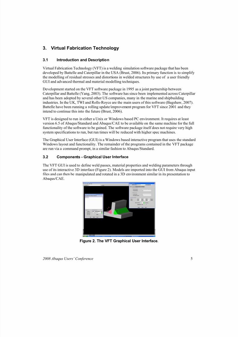
The VFT GUI is used to define weld passes, material properties and welding parameters through
use of its interactive 3D interface (Figure 2). Models are imported into the GUI from Abaqus inputfiles and can then be manipulated and rotated in a 3D environment similar in its presentation to
Abaqus/CAE.
Figure 2. The VFT Graphical User Interface.
2008 Abaqus Users’ Conference 5

8/20/2019 Dawson AUC2008
http://slidepdf.com/reader/full/dawson-auc2008 6/15
The GUI can be used to define welding passes on a model in a number of different ways. Thesevary from a simple text input method to a ‘point and pick’ selection method using the 3D
graphical representation of the welding model. Welding parameters can be entered into a database
and then assigned to as many weld passes as necessary. Material properties are assigned in asimilar fashion.
A variety of display options allow the user to edit how the model is viewed and what nodes andelements are subject to labelling. The orientation of the model is controlled by a series of
interactive buttons and drop down menus. Individual weld passes and model sections can beremoved from the viewpoint for clarity of presentation.
The GUI saves files in a unique “file.vft” file format. This allows 3D representations of a welding
model to be saved and loaded back into the GUI at a later date for further editing. The input files
for both the thermal and structural analysis runs are generated automatically by the GUI. The userhas the ability to change the naming procedure used for these files but they are all exported to the
directory in which the .vft file has been saved.
3.3 Components – CTSP Solver
The Comprehensive Thermal Solution Procedure (CTSP) program is a closed form analytical
thermal solver developed and distributed by Battelle (Brust, 2006). The input files for it are
automatically generated by the VFT GUI software but are in a text format that can be edited by theuser if required. CTSP is executed through a command prompt window. It outputs progress to this
window in the style of Abaqus/Standard.
CTSP creates several results files detailing nodal temperatures at different time steps. Theseresults files are used as an input for the Abaqus/Standard structural analysis.
CTSP is an extremely rapid thermal solver. This is primarily due to it using an analytical rather
than a numerical solving routine (Brust, 2006). Also, the ability of the user to set a ‘cut off’
temperature below which nodal temperatures will not be calculated stops the software spendinghours calculating temperatures in the far field region that are of no consequence to the analysis of
the weld.
CTSP is capable of providing a thermal solution for the vast majority of known welding joints andconfigurations. It is also possible to select if a ‘moving arc’ heat source, or a ‘block dumped’
deposition sequence is to be used. These (and other) parameters are all set using the VFT GUI.
There are two main CTSP programs packaged with VFT: CTSP-Solid and CTSP-Shell (Brust,
2006). These are used to analyse 3D solid and shell models respectively. Several other CTSProutines are contained in the software package for the analysis of new welding methods including
Laser and EB welding.
3.4 Components - CTSP–Temp
This program is an add-on to the CTSP solver routine. It allows an Abaqus odb file to begenerated directly from the CTSP output thermal data. This allows thermal results to be viewed in
Abaqus/Viewer before the structural analysis is initiated.
6 2008 ABAQUS Users’ Conference
8/20/2019 Dawson AUC2008
http://slidepdf.com/reader/full/dawson-auc2008 7/15
The program takes the form of an executable file that is run from a command prompt window. Aswith the CTSP program, data is output to this command window to update the user on the progress
of the generation of the odb file.
3.5 Components - UMAT35-Weld
This software is an Abaqus/Standard user subroutine developed by Dr Pingsha Dong in
conjunction with Battelle and Caterpillar Inc. (Dong, 1997). It is an extensive high-temperaturematerial modelling UMAT that modifies the Abaqus/Standard solver routine to take into account
factors such as annealing, phase change and different material hardening models.
The UMAT35 routine is designed to be used as a ‘black box’ analysis tool. Its code does not needmodification by the user at any point. All information relating to a specific welding model
(annealing temperature etc) is output from the VFT GUI in the form of a Fortran object file. This
object file is then combined with the UMAT35 routine by use of a small executable file
‘ucombine.bat’ that is packaged with the software. Thermo-mechanical material data is contained
in a separate user generated text file.
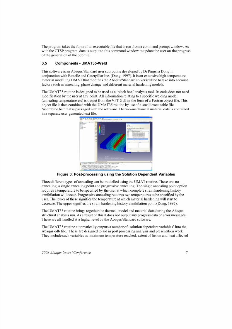
Figure 3. Post-processing using the Solution Dependent Variables
Three different types of annealing can be modelled using the UMAT routine. These are: noannealing, a single annealing point and progressive annealing. The single annealing point option
requires a temperature to be specified by the user at which complete strain hardening history
annihilation will occur. Progressive annealing requires two temperatures to be specified by the
user. The lower of these signifies the temperature at which material hardening will start to
decrease. The upper signifies the strain hardening history annihilation point (Dong, 1997).
The UMAT35 routine brings together the thermal, model and material data during the Abaqus
structural analysis run. As a result of this it does not output any progress data or error messages.These are all handled at a higher level by the Abaqus/Standard software.
The UMAT35 routine automatically outputs a number of ‘solution dependent variables’ into the
Abaqus odb file. These are designed to aid in post processing analysis and presentation work.They include such variables as maximum temperature reached, extent of fusion and heat affected
2008 Abaqus Users’ Conference 7
8/20/2019 Dawson AUC2008
http://slidepdf.com/reader/full/dawson-auc2008 8/15
zones, areas where yielding has occurred and detail on the phases of the welded materials (Brust2006, Dong, 1997).
3.6 Use of the Software
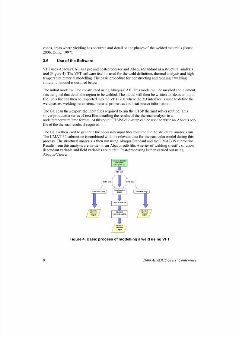
VFT uses Abaqus/CAE as a pre and post-processor and Abaqus/Standard as a structural analysis
tool (Figure 4). The VFT software itself is used for the weld definition, thermal analysis and high
temperature material modelling. The basic procedure for constructing and running a weldingsimulation model is outlined below.
The initial model will be constructed using Abaqus/CAE. This model will be meshed and element
sets assigned that detail the region to be welded. The model will then be written to file as an input
file. This file can then be imported into the VFT GUI where the 3D interface is used to define theweld passes, welding parameters, material properties and heat source information.
The GUI can then export the input files required to run the CTSP thermal solver routine. This
solver produces a series of text files detailing the results of the thermal analysis in a
node/temperature/time format. At this point CTSP-Solid-temp can be used to write an Abaqus odbfile of the thermal results if required.
The GUI is then used to generate the necessary input files required for the structural analysis run.
The UMAT-35 subroutine is combined with the relevant data for the particular model during this process. The structural analysis is then run using Abaqus/Standard and the UMAT-35 subroutine.
Results from this analysis are written to an Abaqus odb file. A series of welding specific solution
dependant variable and field variables are output. Post-processing is then carried out using
Abaqus/Viewer.
Figure 4. Basic process of modelling a weld using VFT
8 2008 ABAQUS Users’ Conference
8/20/2019 Dawson AUC2008
http://slidepdf.com/reader/full/dawson-auc2008 9/15
3.7 High-Temperature Material Modelling
Through the use of the UMAT-35 subroutine, VFT significantly expands on the high temperature
material modelling abilities already present in Abaqus/Standard. The subroutine can model avariety of different material hardening models, progressive annealing, phase transformation and
other high temperature material effects. The material models not only allow a more accurate
welding model to be run, but it has been noted that the performance of the Abaqus/Standard solver
routine is improved.
The way that material property data is handled by the UMAT35 subroutine is somewhat differentto the way that material data is usually input and used in an Abaqus/Standard analysis. The
material property data is contained in a user generated text file that is separate to the main Abaqus
input file. To allow the data to be successfully read by the subroutine, the formatting of the property file is also different from the usual Abaqus/Standard format. The amount and complexity
of material property data that needs to be generated by the user varies depending on which
material hardening model is being used.
Isotropic hardening is the baseline material model used, but bi-linear and multi-linear kinematichardening can also be modelled. Elastic-plastic creep effects can be applied if required and a
complex phase transformation model can also be run. The phase transformation model requires the
user to input a large amount of data relating to continuous cooling transformation curves. Also the
physical and mechanical properties of each of the different phases are required at various
temperatures. Although this procedure was found to be time consuming, once the property file has been written it can be re-used for any analysis by simply indicating where the material text file is
using the VFT GUI.
It should be noted that it is not currently possible to model phase transformation in Abaqus.Internal research has shown that the inclusion of phase transformation in models can significantly
alter the distribution and sign of calculated residual stresses in ferritic steel welds. The high
temperature material melting/re-melting and the type of progressive annealing modelled by the
UMAT-35 solver can also not be modelled in Abaqus stand-alone.
In the VFT manual it is stated that the UMAT-35 subroutine increases the pace at which
Abaqus/Standard can run a welding analysis as well as the chance of a successful outcome. In the
course of the evaluation procedure this has been found to be the case. Using the Abaqus/Standardsolver to model high temperature procedures has (in the past) been found to result in multiple time
step cutbacks due to the large thermal strains present. These cut backs cause the analysis to take
longer than expected and often result in the analysis terminating with an error. The UMAT-35
subroutine does seem to enhance the ability of the Abaqus/Standard solver to converge on asolution. This provides a significant time saving when complex welding processes are modelled.
3.8 Demonstration of Capabilities
In order to ensure that the VFT software package is capable of modelling the wide-variety of
components that are manufactured at Rolls-Royce Naval Marine, several complex FE models wereconstructed. These were designed to evaluate the ability of VFT to cope with correctly defining
and modelling welds on a variety of large and complex geometries. The models were each
2008 Abaqus Users’ Conference 9
8/20/2019 Dawson AUC2008
http://slidepdf.com/reader/full/dawson-auc2008 10/15
designed to test a different aspect of the Abaqus/VFT modelling process. The results from thesestudies are outlined below.
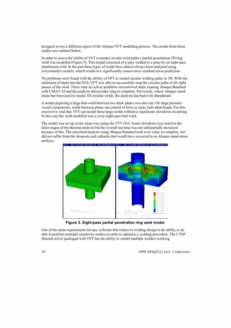
In order to assess the ability of VFT to model circular weld paths a partial penetration 3D ringweld was modelled (Figure 5). This model consisted of a pipe welded to a plate by an eight-pass
attachment weld. In the past these types of welds have almost always been analysed usingaxisymmetric models, which results in a significantly conservative residual stress prediction.
No problems were found with the ability of VFT to model circular welding paths in 3D. With the
minimum of input into the GUI, VFT was able to successfully map the circular paths of all eight
passes of the weld. There were no solver problems encountered while running Abaqus/Standardwith UMAT-35 and the analysis did not take long to complete. Previously, where Abaqus stand-
alone has been used to model 3D circular welds, the analysis has had to be abandoned.
A model depicting a large butt-weld between two thick plates was also run. On large pressure
vessel components, welds between plates can consist of forty or more individual beads. For thisreason it is vital that VFT can model these large welds without a significant slowdown occurring.
In this case the weld modelled was a sixty-eight-pass butt weld.
The model was set up in the usual way using the VFT GUI. Some slowdown was noted in thelatter stages of the thermal analysis but the overall run time was not substantially increased
because of this. The structural analysis using Abaqus/Standard took over a day to complete, but
did not suffer from the dropouts and cutbacks that would have occurred in an Abaqus stand-alone
analysis.
Figure 5. Eight-pass partial penetration ring weld model.
One of the main requirements for any software that relates to welding design is the ability to beable to perform multiple sensitivity studies in order to optimise a welding procedure. The CTSP
thermal solver packaged with VFT has the ability to model multiple welders working
10 2008 ABAQUS Users’ Conference
8/20/2019 Dawson AUC2008
http://slidepdf.com/reader/full/dawson-auc2008 11/15
simultaneously on a large welded structure and the VFT GUI allows the easy re-ordering of theactions of these welders.
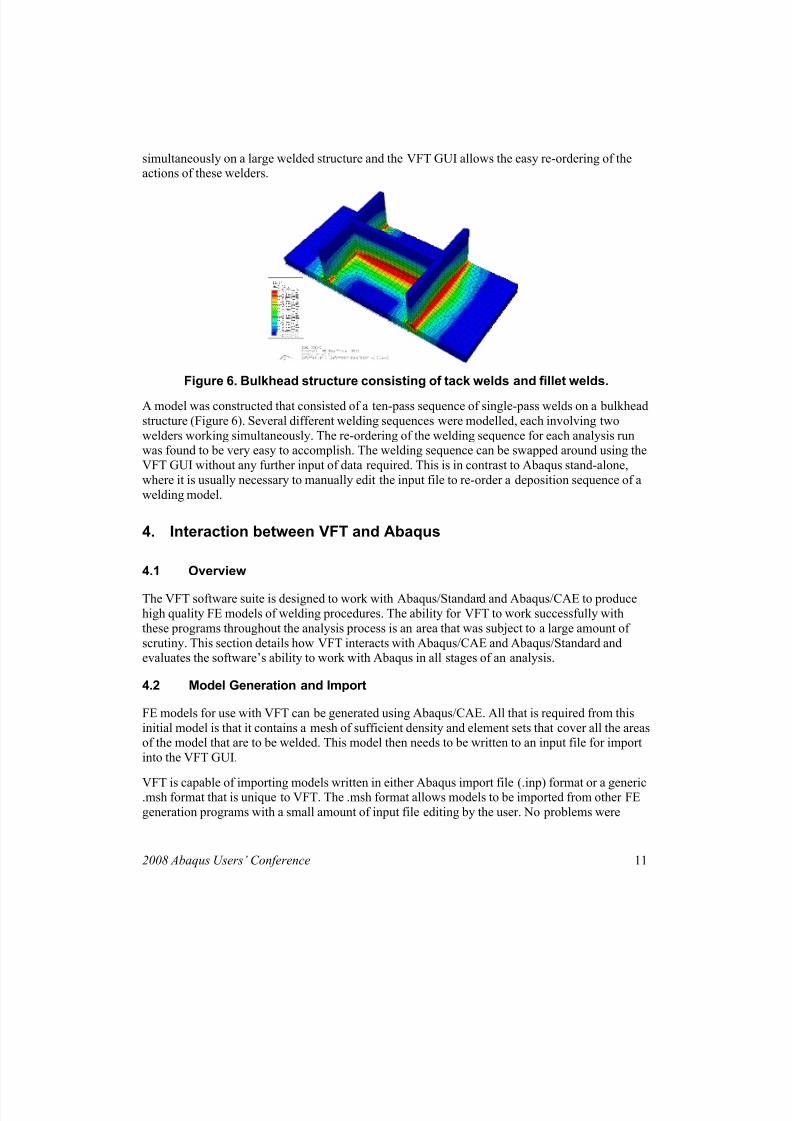
Figure 6. Bulkhead structure consisting of tack welds and fillet welds.
A model was constructed that consisted of a ten-pass sequence of single-pass welds on a bulkhead
structure (Figure 6). Several different welding sequences were modelled, each involving two
welders working simultaneously. The re-ordering of the welding sequence for each analysis runwas found to be very easy to accomplish. The welding sequence can be swapped around using the
VFT GUI without any further input of data required. This is in contrast to Abaqus stand-alone,
where it is usually necessary to manually edit the input file to re-order a deposition sequence of a
welding model.
4. Interaction between VFT and Abaqus
4.1 Overview
The VFT software suite is designed to work with Abaqus/Standard and Abaqus/CAE to produce
high quality FE models of welding procedures. The ability for VFT to work successfully with
these programs throughout the analysis process is an area that was subject to a large amount of
scrutiny. This section details how VFT interacts with Abaqus/CAE and Abaqus/Standard andevaluates the software’s ability to work with Abaqus in all stages of an analysis.
4.2 Model Generation and Import
FE models for use with VFT can be generated using Abaqus/CAE. All that is required from this
initial model is that it contains a mesh of sufficient density and element sets that cover all the areasof the model that are to be welded. This model then needs to be written to an input file for import
into the VFT GUI.
VFT is capable of importing models written in either Abaqus import file (.inp) format or a generic.msh format that is unique to VFT. The .msh format allows models to be imported from other FE
generation programs with a small amount of input file editing by the user. No problems were
2008 Abaqus Users’ Conference 11
8/20/2019 Dawson AUC2008
http://slidepdf.com/reader/full/dawson-auc2008 12/15
encountered in the course of the evaluation with regards to the import of the original model fromAbaqus/CAE to the VFT GUI. The ability to create the initial geometry of the model in
Abaqus/CAE greatly increases the complexity of weld model that can be input into the VFT GUI.
4.3 Structural Analysis
The weld definition process and thermal analysis are carried out by VFT alone. The results from
the thermal analysis are written to a text file in a node/temperature/time format. This format isread by the UMAT-35 subroutine during the final structural analysis, which is carried out using
the Abaqus/Standard solver as a base. The VFT GUI generates all the input files for the structural
analysis automatically and hence no user editing of the files is required. Model specific subroutine
data is also output from the GUI and this is combined with the UMAT-35 template to produce a
model-specific subroutine.
No problems were encountered during the evaluation process relating to the operation of the
UMAT-35 subroutine. It was found to bridge the gap between the VFT GUI and the
Abaqus/Standard solver allowing the user to concentrate on the outputs gained from the analysis,rather than the analysis procedure itself.
4.4 Results Output and Post-Processing
The UMAT-35 subroutine produces a different set of outputs to those usually associated with anAbaqus/Standard run. These outputs are designed to provide as much useful information as
possible on the welding procedure modelled. They also contain data on the annealing and phasetransformation that may be occurring in the material during welding. These modified outputs are
know as solution dependant variables and are summarized in detail in the VFT user manual (Brust,
2006).
The welding specific outputs created by the UMAT-35 routine can be used in a variety of ways toaid post-processing, Thermal outputs such as the maximum temperature reached by each node in
the model are useful if it is necessary to determine the depth of fusion of a weld or the maximumtemperature in a certain area. Outputs that display the volume proportion of each material phase
present in a material allow the user to determine where phase transformation has taken place andwhat the final phase make up of the component is.
5. Evaluation of what VFT adds to Abaqus CAE
5.1 Overview
In the course of the evaluation work carried out using VFT, it has become clear that the softwareexpands significantly on the current limited abilities of Abaqus/CAE and Abaqus/Standard to
model high-temperature fabrication procedures. VFT allows the easy modelling of 3D welding
procedures to be achieved through the use of a GUI. This is something that is not currently
possible using Abaqus stand-alone. This section highlights the improvements made to the Abaqus
package by the VFT software suite and identifies areas where Abaqus/CAE and Abaqus/Standardwould benefit from development.
12 2008 ABAQUS Users’ Conference
8/20/2019 Dawson AUC2008
http://slidepdf.com/reader/full/dawson-auc2008 13/15
5.2 Evaluation of Improvements to Abaqus/CAE
Abaqus/CAE is one of the world leaders in 3D FE modelling and analysis of engineering
components. However, it has been shown to be lacking in its abilities to create and run realistic 3Dmodels of welding procedures. With the current level of interest in residual stress and its analysis,
quick and accurate ways of modelling welding processes are required. Abaqus/CAE does not
currently meet with this requirement.
The VFT software package fills this ‘hole’ in Abaqus/CAE. The GUI that is the centrepiece of thesoftware allows users to deposit welds onto their Abaqus/CAE generated models and run analysis
using 3D moving heat sources. The ability to construct and run such models completely through a
GUI is a significant improvement on the input file editing that is currently required when using
Abaqus stand-alone to perform a similar task.
With the VFT GUI is possible to change the welding parameters, process and bead sequencethrough the use of drop down menus. This allows multiple sensitivity studies to be set up and run
in a short time with relatively little user effort. This is another area where Abaqus/CAE could see
improvement. Once a 3D welding analysis has been set up in Abaqus/CAE it is difficult to alterthe bead sequence or other welding parameters without a large number of adjustments to the
model and its input files. This is not ideal.
5.3 Evaluation of Improvements to Abaqus/Standard
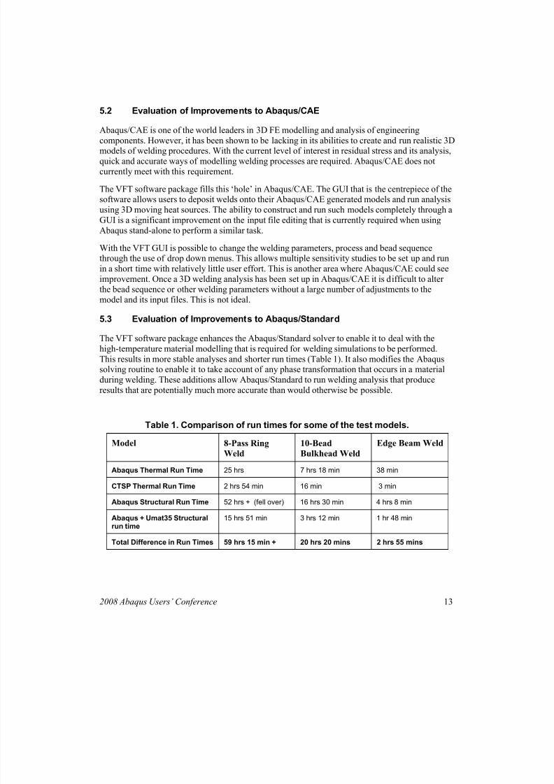
The VFT software package enhances the Abaqus/Standard solver to enable it to deal with the
high-temperature material modelling that is required for welding simulations to be performed.
This results in more stable analyses and shorter run times (Table 1). It also modifies the Abaqussolving routine to enable it to take account of any phase transformation that occurs in a material
during welding. These additions allow Abaqus/Standard to run welding analysis that produce
results that are potentially much more accurate than would otherwise be possible.
Table 1. Comparison of run times for some of the test models.
Model 8-Pass Ring
Weld
10-Bead
Bulkhead Weld
Edge Beam Weld
Abaqus Thermal Run Time 25 hrs 7 hrs 18 min 38 min
CTSP Thermal Run Time 2 hrs 54 min 16 min 3 min
Abaqus Structural Run Time 52 hrs + (fell over) 16 hrs 30 min 4 hrs 8 min
Abaqus + Umat35 Structuralrun time
15 hrs 51 min 3 hrs 12 min 1 hr 48 min
Total Difference in Run Times 59 hrs 15 min + 20 hrs 20 mins 2 hrs 55 mins
2008 Abaqus Users’ Conference 13
8/20/2019 Dawson AUC2008
http://slidepdf.com/reader/full/dawson-auc2008 14/15
The welding-specific solution dependent variables that are output by the UMAT-35 modifiedAbaqus/Standard solver allows a much more in depth analysis of a welding procedure to be
conducted. They also allow the user to easily iterate a welding analysis by displaying outputs such
as the level of fusion or the size of the heat-affected-zone. Abaqus/Standard would benefit fromhaving such outputs included in the stand-alone software.
5.4 Future Potential for Further Integration
This evaluation has highlighted the current gaps in the ability of Abaqus/Standard and Abaqus
CAE to model 3D welding procedures. VFT has been shown to fill most of these gaps by
providing a GUI thorough which welding procedures can be modelled and a subroutine that
significantly improves the high-temperature analysis capability of Abaqus/Standard. Welding
residual stress is an issue that is unlikely to go away in the near future. Both Abaqus/CAE andVFT should develop to keep pace with the increasing interest in this subject.
The further development of both pieces of software to allow even greater integration between the
two can only be beneficial. VFT is a powerful analysis tool but manages (like Abaqus/CAE) tokeep its GUI interface simple and user-friendly. Abaqus/CAE has seen a large amount ofdevelopment in recent years, but modelling of high-temperature fabrication methods is an area that
still needs a lot of development.
The current abilities of VFT provide an excellent model for future developments in Abaqus/CAEthat would meet with the requirements of the residual stress modelling community.
6. Conclusions
The VFT software package is made up of several separate programs. These have been found towork well together and all necessary file generation and output is done automatically. This allows
users with only a general knowledge of FE software to adequately use the VFT programs.
The VFT GUI is a modern, easy to use interface that is capable of operating on either Windows based or Unix based platforms. It allows the user to define welding parameters and material
properties without having to do any manual editing of the input files. This is a significant
improvement on the methods available using Abaqus stand-alone.
The CTSP heat source-modelling tool included in the VFT package is capable of solving weldingthermal models to a high degree of accuracy in a very short period of time. It is capable of
modelling a wide variety of welds with the only real problems being encountered in certain types
of girth weld. It significantly reduces the time required to set up and execute a welding thermalanalysis.
The VFT software is capable of modelling several different material-hardening models. It is alsocapable of modelling the phase change process. Once a user has entered material data it can be
used for any VFT analysis, significantly saving on time and allowing the user to build up a largematerial database. The material modelling used by VFT has been demonstrated to be significantly
more advanced than that employed by Abaqus.
14 2008 ABAQUS Users’ Conference
8/20/2019 Dawson AUC2008
http://slidepdf.com/reader/full/dawson-auc2008 15/15
The UMAT user subroutine supplied with VFT integrates the thermal, material and geometricdata. It allows the material models and CTSP data to be used in an Abaqus environment and has
been shown to require no user editing, whatever the welding case. It models progressive annealing
and material melting / re-melting and outputs a large amount of results data that is not availableusing Abaqus stand-alone.
The VFT software was designed to be used as an add-on for the Abaqus software package and has been shown to interact well with it. Data import and export to the Abaqus platform is smooth and
without error. The ability to export the CTSP thermal output decks into an Abaqus format before astructural run is performed is another useful tool. The solution dependent variables generated by
the UMAT subroutine for viewing in Abaqus allow any welded component to be extensively
analysed.
The VFT software package improves substantially on the abilities of Abaqus to model weldedcomponents. The material and thermal modelling used by VFT is significantly more advanced
than that contained in Abaqus. VFT is capable of modelling welded components that would not be
possible using the Abaqus software alone. VFT significantly reduces the time required to performany type of welding analysis. Its interface system ensures that users no longer have to be FE
experts to model complex 3D welding processes.
The further integration of VFT and Abaqus/CAE would result in a program capable of modelling
the vast majority of welding procedures in a quick, accurate and user-friendly manner. The currentabilities of VFT provide an excellent model for future developments in Abaqus/CAE that would
meet with the requirements of the residual stress modelling community.
7. References
1. Brust, F. W., “VFT: Virtual Fabrication and Weld Modelling Software, Version 2.00,” User
Manual, Battelle Memorial Institute, Columbus, Ohio, 2006.
2. Brust, F. W., “CTSP-SOLID: A Comprehensive Thermal Solution Procedure for Solid FEMModels,” User Manual, Battelle Memorial Institute, Columbus, Ohio, 2006.
3. Brust, F. W., “UMAT-WELD Version 3.5: A Welding Specific User Material RoutineInterfaced with Abaqus”, User Manual, Battelle Memorial Institute, Columbus, Ohio, 2005.
4. Bagshaw, N., and J. Mawella, “Prediction and Control of Distortion During Welding in Ship
Panels”, TWI, UK, 2007
5. Yang, Y. P., Brust, F. W., and Z. Cao, “Virtual Fabrication Technology Weld Modelling Tool
and its Applications in Distortion Predictions”, ASME PVP Conference Paper, July 2003.
6. Dong, P., Brust, F. W., and J. Zhang, “A Constitutive Model for Welding Process SimulationUsing Finite Element Methods”, Battelle Memorial Institute, Columbus, Ohio, 1997.
2008 Abaqus Users’ Conference 15